1
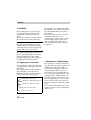
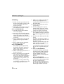
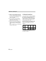
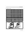
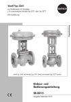
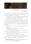
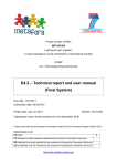
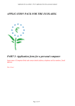
Angle Seat Valve
Type 3353
Fig. 1 ⋅ Type 3353
Mounting and
operating instructions
EB 8139 EN
Edition August 2002
Contents
Contents
1.
2.
2.1
3.
3.1
3.2
4.
5.
6.
Safety instructions
Design and principle of operation
Installation . . . . . . . . . . .
Signal pressure connection . . . .
Maintenance – Replacing parts .
Plug seal . . . . . . . . . . . . .
Packing . . . . . . . . . . . . .
Altering the spring force . . . . .
Dimensions in mm . . . . . . . .
Customer inquiries . . . . . . . .
.
.
.
.
.
.
.
.
.
.
.
.
.
.
.
.
.
.
.
.
.
.
.
.
.
.
.
.
.
.
.
.
.
.
.
.
.
.
.
.
.
.
.
.
.
.
.
.
.
.
.
.
.
.
.
.
.
.
.
.
.
.
.
.
.
.
.
.
.
.
.
.
.
.
.
.
.
.
.
.
.
.
.
.
.
.
.
.
.
.
.
.
.
.
.
.
.
.
.
.
.
.
.
.
.
.
.
.
.
.
.
.
.
.
.
.
.
.
.
.
.
.
.
.
.
.
.
.
.
.
.
.
.
.
.
.
.
.
.
.
.
.
.
.
.
.
.
.
.
.
.
.
.
.
.
.
.
.
.
.
.
.
.
.
.
.
.
.
.
.
.
.
.
.
.
.
.
.
.
.
.
.
.
.
.
.
.
.
.
Page
. 3
. 4
. 4
. 4
. 5
. 6
. 8
. 9
. 10
General safety instructions
The control valve may only be assembled, started up or serviced by experi
2
EB 8139 EN
enced personnel familiar with the product. Employees or third persons must
not be exposed to any danger.
The control valve fulfills the requirements of the European Pressure Equipment
Directive 97/23/EC. Valves with a CE marking have a declaration of conformity that includes information on the applied conformity assessment procedure. The declaration can be found in the appendix of these instructions.
For appropriate operation, make sure that the control valve is only used in
areas where the operating pressure and temperatures do not exceed the operating values based on the valve sizing data submitted in the order. The manufacturer rejects any responsibility for damage caused by external forces or
any other external influence!
Any hazards which could be caused in the control valve by the process medium, operating pressure or signal pressure are to be prevented by means of
the appropriate measures.
Proper shipping and appropriate storage are assumed.
Caution! For installation and maintenance work on the valve, make sure the
relevant section of the pipeline is relieved of pressure and, depending on the
process medium used, drained as well. If necessary, allow the control valve to
cool down or warm up to reach ambient temperature prior to starting any
work on the valve.
When working on the valve, make sure that the pneumatic air supply as well
as the control signal are disconnected to prevent any hazards due to moving
parts.
Design and principle of operation
1. Design and principle of operation
The pneumatic control valve consists of a
angle seat valve that has a plug with soft
sealing and a pneumatic piston actuator.
Depending on the version, the actuator can
be equipped with a mechanical manual
override or an electric limit switch.
The control valve is designed for on/off control in process engineering and plants with
industrial requirements. It is suitable for
liquids, vapors and gases at temperatures
from –10 to 180 °C and a nominal pressure of PN 40.
The process medium flows through the valve
in the direction indicated by the arrow. The
signal pressure applied to the piston actuator determines the position of the plug and
thus the cross-sectional area of flow between the seat and plug.
1
2
9
13.1
8
13
14
4.1
4.4
The actuator stem (2) is sealed at the valve
end by a self-adjusting packing consisting
of PTFE V-rings (4.4) and at the actuator
end by a shaft sealing ring (4.1).
Fail-safe position:
The fail-safe position of the control valve
when the air supply fails is determined by
how the piston and spring are arranged in
the actuator.
Valve CLOSED (actuator stem extends)
The actuator spring closes the valve upon
air supply failure. The valve opens as the
signal pressure increases.
Valve OPEN (actuator stem retracts)
The actuator spring opens the valve upon
air supply failure. The valve closes as the
signal pressure increases.
Body
Plug with
plug/actuator stem
4.1 Shaft sealing ring
4.4 Packing rings
8 Piston
9 Spring(s)
13 Venting plug
13.1Filter
14 Signal pressure
connection
Valve normally closed
FA/NC/TS
Valve normally open
FE/NO/TR
9
8
14
13
13.1
4.1
4.4
2
1
2
1
Fig. 2 ⋅ Sectional view of the valve
EB 8139 EN
3
Installation
2. Installation
Any mounting position is possible, but we
recommend mounting the valve in a horizontal pipeline with actuator facing upwards.
The direction of flow must coincide with the
direction of the arrow on the valve body.
NOTE!
The valve must be installed in a location
with the least amount of vibration possible
and without stress. If necessary, support the
pipeline near to the end connections.
The signal pressure connection also allows
the attachment of an adapter plate that complys with VDI/VDE 3845 for mounting a
solenoid valve.
The actuator can be turned as required to
connect the signal pressure line.
Customary pipe couplings can be used for
metal and copper pipes or plastic tubes.
Prior to connecting the supply air lines,
blow through them to make sure they are
not blocked.
Since sealing parts, globules and other impurities carried along by the medium may
impair the tight shut-off of the seat and
plug, flush out the pipeline thoroughly prior
to installing the valve in the pipeline.
2.1 Signal pressure connection
The signal pressure connection and venting
are designed as boreholes with a G1/4 female thread.
The venting borehole must be fitted with a
replaceable filter (13.1) with order no.
0550-0213. This filter can be removed by
first unscrewing the venting plug (13).
For fail-safe position: Valve OPEN
FE/NO/TR AUF/Open/Ouvert
FA/NC/TS
ZU/Close/Ferme
For fail-safe position: Valve CLOSED
Fig. 3 ⋅ Signal pressure connection
4
EB 8139 EN
3. Maintenance – Replacing parts
The control valve is subject to normal wear
especially at the seat, plug and packing. Depending on the application conditions,
check the valve at regular intervals to prevent possible failure before it can occur.
If the valve does not close tightly, this may
be caused by dirt lodged between the seat
and plug or due to a damaged plug seal.
If the valve leaks, this may be due to a defective body gasket (3.1), or if the medium
leaks out of the borehole (3.2) at the side,
there may possibly be a leak in the packing
(4.4).
We recommend removing the parts, cleaning them, and, if necessary, replacing them
with new ones.
Maintenance – Replacing parts
NOTE!
Remove the valve from the pipeline
to perform any assembly work.
First relieve pressure from the part of
the plant to be worked on and drain
it.
If applicable, let the part of the plant
to be worked on first cool down before starting!
Clean the valve body, paying particular
attention to the seat bore.
2. Unscrew the countersunk screw (2.1)
using a 3 mm hex screwdriver, while
holding the plug/actuator stem at the
flattened part stationary with a 8 mm
open-end wrench.
3. Remove the PTFE seal (2.2) and plug
disk (2.3).
3.1 Plug seal
4. Thoroughly clean all the parts and replace the PTFE seal with a new one.
1. Position a 26 mm open-end wrench on
the valve bonnet and unscrew the entire
actuator including the valve bonnet
from the valve body.
5. Assemble in the reverse order, replacing the body gasket (3.1) at the valve
bonnet with a new one.
The tightening torques required for the
valve bonnet are listed in the table, Fig. 4.
DN
3
3.1
Tightening
torque
G 1/2...G 3/4"
15...20
40 Nm
G 1...G 1 1/4"
25...32
80 Nm
2
2.1
2.2
2.3
1
2
2.1
2.2
2.3
3
3.1
Body
Plug with plug/actuator
stem
Countersunk screw
PTFE seal
Plug disk
Valve bonnet
Body gasket
Fig. 4 ⋅ Replacing the plug seal
EB 8139 EN
5
Maintenance – Replacing parts
3.2 Packing
1. Position a 26 mm open-end wrench at
the valve bonnet and unscrew the entire
actuator including the valve bonnet
from the valve body.
2. Unthread the screws (6) in an even pattern and lift off the actuator cover (7).
Valve normally CLOSED (FA)
3. Lift off the spring(s) (9) first and then
remove the cap (10).
4. Unscrew the nut (11) from the actuator
stem using a socket wrench, while holding the plug/actuator stem at the flattened part stationary with a 8 mm openend wrench.
5. Remove the flat washer (12), piston (8)
including the lip ring (8.1) and disk
(9.1).
6. Remove the O-ring (8.2) and washer
(8.3) from the actuator stem.
Valve normally OPEN (FE)
Disassemble as previously described,
but lift off the flat washer and O-ring
with the piston and then remove the
disk (9.1) and spring (9).
7. Pull the actuator/plug stem down out of
the valve bonnet (3).
8. Remove the retaining screw (4.2) at the
side using a 2 mm hex screwdriver,
then unscrew the guided bushing (4) including the actuator base (5) from the
valve bonnet (3) using a 24 mm openend wrench.
If necessary, press the guided bushing
out of the base and replace the top and
bottom disk(s) (5.2) with new ones.
6
EB 8139 EN
9. Pull the entire packing out of the valve
bonnet using an appropriate tool.
Carefully clean all the parts and renew
the packing (4.4).
10. Insert the actuator/plug stem into the
valve bonnet (3).
11. Slide the packing parts in sequence
starting with the spring (4.5), washer
(4.3) and packing rings (4.4) over the
actuator stem into the valve bonnet.
12. Place the top disk (5.2) in the actuator
base. Attach the O-ring (5.3) and insert
the guided bushing (4) into the actuator
base.
13. Place the bottom disk (5.2) on the valve
bonnet.
Thread the guided bushing with the actuator base over the actuator stem onto
the valve bonnet (3).
Tighten the guided bushing only to the
point where the actuator base (5) can
still be twisted over the disks.
Screw tight the retaining screw (4.2) at
the side to fix the guided bushing into
place.
14. Valve normally CLOSED (FA)
First slide the washer (8.3) and the Oring (8.2) onto the actuator stem, then
put on the piston (8) including the lip
ring (8.1) and flat washer (12).
Insert the disk (9.1) and spring (9) into
the piston.
Valve normally OPEN (FE)
First place the washer (8.3) on the actuator stem, then put the spring (9) with disk
(9.1) on the actuator base (5).
Slide the piston (8) including the lip ring
(8.1) over the actuator stem, then put on
the O-ring (8.2) and flat washer (12).
Maintenance – Replacing parts
Valve normally OPEN
FE/NO/TR
Valve normally CLOSED
FA/NC/TS
10
9
11
9.1
9
8
8.1
8.2
8.3
7
6
4
4.1
4.2
4.4
4.3
4.5
8
12
13.1
13
1
2
14
5.1
9.1
5
5.2
5.3
5.2
3.2
3
3.1
2
1
Body
Plug
with plug/actuator
stem
3
Valve bonnet
3.1 Body gasket
3.2 Borehole
4
Guided bushing
4.1 Shaft sealing ring
4.2 Retaining screw
4.3 Washer
4.4 Packing rings
4.5 Spring
5
Actuator base
5.1 O-ring
5.2 Disk
5.3 O-ring
6
Screws
7
Actuator cover
8
Piston
8.1 Lip ring
8.2 O-ring
8.3 Washer
9
Spring(s)
9.1 Disk
10
Cap
11
Nut
12
Flat washer
13
Venting plug
13.1 Filter
14
Signal pressure
connection
Fig. 5 ⋅ Replacing the packing
EB 8139 EN
7
Maintenance – Replacing parts
15. Tighten nut (11) intended for fastening
the piston, while holding the plug/actuator stem at the flattened part stationary
with a 8 mm open-end wrench.
Screw on cap (10).
16. Put on actuator cover (7) and fasten
tight onto the actuator base by screwing evenly on the screws (6).
17. Place the valve bonnet including the actuator onto the valve body and screw
tight. If necessary, renew body gasket
(3.1).
Refer to the table in Fig. 4 for tightening
torque for valve bonnet.
4. Altering the spring force
Control valves that are normally CLOSED in
the fail-safe position (FA/NC/TS) and have
the nominal sizes DN 40 and 50 (1 1/2
and 2") with 90 cm2 actuator can be fitted
with one or two actuator springs (marked
on the nameplate with I or II).
By adding a spring or removing the inside
spring, the permissible differential pressure
and associated signal pressure can be
changed.
Actuator
cm2
Version
90
FA/NC/TS
Spring
force
Quantity
Signal
pressure
bar
1140 N
1
3.8
2160 N
2
5.4
For assembly or disassembly, proceed as
described in chapter 3.
8
EB 8139 EN
Dimensions in mm
5. Dimensions in mm
15 (1⁄2”)
Nominal size
DN
Installation length L
mm
65
End-to-end length L1
mm
170
20 (3⁄4”)
25 (1”)
32 (11⁄4”)
40 (11⁄2”)
50 (2”)
75
90
110
120
150
175
197
205
210
226
Height inc. actuator H
mm
193
194
211
212
224
226
Body connection
G
G 1⁄2
G 3⁄4
G1
G 11⁄4
G 11⁄2
G2
Thread length t
mm
15
16
19
22
22
26
Valve weight
kg
0.28
0.33
0.64
0.8
1.3
1.9
Nominal size
DN
15 (1⁄2”)
20 (3⁄4”)
25 (1”)
32 (11⁄4”)
40 (11⁄2”)
50 (2”)
Installation length L
mm
100
120
150
160
180
190
End-to-end length L1
mm
187
197
227
218
230
241
Version with welding ends
Height inc. actuator H
mm
197
199
214
223
230
229
∅ d1 connection
mm
18.1
23.7
29.7
38.4
44.3
55.1
Wall thickness S
mm
Valve weight
kg
1.6
0.28
2
0.33
0.64
2.6
0.8
1.3
1.9
Pneumatic piston actuator
30 cm2 / ∅ 63
Effective area/∅
Body diameter ∅D
mm
60 cm2 / ∅ 90 (1 spring)
100
127
G 1⁄4
Signal pressure connection
Weight
60 cm2 / ∅ 90 (2 springs)
kg
1.35
2.2
Version with
female thread
2.75
Version with
welding ends
H
ØD
H
L
t
L1
ISO 4200
S
ØG-ISO228/1
ØD
Ød1
Version
L
L1
EB 8139 EN
9
Customer inquiries
6. Customer inquiries
Should you have any inquiries, please submit the following details:
Order number
Type, product number, nominal size and
version of the valve
Pressure and temperature of the process
medium
Flow rate in m3/h
Signal pressure of the actuator
Installation drawing
10
EB 8139 EN
Declaration of Conformity
Number 73
For the following pressure equipment
Bevel-Valves Product number 3353
DIN-Version
With Steel-Body
We declare conformity with the demands of the
Pressure Equipment Directive
97 / 23 / EG
Applied Conformity Assessment Procedure
For fluids acc. to art.3 para.1 1.3.b and 1.3.a second line
of May 1997
Module A
The Manufacturer’s Quality Assurance System is monitored by following Notified Body:
Bureau Veritas S. A.
The Design is based on the methods of
and
prEN 12 516-2
DIN 3840
Manufacturer:
SAMSON AG
Weismüllerstr. 3
60 314 Frankfurt
Frankfurt, 19.7.2002
________________________
________________________
Lingnau
Head of Technical Sales Department
Nebel
Head of Control Valves Department
C hairman of the
Supervisory Board:
Dr. Nik olaus Hensel
Executive Board: G ernot Frank (C EO)
Prof. Dr. Heinfried Hoffmann,
Dr. Edgar Linde rmann, Alfred Mach
Registration Office
Frankfurt am M ain
No. HR B 7131
Created
24.10.01 Cp
4
34719
08.8.02 Cp Wt
Checked
19.11.01 Kb
07.03.02 Wt
3
34517
05.6.02 Cp Wt
State
No.
Standard
Modification
Weismüllerstraße 3 · D- 60314 F rankfurt/M.
PO Box 10 19 01 · D- 60019 F rankfurt/M.
Internet: http://www.samson.de
1010–3973
Declaration of Conformity
4
Mod..
Phone +49 69 40 09 0
Fax +49 69 40 09 15 0
7
73
Page
No.
EB 8139 EN
11
EB 8139 EN
S/Z 2002-09
SAMSON AG ⋅ MESS- UND REGELTECHNIK
Weismüllerstraße 3 ⋅ 60314 Frankfurt am Main ⋅ Germany
Phone: +49 69 4009-0 ⋅ Fax: +49 69 4009-1507
Internet: http://www.samson.de