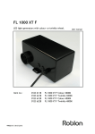
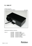
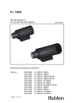
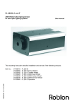
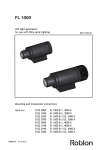
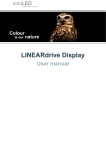
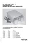
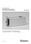
1
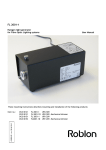
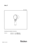
FL 1000 XT C DMX
LED light generators with DMX controlled colour- or twinkle wheel.
Dual light generators with both color and twinkle.
All units with DMX controlled dimming 0-100%.
User manual
Item no.:
+99082098 02.11.2015
0123 6310
0123 6315
0123 6320
0123 6325
0123 6410
0123 6420
FL 1000 XT C DMX Colour 3000K
FL 1000 XT C DMX Twinkle 3000K
FL 1000 XT C DMX Colour 4000K
FL 1000 XT C DMX Twinkle 4000K
FL 1000 XT C DMX Dual 3000K
FL 1000 XT C DMX Dual 4000K
Contents.
1 Introduction
2 Product overview when unpacking
3 DMX addressing the light generator
3.1 Factory default setting
3.2 Factory custom set up addresses
3.3 Setup of the DMX adresses on site
4 DMX protocol
5 Surface-mounting
6 Installation
7 Installing in closed compartments
8 Installing one or more light generators
9 Technical data
10 Spare parts
11 Accessories
12 Troubleshooting
1. Introduction.
Roblon FL 1000 XT C DMX light generator with DMX controlled colour and
twinkle wheel as well as very smooth controlled dimming are designed for
use outdoors with glass or PMMA fibre in all installation set-ups, including in
closed compartments.
Weatherproof, waterproof LED light generator.
Cuts energy consumption by min. 63% compared with equivalent halogen
generators. For functional and decorative tasks outdoors and in wet
locations. Ideal for fountains, public art, facades, signage, parks, gardens
and swimming pools
Follow the installation instructions correctly in order to ensure
safe operation
enhanced functionality
extended lifetime for components
uninterrupted illumination
2
2. Product overview
when unpacking the light generator.
FL 1000 XT C DMX light generator
Allen key
Screws w/ plugs
User manual
Light port
OUT DMX
IN DMX signal
and programming
Connect wire to mains
3
3. Addressing set up of the light generator:
3.1. Factory default setting:
Factory default Address settings are as follows:
Electronically setting:
CH1 dimming 0-100%
CH2 Dimming 16 bit (High resolution 65536 levels).
Mecannically setup directly on the hardware inside the unit:
CH3 DMX addressable special functions.
CH4 Colour wheel.
CH5 Twinkle wheel.
3.2. Factory custom set up addresses:
You can order a custom addressing (part number 9903 0071) of the unit when
ordering the light generators. The light generators will be supplied with a
label informing about the settings.
3.3. Setup of the DMX addresses on site:
3.3.1. Please note that the following steps requires a skilled technician.
And that working on a light generator with the lid off requires a trained
electrican. Use caution!
Turn the light generator upside down
and remove the eight screws and
then remove the lid and sealing.
On www.eldoled.com/software download software for
eldoLED TOOLbox pro:
eldoLED FluxTool software v1.04 MAC.zip
eldoLED FluxTool software v1.04 WIN.zip or
eldoLED Showmaster DMX software v 1.5.zip
Download and follow user manuals in: User manuals/Accessories/User Manual
TOOLbox PC Software v1.0.pdf.
Connect TOOLbox as shown and follow eldoLED manual.
120 - 240V
eldoLED TOOLbox pro
0160 0336
4
Programming cable
0160 0337
DMX in
According to DMX protocol driver address should be set to light generator
desired DMX address.
Driver:
Channel 1: Dimming 0-100% light
Channel 2: Dimming. Fine resolution, 16 bit (LSB: Least Significant Bit).
(One DMX channel represents a number from 0 to 255 which is a 8 bits number.
In order to have more than 256 DMX steps, two channels can be combined (256
times 256). This is called 16 bits resolution).
3.3.2. Wheel control board code on driver. Wheel must be set to driver DMX
address +2.
Example: DMX address 1 on driver - wheel sets to address 3
DMX address 8 on driver - wheel sets to address 10.
x1
x10
Light
Wheel
generator Driver control
channel
board
CH 1
1
3
CH 2
2
4
CH 3
3
5
CH 508
508
510
x100
3.3.3. When the light generator is addressed replace the sealing and the lid
and fasten the screws on cross to example as shown to up.
Beware of the sealing: it has to lay plain on the light generator but may not
be destroyed.
It is critical to be IP 65.
5
3
7
2
6
1
8
4
5
Connecting the light generators.
FL 1000 XT C DMX
# 1 Address X
FL 1000 XT C DMX
# 2 Address X + 4
Controller
Address (First used channel in light generator)
DMX OUT
DMX IN
4. DMX protocol.
CH 1
0 - 255
CH 2
0 - 255
Control:
CH 3
000 - 050
051 - 070
071 - 080
081 - 100
101 - 120
121 - 144
145 - 160
161 - 179
180 - 255
6
0 - 100% light intensity
Hi - res 16 bit dimming (LSB)
5 sec. delay on all functions
Not assigned
Shortest mode
Not assigned
Linear mode
Not assigned
Reset wheel
Not assigned
Reset wheel
Not assigned
CH 4
000 - 200
000 / 200
033
067
100
133
167
Colour wheel:
Position of wheel
White
Green
Orange
Blue
Red
Yellow
201 206 208 211 213 216 220
221 224 226 229 231 233 236 238 241 245
246 249 251 254 -
Not assigned
Variable speed of rotation clockwise (10 rpm.)
Variable speed of rotation clockwise (5 rpm.)
Variable speed of rotation clockwise (3 rpm.)
Variable speed of rotation clockwise (2 rpm.)
Variable speed of rotation clockwise (1 rpm.)
Variable speed of rotation clockwise (0.8 rpm.)
Variable speed of rotation clockwise (0.6 rpm.)
Variable speed of rotation clockwise (0.4 rpm.)
Variable speed of rotation clockwise (0.2 rpm.)
Variable speed of rotation clockwise (0.1 rpm.)
Variable speed of rotation counter clockwise (10 rpm.)
Variable speed of rotation counter clockwise (5 rpm.)
Variable speed of rotation counter clockwise (3 rpm.)
Variable speed of rotation counter clockwise (2 rpm.)
Variable speed of rotation counter clockwise (1 rpm.)
Variable speed of rotation counter clockwise (0.8 rpm.)
Variable speed of rotation counter clockwise (0.6 rpm.)
Variable speed of rotation counter clockwise (0.4 rpm.)
Variable speed of rotation counter clockwise (0.2 rpm.)
Variable speed of rotation counter clockwise (0.1 rpm. )
205
207
210
212
215
219
223
225
228
230
232
235
237
240
244
248
250
253
255
7
CH 5
000 - 200
000 / 167
033 - 133
201 - 205
206 - 207
208 - 210
211 - 212
213 - 215
216 - 219
220
221 - 223
224 - 225
226 - 228
229 - 230
231 - 232
233 - 235
236 - 237
238 - 240
241 - 244
245
246 - 248
249 - 250
251 - 253
254 - 255
8
Twinkle wheel:
Position of wheel
White / open
Only twinkle
Not assigned
Variable speed of rotation
Variable speed of rotation
Variable speed of rotation
Variable speed of rotation
Variable speed of rotation
Variable speed of rotation
Variable speed of rotation
Variable speed of rotation
Variable speed of rotation
Variable speed of rotation
Variable speed of rotation
Variable speed of rotation
Variable speed of rotation
Variable speed of rotation
Variable speed of rotation
Variable speed of rotation
Variable speed of rotation
Variable speed of rotation
Variable speed of rotation
Variable speed of rotation
clockwise (10 rpm.)
clockwise (5 rpm.)
clockwise (3 rpm.)
clockwise (2 rpm.)
clockwise (1 rpm.)
clockwise (0.8 rpm.)
clockwise (0.6 rpm.)
clockwise (0.4 rpm.)
clockwise (0.2 rpm.)
clockwise (0.1 rpm.)
counter clockwise (10 rpm.)
counter clockwise (5 rpm.)
counter clockwise (3 rpm.)
counter clockwise (2 rpm.)
counter clockwise (1 rpm.)
counter clockwise (0.8 rpm.)
counter clockwise (0.6 rpm.)
counter clockwise (0.4 rpm.)
counter clockwise (0.2 rpm.)
counter clockwise (0.1 rpm. )
5. Surface-mounting.
5a Surface-mounting.
1. Attach to surface using two screws in the baseplate holes.
2. Vertical installation: to maintain IP 65 protection, mount with the light port
facing down.
170 mm
between
Ø6 mm
holes
5b Bracket-mounting.
1. Attach the bracket (not supplied; see Accessories) to the surface using two
screws.
2. Mount the light generator on the bracket.
140 mm
between
Ø6 mm
holes
9
6. Installation.
1. Remove the plastic plug on the baseplate, directly bellow the light port.
2. Insert the common end fully in the light port.
3. Tighten the screw on the base with the Allen key.
4. Insert the plastic plug. (Important to be IP 65!)
5. Ensure all installation and ventilation requirements are met.
6. Connect the power cord to the mains.
10
7. Installing in closed compartments.
Requirements:
Enough space to allow natural heat transmission through surfaces
Surfaces should not be insulated
Air volume per light generator minimum 0.05 m³
Ventilation holes per light generator with min. 20 cm² air inlet and min. 20
cm² air outlet
Inlet and outlet ventilation holes opposite each other
Max. ambient temperature 45ºC. (Measuring temperature: see
‘Troubleshooting’)
(0.3 m)
0.05 m³
(0.3 m)
(0.6 m)
8. Installing one or more light generators.
Requirement: min. 100 mm distance between adjacent light generators in
order to ensure sufficient heat transmission
100 mm
500 mm
11
9. Technical data.
Light port
Fibre type
Total power consumption @ 700 mA
Supply voltage
Applied LED
Light source lifetime
CCT (nominal)
CRI8 (Ra) typical value
Protection rating
Driver type
Driver lifetime
Dimmable
Thermal protection
Cooling system
Noise level
Ambient temperature
Material
Dimensions (L x H x W)
Weight
Safety
DMX Connection
12
Ø28 mm
PMMA / Glass
26 W (Single wheel)
31 W (Dual wheel)
120-240 V / 50-60 Hz
LUXEON S1000 LXS8-PW30 (3,000 K)
LUXEON S1000 LXS8-PW40 (4,000 K)
50,000 hours
3,000 K / 4,000 K
85
IP 65
Electronic
50,000 hours
DMX
Integrated auto
Natural convection
N/a
-20°C to 45°C
EN AW-5754 (AlMg 3) + POM
298 x 185 x 151
3.8 kg
CE, RoHS, F
XLR 5 pin
10. Spare parts.
Image
Model designation
Description
Item no.
Eldoled
Driver Powerdrive Eldoled 50W
1104 1300
Colour wheel
Standard 6 colour
5100 0085
Twinkle wheel
5100 0092
Diode LED
LED module, no cooling
0129 4004
Effekt motor for DMX
Stepper motor 1.8°
6400 4000
Spring-clip 4 mm
Lock for wheel
9100 6304
14
11. Accessories.
Image
Model designation
Description
Item no.
Mounting bracket
Bracket that can be padlocked
0126 7000
Colour wheel mix.
Standard 6 colour
Custom specified colour wheel
5100 0153
Colour wheel special
Rosco Permacolour
Custom specified colour wheel
5100 0154
EldoLED TOOLbox pro
0160 0336
Programming cable for
EldoLED toolbox pro
RJ45 to XLR 5 pin
0160 0337
DMX adressing
9903 0070
Addressing of light generator
form factory
0160 0302
Sunlight USB Controller
14
DMX programming
Programming of Controller
9903 0071
DMX Cable
Cable between control unit and
9903 0057
Light generator
Please state required length
Spring-clip 4 mm
Lock for wheel
9100 6304
Kit for twinkle wheel
For insert in twinkle wheel to
avoid constant white light.
0126 6220
12. Troubleshooting.
Problem
Trace the problem
Solution
No light
Is the power on?
Is the power cord connected properly?
Is the light generator too hot*?
Is the LED working?
Turn the power on
Connect the power cord properly
Check it is installed according to the
instructions.
Switch generator off.
Let it cool for 15 minutes.
Try again.
Replace the LED
Is the Supply fuse intact?
Replace the Supply fuse
Check DMX
Set correct address, value and level
Has the light been dimmed via DMX
Increase brightness using DMX
Controller
Clean filter with damp cloth
Dry with lint-free cloth
Light output has
diminished
Is the harness common end dirty?
* Ambient temperature: max. 45°C. Measured 50 mm from light generator.
Surface temperature: max. 73°C. Measured 15 mm from edge on top of light generator when it has been running for min. 1 hour
15
Roblon accepts no responsibility for possible errors in printed and electronic material. Roblon reserves the right to alter or discontinue
products without notice. ©2012, Roblon A/S
Roblon Lighting
Nordhavnsvej 1
9900 Frederikshavn
Denmark
Tel: +45 9620 3366
Fax: +45 9620 3396
[email protected]
www.roblon.com