1
LINEARdrive Display
User manual
LINEARdrive Display
User manual
Disclaimer
All information and content available on or accessible through the eldoLED website, all information contained in any eldoLED documentation, whether provided electronically or in hardcopy, such as product
manuals, and all information and content in e-mails or other ways of communication used by eldoLED,
(collectively hereafter referred to as: ‘the Information’) has been prepared solely fro the purpose of providing information about eldoLED products and teh eldoLED companies (“eldoLED”as used herein, refers to eldoLED B.V. and any of its affiliated companies.) While the content hereof has been prepared by
eldoLED with the utmost care, some information may nevertheless be incomplete, incorrect or may become outdated in time. TO THE FULLEST EXTENT PERMISSIBLE BY LAW, ELDOLED MAKES NO
REPRESENTATIONS OR WARRANTIES OF ANY KIND, WHETHER EXPRESS OR IMPLIED, FOR
THE CURRENCY, ACCURACY, OR COMPLETENESS OF ANY INFORMATION, AS DEFINED
ABOVE. FURTHERMORE, ELDOLED MAKES NO REPRESENTATIONS OR WARRANTIES IN CONNECTION TO ITS PRODUCTS, INCLUDING WARRANTIES ABOUT ITS PRODUCTS’ MERCHANTABILITY OR FITNESS FOR A PARTICULAR PURPPOSE, UNLESS EXPLICITLY MADE AND
PROVIDED BY ELDOLED IN WRITING TO THE PURCHASER OF ITS PRODUCTS. The provided Information must not be relied upon in connection with any investment decision.
eldoLED B.V. cannor be held liable for any direct or indirect loss or damage resulting from the use of the
Information and/or resulting from the use of its products or material(s), except in the event of actions
verging on eldoLED’s gross intent or intentional recklessness. ELDOLED’S MAXIMUM AGGREGATE
LIABILITY FOR ANY CAUSES WHATSOEVER, AND REGARDLESS OF THE FORM OF ACTION,
WILL AT TIMES BE LIMITED TO 100,- EURO OR THE PURCHASE AMOUNTS PAID TO ELDOLED,
IF ANY, IN CONNECTION TO THE PRODUCTS ON WHICH THE LIABILITY CLAIM IS BASED.
All intellectual property rights relating to the Information and all eldoLED products, belong to and remain
with eldoLED B.V. and/or its licensor(s) at all times. The Information and the eldoLED products may not
be used in any way without eldoLED B.V.’s and/or its licensor’s prior explicit written consent.
eldoLED develops and produces building blocks for control of LED lighting. Continuous technological innovation beiong one of the pillars of eldoLED’s company philosophy, eldoLED has developed and continues to develop breakthrough solutions in the filed of solid-state lighting. eldoLED’s steadily growing IP
portfolio proves eldoLED’s commitment to help its customers to bring SSL applications to a higher level.
Because of eldoLED’s leading position in the field and its sophisticated knowledge of the market, it is
very unlikely that its products infringe upon intellectual property rights of third parties. However, due to
the nature of intellectual property protection (e.g the secretive nature of patent applications), eldoLED,
like any other company, cannot give any warranties in this respect. Furthermore, eldoLED cannot vouch
for any system built by a third party in which eldoLED’s building blocks are comprised.
The laws of the Netherlands govern this website and (the use of) the Information, the sale and use of
any of the eldoLED products, and all business relationships between eldoLED and third parties. Disputes
will be submitted exclusively to the applicable judge of the court in ‘s-Hertogenbosch, the Netherlands.
ANY CAUSE OF ACTION ARISING OUT OF OR RELATED TO THIS WEBSITE, (THE USE OF) THE
INFORMATION, OR ANY OF THE ELDOLED PRODUCTS, MUST COMMENCE WITHIN ONE (1)
YEAR AFTER THE CAUSE OF ACTION ACCRUES. OTHERWISE, SUCH CAUSE OF ACTION IS
PERMANENTLY BARRED.
©
4
All rights reserved eldoLED 2007-2009
Table of contents
1 Product description ............................................................................................................ 9
1.1 Setup is a breeze! ..................................................................................................... 9
1.2 Robust thermal management.................................................................................... 9
1.3 ShowMaster ............................................................................................................ 10
1.4 Low EMI .................................................................................................................. 10
1.5 Easy to connect ...................................................................................................... 11
2 Mounting the driver/controller ......................................................................................... 13
2.1 Realizing the right thermal conditions ..................................................................... 13
2.2 Removing the cover ................................................................................................ 13
2.3 Preparing the mounting surface .............................................................................. 14
2.4 Fastening the driver/controller to the surface.......................................................... 14
3 Connecting the driver/controller...................................................................................... 17
3.1 Required wire sizes................................................................................................. 17
3.1.1 LINEARdrive 180 ........................................................................................ 17
3.1.2 LINEARdrive 720 ........................................................................................ 18
3.2 Removing the strain reliefs ..................................................................................... 18
3.3 Connecting the leads .............................................................................................. 20
3.3.1 Locating the right connector ....................................................................... 21
3.3.1.1 Connecting power leads ................................................................. 21
3.3.1.2 Connecting an external input device .............................................. 22
3.3.1.3 Connecting DMX network cabling .................................................. 22
3.3.1.4 Connecting DALI network cabling .................................................. 22
3.3.1.5 Connecting LED groups ................................................................. 23
3.4 Replacing the strain reliefs...................................................................................... 24
4 Configuring the driver/controller ..................................................................................... 25
4.1 Working with the menu buttons and display............................................................ 25
4.1.1 General function of menu buttons............................................................... 26
4.2 Main menu items..................................................................................................... 26
4.2.1 Setting the mode of operation..................................................................... 27
4.2.2 Configuring LED groups ............................................................................. 28
4.2.3 Configuring the operation mode ‘COLR’.................................................... 30
4.2.4 Configuring the operation mode ‘SHOW’.................................................... 35
5
4.2.5 Configuring the operation mode ‘DMX’....................................................... 36
4.2.6 Viewing the settings of operation mode ‘DALI’ ........................................... 37
4.2.7 Locking the configuration............................................................................ 38
4.2.8 Unlocking a soft-locked driver/controller..................................................... 39
4.2.9 Carrying out a test run ................................................................................ 39
4.2.10 Resetting the driver/controller to its factory default settings ..................... 40
A Specifications ................................................................................................................... 41
6
List of figures
Figure 1.1: LINEARdrive ................................................................................................. 9
Figure 1.2: Creating your own show sequences with eldoLED PC software ................ 10
Figure 1.3: Clearly marked connectors on the LINEARdrive ........................................ 11
Figure 1.4: Strain reliefs on the LINEARdrive ............................................................... 11
Figure 2.1: Removing the cover.................................................................................... 13
Figure 2.2: LINEARdrive’s mounting holes ................................................................... 14
Figure 2.3: Fastening the mounting screws .................................................................. 15
Figure 3.1: Removing the strain reliefs ......................................................................... 19
Figure 3.2: Connecting the leads ................................................................................. 20
Figure 3.3: LINEARdrive Display 180 wiring diagram ................................................... 21
Figure 3.4: LINEARdrive Display 720 wiring diagram ................................................... 21
Figure 3.5: Connecting LED groups on LINEARdrive 180 ............................................ 23
Figure 3.6: Connecting LED groups on LINEARdrive 720 ............................................ 23
Figure 3.7: Fastening the strain reliefs.......................................................................... 24
Figure 4.1: Intuitive user interface................................................................................. 25
Figure 4.2: Setting the mode of operation..................................................................... 27
Figure 4.3: Configuring the LED groups ....................................................................... 28
Figure 4.4: COLR settings for 1-1L and 1-4L................................................................ 30
Figure 4.5: COLR settings for 2-2L and 2-4L................................................................ 30
Figure 4.6: COLR settings for 3-3L ............................................................................... 31
Figure 4.7: COLR settings for 4-4L ............................................................................... 31
Figure 4.8: COLR settings for CCWW or CWWW ........................................................ 32
Figure 4.9: Setting the colour....................................................................................... 33
Figure 4.10: COLR settings for RGB, RRGB or RGGB ................................................ 33
Figure 4.11: COLR settings for RGBW or RGBA .......................................................... 34
Figure 4.12: Setting the colour (left) and adding white or amber (right)....................... 34
Figure 4.13: Configuring show settings......................................................................... 35
Figure 4.14: Configuring DMX network settings for the LINEARdrive 180 (left)
and the LINEARdrive 720 (right)............................................................... 36
Figure 4.15: Viewing DALI network settings ................................................................. 37
Figure 4.16: Locking and unlocking the driver/controller’s configuration ...................... 38
Figure 4.17: Carrying out a test run of the connected LEDs......................................... 39
Figure 4.18: Resetting the driver/controller to its factory default settings ..................... 40
Figure A.1: The LINEARdrive’s dimensions.................................................................. 41
7
Figure A.2: LINEARdrive’s mechanical dimensions...................................................... 42
Figure A.3: Clearly marked connectors......................................................................... 43
8
1 Product description
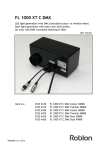
LINEARdrives are highly integrated, enclosed and easy-to-configure direct voltage controlled
driver/controllers for low-power, indoor LED lighting applications requiring up to 24A.
LINEARdrives can be integrated in a network or used as standalone devices. ShowMaster,
supported on all eldoLED driver/controllers, allows you to upload show sequences for use in
standalone mode. You can create and manage your own show sequences with the eldoLED
TOOLbox and freely available PC software.
LINEARdrives are DMX, DALI and LedSync compatible, allowing up to 15-bit dimming and colour control and bidirectional communication for driver configuration and temperature read-out.
Figure 1.1: LINEARdrive
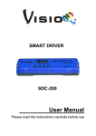
1.1 Setup is a breeze!
Configure the LINEARdrive over its intuitive, 3-button user interface with display. The easy-tonavigate menu allows you to set parameters such as number of channels, DMX or DALI settings for networked mode and show/colour/dim values for standalone operation. You can also
lock the driver’s configuration and perform a test run of the connected LED groups.
1.2 Robust thermal management
Built-in over temperature protection protects the LINEARdrive against overheating.
9
1.3 ShowMaster
ShowMaster, supported on all eldoLED driver/controllers, allows you to upload show sequences for use in standalone mode. You can create and manage your own show sequences with
the TOOLbox and freely available PC software.
Visit www.eldoled.com/software to download the freely available PC software.
Figure 1.2: Creating your own show sequences with eldoLED PC software
1.4 Low EMI
LINEARdrive’s EMI is very low due to the implementation of slew-rate controlled dimming and
shielded conductors.
10
1.5 Easy to connect
Connecting the LINEARdrive is self-explanatory: the spring-cage connectors for LEDs, power
and network leads are all clearly marked.
Figure 1.3: Clearly marked connectors on the LINEARdrive
Strain reliefs prevent leads from being pulled out by accident.
TC
Group 1
Group 1 GND
Ext in
Ext in +
DALI in +
DALI in DALI out +
DALI out DMX in +
DMX in DMX in shield
LedSync out +
LedSync out LedSync shield
Group 2 -
LINEARdrive 720D
12-28V / 24A Direct voltage controlled LED driver
Group 2 GND
Group 3 Group 4 GND
Group 4 Group 3 GND
Figure 1.4: Strain reliefs on the LINEARdrive
11
12
2 Mounting the driver/controller
2.1 Realizing the right thermal conditions
LINEARdrive 180 can be operated without a heat sink, as its own heat generation always stays
within an acceptable temperature range.
Being the most powerful of its range, LINEARdrive 720 must be mounted onto a heat sink. To
ensure the best possible contact between the LINEARdrive 720 and the heat sink, LINEARdrive 720 features a dual heat spreader.
The general rule of thumb you can use when calculating a heat sink’s required dissipating capabilities is that an eldoLED driver/controller adds 10% at the very most to the power consumption of the connected LEDs. In other words, if the connected LEDs consume 90W, the driver/
controller will add a maximum of 9W: the heat sink will have to be able to deal with a total of
99W.
It is recommended to keep ambient temperature values between -20°C and +50°C (-4°F and
+122°F). If the ambient temperature exceeds these limits and causes the LINEARdrive to heat
up above normal operating values, its built-in overheating protection will make it shut down.
2.2 Removing the cover
To remove the driver/controller’s cover:
1. Take hold off the driver/controller as indicated by arrow 1 in Figure 2.1: “Removing the
cover”.
2. Pull the cover off the base unit in the upward movement indicated by arrow 2.
2
0
t
len
iva
°C
qu p
50
-e
LV % ty to +
SE : 99 °C
0
: -2 5°C
t a : +6
Tc
13
M
rive
Rd
EA
LIN
r
olle
ontr
r/C
rive
47
DD
615
LE
, EN
ent
llig
003
Inte 1347 IEC61
6
,
IEC 5015
5
EN
1
Figure 2.1: Removing the cover
13
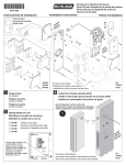
2.3 Preparing the mounting surface
LINEARdrive can be mounted onto wood, plastic or metal. If you need to pre-drill mounting
holes into the mounting surface or heat sink:
1. Remove the LINEARdrive’s cover as shown in 2.2 “Removing the cover”.
2. Place the LINEARdrive onto the mounting surface in the desired position.
3. Indicate the position of the mounting holes on the surface by drawing them through
the LINEARdrive’s M4 mounting holes with a pencil.
M4 mounting hole
M4 mounting hole
TC
Group 1
Group 1 GND
Group 2 -
Ext in Ext in +
DALI in +
DALI in DALI out +
DALI out DMX in +
DMX in DMX in shield
LedSync out +
LedSync out LedSync shield
Group 2 GND
LINEARdrive 720D
Group 3 Group 3 GND
12-28V / 24A Direct voltage controlled LED driver
M4 mounting hole
Group 4 Group 4 GND
M4 mounting hole
Figure 2.2: LINEARdrive’s mounting holes
4. Take away the LINEARdrive and pre-drill the screw holes in the mounting surface.
The LINEARdrive’s mechanical dimensions are listed in appendix A “Specifications”.
2.4 Fastening the driver/controller to the surface
To fasten the driver/controller to the mounting surface:
1. The driver/controller has four mounting holes suited for M4 screws. Make sure you
have four screws that are appropriate for the surface that you want to mount the driver/
controller onto. Use mounting screws with a minimum length of 15mm.
2. Place the driver/controller in the desired location, matching the LINEARdrive’s mounting holes with the predrilled screw holes on the mounting surface.
3. With a screwdriver, fasten the driver/controller to the surface.
The LINEARdrive must be mounted according to the requirements of local
legislation.
14
It is recommended to mount eldoLED products in accordance with the IPCA-620 standards.
TC
Group 1
Group 1 GND
Ext in
Ext in +
DALI in +
DALI in DALI out +
DALI out DMX in +
DMX in DMX in shield
LedSync out +
LedSync out LedSync shield
Group 2 -
LINEARdrive 720D
12-28V / 24A Direct voltage controlled LED driver
Group 2 GND
Group 3 Group 4 GND
Group 4 Group 3 GND
Figure 2.3: Fastening the mounting screws
15
16
3 Connecting the driver/controller
This chapter tells you how to connect the power supply, network and LED leads to the driver/
controller, and lists information regarding wire sizes.
3.1 Required wire sizes
The following diagram lists the required wire sizes for the various connectors and the length of
insulation material you need to strip away from the leads.
The diameter of the wires including insulation material should be the same
for all wires on the same side. The diameter of the wires including insulation
material should be between 0.99mm and 3.12mm.
3.1.1 LINEARdrive 180
Connector
Wire core
diameter in mm
AWG
Insulation material to be
stripped away in mm
VDC
0.14 - 0.5
26 - 20
11
EXT in
0.5 - 1.5
20 - 16
9
DMX in
0.5 - 1.5
20 - 16
9
LedSync thru
0.5 - 1.5
20 - 16
9
LED (Group x)
0.14 - 1
26 - 18
10
17
3.1.2 LINEARdrive 720
Connector
Wire core
diameter in mm
AWG
Insulation material to be
stripped away in mm
VDC
0.14 - 0.5
26 - 20
11
EXT in
0.14 - 0.5
24 - 20
9
DALI in
0.14 - 0.5
24 - 20
9
DALI out
0.14 - 0.5
24 - 20
9
DMX in
0.14 - 0.5
24 - 20
9
LedSync out
0.14 - 0.5
24 - 20
9
LED (Group x)
0.14 - 1
26 - 18
10
3.2 Removing the strain reliefs
Strain reliefs prevent leads from being pulled out by accident. Before you can connect any
leads, you need to remove the strain reliefs.
To remove the strain reliefs:
1. Remove the cover as described in 2.2 “Removing the cover”.
2. Use a phillips crosshead screwdriver to unscrew the screws that fasten the strain reliefs to the base unit.
3. Take the strain reliefs out.
18
1
2
TC
Group 1
Group 1 GND
Ext in
Ext in +
DALI in +
DALI in DALI out +
DALI out DMX in +
DMX in DMX in shield
LedSync out +
LedSync out LedSync shield
Group 2 -
LINEARdrive 720D
12-28V / 24A Direct voltage controlled LED driver
Group 2 GND
Group 3 Group 4 GND
Group 4 Group 3 GND
Figure 3.1: Removing the strain reliefs
19
3.3 Connecting the leads
This section first explains in general how to go about connecting a lead to the LINEARdrive,
and then goes on to describe the specific springcage connectors.
To connect the leads (power, network, LED, etc.):
1. Locate the correct connector for the lead that you wish to connect. The connectors are
clearly marked on the base unit.
2. Strip away the insulation material from the tip of the lead. Refer to the tables in 3.1 “Required wire sizes” for information on the length of insulation material that you need to
strip away. Stripping away too little insulation material can result in a poor or loose connection.
3. Using a small flat screw driver (2mm wide) or your fingernail, push down the top of the
springcage connector.
4. While pressing down the top of the springcage connector, insert the stripped part of
the lead into the connector.
5. Release the top of the springcage connector.
6. Repeat steps 1 through 5 for all leads that you wish to connect.
1
Ext in
Ext in +
DALI in +
DALI in DALI out +
DALI out DMX in +
DMX in DMX in shield
LedSync out +
LedSync out LedSync shield
2
LINEARdrive 72
12-28V / 24A Direct voltage controlled
Figure 3.2: Connecting the leads
The LINEARdrive’s wiring must always meet the requirements of local legislation.
20
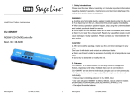
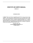
3.3.1 Locating the right connector
The figures below show the wiring diagrams for the LINEARdrive Display 180 and 720 and are
followed by a short explanation of the LINEARdrive’s springcage connectors.
{
12V-28V DC IN
LED groups
VDC - VDC +
R
Ext in +
Ext in -
TC
LED supply +
DMX in +
DMX in DMX in shield
DMX in +
DMX in -
Ext in Ext in +
Group 1
DMX in shield
Group 2
LINEARdrive 180D
Group 3
12-28V / 6A Direct voltage controlled LED driver
Group 4
LedSync thru +
LedSync thru +
LedSync thru LedSync thru shield
R
R
R
LED sup
R
G
B
W
LedSync thru LedSync shield
Figure 3.3: LINEARdrive Display 180 wiring diagram
{
12V-28V DC IN
VDC - VDC +
R
R
R
R
EXT in +
EXT in +
TC
DALI in +
DALI in DALI out +
DALI out DMX in +
DMX in DMX in shield
LedSync out +
LedSync out LedSync shield
Ext in Ext in +
DALI in +
DALI in DALI out +
DALI out -
Group 1
Group 1 GND
R
Group 2 -
G
B
Group 2 GND
LINEARdrive 720D
Group 3 Group 4 GND
12-28V / 24A Direct voltage controlled LED driver
Group 4 Group 3 GND
W
LGND
-
DMX in +
DMX in DMX in Shield
LedSync out +
LedSync out LedSync shield
Figure 3.4: LINEARdrive Display 720 wiring diagram
3.3.1.1 Connecting power leads
Connect the positive voltage supply wire of the 12V-28V DC power supply to the VDC+ connector, and the negative voltage supply wire to the VDC- connector.
The power leads should have an insulating capacity of 100 volts or more, and the leads’ insulation must be able to withstand temperatures of 85°C or more.
21
3.3.1.2 Connecting an external input device
It is possible to connect an external control device to the LINEARdrive. You can connect:
• a 10kΩ potentiometer, allowing you to turn on/off and dim the light
• a 0...10V control device, allowing you to turn on/off and dim the light
• an external switch allowing you to select another show sequence
To connect one of these control devices to the LINEARdrive, connect the device’s positive lead
to the EXT in+ connector and its negative lead to the EXT in- connector.
3.3.1.3 Connecting DMX network cabling
The data wires must be connected to the DMX and LedSync connectors.
For data input on both LINEARdrive 180 and LINEARdrive 720, connect the network cable’s
data+, data- and shielding wire (the orange, orange/white and brown wire in a CAT5 cable) to
the DMX in+, DMX in- and DMX in shield connector respectively.
For data output on LINEARdrive 180, connect the network cable’s data+, data- and shielding
wire (the orange, orange/white and brown wire in a CAT5 cable) to the LedSync thru+, LedSync
thru- and LedSync thru shield wire respectively.
For data output on LINEARdrive 720, connect the network cable’s data+, data- and shielding
wire (the orange, orange/white and brown wire in a CAT5 cable) to the LedSync out+, LedSync
out- and LedSync out shield wire respectively.
LedSync is the eldoLED proprietary communication protocol that is 100% DMX512A-compatible, and enables additional features such as a 15-bit control resolution and bidirectional communication for driver configuration and temperature read-out.
For DMX wires, use CAT5 Shielded Twisted Pair cabling or equivalent.
3.3.1.4 Connecting DALI network cabling
The data wires must be connected to the DALI in and DALI out connectors.
For data input, connect the network cable’s data+ and data- wire to the DALI in+ and DALI in connector respectively.
For data output, connect the network cable’s data+ and data- wire to the DALI out+ and DALI
out - connector respectively.
22
3.3.1.5 Connecting LED groups
Connect the leads of your LED groups
• to the LED supply and Group x connectors on the LINEARdrive 180’s right side
• to the Group x and Group x GND connectors on the LINEARdrive 720’s right side
R
TC
R
G
B
W
Group 1
Group 2
Group 3
ver
Group 4
R
LED sup
LED supply +
D
R
R
Figure 3.5: Connecting LED groups on LINEARdrive 180
R
R
Group 2 -
G
B
ive 720D
Group 3 Group 4 GND
ge controlled LED driver
Group 4 Group 3 GND
R
R
+
TC
Group 1
Group 1 GND
Group 2 GND
R
W
-
LGND
Figure 3.6: Connecting LED groups on LINEARdrive 720
Go to www.ledcode.com to get a free wiring diagram for your LED application.
The length of the wires between the LINEARdrive and the light engine (the
LEDs) should not exceed 3m. Beyond this length, the resolution and contrast
rate cannot be guaranteed.
23
3.4 Replacing the strain reliefs
To replace the strain reliefs:
1. On both sides of the LINEARdrive, make sure the leads run between the strain reliefs’
screw holes.
2. Place the strain relief over the leads.
3. Fasten the strain reliefs’ screws.
4. Replace the LINEARdrive’s cover.
2
1
TC
Group 1
Group 1 GND
Ext in
Ext in +
DALI in +
DALI in DALI out +
DALI out DMX in +
DMX in DMX in shield
LedSync out +
LedSync out LedSync shield
Group 2 -
LINEARdrive 720D
12-28V / 24A Direct voltage controlled LED driver
Group 2 GND
Group 3 Group 4 GND
Group 4 Group 3 GND
Figure 3.7: Fastening the strain reliefs
24
4 Configuring the driver/controller
Configure the driver/controller over its intuitive, 3-button user interface with display. The easyto-navigate menu allows you to set parameters such as number of LED groups, DMX or DALI
network settings for networked mode and show/colour/dim values for standalone operation.
You can also lock the driver’s configuration and perform a test run of the connected LED
groups.
This chapter explains how to work with the menu buttons and display, and lists the various
menu items and selectable values.
4.1 Working with the menu buttons and display
The driver/controller features three menu buttons (M, - and +) with which you can navigate the
configuration menu. The display above the menu buttons shows the menu item names and values that can be selected for every item.
In order to prevent an unlocked driver/controller’s configuration from being accidentally
changed by objects touching the menu buttons, the menu buttons are sunk into the cover.
For easy access to the buttons when you are doing a complete configuration, it is recommended to remove the cover. If you only need to change one setting, such as changing a colour or
show sequence, you can leave the cover on and press the menu buttons using a pen.
LINEARdrive
Intelligent LED Driver/Controller
IEC61347
EN55015, IEC61003, EN61547
M
130
SELV-equivalent
: 99% typ
t a : -20°C to + 50°C
Tc: +65°C
Figure 4.1: Intuitive user interface
25
4.1.1 General function of menu buttons
Pressing M
• shows the current mode or the next menu item; use the M button to browse menus
and settings without making any changes.
• saves a changed value.
• at the last menu item turns off the display.
Pressing + or • changes a value (which is only saved when M is pressed).
Accidentally changed a value but haven’t confirmed it yet by pressing M? By
not doing anything and waiting for 8 seconds, the display will turn itself off
without changing the value.
If you are in a menu and want to change to another menu, do not press any
buttons for at least 8 seconds so the display turns off, and subsequently
press the button combination for the menu you want to change to.
4.2 Main menu items
The very first time the power is connected to the LINEARdrive, the display will show the
LINEARdrive type, e.g. LINEARdrive 720, for a couple of seconds. Next, the display shows
“SET MODE”. You need to set the mode of operation first, before you can move on to the
other menu items.
If the power is interrupted to a LINEARdrive that has already been configured, the display will
only show the LINEARdrive type when the power comes back on, but will not go to the Set
Mode menu, as the LINEARdrive’s configuration has been saved to memory.
Proceed as follows to configure your LINEARdrive:
1. Set the mode of operation (COLR, SHOW, DMX or DALI) in the mode selection menu.
2. Set the LED group configuration in the LED menu.
3. Configure the operation mode you have chosen in step 1 (COLR, SHOW, DMX or DALI).
Except for the configuration menus SET MODE, LED, COLR/SHOW/DMX/DALI and LED
CODE, a number of other menus give the LINEARdrive some additional features:
• TEST: lets you perform a test run of the connected LEDs
• LOCK: lets you softlock or hardlock the LINEARdrive’s configuration
• RESET: lets you reset the LINEARdrive to the factory default settings
26
4.2.1 Setting the mode of operation
In the mode selection menu, you can set the mode of operation for your driver/controller:
• COLR MODE: lets you set a colour for standalone operation.
• SHOW MODE: lets you set a show sequence for standalone operation.
• DMX MODE: lets you configure DMX related settings (start address, network resolution, termination) for networked operation.
• DALI MODE: lets you view (!) DALI related settings (start address, network resolution,
termination) for networked operation. Note that you do not actively configure DALI settings: these are automatically set by the DALI master. This mode is only available on
the LINEARdrive 720.
To enter the mode selection menu:
1. The very first time the power is connected to the LINEARdrive, the display will show
the LINEARdrive type for a couple of seconds and then automatically enter the SET
MODE menu.
When you want to change the mode of operation of a previously configured LINEARdrive, press the M button for five seconds to enter the SET MODE menu.
The display shows “SET” - “MODE” followed by the name of the first mode (COLR).
2. Press + or - until the display shows the mode you want your driver/controller to operate
in: COLR, SHOW, DMX or DALI.
3. Press the M button to save your selection. The display will turn off after you have
pressed the M button.
M (5 sec)
Set mode
SET MODE
M
-
/
+
COLR
SHOW
DMX
display off
DALI
Figure 4.2: Setting the mode of operation
The display also turns off after 8 seconds of inactivity. To enter the Mode menu again,
repeat the aforementioned sequence.
27
After you have confirmed COLR MODE as the mode of operation, it is recommended to set the LED groups via the SETUP menu first, before entering
the COLR menu to set the colour of your choice.
For information on how to configure the LED groups, see 4.2.2 “Configuring
LED groups” .
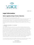
4.2.2 Configuring LED groups
In the SETUP menu, you can configure the LED groups and an external input device.
M + +
LED groups
/
LED
-
M
1-1L
2-2L
3-3L
4-4L
2-4L
1-4L
+
RGB
RGBW
RGBA
RRGB
RGGB
CCWW
CWWW
External input
EXT
INP
M
-
/
+
OFF
POTM
10V
SWIT
display off
Figure 4.3: Configuring the LED groups
28
To enter the SETUP menu:
1. Press the M and + button simultaneously.
2. The display displays LED. This menu option configures the LED groups. Possible values are:
a. 1-1L: one DMX channel is used for one LED group (group 1). The other LED
group connectors are disabled.
b. 2-2L: two DMX channels are used for two LED groups, the group 1 and group 2
connector. Group 3 and 4 are disabled.
c. 3-3:L: three DMX channels are used for LED groups 1, 2 and 3. Group 4 is disabled.
d. 4-4L: one DMX channel is used per LED group.
e. 2-4L: two DMX channels are used for four LED groups, one for group 1 and 2,
the other for group 3 and 4.
f.
1-4L: one DMX channel is used for four LED groups.
g. RGB: 3 DMX channels are used for three LED groups: one channel for red
LEDs, one for green LEDs and one for blue LEDs.
h. RGBW: four DMX channels are used for four LED groups: one channel for red
LEDs, one for green LEDs, one for blue LEDs and one for white LEDs.
i.
RGBA: four DMX channels are used for four LED groups: one channel for red
LEDs, one for green LEDs, one for blue LEDs and one for amber LEDs.
j.
RRGB: three DMX channels are used for four LED groups: two channels for red
LEDs, one for green LEDs and one for blue LEDs.
k. RGGB: three DMX channels are used for four LED groups: one channel for red
LEDs, two for green LEDs and one for blue LEDs.
l.
CCWW: one DMX channel is used for two LED groups with the same colour and
one DMX channel is used for two LED groups consisting of white LEDs only.
m. CWWW: one DMX channel is used for one LED group and one DMX channel is
used for three LED groups consisting of white LEDs only.
3. Press M to confirm the LED group configuration of your choice.
4. The EXT INP menu item allows you to configure the LINEARdrive for use with an external input device such as a 10kΩ potentiometer (POTM), a 0...10V control device
(10V) or a show switch (SWIT). The first two allow you to turn on/off and dim the light,
the last one to select another show sequence. Confirm your choice by pressing M.
When the EXT INP menu item is set to another value than OFF, but no device is
connected to the EXT connectors, the driver/controller will not yield the optimum
light output.
29
4.2.3 Configuring the operation mode ‘COLR’
In COLR mode, you can set your LED application’s colour for standalone (i.e. non networked)
operation. To change the COLR settings:
1. Press M to enter the COLR menu. Your options in the COLR menu depend on the way
you have configured your LED groups in the SETUP menu. Below you will find the
COLR menu options for the corresponding LED group configurations.
1-1L and 1-4L
1-1L: one DMX channel is used for one LED group (group 1). The other LED group
connectors are disabled.
1-4L: one DMX channel is used for four LED groups. This means that all four groups
have light output.
INT (intensity) lets you set the intensity of the light output: 255 is full on, 0 is off.
M
Intensity
INT
-
/
+
0...255
M
display off
Figure 4.4: COLR settings for 1-1L and 1-4L
2-2L and 2-4L
2-2L: two DMX channels are used for two LED groups, the group 1 and group 2 connector. Group 3 and 4 are disabled.
2-4L: two DMX channels are used for four LED groups, one for group 1 and 2, the other for group 3 and 4.
INT (intensity) lets you set the intensity of the light output of each channel: 255 is full
on, 0 is off.
M
Group 1 intensity
INT 1
-
/
+
0...255
M
Group 2 intensity
INT 2
-
/
+
0...255
M
display off
Figure 4.5: COLR settings for 2-2L and 2-4L
30
3-3L
3-3L: Three DMX channels are used for LED groups 1, 2 and 3. Group 4 is disabled.
INT (intensity) lets you set the intensity of the light output of each channel: 255 is full
on, 0 is off.
M
Group 1 intensity
INT 1
-
/
+
0...255
M
Group 2 intensity
INT 2
-
/
+
0...255
M
Group 3 intensity
INT 3
-
/
+
0...255
M
display off
Figure 4.6: COLR settings for 3-3L
4-4L
4-4L: one DMX channel is used per LED group. INT (intensity) lets you set the intensity
of the light output of each channel: 255 is full on, 0 is off.
M
Group 1 intensity
INT 1
-
/
+
0...255
M
Group 2 intensity
INT 2
-
/
+
0...255
M
Group 3 intensity
INT 3
-
/
+
0...255
M
Group 4 intensity
INT 4
-
/
+
0...255
M
display off
Figure 4.7: COLR settings for 4-4L
31
CCWW or CWWW
CCWW: one DMX channel is used for two LED groups with the same colour and one
DMX channel is used for two LED groups consisting of white LEDs only.
CWWW: one DMX channel is used for one LED group and one DMX channel is used
for three LED groups consisting of white LEDs only.
M
Color / white
CW
-
/
+
0...1023
M
Intensity
INT
-
/
+
0...255
M
display off
Figure 4.8: COLR settings for CCWW or CWWW
CW lets you set the proportion of colour to white, and INT (intensity) lets you set the
intensity of the light output: 255 is full on, 0 is off.
32
RGB / RRGB / RGGB
RGB: 3 DMX channels are used for three LED groups: one channel for red LEDs, one
for green LEDs and one for blue LEDs.
RRGB: 3 DMX channels are used for four LED groups: two channels for red LEDs,
one for green LEDs and one for blue LEDs.
RGGB: 3 DMX channels are used for four LED groups: one channel for red LEDs, two
for green LEDs and one for blue LEDs.
HUE lets you set the colour: By pressing + or - you actually ‘walk’ along the sides of
the colour triangle shown below, which is based on the CIE diagram. By pressing M
you confirm the colour of your choice. Then, INT lets you set the brightness of the chosen colour.
Green
Red
Blue
Figure 4.9: Setting the colour
M
HUE
HUE
-
/
+
0...1535
M
Intensity
INT
-
/
+
0...255
M
display off
Figure 4.10: COLR settings for RGB, RRGB or RGGB
33
RGBW / RGBA
RGBW: 4 DMX channels are used for four LED groups: one channel for red LEDs, one
for green LEDs, one for blue LEDs and one for white LEDs.
RGBA: 4 DMX channels are used for four LED groups: one channel for red LEDs, one
for green LEDs, one for blue LEDs and one for amber LEDs.
M
HUE
HUE
-
/
+
0...1535
M
White
WHIT
-
/
+
0...255
M
Intensity
INT
-
/
+
0...255
M
display off
Figure 4.11: COLR settings for RGBW or RGBA
HUE lets you set the colour: By pressing + or - you actually ‘walk’ along the sides of
the colour triangle shown below, which is based on the CIE diagram. By pressing M
you confirm the colour of your choice. Then, WHITE lets you add white or amber (you
‘walk’ towards the white center of the colour triangle). Finally, INT lets you set the intensity of the light output.
Green
Green
White
Red
Blue
Red
Blue
Figure 4.12: Setting the colour (left) and adding white or amber (right)
34
4.2.4 Configuring the operation mode ‘SHOW’
Your driver/controller comes with 9 default or a number of custom show sequences. Your LED
application can run these show sequences
• when the LED application is not part of a network (standalone operation).
• when no DMX signal is received over the network
In SHOW mode, you can choose a show sequence and set this sequence’s speed and intensity
i.e. brightness.
To change the SHOW settings:
1. Press M to enter the SHOW menu.
M
Show
SHOW
-
/
+
00...20
M
Speed
SPD
-
/
+
-99...99
M
Intensity
INT
-
/
+
0...255
M
display off
Figure 4.13: Configuring show settings
a. SHOW allows you to select a different show sequence. LINEARdrive can contain up to 20 show sequences. Show sequences can be uploaded to the driver/
controller at the factory, or with a TOOLbox and freely available PC software
(downloadable at www.eldoled.com/software). The latter also let you create
and manage your own show sequences.
b. SPD (speed) allows you to change the speed of the selected show sequence.
Possible range is -99 through 99, with 0 representing the show sequence’s default speed, -99 twice as slow and 99 twice as fast.
c. INT (intensity) allows you to change the intensity of the selected show sequence. Possible range is 0 (off) through 255 (full on).
2. When a changed menu option is saved, the next menu option is automatically displayed on the display.
When you’ve reached the last menu option and press M, the display turns off. The display also turns off after 8 seconds of inactivity. To enter the Show menu again after the
display has turned off, repeat the aforementioned sequence.
35
4.2.5 Configuring the operation mode ‘DMX’
In DMX MODE, you can set LINEARdrive’s network start address and its network resolution.
M
M
DMX address
DMX ADDR
-
/
DMX address
+
DMX ADDR
1...512
M
M
/
+
1...512
M
Network resolution
NETW RES
-
-
/
Network resolution
+
8 BT
16 BT
display off
NETW RES
M
-
M
-
/
+
YES
NO
Network setup
NETW SET
+
8 BT
16 BT
DMX termination
TERM
/
-
/
+
AUTO
MANU
M
display off
Figure 4.14: Configuring DMX network settings for the
LINEARdrive 180 (left) and the LINEARdrive 720 (right)
To change the DMX settings:
1. Press M to enter the DMX menu.
2. Press M to browse the DMX menu options. Depending on the LINEARdrive version,
these are DMX ADDR (DMX address), NETW RES (network resolution), TERM (DMX
termination; only on LINEARdrive 720) and NETW SET (network setup; only on LINEARdrive 720).
When you reach the required menu option, press + or - to change its value and M to
save the changed value. Pressing M after the last menu option exits the configuration
and turns off the display.
a. DMX ADDR allows you to select a network start address for your driver/controller. Value range is 1 through 512.
b. NETW RES allows you to set the network resolution for your driver/controller to
8 or 16 bit. Note that 16 bit allows much smoother dimming and more accurate
colour mixing.
c. TERM allows you to enable termination on your driver/controller.
d. NETW SET allows you to decide whether you want the network start address
assigned automatically (AUTO), or if you want to set it manually (MANU).
36
ONLY enable termination if the driver/controller is the last driver/controller on the
network cable of a bussed network architecture.
4.2.6 Viewing the settings of operation mode ‘DALI’
In DALI MODE, you can view the DALI network settings that have been assigned to your LINEARdrive.
To read out the LINEARdrive’s DALI settings:
1. Press M to enter the DALI menu.
2. Press M to browse the DALI network data:
X BAL shows the number of ballasts, pressing M again will tell you if an address has
been set (ADDR SET) or not (NO ADDR)
Pressing M after the last menu option exits the configuration and turns off the display.
M
DALI
DALI
M
Nr. of ballasts
X BAL
M
NO
ADDR
ADDR
SET
M
M
display
off
display
off
Figure 4.15: Viewing DALI network settings
37
4.2.7 Locking the configuration
You can ensure that your driver/controller’s settings are not changed by locking its configuration. You can choose
• not to lock the configuration: everyone with access to the driver/controller can change
its settings.
• soft-lock the configuration: you can only enter the SHOW, COLR or TEST menu or reset the driver/controller to its factory defaults.
• hard-lock the configuration: none of the driver/controller’s settings can be changed.
There is no way to get back into the driver/controller’s configuration once it has
been hard-locked, you can only reset the driver/controller to its factory defaults!
Only activate the hard-lock after careful consideration!
M + +
(5 sec)
Lock driver
-
LOCK
M
/
+
NO
SOFT
HARD
display off
Figure 4.16: Locking and unlocking the driver/controller’s configuration
To lock the driver/controller’s configuration:
1. Press M and + simultaneously for 5 seconds.
2. Press + or - until the display correctly reflects your choice:
a. NO (do not lock driver/controller)
b. SOFT (soft-lock the driver/controller)
c. HARD (hard-lock the driver/controller).
3. Press M to confirm your selection. The display turns itself off after you have confirmed
your choice.
38
4.2.8 Unlocking a soft-locked driver/controller
To unlock a soft-locked driver/controller and regain full access to all menus:
1. Press M and + simultaneously for 5 seconds.
2. Press + or - until the display correctly reflects your choice:
a. YES (the driver/controller remains soft-locked)
b. NO (the driver/controller is unlocked)
3. Press M to confirm your selection. The display turns itself off after you have confirmed
your choice.
4.2.9 Carrying out a test run
You can carry out an RGBW test run with fade for each channel, to check if (a) all LEDs are
fully functional (b) you have correctly configured your LED groups in the SETUP menu.
To carry out the test run:
1. Press M, - and + simultaneously.
2. The connected LED groups are lit as follows:
for one second, LED group 1 (R) is lit
for one second, LED group 2 (G) is lit
for one second, LED group 3 (B) is lit
for one second, LED group 4 (W) is lit
for one second, LED group 1, 2, 3 and 4 (RGBW) are lit at the same time
- this sequence is repeated once more
M +
-
+
+
Test
TEST
R 1 sec
G 1 sec
B 1 sec
W 1 sec
RGBW 1 sec
R 1 sec
G 1 sec
B 1 sec
W 1 sec
RGBW 1 sec
display off
Figure 4.17: Carrying out a test run of the connected LEDs
39
4.2.10 Resetting the driver/controller to its factory default settings
To reset the driver/controller to its factory default settings:
1. Press M, - and + simultaneously for 5 seconds.
2. The display shows “RE-” “SET” and “PRES MENU”
3. Press M to carry out the reset, or do not press any button for 8 seconds - this allows
you to exit the menu without actually carrying out the reset.
M +
-
+
+
(5 sec)
Reset
RE - SET
PRES MENU
Press menu
M
display off
Figure 4.18: Resetting the driver/controller to its factory default settings
40
A Specifications
Electrical data
• Current:
LINEARdrive 180: up to 6A (1.5A per channel)
LINEARdrive 720: up to 24A (6A per channel)
• Power output:
LINEARdrive 180: up to 180 watts
LINEARdrive 720: up to 720 watts
• Operating supply voltage range: 12V-28V DC
• Processor: eldoLED FluxLogic 850 Series
• Independent LED groups: up to 4
• Reverse polarity protection
Certifications
• CE: IEC 61347, EN 55015, IEC 61003, EN 61547
Dimensions
• LxWxH: 153 mm x 50 mm x 23 mm / 6.02” x 1.97” x 0.91”
LINEARdrive
Intelligent LED Driver/Controller
IEC61347
EN55015, IEC61003, EN61547
M
130
SELV-equivalent
: 99% typ
t a : -20°C to + 50°C
Tc: +65°C
Figure A.1: The LINEARdrive’s dimensions
Dynamic effects
• Hydradrive Algorithm Based Modulation
• Control of channel 1 (R), 2 (G), 3 (B) and 4 (W/A):
0 - 100% in 15-bit set point resolution
• Contrast ratio: up to 2,000:1
41
Environmental ratings
• Ta range: from -20°C to +50°C (from -4°F to +122°F)
• Tc max: 65°C (149°F)
• Theatsink max: 60°C (140°F)
• Relative humidity: non-condensing
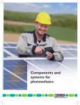
Mechanical dimensions
• The illustration below shows the mechanical dimensions in mm:
21.5
30
10
110
4.2 (4x)
Figure A.2: LINEARdrive’s mechanical dimensions
Mounting data
• Mounting orientation: any
• Mounting holes: suited for M4 screws (4)
Network control
• Network input: USITT DMX512A, LedSync or DALI (DALI only on LINEARdrive 720)
• Network output: LedSync, DALI (DALI only on LINEARdrive 720)
• Network input/output: based on RS485 specification
• DMX/LedSync-in update rate: 8ms
• Network resolution: 8 or 16 bit, configurable over menu buttons
• Network channels used by driver in 8-bit resolution: 4
• Network channels used by driver in 16-bit resolution: 8
• Communication: bidirectional for driver configuration and temperature read-out
• Configuration: via menu buttons and display or via TOOLbox and freely available PC
software
ShowMaster
• Nine standard shows or up to 20 customer-defined shows set at factory
• User-defined shows (ShowMaster): up to 20 shows, via TOOLbox and PC software
• Show selection: via menu buttons
42
Spring cage connectors LINEARdrive 180
• VDC: + and - (2)
• EXT in: + and - (2) for 10kOhm potentiometer, 0-10V or show switch
• DMX in: +, - and shield (3)
• LedSync thru: +, - and shield (3)
• LED groups and LED supply: group 1 through 4 and LED ground (5)
Spring cage connectors LINEARdrive 720
• VDC: + and - (2)
• EXT in: + and - (2) for 10kOhm potentiometer, 0-10V or show switch
• DALI in: + and - (2)
• DALI out: + and - (2)
• DMX in: +, - and shield (3)
• LedSync out: +, - and shield (3)
• LED groups: GND and - for group 1 through 4 (8)
TC
Group 1
Group 1 GND
Group 2 -
Ext in Ext in +
DALI in +
DALI in DALI out +
DALI out DMX in +
DMX in DMX in shield
LedSync out +
LedSync out LedSync shield
Group 2 GND
LINEARdrive 720D
Group 3 Group 4 GND
12-28V / 24A Direct voltage controlled LED driver
Group 4 Group 3 GND
Figure A.3: Clearly marked connectors
Thermal data
• Cooling: passive (integrated heat spreader). Dual heat spreader on LINEARdrive 720
ensures ease of mounting onto required heat sink.
• Required heat sink for LINEARdrive 720: heat sink must be able to dissipate 10% of
the power consumed by the connected LED engine. For example, if the connected
LEDs consume a total of 90W, the driver/controller requires a 9W heat sink.
• Built-in protection against overheating of driver/controller
User interface
• Menu buttons: M, - and + (3)
• Display: segmented (4x16)
• Modes: colour/show/DMX/DALI mode (DALI on LINEARdrive720 only)
• Features: setup, lock, reset
43
Wire sizes LINEARdrive 180
• VDC: 0.14mm - 0.5mm (AWG 26 - 20)
• EXT in: 0.5mm- 1.5mm (AWG 20 - 16)
• DMX in: 0.5mm- 1.5mm (AWG 20 - 16)
• LedSync thru: 0.5mm- 1.5mm (AWG 20 - 16)
• LED groups: 0.14mm - 1mm (AWG 26 - 18)
Wire sizes LINEARdrive 720
• VDC: 0.14mm - 0.5mm (AWG 26 - 20)
• EXT in: 0.14mm- 0.5mm (AWG 24 - 20)
• DALI in: 0.14mm - 0.5mm (AWG 24 - 20)
• DALI out: 0.14mm - 0.5mm (AWG 24 - 20)
• DMX in: 0.14mm - 0.5mm (AWG 24 - 20)
• LedSync out: 0.14mm - 0.5mm (AWG 24 - 20)
• LED groups: 0.14mm - 1mm (AWG 26 - 18)
44
45
LINEARdrive Display user manual V1.0
46