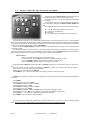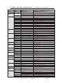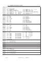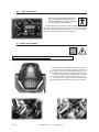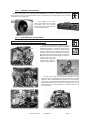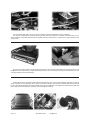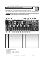
1
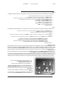
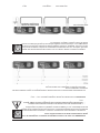
Http://www.coef.it
E-mail:[email protected]
Code ZL-012101-01-DVP-Electronic Ballast
Code ZL-012201-01-DV-Magnetic Ballast
Printed in Aug 2005
Http://www.coef.it - E-mail: [email protected]
This manual has been organized in order support the user, the installer or the maintenance operator of the described unit with those necessary informations for a correct use of the installation and working procedures of the
same unit.The various procedures will be just signalled by indicators (when necessary) evidencing the operation
dangers and the necessity of technical support.
Please find here below a list of symbols and relative meaning:
OPERATOR : Not particulary qualified staff, that can operate when no specific knowledge is required
COEF OPERATOR: Technical staff, qualified and trained by the constructor, for repair and extraordinary
operations.
MECHANICAL OPERATORS: Staff employed in the ordinary mechanical maintenance.
SPECIALIZED MECHANICAL OPERATOR: Qualified staff employed in extraordinary authorized installations and repair.
ELECTRIC OPERATORS: Staff employed in the ordinary electric maintenance.
SPECIALIZED ELECTRIC OPERATORS: Qualified staff employed in extraordinary authorized installations and repairs.
DANGER SIGNAL: Generic dager signal and electric shock danger signal.
GENERAL WARRANTY CONDITIONS
•
•
•
•
•
•
•
•
The guarantee is valid for a period of 12 months from the date of purchase of the equipment.
The guarantee is not valid in case a wrong voltage or frequency is selected.
The parts which are proved to have manufacturing defects are also covered by the guarantee.
The external parts of the equipment, its removable elements and lamps are excluded from the guarantee; for these
parts we recommend to follow the directions supplied by their manufacturers.
The guarantee is not valid in case of tampering or repairs carried out by non-authorized personnel.
The replacement of the equipment during the validity of the guarantee is not provided for.
The transport freights from and to the manufacturer for repairs under guarantee are at Customer’s charge.
When applying for the repair, always mention the serial number and the model of the equipment.
PACKING CONTENTS
Carefully check the contents of the packaging and the completeness of the components. If any of the parts listed hereunder is
missing, please contact your Dealer immediately:
•
•
•
•
•
•
•
MP700 Zoom complet unit.
This user manual.
2 quick lock/release (omega) brackets.
1 connector XLR 3 pin male.
1 connector XLR 3 pin female.
1 connector POWER.
1 safety-chain equipped with two snaps.
PROTECT NATURE.
DO NOT DISPOSE OF THE PACKAGING IN THE ENVIRONMENT.
CAREFULLY KEEP THE BOX AND THE COMPONENTS OF THE PACKAGING FOR ANY DISPLACEMENT
OR RE-SHIPMENT OF THE EQUIPMENT.
Do not leave the packaging elements (polystyrene, nylon, metal parts, etc.) unattended; they might be
dangerous for children.
http://www.coef.it
- [email protected]
Pag. 3
MP700 ZOOM DV with Magnetic Ballast
MP700 ZOOM DVP with Electronic Ballast
Code: ZL-012201-01
Code: ZL-012101-01
3.0
INSTALLATION
The constructor is not be considered responsible in case of:
•
•
•
•
•
•
•
•
•
Improper use of the unit or use by not trained staff
Use in contrast with the directions on work safety
Wrong installation
Defective power supply
Serious lacks in the necessary maintenance
Unauthorized modifications and interventions
Use of spare parts that are not original or not specific for the unit
Total or partial inobservance of instructions
Unusual events
3.1 LAMP MOUNTING OR REPLACING
WARNING: read carefully
•
•
•
•
•
•
•
•
Switch off the projector before operating.
The lamp used in the fixture is a high pressure lamp and must be handled very carefully.
The unit is realized to use only MSR700 lamp; absolutely don’t use other types of lamp.
The lamp must be changed if damaged or deformed by heat.
Wait at least 15 minutes after the projector has been switched off before operating again, in order to let it cool down
and avoid the lamp explosion.
Wear protection gloves and glasses.
Read carefully the lamp builder’s instructions.
Don’t look directly the lamp.
Wait 30 minutes in order to avoid burns.
Unscrew with a cross screwdriver the first screw A for a single turn; unscrew the second one completely B;
unscrew completely the screw A and to remove the cover that supports the lampholder.
Insert delicately the lamp in the projector support, driving it with the round cover.
Pay attention: the lampholder’s wires must correctly reenter in the projector. Block the cover screwing the screws
up ( part. A-B).
http://www.coef.it - [email protected]
Pag. 5
3.2
OPERATING VOLTAGE
WARNING : unplug the fixture from the power supply before operating . The operation must be performed only
by highly specialized staff.
WARNING : The wrong selections of the operating tension and/or frequency compromise the good operation of
the fixture and will immediately invalid the COEF warranty.
3.3
Settings for magnetic ballast Code:ZL-012201-01
Cod. 02E010
The fixture can work at the
following tensions : 230 V~50 / 60 Hz
and 208 V~ 60 Hz (optional). Please
be careful to connect the cable to the
right terminal that is relevant to the
desired tension and frequency; both
on the ballast and on the transformer
located in the MP700Zoom base.
Please
carefully
follow
the
indications shown in the pictures A
and B.
B
A
3.4
Settings for electronic ballast Code:ZL-012101-01
Cod. 02E011
The fixture can work at the following tensions : 100V ~ 60 Hz, 120V ~ 60 Hz, 208 V
~50/ 60 Hz, 230 V ~50 / 60 Hz, 250 V ~50 / 60
Hz.
You can modify the settings following the
needs of the country were the fixture is installed. This operation is easily done by moving
the cable to the right terminal of the electronic board transformer that is located in the
base of the fixture. The ballast (electronic) does not need any adjustment.
We recommend you to update the serigraphy table at the new value.
3.5
PROJECTOR INSTALLATION
To fix the MP700 Zoom is necessary, when the installation has to be
on a raised-from-the ground support, to block the quick lock/release brackets of the unit by means of a screw provided with nut and locknut measuring not less than M10X50, to insert in the central pre-arranged hole on the
fixing bracket.
In addiction to the provided quick lock/release (omega) brackets, in order to guarantee a necessary security and in respect of the actual safety
rules concerning the projectors’ installation, it is compulsory to install a safety-chain, equipped with two snaps, provided with the projector, to connect the MP700 Zoom‘s body to the fixing structure.
ATTENTION: the safety chain, equipped with two snaps which can be
hooked to the two pivots placed under the base of the MP700 Zoom, (see
part. A), must be properly installed and fixed to the supporting structure, in
a way that an incidental givin in of the main bracket would leed to the shortest possible fall of the projector. After such an intervention the safetychain must be replaced with another original part.
ATTENTION: COEF is not responsible for installations not correctly
made or made without respecting the above indications: those installations
are considered dangerous.
Pag. 6
http://www.coef.it
-
[email protected]
4.0 POWER SUPPLY CONNECTIONS
WARNING: In order to guarantee the utmost safety, connect the apparatus only to a properly
earthed mains system.
The projector is designed to work at the tension and frequency indicated by the electrical data label on the rear. Before connecting the projector to the mains, a qualified electrician must check its
conformity.
• The projector must be protect by an adeguated magneto-thermal switch .
• Don't power the unit with a dimmer circuit.
Power : indicated in the the serigraphy table (tollerance: +5% / -10%)
Should there be different electrical characteristics or special steps to be carried out, please contact COEF by
telephone or e-mail.
Supply the projector by connecting it as indicated in picture.
4.1 DMX 512 CONNECTIONS
Connect the projector and the control unit to a wire in conformity with the EIA RS-485 standards: braided bipolar,
shielded, 120 ohm of characteristic impedance, 22-24 AWG, equipped with Cannon 3 Pin XRL plugs. Respect the
DMX 512 signal input and output according to the panel indications. A terminal pin with 120 ohm resistance (¼ Watt
minimum) must be inserted between the terminals 2 and 3 in the last piece of apparatus.
http://www.coef.it
- [email protected]
Pag. 7
5.0
SPECIAL FUNCTIONS AND PROJECTOR ASSIGNMENT
On the front panel of MP700 Zoom you'll find a section for
the additional functions and for setting the projector.
Following the picture, you can see all the offered possibilities in detail.
All operations are to be carried out with the E, F, G, H buttons, respectively indicated as MENU, ENTER, DOWN and
UP.
The display D will inform you about the selected functions.
The 3 A, B, and C leds will allow you to know:
A = reception of the DMX line.
B = lamp ON.
C = errors indicated on the ERR table (see table 6.0).
On switching the projector on, the display will indicate the type of projector and the version of control software
which have been installed. To this purpose, please remember that this type of projector belongs to a new generation
of projectors, designed with the possibility of updating the software version through the normal DMX connection by
means of a programmer deliberately created: UNI-PROG 8.
After the indication MSTR HOME, the projector carries out the RESET and gets ready to be controlled from the
connected console.
The display will indicate 1 as default value. This means that the first channel occupied by the projector will respond to the values sent to channel 1 by the DMX line. This enables us to make MP700 Zoom (which we are installing) completely independent from control or integral with any other installed projector.
General Rules:
Refer to the Table of Section 6.0 in the following page.
By each pressure, Button MENU (E) permits to go backwards by one level.
G and H (DOWN and UP) buttons select functions and sub-functions.
Button F (ENTER) enters the function and confirms a control.
By pressing Button MENU (E) and buttons UP and DOWN (H and G) you can select the menu you have to modify.
Once the wished menu is reached, press Button F (ENTER) to confirm your selection and enter the function.
Press G or H to enter the sub-functions if available.
Always confirm your selection with ENTER.
Press MENU to go out of the function and press again to go back to the starting level.
Example: We installed our projector on the ceiling and for this reason we want the visualization of the display to
be correct.
Press MENU
Press H (UP) 11 times up to “MISC”
Press ENTER the Display will show “RSET”
Press H (UP) twice up to “DSPL”
Press ENTER the Display will show “ONOF”
Press H (UP) once up to “STRV”
Press ENTER the Display will show “STND”; this is the actual configuration state.
Press H (UP) once up to R.E.V..; the blinking point indicate the available configuration.
Press ENTER ...... The Display visualization as been rotated to 180°.
Press MENU 4 times to return to starting MENU.
The indication of the display will automatically come back after 120 sec. and inform on the set starting channel
DMX. If we are now in a sub-function, this automatic device will not assume control.
Pag. 8
http://www.coef.it
-
[email protected]
6.0 MENU, FUNCTION & SUB-FUNCTIONS
MENU
FUNCTION
DMX
1/497
LAMP
TIME
MACH
SUB-FUNCTION
(*) = default value - factory assigned
DESCRIPTION
DMX start channel
Lamp working hours (KH=thousands H=hours)
Lamp working hours reset (confirm by ENTER)
Projector working hours (KH=thousands H=hours)
SHOW - KH, H
RST - GO?
SHOW - KH, H
ERR
E OK
E110
E220
E230
E240
E250
E260
E420
E510
E520
W310
W410
W422
W424
No error
EEPROM failure
Malfunction of the COLOR motor/sensor
Malfunction of the GOBOS motor/sensor
Malfunction of the GOBOS ROT. motor/sensor
Malfunction of the PAN motor/sensor
Malfunction of the TILT motor/sensor
No ignition of the lamp beyond 3 attempts. (break?)
Malfunction encoder PAN
Malfunction encoder TILT
Checksum Setup not valid
Lamp working hours for more than 500 hours
LAMP start beyond 1 attempts (attempt to warmth or exausted lamp)
LAMP off in not standard mode
SHUT
HOME
TEST
ADJ
SET
HOME SHUTTER
TEST SHUTTER
Fine regulation of the closing shutter.
Reserved
COL
HOME
TEST
CSHUT
MODE
ADJ
P1
(*) OFF / ON
(*) MOD1 / MOD2
P 1 / P20
- 49 / 49
-29 / 29
HOME COLOR
TEST COLOR
Color change in black-out position
Color switching or linear wheel motion
Fine regulation of the COLOR position (P1 / P20)
-29 / 29
HOME GOBOS
TEST GOBOS
GOBO change in black-out position
Fine regulation of the NEUTRAL GOBO position
GOBO
HOME
TEST
GSHUT
ADJ
RGOB
HOME
TEST
HOME Rotation GOBOS
TEST Rotation GOBOS
CONV
HOME
TEST
ADJ
HOME Conversion filters
TEST Conversion filters
Fine regulation of the CONVERSION FILTER position
(*) OFF / ON
P1
P1
-99 / 99
FCUS
HOME
TEST
HOME Focus trolley
TEST Focus trolley
ZOOM
HOME
TEST
HOME ZOOM trolley
TEST ZOOM trolley
EFCT
HOME
TEST
ADJ
HOME Prism/Frost
TEST Prism/Frost
Fine regulation of the PRISM position
RPRS
TEST
TEST of the Prism rotation
IRIS
HOME
TEST
HOME Iris
TEST Iris
PAN
HOME
TEST
STRV
ENCO
(*) STND / REV
(*) ON / OFF
HOME PAN movement
TEST PAN movement
Switch movement direction ( DX / SX)
ON/OFF the automatic repositioning of the PAN
TILT
HOME
TEST
STRV
ENCO
(*) STND / REV
(*) ON / OFF
HOME TILT movement
TEST TILT movement
Switch movement direction (UP / DOWN)
ON/OFF the automatic repositioning of the TILT
SCH
CH1 / CH16
LAMP
ONOF
CDMX
RSET
RDMX
DSPL
MISC
SWPT
EDIM
VER
P1
-99 / 35
DMX value for the indicated channel
(*) ON / OFF/ AUTO
(*) NO / YES
Lamp ON / Lamp OFF / LAMP OFF after 1 hour of no change on DMX
LAMP switching on by DMX control
(*) YES / NO
(*) ON / OFF
(*) STND / REV
(*) STND / SWAP
YES / NO
(automatic value)
MASTER HOME (Starting RESET)
MASTER HOME via DMX control
Display on / Display off
180° rotation of the visualization display
Channel control switch PAN / TILT
If YES = Electronic Dimmer ON (Electronic Ballast)
Show the installed software version
http://www.coef.it
- [email protected]
Pag. 9
7.0
CHANNELS AND DIGITAL VALUES
CH
1
2
MODE1
2
MODE2
SHUTTER / STROBE / DIMMER
0-5
SHUTTER closed
6-100
DIMMER from channel 14 value
101-110 DIMMER 0 > 100% Automatic 6 sec.
111-120 DIMMER 100% > 0 Automatic 6 sec.
121-126 DIMMER 0 > 100%
slow
Faster shut down
127-132 DIMMER 0 > 100%
middle
Faster shut down
133-138 DIMMER 0 > 100%
fast
Faster shut down
139-144 DIMMER 100% > 0
slow
Faster open
145-150 DIMMER 100% > 0
middle
Faster open
151-156
157-162
163-168
169-174
175-180
181-186
187-192
193-250
251-255
DIMMER 100% > 0
fast
DIMMER 0 > 100% > 0 slow
DIMMER 0 > 100% > 0 middle
DIMMER 0 > 100% > 0 fast
Strobe lamp from 1 to 6 random
Strobe lamp from 1 to 6 random
Strobe lamp from 1 to 6 random
STROBE Speed adjustment
SHUTTER open
COLOR MODE 1
0-5
Neutral
6 - 15
Yellow
16 - 25
Blue
26 - 35
Magenta
36 - 45
Green light
46 - 55
Orange
56 - 65
Cyano
66 - 75
Pink
76 - 85
Red
86 - 95
Blu light
96 - 105
Green
106 - 115 Wood
116 - 125
126 - 135
136 - 145
146 - 155
156 - 165
166 - 175
176 - 185
186 - 195
196 - 200
201 - 205
206 - 230
231 - 255
White-Yellow
Yellow-Blue
Blue-Magenta
Green light-Orange
Orange-Cyano
Cyano-Pink
Red-Blue light
Blue light-Green
Random full-color (slow)
Random full-color (fast)
CW Rotation adjustment
CCW Rotation adjustment
COLOR MODE 2
0-5
6 - 10
11 - 15
16 - 20
21 - 25
26 - 30
31 - 35
36 - 40
41 - 45
46 - 50
51 - 55
56 - 60
61 - 180
181 - 185
186 - 190
191 - 195
196 - 200
201 - 215
216 - 235
236 - 255
Green
Wood
Positioning
Random fast
Random middle
Random slow
Random very slow
Random very fast
CW Rotation adjustment
CCW Rotation adjustment
111 - 120
121 - 130
131 - 140
141 - 150
151 - 160
161 - 170
171 - 180
181 - 190
191 - 198
199 - 205
206 - 230
231 - 255
GOBO 2 chann.4 controls position
GOBO 3
chann.4 controls position
GOBO 4
chann.4 controls position
GOBO 5
chann.4 controls position
GOBO 6
chann.4 controls position
GOBO 7
chann.4 controls position
GOBO 8
chann.4 controls position
GOBO 9
chann.4 controls position
GOBOS Random fast
GOBOS Random slow
CW Rotation adjustment
CWW Rotation adjustment
Neutral
Yellow
Blue
Magenta
Green light
Orange
Cyano
Pink
Red
Blu light
3
GOBOS
0 - 10
Neutral
1 1- 20
GOBO 1
21 - 30
GOBO 2
31 - 40
GOBO 3
41 - 50
GOBO 4
51 - 60
GOBO 5
61 - 70
GOBO 6
71 - 80
GOBO 7
81 - 90
GOBO 8
91 - 100
GOBO 9
101 - 110 GOBO 1
4
ROTATION GOBOS
0-5
STOP
6 - 255
From 0 to 540° GOBO positioning
6 - 130
CW Rotation adjustment of the GOBO
131 - 255
CWW Rotation adjustment of the GOBO
5
6
7
8
chann.4
chann.4
chann.4
chann.4
chann.4
chann.4
chann.4
chann.4
chann.4
chann.4
controls rotation
controls rotation
controls rotation
controls rotation
controls rotation
controls rotation
controls rotation
controls rotation
controls rotation
controls position
PAN MOVEMENT
PAN MOVEMENT FINE ADJUSTMENT
TILT MOVEMENT
TILT MOVEMENT FINE ADJUSTMENT
9
COLOR FILTER CONVERSION
0 - 79
Neutral
80 - 169
Conversion 3400°K
170 - 255 Conversion 5600°K
10
FOCUS ADJUSTMENT
0 - 255
Linear FOCUS adjustment
11
LINEAR ZOOM ADJUSTEMT
0 - 255
Linear ZOOM adjustment
Pag. 10
http://www.coef.it
-
[email protected]
Faster open
[reg. 0.0-0.5 sec.]
[reg. 0.6-1.5 sec.]
[reg. 1.6-2.5 sec.]
CH
12
EFFECTS (Frost - Prism)
0-5
Neutral
6 - 20
Automatic FROST from 0 to 100% (velocity adjustment)
21 - 40
Automatic FROST from 100% to 0 (velocity adjustment)
41 - 60
Frost
61 - 80
Prism 3 faceted
81 - 170
CW PRISM rotation with velocity adjustment
171 - 255 CWW PRISM rotation with velocity adjustment
13
IRIS
0-5
6 - 130
131 - 150
151 - 170
171 - 190
191 - 210
211 - 230
231 - 250
251 - 255
Open / Neutral
IRIS with manual regolation (100% - 0)
IRIS closed
IRIS 0 - 100%
IRIS 100% - 0
IRIS 0-100%-0 slow
IRIS 0-100%-0 middle
IRIS 0-100%-0 fast
IRIS 0-100%-0 random
DIMMER
0-5
6 - 250
251 - 255
DIMMER Closed
DIMMER regolation
DIMMER Open
14
WARNING: position CHANNEL 1 at a value between 6 and 250, in order to control DIMMER with this channel.
15
16
USE MODE (only Electronic Ballast code 02E011)
0-5
Studio mode
6 - 250
Regolation
251 - 255 Live mode
MOVEMENTS TIME ADJUSTMENT (work on channels 5-7)
0-5
NO delay
6 - 250
adjustment delay
251 - 255 MAX delay
7.1 SPECIAL ACTION
When the lamp control via DMX (CDMX) and the reset via DMX (RDMX) function
have been activated in the configuration menu, it’s possible, by a combination of
the channels values, to control the lamp switch ON/OFF or to allow the projector
MASTER RESET.
Lamp ON via DMX:
CHANNEL 2 = value 0
CHANNEL 3 and CHANNEL 4 = value 0 > 255 > 0
Lamp OFF via DMX:
CHANNEL 2 = value 255
CHANNEL 3 and CHANNEL 4 = value 0 > 255 > 0
MASTER RESET:
CHANNEL 1 = value 0
CHANNEL 2 and CHANNEL 3 = value 0 > 255 > 0
http://www.coef.it
- [email protected]
Pag. 11
8.0
LAMP ADJUSTMENT
• Don’t look directly the beam trough the lens.
• The lamp is pre-regulated by the factory.
Only fine-adjustment. Don’t move the screws
”C” up to upper or lower extremities.
Lamp adjustment is necessary to obtain a uniform and powerful
light beam. Switch on the projector and set the channels without
gobo and colors. Adjust the three screws C until you reach the
ideal condition between power and homogeneity.
9.0 GOBOS REPLACEMENT
WARNING: switch off the projector before operating
Open the cover of MP700 Zoom by the 4 fast screw.
The gobo-wheel of the MP 700 Zoom contains dichroic gobos. They are interchangeable simply by removing the little elastic ring with a screwdriver (see figure).
In order to replace a dichroic gobo with a steel gobo,
put a thick ring between the gobo and the elastic ring.
Insert the chosen gobo and place again the steel
ring, paying attention that it reaches its correct position.
Pag. 12
http://www.coef.it
-
[email protected]
10.0
ORDINARY MAINTENANCE
Ordinary maintenance on the projectors MP 700 Zoom is necessary to maintain the perfect efficiency of the unit and to avoid defects like the low luminosity of the light beam or the elevated
overheating of the equipment.
In the figures you can see
those components that can easily
accumulate dust and grease.
Clean them using a soft cloth and
common glass-cleaners.
10.1
EXTRAORDINARY MAINTENANCE
WARNING: switch off the projector before operating
To make an extraordinary maintenance, it is
necessary the presence of a generic or qualified
mechanical operator, according to the type of the
needed intervention. In order to make its use
easier, we advise you to completely draw out the
mechanic unit of the zoom and focus movements
as follows: disconnect the two motors (connectors
B and C) and the fan (connector D); remove the 4
screws (part. A) and
carefully extract the whole
mechanic unit. Clean carefully the indicated parts.
Once the frame with the Zoom/Focus mechanic unit has
been removed, it is possible to clean the parts which are usually
difficult to reach. Reassemble the Zoom/Focus unit carefully,
being sure in particular that the blade with prism and frost is
positioned between the two lenses of the Zoom/Focus unit.
Remember then to connect again the 2 motors and the fan to
their connectors.
http://www.coef.it
- [email protected]
Pag. 13
You must particularly take care of the sensors which are really fundamental in the unit working.
The sensors are absolutely necessary when a general reset of the projector is needed. If this function is not correctly executed, it will totally compromise the regular working of the projector, at least for the group referred to the
sensor itself.
The sensors of the encoders concerning the PAN and TILT movements are located in the base and in the arm of
the MP700 Zoom respectively. The pictures clearly show how you can reach these components and where you can
correctly operate for their maintenance.
Another place where grease and dust settle is inside the lamp-box. Carry out the following operations in order to
clean: unscrew, but not completely, the 4 screws on the side of the fin unit located on top of the bulb; draw out the full
fin unit; clean the antiheat filter and the parabola of the bulb; assemble the fin unit again by inserting first the part next
to the lamp-board and then the 4 screws in their seat; tighten carefully.
Pag. 14
http://www.coef.it
-
[email protected]
10.2 ELETTRONIC MAINTENANCE
WARNING: switch off the projector before operating
This section is dedicated in detail to the electronic connections between the card and the mechanical components, assembled in the projector. These informations will be absolutely necessary when
the mechanical unit has to be removed from the projector for maintenance and/or repair.
The connections are made using handy connectors and are detailed in figure where you can find indications
about the connection between a specific connector and a specific component of the mechanical unit. This includes
the motors and the sensors of the various effects wheels ( color, gobos, prisms, shutter etc.).
WARNING! An improper use of this documentation made by not specifically qualified staff can damage
irremediably the electronic and/or mechanical components of the projector.
1
Motor SHUTTER / STROBE
15
Sensor PAN
2
Motor COLORE wheel
16
Sensor TILT
3
Motor GOBOS wheel
17
S1
Sensor COLOR wheel
4
Motor GOBOS Rotation
18
S2
Sensor GOBOS wheel
5
Motor EFFECTS wheel
19
S3
Sensor GOBOS Rotation
6
Motor ZOOM
20
ON/OFF Lamp (only Magnetic Ballast version)
7
Motor FOCUS
21
Electronic Ballast connector
8
Motor CONVERSION FILTERS
22
LIGHT Sensor / NTC Sensor
9
Motor IRIS
23
POWER Connector
10
Motor PRISM Rotation
24
Faston GROUND connection
11
Motor TILT
25
DMX IN/OUT
12
Motor PAN
26
Head FAN
13
Encoder TILT
27
Base FAN
14
Encoder PAN
23 - Power connector on board
1-2 12V~ +/- 5%
3-4 27V~ +/- 5%
5-6 27V~ +/- 5%
Blue
Grey
Black
http://www.coef.it
- [email protected]
Pag. 15
11.0
TROUBLESHOOTING
PROBLEM
The projector doesn’t swich on
CAUSE
ACTION
- The power supply is not present
Check if the luminous indicator is lighted
or not.
- The lamp is not working
Replace the lamp.
- The thermal switch is active
Just to wait for little of time.
The projector swiches on but - Wrong DMX configuration
doesn’t answer to commands
Defecting projection
Make sure that the projector is correctly
configurated.
- Defective cables
Replace or repair the DMX cable.
- LED A is off
Check the control unit & DMX cable.
- Defective control unit
Check the control unit by means of other
working projectors.
Technical aid is required.
- The lens is broken
Check that the lens are not broken.
- Dust or grease stored on the all Remove dust or grease stored on lenses.
parts of projector
Projection with halo
- Dust or grease stored on the all Carefully clean the optical group lenses
and the projector components (see “Mainparts of projector
tenance” chapter).
Carefully clean the optical group lenses
The color or other effects doesn’t - Position sensor dirty with dust or and the projector components (see “Maintenance”).
grease
coincide to the selected value.
Technical aid is required.
- Defective motor
- Electronic board
Carefully clean the optical group lenses
and the projector components (see “Maintenance”).
The PAN or TILT movement - Defective motor
doesn’t coincide to the selcted - Electronic board
value
Technical aid is required.
The projector does not carry out - ENCO off in the PAN/TILT confi- Set ON ENCO Function of PAN/TILT configuration menu (cap. 6.0).
the automatic repositioning of the guration menu (cap. 6.0)
PAN or TILT movements.
Pag. 16
http://www.coef.it
-
[email protected]
MP 700 ZOOM
TECHNICAL REFERENCE
Wiring diagram
12-08-2005
Cod.ZL-012
Scheda tecnica
MP 700 ZOOM
Schema elettrico
11.0
PROBLEMI
DIFETTO
Il proiettore non si accende
CAUSA
- Mancanza di alimentazione di rete
RIMEDIO
Verificare l’accensione della spia sull’interruttore di accensione.
Attendere lo sblocco del termico.
- Interrutore termico azionato
Sostituire la lampada.
- Lampada non funzionante
Il proiettore si accende ma - Configurazione DMX errata
non risponde ai comandi
- Se il led A non si accende
Assegnare il valore DMX per il proiettore.
Controllare DMX (cavo, console, ecc.).
Controllare l’unità di pilotaggio con altri
proiettori funzionanti.
- Unità di pilotaggio difettosa
Sostituire i cavi o riparare.
- Cavi di collegamento difettosi
Intervento di assistenza tecnica.
Proiezione difettosa
- La lente o più lenti rotte
- Strati di grasso o polvere sulle lenti
Proiezione con alone
Controllare lo stato delle lenti.
Rimuovere la polvere e/o grasso sulle lenti.
- Strati di grasso e/o polvere su tutte le Effettuare una accurata pulizia di tutte le
parti del proiettore (vedi capitolo manutenparti del proiettore
zione).
Il colore o altri effetti non - Sensori di posizione sporchi
corrispondono al valore
impostato
- Motore difettoso
- Scheda elettronica
Il movimento del PAN o
del TILT non segue i valori - Motore difettoso
- Scheda elettronica
impostati
Effettuare una accurata pulizia di tutte le
parti del proiettore (vedi capitolo manutenzione).
Intervento di assistenza tecnica.
Intervento di assistenza tecnica.
Il proiettore non esegue il - Configurazione menu PAN o TILT e Vedi tabella paragrafo 6.0 per abilitare il
riposizionamento ai canali del PAN e/o del
riposizionamento
auto- sottofunzione ENCO a OFF
TILT.
matico per il movimento
PAN o TILT
Intervento di assistenza tecnica.
Per altri problemi contattare:
[email protected]
[email protected]
Pag. 16
http://www.coef.it
-
[email protected]
10.2 MANUTENZIONE ELETTRICA/ELETTRONICA
ATTENZIONE: Disconnettere l’apparecchio dalla rete prima di questo intervento
Questa sezione è dedicata al dettaglio dei collegamenti elettronici tra la scheda e le parti meccaniche montate all’interno del proiettore. Queste informazioni risultano indispensabili nel caso in cui le
piastre meccaniche, o la stessa scheda elettronica, vengano rimosse dall’interno del proiettore per manutenzione
e/o riparazione.
I collegamenti effettuati attraverso comodi connettori vengono dettagliati nella figura dove è indicata la corrispondenza di un determinato connettore ad una determinata parte componente della piastra meccanica, che incorpora i motori e i sensori delle ruote dei vari effetti ( colore, gobos, otturatore ecc. ).
ATTENZIONE! Un uso improprio di questa documentazione, od effettuato da personale non espressamente
qualificato, può danneggiare in modo irrimediabile le parti elettroniche e/o meccaniche del proiettore su cui vengono
eseguite delle operazioni di manutenzione straordinaria e/o riparazioni.
Motore ruota EFFETTI
5
Motore rotazione GOBOS
4
Motore ruota GOBOS
3
Motore ruota COLORE
2
Motore OTTURATORE / STROBO
1
Motore IRIS
9
Motore filtri CONVERSIONE
8
Motore FUOCO
7
Motore ZOOM
6
Motore TILT
11
Motore rotazione PRISMA
10
Encoder PAN
14
Encoder TILT
13
Motore PAN
12
15
16
17
18
19
20
21
22
23
24
25
26
27
Sensore PAN
Sensore TILT
S1
S2
S3
Sensore ruota COLORE
Sensore ruota GOBOS
Sensore rotazione GOBOS
ON/OFF Lampada (versione Ballast Magnetico)
Comando Ballast Elettronico
Sensore di LUCE / Sensore NTC
Connettore di alimentazione
Faston per cavo di Terra
Ingresso DMX
Attacco ventole TESTA
Ventole Base
23 - Connettore ALIMENTAZIONE su scheda
1-2 12V
3-4 27V
5-6 27V
+/- 5%
+/- 5%
+/- 5%
Blu
Grigio
Nero
http://www.coef.it
- [email protected]
Pag. 15
Una particolare attenzione andrà dedicata ai sensori che rivestono un ruolo fondamentale nel funzionamento dell’apparecchiatura.
I sensori sono indispensabili nel momento del reset generale del proiettore, funzione che se non eseguita correttamente, pregiudica in modo totale il funzionamento regolare del proiettore stesso, almeno per quanto riguarda il gruppo associato al sensore
stesso.
I sensori degli encoder realativi ai movimenti PAN e TILT si trovano rispettivamente nella base e nel braccio
dell’MP700 Zoom. Le immagini illustrano chiaramente come accedere a questi componenti e dove intervenire con
precisione per l’intervento di manutenzione.
Altro punto dove si depositano grassi e polvere è all’interno della scatola-lampada; per la pulizia procedere
come segue: svitare non completamente le 4 viti a lato del blocco alette posto sopra la lampada; estrarre tutto il blocco alette; pulire il filtro anticalore e la parabola della lampada; rimontare il blocco alette inserendo prima la parte vicina al pannello-lampada e poi le 4 viti nel loro alloggio; riavvitare con cura.
Pag. 14
http://www.coef.it
-
[email protected]
10.0
MANUTENZIONE ORDINARIA
La manutenzione ordinaria sui proiettori MP700 Zoom è indispensabile per mantenere in perfetta
efficenza l’apparecchiatura ed evitare l’insorgere di difetti come ad esempio la scarsa resa luminosa o
l’eccessivo surriscaldarsi della parte elettronica.
Nella 2 figure vengono evidenziate le parti più sottoposte ad accumulare polveri e grassi.
Procedere alla loro pulizia con un
panno morbido e normali prodotti
per la pulizia dei vetri.
10.1
MANUTENZIONE STRAORDINARIA
ATTENZIONE: Disconnettere l’apparecchio dalla rete prima di questo intervento
Per eseguire una manutenzione straordinaria
è richiesto l’intervento di un manutentore meccanico semplice o di uno qualificato, a seconda del
tipo di intervento da eseguire. Per semplicità consigliamo di estrarre completamente la meccanica
dei movimenti zoom e fuoco seguendo queste indicazioni: scollegare i due motori (connettori B e
C) e la ventola (connettore D);rimuovere le 4 viti
(part. A) ed estrarre con attenzione tutta la meccanica. Pulire con cautela
le parti indicate.
Una volta rimosso il telaio con la meccanica Zoom/Fuoco, si
potrà procedere alla pulizia di tutte quelle parti altrimenti poco
accessibili. Rimontare il blocco Zoom/Fuoco attentamente, in
particolare osservare che la paletta con prisma e frost sia posizionata nel mezzo alle due lenti del blocco Zoom/Fuoco.Ricordarsi di ricollegare i 2 motori e la ventola ai rispettivi connettori
(B, C, D).
http://www.coef.it
- [email protected]
Pag. 13
8.0
REGOLAZIONE DELLA LAMPADA
•
•
Non guardare mai direttamente nella lente
d’uscita del fascio luminoso.
La lampada è pre-regolata in fabbrica.
Regolare solo finemente. Non portare le viti al
punto estremo inferiore o superiore.
La regolazione della lampada è indispensabile per ottenere un
fascio luminoso uniforme e potente. Accendere il proiettore ed impostare i canali in modo tale da avere un fascio senza gobo e di colore bianco. Regolare le 3 viti a croce (part. C) fino a raggiungere la
condizione ottimale tra potenza del fascio luminoso ed omogeneità.
9.0 SOSTITUZIONE GOBOS
ATTENZIONE: Disconnettere l’apparecchio dalla rete prima di questo intervento
Per prima cosa occorre aprire il coperchio dell‘MP700
Zoom per mezzo delle 4 viti ad ¼ di giro che lo bloccano
al telaio.
La ruota gobos dell‘MP700 Zoom contiene gobos dicroici. E’ possibile inserire anche gobos metallici. I due
tipi di gobos risultano intercambiabili semplicemente rimuovendo l’anello elastico in acciaio (part. A) con l’aiuto
di un piccolo cacciavite a taglio fine. Per permettere la sostituzione di un gobo dicroico con uno di acciaio, quest’ultimo deve avere un anello di spessore da inserire prima
dell’anello elastico.
Inserire il nuovo gobo prescelto e rimettere l’anello di
acciaio (part. A) avendo cura che questo ritorni nella sua
gola predisposta.
Pag. 12
http://www.coef.it
-
[email protected]
CANALE
DIMMER Chiuso
Regolazione DIMMER
DIMMER Aperto
DIMMER
0-5
6 - 250
251 - 255
Neutro
Regolazione manuale IRIS (100% - 0)
IRIS chiuso
IRIS 0 - 100%
IRIS 100% - 0
IRIS 0-100%-0 lento
IRIS 0-100%-0 medio
IRIS 0-100%-0 veloce
IRIS 0-100%-0 random
IRIS
0-5
6 - 130
131 - 150
151 - 170
171 - 190
191 - 210
211 - 230
231 - 250
251 - 255
13
EFFETTI (Frost - Prisma)
0-5
Neutro
6 - 20
Frost automatico da 0 a 100% (regolabile in velocità)
21 - 40
Frost automatico da 100% a 0 (regolabile in velocità)
41 - 60
Frost
61 - 80
Prisma a 3 facce
81 - 170
Rotazione prisma in senso orario regolabile in velocità
171 - 255 Rotazione prisma in senso antiorario regolabile in velocità
12
14
ATTENZIONE: posizionare il CANALE 1 ad un valore compreso tra 6 e 250 per controllare
il DIMMER con questo canale.
REGOLAZIONE TEMPI MOVIMENTI (agisce sui canali 5-7)
0-5
Nessun ritardo
6 - 250
ritardo regolabile
251 - 255 ritardo massimo
16
MODALITA’ DI FUNZIONAMENTO (solo nella versione con Ballast elettronico Codice: 02E011)
0-5
MODALITA’ DI FUNZIONAMENTO STUDIO
6 - 250
Regolazione tra ledue modalità
251 - 255 MODALITA’ FUNZIONAMENTO LIVE
15
7.1 COMANDI SPECIALI
Se nel MENU configurazioni sono stati abilitati sia il controllo dell’accensione/spegnimento della lampada via
DMX (CDMX) sia la funzione di reset via DMX (RDMX), è possibile, attraverso una combinazione di valori nei canali, controllare sia l’accensione e lo spegnimento della lampada oppure far eseguire un MASTER RESET al proiettore.
MASTER RESET:
CANALE 1 = Valore 0
CANALE 2 e CANALE 3 = Valore a 0 > poi portare a 255 > poi portare a 0
ACCENSIONE LAMPADA:
CANALE 2 = Valore 0
CANALE 3 e CANALE 4 = Valore a 0 > poi portare a 255 > poi portare a 0
SPEGNIMENTO LAMPADA:
CANALE 2 = Valore 255
CANALE 3 e CANALE 4 = Valore a 0 > poi portare a 255 > poi portare a 0
http://www.coef.it
- [email protected]
Pag. 11
7.0
CANALI E VALORI DIGITALI
CANALE
1
2
MODE1
2
MODE2
3
51 - 55
56 - 60
61 - 180
181 - 185
186 - 190
191 - 195
196 - 200
201 - 215
216 - 235
236 - 255
COLORE MODE 2
0-5
Neutro
6 - 10
Giallo
11 - 15
Blu scuro
16 - 20
Magenta
21 - 25
Verde chiaro
26 - 30
Arancio
31 - 35
Celeste
36 - 40
Rosa
41 - 45
Rosso
46 - 50
Blu chiaro
116 - 125
126 - 135
136 - 145
146 - 155
156 - 165
166 - 175
176 - 185
186 - 195
196 - 200
201 - 205
206 - 230
231 - 255
COLORE MODE 1
0-5
Neutro
6 - 15
Giallo
16 - 25
Blu scuro
26 - 35
Magenta
36 - 45
Verde chiaro
46 - 55
Arancio
56 - 65
Celeste
66 - 75
Rosa
76 - 85
Rosso
86 - 95
Blu chiaro
96 - 105
Verde scuro
106 - 115 Wood
151-156
157-162
163-168
169-174
175-180
181-186
187-192
193-250
251-255
OTTURATORE / STROBO / DIMMER
0-5
OTTURATORE chiuso
6-100
DIMMER con valore impostato al canale 14
101-110 DIMMER 0 > 100% Automatico in 6 sec.
111-120 DIMMER 100% > 0 Automatico in 6 sec.
121-126 DIMMER 0 > 100% lento Chiusura istantanea
127-132 DIMMER 0 > 100% medio Chiusura istantanea
133-138 DIMMER 0 > 100% veloce Chiusura istantanea
139-144 DIMMER 100% > 0 lento Apertura istantanea
145-150 DIMMER 100% > 0 medio Apertura istantanea
GOBOS
0 - 10
11 - 20
21 - 30
31 - 40
41 - 50
51 - 60
61 - 70
71 - 80
81 - 90
91 - 100
101 - 110
Neutro
GOBO 1
GOBO 2
GOBO 3
GOBO 4
GOBO 5
GOBO 6
GOBO 7
GOBO 8
GOBO 9
GOBO 1
il canale 4 regola la rotazione
il canale 4 regola la rotazione
il canale 4 regola la rotazione
il canale 4 regola la rotazione
il canale 4 regola la rotazione
il canale 4 regola la rotazione
il canale 4 regola la rotazione
il canale 4 regola la rotazione
il canale 4 regola la rotazione
il canale 4 regola il posizionamento
ZOOM LINEARE
0 - 255
Zoom lineare
11
MESSA A FUOCO
0 - 255
Messa a fuoco lineare
10
CONVERSIONE COLORE
0 - 79
Neutro
80 - 169
Conversione 3400°K
170 - 255 Conversione 5600°K
9
REGOLAZIONE FINE MOVIMENTO TILT
8
MOVIMENTO TILT
7
REGOLAZIONE FINE MOVIMENTO PAN
6
MOVIMENTO PAN
5
ROTAZIONE GOBOS
0-5
STOP
6 - 255
Da 0 a 540° per GOBO posizionabile
6 - 130
Reg. Rotazione oraria per GOBO in rotazione
131 - 255 Reg. Rotazione anti-oraria per GOBO in rotazione
4
Pag. 10
111 - 120
121 - 130
131 - 140
141 - 150
151 - 160
161 - 170
171 - 180
181 - 190
191 - 198
199 - 205
206 - 230
231 - 255
http://www.coef.it
-
DIMMER 100% > 0 veloce Apertura istantanea
Dimmer 0 > 100% > 0 lento
Dimmer 0 > 100% > 0 medio
Dimmer 0 > 100% > 0 veloce
Lampi da 1 a 6 random [reg. 0.0-0.5 sec.]
Lampi da 1 a 6 random [reg. 0.6-1.5 sec.]
Lampi da 1 a 6 random [reg. 1.6-2.5 sec.]
Regolazione velocità STROBO
OTTURATORE aperto
Bicolore Bianco-Giallo
Bicolore Giallo-Blu scuro
Bicolore Blu scuro-Magenta
Bicolore Verde chiaro-Arancio
Bicolore Arancio-Celeste
Bicolore Celeste-Rosa
Bicolore Rosso-Blu chiaro
Bicolore Blu chiaro-Verde scuro
Casuale colori pieni (veloce)
Casuale colori pieni (lento)
Rot. in senso orario regolabile
Rot. in senso anti-orario regolabile
Verde chiaro
Wood
Posizionamento
Casuale colori pieni (veloce)
Casuale colori pieni (medio)
Casuale colori pieni (lento)
Casuale colori pieni (lentissimo)
Casuale colori pieni (velocissimo)
Rot. in senso orario regolabile
Rot. in senso anti-orario regolabile
GOBO 2 il canale 4 regola il posizionamento
GOBO 3 il canale 4 regola il posizionamento
GOBO 4 il canale 4 regola il posizionamento
GOBO 5 il canale 4 regola il posizionamento
GOBO 6 il canale 4 regola il posizionamento
GOBO 7 il canale 4 regola il posizionamento
GOBO 8 il canale 4 regola il posizionamento
GOBO 9 il canale 4 regola il posizionamento
GOBOS Random veloce
GOBOS Random lento
Rot. in senso orario regolabile
Rot. in senso anti-orario regolabile
[email protected]
6.0 MENU, FUNZIONI E SOTTOFUNZIONI
1/497
DMX
FUNZIONE
MENU
LAMP
SOTTOFUNZIONE
(*) = valori impostati di default in fabbrica
DESCRIZIONE
Imposta il canale di partenza
ONOF
CDMX
LAMP
Visualizza il valore DMX del canale selezionato
CH1 / CH16
SCH
Esegue HOME movimento TILT
Esegue il test movimento TILT
Cambia la direzione di movimento (Alto / Basso)
Attiva / Disattiva il Riposizionamento automatico del TILT
(*) STND / REV
(*) ON / OFF
HOME
TEST
STRV
ENCO
TILT
(*) STND / REV
(*) ON / OFF
HOME
TEST
STRV
ENCO
PAN
HOME
TEST
IRIS
Esegue il TEST rotazione effetto Prisma
TEST
RPRS
Esegue HOME effetto Prisma/Frost
Esegue il TEST effetto Prisma/Frost
Regolazione fine posizione Prisma
HOME
TEST
ADJ
EFCT
Esegue HOME carrello ZOOM
Esegue il TEST carrello ZOOM
HOME
TEST
ZOOM
Esegue HOME carrello Fuoco
Esegue il TEST carrello Fuoco
HOME
TEST
FCUS
Esegue HOME Filtri conversione
Esegue il test Filtri conversione
Regolazione fine posizione filtro conversione
HOME
TEST
ADJ
CONV
Esegue HOME Rotazione GOBOS
Esegue il test Rotazione GOBOS
HOME
TEST
RGOB
Esegue HOME GOBOS
Esegue il test GOBOS
Cambio gobo con otturatore chiuso al cambio
Regolazione fine posizione gobo NEUTRO
(*) OFF / ON
P1
HOME
TEST
GSHUT
ADJ
GOBO
(*) OFF / ON
(*) MOD1 / MOD2
P 1 / P20
HOME
TEST
CSHUT
MODE
ADJ
COL
HOME
TEST
ADJ
SET
SHUT
Nessun errore
EEPROM guasta
Malfunzionamento motore/sensore COLORE
Malfunzionamento motore/sensore GOBOS
Malfunzionamento motore/sensore Rot.GOBOS
Malfunzionamento motore/sensore PAN
Malfunzionamento motore/sensore TILT
Mancata accensione lampada oltre 3 tentativi (rotta?)
Malfunzionamento encoder PAN
Malfunzionamento encoder TILT
Checksum Setup non valido
Accensione della lampada oltre le 500 ore
Start lampada oltre 1° tentativo (a caldo o esaurita)
Lampada spenta in modo anomalo
E OK
E110
E220
E230
E240
E250
E260
E420
E510
E520
W310
W410
W422
W424
ERR
Ore di funzionamento della lampada (migliaia e ore)
Resetta le ore della lampada (conferma con ENTER)
Ore di funzionamento della macchina (migliaia e ore)
MACH
TIME
RSET
RDMX
DSPL
MISC
SWPT
EDIM
VER
SHOW - KH, H
RST - GO?
SHOW - KH, H
P1
P1
P1
- 49 / 49
-29 / 29
-29 / 29
-99 / 99
-99 / 35
Esegue HOME OTTURATORE
Esegue il test OTTURATORE
Regolazione fine chiusura otturatore
Riservato
Esegue HOME COLORE
Esegue il test COLORE
Cambio colore con otturatore chiuso al cambio
Commutazione del colore o movimento lineare
Regolazione fine posizione colore selezionato (P1 / P20)
Esegue HOME Iris
Esegue il TEST Iris
Esegue HOME movimento PAN
Esegue il test movimento PAN
Cambia la direzione di movimento ( DX / SX)
Attiva / Disattiva il Riposizionamento automatico del PAN
(*) ON / OFF/ AUTO
(*) NO / YES
Accende Lamp. / Spegne Lamp. / Spenta dopo 1 ora di DMX inattivo
Attiva / Disattiva l’accensione della lampada via DMX
(*) YES / NO
(*) ON / OFF
(*) STND / REV
(*) STND / SWAP
YES / NO
(valore automatico)
http://www.coef.it
Esegue il MASTER HOME (RESET INIZIALE)
Abilita MASTER HOME via DMX
Display visibile / Display spento
Inverte di 180° la visualizzazione del Display
Scambia i canali attribuiti a PAN e TILT
Se YES = Dimmer elettronico abilitato ( Ballast elettronico)
Mostra la versione del software installato.
- [email protected]
Pag. 9
5.0
CODIFICA E FUNZIONI SPECIALI
Nel pannello frontale dell‘MP700 Zoom troviamo una sezione dedicata al settaggio del proiettore e alle funzioni accessorie.
Seguendo la figura vediamo in dettaglio tutte le varie possibilità offerte.
Tutte le operazioni si effettuano tramite i pulsanti H, G, E,
F indicati rispettivamente come UP, DOWN, MENU, ENTER.
Il display D ci informerà in merito alle funzioni desiderate.
I 3 led A, B, e C ci permetteranno di conoscere:
A = ricezione della linea DMX.
B = indicatore di lampada accesa
C = presenza di errori (vedi tabella ERR cap. 6.0)
All’accensione del proiettore, il display indicherà il tipo di proiettore e la versione del software di controllo installato. A tale proposito si ricorda che questo tipo di proiettore appartiene ad una nuova generazione di prodotti, progettati con la possibilità di aggiornare la versione software attraverso il normale collegamento DMX per mezzo di un
programmatore appositamente realizzato: l’ UNI-PROG 8.
Con l’indicazione MSTR HOME il proiettore esegue il RESET e si predispone ad essere controllato dalla console
ad esso collegata.
Il display di default visualizzerà 1; questo indica che il il primo canale occupato dal proiettore, risponderà ai valori
inviati sul canale 1 della linea DMX; ciò vuol dire che potremo controllare l’ MP700 Zoom sulla linea DMX con i canali da 1 a 14 per la versione con ballast magnetico, da 1 a 15 per quella con ballast elettronico. Questo ci permette di
rendere l’MP700 Zoom che stiamo installando, completamente indipendente al controllo oppure solidale ad altri
proiettori installati.
Regole generali:
Riferirsi alla tabella del capitolo 6.0 nella pagina seguente.
il pulsante MENU (E) ad ogni pressione, permette di ritornare indietro di un livello.
I pulsanti G e H (DOWN e UP) selezionano le funzioni e le sottofunzioni.
Il pulsante F (ENTER) entra nella funzione e conferma un comando.
• Premendo il pulsante MENU (E) ed i pulsanti UP e DOWN (H e G) si potrà scegliere il menu a cui apportare le
modifiche.
• Una volta raggiunto il menu desiderato, premere il pulsante F (ENTER) per confermare la scelta ed accedere alla
funzione.
• Premere H o G per accedere a sottofunzioni (se presenti).
• Confermare la scelta sempre con ENTER.
• Premere MENU per uscire dalla funzione e premerlo ancora per ritornare al livello di partenza.
Es: Abbiamo installato il proiettore a soffitto e per questo motivo vogliamo che la visualizzazione del display sia
corretta.
•
•
•
•
•
•
•
•
•
•
Pulsante E (MENU)
Pulsante H (UP) 17 volte fino a “MISC”
Pulsante ENTER indicazione Display “RSET”
Pulsante H (UP) 2 volte fino a “DSPL”
Pulsante ENTER indicazione Display “ONOF”
Pulsante H (UP) 1 volta fino a “STRV”
Pulsante ENTER indicazione Display “STND”; questo è lo stato attuale di configurazione
Pulsante H (UP) 1 volta fino a R.E.V.. I punti sono lampeggianti ed indicano la possibile configurazione.
Pulsante ENTER ...... il Display ha ruotato di 180° la visualizzazione.
Pulsante MENU 3 volte per tornare nella scelta MENU iniziale.
L’indicazione del display ritornerà automaticamente dopo 120 sec. ad informare sul canale di partenza DMX impostato.
Se ci troviamo in una sottofunzione questo automatismo non interverrà.
Pag. 8
http://www.coef.it
-
[email protected]
4.0 COLLEGAMENTO ALIMENTAZIONE RETE
ATTENZIONE: Per motivi di sicurezza è obbligatorio effettuare il collegamento ad un impianto di alimentazione dotato di un’efficiente messa a terra.
Il proiettore è predisposto per il funzionamento a tensione e frequenza indicati sull’etichetta dei
dati elettrici posta sul retro dell’apparecchiatura. E’ necessario, prima che il proiettore venga collegato
alla rete di distribuzione, che un installatore elettrico qualificato ne verifichi la corrispondenza.
• L’apparecchiatura deve essere protetta da un interruttore magneto-termico adeguato.
• Non alimentare l’apparecchiatura attraverso unità di pilotaggio a tensione variabile. (Dimmer
ecc.)
Alimentazione: Come indicato sul pannello serigrafato (tolleranza: +5% / -10%)
Per caratteristiche elettriche diverse o esecuzioni speciali, vedere il paragrafo 3.2 oppure contattare COEF telefonicamente o all’indirizzo e-mail.
Alimentare il proiettore collegandolo come indicato in figura.
4.1 COLLEGAMENTO DMX 512
Collegare il proiettore e l’unità di controllo con cavo conforme alle specifiche EIA RS-485: bipolare
intrecciato, schermato, 120 ohm di impedenza caratteristica, 22-24 AWG, corredato di spine e prese
Cannon 3 Pin XRL. Rispettare, secondo la serigrafia riportata sul pannello, gli ingressi e le uscite del
segnale DMX 512. E’ necessario inserire nell’ultimo apparecchio uno spinotto terminale con una resistenza da 120 ohm (minimo ¼ Watt) tra i terminali 2 e 3.
http://www.coef.it
- [email protected]
Pag. 7
3.2
TENSIONE DI FUNZIONAMENTO
Attenzione: scollegare dalla linea di alimentazione elettrica il proiettore prima di intervenire. Questa
operazione deve essere eseguita solo da personale altamente specializzato.
Attenzione: l’errata selezione della tensione e/o frequenza di lavoro compromette il buon funzionamento del proiettore e fa decadere immediatamente la garanzia.
3.3
Settaggio per ballast Magnetico Cod.ZL-012201-01
Cod.02E010
A
3.4
B
Il proiettore è in grado di funzionare con tensioni di 230V~
50/60Hz e 208V~60Hz (opzionale).
Collegare correttamente il filo
al morsetto relativo alla tensione
ed alla frequenza desiderati sia sul
Ballast che sul trasformatore presenti nella base dell’MP700Zoom.
Attenersi alle indicazioni riportate nelle due immagini A e B.
Settaggio per ballast elettronico Cod.ZL-012101-01
Cod.02E011
Il proiettore è in grado di funzionare con tensioni di 100V~60Hz,
120V~60Hz, 208V~50/60Hz, 230V~50/60Hz, 250V~50/60Hz.
E’ possibile modificare queste impostazioni a seconda del paese
dove l’MP700 Zoom sarà installato, spostando il filo al terminale adatto
del trasformatore che alimenta la scheda
elettronica, presente nella base del proiettore. Il ballast (elettronico) non necessita di
alcuna modifica.
Ricordarsi di aggiornare al nuovo valore
l’indicazione riportata sulla tabella serigrafata.
3.5
MONTAGGIO DELL’APPARECCHIATURA
Per il fissaggio dell’MP700 Zoom è indispensabile, quando l’installazione è prevista su di una attrezzatura di sostegno sollevata da terra, bloccare
le due staffe di fissaggio in dotazione all’apparecchio, alla base dell’MP700
Zoom per mezzo degli agganci rapidi inseriti sulle staffe stesse. Queste
staffe dovranno essere fissate direttamente alla travatura oppure tramite
una adeguata vite con dado e controdado di misura non inferiore a
M10X50, da inserire nei fori centrali predisposti sulle staffe di fissaggio.
Oltre alle staffe con agganci/sganci rapidi, per garantire una sicurezza
essenziale e nel rispetto delle attuali norme di sicurezza per l’installazione
delle apparecchiature, è obbligatorio installare il cavo d’acciaio con moschettoni, anche questo fornito insieme al proiettore, per assicurare il corpo macchina dell‘MP700 Zoom alla struttura di ancoraggio.
Importante: la fune di sicurezza, completa di due moschettoni da agganciare ai due perni predisposti sotto la base dell’MP700 Zoom (vedi particolare A), dovrà essere installata e montata a regola d’arte alla struttura di
sostegno, in modo che, in caso di cedimento delle staffe di fissaggio principali, si realizzi la minor caduta possibile dell’apparecchiatura. Dopo tale
intervento, la fune di sicurezza deve essere sostituita con un ricambio originale.
ATTENZIONE: COEF non risponde di installazioni scorrette od effettuate senza il rispetto delle suddette indicazioni, e quindi considerate pericolose.
Pag. 6
http://www.coef.it
-
[email protected]
3.0
INSTALLAZIONE
Il Fabbricante si ritiene sollevato da eventuali responsabilità in caso di:
•
•
•
•
•
•
•
•
•
uso improprio dell’ apparecchiatura o da parte di personale non addestrato
uso contrario alla direttive in materia di sicurezza sul lavoro
installazione non corretta
difetti di alimentazione e nel collegamento a terra dell’apparecchiatura
gravi carenze nella manutenzione prevista
modifiche o interventi non autorizzati
utilizzo di ricambi non originali o non specifici per il modello
inosservanza totale o parziale delle istruzioni
eventi eccezionali
3.1 MONTAGGIO O SOSTITUZIONE LAMPADA
ATTENZIONE: leggere con cura
•
•
•
•
•
•
Disconnettere l’apparecchiatura dalla rete elettrica prima di intervenire.
L’apparecchio monta una lampada ad alta pressione in quarzo e deve essere maneggiata con molta cura.
Apparecchio progettato per lampada MSR700 SA; non usare assolutamente altri tipi di lampada.
La lampada deve essere sostituita se è stata danneggiata o deformata dal calore.
Disconnettere l’alimentazione prima di effettuare qualsiasi intervento sull’apparecchiatura.
Attendere almeno 15 minuti dopo lo spegnimento per consentire il raffreddamento parziale, prevenendo la possibilità di
esplosione della lampada.
• Indossare guanti e occhiali di protezione.
• Leggere attentamente le istruzioni fornite dal costruttore della lampada.
• Non guardare direttamente la lampada quando è accesa.
Attendere globalmente 30 minuti per evitare scottature. Svitare leggermente con un cacciavite a croce la prima
vite “A”; svitare completamente la seconda “B”; svitare completamente la prima ”A” e rimuovere il coperchio che
supporta il portalampada. Inserire la lampada nello zoccolo.
Guidandola con il coperchio, rialloggiare la lampada nel proiettore, ponendo attenzione che i fili del portalampada ritornino correttamente all’interno del proiettore stesso.
Bloccare il coperchio riavvitando le 2 viti a croce (seguire al contrario lo stesso procedimento indicato per la rimozione).
http://www.coef.it - [email protected]
Pag. 5
1.0 DIMENSIONI E POSIZIONAMENTO
E’ possibile installare l’MP700 Zoom in qualsiasi posizione.
2.0 CARATTERISTICHE TECNICHE
Codice: 02E011
Codice:ZL-012101-01
MP700 Zoom DVP con Ballast Elettronico
Codice: 02E010
Codice:ZL-012201-01
MP700 Zoom DV con Ballast Magnetico
•
•
•
•
•
•
•
•
•
•
•
•
•
•
•
•
•
•
•
•
•
•
•
•
•
•
•
•
•
Pag. 4
Lampada: MSR 700 SA 700W - 54.000 lumen
Movimento - PAN 540° / TILT 270° con riposizionamento automatico
Movimento silenzioso
Modalità di funzionamento silenzioso (solo DVP)
9 gobos rotanti tutti intercambiabili ed indicizzabili su 540°
33 colori base + bianco + bicolori
Dimmer lineare da 0% al 100%
Strobo regolabile
Effetto Rainbow regolabile
Tensioni di lavoro e assorbimenti
Effetto Wood
Prisma rotante a 3 facce regolabile in velocità e direzione
V
Hz Tipo di ballast
I
W
Effetto frost lineare
60
Elettronico 10 A 1000
100
Regolazione Fuoco motorizzata
60
Elettronico 8,1 A 970
120
Regolazione Zoom da 11° a 24° motorizzata con mantenimento di
messa a fuoco costante
208 50/60 Elettronico 4,5 A 940
Iris motorizzato
60
208
Magnetico 4,2 A 840
Otturatore
230 50/60 Elettronico 4,1 A 940
Rifasamento interno
Magnetico 4,1 A 870
50
230
DMX 512 standard
4 A 840
230
Magnetico
60
Accensione e spegnimento lampada via DMX
Reset proiettore via DMX
250 50/60 Elettronico 3,7 A 920
Aggiornamento software via DMX (con accessorio UNI-PROG 8)
Regolazione automatica della ventilazione
Display multifunzione con conta-ore del funzionamento lampada e macchina
Sensore rilevazione lampada accesa
Protezione per eccessiva temperatura
14 canali di controllo (15 con ballast elettronico)
Assorbimento 230V. 50Hz. 4,1 A
PESO: 37,5 Kg (con ballast elettronico 28,5 Kg.) Per la movimentazione attenersi alla normativa vigente.
http://www.coef.it
-
[email protected]
Questo manuale è organizzato in modo tale che l’utente, l’installatore o il manutentore dell’apparecchiatura descritta, venga supportato da quelle informazioni indispensabili per un uso corretto delle procedure di installazione e
di funzionamento dell’apparecchiatura stessa. Le varie procedure verranno appositamente segnalate (dove sarà
necessario) da segnali indicatori che evidenzieranno sia le pericolosità dell’operazione che le necessità di un intervento tecnico. Di seguito vengono rappresentati questi simboli con il loro significato.
OPERATORE : Personale non espressamente qualificato in grado di eseguire operazioni dove non è
richiesta una conoscenza specifica.
OPERATORE COEF: Personale tecnico qualificato e responsabilizzato dal costruttore, per tutte le operazioni di riparazione o interventi straordinari.
MANUTENTORI MECCANICI: Personale addetto alla manutenzione ordinaria di natura meccanica.
OPERATORI MECCANICI SPECIALIZZATI: Personale qualificato addetto alla installazione o alle riparazioni straordinarie autorizzate.
MANUTENTORI ELETTRICI: Personale addetto alla manutenzione ordinaria di natura elettrica.
OPERATORI ELETTRICI SPECIALIZZATI: Personale qualificato addetto alla installazione o alle riparazioni straordinarie autorizzate.
SEGNALE DI PERICOLO: Segnalazione di pericolo generico e segnalazione di parti sotto tensione.
CONDIZIONI DI GARANZIA
•
•
•
•
•
•
•
•
La garanzia è valida per un periodo di 12 mesi dal momento dell’acquisto dell’apparecchiatura.
Sono da considerarsi in garanzia quelle parti che risultano essere difettose di fabbricazione.
Sono escluse dalla garanzia le parti esterne dell’apparecchiatura, le parti asportabili, e le lampade per le quali è
necessario attenersi alle indicazioni fornite dal costruttore.
La garanzia decade in caso di manomissione o riparazioni effettuate da persone non autorizzate.
La garanzia decade in caso di errataselezione della tensione e frequenza di lavoro.
Non è prevista nei termini di garanzia la sostituzione dell’apparecchiatura.
Per il trasporto da e verso il produttore per la riparazione in garanzia, le spese sono a carico del Cliente.
E’ obbligatorio riportare sempre il numero di serie ed il modello dell’apparecchiatura da riparare al momento della
richiesta di riparazione.
CONTENUTO DELLA CONFEZIONE
Controllate con attenzione il contenuto della confezione e l’integrità dei componenti; rivolgetevi immediatamente al vosto rivenditore se notate la mancanza di alcune parti che elenchiamo:
•
•
•
•
•
•
•
Unità MP700 Zoom completa
Questo manuale d’uso
2 Staffe complete di agganci/sganci rapidi per il fissaggio a soffitto
1 connettore XLR 3 poli maschio
1 connettore XLR 3 poli femmina
1 connettore POWER per alimentazione elettrica
1 corda di sicurezza completa di moschettoni per il montaggio ad apparecchio sospeso
PROTEGGETE LA NATURA.
NON DISPERDERE NELL’AMBIENTE L’IMBALLAGGIO.
CONSERVATE CON CURA LA SCATOLA ED I COMPONENTI DI IMBALLO PER UN EVENTUALE
SPOSTAMENTO O SPEDIZIONE FUTURA DELL’APPARECCHIATURA.
Non lasciare che le parti dell’imballaggio (polistirolo, nylon, parti metalliche ecc.) rimangano incostudite
e quindi potenzialmente pericolose per i bambini.
http://www.coef.it
- [email protected]
Pag. 3
Http://www.coef.it - E-mail: [email protected]
Http://www.coef.it
E-mail:[email protected]
Codice ZL-012101-01-DVP-Electronic Ballast
Codice ZL-012201-01-DV-Magnetic Ballast
Realizzato da PC CAD &VIDEO
MANUALE ISTRUZIONI
Stampato in Aug 2005