1
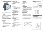
Polar PDU
Serial Communicator
User’s Manual
Version 4.0
December 2013
While every effort has been made to ensure the accuracy of all information, Subzero does not accept liability
for any errors or omissions and reserves the right to change information and descriptions of listed services and products.
support@s ubzeroe ng.com
www.subze roeng.c om
©2014 Subzero Engineering. All rights reserved.
Rev.5 01/14
Polar PDU Serial Communicator Manual
December 2013
Table of Contents
INTRODUCTION................................................................................................... 3
LEGAL INFORMATION................................................................................................ 3
WARRANTY ............................................................................................................. 3
NOMENCLATURE ...................................................................................................... 3
SOFTWARE OVERVIEW ..................................................................................... 4
INSTALLATION .................................................................................................... 5
RUNNING EPSERIAL APPLICATION: ........................... ERROR! BOOKMARK NOT DEFINED.
SELECTING A PDU .................................................................................................. 6
MONITORING A PDU ............................................................................................... 7
PDU CONFIGURATION ............................................................................................. 8
NETWORK CONFIGURATION .................................................................................... 12
BRANCHES CONFIGURATION................................................................................... 13
OUTLETS/RECEPTACLE CONFIGURATION ................................................................. 14
LOGGING CONFIGURATION ..................................................................................... 15
GROUPS CONFIGURATION ...................................................................................... 16
APPENDIX A: CONNECTING AND LINKING PDUS ........................................ 17 S u b z e ro E n g in e e rin g
2
Polar PDU Serial Communicator Manual
December 2013
INTRODUCTION
This document is the User’s Manual for Subzero Polar PDU Serial Communicator
Software.
Polar PDU Serial Communicator Software User Manual
©2015 Subzero Engineering. All rights reserved.
Legal Information
The information contained in this guide is subject to change without notice.
Subzero shall not be liable for technical or editorial errors or omissions contained herein;
nor is it liable for any injury, loss, or incidental or consequential damages resulting from
the furnishing, performance, or use of this material and equipment.
Warranty
Subzero Engineering guarantees manufactured products and each part or component
thereof against all defects in material and/or workmanship. Subzero agrees to remedy
any manufacturing defect either through replacement or repair at no charge provided
that the defective unit is returned, transportation prepaid, to the Subzero factory.
The warranty extends for a period of one year from the date of installation or initial use,
provided that this period shall not exceed 18 months from the original date of shipment
from the factory.
Any product that has been repaired or replaced shall be similarly warranted on its repair
or replacement for the remaining product warranty period or 90 days from the date of
repair or replacement, whichever expires last.
This warranty does not extend to products that have been subjected to neglect, accident
or improper use, nor to units that have been altered by non-Subzero personnel.
No warranties other than those set forth in this section are given or implied with respect
to the products furnished. Subzero shall, in no event, be liable for consequential
damages, for loss, damage or expense directly or indirectly arising from the use of the
products, for any inability to use materials or from any other cause.
Nomenclature
PDU: Polar Power Distribution Unit product
Receptacle/Outlet: Electrical output port
Primary Role: PDUs can be linked to share one network connection. The Primary Role
indicates the PDU that is attached to the network and is the beginning of a daisy chain of
up to 20 linked PDUs. There is only one Primary PDU in a daisy chain.
Secondary Role: Role assigned to a PDU that is 1) linked to the primary PDU, or 2) a
stand-alone PDU.
Alternate Role: a second PDU connected to the network to provide a backup network
connection if the Primary PDU loses power.
S u b z e ro E n g in e e rin g
3
Polar PDU Serial Communicator Manual
December 2013
SOFTWARE OVERVIEW
The Polar PDU Serial Communicator software is a Microsoft Windows based application
that can be used to configure, monitor and control a single PDU or linked PDUs via the
Serial port on the PDU.
The Polar PDU Serial Communicator is available for download on the Subzero Website.
A Serial Setup Cable (Subzero P/N 6.0.000.004, ordered separately) is required to
attach the PDU to the computer running the Polar PDU Serial Communicator software.
Polar PDU Serial Communicator Software Features:
• Access, monitor and control up to 20 linked PDUs using a single direct serial cable
connection to a computer running the epSerial software application.
• Measure and monitor voltage, current (A), power (kW), power factor and energy
(kilowatt-hours) for each branch circuit on each PDU; the sum of all power used by
PDU loads.
• Measure and monitor voltage, current (A) power (kW) and energy (kilowatt-hours) on
individual outlets on Monitored Plus and Swtiched Plus models; the sum of all power
used by specific PDU loads.
• Set alarm warning thresholds for each branch on all models; set alarm thresholds for
each outlet on Monitored Plus and Switched Plus models.
• Turn outlets on or off and cycle power remotely on Switched and Switched Plus
models; set power on and cycle delays.
• Use as bench software to complete detailed IP setup for monitoring with the built-in
web software before the PDU is attached to and monitored though a production
Ethernet network; includes setup of data and alarm logging and email notifications
via an SMTP server functions.
• Use as bench software to complete SNMP setup for monitoring with a third-party
DCIM software that accepts SNMP traps; allows designation of separate Query and
Trap Ports and assignment of separate Access Hosts and Trap Hosts IPs (three
each).
S u b z e ro E n g in e e rin g
4
Polar PDU Serial Communicator Manual
December 2013
INSTALLATION
The Polar PDU Serial Communicator software application is available on the Subzero
website and link below:
www.subzeroeng.com/PolarPDUs/Downloads
1. In the download table, under the Polar Power Distribution Units sub heading, select Polar
PDU Serial Communicator link to download the installer file.
2. Double click the PolarPDUSerialCommunicatorSetup.msi file to open the installer and
follow the instructions to install the Polar PDU Serial Communicator software.
3. The setup program will create the directory C:\Program Files (x86)\Polar PDU\Polar PDU
Serial Communicator\, install the software and place a shortcut on your desktop.
4. Before using the application, connect the serial cable (P/N 6.0.000.004, ordered
separately) to the serial port of the computer and the serial port In of the PDU. Connect
the cable to the Primary PDU when several PDUs are linked. If your computer does not
have a Serial port then use a USB-Serial Adapter (not included with serial cable, ordered
separately). See Appendix A for more details.
Running Polar PDU Serial Communicator software:
Double click the Polar PDU Serial Communicator Icon on the Desktop
When the application opens (see below, left), select the L button next to the Com Port combo
box to enter the Login Credentials (below, right). The default is admin, admin. Click OK.
S u b z e ro E n g in e e rin g
5
Polar PDU Serial Communicator Manual
December 2013
Select the appropriate COM Port and click on the Connect button (see above, left).
Serial port setting on the computer must be: 9600, 8 bit, no parity, 1 stop bit.
The main screen (below) will display.
Main screen
Selecting A PDU
Select the PDU that you wish to access from the list and click Monitor or Configure to
access that PDU.
The Primary PDU, which is attached directly to the computer with the serial cable, and
any Secondary PDUs, which are linked/daisy chained to the Primary PDU, are displayed
in a list under the Select PDU area. See Appendix A for more information on linking
PDUs.
The Primary PDU is listed first, shown as PDU Name in the example above. Note that
each PDU is assigned a different number followed by the PDU Name assigned by the
administrator. This list can be sorted by name. To display linked PDUs in the order in
which they are physically linked, use a naming convention that includes the order of the
linked PDU like those shown in the example above (Linked PDU 1, Linked PDU 2,
Linked PDU 3).
S u b z e ro E n g in e e rin g
6
Polar PDU Serial Communicator Manual
December 2013
Monitoring A PDU
To display the current, temperature, humidity and port status, click on the Monitor button.
Depending on the PDU model the appropriate info will be displayed.
• On single-phase units with two breakers, outlets are divided into two branch groups.
• On three-phase units with three breakers, outlets will be divided into three groups.
• Below is a sample of the display for a three-phase Switched Plus PDU (P/N
6.6.3.E60.19.15), with six breakers. Outlets are divided into six branch groups.
If Environmental Probes (P/N 6.0.000.001 or 6.0.000.002, sold separately) are attached
to the PDU, Temperature and Humidity will be displayed at the top of the screen.
Individual outlet (port) values are only listed on Monitored Plus and Switched Plus
models. The example above is a Switched Plus model.
From the Status screen, you can view Voltage, Current, Power (kW) and Power Factor
values. On Switched or Switched Plus PDUs, you can also turn outlets on or off (Control
check boxes) and reset/cycle power (with R buttons).
Click on the Energy button at the bottom of the Status screen to see energy
consumption in kilowatt-hours (kWh). This is the sum of power used since the last clear,
reboot or reset.
S u b z e ro E n g in e e rin g
7
Polar PDU Serial Communicator Manual
December 2013
Below is a sample of the Energy display for a three-phase Switch Plus PDU (P/N
6.6.3.E60.19.15) with six breakers. No energy use has been recorded yet.
On single-phase units with two breakers, outlets are divided into two branch groups.
On three-phase units with three breakers, outlets are divided into three branch groups.
Individual outlet (port) values are only listed on Monitored Plus and Switched Plus models.
The Clear button will reset values to zero.
Click on OK button to go back to the Main Menu.
PDU Configuration
To configure the PDU, select a PDU from the list and click on Configure button.
Configure the primary PDU first (the first PDU listed in the Select PDU list).
Network Settings are setup on the Primary PDU only.
S u b z e ro E n g in e e rin g
8
Polar PDU Serial Communicator Manual
December 2013
The Basic Configuration screen will display. Note that the Outlets and Groups buttons
under the Other Configurations area are not available on Monitored models.
Click on the Load button to get settings from the PDU.
Enter/change settings as required, or use Set Defaults to reset PDU to factory settings.
See the next page for field descriptions.
Click Save to change/update settings.
S u b z e ro E n g in e e rin g
9
Polar PDU Serial Communicator Manual
December 2013
PDU:
• PDU Name and Description are unique user assigned values for the PDU.
• PDU Name identifies the PDU in the list on the epSerial software login screen, is
listed in the upper left corner of each screen, and on the PDU’s LCD Display.
Users:
• Local User Logins, provides access to PDU using software.
• Permission is 0 to disable, 3 for viewer, 5 for control and 7 for admin.
Notifications:
• Fixed Interval: How often measurements are sent via SNMP Trap.
• Alarm Interval: Amount of time before alarm is sent via SNMP Trap after alarm
condition.
• Load difference: Amount of change in current that prompts intermediate SNMP Trap.
Display brightness:
• Controls the local display. 0-9, with 9 as brightest.
Display timeout:
• Controls the local display. How long display will stay on after use.
Login Timeout:
• Amount of idle time before software logs out and requires new login.
Link Attached PDU Count
• Number of linked PDUs attached to the Primary PDU. Used to prompt optional
Missing PDU alarm if a linked PDU stops communicating with the Primary PDU.
PDU Options:
• Input top – Flips PDU’s LCD display image 180° so that it is easy to read when the
PDU is mounted into the cabinet so that the power cord exist the top of the PDU.
• Celsius – Changes temperature measurements from Environmental Probe to
degrees Celsius. Default setting is degrees Fahrenheit.
• Enable Web – Allows access to the PDU using the Ethernet connection and a web
browser through HTTP.
• Primary PDU – Designates PDU as Primary PDU for IP consolidation. Only selected
if this PDU is linked, is the first PDU in the daisy chain and is the PDU with the
Ethernet or Serial Connection. All linked PDUs are accessed through the Primary
PDU’s IP address. There is only one Primary PDU for each group of linked PDUs.
• Alternate PDU – Designates PDU as Alternate PDU. Only selected if this PDU is
linked and will provide a backup Ethernet connection and IP address to access
linked PDUs in case the Primary PDU loses its Ethernet connection. There is only
one Alternate PDU for each group of linked PDUs. Alternate PDU is optional.
• Share Role – Only available when the Alternate PDU assumes the primary role.
Allows the Alternate PDU to keep the primary role when the Primary PDU returns to
service. All linked PDUs will be accessible through the Alternate PDU’s IP address
until share role is unchecked. If left unchecked, access to linked PDUs through the
S u b z e ro E n g in e e rin g
10
Polar PDU Serial Communicator Manual
•
•
•
•
•
December 2013
Alternate PDU’s IP address is dropped once the Primary PDU returns to service and
the user must log back into the Primary PDU to access linked PDUs.
Disable Local Auth – No login required for PDU’s LCD Display or Web access. All
users will have view permissions.
Out of Service – Stops PDU from generating alarms when the main
communications module is rebooted. Select during resets or firmware upgrades.
Missing PDU Notify – Generates an alarm if the Primary PDU loses connection with
the Alternate PDU or any Linked PDUs based on Link Attached PDU Count value.
Role Change Notify – Generates an alarm if the Alternate PDU assumes the
primary PDU role.
Show LCD Outlets – Only available for Monitored Plus (6.4.X.XXX.XX.XX) and
Switched Plus (6.6.X.XXX.XX.XX) models. Displays individual Outlet current on the
PDU’s LCD Display.
Environmental Units:
• Probe Temperature/Humidity – enter maximum and minimum values and alarm
warning thresholds in degrees Fahrenheit and percentage of relative humidity
(default). For degrees Celsius (temperature), check the Celsius box under PDU
options above.
• Probe Names – unique user defined name for each probe.
Other Configurations:
• Click buttons to access additional setup screens. Details are on the following pages.
Menu buttons:
• Clear – clears all data from data fields.
• Set Defaults – resets all data fields to factory defaults.
• Network Only – only resets all data
fields on the Network Configuration
screen.
• User Information Only – Erases all
user accounts except the default admin
account (Basic Configurations, Users).
• Other Information Only – resets all
other data fields (names, alarms, etc.)
• All Configurations – resets all of the
above.
• None/Reboot PDU – for soft reboot of
LCD screen and main communications
module. Outlets will not lose power.
•
•
•
Load – retrieves existing field values from PDU.
Save – saves all changes to field values.
Cancel – exits screen without recording any changes to field values.
S u b z e ro E n g in e e rin g
11
Polar PDU Serial Communicator Manual
December 2013
Network Configuration
From the Basic Configuration screen, click the Network button under the Other
Configurations category for the detailed Network Configuration screen. Click on Load:
You can enter detailed network configuration for IP, Services/Ports, SNMP, SMTP, Time
Synch, Radius Authentication and AD Authentication here. Polar PDUs are not SEMA
compatible at this time. Do not change SEMA settings. Click Save, or Cancel if no new
information was added or modified.
S u b z e ro E n g in e e rin g
12
Polar PDU Serial Communicator Manual
December 2013
Branches Configuration
From the Basic Configuration screen, click the Branches button under the Other
Configurations category for a detailed Branches configuration screen. Click on Load.
PDUs may have one, two, three or six branches. You can enter maximum and minimum
values and alarm warning thresholds for Voltage and Current for each branch circuit on
the PDU. Click Save, or Cancel if no new information was added or modified.
S u b z e ro E n g in e e rin g
13
Polar PDU Serial Communicator Manual
December 2013
Outlets/Receptacle Configuration
From the Basic Configuration screen, click the Outlets button under the Other
Configurations category for a detailed Outlet/Receptacle Configuration screen (note that
this screen is not available on Monitored PDUs which do not support per outlet
monitoring and control).
Use the Select Branch combo box in the top left corner to select the branch,
corresponding outlets are listed. Outlets are also numbered and color-coded on the
PDU.
Click the Load button to load values from the PDU or enter new values.
•
•
•
•
Name and Description – unique customer assigned values.
Delays – (on Switched and Switched Plus models only) set per outlet power on and
reset delays so that power is gradually restored to reduce inrush current.
On/Off – (on Switched and Switched Plus models only) turn outlet on when checked,
off when not checked. Allows unused outlets to be turned off to prevent unauthorized
use of power and unplanned loads.
Current Limits – (on Monitored Plus and Switched Plus models only) enter maximum
and minimum values and alarm warning thresholds for Current for each outlet on the
PDU.
Click Save. Note that this will overwrite any values that are currently set in the PDU.
S u b z e ro E n g in e e rin g
14
Polar PDU Serial Communicator Manual
December 2013
Logging Configuration
From the Basic Configuration screen, click the Logging button under the Other
Configurations category for a detailed data Logging Configuration screen.
Activating the logging feature will keep a local record (log) of metrics, alarms, and PDU
configuration changes. The log file is saved on the local memory of the Primary PDU.
Local memory is limited. Log files can be downloaded for archiving onto a connected
client computer or server. New files will overwrite old files as local memory is filled.
•
•
•
•
Options – Select Enable Logging Feature to turn logging on. Check the items that
you wish to log. Metrics are unit measurements (voltage, current, power, etc.).
Local Logging – Designate the interval for recording metric data. Local memory is
limited, so you can designate a warning based on percentage of use to prompt a log
download.
External Logging – When the PDU has an Ethernet connection, you can store log
files on a server that is accessible to the PDU. Checking Auto Transfer will copy a
log file to the server every six hours as long as the connection is available.
Save settings to begin logging.
S u b z e ro E n g in e e rin g
15
Polar PDU Serial Communicator Manual
December 2013
Groups Configuration
From the Basic Configuration screen, click on the Groups button under the Other
Configurations category for a detailed Group Configuration screen (note that this screen
is not available on Monitored PDUs which do not support per outlet monitoring and
control).
To view or modify an existing Group, use the Select Group combo box in the lower right
corner to select the group and click the Load button to load values from the PDU.
To create a new Group of receptacles/outlets, enter a Group name in the field at the top and
the PDU ID and outlet number for each outlet in the group. The Group can include outlets
from multiple PDUs.
•
•
PDU ID is the unique number assigned by the Polar PDU Serial Communicator software
to each PDU at login. The PDU ID for each PDU is included in the header of each menu.
For example: 0017E7 is this PDU’s ID.
Outlet number is the number assigned to the outlet on the PDU. See the Monitor page or
Outlet/Receptacle Configuration tab. Outlets are also numbered on the PDUs. If PDUs
are linked, you can create Groups that include outlets from multiple PDUs.
Click Save. Note that this will overwrite any values that are currently set in the PDU.
S u b z e ro E n g in e e rin g
16
Polar PDU Serial Communicator Manual
December 2013
APPENDIX A: CONNECTING AND LINKING PDUS
Connect the PDU directly to a computer with the Polar PDU Serial Communicator
software using the Serial Setup Cable (Subzero P/N 6.0.000.004, ordered separately).
The cable has an RJ45 connector on one end and a DB9 connector on the other end.
Attach the RJ45 connector to the Daisy Chain In Serial Port on the PDU. Attach the DB9
connector to the computer or use an USB-to-DB9 adapter if the computer does not have
a DB9 connector.
USB port
Daisy Chain Out Serial Port
Environmental
Environemtal port
port
Daisy Chain In Serial Port
Ethernet Port
Push buttons for matching Icons in the LCD
Status LED
You can link (daisy chain) up to 20 PDUs together (1 Primary and 19 Secondary) and
access all of the PDUs from a single Ethernet network or direct serial connection to the
Primary PDU.
S u b z e ro E n g in e e rin g
17
Polar PDU Serial Communicator Manual
December 2013
To link PDUs:
• Connect a standard Cat 5/6 four-pair network patch cord or network cable with RJ45
connectors from the Primary PDU’s Daisy Chain Out Serial Port to the next PDU’s
Daisy Chain In Serial Port.
•
•
•
•
•
Continue this process linking the Out Port to the In Port for additional PDUs; linking
up to 20 PDUs.
Using the setup buttons on the local display, change the Role of the primary PDU
from secondary (the default) to Primary in order to view the linked PDUs using the
Serial Software.
To access linked PDUs using a Serial Connection, attach the Serial cable (P/N
6.0.000.004, ordered separately) between the Primary PDU’s Daisy Chain In Serial
Port and the computer that has the Polar PDU Serial Communicator software
installed.
To access linked PDUs using the built in web interface, refer to the Polar PDU User
Manual available for download on www.subzeroeng.com/PolarPDUs/Downloads.
For additional assistance, contact Support:
801.810.3500 • [email protected].
S u b z e ro E n g in e e rin g
18