1
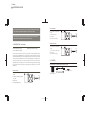
2 colors
PANTONE BLACK M
PANTONE 400 M
USER MANUAL
Tile 64 PXL Wash
Tile 64 PXL Matrix
Mirror 64PXL Wash
Please check for the latest updates and changes on the TRAXON website.
© TRAXON TECHNOLOGIES ALL RIGHTS RESERVED.
WWW.TRAXONTECHNOLOGIES.COM
HONG KONG
NEW YORK
PARIS
TOKYO
RIO DE JANEIRO
FRANKFURT
MELBOURNE
SHANGHAI
BIRMINGHAM
ROTTERDAM
Manual - Version 1.0
1 colors
PANTONE BLACK M
USER MANUAL
1. INTRODUCTION: P1
2. CONTENTS: P2
3. SAFETY AND PRECAUTIONS: P3
4. INSTALLATION AND SYSTEM CONFIGRATION: P4-9
4-1 MOUNTING: P4
4-2 DATA CONNECTION: P5-6
4-3 POWER CONNECTIONS: P7-8
4-4 CONTROL: P9
5. TROUBLESHOOTING: P10
6. CARE AND MAINTENANCE: P11
7. TECHNICAL SPECIFICATION: P11-12
8. WARRANTY STATEMENT: P12
1 colors
PANTONE BLACK M
FOR YOUR OWN SAFETY AND THAT OF THE PRODUCT, PLEASE READ THIS USER
GUIDE CAREFULLY BEFORE BEGINNING SET-UP AND INSTALLATION!
TILE 64PXL MATRIX
• 64 individually controllable RGB
500mm/19.7”
SMDs
95mm/3.75”
75mm/2.95”
• Clearly defined pixels
CAUTION: DO NOT OPEN OR HANDLE THE PANELS EXCEPT AT A STATIC FREE
• DMX Control
WORKSTATION OR WEARING AN ANTISTATIC WRIST STRAP.
• RJ45 Cat5E Data Cabling
TOP
FRONT
1. INTRODUCTION
MIRROR 64PXL WASH
(1PXL SERIES)
• 64 individually controllable RGB
TILE 64PXL WASH (PA-TI-50300)
BACK
MIRROR 64PXL WASH (PA-MI-50300)
500mm/19.7”
SMDs
TILE 64PXL MATRIX (PA-TI-50200)
95mm/3.75”
75mm/2.95”
• Premium reflective glass surface
These products are part of the Traxon ™ Panels product line, enabling a flexible setup of
medium to large scale RGB LED color changing walls. The 64PXL panels feature each 64
individually addressable pixels for full programming liberty. While the Wash versions enable
optimal video replay capabilities thanks to Traxon Light Management, the Matrix version
offers clearly defined pixels for sharp graphical effects. Traxon Mirror 64PXL Wash
additionally serves as high class black mirror when switched off. High power LED technology
combined with low power consumption brings the best solution possible for any number of
applications.
• DMX Control
TOP
• RJ45 Cat5E Data Cabling
FRONT
BACK
2. CONTENTS
TILE 64PXL WASH / TILE 64PXL MATRIX / MIRROR 64PXL WASH
1 X RJ45 Data Cable
TILE 64PXL WASH
• 64 individually controllable RGB
4 X M4 Mounting Screws (20mm)
1 x Panel
(Data & Power cables fitted)
500mm/19.7”
SMDs
1 X DC Power Cable
75mm/2.95”
95mm/3.75”
• Seamless color transition between
the pixels
TOP
• DMX Control
• RJ45 Cat5E Data Cabling
1
FRONT
BACK
2
1 colors
PANTONE BLACK M
3. SAFETY PRECAUTIONS
4. INSTALLATION AND SYSTEM CONFIGURATION
Failure to adhere to the following instructions could result in death, serious injury, or property
damage, and will void the product warranty.
4-1 MOUNTING
• Use a pencil or chalk to mark the horizontal alignment before installation.
DANGER – ENSURE THAT MAIN POWER SUPPLY IS UNPLUGGED BEFORE
• Install four screws to the wall. Horizontal and vertical clearance between the screws should be
INSTALLING OR WIRING THE PRODUCT.
340mm.
• Hang the panel on the wall as shown in Fig 1.
CAUTION – POWER/DATA SUPPLY MUST BE INSTALLED BY A QUALIFIED
FIG 1
ELECTRICIAN OR TECHNICIAN IN ACCORDANCE WITH RELEVANT LOCAL
STANDARDS AND REGULATIONS.
340mm/13.4”
DO NOT ATTEMPT TO INSTALL OR USE THE PRODUCT UNTIL YOU HAVE READ
THIS MANUAL THOROUGHLY AND UNDERSTAND THE INSTALLATION
DO NOT USE THE PRODUCT IF ANY CABLES ARE DAMAGED.
DO NOT MOUNT ON
UNEVEN SURFACE
This product is designed for indoor use only.
An ambient operating air temperature range of -15°C~+55°C (+4°F ~ +131°F) must be
adhered to at all times.
DO NOT disassemble. The product has no user serviceable parts.
min.6mm/0.24”
340mm/13.4”
INSTRUCTIONS.
WALL MOUNT
DO NOT use the product if the cover shield is broken.
If the product has been transported or stored in low temperatures, DO NOT connect it to the
power supply until it has reached room temperature, to prevent any internal condensation
from damaging the product’s electronics.
DO NOT expose the product to moisture, extreme heat or direct sunlight. Use in a clean and
dust free environment.
3
Avoid looking directly into the LED light at a close distance.
IMPORTANT NOTE
Leave at least 6mm between the screw head and the wall.
Use of the supplied wall-mount accessories is strongly recommended.
For the best visual effect, mount on an even surface.
CAUTION – DO NOT INSTALL THE PANEL IF THE COVER SHIELD IS DAMAGED.
4
1 colors
PANTONE BLACK M
4-2.1 ADDRESS SETTING
4-2 DATA CONNECTION
The 64PXL panels are controlled by Traxon Butler (LM-CS-50041), or standard DMX512
Ethernet to DMX Gateway units. Each Butler can control 2 sets of 2 panels for a total of 4
panels. (2 x 512 DMX channels)
Connect the panels to the Butler using the supplied CAT5e patch cables (Pin1: DMX-, Pin2:
DMX+, Pin3: GND) as shown in the diagram below (Fig 2).
Each Butler can control 2x2 panels of 192 DMX-channels each in a daisy-chain configuration,
i.e. maximum 4 panels. Each panel’s starting address range is set using DIP switches on the
rear of the panel. For each set of 2 panels:
• Set the first panel’s DIP1 switch to OFF (address range 1-192).
• Set the second panel’s DIP1 switch to ON (address range 193-384)
All the other DIP switches should be set to OFF.
FIG 2
ONLY QUALIFIED PERSONNEL SHOULD INSTALL THIS PRODUCT. INSTALLATIONS
ADDRESS
ADDRESS
1 2 3 4
1 2 3 4
PANEL 4
PANEL 3
1 2 3 4
1 2 3 4
ON OFF OFF OFF
ON OFF OFF OFF
ON OFF OFF OFF
ON OFF OFF OFF
PANEL 2
MUST COMPLY WITH LOCAL REGULATIONS.
ADDRESS
ADDRESS
PANEL 1
ENSURE THAT THE POWER SUPPLY IS OFF BEFORE CONNECTING OR
DISCONNECTING PANELS.
IMPORTANT NOTE
Length of the data cable between the Butler and the last panel should not exceed
100m/330ft.
Data Cable from DMX out
to DMX IN on next panel
Data Cable from DMX out
to DMX IN on next panel
DMX
OUT IN
NOTE:
Data cable max. length:
100m/330ft from DMX controller
to the last fixture, using CAT5E cable
DMX Data Cable 1
DMX Data Cable 2
DMX OUT
DATA CONNECTION:
BUTLER LM-CS-50041
Each butler can connect max. 4 panels (2x2 pcs)
In this configuration, the Butler draws power directly from the 64PXL panels and does not
require any external power supply.
5
6
1 colors
PANTONE BLACK M
4-3 POWER CONNECTIONS
• Connect the AC power cable (100~240VAC) to the first 3 terminals (L,N, ) .
Connect the 64PXL panels to an external 24V power supply as shown in the connection diagram
• Make sure the panels are properly positioned and securely installed before use.
below (Fig 3).
IMPORTANT NOTE
• The length of each DC power cable should not exceed 15m/49.5ft (18 AWG wire).
FIG 3
• To prevent overheating and overloading: do not tamper with the dc power cable.
• Make sure that only one panel is connected to each dc power cable.
CONNECTOR BLOCK 2P
BLACK WIRE 18 AWG (-V)
BLACK WIRE WITH
WHITE HIDDEN LINE
18 AWG (+V)
THE CONNECTION OF THE POWER SUPPLY SHOULD ONLY BE HANDLED BY
AC-PS-00009
POWER SUPPLY
QUALIFIED TECHNICIAN.
Max. 4 panels per power supply
THE MANUFACTURER BEARS NO RESPONSIBILITY FOR ANY MALFUNCTION OR
SPADE TERMINAL
+V
-V
N
L
DAMAGE CAUSED BY IMPROPER ELECTRICAL INSTALLATIONS.
DC POWER CABLE
NEUTRAL
OR DISCONNECTING PANELS.
LIVE
GROUND
ENSURE THAT THE POWER SUPPLY IS SWTICHED OFF BEFORE CONNECTING
PLASTIC COVER
DC POWER CABLE TO 1st FIXTURE (Max. 15m/49.5ft)
DC POWER CABLE TO 2nd FIXTURE
DC POWER CABLE TO 3rd FIXTURE
DC POWER CABLE TO 4th FIXTURE
AC POWER CABLE
100~240VAC
To power input of panel
Each 24V System Power Supply (320W) (AC-PS-00009) can power up to 4 panels.
Make sure the panels are properly positioned and securely installed before connecting the
power.
• Connect the DC OUT of the 24V System Power Supply to the POWER INPUT located at the
back of each panel using a DC power cable. Connect the black wire 18AWG to -V and the
black wire with white line 18AWG to +V.
• Connect the DC power cables for the 3rd and 4th panels to the same terminals on the power
7
supply, as shown above.
8
1 colors
PANTONE BLACK M
4-4 CONTROL
5. TROUBLESHOOTING
For configuration of the individual pixels per set of 2 panels, please refer to the standard DMX
chart below (Fig 4).
Please note that you can modify the DMX channel allocation to suit your specific project using
Traxon Light Management software. Please refer to the Butler (LM-CS-50041) user manual for
configuration details.
Problem
Solution
Panels cannot be installed
Ensure the installation surface is flat and smooth
close together
Duplicated images appear
• Both panels have been set to the same starting address.
• Check each panel’s DIP switch setting.
FIG 4
DMX ADDRESSING - RGB CHANNELS
Images do not show on the
• Data cable length exceeds 100m/330ft.
connected panels
• Check the connections of the Butler and panels.
• Check that the power supply is connected to the panels
9
Frist Panel
(Second Panel)
1-3
(193-195)
25-27
(217-219)
49-51
(241-243)
73-75
(265-267)
97-99
(289-291)
121-123
(313-315)
145-147
(337-339)
169-171
(361-363)
Frist Panel
(Second Panel)
4-6
(196-198)
28-30
(220-222)
52-54
(244-246)
76-78
(268-270)
100-102
(292-294)
124-126
(316-318)
148-150
(340-342)
172-174
(364-366)
Frist Panel
(Second Panel)
7-9
(199-201)
31-33
(223-225)
55-57
(247-249)
79-81
(271-273)
103-105
(295-297)
127-129
(319-321)
151-153
(343-345)
175-177
(367-369)
Frist Panel
(Second Panel)
10-12
(202-204)
34-36
(226-228)
58-60
(250-252)
82-84
(274-276)
106-108
(298-300)
130-132
(322-324)
154-156
(346-348)
178-180
(370-372)
Frist Panel
(Second Panel)
13-15
(205-207)
37-39
(229-231)
61-63
(253-255)
85-87
(277-279)
109-111
(301-303)
133-135
(325-327)
157-159
(349-351)
181-183
(373-375)
Frist Panel
(Second Panel)
16-18
(208-210)
40-42
(232-234)
64-66
(256-258)
88-90
(280-282)
112-114
(304-306)
136-138
(328-330)
160-162
(352-354)
184-186
(376-378)
Frist Panel
(Second Panel)
19-21
(211-213)
43-45
(235-237)
67-69
(259-261)
91-93
(283-285)
115-117
(307-309)
139-141
(331-333)
163-165
(355-357)
187-189
(379-381)
Frist Panel
(Second Panel)
22-24
(214-216)
46-48
(238-240)
70-72
(262-264)
94-96
(286-288)
118-120
(310-312)
142-144
(334-336)
166-168
(358-360)
190-192
(382-384)
and the power is ON.
• Check the Butler/DMX controller configuration.
No power supply
• DC power cable length exceeds 15m/49.5ft
• Wrong connection to power supply (refer to page 7)
10
1 colors
PANTONE BLACK M
6. CARE AND MAINTENANCE
Traxon™ products are of superior design and quality and should be treated with
care. The recommendations below will help fulfill and warranty obligations and gain
good use and longevity from the products.
- Make sure that the product(s) is installed correctly and securely
- For indoor use only
- Keep product in a dry and precipitation free area as this with damage the product(s)
electronics
- Keep product(s) in a dirt and dust free environment
- Keep product(s) in an extreme heat free area and ensure that it has sufficient airflow and cool
air circulation if required
- Do not attempt to service or repair the product(s) unless done by an authorized service again.
Contact the local Traxon™ office or distributor for details
- Do not drop, knock or shake the product(s) as rough handling may damage the electronics and
void the warranty
- Do not use harsh chemicals, cleaning solvents or strong detergents to clean, wipe with a damp
cloth on housings and a dry cloth on electronics to remove and buildup of dirt or dust
TILE 64 PXL MATRIX
Color resolution : 3 x 14 Bit (RGB)
Color range: 16.7 million additive RGB colors with variable intensity
Light source: Ultra Bright SMD LED
Source life: 50,000 hours under normal operating conditions
Beam angle: 120°
Power input: 24VDC
Current consumption: 35A maximum
Power consumption: 32.4W maximum
Operating temperature range: -15°C – 55°C (4°F – 131°F)
Storage temperature range: -40°C – 70°C (40°F – 158°F)
8. WARRANTY STATEMENT
Traxon warrants its Products against material or workmanship defects for a period of one (1)
year from the date of purchase provided that the purchased items are under conditions stated in
respective instruction manuals. Proof of purchase is necessary upon on warranty claim.
Any implied warranty of merchantability, or fitness for a particular purpose or use, shall be limited
to the duration of the foregoing written warranty. Otherwise, the foregoing warranty is the
If the product is not working correctly, please contact your nearest authorized service centre or
purchaser’s sole and exclusive remedy and is in lieu of all other warranties, express or implied.
Traxon Technologies office for assistance
Traxon shall not be liable for any incidental or consequential damages or a loss of anticipated 16
7. TECHNICAL SPECIFICATIONS
All warranty information, product features and specifications are subject to change without
notice.
TILE 64 PXL WASH /MIRROR 64PXL WASH
11
Color resolution : 3 x 14 Bit (RGB)
Color range: 16.7 million additive RGB colors with variable intensity
Light source: Ultra Bright SMD LED
Source life: 50,000 hours under normal operating conditions
Beam angle: 120°
Power input: 24VDC
Current consumption: 3A maximum
Power consumption: 72W maximum
Operating temperature range: -15°C – 55°C (4°F – 131°F)
Storage temperature range: -40°C – 70°C (40°F – 158°F)
12