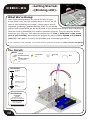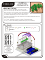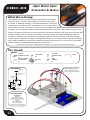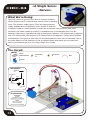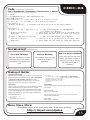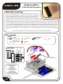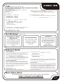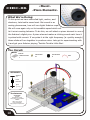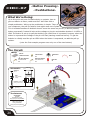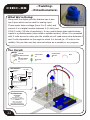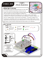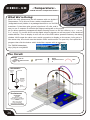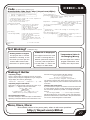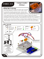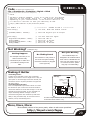
1
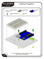
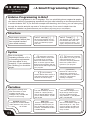
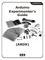
(ARDX)
arduino experimentation kit
Arduino
Experimenter’s
Guide
(ARDX)
A Few Words
About this Kit
The overall goal of this kit is fun. Beyond this, the aim is to get
you comfortable using a wide range of electronic components
through small, simple and easy circuits. The focus is to get
each circuit working then giving you the tools to figure out why.
If you encounter any problems, want to ask a question, or would
like to know more about any part, extra help is only an e-mail away [email protected].
About Open Source Hardware
All of .:oomlout:.'s projects are open source. What does this mean? It means everything
involved in making this kit, be it this guide, 3D models, or code is available for free download.
But it goes further, you're also free to reproduce and modify any of this material, then distribute
it for yourself. The catch? Quite simple; it is released under a Creative Commons (By - Share
Alike) license. This means you must credit .:oomlout:. in your design and share your
developments in a similar manner. Why? We grew up learning and playing with open source
software and the experience was good fun, we think it would be lovely if a similar experience
was possible with physical things.
(more details on the Creative Commons CC (By - Share Alike) License can be found at )
( http://tinyurl.com/2dkzmd )
About .: oomlout :.
We’re a plucky little design company focusing on producing
“delightfully fun open source products”
To check out what we are up to
http://www.oomlout.com
About Problems
We strive to deliver the highest level of quality in each and every thing we produce. If you ever
find an ambiguous instruction, a missing piece, or would just like to ask a question, we’ll try our
best to help out. You can reach us at:
[email protected]
(we like hearing about problems it helps us improve future versions)
Thanks For Choosing .:oomlout:.
.: Where to Find Everything :.
TBCN
table of contents
Before We Start
{ASEM}
Assembling the Pieces
02
{INST}
Installing the Software
03
{PROG}
A Small Programming Primer
04
{ELEC}
A Small Electronics Primer
06
The Circuits
{CIRC01} Getting Started - (Blinking LED)
08
{CIRC02} 8 LED Fun - (Multiple LEDs)
10
{CIRC03} Spin Motor Spin - (Transistor and Motor)
12
{CIRC04} A Single Servo - (Servos)
14
{CIRC05} 8 More LEDs - (74HC595 Shift Register)
16
{CIRC06} Music - (Piezo Elements)
18
{CIRC07} Button Pressing - (Pushbuttons)
20
{CIRC08} Twisting - (Potentiometers)
22
{CIRC09} Light - (Photo Resistors)
24
{CIRC10} Temperature - (TMP36 Temperature Sensor)
26
{CIRC11} Larger Loads - (Relays)
28
01
01 ASEM
assembling the
pieces
02
.: Putting It Together :.
Arduino Holder
x1
Breadboard
x1
3mm x 10mm bolt
x2
3mm nut
x4
.: For an introduction to what an Arduino is visit :.
.: http://tinyurl.com/9txjmh :.
Arduino
x1
.: Installing the IDE :.
02 INST
installing
This is the program used to write programs for the Arduino (meta?).
It may seem a little daunting at first but once you have it installed
and start playing around, its secrets will reveal themselves
(software and hardware)
Step 1: Download the software
Goto
http://arduino.cc/en/Main/Software
And download the software for your operating system
Windows XP
Step 2: Unzip the Software
Unzip
arduino-00rr-win.zip
(rr- version #)
Mac OSX
Step 2: Unzip the Software
Unzip (double click)
arduino-00rr-mac.zip (rr- version #)
Recommended Path
Move Folder
c:\Program Files\
move
Step 3: Shortcut Icon
Open
c:\program files\arduino-00rr\
(rr- version #)
Right Click
Arduino.exe
(send to>Desktop (create shortcut) )
Step 4: Plug In Your Arduino
Plug your Arduino in:
using the included USB cable, plug your Arduino board into a
free USB port
Wait for a box to pop up
/arduino-00rr/ to //Applications/
Step 3: Alias Icons
Open
//Applications/arduino-00rr/
(rr- version #)
Command Click
Make Alias
Drag to Desktop
Step 4: Install Drivers
Goto
//Applications/Arduino-00rr/drivers/
Double Click & Install
FTDIUSBSerialDriver_V2_2_9_Intel.dmg
(V2_1_9.dmg if not an Intel Mac)
Restart
Step 5: Add new Hardware
Skip searching the internet
Step 5: Plug In Your Arduino
(click the next box when prompted to do so)
Plug your Arduino in:
Install from a Specific destination
using the included USB cable, plug your Arduino board into a
free USB port
(click “Install from a list or specific location (Advanced))
Choose the Location
c:\program files\arduino-00rr\drivers\FTDI USB Drivers\
Finished
.: NOTE: :.
.: Encountering problems? :.
.: Would like more details? Using Linux? :.
.:http://tinyurl.com/r99d8u :.
03
03 PROG
programming
primer
.: A Small Programming Primer:.
Arduino Programming in Brief
The Arduino is programmed in the C language. This is a quick little primer targeted at people
who have a little bit of programing experience and just need a briefing on the ideosyncrocies of
C and the Arduino IDE. If you find the concepts a bit daunting, don't worry, you can start going
through the circuits and pick up most of it along the way. For a more in depth intro the
Arduino.cc website is a great resource (the foundations page http://tinyurl.com/954pun)
Structure
Each Arduino program
(often called a sketch) has
two required functions
(also called routines).
void setup(){
}
void loop(){
}
All the code between the two
curly brackets will be run once
when your Arduino program
first runs.
This function is run after setup
has finished. After it has run
once it will be run again, and
again, until power is removed.
// (single line comment)
It is often useful to write notes
to yourself as you go along
about what each line of code
does. To do this type two back
slashes and everything until the
end of the line will be ignored by
your program.
/* */(multi line comment)
If you have a lot to say you can
span several lines as a
comment. Everything between
these two symbols will be
ignored in your program.
Syntax
One of the slightly
frustrating elements of C is
its formating requirements
(this also makes it very
powerful). If you remember
the following you should be
alright.
{ } (curly brackets)
Used to define when a block of
code starts and ends (used in
functions as well as loops)
; (semicolon)
Each line of code must be
ended with a semicolon (a
missing semicolon is often the
reason for a programme
refusing to compile)
A program is nothing more
than instructions to move
numbers around in an
intelligent way. Variables are
used to do the moving
int (integer)
The main workhorse, stores a
number in 2 bytes (16 bits).
Has no decimal places and will
store a value between -32,768
and 32,768.
long (long)
Used when an integer is not
large enough. Takes 4 bytes
(32 bits) of RAM and has a
range between -2,147,483,648
and 2,147,483,648.
boolean (boolean)
A simple True or False variable.
Useful because it only uses one
bit of RAM.
float (float)
Used for floating point math
(decimals). Takes 4 bytes (32
bits) of RAM and has a range
between -3.4028235E+38 and
3.4028235E+38.
char (character)
Stores one character using the
ASCII code (ie 'A' = 65). Uses
one byte (8 bits) of RAM. The
Arduino handles strings as an
array of char’s
Variables
04
.:For a full programming reference visit:.
http://tinyurl.com/882oxm
03 PROG
programming
primer
Maths Operators
Operators used for
manipulating numbers.
(they work like simple
maths)
=
(assignment) makes something equal to something else (eg. x =
10 * 2 (x now equals 20))
% (modulo) gives the remainder when one number is divided by
another (ex. 12 % 10 (gives 2))
+ (addition)
- (subtraction)
* (multiplication)
/ (division)
Comparison Operators
Operators used for logical
comparison
==
!=
<
>
(equal to) (eg. 12 == 10 is FALSE or 12 == 12 is TRUE)
(not equal to) (eg. 12 != 10 is TRUE or 12 != 12 is FALSE)
(less than) (eg. 12 < 10 is FALSE or 12 < 12 is FALSE or 12 < 14 is TRUE)
(greater than) (eg. 12 > 10 is TRUE or 12 > 12 is FALSE or 12 > 14 is
FALSE)
Control Structure
Programs are reliant on
controlling what runs
next, here are the basic
control elements (there
are many more online)
if(condition){ }
else if( condition ){ }
else { }
This will execute the code between
the curly brackets if the condition is
true, and if not it will test the else
if condition if that is also false the
else code will execute.
for(int i = 0; i <
#repeats; i++){
}
Used when you would like to
repeat a chunk of code a number
of times (can count up i++ or
down i-- or use any variable)
Digital
pinMode(pin, mode);
Used to set a pins mode, pin is
the pin number you would like
to address (0-19 (analog 0-5
are 14-19). the mode can either
be INPUT or OUTPUT.
digitalWrite(pin, value);
int digitalRead(pin);
Once a pin is set as an OUTPUT,
it can be set either HIGH (pulled
to +5 volts) or LOW (pulled to
ground).
Once a pin is set as an INPUT
you can use this to return
whether it is HIGH (pulled to
+5 volts) or LOW (pulled to
ground).
int analogWrite(pin,
value);
int analogRead(pin);
Analog
The Arduino is a digital
machine but it has the ability to
operate in the analog realm
(through tricks). Here's how to
deal with things that aren't
digital.
Some of the Arduino's pins support
pulse width modulation (3, 5, 6, 9, 10,
11). This turns the pin on and off very
quickly making it act like an analog
output. The value is any number
between 0 (0% duty cycle ~0v) and 255
(100% duty cycle ~5 volts).
When the analog input pins are set
to input you can read their voltage.
A value between 0 (for 0
volts) and 1024 (for 5
volts) will be
returned
05
04 ELEC
electronics
primer
.: A Small Electronics Primer:.
Electronics in Brief
No previous electronic experience is required to have fun with this kit. Here are a few details
about each component to make identifying, and perhaps understanding them, a bit easier. If at
any point you are worried about how a component is used or why its not working the internet
offers a treasure trove of advice, or we can be contacted at [email protected]
Component Details
LED
(Light Emitting Diode)
Diode
Resistors
Transistor
Hobby Servo
DC Motor
06
What it Does:
Emits light when a small current is passed
through it. (only in one direction)
Identifying:
Looks like a mini light bulb.
No. of Leads:
2 (one longer this one connects to positive)
Things to watch out for:
- Will only work in one direction
- Requires a current limiting resistor
More Details on Wikipedia:
http://tinyurl.com/zhpyv
What it Does:
The electronic equivalent of a one way
valve. Allowing current to flow in one
direction but not the other.
Identifying:
Usually a cylinder with wires extending from
either end. (and an off center line indicating polarity)
No. of Leads:
2
Things to watch out for:
- Will only work in one direction
(current will
flow if end with the line is connected to ground)
More Details on Wikipedia:
http://tinyurl.com/ysz57b
What it Does:
Restricts the amount of current that can flow
through a circuit.
Identifying:
Cylinder with wires extending from either
end. The resistance value is displayed using
a color coding system (for details see next
page)
No. of Leads:
2
Things to watch out for:
- Easy to grab the wrong value
What it Does:
Uses a small current to switch or amplify a
much larger current.
Identifying:
Comes in many different packages but you
can read the part number off the package.
No. of Leads:
3 (Base, Collector, Emitter)
Things to watch out for:
- Plugging in the right way round.(also a
(double check
the colors before using)
More Details on Wikipedia:
http://tinyurl.com/cmeqw5
current limiting resistor is often needed on the base pin)
(2N222A in this kit and find a datasheet online)
More Details on Wikipedia:
http://tinyurl.com/eazkn
What it Does:
Takes a timed pulse and converts it into an
angular position of the output shaft.
Identifying:
A plastic box with 3 wires coming out one
side and a shaft with a plastic horn out the
top.
No. of Leads:
3
Things to watch out for:
- The plug is not polarized so make sure it
is plugged in the right way.
More Details:
http://tinyurl.com/4zo4he
What it Does:
Spins when a current is passed through it.
Identifying:
This one is easy, it looks like a motor. Usually
a cylinder with a shaft coming out of one
end
No. of Leads:
2
Things to watch out for:
- Using a transistor or relay that is rated for
the size of motor you're using.
More Details on Wikipedia:
http://tinyurl.com/d826yh
04 ELEC
electronics
primer
Component Details (cont.)
Piezo Element
What it Does:
A pulse of current will cause it to click a
stream of pulses will cause it to emit a tone.
Identifying:
In this kit it comes in a little black barrel, but
sometimes they are just a gold disc.
No. of Leads:
2
Things to watch out for:
- Difficult to misuse.
More Details:
http://tinyurl.com/38crmu
IC (Integrated Circuit)
What it Does:
Packages any range of complicated
electronics inside, an easy to use form factor
Identifying:
The part ID is written on the outside of the
package. (this sometimes requires a lot of
light or a magnifying glass to read)
Pushbutton
What it Does:
Completes a circuit when it is pressed
Identifying:
A little square with leads out the bottom and
a button on the top.
Potentiometer
What it Does:
Produces a variable resistance dependant on
the angular position of the shaft.
Identifying:
They can be packaged in many different
form factors, look for a dial to identify.
Photo Resistor
What it Does:
Produces a variable resistance dependant on
the amount of incident light.
Identifying:
Usually a little disk with a clear top and a
curvy line underneath.
Resistor Color Code
Examples:
green-blue-brown - 560 ohms
red-red-red - 2 200 ohms (2.2k)
brown-black-orange - 10 000 ohms (10k)
0
1
2
3
4
-
Black
Brown
Red
Orange
Yellow
5
6
7
8
9
-
Green
Blue
Purple
Grey
White
first digit
second digit
# of zeros
tolerance
20% - none
10% - silver
5% - gold
No. of Leads:
2 - 100s (in this kit there is one with 3 (TMP36) and
one with 16 (74HC595)
Things to watch out for:
- Proper orientation.(look for marks showing pin 1)
More Details:
http://tinyurl.com/87k4d
No. of Leads:
4
Things to watch out for:
- these are almost square so can be
inserted 90 degrees off angle.
More Details:
http://tinyurl.com/cmts7d
No. of Leads:
3
Things to watch out for:
- Accidentally buying logarithmic scale.
More Details:
http://tinyurl.com/28pbhd
No. of Leads:
2
Things to watch out for:
- Remember it needs to be in a voltage
divider before it provides a useful input.
More Details:
http://tinyurl.com/c2wdkw
Lead Clipping
Some components in this kit come with very long wire
leads. To make them more compatible with a breadboard
a couple of changes are required.
LEDs:
Clip the leads so the long lead is ~7mm long and the
short one is ~5mm
Resistors:
Bend the leads down so they are 90 degrees to the
cylinder. Then snip them so they are ~6mm long.
Other Components:
Other components may need clipping
use your discretion when doing so.
07
CIRC-01
.:Getting Started:.
.:(Blinking LED):.
What We’re Doing:
LED’s (light emitting diodes) are used in all sorts of clever
things which is why we have included them in this kit. We will
start off with something very simple, turning one on and off,
repeatedly, producing a pleasant blinking effect. To get started
grab the parts listed below, pin the layout sheet to your breadboard and then plug everything in.
Once the circuit is assembled you'll need to upload the program. To do this plug the Arduino
board into your USB port. Then select the proper port in Tools > Serial Port > (the comm
port of your Arduino). Next upload the program by going to File > Upload to I/O Board
(ctrl+U). Finally bask in the glory and possibility that controlling lights offers.
If you are having trouble uploading, a full trouble shooting guide can be found here: http://tinyurl.com/89s2po
The Circuit:
Parts:
CIRC-01
Breadboard sheet
x1
560 Ohm Resistor
Green-Blue-Brown
x1
Schematic:
Arduino
pin 13
LED
(light emitting diode)
resistor (560ohm)
(blue-green-brown)
gnd
(ground) (-)
The Internet
.:download:.
printable
breadboard overlay
http://tinyurl.com/qukhvc
.
.:view:.
video of the circuit
being assembled
http://tinyurl.com/cwhx27
08
2 Pin Header
10mm LED
x4
x1
Wire
CIRC-01
Code (no need to type everything in just)
File > Sketchbook > Examples > Digital > Blink
(example from the great arduino.cc site check it out for other ideas)
/*
* Blink
*
* The basic Arduino example. Turns an LED on for one second,
* then off for one second, and so on... We use pin 13 because,
* depending on your Arduino board, it has either a built-in LED
* or a built-in resistor so that you need only an LED.
*
* http://www.arduino.cc/en/Tutorial/Blink
*/
int ledPin = 13;
// LED connected to digital pin 13
void setup()
{
pinMode(ledPin, OUTPUT);
}
// run once, when the sketch starts
void loop()
{
digitalWrite(ledPin, HIGH);
delay(1000);
digitalWrite(ledPin, LOW);
delay(1000);
// run over and over again
// sets the digital pin as output
//
//
//
//
sets the LED on
waits for a second
sets the LED off
waits for a second
Not Working? (3 things to try)
LED Not Lighting Up?
Program Not Uploading
LEDs will only work in one
This happens sometimes,
Still No Success?
direction.
try taking it out and twisting it
the most likely cause is a
A broken circuit is no fun, send
confused serial port, you
us an e-mail and we will get
180 degrees.
(no need to worry, installing it
backwards does no permanent
harm)
can change this in
back to you as soon as we can.
tools>serial port>
[email protected]
Making it Better
Changing the pin:
The LED is connected to pin 13 but we can use any of
Control the Brightness:
Along with digital (on/off) control the Arduino can control
the Arduino’s pins. To change it take the wire plugged
some pins in an analog (brightness) fashion. (more details on
into pin 13 and move it to a pin of your choice (from 0-
this in later circuits). To play around with it.
13) (you can also use analog 0-5 analog 0 is 14...)
Change the LED to pin 9: (also change the wire)
ledPin = 13; -> int ledPin = 9;
Then in the code change the line:
int ledPin = 13; -> int ledPin = (newpin);
Then upload the sketch: (ctrl-u)
Replace the loop() code with:
analogWrite(ledPin, (new number));
Change the Blink Time:
Unhappy with one second on one second off?
(new number) = any number between 0 and 255.
0 = off, 255 = on, in between = different brightness
In the code change the lines:
digitalWrite(ledPin, HIGH);
delay(time on); //(seconds * 1000)
digitalWrite(ledPin, LOW);
delay(time off); //(seconds * 1000)
Fading:
We will use another included example program. To open go to.
File > Sketchbook > Examples > Analog > Fade
Then upload to your board and watch as the LED fades in and
then out.
More, More, More:
More details, where to buy more parts, where to ask more questions.
http://tinyurl.com/cmn5nh
09
CIRC-02
.:8 LED Fun:.
.:Multiple LED’s:.
What We’re Doing:
We have caused one LED to blink, now its time to up the
stakes. Lets connect eight. We'll also have an opportunity to
stretch the Arduino a bit by creating various lighting sequences.
This circuit is also a nice setup to experiment with writing your
own programs and getting a feel for how the Arduino works.
Along with controlling the LEDs we start looking into a few simple programming methods to
keep your programs small.
for() loops - used when you want to run a piece of code several times.
arrays[] - used to make managing variables easier (its a group of variables)
The Circuit:
Parts:
CIRC-02
Breadboard sheet
x1
560 Ohm Resistor
Green-Blue-Brown
x8
Schematic:
Arduino
Arduino
Arduino
Arduino
pin 2
pin 3
pin 4
pin 5
LED
(light emitting diode)
resistor (560ohm)
(blue-green-brown)
gnd
(ground) (-)
Arduino
Arduino
Arduino
Arduino
pin 6
pin 7
pin 8
pin 9
LED
(light emitting diode)
resistor (560ohm)
(blue-green-brown)
gnd
(ground) (-)
The Internet
.:download:.
printable
breadboard overlay
http://tinyurl.com/d4gmov
.
.:view:.
video of the circuit
being assembled
http://tinyurl.com/coafoh
10
2 Pin Header
5mm GreenLED
x4
x8
Wire
CIRC-02
Code (no need to type everything in just)
Download the Code from ( http://tinyurl.com/dkpxbn )
(and then copy the text and paste it into an empty Arduino Sketch)
//LED Pin Variables
int ledPins[] = {2,3,4,5,6,7,8,9};
//An array to hold the
//pin each LED is connected to
//i.e. LED #0 is connected to pin 2
void setup()
{
for(int i = 0; i < 8; i++){
//this is a loop and will repeat eight times
pinMode(ledPins[i],OUTPUT);
//we use this to set LED pins to output
}
}
void loop()
// run over and over again
{
oneAfterAnotherNoLoop();
//this will turn on each LED one by
//one then turn each oneoff
//oneAfterAnotherLoop();
//this does the same as onAfterAnotherNoLoop
//but with much less typing
//oneOnAtATime();
//inAndOut();
}
* will then turn them off
void oneAfterAnotherNoLoop(){
int delayTime = 100;
//the time (in milliseconds) to pause
//between LEDs
digitalWrite(ledPins[0], HIGH); //Turns on LED #0
//(connected to pin 2)
delay(delayTime);
//waits delayTime milliseconds
...
...
digitalWrite(ledPins[7], HIGH); //Turns on LED #7
//(connected to pin 9)
delay(delayTime);
//waits delayTime milliseconds
//Turns Each LED Off
digitalWrite(ledPins[7], LOW); //Turns off LED #7
delay(delayTime);
//waits delayTime milliseconds
...
-----more code in the downloadable version------
/*
* oneAfterAnotherNoLoop() - Will light one then
* delay for delayTime then light the next LED it
Not Working? (3 things to try)
Starting Afresh
Some LEDs Fail to Light
Operating out of sequence
It is easy to insert an LED
With eight wires it's easy to cross
misplace a wire without
Its easy to accidentally
backwards. Check the LEDs
a couple. Double check that the
noticing. Pulling everything out
that aren't working and ensure
first LED is plugged into pin 2 and
and starting with a fresh slate
they the right way around.
each pin there after.
is often easier than trying to
track down the problem.
Making it Better
Switching to Loops:
in the loop() function there are 4 lines. The last
three all start with a '//' this means the line is
Extra Animations:
Tired of this animation? Then try the other two
treated as a comment (not run). To switch the
sample animations. Uncomment their lines and
program to use loops change the void loop()
code to:
upload the program to your board and enjoy the new
//oneAfterAnotherNoLoop();
oneAfterAnotherLoop();
//oneOnAtATime();
//inAndOut();
Upload the program, and notice that nothing has
changed. You can take a look at the two
functions, each does the same thing, but use
different approaches (hint the second one uses a
for loop)
light animations.
(delete the slashes in front of row 3 and then 4)
Testing out your own Animations:
Jump into the included code and start changing
things. The main point is to turn an LED on use
digitalWrite(pinNumber, HIGH); then to turn
it off use digitalWrite(pinNumber, LOW); .
Type away, regardless of what you change you won't
break anything.
More, More, More:
More details, where to buy more parts, where to ask more questions.
http://tinyurl.com/d2hrud
11
CIRC-03
.:Spin Motor Spin:.
.:Transistor & Motor:.
What We’re Doing:
The Arduino's pins are great for directly controlling small electric
items like LEDs. However, when dealing with larger items (like a
toy motor or washing machine), an external transistor is required.
A transistor is incredibly useful. It switches a lot of current using a
much smaller current. A transistor has 3 pins. For a negative type (NPN)
transistor you connect your load to collector and the emitter to ground. Then when a small current
flows from base to the emitter a current will flow through the transistor and your motor will spin (this
happens when we set our Arduino pin HIGH). There are literally thousands of different types of
transistors, allowing every situation to be perfectly matched. We have chosen a 2N222A a rather
common general purpose transistor. The important factors in our case are that its maximum voltage
(40 v) and its maximum current (600 milliamp) are both high enough for our toy motor (full details
can be found on its datasheet http://tinyurl.com/o2cm93 )
(The 1N4001 diode is acting as a flyback diode for details on why its there visit: http://tinyurl.com/b559mx)
The Circuit:
Parts:
CIRC-03
Breadboard sheet
x1
2.2k Ohm Resistor
Red-Red-Red
x1
Schematic:
Arduino
pin 9
resistor (2.2kohm)
(red-red-red)
Transistor
2N2222A Base
Collector
Emitter
Diode
(flyback)
Toy
Motor
gnd
(ground) (-)
+5 volts
The Internet
.:download:.
printable
breadboard overlay
http://tinyurl.com/d6jv63
.
.:view:.
video of the circuit
being assembled
http://tinyurl.com/djapjg
12
Transistor
2 Pin Header
x4
Toy Motor
x1
2N2222A (TO92)
Wire
x1
Diode
(1N4001)
x1
the transistor will have
2N222A printed on it
(some variations will have
the pin assignment reversed)
CIRC-03
Code (no need to type everything in just)
Download the Code from ( http://tinyurl.com/dagyrb )
(then simply copy the text and paste it into an empty Arduino Sketch)
int motorPin = 9; //pin the motor is connected to
void setup() //runs once
{
pinMode(motorPin, OUTPUT);
}
void loop()
// run over and over again
{
motorOnThenOff();
//motorOnThenOffWithSpeed();
//motorAcceleration();
}
/*
* motorOnThenOff() - turns motor on then off
* (notice this code is identical to the code we
used for
* the blinking LED)
*/
void motorOnThenOff(){
int onTime = 2500; //on time
int offTime = 1000; //off time
digitalWrite(motorPin, HIGH);
// turns the motor On
delay(onTime); // waits for onTime milliseconds
digitalWrite(motorPin, LOW);
// turns the motor Off
delay(offTime);// waits for offTime milliseconds
}
void motorOnThenOffWithSpeed(){
int onSpeed = 200;// a number between
//0 (stopped) and 255
int onTime = 2500;
int offSpeed = 50;// a number between
//0 (stopped) and 255
int offTime = 1000;
analogWrite(motorPin, onSpeed);
// turns the motor On
delay(onTime);
// waits for onTime
analogWrite(motorPin, offSpeed);
// turns the motor Off
delay(offTime);
// waits for offTime
}
(full speed)
(full speed)
milliseconds
milliseconds
void motorAcceleration(){
int delayTime = 50; //time between each speed step
for(int i = 0; i < 256; i++){
//goes through each speed from 0 to 255
analogWrite(motorPin, i);
//sets the new speed
delay(delayTime);// waits for delayTime milliseconds
}
for(int i = 255; i >= 0; i--){
//goes through each speed from 255 to 0
analogWrite(motorPin, i);
//sets the new speed
delay(delayTime);//waits for delayTime milliseconds
}
}
Not Working? (3 things to try)
Motor Not Spinning?
Transistor Getting Hot
Still Not Working?
Different manufacturers
The transistor will get warm, in
Sometimes the Arduino board
produce the same transistor
most cases this is okay, if you
will disconnect from the
with different pin assignments.
are worried about the
computer. Try un-plugging and
Try turning the transistor 180
temperature turn the circuit off
then re-plugging it into your
degrees.
for a bit and let it cool down.
USB port.
Making it Better
feature to control the speed of our motor. The arduino
In the loop() section change it to this
// motorOnThenOff();
motorOnThenOffWithSpeed();
//motorAcceleration();
Then upload the programme. You can change the speeds by
does this using something called Pulse Width
changing the variables onSpeed and offSpeed
Controlling Speed:
We played with the Arduino's ability to control the
brightness of an LED earlier now we will use the same
Modulation (PWM). This relies on the Arduino's ability to
operate really really fast. Rather than directly controlling
the voltage coming from the pin the Arduino will switch
the pin on and off very quickly. In the computer world
this is going from 0 to 5 volts many times a second, but
Accelerating and decelerating:
Why stop at two speeds, why not accelerate and decelerate
the motor. To do this simply change the loop() code to read
// motorOnThenOff();
// motorOnThenOffWithSpeed();
motorAcceleration();
in the human world we see it as a voltage. For example
if the Arduino is PWM'ing at 50% we see the light
Then upload the program and watch as your motor slowly
dimmed 50% because our eyes are not quick enough to
accelerates up to full speed then slows down again. If you
see it flashing on and off. The same feature works with
would like to change the speed of acceleration change the
transistors. Don't believe me? Try it out.
variable delayTime (larger means a longer acceleration time)
More, More, More:
More details, where to buy more parts, where to ask more questions.
http://tinyurl.com/d4wht7
13
CIRC-04
.:A Single Servo:.
.:Servos:.
What We’re Doing:
Spinning a motor is good fun but when it comes to projects
where motion control is required they tend to leave us wanting
more. The answer? Hobby servos. They are mass produced,
widely available and cost anything from a couple of dollars to
hundreds. Inside is a small gearbox (to make the movement more powerful) and some
electronics (to make it easier to control). A standard servo is positionable from 0 to 180
degrees. Positioning is controlled through a timed pulse, between 1.25 milliseconds (0 degrees)
and 1.75 milliseconds (180 degrees) (1.5 milliseconds for 90 degrees). Timing varies between
manufacturer. If the pulse is sent every 25-50 milliseconds the servo will run smoothly. One of
the great features of the Arduino is it has a software library that allows you to control two
servos (connected to pin 9 or 10) using a single line of code.
The Circuit:
Parts:
CIRC-04
Breadboard sheet
x1
Mini Servo
x1
Schematic:
Arduino
pin 9
Mini Servo
signal
+5v
gnd
gnd
(ground) (-)
+5 volts
(5V)
The Internet
.:download:.
printable
breadboard overlay
http://tinyurl.com/db5fcm
.
.:view:.
video of the circuit
being assembled
http://tinyurl.com/d52954
14
2 Pin Header
3 Pin Header
x4
x1
Wire
CIRC-04
Code (no need to type everything in just)
File > Sketchbook > Examples > Library-Servo > Sweep
(example from the great arduino.cc site check it out for other great ideas)
// Sweep
// by BARRAGAN <http://barraganstudio.com>
#include <Servo.h>
Servo myservo; // create servo object to control a servo
int pos = 0;
// variable to store the servo position
void setup() {
myservo.attach(9);
}
// attaches the servo on pin 9 to the servo object
void loop() {
for(pos = 0; pos < 180; pos +=
{
myservo.write(pos);
delay(15);
}
for(pos = 180; pos>=1; pos-=1)
{
myservo.write(pos);
delay(15);
}
}
1)
// goes from 0 degrees to 180 degrees
// in steps of 1 degree
// tell servo to go to position in variable 'pos'
// waits 15ms for the servo to reach the position
// goes from 180 degrees to 0 degrees
// tell servo to go to position in variable 'pos'
// waits 15ms for the servo to reach the position
Not Working? (3 things to try)
Servo Not Twisting?
Still not Working
Even with colored wires it is still
Unfortunately some servos do
shockingly easy to plug a servo
break when plugged in
in backwards. This might be the
backwards.
case.
Sad Your Servo is Broken?
Don't worry they are only a few
dollars, plus taking one apart is
good fun (you can try running
the motor directly with a
transistor)
Making it Better
Potentiometer Control:
We have yet to experiment with inputs but if you would like to
read ahead, there is an example program File > Sketchbook
> Examples > Library-Servo > Knob. This uses a
potentiometer (CIRC08) to control the servo. You can find
void loop() {
int pulseTime = 2100; //(the number of microseconds
//to pause for (1500 90 degrees
// 900 0 degrees 2100 180 degrees)
digitalWrite(servoPin, HIGH);
delayMicroseconds(pulseTime);
digitalWrite(servoPin, LOW);
delay(25);
instructions online here: http://tinyurl.com/dymsk2
}
Self Timing:
While it is easy to control a servo using the Arduino's included
Great Ideas:
Servos can be used to do all sorts of great things, here are a few of
library sometimes it is fun to figure out how to program
our favorites.
something yourself. Try it. We're controlling the pulse directly
so you could use this method to control servos on any of the
Xmas Hit Counter
http://tinyurl.com/37djhq
Arduino's 20 available pins (you need to highly optimize this
code before doing that).
Open Source Robotic Arm (uses a servo controller as well as the Arduino)
http://tinyurl.com/ckm3wd
int servoPin = 9;
void setup(){
pinMode(servoPin,OUTPUT);
}
Servo Walker
http://tinyurl.com/da5jfe
More, More, More:
More details, where to buy more parts, where to ask more questions.
http://tinyurl.com/djwlop
15
.:8 More LED’s:.
CIRC-05
.:74HC595 Shift Register:.
What We’re Doing:
Time to start playing with chips. Or integrated circuits (ICs) as they like to be
called. The external packaging of a chip can be very deceptive for example the
chip on the Arduino board (a micro controller) and the one we will use in this
circuit (a shift register) look very similar but are in fact rather different, for
example the price of the Atmega chip on the arduino board is a few dollars while the
74hc595 is a couple dozen cents. It's a good introductory chip, and once your comfortable playing around with it and its
datasheet (available online http://tinyurl.com/pr42xe ) the world of chips will be your oyster. The shift register (also called
a serial to parallel converter), will give you an additional 8 outputs (to control LEDs and the like) using only four arduino
pins. They can also be linked together to give you a nearly unlimited number of outputs using the same four pins. To use
it you “clock in” the data and then latch it. To do this you set the data pin to either HIGH or LOW, pulse the clock, then
set the data pin again and pulse the clock repeating until you have shifted out 8 bits of data. Then you pulse the latch
and the 8 bits are transferred to the shift registers pins. It sounds complicated but is really simple once you get the hang
of it.
(for a more in depth look at how a shift register works visit: http://tinyurl.com/56uvv7 )
The Circuit:
Parts:
Shift Register
CIRC-05
Breadboard sheet
x1
560 Ohm Resistor
74HC595
x4
x1
+5 volts
74HC595
0
gnd
+5V
LED
pin 4 pin 3 pin 2
1
Wire
(ground) (-)
x8
resistor
x8
(560ohm)
(blue-green-brown)
Red LED
(light emitting diode)
Green-Blue-Brown
Schematic:
Arduino
2 Pin Header
2
data
3
clock
4
latch
5
There is a half moon
cutout, this goes at the top
6
gnd 7
The Internet
.:download:.
printable
breadboard overlay
http://tinyurl.com/d8xepz
.:view:.
video of the circuit
being assembled
http://tinyurl.com/c2enkv
.
16
CIRC-05
Code (no need to type everything in just)
Download the Code from ( http://tinyurl.com/cv4fjt )
(copy the text and paste it into an empty Arduino Sketch)
//Pin Definitions
//The 74HC595 uses a protocol called SPI
//Which has three pins
int data = 2;
int clock = 3;
int latch = 4;
void setup() //runs once
{
pinMode(data, OUTPUT);
pinMode(clock, OUTPUT);
pinMode(latch, OUTPUT);
//Pulls the chips latch low
shiftOut(data, clock, MSBFIRST, value);
//Shifts out 8 bits to the shift register
digitalWrite(latch, HIGH);
//Pulls the latch high displaying the data
}
}
---------- More Code Online ----------
void loop()
// run over and over again
{
int delayTime = 100;
//delay between LED updates
for(int i = 0; i < 256; i++){
updateLEDs(i);
delay(delayTime);
}
}
/*
* updateLEDs() - sends the LED states set
* in value to the 74HC595 sequence
*/
void updateLEDs(int value){
digitalWrite(latch, LOW);
Not Working? (3 things to try)
The Arduino’s Power
LED goes out
Not Quite Working
Frustration?
Shoot us an e-mail, this circuit
is both simple and complex at
This happened to us a couple
Sorry to sound like a broken
of times, it happens when the
the same time. We want to
record but it is probably
chip is inserted backwards. If
hear about problems you have
something as simple as a
you fix it quickly nothing will
so we can address them in
crossed wire.
future editions.
[email protected]
break.
Making it Better
Doing it the hard way:
An Arduino makes rather complex actions very easy, shifting out data
is one of these cases. However one of the nice features of an
Arduino is you can make things as easy or difficult as you like. Lets
try an example of this. In your loop switch the line.
updateLEDs(i) -> updateLEDsLong(i);
Upload the program and notice nothing has changed. If you look at
the code you can see how we are communicating with the chip one
milliseconds to delay
//between LED updates
for(int i = 0; i < 8; i++){
changeLED(i,ON);
delay(delayTime);
}
for(int i = 0; i < 8; i++){
changeLED(i,OFF);
delay(delayTime);
}
bit at a time. (for more details http://tinyurl.com/3augzd )
And upload this will cause the lights to light up one after another and then
Controlling Individual LEDs:
Time to start controlling the LEDs in a similar method as we did in
or shoot us an e-mail if you have questions.
CIRC02. As the eight LED states are stored in one byte (an 8 bit
value) for details on how this works try http://tinyurl.com/6vz53. An
off in a similar manner. Check the code and wikipedia to see how it works,
More Animations:
Now things get more interesting. If you look back to the code from CIRC02
Arduino is very good at manipulating bits and there are an entire set
(8 LED Fun) you see we change the LEDs using digitalWrite(led, state), this
of operators that help us out. Details on bitwise maths (
is the same format as the routine we wrote changeLED(led, state). You can
http://tinyurl.com/br8dd )
use the animations you wrote for CIRC02 by copying the code into this
Our implementation.
Replace the loop() code with
int delayTime = 100; //the number of
sketch and changing all the digitalWrite()'s to changeLED()'s. Powerful?
Very. (you'll also need to change a few other things but follow the compile
errors and it works itself out)
More, More, More:
More details, where to buy more parts, where to ask more questions.
http://tinyurl.com/dkjno3
17
CIRC-06
.:Music:.
.:Piezo Elements:.
What We’re Doing:
To this point we have controlled light, motion, and
electrons, Lets tackle sound next. But sound is an
analog phenomena, how will our digital Arduino cope?
We will once again rely on its incredible speed which will
let it mimic analog behavior. To do this, we will attach a piezo element to one of
the Arduino's digital pins. A piezo element makes a clicking sound each time it
is pulsed with current. If we pulse it at the right frequency (ie. quickly enough)
these clicks will run together to produce notes. Lets get to experimenting with
it and get your Arduino playing 'Twinkle Twinkle Little Star'.
The Circuit:
Parts:
CIRC-06
Breadboard sheet
x1
Schematic:
Arduino
pin 9
Piezo
Element
gnd
(ground) (-)
The Internet
.:download:.
printable
breadboard overlay
http://tinyurl.com/c94aml
.:view:.
video of the circuit
being assembled
http://tinyurl.com/mnh33o
18
2 Pin Header
Piezo Element
x4
x1
Wire
CIRC-06
Code (no need to type everything in just)
File > Sketchbook > Examples > Digital > Melody
(example from the great arduino.cc site check it out for other great ideas)
/* Melody
* (cleft) 2005 D. Cuartielles for K3
*
* This example uses a piezo speaker to play melodies. It sends
* a square wave of the appropriate frequency to the piezo,
* generating the corresponding tone.
*
* The calculation of the tones is made following the
* mathematical operation:
*
*
timeHigh = period / 2 = 1 / (2 * toneFrequency)
*
* where the different tones are described as in the table:
*
* note frequency
period
timeHigh
* c
261 Hz
3830
1915
* d
294 Hz
3400
1700
* e
329 Hz
3038
1519
* f
349 Hz
2864
1432
* g
392 Hz
2550
1275
* a
440 Hz
2272
1136
* b
493 Hz
2028
1014
* C
523 Hz
1912
956
*
* http://www.arduino.cc/en/Tutorial/Melody
*/
int speakerPin = 9;
int length = 15; // the number of notes
char notes[] = "ccggaagffeeddc "; // a space represents a rest
int beats[] = { 1, 1, 1, 1, 1, 1, 2, 1, 1, 1, 1, 1, 1, 2, 4 };
int tempo = 300;
void playTone(int tone, int duration) {
for (long i = 0; i < duration * 1000L; i += tone * 2) {
digitalWrite(speakerPin, HIGH);
delayMicroseconds(tone);
digitalWrite(speakerPin, LOW);
delayMicroseconds(tone);
}
}
void playNote(char note, int duration) {
char names[] = { 'c', 'd', 'e', 'f', 'g', 'a', 'b', 'C' };
int tones[] = { 1915, 1700, 1519, 1432, 1275, 1136, 1014, 956
};
// play the tone corresponding to the note name
for (int i = 0; i < 8; i++) {
if (names[i] == note) {
playTone(tones[i], duration);
}
}
}
void setup() {
pinMode(speakerPin, OUTPUT);
}
void loop() {
for (int i = 0; i < length; i++) {
if (notes[i] == ' ') {
delay(beats[i] * tempo); // rest
} else {
playNote(notes[i], beats[i] * tempo);
}
// pause between notes
delay(tempo / 2);
}
}
Not Working? (3 things to try)
Tired of Twinkle Twinkle
No Sound
Can't Think While the
Given the size and shape of the
Melody is Playing.
piezo element it is easy to miss
Little Star?
The code is written so you can
the right holes on the
Just pull up the piezo element
easily add your own songs,
breadboard. Try double
whilst you think, upload your
check out the code below to
checking its placement.
program then plug it back in.
get started.
Making it Better
Playing with the speed:
The timing for each note is calculated based on variables,
as such we can tweak the sound of each note or the
timing. To change the speed of the melody you need to
change only one line.
int tempo = 300; ---> int tempo = (new #)
Change it to a larger number to slow the melody down,
or a smaller number to speed it up.
Tuning the notes:
If you are worried about the notes being a little out of
tune this can be fixed as well. The notes have been
calculated based on a formula in the comment block at
the top of the program. But to tune individual notes just
adjust their values in the tones[] array up or down
until they sound right. (each note is matched by its name
in the names[] (array ie. c = 1915 )
char names[] = { 'c', 'd', 'e', 'f', 'g', 'a', 'b',
'C' };
int tones[] = { 1915, 1700, 1519, 1432, 1275, 1136,
1014, 956 };
Composing your own melodies:
The program is pre-set to play 'Twinkle Twinkle Little Star'
however the way it is programmed makes changing the song
easy. Each song is defined in one int and two arrays, the int
length defines the number of notes, the first array notes[]
defines each note, and the second beats[] defines how long
each note is played. Some Examples:
Twinkle Twinkle Little Star
int length = 15;
char notes[] = "ccggaagffeeddc ";
int beats[] = { 1, 1, 1, 1, 1, 1, 2, 1, 1, 1, 1,
1, 1, 2, 4 };
Happy Birthday (first line)
int length = 13;
char notes[] = "ccdcfeccdcgf ";
int beats[] = {1,1,1,1,1,2,1,1,1,1,1,2,4};
More, More, More:
More details, where to buy more parts, where to ask more questions.
http://tinyurl.com/cpf6so
19
.:Button Pressing:.
CIRC-07
.:Pushbuttons:.
What We’re Doing:
Up to this point we have focused entirely on outputs, time to
get our Arduino to listen, watch and feel. We'll start with a
simple pushbutton. Wiring up the pushbutton is simple. There is
one component, the pull up resistor, that might seem out of place.
This is included because an Arduino doesn't sense the same way we do (ie button pressed,
button unpressed). Instead it looks at the voltage on the pin and decides whether it is HIGH or
LOW. The button is set up to pull the Arduino's pin LOW when it is pressed, however, when the
button is unpressed the voltage of the pin will float (causing occasional errors). To get the
Arduino to reliably read the pin as HIGH when the button is unpressed, we add the pull up
resistor.
(note: the first example program uses only one of the two buttons)
The Circuit:
Parts:
CIRC-07
Breadboard sheet
x1
10k Ohm Resistor
Pushbutton
x4
x2
560 Ohm Resistor
Brown-Black-Red
Green-Blue-Brown
Red LED
x2
x1
x1
Schematic:
Arduino
pin 2
Arduino
pin 13
LED
(light emitting
diode)
resistor
(560ohm)
(blue-green-brown)
gnd
(ground) (-)
The Internet
.:download:.
printable
breadboard overlay
http://tinyurl.com/dzmh8w
.
.:view:.
video of the circuit
being assembled
http://tinyurl.com/dnln6g
20
2 Pin Header
pin 3
+5 volts
resistor
(10k ohm)
(brown-black-red)
pushbutton
Wire
CIRC-07
Code (no need to type everything in just)
File > Sketchbook > Examples > Digital > Button
(example from the great arduino.cc site check it out for other great ideas)
/*
* Button
* by DojoDave <http://www.0j0.org>
*
* Turns on and off a light emitting diode(LED) connected to digital
* pin 13,
when pressing a pushbutton attached to pin 7. *
* http://www.arduino.cc/en/Tutorial/Button
*/
int ledPin = 13;
// choose the pin for the LED
int inputPin = 2;
// choose the input pin (for a pushbutton)
int val = 0;
// variable for reading the pin status
void setup() {
pinMode(ledPin, OUTPUT);
pinMode(inputPin, INPUT);
}
void loop(){
val = digitalRead(inputPin);
if (val == HIGH) {
digitalWrite(ledPin, LOW);
} else {
digitalWrite(ledPin, HIGH);
}
}
// declare LED as output
// declare pushbutton as input
// read input value
// check if the input is HIGH
// turn LED OFF
// turn LED ON
Not Working? (3 things to try)
Light Not Turning On
The pushbutton is square and
because of this it is easy to put
it in the wrong way. Give it a 90
degree twist and see if it starts
working.
Light Not Fading
Underwhelmed?
A bit of a silly mistake we
No worries these circuits are all
constantly made, when you
super stripped down to make
switch from simple on off to
playing with the components
fading remember to move the
easy, but once you throw them
LED wire from pin 13 to pin 9
together the sky is the limit.
Making it Better
On button off button:
The initial example may be a little underwhelming (ie. I
Fading up and down:
Lets use the buttons to control an analog signal. To do this you
don't really need an Arduino to do this), lets make it a
will need to change the wire connecting the LED from pin 13 to
little more complicated. One button will turn the LED on
pin 9, also change this in code.
int ledPin = 13; ----> int ledPin = 9;
Next change the loop() code to read.
the other will turn the LED off. Change the code to.
int ledPin = 13;
int inputPin1 = 3;
int inputPin2 = 2;
// choose the pin for the LED
// button 1
// button 2
void setup() {
pinMode(ledPin, OUTPUT);
// declare LED as output
pinMode(inputPin1, INPUT); // make button 1 an input
pinMode(inputPin2, INPUT); // make button 2 an input
}
void loop(){
if (digitalRead(inputPin1) == LOW) {
digitalWrite(ledPin, LOW); // turn LED OFF
} else if (digitalRead(inputPin2) == LOW) {
digitalWrite(ledPin, HIGH); // turn LED ON
}
}
int value = 0;
void loop(){
if (digitalRead(inputPin1) == LOW) { value--; }
else if (digitalRead(inputPin2) == LOW) { value++; }
value = constrain(value, 0, 255);
analogWrite(ledPin, value);
delay(10);
}
Changing Fade Speed:
If you would like the LED to fade faster or slower, there is only
one line of code that needs changing;
delay(10);
----> delay(new #);
Upload the program to your board, and start toggling the
To fade faster make the number smaller, slower requires a
LED on and off.
larger number.
More, More, More:
More details, where to buy more parts, where to ask more questions.
http://tinyurl.com/c64tmt
21
.:Twisting:.
CIRC-08
.:Potentiometers:.
What We’re Doing:
Along with the digital pins the Arduino has it also
has 6 pins which can be used for analog input.
These inputs take a voltage (from 0 to 5 volts) and
convert it to a digital number between 0 (0 volts) and
1024 (5 volts) (10 bits of resolution). A very useful device that exploits these
inputs is a potentiometer (also called a variable resistor). When it is connected
with 5 volts across its outer pins the middle pin will read some value between 0
and 5 volts dependent on the angle to which it is turned (ie. 2.5 volts in the
middle). We can then use the returned values as a variable in our program.
The Circuit:
Parts:
CIRC-08
Breadboard sheet
x1
560 Ohm Resistor
x4
Green-Blue-Brown
Green LED
x1
x1
Schematic:
Arduino
+5 volts
pin 13
Arduino
Potentiometer
LED
(light
emitting
diode)
resistor
(560ohm)
(blue-green-brown)
gnd
(ground) (-)
The Internet
.:download:.
printable
breadboard overlay
http://tinyurl.com/d62o7q
.:view:.
video of the circuit
being assembled
http://tinyurl.com/cormru
22
2 Pin Header
.
analog
pin 2
Potentiometer
10k ohm
x1
Wire
CIRC-08
Code (no need to type everything in just)
File > Sketchbook > Examples > Analog > AnalogInput
(example from the great arduino.cc site check it out for other great ideas)
/*
* AnalogInput
* by DojoDave <http://www.0j0.org>
*
* Turns on and off a light emitting diode(LED) connected to digital
time the LED will be on and off depends on
* the value obtained by analogRead(). In the easiest case we connect
* a potentiometer to analog pin 2.
*
* http://www.arduino.cc/en/Tutorial/AnalogInput
*/
int potPin = 2;
int ledPin = 13;
int val = 0;
* pin 13. The amount of
// select the input pin for the potentiometer
// select the pin for the LED
// variable to store the value coming from the sensor
void setup() {
pinMode(ledPin, OUTPUT);
}
// declare the ledPin as an OUTPUT
void loop() {
val = analogRead(potPin);
digitalWrite(ledPin, HIGH);
delay(val);
digitalWrite(ledPin, LOW);
delay(val);
}
//
//
//
//
//
read
turn
stop
turn
stop
the
the
the
the
the
value from the sensor
ledPin on
program for some time
ledPin off
program for some time
Not Working? (3 things to try)
Sporadically Working
The Control is Backward
This is most likely due to a
either switch the red and black
There are two ways to fix this,
Still Backward
slightly dodgy connection with
wires connected to the
You can try operating the
the potentiometer's pins. This
potentiometer, or turn the
circuit upside down. Sometimes
can usually be conquered by
potentiometer around. (sorry
sometimes the factory ships us a
this helps.
taping the potentiometer down.
backwards potentiometer)
Making it Better
Threshold Switching:
Sometimes you will want to switch an output when a
value exceeds a certain threshold. To do this with a
potentiometer change the loop() code to.
void loop() {
int threshold = 512;
if(analogRead(potPin) > threshold){
digitalWrite(ledPin, HIGH);}
else{ digitalWrite(ledPin, LOW);}
}
This will cause the LED to turn on when the value is
above 512 (about halfway), you can adjust the sensitivity
by changing the threshold value.
Fading:
Lets control the brightness of an LED directly from the
Then change the loop code to.
void loop() {
int value = analogRead(potPin) / 4;
analogWrite(ledPin, value);
}
Upload the code and watch as your LED fades in relation to
your potentiometer spinning. (Note: the reason we divide the
value by 4 is the analogRead() function returns a value from 0
to 1024 (10 bits), and analogWrite() takes a value from 0 to
255 (8 bits) )
Controlling a Servo:
This is a really neat example and brings a couple of circuits
together. Wire up the servo like you did in CIRC-04, then open
the example program Knob (File > Sketchbook > Examples
the LED is connected to. Move the wire from pin 13 to
> Library-Servo > Knob ), then change one line of code.
int potpin = 0; ----> int potpin = 2;
Upload to your Arduino and then watch as the servo shaft
pin 9 and change one line in the code.
turns as you turn the potentiometer.
potentiometer. To do this we need to first change the pin
int ledPin = 13; ----> int ledPin = 9;
More, More, More:
More details, where to buy more parts, where to ask more questions.
http://tinyurl.com/cva3kq
23
CIRC-09
.:Light:.
.:Photo Resistors:.
What We’re Doing:
Whilst getting input from a potentiometer can be useful
for human controlled experiments, what do we use
when we want an environmentally controlled experiment?
We use exactly the same principles but instead of a
potentiometer (twist based resistance) we use a photo resistor (light based
resistance). The Arduino cannot directly sense resistance (it senses voltage) so we
set up a voltage divider ( http://tinyurl.com/2sunta ). The exact voltage at the
sensing pin is calculable, but for our purposes (just sensing relative light) we can
experiment with the values and see what works for us. A low value will occur when
the sensor is well lit while a high value will occur when it is in darkness.
The Circuit:
Parts:
CIRC-10
Breadboard sheet
x1
10k Ohm Resistor
Photo-Resistor
x4
x1
560 Ohm Resistor
Brown-Black-Red
Green-Blue-Brown
Green LED
x1
x1
x1
Schematic:
Arduino
pin 13
+5 volts
photo
resistor
LED
(light
emitting
diode)
resistor
(560ohm)
Arduino
analog
pin 0
resistor
(10k ohm)
gnd
(ground) (-)
The Internet
.:download:.
printable
breadboard overlay
http://tinyurl.com/cmzfdu
.:view:.
video of the circuit
being assembled
http://tinyurl.com/cdldd6
24
2 Pin Header
Wire
CIRC-09
Code (no need to type everything in just)
Download the Code from ( http://tinyurl.com/crdum6 )
(copy the text and paste it into an empty Arduino Sketch)
/*
* A simple programme that will change the
* intensity of an LED based on the amount of
* light incident on the photo resistor.
*
*/
}
//PhotoResistor Pin
int lightPin = 0; //the analog pin the
//photoresistor is
//connected to
//the photoresistor is not
//calibrated to any units so
//this is simply a raw sensor
value (relative light)
//LED Pin
int ledPin = 9;//the pin the LED is connected to
//we are controlling brightness so
//we use one of the PWM (pulse
//width modulation pins)
/*
* loop() - this function will start after setup
* finishes and then repeat
*/
void loop()
{
int lightLevel = analogRead(lightPin); //Read the
// lightlevel
lightLevel = map(lightLevel, 0, 900, 0, 255);
//adjust the value 0 to 900 to
lightLevel = constrain(lightLevel, 0, 255);
//make sure the value is betwween 0 and 255
analogWrite(ledPin, lightLevel); //write the value
}
void setup()
{
pinMode(ledPin, OUTPUT); //sets the led pin to
//output
Not Working? (3 things to try)
LED is Remaining Dark
It Isn't Responding to
Changes in Light.
This is a mistake we continue
the same time. We want to
wires on the photo-resistor is
hear about problems you have
not standad, it is easy to
so we can address them in
misplace it. Double check its in
future editions.
[email protected]
only they could make an LED
up and give it a twist.
is both simple and complex at
Given that the spacing of the
to make time and time again, if
that worked both ways. Pull it
Frustration?
Shoot us an e-mail, this circuit
the right place
Making it Better
Reverse the response:
Perhaps you would like the opposite response. Don't
Light controlled servo:
Lets use our newly found light sensing skills to control a servo
worry we can easily reverse this response just change.
(and at the same time engage in a little bit of Arduino code
analogWrite(ledPin, lightLevel); ---->
analogWrite(ledPin, 255 - lightLevel);
Upload and watch the response change.
Night light:
Rather than controlling the brightness of the LED in
response to light, lets instead turn it on or off based on a
threshold value. Change the loop() code with.
void loop(){
int threshold = 300;
if(analogRead(lightPin) > threshold){
digitalWrite(ledPin, HIGH);
}else{
digitalWrite(ledPin, LOW);
}
}
hacking). Wire up a servo connected to pin 9 (like in CIRC-04).
Then open the Knob example program (the same one we used
in CIRC-08) File > Sketchbook > Examples > LibraryServo > Knob. Upload the code to your board and watch as it
works unmodified.
Using the full range of your servo:
You'll notice that the servo will only operate over a limited
portion of its range. This is because with the voltage dividing
circuit we use the voltage on analog pin 0 will not range from
0 to 5 volts but instead between two lesser values (these
values will change based on your setup). To fix this play with
the val = map(val, 0, 1023, 0, 179); line. For hints on what to
do visit http://arduino.cc/en/Reference/Map .
More, More, More:
More details, where to buy more parts, where to ask more questions.
http://tinyurl.com/cpa83c
25
CIRC-10
.:Temperature:.
.:TMP36 Precision Temperature Sensor:.
What We’re Doing:
What's the next phenomena we will measure with our Arduino?
Temperature. To do this we'll use a rather complicated IC
(integrated circuit) hidden in a package identical to our 2N222A
transistors. It has three pins ground, signal and +5 volts, and is
easy to use. It outputs 10 millivolts per degree centigrade on the signal
pin (to allow measuring temperatures below freezing there is a 500 mV offset eg. 25° C = 750 mV,
0° C = 500mV). To convert this from the digital value to degrees we will use some of the Arduino's
maths abilities. Then to display it we'll use one of the IDE's rather powerful features, the debug
window. We'll output the value over a serial connection to display on the screen. Let's get to it.
One extra note, this circuit uses the Arduino IDE's serial monitor. To open this, first upload the
program then click the button which looks like a square with an antennae.
The TMP36 Ddatasheet:
http://tinyurl.com/plbx38
The Circuit:
Parts:
CIRC-10
Breadboard sheet
x1
TMP36
2 Pin Header
Temperature Sensor
x4
x1
Wire
Schematic:
Arduino
analog
pin 0
+5 volts
+5v
signal
gnd
TMP36
(precision
temperature
sensor)
gnd
(ground) (-)
The Internet
.:download:.
printable
breadboard overlay
http://tinyurl.com/ctdjod
.:view:.
video of the circuit
being assembled
http://tinyurl.com/d85jyx
26
the chip will have
TMP36 printed on it
CIRC-10
Code (no need to type everything in just)
Download the Code from ( http://tinyurl.com/dfj8rs)
(copy the text and paste it into an empty Arduino Sketch)
/*
*
*
*
*
*
*
*
*
--------------------------------------------| Arduino Experimentation Kit Example Code |
| CIRC-10 .: Temperature :.
|
--------------------------------------------A simple program to output the current temperature
to the IDE's debug window
For more details on this circuit:
http://tinyurl.com/c89tvd */
//TMP36 Pin Variables
int temperaturePin = 0;//the analog pin the TMP36's
//Vout pin is connected to
//the resolution is
//10 mV / degree centigrade
//(500 mV offset) to make
//negative temperatures an option
void setup()
{
Serial.begin(9600);
//Start the serial connection
//with the copmuter
//to view the result open the
//serial monitor
//last button beneath the file
//bar (looks like a box with an
//antenae)
{
float temperature =
getVoltage(temperaturePin);
//getting the voltage reading from the
//temperature sensor
temperature = (temperature - .5) * 100;//converting from 10 mv
//per degree wit 500 mV offset to
//degrees ((volatge - 500mV) times 100)
Serial.println(temperature); //printing the result
delay(1000);
//waiting a second
}
/*
* getVoltage() - returns the voltage on the analog input
* defined by pin
*/
float getVoltage(int pin){
return (analogRead(pin) * .004882814);//converting from a 0
//to 1024 digital range
// to 0 to 5 volts
//(each 1 reading equals ~ 5 millivolts
}
}
void loop()
again
// run over and over
Not Working? (3 things to try)
Nothing Seems to Happen
Gibberish is Displayed
This program has no outward
This happens because the serial
indication it is working. To see
monitor is receiving data at a
Unchanging/Wrong
the results you must open the
different speed than expected.
This will happen if the LM35 is
Arduino IDE's serial monitor.
(instructions on previous page)
To fix this, click the pull-down
plugged in backwards. Look
box that reads "*** baud" and
carefully at the layout sheet.
Temperature Value is
change it to "9600 baud".
Making it Better
Outputting voltage:
This is a simple matter of changing one line. Our sensor
this first revert to the original code then change:
Serial.println(temperature);
---->
Serial.print(temperature);
Serial.println(" degrees centigrade");
outputs 10mv per degree centigrade so to get voltage we
simply display the result of getVoltage().
delete the line
temperature = (temperature - .5) * 100;
Outputting degrees Fahrenheit:
Again this is a simple change requiring only math. to go
degrees C ----> degrees F we use the formula.
( F = C * 1.8) + 32 )
add the line
temperature =
(((temperature - .5) * 100)*1.8) + 32;
before Serial.println(temperature);
The change to the first line means when we next output it will
appear on the same line, then we add the informative text and
a new line.
Changing the serial speed:
If you ever wish to output a lot of data over the serial line time
is of the essence. We are currently transmitting at 9600 baud
but much faster speeds are possible. To change this change
the line:
Serial.begin(9600); ----> Serial.begin(115200);
Upload the sketch turn on the serial monitor, then change the
More informative output:
Lets add a message to the serial output to make what is
appearing in the Serial Monitor more informative. To do
speed from 9600 baud to 115200 baud in the pull down menu.
You are now transmitting data 12 times faster.
More, More, More:
More details, where to buy more parts, where to ask more questions.
http://tinyurl.com/c89tvd
27
CIRC-11
.:Larger Loads:.
.:Relays:.
What We’re Doing:
The final circuit is a bit of a test. We combine what we learned
about using transistors in CIRC03 to control a relay. A relay is
an electrically controlled mechanical switch. Inside the little
plastic box is an electromagnet that, when energized, causes a
switch to trip (often with a very satisfying clicking sound). You can buy relays that vary in size
from a quarter of the size of the one in this kit up to as big as a fridge, each capable of
switching a certain amount of current. They are immensely fun because there is an element of
the physical to them. While all the silicon we've played with to this point is fun sometimes you
just want to wire up a hundred switches to control something magnificent. Relays give you the
ability to dream it up then control it with your Arduino. Now to using todays technology to
control the past. (The 1N4001 diode is acting as a flyback diode for details on why its there visit: http://tinyurl.com/b559mx)
The Circuit:
Parts:
CIRC-11
Breadboard sheet
x1
2.2k Ohm Resistor
Red-Red-Red
x1
Transistor
Relay
2N222A (TO92)
(DPDT)
x1
x1
Green-Blue-Brown
Green LED
Red LED
x1
x1
x1
2 Pin Header
x4
560 Ohm Resistor
Diode
(1N4001)
x1
Schematic:
Arduino
pin 2
resistor
(2.2kohm)
(red-red-red)
Transistor
2N222A Base
Collector
NC com
coil
NO
Emitter
the transistor will have
2N222A printed on it
Diode
(some variations will have
the pin assignment reversed)
(flyback)
+5 volts
gnd
(ground) (-)
The Internet
.:download:.
printable
breadboard overlay
http://tinyurl.com/cxpvgq
.:view:.
video of the circuit
being assembled
http://tinyurl.com/chf7rx
28
.
CIRC-11
Code (no need to type everything in just)
File > Sketchbook > Examples > Digital > Blink
(example from the great arduino.cc site check it out for other great ideas)
/*
* Blink
*
* The basic Arduino example. Turns on an LED on for one second,
* then off for one second, and so on... We use pin 13 because,
* depending on your Arduino board, it has either a built-in LED
* or a built-in resistor so that you need only an LED.
*
* http://www.arduino.cc/en/Tutorial/Blink
*/
int ledPin = 2;
// ***********
CHANGE TO PIN 2 ************
void setup()
{
pinMode(ledPin, OUTPUT);
}
// run once, when the sketch starts
void loop()
{
digitalWrite(ledPin, HIGH);
delay(1000);
digitalWrite(ledPin, LOW);
delay(1000);
// run over and over again
// sets the digital pin as output
//
//
//
//
sets the LED on
waits for a second
sets the LED off
waits for a second
}
Not Working? (3 things to try)
Not Quite Working
Nothing Happens
The example code uses pin 13
and we have the relay
connected to pin 2. Make sure
you made this change in the
No Clicking Sound
The included relays are
The transistor or coil portion of
designed to be soldered rather
the circuit isn't quite working.
than used in a breadboard. As
Check the transistor is plugged
such you may need to press it
in the right way.
in to ensure it works. (and it
code.
may pop out occasionally)
Making it Better
Controlling a Motor
In CIRC-03 we controlled a motor using a transistor.
However if you want to control a larger motor a relay is a
DPDT Relay
H-Bridge
good option. To do this simply remove the red LED, and
pin 2
resistor
(2.2kohm)
(red-red-red)
connect the motor in its place (remember to bypass the
560 Ohm resistor)
Controlling Motor Direction
A bit of a complicated improvement to finish. To control
Arduino
Transistor
2N222A Base
Toy
Motor
Collector
the direction of spin of a DC motor we must be able to
NO
NC com
manually we reverse the leads. To do it electrically we
coil
reverse the direction of current flow through it. To do this
Emitter
Diode
(flyback)
+5 volts
require something called an h-bridge. It can be
gnd
constructed using either four transistors (2 PNP and 2
(ground) (-)
NPN) or using one DPDT relay. To control the motor's
direction, wire up the following circuit
It looks complicated but can be accomplished using only
a few extra wires. Give it a try.
More, More, More:
More details, where to buy more parts, where to ask more questions.
http://tinyurl.com/cfagqn
29
(ARDX)
arduino experimentation kit
www.oomlout.com
This work is licenced under the Creative Commons Attribution-Share
Alike 3.0 Unported License. To view a copy of this licence, visit
http://creativecommons.org/licenses/by-sa/3.0/ or send a letter to
Creative Commons, 171 Second Street, Suite 300, San Francisco,
California 94105, USA.