1
MDX-650A
MDX-650
MDX-500
USER'S MANUAL
Setup & Maintenance
* Read First *
Thank you very much for purchasing the product.
•
To ensure correct and safe usage with a full understanding of this product's performance,
please be sure to read through this manual completely and store it in a safe location.
•
Unauthorized copying or transferral, in whole or in part, of this manual is prohibited.
•
The contents of this operation manual and the specifications of this product are subject to
change without notice.
•
The operation manual and the product have been prepared and tested as much as possible.
If you find any misprint or error, please inform us.
•
Roland DG Corp. assumes no responsibility for any direct or indirect loss or damage
which may occur through use of this product, regardless of any failure to perform on the
part of this product.
•
Roland DG Corp. assumes no responsibility for any direct or indirect loss or damage
which may occur with respect to any article made using this product.
1
For the USA
FEDERAL COMMUNICATIONS COMMISSION
RADIO FREQUENCY INTERFERENCE
STATEMENT
This equipment has been tested and found to comply with the
limits for a Class A digital device, pursuant to Part 15 of the
FCC Rules.
These limits are designed to provide reasonable protection
against harmful interference when the equipment is operated
in a commercial environment.
This equipment generates, uses, and can radiate radio
frequency energy and, if not installed and used in accordance
with the instruction manual, may cause harmful interference
to radio communications.
Operation of this equipment in a residential area is likely to
cause harmful interference in which case the user will be
required to correct the interference at his own expense.
NOTICE
Grounding Instructions
Do not modify the plug provided - if it will not fit the outlet,
have the proper outlet installed by a qualified electrician.
Check with qualified electrician or service personnel if the
grounding instructions are not completely understood, or if in
doubt as to whether the tool is properly grounded.
Use only 3-wire extension cords that have 3-prong
grounding plugs and 3-pole receptacles that accept the tool’s
plug.
Repair or replace damaged or worn out cord immediately.
Operating Instructions
KEEP WORK AREA CLEAN. Cluttered areas and benches
invites accidents.
Unauthorized changes or modification to this system can void
the users authority to operate this equipment.
DON’T USE IN DANGEROUS ENVIRONMENT. Don’t
use power tools in damp or wet locations, or expose them to
rain. Keep work area well lighted.
DISCONNECT TOOLS before servicing; when changing
accessories, such as blades, bits, cutters, and like.
The I/O cables between this equipment and the computing
device must be shielded.
REDUCE THE RISK OF UNINTENTIONAL STARTING.
Make sure the switch is in off position before plugging in.
USE RECOMMENDED ACCESSORIES. Consult the
owner’s manual for recommended accessories. The use of
improper accessories may cause risk of injury to persons.
NEVER LEAVE TOOL RUNNING UNATTENDED.
TURN POWER OFF. Don’t leave tool until it comes to a
complete stop.
For Canada
CLASS A
NOTICE
This Class A digital apparatus meets all requirements of the
Canadian Interference-Causing Equipment Regulations.
CLASSE A
AVIS
Cet appareil numérique de la classe A respecte toutes les
exigences du Règlement sur le matériel brouilleur du
Canada.
WARNING
This is a Class A product. In a domestic environment this product may cause radio interference in which
case the user may be required to take adequate measures.
Table of Contents
To Ensure Safe Use .......................................... 2
About the Labels Affixed to the Unit ........ 5
Pour utiliser en toute sécurité ................... 7
À propos des étiquettes collées sur
l'appareil .............................................. 10
How The Manuals Are Organized ............................... 13
1-5
1-6
1-7
1-8
Selection of the Command Set ......................... 41
Selecting the Command Set ........................ 41
Choosing the Spindle Type .............................. 42
The Cutting Area .............................................. 43
MDX-650A/650 ......................................... 43
MDX-500 ................................................... 45
Loading a Workpiece for Cutting ..................... 47
Part 1 Setting Up
1-1
1-2
1-3
1-4
Checking the Accessories ................................. 14
Names of Parts ................................................. 15
Front ........................................................... 15
Right Side ................................................... 16
Left Side ..................................................... 16
MDX-650A/650 Operation Panel ............... 17
MDX-500 Operation Panel ......................... 18
Setting Up and Connection Setting .................. 19
Setting Up ................................................... 19
MDX-650A/650 ................................... 20
MDX-500 ............................................. 21
Connection .................................................. 22
Description of the Spindle Area ....................... 24
About the Spindle Cover ............................ 24
High-torque Spindle
and High-speed Spindle ................... 25
Installable Optional Items
for Different Spindles .................. 25
High-torque Spindle (Optional) Set ............ 26
Installing the High-torque Spindle
(ZS-650T/ZS-500T) .................... 26
Installing the Tool ................................... 28
Attaching the Brush Adapter for
Chip Cleaning for the High-torque
Spindle (ZAD-500T) ....... 31
High-speed Spindle (Optional) Set ............. 32
Installing the High-speed Spindle
(ZS-500SH) ........... 32
Installing the Tool ................................... 34
Attaching the Brush Adapter for
Chip Cleaning for the High-speed
Spindle (ZAD-500S) ....... 40
Part 2 Maintenance
2-1
2-2
2-3
Cleaning ........................................................... 49
Cleaning the Main Unit .............................. 49
Cleaning After Operation ........................... 49
Cleaning the Sponge in the
Fan-motor Area (MDX-500 Only) ......... 51
Checking the Spindle ....................................... 52
Checking the Spindle Motor ....................... 52
Display of Spindle Rotation Time .............. 52
Adjusting the Tension of the Spindle Belt .. 53
Lubricating the Ball Screw ............................... 55
Part 3
3-1
3-2
3-3
Appendix
The ZA-600/500 Series Spacer for the
T-slot Table (Optional) ............... 57
Checking the Accessories ........................... 57
Installation .................................................. 57
Main Optional Items ........................................ 59
Specifications ................................................... 60
Windows® and MS-DOS are registered trademarks or trademarks of Microsoft® Corporation in the United States and/or other countries.
IBM is a registered trademark of International Business Machines Corporation.
Other company names and product names are trademarks or registered trademarks of their respective holders.
Copyright © 2001 Roland DG Corporation
http://www.rolanddg.com/
1
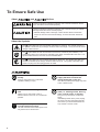
To Ensure Safe Use
About
and
Notices
Used for instructions intended to alert the user to the risk of death or severe
injury should the unit be used improperly.
Used for instructions intended to alert the user to the risk of injury or material
damage should the unit be used improperly.
* Material damage refers to damage or other adverse effects caused with
respect to the home and all its furnishings, as well to domestic animals or
pets.
About the Symbols
The
symbol alerts the user to important instructions or warnings. The specific meaning of
the symbol is determined by the design contained within the triangle. The symbol at left means
"danger of electrocution."
The
symbol alerts the user to items that must never be carried out (are forbidden). The
specific thing that must not be done is indicated by the design contained within the circle. The
symbol at left means the unit must never be disassembled.
The
symbol alerts the user to things that must be carried out. The specific thing that must
be done is indicated by the design contained within the circle. The symbol at left means the
power-cord plug must be unplugged from the outlet.
Do not disassemble, repair, or
modify.
Doing so may lead to fire or abnormal
operation resulting in injury.
Ground the unit with the ground
wire.
Failure to do so may result in risk of
electrical shock in the even of a mechanical
problem
Use only with the power cord
included with this product.
Use with other than the included power cord
may lead to fire or electrocution.
2
Do not use with any electrical power
supply that does not meet the
ratings displayed on the unit.
Use with any other power supply may lead
to fire or electrocution.
Do not use while in an abnormal
state (i.e., emitting smoke, burning
odor, unusual noise, or the like).
Doing so may result in fire or electrical
shock.
Immediately switch off the power, unplug
the power cord from the electrical outlet,
and contact your authorized Roland DG
Corp. dealer or service center.
Do not use with a damaged power
cord or plug, or with a loose
electrical outlet.
When not in use for extended
periods, unplug the power cord from
the electrical outlet.
Use with any other
power supply may
lead to fire or
electrocution.
Failure to do so may
result in danger of
shock, electrocution,
or fire due to
deterioration of the
electrical insulation.
Do not injure or modify the electrical
power cord, nor subject it to
excessive bends, twists, pulls,
binding, or pinching, nor place any
object of weight on it.
When unplugging the electrical
power cord from the power outlet,
grasp the plug, not the cord.
Unplugging by pulling the cord may damage
it, leading to fire or electrocution.
Doing so may
damage the
electrical power
cord, leading to
electrocution or
fire.
Do not attempt to unplug the power
cord with wet hands.
Doing so may
result in electrical
shock.
Install on a stable surface.
Failure to do so
may result in
falling of the unit,
leading to injury.
Unpacking, installation, and moving
are operations that must be carried
out by five or more persons for the
MDX-650A/650 and by four or more
persons for the MDX-500.
Failure to do so may result in falling of the
unit, leading to injury.
(The MDX-650A/
650 weighs 120
kg (264.5 lb.),
and the MDX500 weighs 92
kg (202.8 lb.). )
Do not connect the power cord with
other electrical loads on a single
electrical outlet.
Doing so may generate heat and cause fire.
When moving, grasp the aluminum
base portion at the bottom portion of
the unit, and carry out the operation
with five or more persons for the
MDX-650A/650 or with four or more
persons for the MDX-500.
If grasped by the
rear cover, the
unit may fall,
resulting in injury.
Fasten the spindle, tool, and
material securely in place.
Otherwise they may come loose during
cutting, resulting in injury.
Do not touch the tip of the blade
with your fingers.
Doing so may result in injury.
3
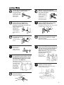
Do not insert the fingers between
the XY table and base or between
the head and Z cover.
Do not insert the fingers between
the T-slot table and arms or between
the head and Z cover.
Doing so may result in injury.
The fingers may be pinched, resulting in
injury.
Head
Z cover
T-slot table
Arm
Do not place anything within the
moving area of the T-slot table.
Wear dust goggles and mask during
use.
The object may bump into the T-slot table
and fall, resulting in injury.
Cutting dust may scatter, causing bodily
injury.
Moving area of
the T-slot table
4
Use a commercially available brush
to remove metal cuttings.
Attempting to use a
vacuum cleaner to
take up metal
cuttings may cause
fire in the vacuum
cleaner.
Do not wear gloves, a necktie or
wide-sleeved clothing.
Do not allow liquids, metal objects
or flammables inside the machine.
They may become
caught in the tool,
resulting in injury.
Such materials
can cause fire.
Do not operate beyond capacity or
subject the tool to undue force.
Perform dry cutting with no cutting
oil.
The tool may break or fly off in a random
direction. If cutting beyond capacity is
mistakenly started, immediately turn off the
EMERGENCY STOP switch.
Such materials can
cause fire.
Do not touch the tool immediately
after cutting operating stops.
The tool may have become hot due to
friction heat and may cause burns if
touched.
When you're finished,
wash your hands to
rinse away all
cuttings.
Switch off the machine and unplug
the power cord from the electrical
outlet before performing cleaning or
maintenance.
Failure to do so may result in injury or
electrical shock.
Please use a vacuum cleaner to
remove cutting dust.
Do not use any blower like airbrush.
Otherwise, dust spread in the air may harm
your health.
About the Labels Affixed to the Unit
These labels are affixed to the body of this product.
The following figure describes the location and content of these messages.
Model name
Rating label
Use a rated power supply.
5
Handle tool with care.
Do not insert fingers
between the head and Z
cover during operation.
Do not insert fingers
between the T-slot table
and arms during operation.
In addition to the
NOTICE
and
: Indicates information to prevent machine breakdown or malfunction and ensure correct use.
: Indicates a handy tip or advice regarding use.
6
symbols, the symbols shown below are also used.
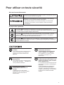
Pour utiliser en toute sécurité
Avis sur les avertissements
Utilisé pour avertir l'utilisateur d'un risque de décès ou de blessure grave en
cas de mauvaise utilisation de l'appareil.
Utilisé pour avertir l'utilisateur d'un risque de blessure ou de dommage
matériel en cas de mauvaise utilisation de l'appareil.
* Par dommage matériel, il est entendu dommage ou tout autre effet
indésirable sur la maison, tous les meubles et même les animaux
domestiques.
À propos des symboles
Le symbole
attire l'attention de l'utilisateur sur les instructions importantes ou les
avertissements. Le sens précis du symbole est déterminé par le dessin à l'intérieur du triangle.
Le symbole à gauche signifie "danger d'électrocution".
Le symbole
avertit l'utilisateur de ce qu'il ne doit pas faire, ce qui est interdit. La chose
spécifique à ne pas faire est indiquée par le dessin à l'intérieur du cercle. Le symbole à
gauche signifie que l'appareil ne doit jamais être démonté.
Le symbole
prévient l'utilisateur sur ce qu'il doit faire. La chose spécifique à faire est
indiquée par le dessin à l'intérieur du cercle. Le symbole à gauche signifie que le fil électrique
doit être débranché de la prise.
Ne pas démonter, réparer ou
modifier.
Le non-respect de cette consigne pourrait
causer un incendie ou provoquer des
opérations anormales entraînant des
blessures.
Mettre l'appareil à la masse avec une
prise de terre.
Le non-respect de cette consigne pourrait
entraîner des décharges
électriques en
cas de problème mécanique.
N'utilisez que le cordon
d'alimentation fourni avec ce
produit.
L’utilisation avec un autre cordon
d’alimentation que celui fourni pourrait
entrainer un risque d’incendie ou
d’électrocution.
Utiliser seulement avec une
alimentation de mêmes
caractéristiques électriques que
celles indiquées sur l'appareil.
Une négligence à ce niveau pourrait
provoquer un incendie ou une
électrocution.
Ne pas utiliser si l'appareil est dans
un état anormal (c'est-à-dire s'il y a
émission de fumée, odeur de brûlé,
bruit inhabituel etc.).
Le non-respect de cette consigne pourrait
provoquer un incendie ou des décharges
électriques.
Couper immédiatement l'alimentation
secondaire et ensuite l'alimentation
principale. Débranchez le fil électrique et
contacter votre revendeur ou votre centre
de service de la société Roland DG
autorisé.
7
Ne pas utiliser avec une fiche ou un
fil électrique endommagé ou avec
une prise mal fixée.
Débrancher le fil lorsque l'appareil
reste inutilisé pendant une longue
période.
Une négligence à
ce niveau pourrait
provoquer un
incendie ou une
électrocution.
Une négligence à ce niveau pourrait
provoquer des décharges électriques,
une électrocution ou
un incendie dû à une
détérioration de
l'isolation électrique.
Ne pas endommager ou modifier le
fil électrique. Ne pas le plier, le
tordre, l'étirer, l'attacher ou le serrer
de façon excessive. Ne pas mettre
d'objet ou de poids dessus.
Saisir la fiche et non le fil électrique
lorsque vous débranchez.
Débrancher en tirant sur le fil pourrait
l'endommager et risquer de provoquer un
incendie ou une électrocution.
Une négligence à
ce niveau pourrait
endommager le fil
électrique ce qui
risquerait de
provoquer une
électrocution ou un
incendie.
Ne pas essayer de débrancher le fil
avec des mains mouillées.
Ne pas brancher d'autres appareils
sur la même prise.
Une négligence à
ce niveau pourrait
provoquer des
décharges
électriques.
Cela pourrait engendrer une surchauffe et
provoquer un incendie.
Installer l’appareil sur une surface
stable.
Pour déplacer l’appareil, saisir la
base en aluminium sous l’appareil. Il
faut cinq personnes ou plus pour
déplacer le MDX-650A/650, et quatre
personnes ou plus pour déplacer le
MDX-500.
Une négligence à
ce niveau pourrait
provoquer la chute
de l’appareil et
entraîner des
blessures.
Il faut cinq personnes ou plus pour
déballer, installer et déplacer le
MDX-650A/650, et quatre personnes
ou plus pour le MDX-500.
Sinon, l'appareil pourrait tomber et
entraîner des blessures.
(Le poids du MDX-650A/650 est de 120 kg,
et celui du MDX-500 est de 92 kg.)
8
Si l'appareil est
saisi par la
plaque du
dessus, il peut
tomber et
entraîner des
blessures.
Ne pas toucher à l’extrémité de la
lame avec vos doigts.
Vous risqueriez de vous blesser en y
touchant.
Fixer fermement le mandrin, l'outil et
le matériel à leur place.
Sinon, ces éléments risquent d'avoir du jeu
lors des coupes, ce qui entraînerait des
blessures.
Ne pas insérer vos doigts entre la
table à fente en T et les bras ou
entre la tête et la plaque Z.
Vous pourriez vous pincer les doigts et vous
blesser.
Ne pas insérer vos doigts entre la
table XY et la base ou entre la tête et
la plaque Z.
Cela pourrait entraîner des blessures.
Ne rien placer dans l'espace mobile
de la table à fente en T.
L'objet pourrait se heurter contre la table à
fente en T et tomber, ce qui pourrait
entraîner des blessures.
Tête
Plaque Z
L'espace
mobile de la
table à fente
en T
Table à
fente en T
Bras
Porter des lunettes de travail et un
masque durant l'utilisation.
Ne pas porter de gants, de cravate
ou de vêtement à manches amples.
Des copeaux pourraient être projetés et
vous blesser.
Ils pourraient se
prendre dans
l'appareil et
entraîner des
blessures.
Utiliser une brosse du commerce
pour retirer les rognures de métal.
Tenter de retirer les
rognures de métal à
l’aide d’un aspirateur
peut faire naître un
incendie dans
l’aspirateur.
Ne pas introduire de liquide, d'objet
métallique ou inflammable dans
l'appareil.
Ne pas utiliser l'appareil au-dessus
de ses capacités ou le soumettre à
une force excessive.
Ce genre de
matériel peut
provoquer un
incendie.
L'outil pourrait se briser ou être projeté
dans une direction indéterminée. Si vous
commencez par inadvertance une coupe
au-dessus de la capacité de l'appareil,
l'éteindre immédiatement à l'aide du bouton
d'urgence.
9
Ne pas toucher l'outil
immédiatement après une coupe.
L'outil pourrait avoir chauffé avec la friction
et vous causer des brûlures.
Couper le contact et débrancher le
câble d’alimentation du réceptacle
avant de procéder au nettoyage ou à
l’entretien de l’appareil.
Une négligence à ce niveau pourrait
provoquer des blessures ou une
électrocution.
Quand vous avez
terminé d'utiliser
l'appareil, laver vos
mains pour bien
enlever tous les
copeaux.
Utiliser un aspirateur pour nettoyer
les copeaux. N'utiliser aucun
appareil soufflant de l'air comme un
sèche-cheveux.
La poussière répandue dans l'air pourrait
nuire à votre santé.
À propos des étiquettes collées sur l'appareil
Ces étiquettes sont collées à l'extérieur de l'appareil.
Les dessins suivants indiquent l'endroit et le contenu des messages.
Nom du modèle
Étiquette des caractéristiques
électriques
Utiliser l'alimentation appropriée
10
Manipuler l'outil
avec précaution.
Ne pas insérer vos
doigts entre la tête et la
plaque Z quand l'appareil
est en marche.
Ne pas insérer vos doigts
entre la table à fente en T
et les bras quand
l'appareil est en marche.
11
MEMO
12
Part 1 Setting Up
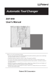
How The Manuals Are Organized
The manuals are organized as follows. Refer to the appropriate one according to the purpose at hand.
1
USER'S MANUAL 1
"Setup & Maintenance"
This describes installation, connection, preparations for
starting cutting, and the care and maintenance of the
machine.
When cutting
using RML-1
2
USER'S MANUAL 2
"Cutting Using the Included Software"
This describes operation methods when using the
included software to perform cutting.
When cutting
using NC codes
3
USER'S MANUAL 3
"Cutting Using NC Codes"
This describes operation methods when using NC codes
to perform cutting.
NC code
PROGRAMMER'S MANUAL
This describes the NC codes. It explains the basics of
programming as well as each code.
13
Part 1 Setting Up
Part 1
Setting Up
1-1 Checking the Accessories
The following items are packed together with the unit.
T-slot clamps : 4
Bolts (5 x 25 mm) : 4
Wrench (10 mm (3/8 in.))
(For installing the work)
(For installing the T-slot clamp)
* These bolts are for the substitutions when
the original bolts on the T-slot clamp are
too long.
(For securing the T-slot clamps in place)
Z0 position sensor
Hexagonal wrench
Belt for high-torque spindle
Key connector
Ferrite corer
* Except for MDX-500
Power cord
* The machine does not run unless
this is inserted.
Roland Software Package
CD-ROM
14
USER'S MANUAL
(1 Setup & Maintenance)
(2 Cutting Using the Included Software)
(3 Cutting Using NC codes)
NC Code
PROGRAMMER'S MANUAL
Part 1 Setting Up
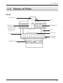
1-2 Names of Parts
Front
Fan motor cover
Head
Spindle cover
* When the spindle cover
is open, the machine
does not run (see "1-4
Description of the
Spindle Area").
Arm
Bellows cover
Arm
Base cover
T-slot table
(XY Table)
Operation Panel
15
Part 1 Setting Up
Right Side
Power switch
Power connector
Expansion connector
(EXT.4)
*MDX-650A only
Left Side
Expansion connector
(EXT.1)
Serial connector
Parallel connector
Expansion connector
(EXT.2)
Expansion connector
(EXT.3)
Z0 position sensor jack
16
Part 1 Setting Up
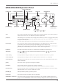
MDX-650A/650 Operation Panel
TOOL DOWN key
[COPY] key
Liquid-crystal display
[PAUSE] key
[XY/A] key
TOOL UP key
[Z] key
[JOG] key
FAST FEED key
[SPINDLE] key
[ENTER] key
[EXIT] key
Arrow keys
([ ] [ ] [
] [
Dial
EMERGENCY
STOP switch
])
Dial
This is used to change the selection on the display menu, or during coordinate view to perform jogging of
the XY table or tool (Z axis) or to change the speed of the spindle motor.
[JOG] key
When the display is at coordinate view, this changes selects the item you want to set (jogging of the XY table
or tool [Z axis] or spindle-motor speed). When the instruction set is set to NC code, this also selects the
displayed coordinate system.
This also switches the Y and A axes when the rotary axis unit (optionally available) is installed.
[ENTER] key
This is pressed to confirm a selection on the display menu, a value that has been set, or other selections.
Use the dial to choose a menu item, then press [ENTER] to go down to the next level.
When you want to change a present setting value or selection, make the selection with the dial, then press
[ENTER]. The confirmed setting value or selection is shown between angle brackets.
[EXIT] key
Press this to return to the main menu or to switch between coordinate view and menu view.
Arrow keys
The [ ] [ ] keys move the XY table forward and backward, and the [
head to the left and right.
TOOL UP key
This key makes the cutting tool (blade) move in a positive direction on the Z axis (i.e., upward).
TOOL DOWN key
This key makes the cutting tool move in a negative direction on the Z axis (i.e., downward).
FAST FEED key
When pressed at the same time as an arrow key, the TOOL UP key, or the TOOL DOWN key, this makes
the movement faster.
[Z] key
This sets the Z-axis origin point for workpiece coordinates.
[XY/A] key
This set the X- and Y-axis origin point for workpiece coordinates.
This also sets the A-axis origin point when the rotary axis unit (optionally available) is installed.
[SPINDLE] key
This starts and stops rotation of the spindle. To start rotation, hold down the key for one second or longer.
When the spindle cover is open, the spindle does not rotate.
[PAUSE] key
When pressed during cutting, operation is paused.
[COPY] key
This performs cutting again with the data in the data buffer.
EMERGENCY STOP switch
This switch cuts the power supply and forces the machine to stop, regardless of whether operation is in
progress. Press the EMERGENCY STOP switch immediately if dangerous or abnormal operation occurs.
] [
] keys move the
17
Part 1 Setting Up
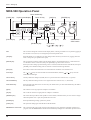
MDX-500 Operation Panel
TOOL DOWN key
[COPY] key
Liquid-crystal display
[PAUSE] key
[XY] key
TOOL UP key
[Z] key
[JOG] key
FAST FEED key
[SPINDLE] key
[ENTER] key
[EXIT] key
Arrow keys
([ ] [ ] [
] [
Dial
EMERGENCY
STOP switch
])
Dial
This is used to change the selection on the display menu, or during coordinate view to perform jogging of
the XY table or tool (Z axis) or to change the speed of the spindle motor.
[JOG] key
When the display is at coordinate view, this changes selects the item you want to set (jogging of the XY
table or tool [Z axis] or spindle-motor speed).
[ENTER] key
This is pressed to confirm a selection on the display menu, a value that has been set, or other selections.
Use the dial to choose a menu item, then press [ENTER] to go down to the next level.
When you want to change a present setting value or selection, make the selection with the dial, then press
[ENTER]. The confirmed setting value or selection is shown between angle brackets.
[EXIT] key
Press this to return to the main menu or to switch between coordinate view and menu view.
Arrow keys
The [ ] [ ] keys move the XY table forward and backward, and the [
head to the left and right.
TOOL UP key
This key makes the cutting tool (blade) move in a positive direction on the Z axis (i.e., upward).
TOOL DOWN key
This key makes the cutting tool move in a negative direction on the Z axis (i.e., downward).
FAST FEED key
When pressed at the same time as an arrow key, the TOOL UP key, or the TOOL DOWN key, this makes
the movement faster.
[Z] key
This sets the Z-axis origin point for workpiece coordinates.
[XY] key
This set the X- and Y-axis origin point for workpiece coordinates.
[SPINDLE] key
This starts and stops rotation of the spindle. To start rotation, hold down the key for one second or longer.
When the spindle cover is open, the spindle does not rotate.
[PAUSE] key
When pressed during cutting, operation is paused.
[COPY] key
This performs cutting again with the data in the data buffer.
EMERGENCY STOP switch
This switch cuts the power supply and forces the machine to stop, regardless of whether operation is in
progress. Press the EMERGENCY STOP switch immediately if dangerous or abnormal operation occurs.
18
] [
] keys move the
Part 1 Setting Up
1-3 Setting Up and Connection Setting
Setting Up
Install on a stable surface.
Failure to do so
may result in falling
of the unit, leading
to injury.
Do not place anything within the
moving area of the T-slot table.
The object may bump into the T-slot table
and fall, resulting in injury.
Moving area of
the T-slot table
Unpacking, installation, and moving
are operations that must be carried
out by five or more persons for the
MDX-650A/650 and by four or more
persons for the MDX-500.
Failure to do so may result in falling of the
unit, leading to injury.
(The MDX-650A/
650 weighs 120
kg (264.5 lb.),
and the MDX500 weighs 92
kg (202.8 lb.). )
When moving, grasp the aluminum
base portion at the bottom portion of
the unit, and carry out the operation
with five or more persons for the
MDX-650A/650 or with four or more
persons for the MDX-500.
If grasped by the
rear cover, the
unit may fall,
resulting in injury.
NOTICE
Use within a temperature range of 5 to 40°C (41 to 104°F) and within a humidity range of 35 to 80%.
Do not place any objects on the main unit's head.
When the unit is mounted on a stand with casters, be sure to lock the caster stoppers securely.
To prevent accidents, do not install in any of the following types of areas.
• Avoid use in areas subject to strong electric noise.
• Avoid use in areas subject to high humidity or dust.
• The machine generates heat when used, and should not be installed in an area with poor heat radiation
characteristics.
• Do not install in an area subject to strong vibration.
19
Part 1 Setting Up
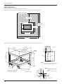
MDX-650A/650
The required dimensions for installation space are shown.
"Maintenance space" is the space needed by a service technician when performing maintenance.
Maintenance space
900 mm
(35-7/16 in.)
Installation space
Rear
Main unit
2600 mm
(102-3/8 in.)
1200 mm
(47-1/4 in.)
Front
1300 mm
(51-3/16 in.)
2200 mm
(86-5/8 in.)
When you are installing on a stand, use a stand with specifications equivalent to those shown below.
40
5
7
Y
FIG 2
R8
X
7
750 mm
(29-1/2 in.)
X
75
590 mm
(23-1/4 in.)
Ceiling panel
thickness: 9 mm
Unit: mm
(17.5) 17.5
R4
103
(40- 0 mm
9/16
in.)
mm
1090 5/16
1
(42- )
in.
Y
FIG 1 Cross-sectional secondary moment
lx=75.3
FIG 1
R3
Cross-sectional secondary
moment
lx=3.53 ly=3.53 (cm4)
Y
17.5
Rated load: 100 kgf
X
X
R4
.5
5
40
*Welded structure
Y
40
20
(cm4)
FIG 2
5
Rated load: 1500 kgf
ly=12.2
17.5
Unit: mm
Part 1 Setting Up
MDX-500
The required dimensions for installation space are shown.
"Maintenance space" is the space needed by a service technician when performing maintenance.
Maintenance space
900 mm
(35-7/16 in.)
Installation space
Rear
Main unit
2300 mm
(90-9/16 in.)
900 mm
(35-7/16 in.)
Front
1100 mm
(43-5/16 in.)
2000 mm
(78-1/8 in.)
When you are installing on a stand, use a stand with specifications equivalent to those shown below.
40
R4
5
Y
FIG 2
R8
X
7
750 mm
(29-1/2 in.)
X
75
590 mm
(23-1/4 in.)
Ceiling panel
thickness: 9 mm
Unit: mm
(17.5) 17.5
7
790
(31- mm
1/8 i
n.)
mm
900 6 in.)
/
71
(35-
Y
FIG 1 Cross-sectional secondary moment
lx=75.3
FIG 1
R3
Cross-sectional secondary
moment
lx=3.53 ly=3.53 (cm4)
Y
17.5
Rated load: 100 kgf
X
5
X
.5
R4
40
*Welded structure
(cm4)
FIG 2
5
Rated load: 1500 kgf
ly=12.2
Y
40
17.5
Unit: mm
21
Part 1 Setting Up
Connection
Do not use with any electrical power
supply that does not meet the
ratings displayed on the unit.
Use with any other power supply may lead
to fire or electrocution.
Ground the unit with the ground
wire.
Failure to do so may result in risk of
electrical shock in the even of a mechanical
problem
Use only with the power cord
included with this product.
Use with other than the included power cord
may lead to fire or electrocution.
Do not connect the power cord with
other electrical loads on a single
electrical outlet.
Doing so may generate heat and cause fire.
NOTICE
Be sure that the power to both the computer and the main unit is switched off when connecting the cable.
Securely connect the power cord, computer I/O cable and so on so that they will not be unplugged and cause
failure during operation. Doing so may lead to faulty operation or breakdown.
Right side
Power connector
Power outlet
Power cord
22
Part 1 Setting Up
*Be sure the machine's power is turned off before
you insert or remove the key connector.
Left side
Insert the included key
connector here. When the
key connector is not
inserted, the machine does
not accept
sent data and its
spindle does
not turn.
Parallel connector
Serial connector
Z0 position sensor jack
Z0 position sensor
For IBM PC or PC compatibles
Serial connector
Parallel connector
Serial connector
Parallel connector
Secure the
cable in place
with the clips.
Secure the
cable in place
with the screw.
Parallel interface cable (Printer cable)
Crossover serial cable (RS-232C)
< MDX-650A/650 only >
Attach the included ferrite core at the location on the
connection cable shown in the figure.
* Cables are available separately. One which
you are sure matches the model of computer
being used should be selected.
20 to 30 mm (13/16 to 1-3/16 in.)
from the connector on the machine
23
Part 1 Setting Up
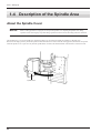
1-4 Description of the Spindle Area
About the Spindle Cover
NOTICE
When a cutting operation is in progress, do not open the spindle cover. Opening the spindle cover during
operation causes an emergency stop. Data during operation becomes invalid, and cutting cannot be continued.
The machine has a cover on the spindle area. Open the spindle cover to perform such tasks as installing or changing tools.
Because of the danger posed by accidental operation while the hands are in contact with the rotating portion, the unit does not operate
while the spindle cover is open. Not only does the spindle motor not rotate, but the head and the T-slot table also cannot be moved.
Spindle cover
24
Part 1 Setting Up
High-torque Spindle and High-speed Spindle
The machine can use either of two types of spindle units: a high-torque spindle or a high-speed spindle (spindle units are sold separately).
The setting for the type of spindle installed (high-torque or high-speed) must be made on the machine. (Refer to "1-6 Choosing the
Spindle Type.")
NOTICE
When cutting objects made of materials that produce minute cuttings or dust, such as foamed material or
gypsum, use the optionally available vacuum adapter for chip cleaning. Otherwise cuttings may get inside the
machine, shorting the service life of the spindle unit.
High-torque Spindle
High-speed Spindle
This spindle is designed for torque. Speed is from 3,000 to
12,000 rpm. It is mainly suited to cutting using an end mill
(modeling).
This spindle is designed for speeds from 5,000 to 20,000 rpm.
Torque is not as high as the high-torque spindle. It is mainly
suited to cutting using an engraving tool.
Installable Optional Items for Different Spindles
Collet
Cutting Tool
Vacuum adapter
High-torque Spindle
ø6 mm
*ZS-650T
(For the MDX-650A/650)
*ZS-500T
(For the MDX-500)
ø6 mm
End mill
*ZAD-500T
Standardly included with the spindle
ø10, ø8, ø6.35, ø5, ø4, ø3.2, ø3 mm
ø10, ø8, ø6.35, ø5, ø4, ø3.2, ø3 mm
*ZC-500T (Collet set)
End mill
ø6.35, ø4.36 mm
*ZC-500TE (Collet and holder set)
ø6.35, ø4.36 mm
Engraving cutter
ø4.36 mm
ø4.36 mm
Standardly included with the spindle
Engraving cutter
ø6, ø5, ø4, ø3 mm
*ZC-23 (Collet set)
ø6, ø5, ø4, ø3 mm
ø6.35 mm
ø6.35 mm
*ZC-23-6.35
End mill
High-speed Spindle
*ZS-500SH
*ZAD-500S
End mill
* Indicates option part number. For tool part numbers, see the supply-part catalog.
25
Part 1 Setting Up
High-torque Spindle (Optional) Set
Make sure the following items are included with the high-torque spindle (ZS-650T/ZS-500T).
Spindle unit
Collet
Wrenches
(24 mm (15/16 in.),
13 mm (1/2 in.))
Screws: 4
Hexagonal screw driver
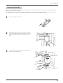
Installing the High-torque Spindle (ZS-650T/ZS-500T)
Fasten the spindle, tool, and
material securely in place.
Otherwise they may come loose during
cutting, resulting in injury.
1
Align the pin on the back of the spindle unit with the pinhole on the slider, and support it with your hand.
Slider
Pin hole
26
Part 1 Setting Up
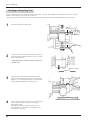
2
Insert the screw at the location shown in the figure, then
tighten using the included hexagonal screwdriver.
3
Pass the belt through under the motor pulley and engage
on the spindle pulley.
Spindle belt
Spindle pulley
Motor pulley
4
While pressing down on the belt engaged on the spindle
pulley, turn the motor pulley in the direction of the arrow
to attach the belt.
5
Turn the motor pulley several times so as to position the
belt on the motor pulley and spindle pulley as shown in
the figure.
27
Part 1 Setting Up
Installing the Tool
Do not touch the tip of the blade
with your fingers.
Fasten the spindle, tool, and
material securely in place.
Doing so may result in injury.
Otherwise they may come loose during
cutting, resulting in injury.
Do not touch the tool immediately
after cutting operating stops.
The tool may have become hot due to
friction heat and may cause burns if
touched.
NOTICE
Use the correct tool for the material to be cut and the cutting method.
Do not attach the collet without the end mill and tighten with the wrench. Doing so may make it impossible to install
an end mill the next time used.
When installing an end mill, detach the blade holder. If you try to perform machining with the blade holder installed,
the vibration may make it come loose and fall off.
Be sure to use the wrench included with the unit. Using a wrench other than included one may result in
overtightening, making it impossible to remove the collet or damaging the spindle.
Use caution to prevent the cutting tool from falling out, otherwise the cutting tool may be damaged.
Be careful not to drop the collet.
Doing so may cause the collet to deform or break, making it impossible to install a tool.
28
Part 1 Setting Up
Installing an End Mill
Install a collet that matches the shank diameter of the end mill. The combination of end mill and collet is correct if the diameter of the
end mill just fits in the hole in the collet.
The collet included with the high-torque spindle has a diameter of 6 mm. When using an end mill having a diameter other than 6 mm
(i.e., a diameter of 10, 8, 6.35, 5, 4, 3.2, or 3 mm), the optionally available collet set (ZC-500T) is required.
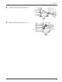
1
Insert the end mill into the collet.
Collet
End mill
2
Insert the assembly from step 1 into the lower part of the
spindle. While supporting the end mill with your hand to
keep it from falling, rotate the spindle pulley to secure in
place.
3
Use the included wrenches to tighten the spindle pulley
and collet (150 to 200 kgf·cm).
Spindle pulley
Spindle pulley
Wrench
(24 mm(15/16 in.))
Wrench
(13 mm(1/2 in.))
29
Part 1 Setting Up
Installing an Engraving Tool
Install a cutter holder and collet which are suitable for the cutter to be used. The combination of end mill and collet is correct if the
diameter of the end mill just fits in the hole in the collet.
Using an engraving tool with the high-torque spindle requires the optionally available collet and blade-holder set (ZC-500TE).
1
Install the blade holder and the collet.
Blade-holder
Wrench
(24 mm(5/16 in.))
Collet
2
Wrench
(13 mm(1/2 in.))
Use the arrow keys and the tool-down key to position the
tip of the head approximately 20 mm (13/16 in.) from the
surface of the workpiece.
* When attempting to move the head, first close the
spindle cover.
20 mm (13/16 in.)
Workpiece
3
Insert the cutter into the hole in the cutter holder and
position the tip so that it gently touches the surface of the
workpiece. Use the hexagonal screwdriver included with
the ZC-500TE to tighten the tool retaining screw.
Workpiece
4
30
Use the operation panel to set the Z-axis origin point. The
Z-axis origin is the reference point for raising and
lowering the spindle.
For information on how to make the setting, refer to
User's Manual 2 or User's Manual 3, depending on the
command set you're using.
Part 1 Setting Up
Attaching the Brush Adapter for Chip Cleaning for the High-torque Spindle (ZAD-500T)
Use a commercially available brush
to remove metal cuttings.
NOTICE
Attempting to use a
vacuum cleaner to
take up metal
cuttings may cause
fire in the vacuum
cleaner.
Use a vacuum cleaner that lets you adjust
the amount of suction and is equipped with
an overload protector.
Always allow a minimum gap of 30 cm
(11-13/16 in.) on the side where the
vacuum hose exits. The vacuum hose
must have sufficient space in which to
move. When the vacuum hose cannot
move smoothly, it can cause malfunctions
or errors in operation.
When the fitting diameters do not match or when the vacuum duct cannot be inserted into the suction opening of the
vacuum cleaner, use strong commercial tape (cloth or electrical) to join the fittings. The duct diameter of the ZAD500T is 32 mm (1-5/16 in.).
Attaching the optionally available brush adapter for chip cleaning (ZAD-500T) to the high-torque spindle (ZS-650T/ZS-500T) makes it
possible to take up cutting dust with your vacuum cleaner as you perform cutting.
This is mainly of use when performing cutting using an end mill (modeling).
Items Included with
the ZAD-500T
Screws: 2
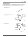
1
Vacuum duct
Chip-cleaning brush
Vacuum adapter
Fasten the touch fastener to attach the chipcleaning brush to the brush adapter for chip
cleaning.
2
Install the brush adapter for chip cleaning on the machine’s
spindle portion.
High-torque spindle
Fastener
* Even when the brush adapter for chip cleaning
is installed on the machine, you can change the
tool by unfastening the touch fastener.
Screw
Screw
31
Part 1 Setting Up
High-speed Spindle (Optional) Set
Make sure the following items are included with the high-speed spindle (ZS-500SH).
Spindle belt
Wrenches
(24 mm (15/16 in.),
10 mm (3/8 in.))
Hexagonal screw drivers
Screws: 4
Spindle unit
These are installed
on the spindle unit.
Collet
(4.36 mm (3/16 in.))
Cutter holder
(4.36 mm (3/16 in.))
Installing the High-speed Spindle (ZS-500SH)
Fasten the spindle, tool, and
material securely in place.
Otherwise they may come loose during
cutting, resulting in injury.
1
Align the pin on the back of the spindle unit with the pinhole on the slider, and support it with your hand.
Slider
Pin hole
32
Part 1 Setting Up
2
Insert the screw at the location shown in the figure, then
tighten using the included hexagonal screwdriver.
3
Engage the belt in the groove on the motor pulley then
pull by hand to hand it on the spindle pulley.
Spindle pulley
Groove
Spindle belt
33
Part 1 Setting Up
Installing the Tool
Do not touch the tip of the blade
with your fingers.
Fasten the spindle, tool, and
material securely in place.
Doing so may result in injury.
Otherwise they may come loose during
cutting, resulting in injury.
Do not touch the tool immediately
after cutting operating stops.
The tool may have become hot due to
friction heat and may cause burns if
touched.
NOTICE
Use the correct tool for the material to be cut and the cutting method.
When installing an end mill, attach only the collet without the tool, and do not tighten using the wrench. Doing so
may make it impossible to install a tool the next time used.
When installing an end mill, detach the blade holder. If you try to perform machining with the blade holder installed,
the vibration may make it come loose and fall off.
Be sure to use the wrench included with the unit. Using a wrench other than included one may result in
overtightening, making it impossible to remove the collet or damaging the spindle.
Use caution to prevent the cutting tool from falling out, otherwise the cutting tool may be damaged.
34
Part 1 Setting Up
Installing an Engraving Tool
Install a cutter holder and collet which are suitable for the
cutter to be used. The combination of end mill and collet is
correct if the diameter of the end mill just fits in the hole in the
collet.
The collet and blade holder included with the high-speed
spindle has a diameter of 4.36 mm.
Install the blade holder and the collet.
Blade-holder
Wrench
(24 mm(15/16 in.))
Collet
Wrench
(10 mm(3/8 in.))
*When Using the Depth Regulator Nose
Using the depth regulator nose makes it possible to engrave workpiece of nonuniform thickness at same depth.
(Because engraving is performed while the tip of the depth regulator nose is in contact with the workpiece, the surface of the workpiece
may be damaged.)
1
Rotate the depth regulator nose in the direction of arrow 2
in the figure to tighten it completely.
Bottom of the head
2
1
2
This determines the engraving depth (cutting-in amount).
The scale on the micrometer dial assembly has 25
grooves, with one groove corresponding to an engraving
depth of 0.0254 mm (0.001 in.). (One full turn of the
scale corresponds to an engraving depth of 0.635 mm
(0.025 in.).) Rotate the scale in the direction of the arrow
shown in the figure by an amount equal to or greater than
the engraving depth.
For example, when engraving to a depth of 0.5 mm
(0.0197 in.), the scale should be rotated by 20 grooves
(approximately one full turn). For engraving at a depth of
1.5 mm (0.0591 in.), rotate the scale by 59 grooves
(approximately three turns).
3
Turn the nut in the direction of the arrow to loosen
completely.
Bottom of the head
Nut
35
Part 1 Setting Up
4
Use the arrow keys to position the head over the
workpiece.
* When attempting to move the head, first close the
spindle cover.
5
Press the TOOL DOWN key to bring the depth regulator
nose in contact with the surface of the workpiece.
* When attempting to move the head, first close the
spindle cover.
Workpiece
If the depth regulator nose does not reach the surface of the workpiece even when the
tool down (-Z) key is held down, rotate the micrometer dial in the direction shown by the
arrow in the figure to extent the tip of the depth regulator nose to the workpiece surface.
If the tip of the depth regulator nose doesn't reach the surface of the workpiece because
the workpiece is too thin, place a board between the workpiece and the table.
Alternatively, use the optionally available spacer for the T-slot table (ZA-600/500 series)
to raise the height of the table.
6
Set the Z-axis origin point at the location you set in step
5. The Z-axis origin is the reference point for raising and
lowering the spindle.
For information on how to make the setting, refer to
User's Manual 2 or User's Manual 3, depending on the
command set you're using.
7
Insert the cutter into the hole in the cutter holder, and use
the hexagonal screwdriver (small) that comes with the
machine to tighten the cutter mounting screw.
Workpiece
36
Part 1 Setting Up
8
Raise the spindle with the tool up (+Z) key.
9
Rotate the dial in the direction of the arrow shown in the
figure to extend the cutter to the engraving depth (cuttingin amount).
Move the cutter out just enough for the necessary
engraving depth.
The lines printed on the dial indicate 0.0254 mm (0.001
in.) for each mark. For instance, to set a cutting depth of
0.5 mm (0.0197 in.), rotate an 20 mark portion.
10
* When attempting to move the head, first close the
spindle cover.
Bottom of the head
Engraving depth
Use a program or the operation panel to set the tool-down position. Set this at a cutting-in amount about 2 to 3 mm deeper than
the cutting-in amount set using the micrometer dial (the actual cutting-in amount).
Setting a cutting-in amount that corresponds to the difference in height between the highest and lowest locations on the
workpiece allows the tip of the depth regulator nose to be constantly pressed against the surface of the workpiece and enables
engraving at a uniform depth.
* The spindle stroke due to the nut is approximately 5 mm (3/16 in.).
It is not possible to absorb differences in height greater than 5 mm (3/16 in.).
Spindle stroke
Workpiece
Difference in height between
the highest and lowest locations
37
Part 1 Setting Up
*When Not Using the Depth Regulator Nose
If you do not use the depth regulator nose, take a table workpiece made of ABS plastic about 10 mm (3/8 in.) thick,
secure it in place on the included table, and perform surface leveling. By using this as the table surface, you can carry
out engraving at a uniform depth.
1
Turn the nut in the direction of the arrow to tighten it
securely.
Nut
2
Press the arrow keys and the tool down (-Z) key to move
the tip of the head to a position close to the surface of the
workpiece
* When attempting to move the head, first close the
spindle cover.
Workpiece
3
Insert the cutter into the hole in the cutter holder and
position the tip so that it gently touches the surface of the
workpiece. Use the hexagonal screw driver included with
the ZC-500TE to tighten the screw.
Workpiece
4
38
Use the operation panel to set the Z-axis origin point. The
Z-axis origin is the reference point for raising and
lowering the spindle.
For information on how to make the setting, refer to
User's Manual 2 or User's Manual 3, depending on the
command set you're using.
Part 1 Setting Up
Installing an End Mill
Install a collet that matches the shank diameter of the end mill. The combination of end mill and collet is correct if the diameter of the
end mill just fits in the hole in the collet.
Using an end mill with the high-speed spindle requires the optionally available collet set (ZC-23) or collet (ZC-23-6.35).
1
Insert the end mill into the collet.
Collet
End mill
2
Insert the assembly from step 1 into the lower part of the
spindle, and turn the collet to secure it in place and keep
the end mill from falling out.
3
Use the included wrenches to tighten the spindle pulley
and collet (150 to 200 kgf·cm).
Spindle pulley
Wrench
(24 mm(15/16 in.))
Wrench
(10 mm(3/8 in.))
39
Part 1 Setting Up
Attaching the Brush Adapter for Chip Cleaning for the High-speed Spindle (ZAD-500S)
Use a commercially available brush
to remove metal cuttings.
NOTICE
Attempting to use a
vacuum cleaner to
take up metal
cuttings may cause
fire in the vacuum
cleaner.
Use a vacuum cleaner that lets you adjust
the amount of suction and is equipped with
an overload protector.
Always allow a minimum gap of 30 cm
(11-13/16 in.) on the side where the
vacuum hose exits. The vacuum hose
must have sufficient space in which to
move. When the vacuum hose cannot
move smoothly, it can cause malfunctions
or errors in operation.
When the fitting diameters do not match or when the vacuum duct cannot be inserted into the suction opening of the
vacuum cleaner, use strong commercial tape (cloth or electrical) to join the fittings. The duct diameter of the ZAD500T is 32 mm (1-5/16 in.).
Attaching the optionally available brush adapter for chip cleaning (ZAD-500S) to the high-speed spindle (ZS-500SH) makes it possible
to take up cutting dust with your vacuum cleaner as you perform cutting.
This is mainly of use when performing cutting using an engraving tool.
Items Included with
the ZAD-500S
Hooks: 2
1) Take off the cap and insert
the hook.
Vacuum hose
Vacuum duct
Vacuum adapter
1
2
2) Secure the vacuum hose
in place.
Cap
3
1) Take off the cap and insert
the hook.
Tighten
Cap
2) Secure the vacuum hose
in place.
40
Part 1 Setting Up
1-5 Selection of the Command Set
The first thing to do is to select the command set to use.
To perform output from the Windows program through the driver, choose "RML-1."
The driver is installed from the included Roland Software Package. For more information on how to install it, take a look at
"User's Manual 2_Cutting Using the Included Software."
Selecting the Command Set
Immediately after switching on the power, use the display to choose either RML-1 or NC code. Follow the steps below to choose the
command set.
Once the command set has been selected, it can only be changed by switching the power off and on again. When you turn on the power,
the display shows the command last selected in blinking text. If you don’t want to change this command, press the [ENTER] key.
1
2
Turn the dial to move the arrow to the command set to
use, then press the [ENTER] key.
Hit "ENTER" >RML-1
Select MODE NC-CODE
[RML-1] or
[NC-CODE]
Display screen
MDX-500
Roland DG Corp.
The method of operation during cutting differs according to the selected command set. If you selected RML-1, see "User's Manual 2 -Cutting Using the Included Software." If you selected NC code, see "User's Manual 3 -- Cutting Using NC Codes.
41
Part 1 Setting Up
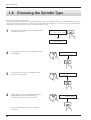
1-6 Choosing the Spindle Type
This sets the type of the installed spindle.
If a high-torque spindle is installed, choose [HIGH TORQUE]. If a high-speed spindle is installed, choose [HIGH SPEED]. An incorrect
selection may result in insufficient power to the motor and make normal cutting impossible, or conversely may apply power beyond the
rated capacity to the motor and cause an error to be displayed during cutting.
1
If the display shows coordinates, press the [ENTER] key
to display the main menu.
*X
Z
0
1500
Y
0
5000 RPM
>1 SPEED SETTING
2 SPINDLE RPM
2
Turn the dial to move the arrow to [OTHERS], then press
the [ENTER] key.
3
Turn the dial to move the arrow to [SPINDLE UNIT],
then press the [ENTER] key.
4
Turn the dial to move the arrow to [HIGH TORQUE] or
[HIGH SPEED], then press the [ENTER] key.
The selected mode is enclosed in angle brackets.
>10 OTHERS
11 To Coordinate
10>2 SPINDLE UNIT
3 BUZZER
10-2 SPINDLE UNIT
<HIGH TORQUE>
or HIGH SPEED
* To go back to the main menu, press the [EXIT] key
several times.
42
Part 1 Setting Up
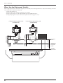
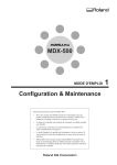
1-7 The Cutting Area
MDX-650A/650
The maximum cutting area is 650 mm x 450 mm x 155 mm (25-9/16 in. x 17-11/16 in. x 6-1/16 in.). If you selected RML-1 as the
command set, then when converted to coordinate values (step size: 1/100 mm), (x, y, z) = (50,000, 33,000, 10,500).
The actual cutting area differs according to the type of spindle installed.
When Use the High-torque Spindle (ZS-650T)
When a high-torque spindle (ZS-650T) is installed, the range that you can actually cut (in the height direction) is subject to the following
restrictions and is smaller than the maximum cutting range described earlier.
105 mm
(4-1/8 in.)
80 mm
(3-1/8 in.)
22 mm
(7/8 in.)
155 mm(6-1/16 in.)
(Z-axis movable range)
- Length of the installed tool
- Position of the XY table where the workpiece to cut is loaded
- If using a spacer for the T-slot table (ZA-600/500 series), the height of the spacer
X-rail bottom
surface
T-slot table upper
surface when
using a spacer
(ZA-508)
T-slot table
upper surface
43
Part 1 Setting Up
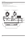
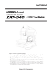
When Use the High-speed Spindle
When a high-speed spindle is installed, the range that you can actually cut (in the height direction) is subject to the following restrictions
and is smaller than the maximum cutting range.
- Length of the installed tool
- Position of the XY table where the workpiece to cut is loaded
- If using a spacer for the T-slot table (ZA-600/500 series), the height of the spacer
- If using a depth regulator nose, the stroke of the spindle due to the nut (approx. 5 mm)
130 mm
(5-1/8 in.)
55 mm
(2-3/16 in.)
112 mm
(4-3/8 in.)
155 mm(6-1/16 in.)
(Z-axis movable range)
If not using the depth regulator nose
(nut tightened)
12 mm
(1/2 in.)
94.6 mm
(3-3/4 in.)
5.4 mm
(3/16 in.)
155 mm(6-1/16 in.)
(Z-axis movable range)
If using the depth regulator nose
(nut loosened)
X-rail bottom
surface
T-slot table upper
surface when
using a spacer
(ZA-613)
T-slot table
upper surface
44
Part 1 Setting Up
MDX-500
The maximum cutting area is 500 mm x 330 mm x 105 mm (19-5/8 in. x 12-15/16 in. x 4-1/8 in.). If you selected RML-1 as the
command set, then when converted to coordinate values (step size: 1/100 mm), (x, y, z) = (50,000, 33,000, 10,500).
The actual cutting area differs according to the type of spindle installed.
When Use the High-torque Spindle (ZS-500T)
When a high-torque spindle (ZS-500T) is installed, the range that you can actually cut (in the height direction) is subject to the following
restrictions and is smaller than the maximum cutting range described earlier.
55 mm
(2-3/16 in.)
80 mm
(3-1/8 in.)
22 mm
(7/8 in.)
105 mm(4-1/8 in.)
(Z-axis movable range)
- Length of the installed tool
- Position of the XY table where the workpiece to cut is loaded
- If using a spacer for the T-slot table (ZA-600/500 series), the height of the spacer
X-rail bottom
surface
T-slot table upper
surface when
using a spacer
(ZA-508)
T-slot table
upper surface
45
Part 1 Setting Up
When Use the High-speed Spindle
When a high-speed spindle is installed, the range that you can actually cut (in the height direction) is subject to the following restrictions
and is smaller than the maximum cutting range.
- Length of the installed tool
- Position of the XY table where the workpiece to cut is loaded
- If using a spacer for the T-slot table (ZA-600/500 series), the height of the spacer
- If using a depth regulator nose, the stroke of the spindle due to the nut (approx. 5 mm)
80 mm
(3-1/8 in.)
55 mm
(2-3/16 in.)
62 mm
(2-7/16 in.)
105 mm(4-1/8 in.)
(Z-axis movable range)
If not using the depth regulator nose
(nut tightened)
12 mm
(1/2 in.)
44.6 mm
(1-3/4 in.)
5.4 mm
(3/16 in.)
105 mm(4-1/8 in.)
(Z-axis movable range)
If using the depth regulator nose
(nut loosened)
X-rail bottom
surface
T-slot table upper
surface when
using a spacer
(ZA-508)
T-slot table
upper surface
46
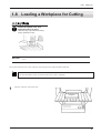
Part 1 Setting Up
1-8 Loading a Workpiece for Cutting
Fasten the spindle, tool, and
material securely in place.
Otherwise they may come loose during
cutting, resulting in injury.
NOTICE
When mounting a vise or loading a workpiece while a tool is installed, take care to avoid being injured by the
tool.
This section describes how to load a workpiece when using the T-slot clamp included with the unit.
A spacer for the T-slot table (ZA-600/500 series) is optionally available and should be purchased if needed.
For more information on how to install it on the unit, see "Part 3 Appendix."
1
Place the workpiece on the T-slot table.
Workpiece
47
Part 1 Setting Up
2
Pass the table-side end of the clamp for the T-slot clamp
through the groove in the table as shown in the figure.
Table-side end of the clamp
3
4
Turn the large bolts as shown in the figure to align the
workpiece-side end of the clamp with the height of the
secured portion.
Workpiece-side end
of the clamp
Large bolt
Turn the small bolts for the T-slot clamp until the angle of
the workpiece-side end of the clamp is parallel with the
secured portion, or slightly higher.
Small bolt
5
48
Use the wrench included with the unit to tighten.
Part 2
Maintenance
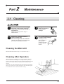
2-1 Cleaning
Switch off the machine and unplug
the power cord from the electrical
outlet before performing cleaning or
maintenance.
When you're finished,
wash your hands to
rinse away all
cuttings.
Failure to do so may result in injury or
electrical shock.
Please use a vacuum cleaner to
remove cutting dust.
Do not use any blower like airbrush.
Otherwise, dust spread in the air may harm
your health or damage this machine.
Use a commercially available brush
to remove metal cuttings.
Attempting to use a
vacuum cleaner to
take up metal
cuttings may cause
fire in the vacuum
cleaner.
Cleaning the Main Unit
When the main unit becomes dirty, use a dry cloth to wipe it.
Cleaning After Operation
After cutting work is completed, use a vacuum cleaner to clean the
main unit and the surrounding area of cutting dust. Be especially
careful to remove the cutting waste from around the pleated part of the
bellows cover and the connectors and terminals on the side of the
machine.
If necessary, move the T-slot table to the front and rear, and clean the
entire cover. In this case, switch on the power only when moving the
T-slot table then switch it off and continue cleaning.
49
Part 2 Maintenance
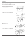
Cleaning with the Base Cover Open
If you’re using the safety cover (ZBX-650/500A), you must detach the front part of the safety cover in advance. For information on how
to detach the cover, refer to the “ZBX-650/500A Safety Cover User’s Manual.”
1
Switch on the power, move the table as far as it will go to
the rear, then switch off the power and unplug the power
cord from the electrical outlet.
2
Remove the screws at the four places at the front and rear
of the base cover.
Front
Rear
3
While lifting up the front part of the base cover, pull it
back toward you to remove it.
4
Use a vacuum cleaner to clean away any adhering cutting
waste near the Y axis.
50
Part 2 Maintenance
Cleaning Inside the Bellows Cover
As shown in the figure, pull out the bellows cover and use a
vacuum cleaner to clean away any adhering cutting waste near the
X axis or Z axis.
Near the X axis
* When moving the head, switch on the power and use the
control keys to move. After moving the head, be sure to
switch off the power and unplug the power cord from the
electrical outlet, and carry out cleaning.
Bellows cover
Near the Z axis
Bellows cover
Cleaning the Sponge in the Fan-motor Area (MDX-500 Only)
Remove the filter cover, then clean away any built-up grime on the
sponge inside.
* Install the filter cover with the convex surface facing upward.
If installed upside-down, it may become impossible to detach.
Filter cover
Sponge
51
Part 2 Maintenance
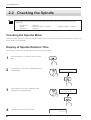
2-2 Checking the Spindle
A general guide to the service life of the spindle portion is shown below. We recommend prompt inspection and
replacement.
-Spindle motor:
-Spindle:
-Spindle belt:
8000 hours
High-torque spindle.....5000 hours
1500 hours
High speed spindle.....1500 hours
Checking the Spindle Motor
Operate the spindle motor alone, with no tool installed or material loaded. If the rotation speed is uneven or marked noise is produced, be
sure to contact a service technician.
Display of Spindle Rotation Time
The machine has a function for the displaying the total rotation time of the spindle.
1
Press the [EXIT] key several times to display the main
menu.
2
Turn the dial to move the arrow to [OTHERS], then press
the [ENTER] key.
3
Turn the dial to move the arrow to [REVOLUTION
TIME], then press the [ENTER] key.
4
Check the total rotation time of the spindle.
52
>10 OTHERS
11 To Coordinate
10>5 REVOLUTION TIME
6 To Main MENU
10-5 REVOLUTION TIME
125 Hour
Part 2 Maintenance
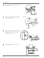
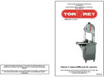
Adjusting the Tension of the Spindle Belt
This adjustment is required only for the belt for the high-torque spindle (ZS-650T/ZS-500T). We recommend checking it after approximately every 1,000 hours of working time.
First check the tension of the spindle belt. If this shows that the tension is outside the reference value, then adjust the tension.
Two special tools, a tension gauge (ST-001) and a tension adjuster (ST-040), are required to check the tension. These tools are sold
separately as service parts. Contact your authorized Roland DG Corp. dealer or service center.
1
Remove the screws shown in the figure and detach the
spindle motor cover.
(This requires a commercially available flathead screwdriver.)
MDX-650A/650
Spindle motor
cover
MDX-500
Spindle motor
cover
2
Loosen each of the four screws securing the spindle
motor one half-turn.
(This requires a commercially available hexagonal
wrench [size: 4 mm]. Use a tool with a ball-bit shape or
ordinary shape and measuring at least 100 mm in length.)
Loosen these screws.
Continued on the next page
53
Part 2 Maintenance
3
Set the tension adjuster (ST-040) in place at the location
shown in the figure.
4
Press with the tension gauge (ST-001) until the tension
adjuster (ST-040) touches the motor pulley, and the read
the value on the tension gauge.
TENSION ADJUSTER
(ST-040)
Top view
Motor pulley
Spindle pulley
Spindle belt
Tension adjuster
(ST-040)
Tension gauge
(ST-001)
5
Use the nut shown in the figure to reposition the spindle
motor so that the tension value is between 200 and 600 gf
(2.45 and 5.88 N).
(This requires a commercially available wrench or
hexagonal wrench [size: 5.5 mm].)
Left side
Spindle motor
6
54
Secure the spindle motor in place by tightening the
screws you loosened in step 2.
Tighten these screws.
Part 2 Maintenance
2-3 Lubricating the Ball Screw
When you're finished,
wash your hands to
rinse away all
cuttings.
Switch off the machine and unplug
the power cord from the electrical
outlet before performing cleaning or
maintenance.
Failure to do so may result in injury or
electrical shock.
Please use a vacuum cleaner to
remove cutting dust.
Do not use any blower like airbrush.
Use a commercially available brush
to remove metal cuttings.
Attempting to use a
vacuum cleaner to
take up metal
cuttings may cause
fire in the vacuum
cleaner.
Otherwise, dust spread in the air may harm
your health or damage this machine.
To keep using your machine in normal working order, lubricate the ball screw after approximately every 1,000 hours of working time.
Use Shell Alvania No. 0 grease.
X axis, Z axis
As shown in the figure, pull out the bellows cover and apply
grease directly to the ball screw. Apply grease to the entire screw
shaft, moving the head to expose ungreased areas.
Finally, move the head a full stroke in the X-axis or Z-axis
direction and wipe away excess grease.
X axis
Ball screw (X)
* When moving the head, switch on the power and use the
control keys to move. When you do this, return the pulledout bellows cover to its original position.
After you move the head, be sure to switch off the power
and unplug the power cord from the electrical outlet before
performing lubrication.
Bellows cover
Z axis
Ball screw (Z)
Bellows cover
55
Part 2 Maintenance
Y axis
1
Refer to "2-1 Cleaning__Cleaning with the Base Cover
Open" and detach the base cover.
Base cover
2
Apply grease directly to the ball screw. Apply grease to
the entire screw shaft, moving the head to expose
ungreased areas.
Finally, move the head a full stroke in the Y-axis direction
and wipe away excess grease.
Ball screw (Y)
* When moving the head, switch on the power and
use the control keys to move.
After you move the head, be sure to switch off the
power and unplug the power cord from the electrical outlet before performing lubrication.
We recommend also cleaning away any buildup of cutting waste near the X, Y, and Z axes at the same time that you
perform lubrication. (In "2-1 Cleaning," refer to "Cleaning with the Base Cover Open" and "Cleaning Inside the
Bellows Cover.")
56
Part 3
Appendix
3-1 The ZA-600/500 Series Spacer for the T-slot Table (Optional)
Checking the Accessories
Hexagonal wrench
Screws: 6
Spacers: 2
Installation
1
Switch on the power, then press the [
table as far as it will go to the front.
2
Turn the power OFF and unplug the power cord from the
electrical outlet.
] key to move the
57
Part 3 Appendix
3
Use the hexagonal wrench included with the spacers to
remove the screws at the six places shown in the figure,
then detach the T-slot table.
* Do not throw away the screws. Screws are
required when T-slot table is used without spacers.
4
Align the pins on the spacers with the pin-holes on the
slider, then place the spacers on the left and right.
Spacers
Pin
Slider
5
Align the T-slot table removed in step 3 with the pin-holes
on the spacers and set into place.
T-slot table
Pin
Pin
Spacer
Spacer
6
58
Secure in place at six locations with the screws included
with the spacers.
Part 3 Appendix
3-2 Main Optional Items
Unless stated otherwise, options for the MDX-650 can also be used with the MDX-650A. If the documentation does not list the MDX650A, follow the instructions for the MDX-650.
Spindle Area
Collet
Cutting Tool
Vacuum adapter
High-torque Spindle
ø6 mm
ø6 mm
*ZAD-500T
*ZS-650T
(For the MDX-650A/650)
*ZS-500T
(For the MDX-500)
Standardly included with the spindle
End mill
ø10, ø8, ø6.35, ø5, ø4, ø3.2, ø3 mm
*ZC-500T (Collet set)
ø10, ø8, ø6.35, ø5, ø4, ø3.2, ø3 mm
End mill
ø6.35, ø4.36 mm
*ZC-500TE (Collet and holder set)
ø6.35, ø4.36 mm
Engraving cutter
(ZS-500T only)
High-speed Spindle
*ZS-500SH
ø4.36 mm
ø4.36 mm
Standardly included with the spindle
Engraving cutter
ø6, ø5, ø4, ø3 mm
*ZC-23 (Collet set)
ø6, ø5, ø4, ø3 mm
End mill
ø6.35 mm
*ZC-23-6.35
ø6.35 mm
*ZAD-500S
End mill
Others
Spacer for the T-slot table
*ZA-503
3 cm (1-3/16 in.)
*ZA-505
5 cm (1-15/16 in.)
*ZA-508
8 cm (3-1/8 in.)
*ZA-613
13 cm (5-1/8 in.)
Center Vise
*ZV-500C
Vacuum Table
*ZV-500A
Safety Cover
*ZBX-650
for the MDX-650A/650 (Weight: 68 kg (149.9 lb.))
*ZBX-500A
for the MDX-500 (Weight: 53 kg (116.8 lb.))
* Indicates option part number. For tool part numbers, see the supply-part catalog.
59
Part 3 Appendix
3-3 Specifications
MDX-650A/650 Main Unit
MDX-650A/650
T-slot (XY) table size
Max. cuttng area
700 mm x 480 mm (27-1/2 x 18-7/8 in.)
650 mm(X) x 450 mm(Y) x 155 mm(Z) ( 25-9/16(X) x 17-11/16(Y) x 6-1/16(Z) in.)
XYZ motor
AC servo motor
Feed rate
X, Y, Z-axis: Max. 85 mm/sec. (3-3/8 in./sec.)
Acceleration
Software resolution
0.3G, 0.1G, 0.05G
[When RML-1 has been selected]
0.01 mm/step (0.00039 in.)
[When NC codes has been selected]
0.001 mm/step (0.000039 in.)
Note that the measurement unit for positioning coordinates is 0.01 mm/step (0.00039 in.).
Mechanical resolution
Spindle motor
Revolution speed
0.001 mm/step
DC brushless motor Max. 400W (when with high-torque spindle)
[High torque spindle]
3000 to 12000 rpm
[High speed spindle]
5000 to 20000 rpm
(Variable manually or by the command set)
Tool chuck
Positioning accuracy
Repeat accuracy
Collet or Cutter holder system
±0.1 mm (0.00394 in.) / 300 mm (11-13/16 in.)
(Under no-load conditions)
±0.05 mm (0.00197 in.) (Under no-load conditions)
Origin-point reproducibility
±0.08 mm (0.00315 in.)
(when the power is switched on/off)
Possible table load weight
Interface
[0.3G] 12 kg (26.5 lb.) or less
[0.05G] 20 kg (44.1 lb.) or less
Parallel (in compliance with the specification of Centronics)
Serial (under RS-232C standard)
Buffer size
2 Mbyte
( Replot buffer: [RML-1] 2 Mbyte [NC codes] Max. 2 Mbyte (end-user setting) )
Instruction system
Control keys
RML-1 (mode1, mode2) or NC codes supported by the MDX-650A/650 (Selectable through display operation)
COPY, XY/A, Z, +Z(Tool up), -Z(Tool down), PAUSE, SPINDLE,
,
,
,
, FAST FEED, JOG
EXIT, ENTER, Dial, EMERGENCY STOP switch
Power consumption
Dimensions
6.5 A / 117 V
120 kg (264.5 lb.)
1060 mm(W) x 1260 mm(D) x 1090 mm(H) (41-3/4(W) x 49-5/8(D) x 42-15/16(H) in.)
Packed weight
160 Kg (352.7 lb.)
Operation temperature
5 to 40°C (41 to 104°F)
Operation humidity
Accessories
3.5 A / 230 to 240 V
930 mm(W) x 1085 mm(D) x 870 mm(H) ( 36-5/8(W) x 42-3/4(D) x 34-5/16(H) in.)
Weight
Packed dimensions
3.5 A / 220 to 230 V
35 to 80% (no condensation)
T-slot clamps, Bolts (5 x 25 mm), Spanner (10 mm(3/8 in.)), Z0position sensor, Power cord, Belt for high-torque
spindle, Key connector, CD-ROM, Hexagonal wrench, Ferrite core, User's manuals
MDX-650A: Model compatible with the rotary axis unit and ATC unit
MDX-650: Model compatible with the rotary axis unit
60
Part 3 Appendix
MDX-500 Main Unit
MDX-500
T-slot (XY) table size
Max. cuttng area
550 mm x 360 mm (21-5/8 x 14-1/8 in.)
500 mm(X) x 330 mm(Y) x 105 mm(Z) ( 19-5/8(X) x 12-15/16(Y) x 4-1/8(Z) in.)
XYZ motor
AC servo motor
Feed rate
X, Y, Z-axis: Max. 85 mm/sec. (3-3/8 in./sec.)
Acceleration
Software resolution
0.3G, 0.1G, 0.05G
[When RML-1 has been selected]
0.01 mm/step (0.00039 in.)
[When NC codes has been selected]
0.001 mm/step (0.000039 in.)
Note that the measurement unit for positioning coordinates is 0.01 mm/step (0.00039 in.).
Mechanical resolution
Spindle motor
Revolution speed
0.001 mm/step
DC brushless motor Max. 400W (when with high-torque spindle)
[High torque spindle]
3000 to 12000 rpm
[High speed spindle]
5000 to 20000 rpm
(Variable manually or by the command set)
Tool chuck
Positioning accuracy
Repeat accuracy
Collet or Cutter holder system
±0.1 mm (0.00394 in.) / 300 mm (11-13/16 in.)
(Under no-load conditions)
±0.05 mm (0.00197 in.) (Under no-load conditions)
Origin-point reproducibility
±0.08 mm (0.00315 in.)
(when the power is switched on/off)
Possible table load weight
Interface
[0.3G] 12 kg (26.5 lb.) or less
[0.05G] 15 kg (33.1 lb.) or less
Parallel (in compliance with the specification of Centronics)
Serial (under RS-232C standard)
Buffer size
2 Mbyte
( Replot buffer: [RML-1] 2 Mbyte [NC codes] Max. 2 Mbyte (end-user setting) )
Instruction system
Control keys
RML-1 (mode1, mode2) or NC codes supported by the MDX-500 (Selectable through display operation)
COPY, XY, Z, +Z(Tool up), -Z(Tool down), PAUSE, SPINDLE,
,
,
,
, FAST FEED, JOG
EXIT, ENTER, Dial, EMERGENCY STOP switch
Power consumption
Dimensions
Weight
Packed dimensions
Packed weight
Operation temperature
Operation humidity
Accessories
6.5 A / 117 V
3.5 A / 220 to 230 V
3.5 A / 230 to 240 V
742 mm(W) x 843 mm(D) x 713 mm(H) (29-1/4(W) x 33-1/4(D) x 28-1/8(H) in.)
92 kg (202.8 lb.)
900 mm(W) x 970 mm(D) x 930 mm(H) (35-7/16(W) x 38-1/4(D) x 36-5/8(H) in.)
117 Kg (257.9 lb.)
5 to 40°C (41 to 104°F)
35 to 80% (no condensation)
T-slot clamps, Bolts (5 x 25 mm), Spanner (10 mm(3/8 in.)), Z0position sensor, Belt for high-torque spindle, Key
connector, Hexagonal wrench, User's manuals, CD-ROM, Power cord
61
Part 3 Appendix
Interface specifications
Parallel
Standard
In compliance with the specification of Centronics
Input signal
STROBE (1 BIT), DATE (8 BITE)
Output signal
BUSY (1 BITE), ACK (1 BIT)
Level of input/output signals
TTL level
Transmission method
Asynchronous
Serial
Standard
RS-232C specification
Transmission method
Asynchronous, duplex data transmission
Transmission speed
4800, 9600, 19200, 38400 (Selected using panel keys.)
Parity check
Odd, Even, None (Selected using panel keys.)
Data bits
7 or 8 bits (Selected using panel keys.)
Stop bits
1 or 2 bits (Selected using panel keys.)
Parallel connector (in compliance with
specifications of Centronics)
Signal
number
Terminal
number
Signal
number
NC
36
18
HIGH**
HIGH*
35
17
GND
Pin Connection
Serial connector (RS-232C)
Signal
number
Terminal
number
Signal
number
25
13
NC
24
12
NC
23
11
NC
1
18
NC
34
16
GND
GND
33
15
NC
22
10
NC
HIGH*
32
14
NC
21
9
NC
NC
31
13
HIGH*
20
8
NC
30
12
GND
19
7
SG
29
11
BUSY
18
6
DSR
28
10
ACK
17
5
CTS
27
9
D7
16
4
RTS
15
3
RXD
14
2
TXD
26
8
NC
36
19
DTR
NC
+5 V
D6
3.3K
GND
62
25
7
D5
24
6
D4
23
5
D3
22
4
D2
21
3
D1
20
2
D0
19
1
STROBE
*=
+5 V
** =
Pin Connection
100
1
13
1
25
14
Part 3 Appendix
About the Expansion connector
EXT.2
1 pin
2 pin
Compatible plug
Extension port
Use only a triple-contact plug of the size
described above.
This circuit is activated when the spindle motor is in operation.
NOTICE
NOTICE
Do not use terminal (3).
Use only terminals (1) and
(2).
Use within the rated range shown above.
Do not apply voltage greater than 25 V to
the terminal.
Do not short the terminal to ground.
No responsible is assumed for effects to which any equipment connected to this external output connector is subjected.
EXT.1, EXT.3 and EXT.4
The EXT.1, EXT.3 and EXT.4 (expansion connectors) are provided for expansion use by Roland DG Corp. Their specifications are
proprietary.
Roland DG Corp. assumes no responsibility for any effect on equipment due to the use of this port by the user.
63
Part 3 Appendix
MDX-650A/650 Dimensional Drawing
*Unit: mm
64
Part 3 Appendix
65
Part 3 Appendix
MDX-500 Dimensional Drawing
*Unit: mm
66
Part 3 Appendix
67
68
Please read this agreement carefully before opening the sealed
package or the sealed disk package
Opening the sealed package or sealed disk package implies your acceptance of the terms and conditions of this agreement.
Roland License Agreement
Roland DG Corporation ("Roland") grants you a non-assignable and non-exclusive right to use the COMPUTER
PROGRAMS in this package ("Software") under this agreement with the following terms and conditions.
1. Coming into Force
This agreement comes into force when you purchase and open the sealed package
or sealed disk package.
The effective date of this agreement is the date when you open the sealed package
or sealed disk package.
2. Property
Copyright and property of this Software, logo, name, manual and all literature
for this Software belong to Roland and its licenser.
The followings are prohibited :
(1) Unauthorized copying the Software or any of its support file, program module
or literature.
(2) Reverse engineering, disassembling, decompiling or any other attempt to
discover the source code of the Software.
3. Bounds of License
Roland does not grant you to sub-license, rent, assign or transfer the right granted
under this agreement nor the Software itself (including the accompanying items)
to any third party.
You may not provide use of the Software through time-sharing service and/or
network system to any third party who is not individually licensed to use this
Software.
You may use the Software by one person with using a single computer in which
the Software is installed.
4. Reproduction
You may make one copy of the Software only for back-up purpose. The property
of the copied Software belongs to Roland.
You may install the Software into the hard disk of a single computer.
5. Cancellation
Roland retains the right to terminate this agreement without notice immediately
when any of followings occurs :
(1) When you violate any article of this agreement.
(2) When you make any serious breach of faith regarding this agreement.
6. Limitations on Liability
Roland may change the specifications of this Software or its material without
notice.
Roland shall not be liable for any damage that may caused by the use of the
Software or by exercise of the right licensed by this agreement.
7. Governing Law
This agreement is governed by the laws of Japan, and the parties shall submit to
the exclusive jurisdiction of the Japanese Court.
R5-030109