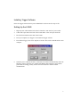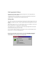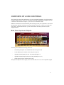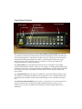
1
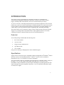
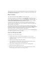
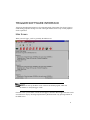
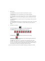
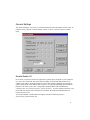
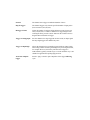
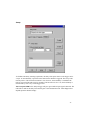
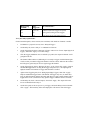
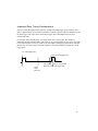
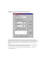
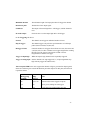
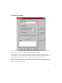
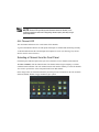
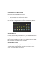
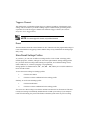
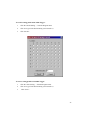
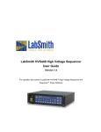
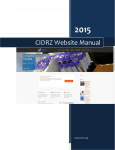
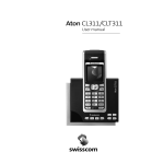
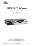
LC880 Experiment Controller
User Guide
Documentation for the LC880™ Controller
and Trigger™ Control Software v. 5.0
Trigger software ©1996--2008 LabSmith.
This manual ©2008 LabSmith. No part of this document may be reproduced or distributed without the consent
of LabSmith.
TABLE OF CONTENTS
INTRODUCTION
Parts List
Specifications
Basic Functions
How You Will Use the LC880
Installing Trigger Software
Setting Up the LC880
Field Upgradeable Software
Getting Help
OVERVIEW OF LC880 CONTROLS
Back Panel Inputs and Outputs
Front Panel Controls
TRIGGER SOFTWARE INTERFACE
Main Screen
General Settings
Disable/Enable I/O
Lock/Unlock Panel
Time base settings
5
5
5
6
6
7
7
8
8
9
9
10
11
11
13
13
14
14
CHANNEL PROPERTIES
15
Channel Properties Screen
Quiescent States
Logic
15
16
17
Logic Assignments
18
3
Parsing
Sending Logic
Experimenting With Channel Logic
Rules for Logical Assignments
Predefined Variables
Global Variables
Timing Modes
“Apply” versus “Program All Channels”
Fixed Output Mode
Passive Mode (Output = Input)
Clocked Pulse Stream Mode
Delayed Pulse After Trigger Mode
Important Delay Timing Considerations
Counter/Timer Mode
Dynamically-Delayed Pulse Mode
Toggled Output Mode
Dynamic Delay Compensation Mode
RUNNING EXPERIMENTS
Storing and Recalling Experiment Files
Front Panel Controls and Indicators
Channel LEDs
ALL Channel LED
Selecting a Channel from the Front Panel
Performing a Front Panel Function
Enable/Disable ALL
Enable/Disable Channel
Trigger a Channel
Reset
Store/Recall Settings Profiles
GLOSSARY
19
19
20
21
21
23
24
25
26
27
28
30
35
39
41
46
47
50
50
50
50
52
52
53
53
53
54
54
54
56
INTRODUCTION
The LC880 is a fully programmable logic and timing controller for coordinating and
synchronizing lab equipment and physical experiments. LC880 provides clocks, counters,
triggers, and many other useful functions, with 10 ns resolution and 100 ps accuracy.
As you are well aware, controlling and synchronizing experimental equipment are often the most
tedious tasks you’ll face in the lab. Experimenters regularly build their own controls from scratch
or piece together systems from the limited offerings on the market. The LC880 simplifies your
control setup, so you can go about the business of gathering data, and making knowledge.
The LC880 consists of two components: Trigger software and the LC880 experiment controller.
Trigger lets you design and run experiments from a simple graphical interface. The LC880
controller provides the connections and control for your experimental devices.
Parts List
Your LC880 package should include the following items:
1.
the LC880 controller
2.
AC power cable
3.
Trigger software installation CD
4.
9-pin RS232 cable
5.
User’s manual.
If any parts are missing or damaged please contact LabSmith support.
Specifications
Trigger software will run on any PC-compatible computer running Microsoft® Windows® 2000 or
XP or later. Drivers for National Instruments’® LabView™ software are also available for
download. See http://www.labsmith.com for more information.
The LC880 includes eight TTL-compatible inputs and eight TTL-compatible outputs. Voltages in
the range 2.5–5 V are TTL “highs” and voltages in the range 0.0–0.2 V are TTL “lows.”
Intermediate voltages should not be present on inputs and outputs except during transitions. The
inputs and outputs are protected against connection to 115 VAC. When disconnected the inputs
are read as TTL “highs.”
5
The LC880 can be connected to/ disconnected from the PC at any time without damage to either
unit. This ability allows you to program to LC880 at your computer, then to take the unit to the
experiment area for stand-alone use.
Basic Functions
The LC880 provides eight functional channels, or internal signal paths.
At any time, each channel can be assigned one of eight timing modes. Timing modes include
clocks, counters, delayed triggers, etc. You can set various properties for each timing mode—for
example, the delay length on a Delayed Trigger. All modes are aligned to a precise, 100 MHz
internal clock or an external clock, allowing resolution down to 10 ns.
Each channel also includes logic settings which specify the conditions that will trigger the
channel. A channel can be triggered by any logical combination of signals from the eight inputs
and/or the outputs of other channels.
The timing properties and logic that you set up in Trigger can be transferred and stored in the
memory of the LC880. You can store up to 64 variations of these properties in settings profiles in
the LC880. You can then switch between settings profiles to switch experiments, compare
different timing scenarios, or simulate different real world conditions.
All settings and setting profiles for a particular experiment can be stored as an experiment file on
your computer. Experiment files bear a .trg extension.
How You Will Use the LC880
In most cases, you’ll use the LC880 as follows:
1.
Using the Trigger software, open an existing experiment file, or create a new file.
2.
In Trigger (or LabView), program the properties and logic for each channel and for the
experiment as a whole.
3.
Send the properties and logic to the LC880’s memory.
4.
Test your program by simulating triggers and examining the outputs using the LC880’s
channel LEDs and/or an oscilloscope or other diagnostic tool.
5.
Store variations of channel properties in one of the LC880’s 64 settings profiles.
6.
Plug your experimental equipment to the LC880.
7.
Run the experiment, using the LC880 by itself or leaving it tethered to the PC. Switch
between settings profiles to explore various timing conditions.
Installing Trigger Software
Insert the Trigger Software disk in your CD-ROM drive and execute the setup.exe file.
Setting Up the LC880
1.
Plug the power cable from the back of the LC880 into a 100–250 VAC power outlet.
2.
Connect the 9-pin cable to the back of the LC880 and to a free serial port on the PC.
3.
Press the Power button on the front of the LC880.
4.
From your computer, run Trigger.exe to launch the Trigger software.
5.
From within Trigger, select View>Options>Com Port. The Serial Communications screen
will open.
6.
Select the port to which the LC880 is connected. The LC880 will automatically detect the
baud rate, which is typically set to 38400. If the RS232 cable running to your LC880 is
greater than 30 m long, you may need to lower the baud rate to achieve reliable
communication.
7
Field Upgradeable Software
The firmware in the LC880 is field upgradeable, allowing access to new timing modes and
capabilities as they become available.
To upgrade the firmware, download the latest version from www.labsmith.com. Then choose
“Update Firmware” on the Program menu to load data from that file.
Getting Help
This guide is your main source for information on operating the LC880 and Trigger software. The
guide is also available in an Abobe® Acrobat® Portable Document Format (pdf) file for electronic
viewing.
While running Trigger, press F1 to view this document on-line. Or, press SHIFT-F1, then select a
button or menu option to view help topics for a particular feature.
The LabSmith web site (www.labsmith.com) also includes helpful applications notes and other
technical information to help you use the LC880.
If you are unable to find the information you need, please contact our technical support team at
(925) 292-5161, or e-mail us at [email protected].
If you need to contact support, please let us know your LC880 serial number (located on the
bottom of the unit) and .the version of software you are using. To determine the software
version number, select “About Trigger” from the Help menu.
OVERVIEW OF LC880 CONTROLS
The LC880 is the control unit and interface for your experimental equipment. You will program it
using the Trigger software. Once you’ve designed, tested and downloaded your program, you can
control the LC880 from the computer, or you can run it in stand-alone mode.
Indicators and controls on the LC880 front panel will help you run your experiments. You’ll learn
all about these functions in the Experimenting section later. For now, we’ll give you a short tour
of the inputs, outputs and controls so you can work with the unit while you learn to use the
Trigger software.
Back Panel Inputs and Outputs
Channel
Channel
Clock
110-220 VAC Input
RS232 PC
The back panel includes the following connectors:
-
an internally-fused jack for a standard 100–250 VAC power cord
-
a 9-pin RS232 jack to connect to the Com port of your PC
-
eight BNC channel input jacks (in1–in8), normally high (5 V)
-
eight BNC channel output jacks (outA–outH), normally low (0 V)
-
a BNC input jack for an external clock source.
The inputs and outputs will accept any device into that sends or receives TTL-compatible signals.
9
Front Panel Controls
Power Switch
Power LED
Channel LEDs
Function Buttons
Channel Buttons
The LC880 front panel controls begin with the Power button and Power LED in the upper left
corner. When you first press the Power button, the LED will flash green and red while the system
runs its initial diagnostics. It will then glow steadily: if it glows a steady green, the front panel is
unlocked and accepting button pushes; if it glows red, the front panel is locked (see Trigger
Software Interface: General Settings below). Even the power switch will be deactivated,
safeguarding against mis-setting or tampering.
The channel LEDs offer useful information about the state of each channel. A green light
typically indicates that the channel is ready to receive a trigger. A red light typically indicates that
the channel is in the process of triggering. When a channel indicator is off, the channel is disabled
(see Running Experiments: Enable/Disable Channels). More will be discussed in the Timing
modes section.
The All Channel LED shows the status for all channels. A green LED indicates that the LC880
will respond to external inputs and that the external outputs are active. A red LED indicates that
the LC880 will not respond to external inputs and that outputs are in a fixed and frozen logical
state.
The Channel and Function Buttons work as pairs—you will select one of each to perform any
function. In the base state, all buttons glow dimly, indicating that they’re ready for your
instruction. Once you press a channel or function button, only the available options will be
illuminated.
TRIGGER SOFTWARE INTERFACE
Trigger has been designed exclusively for setup and control of the LC880. You’ll use Trigger to
set the timing properties and logic for each of the eight channels and to set up overall properties
for the experiment.
Main Screen
When you run Trigger, you’ll be greeted by the Main screen:
NOTE: At start-up, the Main screen will show the default program, which sets
all channels to “delayed trigger” mode.
From this screen you’ll control or access all of Trigger’s functions. Most Trigger functions can be
accessed in two ways by selecting an option from a pull-down menu or by pressing a button on
the Main screen.
11
1.
Menu options:
The File menu lets you open, close and save experiment files (.trg files).
The Edit Menu lets you cut, copy and paste text as you edit your program.
The View menu lets you set up the Trigger interface. Choose to display or hide the tool
bars and status bar, select the font used in Trigger, and set up communications with the
LC880.
The Channel menu lets you open the screens for “General Settings” and for each of the
eight channels.
The Program menu includes options for communicating with the LC880. You can send
logic, send properties, reset all channels, or enable/ disable the LC880’s inputs and
outputs.
2.
The buttons are as follows:
The General Settings button
opens the General Settings screen.
The Channel buttons open the Settings screens for all channels.
The Program button
updates the LC880 with all current settings.
The Reset button
resets all channels of the LC880. Retriggering Counters and
delay settings will be reset as well.
The Main window panel shows a text summary of all of the settings in the current
experiment. This summary may be printed for review and documentation purposes. The
text is not freely editable and must be modified through the dialogs. Double-clicking on
selected parts of the summary opens the dialog needed to edit the text.
At any time, the LC880 control bar can be hidden or displayed by clicking View>LC880.
General Settings
The “General Settings” screen lets you control functions that affect all channels of the LC880. To
reach this screen, click the “General Settings” button, or choose “General” from the Channel
menu.
Disable/Enable I/O
On occasion you will need to abort an experiment or quickly place all outputs to your equipment
in a “safe” state. Each of the tabs of the General Settings screen includes buttons that let you
“disable” and “enable” all inputs and outputs to the LC880. With I/O disabled, input signals are
ignored. Each output will be held at either a logic low or logic high, depending upon its channel
properties. We’ll refer to the “safe” voltage that a channel produces when disabled as the
“quiescent state” (see Channel Properties: Quiescent States). To restore channels functions, click
the “Enable I/O” button. These functions are nonvolatile: the enabled and disabled states are
restored on power cycle.
You can also disable or enable inputs and outputs from the LC880 front panel (see
Experimenting: Disable/Enable All).
13
Lock/Unlock Panel
Lock or unlock the front panel buttons using the “Lock Panel” and “Unlock Panel” buttons. This
functionality is handy, for example, in an embedded control application where the LC880 should
function only in stand-alone or computer-controlled modes. When the panel is locked, the LED
next to the power button glows a steady red and all buttons are dark. When the panel is unlocked,
the power LED glows green and the front-panel buttons are illuminated.
Like the enable/disable I/O functions, these settings are nonvolatile and are restored on power up.
Because the power button is disabled, the LC880 must be disconnected from AC power to turn it
off, if the front panel is locked.
Time base settings
Each pair of channels of the LC880 can independently utilize one of four different time bases so
you can control and measure events which occur a few nanoseconds apart, or a few hundred
seconds apart.
In “100” MHz time base mode (the default), the LC880 aligns signals to an internal 100 MHz
clock, for timing resolution of 10 ns. Use this “high resolution” mode when the events of your
experiment occur in rapid succession (milliseconds or less).
“100/64” MHz time base mode allows the LC880 to control events that occur over longer time
periods (milliseconds to minutes). This is called “low resolution” mode in the following
documentation.
In “Ext.” time base mode, the channels use an external clock input for the time base. This input
must be TTL-level between 1 and 100 MHz applied to the External Clock (ext clk) input on the
back of the LC880. This function allows the use of high-precision or variable-frequency time
bases. It also allows multiple LC880s to be synchronized to the same base.
NOTE: The “External” time base cannot be produced by a channel that uses the
same time base as an input.
“Ext./64” time base mode divides the frequency of the signal applied to the external clock input
before using it as a time base. If the external clock is being used as a time base, the frequency
entered into the edit box is used to calculate the timing settings. If this setting is 10% higher than
actual, the channels using this time base will be 10% long on delays and duration.
CHANNEL PROPERTIES
Channel Properties Screen
Each channel has a Settings screen in which you’ll select the timing mode, set the timing
properties, and establish the logic that will determine when the channel will trigger.
To open the Settings screen for a channel, select the channel from the Channel menu, or click a
channel button (A–H) on the Main screen. You can open more than one channel screen at a time.
Channel properties are organized by tabs. The tabs that are relevant for a particular timing mode
appear automatically when that timing mode is selected. For convenience, all settings are retained
and saved, including those for timing modes that are not currently selected.
15
Four additional buttons appear next to the tabs:
-
Disable temporarily disables the channel. The channel remains fixed in its “quiescent
state” (see Quiescent States below). The front panel LED for that channel will be unlit
(See Running Experiments: Channel LEDs).
-
Enable restores channel functions following a temporary disable. The front panel LED
for that channel will glow to indicate the channel's status.
-
Reset reinitializes the internal trigger counters and sweep timing for the current channel.
This function can be called simultaneously for all channels by pressing the “Reset”
button on the main tool bar.
-
Force Trigger lets you simulate a valid input signal for the channel (see Channel
Properties: Logic for more). This button, which is only available with functions that can
be triggered, is useful both for troubleshooting your channel settings and implementing
software control of experiments. You can also force-trigger a channel from the LC880
front panel (See Running Experiments: Force Trigger).
Quiescent States
When you disable a channel, its input will not change the output. The “quiescent state” of a
channel is the setting of its output when the channel is disabled. You can set each channel’s
quiescent state to be a TTL high (3.5–5 V) or low (0–0.2 V) to provide a safe signal to the output
device if you need to abort an experiment or stops its progress.
The method for setting the quiescent state depends on the timing mode. Most modes include an
“Invert Output” option which sets the output normally High.
Logic
A channel can be triggered by any combination of signals from the eight inputs and/or other
channel outputs. Channel logic determines the combination of signals that triggers the channel.
The diagram below shows the architecture of the LC880. Note that any inputs and outputs can
trigger a channel without external cabling.
To define when a channel will trigger, open the channel’s Settings screen then click the “Logic”
tab. This tab only appears for timing modes which respond to logic. You will enter a logic
assignment for the channel in the large white box.
NOTE: Some timing modes do not respond to trigger logic. For example, a channel
set to operate as a clock will continue to run regardless of what happens to its input.
17
Logic Assignments
The logic processor assigns the combination of external inputs (in1–in8) and channel outputs
(outA–outG) that will trigger each channel. Logic assignments always appear in the following
format:
[the channel to be triggered] = [the conditions that will trigger it];
External inputs and channel outputs feed into the logic processors; therefore, they appear only on
the right side of assignments. Logic processor outputs feed the timing channel inputs inA–inH;
these terms appear only on the left side of assignments.
Here is an example:
inB = in2;
This assignment means, “Channel B will be TRUE when Input 2 goes TRUE (reaches ~ 5 V).”
The assignment:
inB = not in2;
means “Channel B will trigger when Input 2 goes FALSE (drops below 0.2 V).”
You can employ compound arguments in logical assignments, such as:
inB = not outC and in2;
This means, “Channel B will trigger when the output of Channel C is FALSE and Input 2 is
TRUE.”
This example is more complex still:
inB = (in1 or in2) and (outC or outD);
Here, Channel B requires a TRUE signal from Inputs 1 or 2, combined with a TRUE signal from
Channels C or D, in order to trigger.
NOTE: LC880 inputs are TRUE by default if nothing is connected (i.e., the input is
normally weakly pulled high). Grounding an input switches its state to a logical FALSE.
It is important to distinguish between the eight physical input jacks, in1–in8, and the eight timing
channel inputs. Any combination of the physical inputs can be used to trigger the channel inputs.
The following assignment is incorrect:
outA = in1;
because it attempts to trigger a channel output rather than a channel input, inA–inH
This assignment is also invalid:
in1 = in2;
because it attempts to assign a value to External Input 1.
Finally, this assignment is invalid:
inB = inA;
because it attempts to assign a value from one channel input to another.
Parsing
When you have completed a logical assignment, click the “Apply” button. Trigger will check your
syntax and logic and will report any mistakes to you by line number.
Sending Logic
If you change channel logic you must transfer those changes to the LC880 to implement them.
To transfer logic to the LC880, click the “Set All Channels” button
Program>Program All Channels.
, or choose
While the logic is transferring, the Power LED on the LC880 will turn red. This transfer typically
takes only a second, though it may take slightly longer for complex programs.
After the transfer, the logic settings reside in the LC880, even if you turn the unit off or
disconnect it from the PC.
19
Experimenting With Channel Logic
This brief example will show you more about channel logic:
1.
Connect a normally-open switch to Input 1 and another to Input 2.
2.
Connect an LED to Output A.
3.
Open the Channel Settings screen for Channel A.
4.
Choose “Output = Input” from the “Timing Mode” list. In this mode, the output of
Channel A is always the same as its input.
5.
Select the “Passive” tab and choose “Output = Input.”
6.
Select the “Logic” tab and enter:
inA = in1;
7.
Click the “Set All Channels” button.
The LED at Output A should be glowing, indicating that the output is TRUE, or HIGH (since
LC880 inputs are normally HIGH). When you close Switch 1, the LED will turn off,
indicating that the output is FALSE, or LOW.
NOTE: The Channel A LED on the front of the LC880 glows green while the channel
output is LOW, or red when the output is HIGH. But don’t be confused! The channel LED
does not always indicate the channel’s output state—only in certain Timing Modes. You’ll
learn more later in the Timing Modes section.
8.
Next, change the logic assignment to:
inA = not in1;
9.
Click the “Set All Channels” button. The LED at Output A will now remain off until you
close the switch.
10. Change the logic assignment to:
inA = not in2;
11. Click the “Set All Channels” button. The LED at Output A will now remain off until you
close Switch 2.
12. Lastly, change the logic assignment to:
inA = not in1 and not in2;
13. Click the “Set All Channels” button. The LED at Output A will remain off until both
switches are closed.
Rules for Logical Assignments
The following rules apply to logical assignments:
-
Logic is case-sensitive. Use lowercase and capital letters as in the samples above.
-
Spaces matter. Use spaces per the samples above.
-
If a logical assignment consists of more than one line, each line should end in a carriage
return.
-
The last line of a assignment must end in a semicolon.
-
You can add comments to annotate your logic assignments. Single line comments begin
with //. Multi-line comments begin with /* and end with */.
-
Many symbols can be written using C-Style programming commands. For example, “not
in1” can be written “!in1”.
The following symbols can be used in logical assignments:
Symbol
Shorthand
not
!
and
&
or
| (vertical line)
xor
#
HIGH
none
LOW
none
()
none
;
none
Predefined Variables
Trigger includes a number of Predefined variables to speed logic coding. To view the variable
names that are recognized by Trigger, click “Predefines” on the “Logic” tab.
21
-
inA–inH: the input of channels A through H. These signals only appear internally at the
input of the timing channel; they are not connected to the rear BNCs. These symbols can
only be on the left-hand side of an assignment
-
in1–in8: inputs 1 through 8 from the rear BNC connectors.
-
outA–outG: outputs of channels A through G that appear at the rear BNC connectors.
NOTE: The output of channel H is not internally connected to the logic processor. It
cannot be used in logic assignments unless it is externally connected to another channel
input.
-
LOW, FALSE: trigger input always low.
-
HIGH, TRUE: trigger input always high.
Double click a variable to copy it to your Logic assignment. You can also select the variable then
click “OK.”
Global Variables
“Local Variables” are those that are used directly in logic assignments, such as “inA” or “out1.”
Logical assignments that are used repeatedly in your experiment can be stored as “global
variables.” With global variables, complex logic is easier to read and debug.
Several channels in your experiment may need to be triggered by the same event. For example,
Channels F, G and H must trigger when:
(in1 or in2) and (outC or outD).
Rather than typing that logic each time, you may define it as a variable:
event1 = (in1 or in2) and (outC or outD);
Now you can use “event1” in the logic for Channels F, G and H:
inF = event1;
To view the global variables, click the “Globals” button on the “Logic” tab. The “Globals”
screen will open:
23
To create a new global variable, type the variable’s name followed by its definition. In this
example we’ve defined variables named “arm” and “fire.” Be sure to end your definition with a
semicolon. Click “Apply” to save the variable.
Timing Modes
In the previous section you learned that logic defines how channels are triggered. In this section
you’ll use the LC880 timing modes to determine how the channels will respond.
Each channel can be configured to operate in one of eight modes:
-
Fixed output
-
Output=Input (Passive Mode)
-
Delayed Pulse After Trigger
-
Clocked Pulse Stream
-
Validated Trigger Input (Noise Suppression)
-
Dynamically Delayed Pulse
-
Counter/Timer
-
Toggled Output.
When a timing mode is selected, the relevant property tabs will be displayed.
NOTE: All timing property tabs include a space for Notes. These notes are saved and
appear in the Main Screen program summary area. It is good practice to document your
settings extensively. As with all programming, good documentation will simplify the process
of creating, debugging and running your experiments.
For each timing mode you’ll be able to set up a simple example to view the output of the channel.
To set up for the experiments later in this section:
1.
Make sure that the LC880 is connected to the PC.
2.
Plug a normally open push-button trigger switch into Input 1. The button will represent our
triggering “event.”
3.
Open Channel A’s Setting screen, and select the “Delayed pulse after trigger” timing mode
(you’ll learn about Delayed Trigger mode shortly).
4.
Select the “Logic” tab. Enter the logical assignment:
inA = not in1;
Then click OK. With this logic, Channel A will trigger when you depress the trigger
button.
5.
Now transfer the logic to the LC880 by clicking the “Set All Channels” button
6.
Plug an oscilloscope to Output A to observe the channel output. Remember, the output
voltage will vary from 0 to 5 V.
.
“Apply” versus “Program All Channels”
Each properties screen includes an “Apply” button which, when clicked, will send the current
timing properties to the channel on the LC880.
NOTE: If you change a channel’s properties, closing the Settings screen will have the
same effect as clicking “Apply.” Clicking the “OK” button will also have the same effect.
Logic settings are sent and saved in the LC880, but any changes are not implemented on the
LC880 until you click “Set All Channels” button
Program>Program All Channels.
on the Main screen or choose
“Program All Channels” is the same as clicking “Apply” for all channels and then instructing the
LC880 to update its logic programming.
The “Cancel” button cancels any edits made since the last time the “Apply” button was clicked
and closes the dialog window.
25
Fixed Output Mode
In this mode, the channel output remains in the selected state (Low or High), regardless of the
input.
The front panel LED for the channel will glow green when the output is low or red when the
output is high.
To try fixed output mode:
On the “Properties” tab of Channel A, choose “Fixed Output” from the pop-up. Choose “Low” or
“High” as the output state, then click “Apply” to save the settings. At Output A, the signal will
remain a steady TTL logic low or high, depending on your selection.
Passive Mode (Output = Input)
In passive mode, the output signal equals the input signal or its logical inverse.
The front panel LED for the channel will glow green when the output is Low or red when the
output is high.
To try passive mode: On Channel A’s Settings screen, select the “Output=Input” timing mode. In
the Function box, choose “Output=Input,” then Click “Apply” to save the settings.
When the trigger button is not depressed (i.e., the input signal is low), the signal at Output A will
be a TTL low. Now, depress the trigger button at Input 1—the signal at Output A will go high. If
you select “Output=!Input (invert), the channel output will remain high until you depress the
trigger.
27
Clocked Pulse Stream Mode
In clock mode, the output of the channel is a steady stream of pulses. You set the pulse duration
and delay between pulses. A clock channel’s input does not affect its output.
The front panel LED for a clock channel will glow green when the output is low or red when the
output is high.
NOTE: For a high-frequency clock the LED will alternate between red and green so
quickly that it will appear as a continuous pale green, yellow or orange light.
As mentioned earlier, the LC880 can operate in two internal clock modes: “100” MHz highresolution and “100/64” MHz low-resolution (see General Settings: Time Base Settings). In high
resolution mode, the clock pulse and duration can range from 0.48 µs to 52.4 ms. In low
resolution mode, pulse and duration can range from 30.1 µs to 3.35 s.
To set the duration of the high state, select the timing units (seconds, microseconds, milliseconds
or nanoseconds) from the pop-up, then enter a duration in the “Clock high duration” box.
To set the duration of the low state, select the units, then enter the duration in the “Clock low
duration” box.
A clock’s quiescent state is normally low (See Channel Properties: Quiescent States). Check the
“Inverted output” box if the quiescent state for the channel should be high instead.
To try Clock mode:
1.
On the General Settings screen, select “100/64” (low resolution mode) for Channels A
and B.
2.
On Channel A’s Properties tab, choose “Clock” as the mode, select an “on” duration of
100 ms and an “off” duration of 500 ms. Click “Apply” to save the settings.
The signal at Output A will go high every 500 ms and will remain high for 100 ms each time.
To test faster clock settings, select “100” (high resolution) mode under General Settings, then set
duration and delay times of less than 52 ms.
29
Delayed Pulse After Trigger Mode
Upon receiving an input signal, a delayed trigger waits a specified delay time, then sends a pulse
to the channel output. This mode has several property tabs.
Delay
On the Delay tab you’ll specify:
Delay after trigger
The delay between a valid trigger and an output signal
Duration of pulse
The duration of the output signal
Until Reset
The output will remain high after a valid trigger, until the channel is reset
Inverted Output
Check the box to set the output high until a valid trigger.
The range of settings you can use with the delayed trigger depend upon the current timing mode:
Delay range
Duration range
Delay / Duration
resolution
100 (high res mode)
20 ns to 21.47 s
7.7 µs to 21.47 s.
10 ns
100/64 (low res mode)
1.28 µs to 1374 s
493 µs to 1374 s
640 ns
Triggering
This tab lets you control how the channel will trigger:
31
Normal
The channel can retrigger an unlimited number of times
Skip N triggers
The channel triggers only after the specified number of input pulses
(between 0 and 2,147,483,647).
Retrigger N times
Limits the number of retriggers allowed between resets (between 0
and 2,147,483,647). To allow a channel to be triggered again after
reaching the limit, press the “Reset” button on the LC880 or choose
Program>Reset Channels in Trigger.
Trigger on rising input
Sets the channel to be edge triggered. In other words, an input signal
that stays high triggers the channel only once.
Trigger on input high
Allows the channel to be repeatedly triggered while an input is high.
This setting could be used for generating a low-precision gated clock,
for example. However, the latency time between retriggers is
indeterminate (typically around 10 µs) so a clock made this way is not
suitable for applications requiring high precision.
Alert host computer
trigger
Sends a “ping” to the PC upon completion of the trigger following
cycle.
Sweep
To facilitate time-delay scanning experiments, the delay of the pulse relative to the trigger can be
“swept” or incremented by a specified value each time the channel is triggered. The sweep value
must be positive. The increment resolution is 5 ns. However, the actual delay is rounded to the
nearest 10 ns at full internal clock. For example if the increment is set to 5 ns, the actual delay is
incremented by 10 ns every second trigger event.
The front panel LED for the delayed trigger will glow green until an input signal is detected. The
LED will be unlit for the delay time and will glow red for the duration time. What happens next
depends upon the channel settings:
33
Retriggering
enabled?
Edge
triggered?
The channel LED…
no
yes or no
remains red (no more triggers accepted)
yes
no
glows green (waiting for next trigger)
yes
yes
is off; glows green once input goes low.
To try the delayed pulse mode:
Under General Properties, choose 100/64 (low resolution) clock mode for Channels A and B.
1.
In Channel A’s properties screen, select “Delayed Trigger.”
2.
On the Delay tab, enter a delay of 1 s and duration of 500 ms.
3.
On the Triggering tab choose “Retrigger N Times” and set N=0. Choose “Input high (level
trigger),” then click “Apply” to save the settings.
4.
Click the trigger pushbutton. One second after you push it, the output of Channel A will
go high for 500 ms.
5.
The channel LED remains red, indicating it is not ready to trigger. Push the button again.
You’ll see that you cannot retrigger the channel. Click the “Reset” button on the LC880—
the LED glows green and you can once again trigger the channel.
6.
On the Triggering tab, choose “Retrigger N times,” set N=5, then click “Apply.” Depress
and hold the trigger button. As long as the trigger is depressed (i.e., the input signal is
high) the channel will continue to trigger until the limit is reached.
7.
Again on the Triggering tab, select “Rising Input (Edge Trigger)” then click “Apply.”
Depress and hold the trigger button. The channel will trigger only once, no matter how
long you hold the button. Release the button and depress it again, and the channel will be
triggered once more (switch bounce may produce triggers when the button is released).
8.
On the Delay tab, check “Inverted output,” then click “Apply.” The output will be the
inverse of that described in Step 4.
9.
On the Sweep tab, set the sweep to 0.5 s per trigger, and on the Delay tab select Normal.
Click “Apply.” The time delay before the output pulse will increase with each trigger.
Important Delay Timing Considerations
Once the LC880 has begun a delay sequence, it ignores incoming trigger pulses. There is also a
delay of approximately 10 μs after the completion of a delay sequence while the channel resets for
the next trigger. This effect can be used to skip triggers, but if misunderstood it can cause
unexpected results.
For example, in the diagram below, two trigger pulses arrive 100 μs apart. The channel is
functioning in Delayed Pulse Mode, with a delay of 50 μs and a duration of 45 μs pulse. It would:
receive the first pulse; wait 50 μs; send a 45 μs output pulse; and trigger again at the second pulse.
But the extra 10 μs delay at the end of the sequence will cause the channel to ignore the second
trigger pulse.
t=0 μs first trigger pulse
t=100 μs second trigger pulse
t=50 μs
output
pulse sent
t=95 μs delay t=105 μs channel ready
sequence ends for next trigger pulse
35
Validated Trigger Input Mode (Noise Suppression)
The noise suppression function eliminates false triggers due to noise on the input signal by
requiring the signal to remain high (or low) for a specified duration. If the signal drops out during
that period, the output will remain low and the channel will look for the next input signal. Once an
input signal is deemed “valid,” a pulse of user-specified duration will be sent to the channel
output.
Unlike an analog filter which “smears” the signal edge, this noise suppression function digitally
blocks false triggers, retaining the sharp edges on the real trigger signal.
As with Delayed Pulse After Trigger mode, you have additional controls over the channel.
On the Validate tab, choose:
Minimum duration
The minimum length of an input pulse that will trigger the channel
Duration of pulse
The duration of the output signal
Until Reset
The output will remain high after a valid trigger, until the channel is
reset
Inverted Output
Check the box to set the output high until a valid trigger.
On the Triggering tab choose:
Normal
The channel can retrigger an unlimited number of times
Skip N triggers
The channel triggers only after the specified number of valid input
pulses (between 0 and 2,147,483,647).
Retrigger N times
Limits the number of retriggers allowed between resets (between 0 and
2,147,483,647). To allow a channel to be triggered again after reaching
the limit, press the “Reset” button on the LC880 or choose
Program>Reset Channels in Trigger.
Trigger on input high
While the input is high, channel can be repeatedly triggered.
Trigger on rising input Sets the channel to be edge triggered (i.e., an input signal that stays
high will only trigger the channel once).
The front panel LED for the noise suppression channel will glow green until an input signal is
detected. It will then glow red until the duration period has elapsed. At this point, the LED will
respond as follows:
Retriggering
enabled?
Edge
trigger?
LED
no
yes or no
remains red (no more triggers accepted)
yes
no
glows green (waiting for next trigger)
yes
yes
is off; glows green when trigger goes low
37
To try validated trigger mode:
1.
On the General Settings screen, select 100/64 (low-resolution) mode for Channels A and
B.
2.
In Channel A’s properties, select “Validated Trigger Input” mode.
3.
On the Validate tab, enter a “Minimum duration” and “Duration of output pulse” of 1
second each.
4.
On the Triggering tab, select “Retrigger N times,” and set N=50. Click “Apply” to save
the settings.
5.
Now, depress the trigger button. If you hold the button down for more than one second
(the minimum duration), the output of Channel A will go high. If you release the button
before one second elapses, the output will remain low, and the channel will wait for
another input pulse.
Counter/Timer Mode
The counter/timer mode determines the time delay between two separate input signals and reports
it back to the PC. You can view the counter output in the Properties tab.
Use the channel’s logic to select the input signals that will be compared by the counter (see
Channel Properties: Logic above). For example, if the logic reads “in1 and in2;” the counter will
determine the time delay between a pulse at Input 1 and the next pulse from Input 2.
Normally, the counter will report a value each time a pair of pulses is measured. To retain the
current measurement, check the “Hold measurement” button; the counter will not update the delay
display until this button is cleared.
39
NOTE: To switch from counter mode, first click the Disable button and ensure the
channel LED is unlit, indicating that the channel is disabled. This will help you avoid
unexpected behaviors when the counter is transmitting measurements rapidly (e.g.,
>1000 measurements per second).
NOTE: When you first run the LC880, channels that are configured as counters are
initially disabled and must be enabled either by clicking the “Enable” button on the
channel’s Properties screen, or by using the front panel (See Experimenting:
Disable/Enable Channels below).
The front panel LED for the counter will be green until the first trigger, red until the second
trigger and off while the count data is reported and the channel waits for the input to return low.
The output of a channel in counter mode is always high.
To try the counter/timer mode:
One good way to see the counter in action is to have it compare the outputs of two clock channels.
The counter will measure the difference between the successive pulses of the two channels.
1.
On the General Settings, select Full (high resolution) clock mode.
Channels B and C will be our clocks. We’ll use odd delay and duration values for the clocks
so that the difference between pulses will be obvious.
2.
On Channel B’s properties tab, select Clock mode. Enter a delay of 54 ms and a duration of
79 ms. Click “Apply.”
3.
On Channel C’s properties tab, select Clock mode. Enter a delay of 87 ms and duration of 85
ms. Click “Apply.”
4.
On Channel A’s Logic tab, enter: inA = outB and outC; (You’ll learn more about channel
logic in the Logic section above).
5.
On Channel A’s Properties tab, select Counter mode, with milliseconds as the units. Click
“Apply.”
6.
Lastly, click “Send Logic” on the Main screen to update the new logic for Channel A.
The time difference measurements should now appear, in rapid succession, in the “Last Measured
Period” box on Channel A.
NOTE: The LC880 may be measuring time differences faster than it can display them
all on the monitor.
Now, check “Hold measurement.” Note that the displayed measurement does not change. Uncheck “Hold Measurement”, then check “Hold measurement” again to freeze another
measurement.
Dynamically-Delayed Pulse Mode
The dynamic delay is the LC880’s piece de resistance. First, it measures the time difference
between two pulses, like a counter. Next, it scales that difference by a user-defined factor. It
subtracts an offset value, waits the duration of the dynamically calculated delay, then sends a
pulse to the channel output.
NOTE: The dynamic delay is particularly useful for ballistics or gas dynamics
experiments, in which the velocity of a projectile or wave must be calculated and used to
time the triggering of an experimental device.
Dynamically Delayed Pulse mode includes several properties tabs.
41
Scaling
In the calculation of the delay, the measured delay between two pulses is scaled by a factor of 2N,
where –16 < N < 16, or N/16, where 0< N < 256. The former scaling is faster and a scaling of 1:1
is fastest. Scaling can typically be done at rates > 50 kHz.
The maximum delay between input pulses is 52 ms in hi-res mode (100 MHz) and 3.3 s in low-res
mode (100/64). The maximum delay resulting from the scaling and offset calculations is
respectively 21.47 s and 1374 s in hi-res and low-res modes. The delay must be positive.
Delay
Added Delay
Set an offset value to subtract from the scaled delay length. This is
useful when accounting for camera shutters or other lag times in
experimental equipment. The offset value can be positive (shortens
the delay time) or negative (lengthens the delay time) and the
resolution is set by the time base (e.g., 10 ns).
Duration of pulse
The duration of the output signal
Until Reset
The output will remain high after a trigger until the channel is reset
Inverted Output
Check to set the output high until a valid trigger. The duration of the
pulse and other properties are the same as for the delayed trigger.
43
Triggering
The triggering options are the same as those for Delayed Pulse After Triggering mode:
Normal
The channel can retrigger an unlimited number of times
Skip N triggers
The channel triggers only after the specified number of input pulses
(between 0 and 2,147,483,647).
Retrigger N times
Limits the number of retriggers allowed between resets (between 0
and 2,147,483,647). To allow a channel to be triggered again after
reaching the limit, press the “Reset” button on the LC880 or choose
Program>Reset Channels in Trigger.
Trigger on rising input
Sets the channel to be edge triggered. In other words, an input signal
that stays high triggers the channel only once.
Trigger on input high
This option is not used in this mode.
Alert host computer
following trigger
Sends a “ping” to the PC upon completion of the trigger cycle.
The front panel LED for a dynamically-delayed trigger will remain green until a valid input
signal is detected. When an input signal is detected, the LED will glow red until the output signal
is sent. At this point the LED will return to green if retriggering is allowed, or it will glow red to
indicate that no more input signals will be accepted.
To try the dynamically-delayed pulse mode:
You can simulate the experiment above, using the trigger button to represent Sensor 1, and a
delayed trigger in Channel B to represent the signal from Sensor 2. Connect your oscilloscope to
the Output C to view the results.
1.
On the General Settings screen, select 100/64 (low-resolution) mode for Channels C and D
(and optionally for Channels A and B).
2.
On Channel A’s Properties tab, select “Output=Input” mode.
3.
On Channel A’s Logic tab, enter: inA = not in1;
4.
On Channel B’s Properties window, select “Delayed Trigger” mode, with a delay and
duration of 100 ms each. Setup for edge triggering and allow retriggering.
5.
On Channel B’s Logic tab, enter: inB = outA; This logic will cause the delayed trigger to
pulse 100 ms after a signal from Channel A.
6.
On Channel C’s Properties window, select “Dynamically Delayed Pulse” mode. Set up for
scaling by 2N, where N = 1, and set the Added Delay to –200 μs and the duration to 100 ms.
Allow unlimited retriggering.
7.
Since you’ve made changes to multiple channels, go to the Main screen and click the “Set All
Channels” button. All of your changes will now be stored in the LC880.
Now the test is ready. Depress and hold the trigger button. Output A will transition high, causing
the delayed trigger in Channel B to begin its count. When Channel B sends its output pulse, the
dynamic delay in Channel C will calculate the time difference (100 ms), multiply it by 32/16, and
subtract the 200 µs offset. 199.8 ms after receiving the signal from Channel B, Channel C will
send a 100 ms output pulse.
45
Toggled Output Mode
This mode toggles its output state upon every input pulse. It functions like a flip-flop and is useful
for a variety of logical and control purposes. The minimum input-pulse state duration is 10 ns and
the edge-to-toggle delay is < 20 ns.
The only user settings for this mode are the initial state, which may be either low or high.
The front panel LED for the channel will glow green when the output is low or red when the
output is high.
Dynamic Delay Compensation Mode
Many electronically triggered devices exhibit significant drift due to temperature changes, time.
etc. This mode is designed to dynamically adjust trigger timing to compensate for drift in a laser
or other electronics.
To use the mode, you’ll enter the desired delay between the triggering of an event and the actual
occurrence of the event (say, the light emission from a laser). Two signals are then mapped
logically to the channel input: the trigger signal, and some indicator of the actual occurrence of the
event (say, a photodiode triggered by the laser light). The channel then measures the actual delay
between the trigger and response. It then adjusts the next trigger pulse accordingly to maintain the
desired delay to within approximately 10ns. To reduce jitter from shot-to-shot timing fluctuations
or noise you can determine the delay compensation by averaging over a series of trigger pulses
rather than adjusting for each individual trigger.
Dynamically Delay Compensation mode includes several properties tabs.
Delay
47
Desired delay
The delay between the trigger and response signals that Trigger will
attempt to maintain.
Duration of pulse
The duration of the output signal
Inverted Output
Check to set the output high until the next valid trigger.
Averaging
Delay Averaging
Determines how the delay compensation will be calculated. Choose
None to calculate a new delay compensation time with each trigger
pulse; or, choose to use an average compensation based on the last 2
to 256 trigger pulses. Averaging is performed with an infinite
impulse response filter (i.e., a conventional one-pole low pass filter).
The number of triggers sets the filter response time.
Sweep
The delay between the trigger and response can be “swept” or incremented by a specified value
each time the channel is triggered. The sweep value must be positive. The increment resolution is
5 ns. However, the actual delay is rounded to the nearest 10 ns at full internal clock. For example
if the increment is set to 5 ns, the actual delay is incremented by 10 ns every second trigger event.
To try the dynamically-delayed compensation mode:
In this example an external delay generator is used to simulate a laser with the Trigger In as the
laser trigger and the Delay Out as a signal from a photodiode monitoring the laser pulse. The
delay within the delay generator will changed from 0 to 10 µs, yet, regardless of this fluctuation,
the laser will continue to fire 25 µs after its trigger pulse.
Setup the LC880 as shown below:
Channel A:
Free-running clock: High duration: 10.000 us; low duration: 990.000 us.
Channel B:
Dynamic delay compensation: Adjust delay for 25.000 us between inputs.
Pulse output for 8.000 us.
Average 8 delays.
Trigger Input Logic: inB = outA or in1;
Channel C:
Delayed pulse: Delay after trigger 10.000 us then pulse output 8.000 us.
Triggering options: Trigger on rising edge. Unlimited retriggering.
Trigger Input Logic: inC = outB ;
Channel D:
Not used
Channel E:
Delayed pulse: Delay after trigger 16.000 us then pulse output 10.000 us.
Triggering options: Trigger on rising edge. Unlimited retriggering.
Trigger Input Logic: inE = outA;
Channel F:
Not used
Channel G:
Not used
Channel H:
Not used
Connect Channel E Out to the scope External Trigger.
Connect Channel C Out to the scope Channel 1 and Trigger In of delay generator.
Connect Delay Out of delay generator to scope Channel 2 and in1 of LC880.
Set up the delay generator so that it has a variable delay between 0 and 10 µs to simulate the
drifting delay between when the laser is triggered and when it actually fires. A few considerations
must be noted:
1.
The pulse out from B cannot overlap the feedback pulse. Since pulse widths in the LC880
must be ≥7.695 µs, a second delay unit must be placed between the LC880 and the laser if the
time between triggering and firing of the laser is <7.695 µs. Channel C serves this purpose in
this example.
2.
The minimum delay for Channel C should exceed the pulse width used in Channel B.
3.
For the feedback circuit to function, the dynamic delay compensation time must be greater
than the sum of the Channel B pulse width (≥7.695 µs), the Channel C delay (≥7.695 µs) plus
approximately 7 µs to perform the calculation, which is approximately 23 µs.
49
RUNNING EXPERIMENTS
Once you’ve created a program you’re ready to set up and perform your experiment.
Storing and Recalling Experiment Files
As mentioned earlier, an experiment file is a document which resides on your PC, containing all
of the logic, properties, and settings profiles for a particular experiment. Experiment files bear the
.trg extension.
To save an experiment, choose “Save As” from the File menu. Name the file, then store it on
your hard drive in an accessible place.
To reuse an experiment file, choose File>Open, and locate the file. When you click “OK,” the
file’s settings will appear in Trigger. Click “Send Properties,” then click “Send Logic” to
download the settings to the LC880. You can also choose “Program All Channels” and “Program
Logic” from the Program menu.
To print a text summary of the settings in the current experiment, choose File>Print.
NOTE: Good file naming protocol will help your experiments go more smoothly. For
example, if you are saving multiple versions of a combustion experiment, store all files in
the same directory, with the names “combustion1.trg”, “combustion2.trg”, etc. Or, better
yet, use descriptive names such as “combust - 50us delay.trg”, “combust - 60us
delay.trg”, etc.
Front Panel Controls and Indicators
The front panel of the LC880 is designed to help you run experiments without computer control.
This functionality allows you to program the unit at a workstation, then to move the unit to the
experimental environment.
Channel LEDs
As mentioned earlier, the LEDs for each channel provide information on each channel’s status:
1.
A green light on a channel typically indicates that the channel is waiting for an input
trigger.
When a channel is in Fixed Output, Clock Pulse, Output=Input or Toggled timing modes,
the green light indicates that the output is currently LOW for that channel.
2.
A red light typically indicates that the channel is in the process of triggering.
When a channel is in Fixed Output, Clock Pulse, Output=Input or Toggled timing modes,
the red light indicates that the output is currently HIGH for that channel.
3.
When a channel indicator is steadily off, the channel is disabled (see Enable/Disable
Channels below). The channel indicator also turns off during delays and while waiting
for the input to return low for an edge trigger.
The following chart provides an overview of the front panel channel LEDs:
Mode
Off
Green
Red
Fixed Output
--
Output is Low
Output is High
Output = Input
(Passive)
--
Output is Low
Output is High
Clocked Pulse
Stream
--
Output is Low
Output is High
Delayed Pulse After
Trigger
In delay period
Waiting for trigger; if
retriggering is on,
light will glow green
once input goes low
In duration period; if
retriggering is off,
light remains red after
duration period
Validate Trigger
(Noise Suppression)
--
Waiting for trigger; if
retriggering is on,
light will glow green
once input goes low
In duration period; if
retriggering is off,
light remains red after
duration period
Counter
Count data is being
reported, waiting for
input to go low
Waiting for first
trigger pulse
Waiting for second
trigger pulse
Dynamic Delayed
Pulse
--
Waiting for trigger; if
retriggering is on,
light will glow green
once input goes low
In duration period; if
retriggering is off,
light remains red after
duration period
Toggle
--
Output is Low
Output is High
51
NOTE: Channel LEDs provide important information about the channels, but an
oscilloscope remains a useful tool for diagnosing channel outputs, particularly for highspeed experiments.
ALL Channel LED
The All Channel LED shows the overall status of the channels.
A green LED indicates that the external inputs and outputs are enabled and functioning normally
A red LED indicates that the external inputs and outputs are frozen. (See Running Experiments:
Disable/ Enable channels below).
Selecting a Channel from the Front Panel
Each front panel function requires that you select a channel (or ALL channels) and a function.
To select a channel, click the channel button. The channel LED will glow brightly, as will the
available Function buttons. The ALL channels button will function similarly to select all channels.
You can now perform one of the front panel functions on that channel.
In the image below, the F channel button has just been pressed. The buttons for the four available
functions (Enable, Disable, Trigger and Reset) glow yellow.
Performing a Front Panel Function
Front panel functions can be accessed in one of two ways:
-
select a channel (or ALL channels), then choose a function
-
select a function, then choose a channel (or ALL channels).
There is no significant difference between these two approaches.
In the image below, the Enable button has just been pushed. The channel buttons and the ALL
channel button are lit. Pressing one of these buttons will now enable the channel(s).
Enable/Disable ALL
Occasionally you’ll need to abort an experiment in progress, due to equipment problems, etc. The
quickest way to shut down an experiment is to disable the inputs and outputs of the LC880. To do
so, click the “Disable” button, then click a particular channel button, or the ALL channels button.
The inputs and outputs for all channels will be immediately frozen.
Following a Disable command, you can re-enable the inputs and outputs by clicking the “Enable”
button, then clicking a channel button or the ALL channels button.
Enable/Disable Channel
It is sometimes convenient to disable or suspend a channel temporarily. The Enable/Disable
channel functions provide this capability from the front panel.
You can also disable a channel, or all channels, from within Trigger (see Trigger Software
Interface: General Settings: Disable/Enable Channels).
53
Trigger a Channel
This function lets you simulate an input trigger on a channel, regardless of the channel’s logic
settings. This is a useful way to initiate a timing sequence without actually performing the live
experiment. You can also trigger a channel from within the Trigger software (See Channel
Properties: Force Trigger above).
NOTE: You cannot trigger ALL channels, only individual channels.
Reset
The Reset button returns the selected channel or ALL channels to the last programmed settings. It
resets and reinitializes retriggering counters and the delays of any channels that are undergoing a
delay sweep.
Store/Recall Settings Profiles
As you know, you can store 64 different “Settings Profiles” in the LC880. A Settings profile
includes properties, variables, and logic for each of the eight channels. Storing Settings profiles
lets you switch between settings while running an experiment, to test different timing criteria,
initial conditions, etc., without re-plugging or reprogramming.
Settings profiles are enumerated AA, AB…, BA, BB… HH, and they are accessible under those
letters from the LC880.
To store the current settings in a Settings profiles:
1.
Click the Store button
2.
Click the two-letter combination for the Settings profile.
Similarly, to recall a stored Settings profile:
1.
Click the Recall button
2.
Click the two-letter combination for the Settings profile.
You can recover these settings even after the unit has been turned off or disconnected. The most
recently used setting is automatically loaded when the LC880 is powered up. If you attempt to
recall an invalid setting, the power LED flashes red and the system retains its previous setting.
To recall a setting profile from within Trigger:
1.
Click the “Recall Setting…” from the Program menu.
2.
Click on or type in the desired setting (case insensitive).
3.
Click “Recall.”
To store a setting profile from within Trigger:
1.
Click the “Store Setting…” from the Program menu.
2.
Click on or type in the desired setting (case insensitive).
3.
Click “Store.”
55
GLOSSARY
Apply
Sends a channel’s current timing settings to the LC880.
Baud Rate
The speed of communication via the Com port.
Channel
One of eight internal signal paths in the LC880.
Channel Input
The signal which feeds one of the eight channels. A channel
input can be triggered by signals from any combination of
signals from the input jacks and/or channel outputs.
Channel Settings
The logic and timing settings which determine how a channel
functions.
Com Port
A serial port on a PC computer. The LC880 communicates with
the computer via an RS-232 cable connected to a Com port.
Controller
The LC880 hardware unit.
Counter/Timer Mode
This timing mode determines the time delay between two
separate input signals.
Delay
The time between the arrival of an input trigger and the release
of an output pulse.
Delayed Pulse After Trigger
In this timing mode, a channel waits for an input signal, waits a
specified delay time then sends a pulse to the channel output.
Duration
The length of an output pulse.
Dynamic Delay Compensation
This mode is designed to dynamically adjust trigger timing to
compensate for drift in a laser or other electronics.
Dynamically Delayed Pulse
This timing mode measures the time difference between two
pulses, scales that difference by a user-defined factor, waits the
duration of that calculated delay, then sends a pulse to the
channel output.
Edge Triggering
This channel setting ensures that an input signal which stays
high will only trigger the channel once.
Enable/Disable I/O
A function which disables or suspends a channel (or all
channels) temporarily. The function is available on the LC880
front panel and on the channel settings screens.
External Clock
The “Ext Clk” input on the back of the LC880 allows the time
base to be controlled by an external source.
Firmware
The internal code of the LC880 controller. The firmware, as
well as the Trigger control software, can be field-upgraded.
Latest upgrades are available at www.labsmith.com.
General Settings
The settings which govern the function of all channels.
Global Variable
A shorthand symbol for a logical assignment that may be used
repeatedly throughout a program.
High Resolution
A timing mode in which the clock operates at 100 MHz.
Implement Logic
A menu function which sends the logic for all channels to the
LC880.
Input
One of eight inputs on the back of the LC880. Signals from
these inputs can be combined to trigger any channel.
Local Variable
A preset variable that is used in the logical assignments that
control channel triggering.
Lock/Unlock Panel
A function that disables all front panel functions (including the
power button) to avoid tampering/accidental changes when the
LC880 is embedded in an experiment.
Logic
The set of assignments that determines when a channel will
trigger.
Low Resolution
A timing mode in which the clock operates at 100/64 MHz, or
1.56 MHz.
Noise Suppression
Also called “Validated Trigger Input” mode. This timing mode
eliminates false triggers due to noise on the input signal by
requiring the signal to remain high (or low) for a specified
duration.
Output
One of eight physical output jacks on the back of the LC880.
The output signals are determined by the eight timing channels.
Parsing
Parsing occurs when you click the “Apply” button. The Trigger
software checks your logic assignments and changes them to
code for the LC880 controller.
Predefines
A set of standard variables and operators that can be used in
logic assignments.
57
Program All Channels
A function which sends all logic and timing settings to the
LC880.
Programmable Logic Controller
A device which combines logic and timing processors for
precise control of physical experiments.
Recall
Re-loads a stored Settings File.
Reset
Returns all channels of the LC880 to their waiting condition.
Retriggering Counters and delay settings are reset as well.
Retrigger
A channel setting that allows the channel to be triggered more
than once, if subsequent trigger pulses are received.
Scaling
In the Dynamically Delayed Trigger timing mode, scaling
determines the ratio of the distance between the two input
sensors to the distance of the target.
Settings File
A PC file (with a .trg extension) that contains all the logic and
timing settings for an experiment. Up to 256 Settings Files can
be stored and recalled from the LC880.
Skip Triggers
A setting that allows a channel to trigger only after the
specified number of input pulses.
Store
Load a Settings File into the memory of the LC880. The
settings can be recalled later.
Sweep
In the Delayed Pulse After Trigger timing mode, this settings
facilitates time-delay scanning experiments in which the delay
of the pulse relative to the trigger must be incremented by a
specified value each time the channel is triggered.
Time Base Settings
These General Settings determine the timing resolution of the
LC880. Higher resolution allows 10ns timing resolution, while
low resolution allows delays over 1300 seconds.
Timer
Counter/Timer mode determines the time delay between two
separate input signals and reports it back to the PC.
Timing Mode
The eight functions that each channel can perform.
Toggle Mode
This mode toggles its output state upon every input pulse.
Trigger
An input signal that initiates a channel function.
Trigger (software)
The control software for the LC880.
Trigger Validation Mode
Also known as “Noise Suppression” mode. This timing mode
eliminates false triggers due to noise on the input signal by
requiring the signal to remain high (or low) for a specified
duration.
Update Firmware
This menu function allows you to upgrade your LC880’s
firmware to the latest version, available at www.labsmith.com.
59
Trigger and LC880 are trademarks of LabSmith.
National Instruments is a registered trademark of National Instruments, Inc.
LabView is a trademark of National Instruments, Inc.
Microsoft, Windows 2000 and XP are registered trademarks of Microsoft Corporation.
Abobe and Acrobat are registered trademarks of Adobe Systems, Inc.
Trigger software ©1996--2008 LabSmith.
This manual ©2008 LabSmith. No part of this document may be reproduced or distributed without the consent
of LabSmith.