1
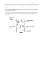
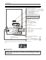
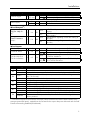
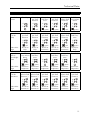
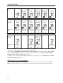
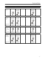
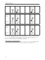
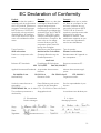
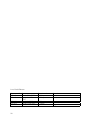
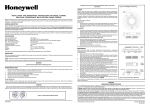
SPECIALISTS IN SECURITY-ORIENTED TELECOMMUNICATIONS Wall Transmitter Ncall N46 User Manual Document 952.41d Document No 952.41d Wall transmitter Ncall N46 : User Manual Edition: November 2003 Editor: Daniel Schwendener TELECTRONIC SA 2003 All rights reserved. TELECTRONIC SA reserves the right to make changes to the information contained in this document at any time without prior notice. Great care has been given to the contents of this document ; however TELECTRONIC SA cannot be held liable for the consequences of any errors or omissions contained herein or for consequential or incidental damages incurred as a result of acting on information contained in the document. TeleAlarm® is a registered trade mark of TELECTRONIC SA. TELECTRONIC SA www.telealarm.com CH - 2300 LA CHAUX-DE- FONDS HEAD OFFICE, R&D, PRODUCTION and AFTER-SALES SERVICE Rue du Nord 176 Tel: +41 (0)32 911 11 11 Fax: +41 (0)32 911 11 00 CH – 8307 EFFRETIKON SALES, AFTER-SALES SERVICE Bahnhofstrasse 28 Tel: +41 (0)52 355 13 00 Fax: +41 (0)52 343 38 25 2 QU A LI T Y CE RTIFIED Contents Contents Contents 3 Terminology.................................................................................................................... 3 Models and Options ........................................................................................................ 3 General Description 4 Performance Characteristics.............................................................................................. 4 Installation 6 Wall Mount..................................................................................................................... 6 Connection Compartment ................................................................................................ 6 Power Supply .................................................................................................................. 7 Reset .............................................................................................................................. 7 Transmitter Identification................................................................................................... 7 Operation Check............................................................................................................. 7 Configuration and Wiring ................................................................................................. 8 Inputs and Outputs .......................................................................................................... 9 General Configuration ..................................................................................................... 9 Use 10 Call for Help ................................................................................................................. 10 Call for Assistance ......................................................................................................... 10 Call Acknowledgement (Presence Signal).......................................................................... 11 Call for Help 2 (reserve) ................................................................................................. 11 Technical Alarm ............................................................................................................ 11 Caregiver Arrival(o) ......................................................................................................... 12 Caregiver Departure(o) .................................................................................................... 12 Daily Message and Battery Low Message.......................................................................... 12 Error Message ............................................................................................................... 12 Technical Data 13 General Data................................................................................................................ 13 Mode of Operation........................................................................................................ 14 Legend of Illustrations: ................................................................................................... 14 Staff Presence Processing Activated .................................................................................. 15 Staff Presence Processing Disabled .................................................................................. 17 Terminology In this manual, the status of inputs and outputs is described with the terms activated or released : • Activated means that the contact of an NO input or output is closed, or that the contact of an NC input or output is open. The activated state is always represented by the symbol . • Released means that the contact of an NO input or output is open, or that the contact of an NC input or output is closed. The released state is always represented by the symbol . Models and Options (o) The availability of the functions or specifications marked with this abbreviation depends on the chosen model or options. 3 General Description General Description In the Nursecall system, the Wall Transmitter NCall N46 allows the resident of a home or the patient of a clinic to easily alert the care personnel if needed. The patient simply has to push the large red button. The system is then able to control and to monitor the progress of the Care Personnel. The transmission is mainly performed by radio. There is no need for a wired connection between the Transmitter and the Reception Unit, this makes the system installation easy and allows great mobility. Depending on the model, two relay outputs(o) are available which may be used to connect alarm and staff presence indicators such as, for instance, the signal lamps installed above the door. Two signal lamps (LED) allow the progress to be monitored on the device. In this User Manual you will find all the information you need for the installation and the use of the Wall Transmitter NCall N46. Performance Characteristics With its multi-functionality, the Wall Transmitter NCall N46 fulfils the toughest requirement in all social and medical areas such as homes for elderly people, clinics or hospitals. The following are the key performance characteristics of the Wall Transmitter NCall N46: • • • • • • • • • • • • • • • • • 4 Fast installation and mobility achieved by radio transmission of the calls (no wiring needed) Driving of the lamps used to display the calls and the staff presence status by way of two relay contact outputs(o) Indication of the intervention state by LEDs Provision for a12 to 24 VDC external power supply High working reliability secured by the transmission of a programmable daily message and automatic controls Wall mount or on any type of support A large red button with cam structure is used to trigger the Calls for Help A blue button allows the Care Personnel to summon assistance if needed A third acknowledgement button (green) is used by the Caregivers to signal their presence and the end of their intervention A phone jack ∅ 3,5 mm allows to connect a remote Call for Help button on a long cable in order to make it easier to trigger the Call for Help Possibility to transmit arrival and departure of up to four different categories of Caregivers Secured connection of the phone jack prevents the cable from being pulled out accidentally Detection and transmission in case of the remote Call for Help button is pulled out A terminal block allows connection of up to three external triggering devices for additional calls or alarms. The configuration carried out by jumpers and solder-bridges allows to adapt the device to many uses The connection compartment is easily reached for configuration, wiring and maintenance (check and change of battery) Long term battery life with standard CR 2450 lithium battery General description The three coloured buttons provide, in most cases, the most common form of operation. The large red button with cam structure is used to trigger the Call for Help. The round blue button triggers the Call for Assistance. These two alarms are repeated automatically about every 2 minutes until the green acknowledgement button has been pressed. The signal lamp on the top of the red button goes on every time a radio-transmission takes place and is used to indicate the alarm status on the transmitter. A second signal lamp indicates the presence status. Signal lamps (LED): presence Acknowledgement Button alarm Call for Help Button Call for Assistance Button Connection compartment Figure Figure 1 5 Installation Installation Wall Mount The Wall Transmitter NCall N46 can be fixed with two to five screws on a wall. Two holes at 60 mm interval are provided for direct mounting on connection boxes. The three upper holes are used for positioning the device and cannot be reached from the Connection Compartment. Two of the lower holes can be reached from outside and thus used for fixing the device. 80 13.1 53.8 3.7 16 6.6 .5 Ø7 27 131 59.9 3.7 18.1 26 2 Figure 2 Connection Compartment Most of the wiring, configuration and maintenance functions such as : • • • • • Connection of the external power supply Connection of the wired inputs and outputs Choice of the triggering edge of external Call for help trigger, Technical Call and Call for Help 2 inputs (normally open or normally closed) at jumpers J1, J2 and J3 Installation or replacement of battery Checking of the battery voltage can be carried out in the connection compartment. It is reached by taking off the lower part of the housing (see Figure 1). This can be done even if the device is fixed on the wall. The connection cables can be channelled towards the outside through the hole next to the terminal blocks or downwards by breaking off part of the rear housing. 6 Installation Power Supply The Wall Transmitter NCall N46 can be powered by a lithium battery or/and an external 12-24 VDC power supply. If the device is powered with an external power supply, the battery is not necessary, but it can be used as a backup power supply in case of power loss. If the device is powered by the battery only, the battery life is about 2 years. However it is advisable to change the battery once a year. If the device is powered by an external power supply and the battery is used as backup power supply, it is advisable to check it at regular intervals (for instance once a year) and to change it if necessary. Reset All parameters are reset when powering up the device (battery or external power supply). This operation causes the synchronization of the daily message. In order to perform a reset, make sure to remove both the battery and the external power supply, do a short-circuit on the two pins marked Reset on the next figure before powering the device up again. Important Note: All connections as well as the configuration need to be carried out before powering the device (insertion of the battery and/or application of the external power supply). Transmitter Identification All Wall Transmitters NCall N46 are provided with their own radio identification code that is assigned when manufactured. During the installation, it is necessary to set the relation between the identification code of the Transmitter and the place where it is installed (floor/room/bed or single number). This relation is programmed on the Master Nursecall Unit (refer to the Nursecall User Manual). Operation Check Once the transmitter has been installed and set-up properly, it is recommended to check all functionalities of the device. The radio transmission can be checked by sending an acknowledgement call (press green button). 7 Installation Configuration and Wiring Solder Bridges (if soldered): B8 Call for Assistance only by Staff Presence B7 Call for Assistance from terminals J6[4-5] B6 No Staff Presence processing B5 No Daily Message B4 No calling message repetition B3 Technical Alarm message repetition B1(o) REL 1 Call for Help polarity (o) B2 REL 2 Staff Presence polarity B8 B7 B6 B5 B4 B3 Terminal J5: 1 External 12-24 VDC power supply 2 GND (0 V) (o) 3-4 REL 1 Call for Help (o) 5-6 REL 2 Staff Presence NO NO NC B1 NO NC B2 REL 1 REL 2 CR 2450 battery Reset (o) J7 Terminal J6: 4-5 Call for Help 2 or Call for Assistance NO NC J1 3-4 Technical Alarm NC J2 NO NC J3 J5 1 2 3 4 5 6 Connector J7 : Presence/Staff identification J4 1-2 Call for Help 5 4 3 2 1 J6 J1 External Call for Help trigger input polarity Connector J4: External Call for Help trigger J2 Polarity of Technical Alarm input J3 Polarity of terminal J6[4-5] input Solder bridges B1 and B2 are located on the bottom side of the PCB: NC-B2-NO NC-B1-NO (bottom view) Important Note: Setting-up one or more inputs to "NC" position results to higher power consumption. This configuration should be used with external power supply or will reduce the battery life. 8 Installation Inputs and Outputs External trigger J4 Jack 3.5 mm Power supply J5 1 2 J1 NO* NC Contact closing causes a Call for Help Contact opening causes a Call for Help + - 12 to 24 V DC GND 0V Wired Outputs(o): Call for Help Relay(o) J5 Staff Presence Relay(o) J5 3-4 NC 5-6 B2 NO* NC Wired Inputs: Call for Help J6 1-2 Technical Alarm J6 3-4 Call for Help 2 or Call for Assistance B1 NO* J6 4-5 J2 J3 NO* NC NO* NC A Call for Help causes the closing of the relay contact A Call for Help causes the opening of the relay contact Staff Presence signalling causes the closing of the relay Staff Presence signalling causes the opening of the relay The contact closing causes a Call for Help The contact closing causes a Technical Alarm The contact opening causes a Technical Alarm The contact closing causes a Call for Help 2 or a Call for Assistance The contact opening causes a Call for Help 2 or a Call for Assistance *Delivery state General Configuration Bridge State Open* B3 Soldered B4 B5 B6 B7 B8 Open* Soldered Open* Soldered Open** Soldered** Open* Soldered Open * Soldered Function Technical Alarms are not repeated Technical Alarms are repeated until alarm acknowledgement (max 20 min.) Calls (except technical alarms) are repeated until call acknowledgement (max 20 minutes) Calls (except technical alarms) are not repeated A daily message is sent every 24 hours Daily messages are suppressed Staff Presence Processing is activated Staff Presence Processing is disabled Activation of J6 [4-5] terminal input causes a Call for Help 2 Activation of J6 [4-5] terminal input causes a Call for Assistance The Assistance Call does not depend on the presence of the Care Personnel The Assistance Call is possible only if the Care Personnel has signalled his/her presence * Delivery state ** N46 Wall transmitters that feature the output relays are delivered with the Staff Presence Processing activated (B6 open), models that do not feature the output relays are delivered with the Staff Presence Processing disabled (B6 soldered). 9 Use Use Every time the Wall Transmitter NCall N46 is used by pressing a button or activating a wired input, the device sends a radio signal and the lamps indicates its actual state. Two relays allow the transmission of status to a remote display such as the signal lamps placed on top of the door. Each radio message is sent with a different code which allows the receiver (Nursecall system) to recognize the action performed. The Wall Transmitter NCall N46 transmits the described next criterions. It is advisable to keep the button pressed until the lamp placed above the red button lights up. Call for Help The Call for Help can be triggered in three different ways: By pushing the Call for Help button (red) By pushing the external switch connected to the J4 connector By pushing the external button connected to terminals 1 and 2 of the terminal block J6. • • • The Call for Help is repeated about every 2 minutes until a call acknowledgement takes place, up to a maximum of 20 minutes. This repeat function can be disabled by setting the solder bridge B4. A Call for Help is signalled by red flashes on the signal lamp and by the activation of the relay(o) Call for Help. Note: In some cases, the action Call for Help generates a Call for Assistance1 action. Call for Assistance The Call for Assistance is triggered by pushing the Call for Assistance button (blue). The Call for Assistance is repeated about every 2 minutes until a call acknowledgement takes place, up to a maximum of 20 minutes. This repeat function can be disabled by setting the solder bridge B4. A Call for Assistance is signalled by red double flashes on the signal lamp and by the alternate action/release of the relay(o) Call for Help. Note: In some cases, the action Call for Assistance generates a Call for Help1 action. 1 See chapter Mode of Operation (page 14) 10 Use Call Acknowledgement (Presence Signal) The call acknowledgement is triggered by pushing the Acknowledgement button (green). The call acknowledgement stops immediately all repetitions of the calls. A call acknowledgement triggers the Staff Presence signal: • by green flashes on the signal lamp and by activating the Staff Presence relay(o) when the Caregiver pushes the Acknowledgement button when entering the room. • by switching off the lamp and releasing the Staff Presence relay(o) when the Caregiver pushes the Acknowledgement button and leaves the room. Note: In some circumstances the device may react differently to the acknowledgement of a call 2. Call for Help 2 (reserve) The Call for Help 2 is triggered by pushing the external button connected to terminals 4 and 5 of terminal block J6. The call can be triggered by closing (NO) or opening (NC) the contact3. The Call for Help 2 is repeated about every 2 minutes until a call acknowledgement takes place, up to a maximum of 20 minutes. This repeat function can be disabled by setting the solder bridge B4. The Call for Help 2 is signalled in the same way as the Call for Help on the signal lamp and the relays(o). Technical Alarm The Technical Alarm is triggered by activating the contact connected to terminals 3 and 4 of terminal block J6. The alarm can be triggered by closing (NO) or opening (NC) the contact3. Normally, the Technical Alarm is not repeated, but it is possible to activate the repetition of the technical alarms by setting the solder bridge B3.. In this case, the Technical Alarm is repeated about every 2 minutes until a call acknowledgement takes place, up to a maximum of 20 minutes. The Technical Alarm is signalled in the same way as the Call for Help on the signal lamp and the relays(o). 2 3 See chapter Mode of Operation (page 14) See chapter Configuration and Wiring (page 8) 11 Use Caregiver Arrival(o) The Caregiver Arrival message is triggered when the Caregiver inserts the coded key in the connector on the side of the housing (J7), when entering the room. Up to four categories of Caregivers may be identified by using different keys. The Caregiver Arrival message is not repeated. Insertion of the coded key is signalled by green flashes on the signal lamp and by activating the Staff Presence relay(o) Note: In some circumstances the device may react differently when the coded key is inserted4. Caregiver Departure(o) The Caregiver Departure message is triggered when the Caregiver removes the coded key from the housing, when leaving the room. The Caregiver Departure message is not repeated. Removing the coded key is signalled by switching off the green flashes on the signal lamp and by releasing the Staff Presence relay(o) Note: In some circumstances the device may react differently when the coded key is removed4. Daily Message and Battery Low Message The radio transmission can be checked by way of the Daily Message which is automatically sent about every 24 hours. When the battery voltage is too low, the Daily Message is replaced by a Battery Low Message. The transmission of the Daily Message can be disabled by setting the solder bridge B5 (this does not influence the transmission of the Battery Low message). Error Message The Error Message is sent every 2 minutes if the device has detected a general dysfunction, or if one of the following triggering devices remains in its activated position for up to 4 minutes: • • • • Call for Help Acknowledgement button Call for Assistance Call for Help 2 Note: The device connected to the Technical Alarm input is allowed to remain in the activated position; without transmission of the Error Message. 4 See chapter Mode of Operation (page 14) 12 Technical Data Technical Data General Data HOUSING Plastic case ASA for wall mount (L x H x P) Weight 133 x 82 x 26 mm about 200 g BATTERY POWER SUPPLY: Lithium battery Current consumption in stand-by mode Peak current consumption at alarm transmission Battery autonomy Type CR 2450 (3 V) max 10 µA max 30 mA 2 years EXTERNAL POWER SUPPLY Current consumption in stand-by mode Peak current consumption at alarm transmission +12-24 VDC max 10 mA max 40 mA RADIO TRANSMISSION PART Transmission frequency Channel Modulation Duration of transmission Stability (-10°C ... +70°C) 434,01 MHz 1 FSK (F1D) <1 s ± 10 ppm OUTPUT RELAY(o) Max. switching power Max. switching voltage Max. switching current 125 VA / 60 W 48 V DC 2A CODED KEYS Key with code 07 Key with code 08 Key with code 09 Key with code 10 R = 3.3 kΩ R = 4.7 kΩ R = 10 kΩ R = 22 kΩ Technical data is subject to changes. 13 Technical Data Mode of Operation During operation, the Wall transmitter NCall N46 can be set to one of six following states: State Stand-by Alarm without Staff Presence Alarm with Staff Presence Assistance without Staff Presence Assistance with Staff Presence Staff Presence without alarm Description No call is being processed. The patient has triggered a Call for Help but the Care Personnel has not yet responded. The Care Personnel has responded after a Call for Help. A Call for Assistance has been triggered without the presence of the Care Personnel. A Call for Assistance has been triggered in the presence of the Care Personnel. The Care Personnel has responded without the previous call from the patient. Each state is indicated by the signal lamp and by a special position of the output relays(o). It is possible to configure5 the Wall Transmitter NCall N46 in order that: • the Call for Assistance can be triggered only if the Care Personnel is present. • the device does not manage the Staff Presence. This mode makes sense only if the output relays(o) are not provided or not used. The transition to a specific condition depends on the device configuration, of its actual condition and of the action completed; as shown on the following charts. Note: When the Wall Transmitter NCall N46 is powered by an external power supply, the signal lamps follow the state of the corresponding relay outputs. Legend of Illustrations: The contact of the Call for Help relay(o) is activated The contact of the Call for Help relay(o) is released A A The contact of the Call for Help relay(o) opens and closes alternately A P The contact of the Staff Presence relay(o) is activated The contact of the Staff Presence relay(o) is released The signal lamps are off P 5 colour A signal lamp lights up in the indicated colour colour A signal lamp "flashes" in the indicated colour colour ! A signal lamp generates "double-flashes" in the indicated colour Transmission of a radio message See chapter Configuration and Wiring (page 8) 14 Technical Data Staff Presence Processing Activated State before action Stand-by A P Alarm without Staff Presence A P Alarm with Staff Presence A P red State after a Call for Help Alarm without Staff Presence A P Radio Message red !Call for Help Staff PresState after a ence without call acalarm knowledgement A P Alarm without Staff Presence A P Assistance with Staff Presence A P A P green green Assistance with Staff Presence Assistance with Staff Presence A P Assistance Staff Preswithout Staff ence without Presence alarm A P A P green red Assistance without Staff Presence A P Alarm with Staff Presence A P red !Call for Help green !Call for Assistance green ! Call for Assistance red ! Call for Assistance green !Call for Help Alarm with Staff Presence A P Stand-by* Alarm with Staff Presence A P Alarm with Staff Presence A P Stand-by* A P A P Radio Message green !Acknowledgement green !Acknowledgement !Acknowledgement green !Acknowledgement green !Acknowledgement !Acknowledgement State after a Call for Assistance Assistance Assistance without Staff without Staff Presence ** Presence ** Assistance with Staff Presence Assistance with Staff Presence Assistance without Staff Presence Assistance with Staff Presence A P Radio Message A P red red !Call for !Call for Assistance** Assistance** A P green !Call for Assistance A P green !Call for Assistance A P red !Call for Assistance A P green !Call for Assistance 15 Technical Data State before action Stand-by A P Alarm without Staff Presence A P Alarm with Staff Presence A P red State after coded key insertion(o) Staff Presence without alarm A P Radio Message State after coded key removal(o) green !Staff arrival with code Stand-by A P Radio Message !Staff departure with code Alarm with Staff Presence A P green !Staff arrival with code Assistance with Staff Presence A P A P green green Alarm with Staff Presence Assistance with Staff Presence A P green !Staff arrival with code Not possible Stand-by*** A P !Staff departure with code Assistance Staff Preswithout Staff ence without Presence alarm A P green !Staff arrival with code A P Alarm with Staff Presence A P green !Staff arrival with code Assistance Not possible without Staff Presence A P red !Staff departure with code green red Staff Presence without alarm A P green !Staff arrival with code Stand-by A P !Staff departure with code * There is no state change when the coded key is inserted. **If the function Assistance only in case of Staff Presence is activated and the NCall N46 is not in Staff presence state, the Call for Assistance causes a state Alarm without Staff Presence and a Call for Help radio message. *** If the call has not been acknowledged, removing the key will turn the NCall N46 in Alarm without Staff Presence state. Calls for Help 2 and Technical Alarms: Actions Calls for Help 2 and Technical Alarms are indicated in the same way as a Call for Help, but the criterion transmitted by the radio message corresponds to the triggered action. 16 Technical Data Staff Presence Processing Disabled State before action Stand-by A P Alarm without Staff Presence A P Assistance without Staff Presence A P red State after a Call for Help Alarm without Staff Presence A P Alarm without Staff Presence A P red Assistance without Staff Presence A P red !Call for Help red ! Call for Help red ! Call for assistance State after a call acknowledgement Stand-by A P Stand-by A P Stand-by A P Radio Message !Acknowledgement !Acknowledgement !Acknowledgement State after a Call for Assistance Assistance Assistance without Staff without Staff Presence * Presence * Assistance without Staff Presence Radio Message A P Radio Message red ! Call for Assistance* A P red ! Call for Assistance* A P red ! Call for Assistance 17 Technical Data State before action Stand-by A P Alarm without Staff Presence A P Assistance without Staff Presence A P red State after coded key insertion(o) Stand-by A P Radio Message !Staff arrival with code State after coded key removal(o) Stand-by A P Radio Message !Staff departure with code Alarm without Staff Presence A P red Assistance without Staff Presence A P red !Staff arrival with code red !Staff arrival with code Alarm without Staff Presence Assistance without Staff Presence A P red !Staff departure with code A P red !Staff departure with code * If the function Assistance only in case of Staff Presence is activated, the Call for Assistance causes a state Alarm without Staff Presence and a Call for Help radio message. This configuration cancels the processing of the Calls for Assistance. Calls for Help 2 and Technical Alarms: Actions Calls for Help 2 and Technical Calls are indicated in the same way as Call for Help, but the criterion transmitted by the radio message corresponds to the triggered action. 18 EC Declaration of Conformity English : We declare that this product complies with the requirements of the EC Radio & Telecommunications Terminal Equipment R&TTE Directive 1999/5/EC, specifically with requirements detailed below. All modifications made without our agreement will invalidate this declaration. Français : Nous déclarons que ce produit est, dans sa conception et construction, conforme aux exigences de la directive R&TTE 1999/5/UE de l’Union Européenne, spécifiquement selon les directives et normes détaillées ci-dessous. Toute modification apportée au produit sans notre approbation annule cette déclaration. Type of product : Deutsch : Hiermit erklären wir, dass das nachfolgend bezeichnete Erzeugnis aufgrund seiner Konzipierung und Bauart den einschlägigen grundlegenden Anforderungen der EU R&TTE Richtlinie 1999/5/EU, insbesondere nachfolgend genannten Richtlinien, entspricht. Bei einer nicht mit uns abgestimmten Änderung des Erzeugnisses verliert diese Erklärung ihre Gültigkeit. Bezeichnung des Erzeugnisses : Wall-transmitter Mehrkriterien-Funkmelder Emetteur multicritères Product or component reference : Gerätetyp/Bezeichnung der Einzelkomponenten : Dénomination de l’appareil ou des composants : Type de produit : Ncall N46 Relevant EC Standards: Einschlägige EU-Richtlinien: LDV 73/23/EEC EMC 89/336/EEC Applied Harmonised Standards: Angewandte harmonisierte Normen: EN 60950 A1-A4 Directives normatives EC : EN 50130-4 Normes harmonisées appliquées : EN 55022 class 2 ETS 300220-1 Notified Body: Benannte Stelle: Organisme notifié: Under the manufacturer responsibility: Diese Erklärung wird verantwortlich für den Hersteller: Sous la responsabilité du producteur: TELECTRONIC SA, rue du Nord 176, CH-2300 La Chaux-de-Fonds This conformity statement is declared by: D. Schwendener Product Manager Abgegeben durch: La conformité est déclarée par: P. A. Nicati Managing Director 19 List of Valid Editions Document N° 952.41 952.41a 952.41b 952.41c 952.41d 20 Date March 21th 1997 September 17th 1997 May 04th 1998 January 27th 2001 November 10th 2003 Editor/ translator T. Ganyi T. Ganyi T. Ganyi T. Ganyi D. Schwendener Remark Upgrade to N46


![LTRT-71403 MediaPack MGCP User Manual ver 4[1].](http://vs1.manualzilla.com/store/data/005760883_1-b98cf40cc1cd8cff0fa8bbf345d132db-150x150.png)