1
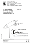
Operating Instructions
1.002.0224
●
Go/RB
●
12/02
●
GB 05.00
e@syDrive® 4424
KaVo Elektrotechnisches Werk GmbH
Wangener Straße 78
D-88299 Leutkirch
Tel.: 0 75 61 / 86-0 • Fax: 0 75 61 / 86-371
e@syDrive 4424
A 1 User information . . . . . . . . . . . . . . . . . . . . . . . . . . . . . . . . . . . . . . . . . . . . . . . . . . . . . . . . . . 2
A 1.1 Meaning of the pictograms . . . . . . . . . . . . . . . . . . . . . . . . . . . . . . . . . . . . . . . . . . . . . . . . . . . . . . . . 2
A 1.2 Important information . . . . . . . . . . . . . . . . . . . . . . . . . . . . . . . . . . . . . . . . . . . . . . . . . . . . . . . . . . . . 2
A 1.3 Precautions . . . . . . . . . . . . . . . . . . . . . . . . . . . . . . . . . . . . . . . . . . . . . . . . . . . . . . . . . . . . . . . . . . . 3
A 1.4 Purpose and potential applications . . . . . . . . . . . . . . . . . . . . . . . . . . . . . . . . . . . . . . . . . . . . . . . . . . 4
A 1.5 Technical data . . . . . . . . . . . . . . . . . . . . . . . . . . . . . . . . . . . . . . . . . . . . . . . . . . . . . . . . . . . . . . . . . 5
A 2 Scope of delivery - Accessories . . . . . . . . . . . . . . . . . . . . . . . . . . . . . . . . . . . . . . . . . . . . . . 7
A 2.1 Scope of delivery . . . . . . . . . . . . . . . . . . . . . . . . . . . . . . . . . . . . . . . . . . . . . . . . . . . . . . . . . . . . . . . 7
A 2.2 Accessories . . . . . . . . . . . . . . . . . . . . . . . . . . . . . . . . . . . . . . . . . . . . . . . . . . . . . . . . . . . . . . . . . . . 7
A 3 LED/Operation . . . . . . . . . . . . . . . . . . . . . . . . . . . . . . . . . . . . . . . . . . . . . . . . . . . . . . . . . . . . 8
A 4 Rating plate . . . . . . . . . . . . . . . . . . . . . . . . . . . . . . . . . . . . . . . . . . . . . . . . . . . . . . . . . . . . . . 9
A 5 Connection of KaVo-Spindles . . . . . . . . . . . . . . . . . . . . . . . . . . . . . . . . . . . . . . . . . . . . . . . 10
A 6 Block diagram motor control . . . . . . . . . . . . . . . . . . . . . . . . . . . . . . . . . . . . . . . . . . . . . . . . 11
B 1 Assembly and Installation, for cabinet mounting . . . . . . . . . . . . . . . . . . . . . . . . . . . . . . . . 12
B 1.1 Assembly . . . . . . . . . . . . . . . . . . . . . . . . . . . . . . . . . . . . . . . . . . . . . . . . . . . . . . . . . . . . . . . . . . . . 12
B 1.3 Wiring guidelines for compliance with the EMC standards . . . . . . . . . . . . . . . . . . . . . . . . . . . . . . . . 13
B 1.4 Access to electrical connections . . . . . . . . . . . . . . . . . . . . . . . . . . . . . . . . . . . . . . . . . . . . . . . . . . . 14
B 1.5 Motoranschluss / Spannungseingang . . . . . . . . . . . . . . . . . . . . . . . . . . . . . . . . . . . . . . . . . . . . . . . 15
B 1.6 Connection of remote control . . . . . . . . . . . . . . . . . . . . . . . . . . . . . . . . . . . . . . . . . . . . . . . . . . . . . 16
B 2 Fault indications . . . . . . . . . . . . . . . . . . . . . . . . . . . . . . . . . . . . . . . . . . . . . . . . . . . . . . . . . . 17
B 2.1 Description of all warnings and faults . . . . . . . . . . . . . . . . . . . . . . . . . . . . . . . . . . . . . . . . . . . . . . . 17
Declaration of confority . . . . . . . . . . . . . . . . . . . . . . . . . . . . . . . . . . . . . . . . . . . . . . . . . . . . . . . . . . . . . . 19
1
e@syDrive 4424
A 1 User information
A 1.1 Meaning of the pictograms
Situation which may lead to danger, damage to material or operating faults in the event of failure to
follow the instructions.
Important information for
operator and engineer.
A 1.2 Important information
The Operating Instruction must be read by the user/operator prior to commissioning, in order to avoid
incorrect operation and other damage. If further language versions are required, please request them from
your responsible KaVo agent. Duplication and distribution of the Operating Instruction (OI) require prior consent
from KaVo.
All technical data, information and properties of the product described in this UM correspond to the state on
going to press.
Modications and improvements to the product on the basis of new technical developments are possible.
This does not imply any right to retrofitting of existing devices.
KaVo assumes cannot be held responsible for damage arising through:
•
•
•
•
external influences (poor quality of the media or poor installation)
use of incorrect information
improper use
improperly performed repairs.
Repair and maintenance work - except for the activities described in this User Manual - may be performed only
by qualified specialists.
In the event of modifications by third parties, the approvals shall become null and void. KaVo recommends using
only original spare parts for operation and for repair.
For safety reasons, the inverter supplied is not configurable. Only those spindles must be connected that
are named in the summary table on page 10 (A5 Inverter Types).
2
e@syDrive 4424
A 1.3 Precautions
Safe operation and protection of the device is ensured only by proper use, in accordance with the User Manual,
with the tools approved for this purpose. The following should also be observed:
• Industrial safety regulations
• Accident prevention regulations
Before installation and commissioning of this device, please read this safety and warning information carefully
and observe all warning signs mounted on the device.
■ The frequency inverter type e@sy drive4424 controls dangerously rotating mechanical parts and generates
dangerous electrical voltages. If these operating instructions are not followed, severe damage to property,
injuries and even death may result.
■ Safe operation of this device depends on the proper installation, handling and operation of the device.
■ Only appropriately qualified personnel may put this device into operation, maintain it and work on it.
Connection, commissioning and rectification of faults may be performed only by specialists.
■ The device has no mains switch. When working on the open device, it must be completely disconnected from
the mains beforehand. The device has no mains input fuses.
■ The capacitor of the DC voltage intermediate circuit remains charged with dangerously high voltage for some
time even after the mains voltage has been switched off. It is essential to wait for two minutes after switching
off the mains voltage before opening the device.
■ This device may start up automatically with certain settings after a mains failure.
■ This device may not be used as an “emergency stop mechanism” (see EN 60204).
■ The device may be used only for the purpose intended by the manufacturer. Unauthorized modifications and
the use of additional equipment not recommended by the manufacturer can cause fires, electric shocks and
injuries.
Definitions
ASM motor
3-phase asynchronous motor
BLDCMotor
3-phase brushless DC motor without position sensors
The inverter performs the position synthesis by measuring the motor voltage (e.m.f.).
Danger
In the context of this User Manual and of the warnings mounted on the device, this means
that death, serious injury or considerable damage to property may occur if the corresponding
precautions are not taken.
Note
In the context of this User Manual, a note constitutes important information which is of particular importance for the understanding and the operation of the device.
Qualified
personnel
are in the context of this User Manual persons who are familiar with the installation, assembly,
commissioning and operation of the product and with the possible dangers.
Caution
In the context of the User Manual and of the warning signs mounted on the device, this
means that slight injury or damage to property may occur if the corresponding precautions are
not taken.
Warning
In the context of the User Manual and of the warning signs mounted on the device, this
means that death, serious injury and considerable damage to property may occur if the corresponding precautions are not taken.
PLC
Programmable Logic Controller, controller of a superior level machine.
3
A 1.4 Purpose and potential applications
KaVo EWL frequency inverters, type e@sy drive4424, have been specially designed for the operation of threephase asynchronous motors (ASM) and brushless DC motors (BLDC), as used in spindles, e.g. for grinding, cutting and drilling units on machine tools.
They can also be used for operating motors which are constructed from motor elements and serve, for example,
as a drive for test stands or other physical equipment (e.g. vacuum pumps, centrifuges, optical systems etc.).
Gentle operation of the motors is achieved by the pulse amplitude modulation (PAM) used.
Specifically, the following motor types can be operated:
- Asynchronous motors (ASM) (standard)
- Brushless DC motors without sensors (BLDC) (option)
EWL 4025, 4026, 4029
EWL 4015
An integrated load compensation offers high speed constancy and - through low idling currents - avoids unnecessary heating up of the connected motors.
On stop command, the connected motor is decelerated down to zero speed.
The control and monitoring of the inverter are performed by several microprocessors. This ensures high reliability and flexibility.
The inverter can either be controlled via the PLC-compatible remote control or manually.
The inverter is cooled by an integrated fan.
4
e@syDrive 4424
A 1.5 Technical data
Frequency inverter
Operation
via the PLC-compatible remote control or manual
Display
LED for Ready (green) // Fault (red)
Dimensions
75 mm witdht, 310 mm height,, 215 mm depth for installtaion in cabinet
Operating
temperature
Humidity of the air:
Weight
5 ... 40°C
lower than 90 % relative humidity, non-condensating
approx. 3 kg
Tests and
standards
Ingress protection
VDE tested according to EN 50178
EMV according to 61800-3
IP20 acc DIN 40050 for open version
IP00 acc DIN 40050 for enclosed version
All inverter types in open version (IP00) must only be installed as rack-mounted models. This means that
protections against accidential contact, isolating switch as well as Standards and tests according EN
50178 (VDE) and EN 61800-3 (EMC) have to be provided by the installer.
The frequency inverter 4424 has been designed for variable speed control of KaVo-Spindles (see section
A5). Pulse Amplitude Modulation (PAM) with 120°-blocks is used to set the output voltage.
Power unit
Electrical connection
Input power
Output voltage
Output current
Output frequency
Output power
Braking resistance
Efficiency
single-phase max. 38V~, 50/60 Hz or max. 53V
max. 300 VA
max. 3 * 33 V~
max. 6 A~per phase at 16V motor voltage
max. 5 A~ per phase at 22 V motor voltage
max. 4 A~ per phase at 28 V motor voltage
83 ... 1666 Hz for ASM motors
83 ... 1666 Hz for BLDC motors
max. 180 W continuous operation
internal
93 % (at 250 VA, cos phi motor 86 %)
5
e@syDrive 4424
Remote control
Start signal Inputs
• Start signal with external contact
• Start with external voltage
+ 24 V (level 15....30 V)
0 V (ground)
For faultless detection of the start signal the inverter 4424 needs to see a clear signal edge from “low” to
“high”. A re-start signal is needed after power-off. Only one of the two start inputs must be used. Start
input terminals must not be bridged or bypassed.
Relay Outputs
• Relay No 1
• Relay 2
NO contact, max. 48 V~, 1 A, max. 30 V=, 1 A
min. current 1 mA at 24V (10mA at 10V)
Function: Up-to-speed
NO contact, max. 48 V~, 1 A, max. 30 V=, 1 A
min. current 1 mA at 24V (10mA at 10V)
Function: Up-to-speed
Relay outputs are potential free (galvanic isolation).
Analouge Inputs
• 0…10V
+10 V• +10 V
Ue = 0...10 V, Re = 100 kΩ, Ie = 0,1 mA at 10 V,
w/o connection 0V, input protected up to max. ± 40 V
Function: Analogue speed set value
Potentiometer-output:
Voltage supply Uo = 10 V, Io = max.2 mA,
FB-voltage outputs rerference is ground “FB-Masse”.
6
e@syDrive 4424
A 2 Scope of delivery - Accessories
A 2.1 Scope of delivery
Frequency inverter type 4424
Technical manual Mat.-No. 1.001.0224
Frequency inverter type 4424
Technical manual Mat.-No. 1.001.0224
A 2.2 Accessories
Power module for inverter type 4424 Mat.-Nr. 1.002.0061 (available as enclosured version only)
7
e@syDrive 4424
A 3 LED/Operation
LED Ready/Fault
Green:
Green flashing:
Red:
Red flashing:
Operating
Software identification after power-on
Fault
Number of flashing cycles refers to fault code
Please refer to Fault Codes in section B 2 for further information.
LED
Control:
Usually the PLC compatible remote control is used to operate the device.
8
e@syDrive 4424
A 4 Rating plate
The device has been tested according requirements of the European Standard EN 50178
Rating plate
Rating plate for enclosed types
inverter type
Mat.no.
serial no.
test label
input power
output power
Typenschild für offene Version
inverter type
Mat.no.
serial no.
test label
input power
output power
9
e@syDrive 4424
A 5 Inverter types and matching KaVo-Spindle types
Each inverter type of the e@syDrive® 4424 series is adjusted to a certain KaVo-Spindle type and can only be
used for this type. Please refer to below table for matching pairs:
Combination of inverters/inverter versions with matching power modules und spindles
Inverter types
4424-D25
4424-D33R+
4424-D33T+
4424-A33
Enclosed version (IP20)
REF 10019109
REF 10019110
REF 10020752
REF 10019291
Open version (IP00)
REF 10020294
REF 10020690
REF 10020753
REF 10020751
Matching Power Modul
(IP20)
Matching Spindel type
4424-NT (REF 10020061)
D25
1)
D33R+
2)
D33T+
3)
A33
4)
1) D25:
Micro-Spindle with housing diameter 25,4mm (1 inch) and BLDC-motor, e.g. spindle type 4015
2) D33R+:
HF-Spindle series with housing diameter 33 mm and BLDC-motor, high speed version
3) D33T+:
HF-Spindle series with housing diameter 33 mm and BLDC-motor, high torque version
4) A33:
HF-Spindle series with housing diameter 33 mm and ASM-motor, e.g. spindle type 4025
On first operation ensure that spindle rotates in correct direction! (Please refer to rotation direction arrow
on spindle!)
Compliance with EMC-Standards is only ensured if spindles with shielded motor cable are used!
10
e@syDrive 4424
A 6 Block diagram motor control
Leuchtdiode Betrieb / Störung /
Software-Versionsanzeige
Analoge Eingänge / analogous inputs
+10V
+10V
A
56.2k
Eingang 0...10V (Drehzahlsollwert,speed control)
0...10V
Bezugspunkt analog
common analogous
GND
D
GND
Start - Inputs
manueller
Start
10k
3.9k
+24V
SPS - Start
0V
Relaisausgänge / relay outputs
Drehzahl erreicht
speed reached
Betrieb / Störung
operation /error
Bezugspunkt / Common
COM
Motorsteuerung
motor contol
Regelung
control
GS - Gleichstromsteller /
DC control
GR - Gleichrichter /
rectifier
GR
Spannungseingang
supply input
max 38V~ 50/60Hz
GS
WR
38V~
WR - Wechselrichter /
AC converter
Bremse
break
Motor / motor
U
M
M
3~
V
W
11
e@syDrive 4424
B 1 Assembly and Installation, for cabinet mounting
Before the installation and commissioning of this device, please read the safety and warning information
under Section A1 carefully.
B 1.1 Assembly
Frequenz inverter type e@sy drive 4424 designed for mounting in cabinet:
Use 2 screws for mounting on switch board
Ensure proper electrical connection to protective conductor.
Information on cooling
The inverter is cooled by an integral fan. To ensure effective cooling, at least the following clearances must
be maintained around the inverter:
End surfaces: 50 mm
Longitudinal surfaces:10 mm
Assembly of inverter type 4424, enclose version
Clearance
12
e@syDrive 4424
Assembly of inverter type 4424, open version
Clearance
For assembly of power module please refer to manual 1.002.0313
B 1.2 Electrical Installation
When installing the inverter, the applicable safety regulations must be observed. A device for the electrical
isolation of the inverte and the connected power module must be provided. The power module must be
protected by fuses or circuit breakers with tripping characteristic B.
B 1.3 Wiring guidelines for compliance with the EMC standards
The inverter was tested according to EMC product standard EN 61800-3 (variable-speed electrical drives).
■ The above-mentioned EMC product standard can be accomlished with use of shielded motor and control
cables.
■ The control cables must be laid separately from (not parallel with) mains and motor cables. Shielded cables
and metallized plug housings should be used.
■ All devices in the mounting cabinet should be connected over a large area to a common earthing point via
short earthing cables.
■ On installation of the inverter, valid safety provisions may on no account be infringed.
13
e@syDrive 4424
B 1.4 Access to electrical connections
Connections terminals of e@syDrive 4424
Connection terminals e@syDrive® 4424 in enclosed version
14
e@syDrive 4424
B 1.5 Motoranschluss / Spannungseingang
The inverter 4424 is to be wired to the voltage supply at the input voltage terminals and the PE (Protective
Earth) terminal. Make sure the cable shield is properly surrounded by the cable clip. If the enclosed inverter version is installed together with the power module 4424-NT (REF 1.002.0061) it must be ensured that the
enclosures are electrically well connected (connect either via mounting over large switch board area or additional cables).
Voltage input terminals max. 38V AC 50/60 Hz
Protective earth terminal
Motor output terminals 3-phase, U, V, W
Protective earth terminal
The spring loaded terminals for the motor cable, voltage supply and protective earth connection allow a
max. wire size of 2,5 mm2 (AWG 12) and should be stripped over a length of 8-10 mm. Spring loaded
terminals are suitable for solid and flexible wires.
15
e@syDrive 4424
B 1.6 Connection of remote control
Connection of inputs and outputs
Start signal via NO contact
Ground for 24V voltage start signal
+24 V voltage start signal
+10V Voltage supply for potentiometer
0 . . .10V analouge input for speed control
Ground for analouge input
Relay output: Up-to-speed
Relay output: Ready/Fault
Ground for relais
Alle Anschlüsse werden an Federklemmen angeschlossen. Die Federklemmen sind geeignet für einen
Leitungsquerschnitt von 0,2 bis 1,5 mm2 (AWG 24 - AWG 14) und müssen 10 - 12 mm abisoliert werden.
Die Federklemmen sind sowohl für Massivdraht als auch für Litzen geeignet
16
e@syDrive 4424
B 2 Fault indications
If inverter indicates a warning the Ready // Fault LED flashes red but motor can continue operation.
If inverter indicates a fault the Ready // Fault LED flashes red and motor is stopped.
The number of flashing cycles refers to the warning or fault code. To clear a fault the inverter needs to be reset
(power off and power on). The reset starts a re-initialization of the unit. In case the fault remains the fault
indication starts again immediately.
B 2.1 Description of all warnings and faults
F1
Description
Motor has reached current limit
Cause
Motor overload, motor current above 4 A for 7 sec
Elimination
Reduce motor load, stop and start
F2
Description
Motor stalled or does not accelerate
Cause
Motor stalled for longer than three seconds
Elimination
Clear stall, stop and start
F3
Description
Motor not recognized
Cause
Motor not connected
Elimination
Connect motor, start
F4
Description
Motor phase disconnection
Cause
Broken motor winding or motor lead
Elimination
Check motor lead and winding
F6
Description
Motor speed to high
Cause
Broken motor phase or control board damaged
Elimination
Send motor or inverter for repair
F9
Description
Potentiometer for speed control defect
Cause
Broken wire to potentiometer
Elimination
Check wire to potentiometer
17
e@syDrive 4424
F13
Description
Short circuit in power electronics
Cause
Transistor(s) faulty
Elimination
Send inverter for repair
F14
Description
Power electronics or measurement equipment defect
Cause
Transistor(s) faulty.
Elimination
Send inverter for repair
F17
Description
Overtemperature inverter
Cause
Temperature at heat sink to high (> 90 °C)
Elimination
Let inverter cool down
F18
Description
Temperature sensor defect
Cause
Short circuit in Temperature sensor
Elimination
Send inverter for repair
18
e@syDrive 4424
Konformitätserklärung;
Declaration of conformity;
Déclaration de conformité;
Declaración de conformidad;
CE-Dichiarazione di conformitá;
Wir, We, Nous, Nosotros, Noi,
erklären, dass das Produkt
declare that the product
déclarons que le produit
declaramos que el producto
dichiariamo che il nostro prodotto
KaVo ELEKTROTECHNISCHES WERK GmbH
Wangener Str. 78
D-88299 Leutkirch im Allgäu
Frequenzumrichter Typ EWL 4424
frequency inverter type EWL 4424
auf das sich diese Erklärung bezieht, mit den wesentlichen Schutzanforderungen gemäß den Bestimmungen der Richtlinie(n) übereinstimmt.
to which this declaration relates conforms to the essential safety requirements according to the provisions of Directive(s)
auquel se réfère cette déclaration, est conforme aux exigences essentielles de protection conformément aux dispositions de la/ des Directive(s)
al lo cual se refiere esta declaración, coincide con las esenciales exigencias de protección según las determinaciones de la(s) norma(s)
a cui si fa riferimento in questa dichiarazione, è conforme alle misure di sicurezza secondo le direttive delle norm
89/336/EWG
73/23/EWG
(EMV-Richtlinie)
(Niederspannungsrichtlinien)
Zur Beurteilung des Erzeugnisses wurden folgende Normen oder normativen Dokumente angewandt:
The following standards or normative documents were used for assessing the product:
Les normes ou autres documents normatifs suivants sont utilisés pour le jugement de ce produit :
Para la evaluación del producto se aplicaron las siguientes normas o documentos norma:
Per la valutazione del prodotto sono state applicate le seguenti normative o altri documenti normat:
EN 50178
EN 61800-3
Ausrüstung von Starkstromanlagen mit elektronischen Betriebsmitteln
Drehzahlveränderbare, elektrische Antriebe
Leutkirch, 25.10.2002
M.Mohr
-Managing Director-
19