1
Cat. No. I544-E1-06
USER’S MANUAL
OMNUC W
SERIES
MODELS R88M-W@
(AC Servomotors)
MODELS R88D-WN@-ML2
(AC Servo Drivers)
AC SERVOMOTORS/SERVO DRIVERS
WITH BUILT-IN MECHATROLINK-II COMMUNICATIONS
Thank you for choosing this OMNUC W-series product. Proper use and handling of the product will ensure proper product performance, will length product life, and may prevent possible
accidents.
Please read this manual thoroughly and handle and operate the product with care.
1. To ensure safe and proper use of your OMRON Servomotors and Servo Drivers, please read this manual
(Cat. No. I544-E1) to gain sufficient knowledge of the products, safety information, and precautions before
actual use.
2. The products are illustrated without covers and shieldings to enable showing better detail in this manual.
For actual use of the products, make sure to use the covers and shieldings as specified.
3. Copies of this manual and other related manuals must be delivered to the actual end users of the products.
4. Please keep a copy of this manual close at hand for future reference.
5. If a product has been left unused for a long time, please consult with your OMRON sales representative.
NOTICE
1.This manual describes the functions of the product and relations with other products. You
should assume that anything not described in this manual is not possible.
2.Although care has been given in documenting the product, please contact your
OMRON representative if you have any suggestions on improving this manual.
3.The product contains dangerous high voltages inside. Turn OFF the power and wait for at least
five minutes to allow power to discharge before handling or working with the product. Never
attempt to disassemble the product.
4.We recommend that you add the following precautions to any instruction manuals you prepare
for the system into which the product is being installed.
• Precautions on the dangers of high-voltage equipment.
• Precautions on touching the terminals of the product even after power has been turned
OFF. (These terminals are live even with the power turned OFF.)
5.Specifications and functions may be changed without notice in order to improve product performance.
6.Positive and negative rotation of AC Servomotors described in this manual are defined as looking at the end of the output shaft of the motor as follows: counterclockwise rotation is positive
and clockwise rotation is negative.
7.Do not perform withstand-voltage or other megameter tests on the product. Doing so may
damage internal components.
8.Servomotors and Servo Drivers have a finite service life. Be sure to keep replacement products on hand and to consider the operating environment and other conditions affecting the service life.
9.The OMNUC W Series can control both incremental and absolute encoders. Differences in
functions or specifications according to the encoder type are indicated in this manual. Be sure
to check the model that is being used, and follow the relevant specifications.
• Servomotors with incremental encoders:
R88M-W@H-@
• Servomotors with absolute encoders:
R88M-W@T-@
Items to Check After Unpacking
1.Check the following items after removing the product from the package:
• Has the correct product been delivered (i.e., the correct model number and specifications)?
• Has the product been damaged in shipping?
• Are any screws or bolts loose?
USER’S MANUAL
OMNUC W
SERIES
MODELS R88M-W@
(AC Servomotors)
MODELS R88D-WN@-ML2
(AC Servo Drivers)
AC SERVOMOTORS/SERVO DRIVERS
WITH BUILT-IN MECHATROLINK-II COMMUNICATIONS
Notice:
OMRON products are manufactured for use according to proper procedures by a qualified operator
and only for the purposes described in this manual.
The following conventions are used to indicate and classify precautions in this manual. Always heed
the information provided with them. Failure to heed precautions can result in injury to people or damage to property.
!DANGER Indicates
an imminently hazardous situation which, if not avoided, will result in
death or serious injury. Additionally, there may be severe property damage.
!WARNING
Indicates a potentially hazardous situation which, if not avoided, could result in
death or serious injury. Additionally, there may be severe property damage.
!Caution
Indicates a potentially hazardous situation which, if not avoided, may result in
minor or moderate injury, or property damage.
OMRON Product References
All OMRON products are capitalized in this manual. The word “Unit” is also capitalized when it refers to
an OMRON product, regardless of whether or not it appears in the proper name of the product.
The abbreviation “Ch,” which appears in some displays and on some OMRON products, often means
“word” and is abbreviated “Wd” in documentation in this sense.
The abbreviation “PC” means Programmable Controller and is not used as an abbreviation for anything
else.
Visual Aids
The following headings appear in the left column of the manual to help you locate different types of
information.
Note Indicates information of particular interest for efficient and convenient operation of the product.
OMRON, 2004
All rights reserved. No part of this publication may be reproduced, stored in a retrieval system, or transmitted, in any form, or
by any means, mechanical, electronic, photocopying, recording, or otherwise, without the prior written permission of
OMRON.
No patent liability is assumed with respect to the use of the information contained herein. Moreover, because OMRON is constantly striving to improve its high-quality products, the information contained in this manual is subject to change without
notice. Every precaution has been taken in the preparation of this manual. Nevertheless, OMRON assumes no responsibility
for errors or omissions. Neither is any liability assumed for damages resulting from the use of the information contained in
this publication.
General Warnings
Observe the following warnings when using the OMNUC Servomotor and Servo Driver and all connected or peripheral devices.
This manual may include illustrations of the product with protective covers removed in order to
describe the components of the product in detail. Make sure that these protective covers are on the
product before use.
Consult your OMRON representative when using the product after a long period of storage.
!WARNING
Always connect the frame ground terminals of the Servo Driver and the Servomotor to a class-3 ground (to 100 Ω or less). Not connecting to a class-3 ground may
result in electric shock.
!WARNING
Do not touch the inside of the Servo Driver. Doing so may result in electric shock.
!WARNING
Do not remove the front cover, terminal covers, cables, Parameter Units, or
optional items while the power is being supplied. Doing so may result in electric
shock.
!WARNING
Installation, operation, maintenance, or inspection must be performed by authorized personnel. Not doing so may result in electric shock or injury.
!WARNING
Wiring or inspection must not be performed for at least five minutes after turning
OFF the power supply. Doing so may result in electric shock.
!WARNING
Do not damage, press, or put excessive stress or heavy objects on the cables.
Doing so may result in electric shock.
!WARNING
Do not touch the rotating parts of the Servomotor in operation. Doing so may
result in injury.
!WARNING
Do not modify the product. Doing so may result in injury or damage to the product.
!WARNING
Provide an appropriate stopping device on the machine side to secure safety. (A
holding brake is not a stopping device for securing safety.) Not doing so may result
in injury.
!WARNING
Provide an external emergency stopping device that allows an instantaneous stop
of operation and power interruption. Not doing so may result in injury.
!WARNING
Do not come close to the machine immediately after resetting momentary power
interruption to avoid an unexpected restart. (Take appropriate measures to secure
safety against an unexpected restart.) Doing so may result in injury.
!Caution
Use the Servomotors and Servo Drivers in a specified combination. Using them
incorrectly may result in fire or damage to the products.
!Caution
Do not store or install the product in the following places. Doing so may result in
fire, electric shock, or damage to the product.
• Locations subject to direct sunlight.
• Locations subject to temperatures or humidity outside the range specified in the specifications.
• Locations subject to condensation as the result of severe changes in temperature.
• Locations subject to corrosive or flammable gases.
• Locations subject to dust (especially iron dust) or salts.
• Locations subject to shock or vibration.
• Locations subject to exposure to water, oil, or chemicals.
!Caution
Do not touch the Servo Driver radiator, regeneration resistor, or Servomotor while
the power is being supplied or soon after the power is turned OFF. Doing so may
result in a skin burn due to the hot surfaces.
Storage and Transportation Precautions
!Caution
Do not hold the product by the cables or motor shaft while transporting it. Doing so
may result in injury or malfunction.
!Caution
Do not place any load exceeding the figure indicated on the product. Doing so
may result in injury or malfunction.
!Caution
Use the motor eye-bolts only for transporting the Motor. Using them for transporting the machinery may result in injury or malfunction.
Installation and Wiring Precautions
!Caution
Do not step on or place a heavy object on the product. Doing so may result in
injury.
!Caution
Do not cover the inlet or outlet ports and prevent any foreign objects from entering
the product. Doing so may result in fire.
!Caution
Be sure to install the product in the correct direction. Not doing so may result in
malfunction.
!Caution
Provide the specified clearances between the Servo Driver and the control panel
or with other devices. Not doing so may result in fire or malfunction.
!Caution
Do not apply any strong impact. Doing so may result in malfunction.
!Caution
Be sure to wire correctly and securely. Not doing so may result in motor runaway,
injury, or malfunction.
!Caution
Be sure that all the mounting screws, terminal screws, and cable connector
screws are tightened to the torque specified in the relevant manuals. Incorrect
tightening torque may result in malfunction.
!Caution
Use crimp terminals for wiring. Do not connect bare stranded wires directly to terminals. Connection of bare stranded wires may result in burning.
!Caution
Always use the power supply voltage specified in the User's Manual. An incorrect
voltage may result in malfunction or burning.
!Caution
Take appropriate measures to ensure that the specified power with the rated voltage and frequency is supplied. Be particularly careful in places where the power
supply is unstable. An incorrect power supply may result in malfunction.
!Caution
Install external breakers and take other safety measures against short-circuiting in
external wiring. Insufficient safety measures against short-circuiting may result in
burning.
!Caution
Take appropriate and sufficient countermeasures when installing systems in the
following locations:
• Locations subject to static electricity or other forms of noise.
• Locations subject to strong electromagnetic fields and magnetic fields.
• Locations subject to possible exposure to radioactivity.
• Locations close to power supplies.
!Caution
Do not reverse the polarity of the battery when connecting it. Reversing the polarity may damage the battery or cause it to explode.
Operation and Adjustment Precautions
!Caution
Confirm that no adverse effects will occur in the system before performing the test
operation. Not doing so may result in equipment damage.
!Caution
Check the newly set parameters for proper execution before actually running
them. Not doing so may result in equipment damage.
!Caution
Do not make any extreme adjustments or setting changes. Doing so may result in
unstable operation and injury.
!Caution
Separate the Servomotor from the machine, check for proper operation, and then
connect to the machine. Not doing so may cause injury.
!Caution
When an alarm occurs, remove the cause, reset the alarm after confirming safety,
and then resume operation. Not doing so may result in injury.
!Caution
Do not use the built-in brake of the Servomotor for ordinary braking. Doing so may
result in malfunction.
Maintenance and Inspection Precautions
!Caution
Resume operation only after transferring to the new Unit the contents of the data
required for operation. Not doing so may result in an unexpected operation.
!Caution
Do not attempt to disassemble, repair, or modify any Units. Any attempt to do so
may result in malfunction, fire, or electric shock.
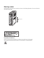
Warning Labels
Warning labels are pasted on the product as shown in the following illustration. Be sure to follow the
instructions given there.
Warning label
Precautions for Safe Use
Dispose of the product and batteries according to local ordinances as they apply.
Have qualified specialists properly dispose of used batteries as industrial waste.
Read and Understand this Manual
Please read and understand this manual before using the product. Please consult your OMRON
representative if you have any questions or comments.
Warranty and Limitations of Liability
WARRANTY
OMRON's exclusive warranty is that the products are free from defects in materials and workmanship for a
period of one year (or other period if specified) from date of sale by OMRON.
OMRON MAKES NO WARRANTY OR REPRESENTATION, EXPRESS OR IMPLIED, REGARDING NONINFRINGEMENT, MERCHANTABILITY, OR FITNESS FOR PARTICULAR PURPOSE OF THE
PRODUCTS. ANY BUYER OR USER ACKNOWLEDGES THAT THE BUYER OR USER ALONE HAS
DETERMINED THAT THE PRODUCTS WILL SUITABLY MEET THE REQUIREMENTS OF THEIR
INTENDED USE. OMRON DISCLAIMS ALL OTHER WARRANTIES, EXPRESS OR IMPLIED.
LIMITATIONS OF LIABILITY
OMRON SHALL NOT BE RESPONSIBLE FOR SPECIAL, INDIRECT, OR CONSEQUENTIAL DAMAGES,
LOSS OF PROFITS OR COMMERCIAL LOSS IN ANY WAY CONNECTED WITH THE PRODUCTS,
WHETHER SUCH CLAIM IS BASED ON CONTRACT, WARRANTY, NEGLIGENCE, OR STRICT
LIABILITY.
In no event shall the responsibility of OMRON for any act exceed the individual price of the product on which
liability is asserted.
IN NO EVENT SHALL OMRON BE RESPONSIBLE FOR WARRANTY, REPAIR, OR OTHER CLAIMS
REGARDING THE PRODUCTS UNLESS OMRON'S ANALYSIS CONFIRMS THAT THE PRODUCTS
WERE PROPERLY HANDLED, STORED, INSTALLED, AND MAINTAINED AND NOT SUBJECT TO
CONTAMINATION, ABUSE, MISUSE, OR INAPPROPRIATE MODIFICATION OR REPAIR.
Application Considerations
SUITABILITY FOR USE
OMRON shall not be responsible for conformity with any standards, codes, or regulations that apply to the
combination of products in the customer's application or use of the products.
At the customer's request, OMRON will provide applicable third party certification documents identifying
ratings and limitations of use that apply to the products. This information by itself is not sufficient for a
complete determination of the suitability of the products in combination with the end product, machine,
system, or other application or use.
The following are some examples of applications for which particular attention must be given. This is not
intended to be an exhaustive list of all possible uses of the products, nor is it intended to imply that the uses
listed may be suitable for the products:
• Outdoor use, uses involving potential chemical contamination or electrical interference, or conditions or
uses not described in this manual.
• Nuclear energy control systems, combustion systems, railroad systems, aviation systems, medical
equipment, amusement machines, vehicles, safety equipment, and installations subject to separate
industry or government regulations.
• Systems, machines, and equipment that could present a risk to life or property.
Please know and observe all prohibitions of use applicable to the products.
NEVER USE THE PRODUCTS FOR AN APPLICATION INVOLVING SERIOUS RISK TO LIFE OR
PROPERTY WITHOUT ENSURING THAT THE SYSTEM AS A WHOLE HAS BEEN DESIGNED TO
ADDRESS THE RISKS, AND THAT THE OMRON PRODUCTS ARE PROPERLY RATED AND
INSTALLED FOR THE INTENDED USE WITHIN THE OVERALL EQUIPMENT OR SYSTEM.
PROGRAMMABLE PRODUCTS
OMRON shall not be responsible for the user's programming of a programmable product, or any
consequence thereof.
Disclaimers
CHANGE IN SPECIFICATIONS
Product specifications and accessories may be changed at any time based on improvements and other
reasons.
It is our practice to change model numbers when published ratings or features are changed, or when
significant construction changes are made. However, some specifications of the products may be changed
without any notice. When in doubt, special model numbers may be assigned to fix or establish key
specifications for your application on your request. Please consult with your OMRON representative at any
time to confirm actual specifications of purchased products.
DIMENSIONS AND WEIGHTS
Dimensions and weights are nominal and are not to be used for manufacturing purposes, even when
tolerances are shown.
PERFORMANCE DATA
Performance data given in this manual is provided as a guide for the user in determining suitability and does
not constitute a warranty. It may represent the result of OMRON's test conditions, and the users must
correlate it to actual application requirements. Actual performance is subject to the OMRON Warranty and
Limitations of Liability.
ERRORS AND OMISSIONS
The information in this manual has been carefully checked and is believed to be accurate; however, no
responsibility is assumed for clerical, typographical, or proofreading errors, or omissions.
Table of Contents
Chapter 1. Introduction. . . . . . . . . . . . . . . . . . . . . . . . . . . . . . . . . . . .
1-1
1-2
1-3
1-4
1-5
1-1
Features. . . . . . . . . . . . . . . . . . . . . . . . . . . . . . . . . . . . . . . . . . . . . . . . . . . . . . . . . . . . . . . . . .
System Configuration . . . . . . . . . . . . . . . . . . . . . . . . . . . . . . . . . . . . . . . . . . . . . . . . . . . . . . .
Servo Driver Nomenclature . . . . . . . . . . . . . . . . . . . . . . . . . . . . . . . . . . . . . . . . . . . . . . . . . .
Applicable Standards and Models . . . . . . . . . . . . . . . . . . . . . . . . . . . . . . . . . . . . . . . . . . . . .
System Block Diagrams . . . . . . . . . . . . . . . . . . . . . . . . . . . . . . . . . . . . . . . . . . . . . . . . . . . . .
1-2
1-4
1-5
1-6
1-7
Chapter 2. Standard Models and Specifications. . . . . . . . . . . . . . . .
2-1
2-1
2-2
2-3
2-4
2-5
2-6
2-7
2-8
2-9
2-10
Standard Models . . . . . . . . . . . . . . . . . . . . . . . . . . . . . . . . . . . . . . . . . . . . . . . . . . . . . . . . . . .
Servo Driver and Servomotor Combinations . . . . . . . . . . . . . . . . . . . . . . . . . . . . . . . . . . . . .
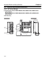
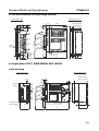
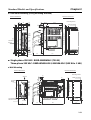
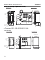
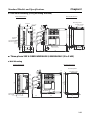
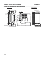
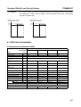
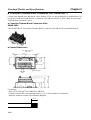
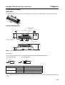
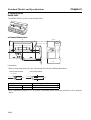
External and Mounted Dimensions . . . . . . . . . . . . . . . . . . . . . . . . . . . . . . . . . . . . . . . . . . . .
Servo Driver Specifications . . . . . . . . . . . . . . . . . . . . . . . . . . . . . . . . . . . . . . . . . . . . . . . . . .
Servomotor Specifications . . . . . . . . . . . . . . . . . . . . . . . . . . . . . . . . . . . . . . . . . . . . . . . . . . .
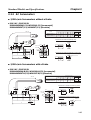
Cable and Connector Specifications. . . . . . . . . . . . . . . . . . . . . . . . . . . . . . . . . . . . . . . . . . . .
External Regeneration Resistor Specifications. . . . . . . . . . . . . . . . . . . . . . . . . . . . . . . . . . . .
Absolute Encoder Backup Battery Specifications . . . . . . . . . . . . . . . . . . . . . . . . . . . . . . . . .
Reactor Specifications . . . . . . . . . . . . . . . . . . . . . . . . . . . . . . . . . . . . . . . . . . . . . . . . . . . . . .
MECHATROLINK-II Repeater Specifications . . . . . . . . . . . . . . . . . . . . . . . . . . . . . . . . . . .
2-2
2-16
2-18
2-50
2-71
2-93
2-121
2-122
2-124
2-126
Chapter 3. System Design and Installation . . . . . . . . . . . . . . . . . . . .
3-1
3-1
3-2
3-3
3-4
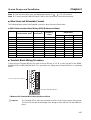
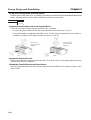
Installation Conditions . . . . . . . . . . . . . . . . . . . . . . . . . . . . . . . . . . . . . . . . . . . . . . . . . . . . . .
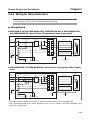
Wiring . . . . . . . . . . . . . . . . . . . . . . . . . . . . . . . . . . . . . . . . . . . . . . . . . . . . . . . . . . . . . . . . . . .
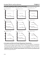
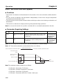
Regenerative Energy Absorption . . . . . . . . . . . . . . . . . . . . . . . . . . . . . . . . . . . . . . . . . . . . . .
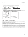
Adjustments and Dynamic Braking When Load Inertia Is Large . . . . . . . . . . . . . . . . . . . . .
3-3
3-8
3-32
3-39
Chapter 4. Operation. . . . . . . . . . . . . . . . . . . . . . . . . . . . . . . . . . . . . .
4-1
4-1
4-2
4-3
4-4
4-5
4-6
4-7
4-8
4-9
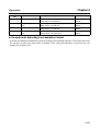
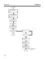
Operational Procedure . . . . . . . . . . . . . . . . . . . . . . . . . . . . . . . . . . . . . . . . . . . . . . . . . . . . . .
Preparing for Operation . . . . . . . . . . . . . . . . . . . . . . . . . . . . . . . . . . . . . . . . . . . . . . . . . . . . .
User Parameters . . . . . . . . . . . . . . . . . . . . . . . . . . . . . . . . . . . . . . . . . . . . . . . . . . . . . . . . . . .
Operation Functions . . . . . . . . . . . . . . . . . . . . . . . . . . . . . . . . . . . . . . . . . . . . . . . . . . . . . . . .
Trial Operation Procedure . . . . . . . . . . . . . . . . . . . . . . . . . . . . . . . . . . . . . . . . . . . . . . . . . . .
Making Adjustments . . . . . . . . . . . . . . . . . . . . . . . . . . . . . . . . . . . . . . . . . . . . . . . . . . . . . . .
Advanced Adjustment Functions . . . . . . . . . . . . . . . . . . . . . . . . . . . . . . . . . . . . . . . . . . . . . .
Using Displays . . . . . . . . . . . . . . . . . . . . . . . . . . . . . . . . . . . . . . . . . . . . . . . . . . . . . . . . . . . .
Using Monitor Output . . . . . . . . . . . . . . . . . . . . . . . . . . . . . . . . . . . . . . . . . . . . . . . . . . . . . .
4-3
4-4
4-8
4-75
4-96
4-98
4-103
4-130
4-132
Chapter 5. Troubleshooting . . . . . . . . . . . . . . . . . . . . . . . . . . . . . . . .
5-1
5-1
5-2
5-3
5-4
5-5
5-6
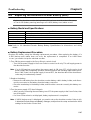
Measures when Trouble Occurs . . . . . . . . . . . . . . . . . . . . . . . . . . . . . . . . . . . . . . . . . . . . . . .
Alarms . . . . . . . . . . . . . . . . . . . . . . . . . . . . . . . . . . . . . . . . . . . . . . . . . . . . . . . . . . . . . . . . . .
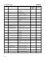
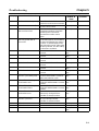
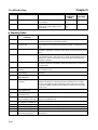
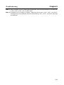
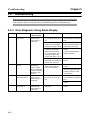
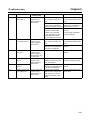
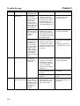
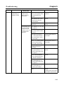
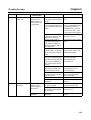
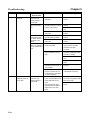
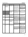
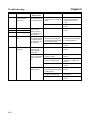
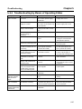
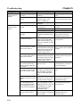
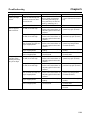
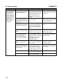
Troubleshooting . . . . . . . . . . . . . . . . . . . . . . . . . . . . . . . . . . . . . . . . . . . . . . . . . . . . . . . . . . .
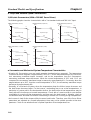
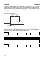
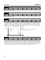
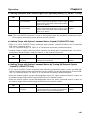
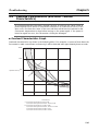
Overload Characteristics (Electronic Thermal Characteristics) . . . . . . . . . . . . . . . . . . . . . . .
Periodic Maintenance . . . . . . . . . . . . . . . . . . . . . . . . . . . . . . . . . . . . . . . . . . . . . . . . . . . . . . .
Replacing the Absolute Encoder Battery (ABS) . . . . . . . . . . . . . . . . . . . . . . . . . . . . . . . . . .
5-2
5-6
5-12
5-43
5-45
5-47
Table of Contents
Chapter 6. Appendix . . . . . . . . . . . . . . . . . . . . . . . . . . . . . . . . . . . . . .
6-1
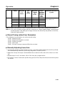
6-1 Connection Examples . . . . . . . . . . . . . . . . . . . . . . . . . . . . . . . . . . . . . . . . . . . . . . . . . . . . . . .
6-2 Parameter Setting Tables. . . . . . . . . . . . . . . . . . . . . . . . . . . . . . . . . . . . . . . . . . . . . . . . . . . . .
6-3 Restrictions . . . . . . . . . . . . . . . . . . . . . . . . . . . . . . . . . . . . . . . . . . . . . . . . . . . . . . . . . . . . . . .
6-2
6-3
6-21
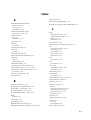
Index . . . . . . . . . . . . . . . . . . . . . . . . . . . . . . . . . . . . . . . . . . . . . . . . . . .
I-1
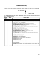
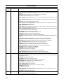
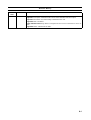
Revision History . . . . . . . . . . . . . . . . . . . . . . . . . . . . . . . . . . . . . . . . . .
R-1
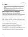
Chapter 1
Introduction
1-1
1-2
1-3
1-4
1-5
Features
System Configuration
Servo Driver Nomenclature
Applicable Standards and Models
System Block Diagrams
Introduction
1-1
Chapter 1
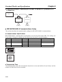
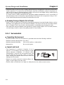
Features
OMNUC W-series AC Servo Drivers with built-in MECHATROLINK-II Communications
are designed specifically for use with the MECHATROLINK-II high-speed motion field
network.
Combining these Servo Drivers with MECHATROLINK-II-compatible Motion Control
Units (CS1W-MCH71 or CJ1W-MCH71) or Position Control Units (CJ1W-NCF71) is an
easy way to create a high-speed servo control system with a communications link
between the Servo Drivers and the Controllers.
■
Data Transfer by MECHATROLINK-II Communications
When a Servo Driver is combined with a MECHATROLINK-II-compatible Motion Control Unit (CS1WMCH71 or CJ1W-MCH71) or Position Control Unit (CJ1W-NCF71), all control data is transferred
between the Servo Driver and the Controller by means of data communications.
Control commands are transferred by means of data communications, so Servomotor performance is
not limited by control interface specifications, such as response frequencies for input pulses and
encoder feedback pulses. This allows the Servomotor to perform to its fullest capacity.
Moreover, system data control is simplified by having all Servo Driver parameters and monitor data
managed by the host controller.
■
Built-in Communications Interface
The MECHATROLINK-II communications interface has been built into the Servo Driver. In comparison with earlier W-series Servo Drivers, in which the MECHATROLINK-II Application Module is
installed, only 60% of the installation surface area is required. (for 200-V/100-W Servo Drivers). This
allows a great saving of space in the control panel.
■
W-series Servomotor Compatibility
A W-series Servomotor can be used as is, including the encoder cable and power cable, so the system can be upgraded without changing the structural design.
The W-series product line offers 3,000-r/min Servomotors (Cylinder-style: 50-W to 3-kW; Flat-style:
100-W to 1.5-kw), 1,000-r/min Servomotors (300-W to 2-kW), and 1,500-r/min Servomotors (450-W
to 1.8-kW). Also, IP67 (waterproof) Servomotors can be connected in the same way.
■
High-speed, High-precision Motion Control Capability
A less-deviation control function and a predictive control function are provided to shorten the Servomotor's settling time and achieving high tracking capability.
The W-series Servomotors handle motion control with increased speed and precision, including synchronous control in combination with CS1W-MCH71 or CJ1W-MCH71 Motion Control Units.
1-2
Introduction
■
Chapter 1
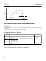
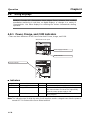
Regenerative Power Processing
In addition to the built-in regenerative power processing function using regeneration resistance,
external regeneration resistance can also be connected, allowing the W Series to be used for applications with high regenerative energy on vertical axes.
■
Conformity to Standards
The W Series conforms to EC Directives (both low-voltage and EMC) as well as to UL and cUL
requirements, thereby assisting the user in meeting required standards.
■
High-frequency Current Countermeasures
On Servo Drivers of 1 kW and above, a current reactor connection terminal is provided to assist the
user in controlling high-frequency current.
1-3
Chapter 1
Introduction
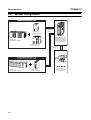
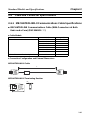
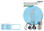
1-2
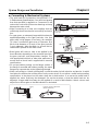
System Configuration
Controller (MECHATROLINK-II Type)
NCF71
MLK
RUN
ERC
ERH
ERM
67 8 9
DE0F1
AB C
UNIT
No.
2 34 5
MLK
CJ1W-NCF71
Position Control Unit
PA205R
SYSMAC
CJ1G-CPU44
POWER
PROGRAMMABLE
CONTROLLER
RUN
ERR/ALM
INH
PRPHL
COMM
OPEN
L1
MCPWR
BUSY
AC100-240V
INPUT
MECHATRO
LINK-II
L2/N
PERIPHERAL
RUN
OUTPUT
AC240V
DC24V
MCH71
PORT
R88D-WN@@@-ML2
OMNUC W-series AC
Servo Driver with builtin MECHATROLINK-II
Communications
6789
DE0F1
AB C
2 34 5
SYSMAC CJ1
Programmable Controller
CJ1W-MCH71
Motion Control Unit
MECHATRO
LINK-II
Controller (MECHATROLINK-II Type)
MCH71
RUN
ERC
ER1
ER2
SSI
ERH
ER3
ER4
MLK
UNIT
No.
T.B.
I/O
SYSMAC CS1
Programmable Controller
1-4
SSI
INC
ABS
MLK
CS1W-MCH71
Motion Control Unit
R88M-W@
OMNUC W-series
AC Servomotor
Chapter 1
Introduction
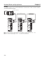
1-3
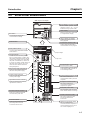
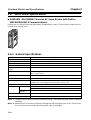
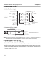
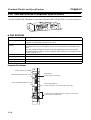
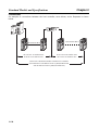
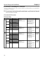
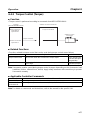
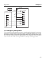
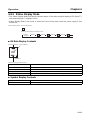
Servo Driver Nomenclature
With Top Cover Open
Analog Monitor Connector (CN5)
Motor rotation speeds, torque
command values, etc., can be
monitored using a special cable.
Panel Display
ON
1
2
3
Displays Servomotor status with
a 7-segment LED display.
4
DIP Switch
POWER
Used for MECHATROLINK-II
communications settings.
COM
Power Indicator (POWER)
Lit when the control power is
being supplied.
Model Number
Communications Indicator (COM)
Lit when MECHATROLINK-II
communications are in progress.
Rotary Switch (SW1)
R88D-WN01H-ML2
200V
AC SERVO DRIVER
Used for setting MECHATROLINK-II
node address.
POWER
COM
100W
Input voltage
Charge Indicator
SW1
C
N
6
9A
BC
F012
3 45 6
78
Lit when the main-circuit is powered.
Also, for Servo Drivers of 1 kW or less,
the indicator lights dimly when only the
control power supply is ON. Even after
the power is turned OFF, it remains lit
as long as an electric charge remains in
the main-circuit capacitor, so do not
touch the Servo Driver's terminals
during this period.
DE
CHARGE
Top cover
A/B
MECHATROLINK-II Communications
Connectors (CN6A, CN6B)
Main-circuit Power Terminals
C
N
3
These are the input terminals for
the main-circuit power supply.
Connect either a special cable for
a MECHATROLINK-II system or
a Terminating Resister.
Control Power Terminals
Personal Computer Connector (CN3)
This is the connector for
communications with a personal
computer.
These are input terminals for the
control power supply.
Regenerative Resistance Terminals
These are terminals for external
regenerative resistance.
These are ground terminals for
preventing electrical shock.
Connect to 100 Ω or less.
W
C
N
1
I/O Signal Connector (CN1)
This is the connector for
command input signals and
sequence I/O signals.
Nameplate (Side Panel)
The nameplate shows the Servo
Driver model number and ratings.
W
Ground Terminals
V
V
These are connector terminals
for Servomotor power line.
U
Servomotor Connector Terminals
U
C
N
2
C
N
4
Encoder Connector (CN2)
This is the connector for the
encoder provided for the
Servomotor.
Expansion Connector (CN4)
This is a supplementary
connector for future expansion. It
cannot presently be used, so do
not connect anything to it.
1-5
Chapter 1
Introduction
1-4
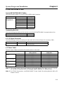
■
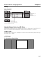
Applicable Standards and Models
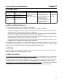
EC Directives
EC Directive
Product
Applicable standard
Low Voltage AC Servo Drivers EN50178
EMC
AC Servomotors IEC60034-8
EN60034-1, -5, -9
AC Servo Drivers EN55011 class A group 1
and AC Servomotors
EN61000-6-2
Remarks
Safety requirements for electrical equipment for
measurement, control, and laboratory use.
Rotating electrical machines.
Limits and methods for measuring radio disturbance characteristics of industrial, scientific, and
medical (ISM) radio-frequency equipment.
Electromagnetic compatibility generic immunity
standard in industrial environments
Note Installation under the conditions specified in 3-2-5 Wiring for Conformity to EMC Directives is
required to conform to EMC Directives.
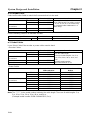
■
UL/cUL Standards
Standards
UL
cUL
1-6
Product
AC Servo Drivers
AC Servomotors
AC Servo Drivers
AC Servomotors
Applicable standard
UL508C
UL1004
cUL C22.2 No. 14
cUL C22.2 No. 100
File No.
E179149
E179189
E179149
E179189
Remarks
Power conversion equipment
Electric motors
Industrial control equipment
Motors and generators
Chapter 1
Introduction
1-5
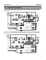
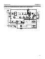
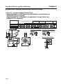
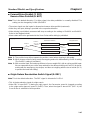
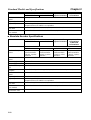
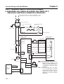
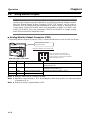
■
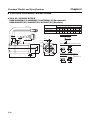
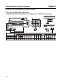
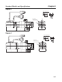
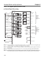
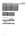
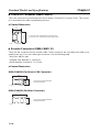
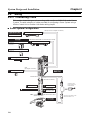
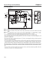
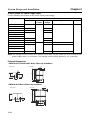
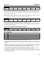
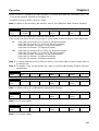
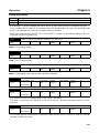
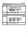
System Block Diagrams
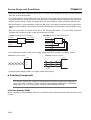
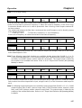
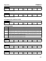
100 V AC: R88D-WNA5L-ML2/WN01L-ML2/-WL02L-ML2/-WN04L-ML2
Single-phase 100 to 115 V
+10%/−15% (50/60 Hz)
B1/
B2
Noise
filter
1KM
Servomotor
L1 Varistor
U
L2
V
CHARGE
W
M
Dynamic
brake circuit
Voltage
detection
Relay
drive
Voltage
detection
Gate
drive
Gate drive overcurrent protection
Temperature
detection
Current
detection
CN2
PG
CN10
L1C
Varistor
CN5
±5 V
15 V
Control
power
supply
L2C
Analog voltage
conversion
ASIC (PWM
control, etc.)
CN1
5V
±12 V
Power Power Open for
OFF ON
servo alarm
1KM
1KM
CPU (position,
speed calculations,
etc.)
1Ry
Surge
protector
Status indicator
Analog monitor
output
Encoder output
Control I/O
I/O
CN6A
I/F
MECHATROLINK-II
CN6B
CN3
Personal computer
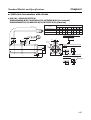
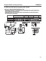
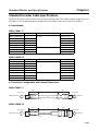
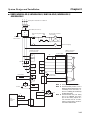
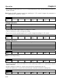
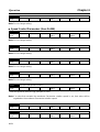
■
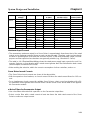
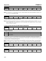
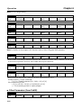
200 V AC: R88D-WNA5H-ML2/WN01H-ML2/-WL02H-ML2/-WN04H-ML2
Single-phase 200 to 230 V
+10%/−15% (50/60 Hz)
B1/
B2
Noise
filter
Servomotor
1KM
L1
Varistor
U
L2
V
CHARGE
W
M
Dynamic
brake circuit
Voltage
detection
Relay
drive
Voltage
detection
Gate
drive
Gate drive overcurrent protection
Temperature
detection
Current
detection
CN2
PG
CN10
L1C Varistor
Control
power
supply
L2C
CN5
±5 V
15 V
ASIC (PWM
control, etc.)
Analog voltage
conversion
CN1
Encoder output
5V
±12 V
Power Power Open for
OFF ON
servo alarm
1KM
1KM
1Ry
Surge
protector
Status indicator
CN3
Analog monitor
output
CPU (position,
speed calculations,
etc.)
I/O
Control I/O
CN6A
I/F
CN6B
MECHATROLINK-II
Personal computer
1-7
Chapter 1
Introduction
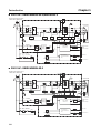
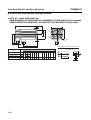
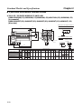
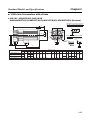
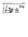
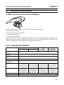
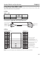
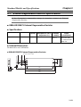
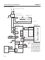
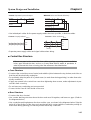
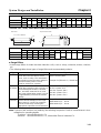
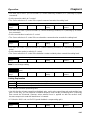
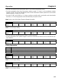
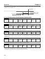
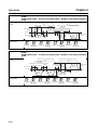
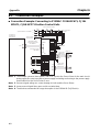
■
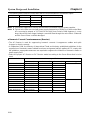
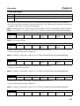
200 V AC: R88D-WN05H-ML2/WN10H-ML2
Three-phase 200 to 230 V
+10%/−15% (50/60 Hz)
B1/
B2
B3
Noise
filter
Servomotor
1KM
L1
Varistor
U
L2
V
CHARGE
L3
W
1
M
Dynamic
brake circuit
2
Voltage
detection
Relay
drive
Gate
drive
Voltage
detection
Gate drive overcurrent protection
Temperature
detection
Current
detection
CN2
PG
CN10
L1C Varistor
L2C
CN5
±5 V
15 V
Control
power
supply
Analog voltage
conversion
ASIC (PWM
control, etc.)
CN1
Encoder output
5V
±12 V
Power Power Open for
OFF ON
servo alarm
1KM
1Ry
CPU (position,
speed calculations,
etc.)
1KM
Surge
protector
Analog monitor
output
Status indicator
Control I/O
I/O
CN6A
I/F
MECHATROLINK-II
CN6B
CN3
Personal computer
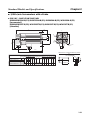
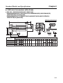
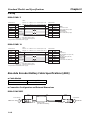
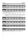
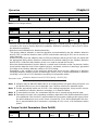
■
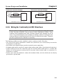
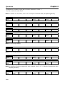
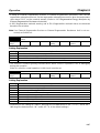
200 V AC: R88D-WN08H-ML2
Single-phase 200 to 230 V
+10%/−15% (50/60 Hz)
B1/
B2
B3
Noise
filter
Servomotor
1KM
L1
Varistor
U
L2
V
CHARGE
L3
W
1
M
Dynamic
brake circuit
2
Voltage
detection
Relay
drive
Gate
drive
Voltage
detection
Gate drive overcurrent protection
Temperature
detection
Current
detection
CN2
PG
CN10
L1C Varistor
CN5
±5 V
15 V
Control
power
supply
L2C
5V
±12 V
Power Power Open for
OFF ON
servo alarm
1KM
1Ry
1KM
Surge
protector
Status indicator
CN3
Personal computer
1-8
ASIC (PWM
control, etc.)
CPU (position,
speed calculations,
etc.)
Analog voltage
conversion
CN1
Analog monitor
output
Encoder output
Control I/O
I/O
CN6A
I/F
MECHATROLINK-II
CN6B
Chapter 1
Introduction
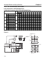
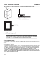
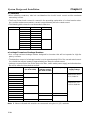
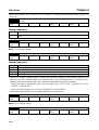
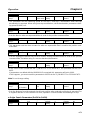
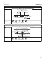
■
200 V AC: R88D-WN15H-ML2/-WN20H-ML2/-WN30H-ML2
Three-phase 200 to 230 V
+10%/−15% (50/60 Hz)
B1/
B2
B3
Noise
filter
Servomotor
1KM
L1
Varistor
U
L2
V
CHARGE
L3
W
1
M
Dynamic
brake circuit
2
Voltage
detection
Gate
drive
Voltage
detection
Relay
drive
Gate drive overcurrent protection
Current
detection
CN2
PG
CN10
L1C Varistor
L2C
Power Power Open for
OFF ON
servo alarm
1KM
ASIC (PWM
control, etc.)
Analog voltage
conversion
CN1
5V
±12 V
CPU (position,
speed calculations,
etc.)
1KM
1Ry
Surge
protector
CN5
±5 V
15 V
Control
power
supply
Status indicator
CN3
Analog monitor
output
Encoder output
Control I/O
I/O
CN6A
I/F
MECHATROLINK-II
CN6B
Personal computer
1-9
Introduction
1-10
Chapter 1
Chapter 2
Standard Models and
Specifications
2-1
2-2
2-3
2-4
2-5
2-6
2-7
2-8
2-9
2-10
Standard Models
Servo Driver and Servomotor Combinations
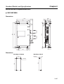
External and Mounted Dimensions
Servo Driver Specifications
Servomotor Specifications
Cable and Connector Specifications
External Regeneration Resistor Specifications
Absolute Encoder Backup Battery Specifications
Reactor Specifications
MECHATROLINK-II Repeater Specifications
Chapter 2
Standard Models and Specifications
2-1
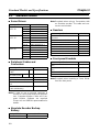
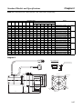
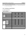
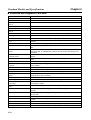
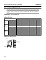
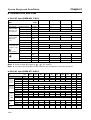
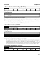
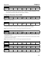
■
Standard Models
Servo Drivers
Specifications
Single-phase
50 W
100 V AC
100 W
200 W
400 W
Single-phase
50 W
200 V AC
100 W
200 W
400 W
750 W
Three-phase
500 W
200 V AC
1.0 kW
1.5 kW
2.0 kW
3.0 kW
Model
R88D-WNA5L-ML2
R88D-WN01L-ML2
R88D-WN02L-ML2
R88D-WN04L-ML2
R88D-WNA5H-ML2
R88D-WN01H-ML2
R88D-WN02H-ML2
R88D-WN04H-ML2
R88D-WN08H-ML2
R88D-WN05H-ML2
R88D-WN10H-ML2
R88D-WN15H-ML2
R88D-WN20H-ML2
R88D-WN30H-ML2
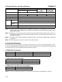
Note Required when using a Servomotor with
an absolute encoder. The cable and connector are included.
■
Specifications
For R88D-WNA5L-ML2/01L-ML2/
02H-ML2
For R88D-WN02L-ML2/04H-ML2
For R88D-WN04L-ML2/08H-ML2
For R88D-WNA5H-ML2/01H-ML2
For R88D-WT04H-ML2
For R88D-WN05H-ML2/10H-ML2
For R88D-WN15H-ML2/20H-ML2
For R88D-WN30H-ML2
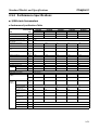
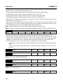
■
■
Peripheral Cables and
Connectors
Specifications
Analog Monitor Cable
1m
(CN5)
Computer Moni- DOS/V 2 m
tor Cable (CN3)
Control I/O Connector (CN1)
Encoder Connector (CN2)
Encoder Connector for Motor
End
Absolute Encoder Battery
Cable (with Battery)
Model
R88A-CMW001S
R88A-CCW002P2
R88A-CNW01C
R88A-CNW01R
R88A-CNW02R
R88A-CRWC0R3C
Note In order to use a personal computer to
monitor a Servo Driver and set its parameters, Computer Monitor Cable and Computer Monitor Software are required.
Please ask an OMRON representative for
details.
■
Absolute Encoder Backup
Battery
Specifications
1,000 mA·h, 3.6 V
2-2
Model
R88A-BAT01W
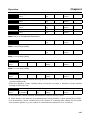
Reactors
Model
R88A-PX5053
R88A-PX5054
R88A-PX5056
R88A-PX5052
R88A-PX5069
R88A-PX5061
R88A-PX5060
R88A-PX5059
Front-panel Brackets
Specifications
For R88D-WNA5L-ML2 to 04LML2
For R88D-WNA5H-ML2 to 10HML2
For R88D-WN15H-ML2
For R88D-WN20H-ML2/30H-ML2
Model
R88A-TK05W
R88A-TK05W
R88A-TK06W
R88A-TK07W
Note Required when mounting a Servo Driver
from the front panel.
Chapter 2
Standard Models and Specifications
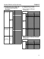
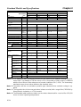
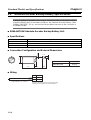
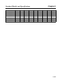
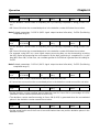
■
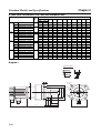
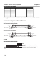
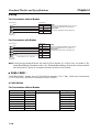
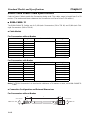
Standard Encoder Cables (for
Incremental and Absolute
Encoders)
Specifications
30 to
For 3,000-r/
min Servomo- 750 W
tors
1 to
3 kW
For 3,000-r/
min Flat-style
Servomotors
For 1,000-r/
min Servomotors
For 1,500-r/
min Servomotors
100 W
to
1.5 kW
300 W
to
2.0 kW
450 W
to
1.8 kW
3m
5m
10 m
15 m
20 m
30 m
40 m
50 m
3m
5m
10 m
15 m
20 m
30 m
40 m
50 m
3m
5m
10 m
15 m
20 m
30 m
40 m
50 m
3m
5m
10 m
15 m
20 m
30 m
40 m
50 m
Model
R88A-CRWA003C
R88A-CRWA005C
R88A-CRWA010C
R88A-CRWA015C
R88A-CRWA020C
R88A-CRWA030C
R88A-CRWA040C
R88A-CRWA050C
R88A-CRWB003N
R88A-CRWB005N
R88A-CRWB010N
R88A-CRWB015N
R88A-CRWB020N
R88A-CRWB030N
R88A-CRWB040N
R88A-CRWB050N
R88A-CRWA003C
R88A-CRWA005C
R88A-CRWA010C
R88A-CRWA015C
R88A-CRWA020C
R88A-CRWA030C
R88A-CRWA040C
R88A-CRWA050C
R88A-CRWB003N
R88A-CRWB005N
R88A-CRWB010N
R88A-CRWB015N
R88A-CRWB020N
R88A-CRWB030N
R88A-CRWB040N
R88A-CRWB050N
■
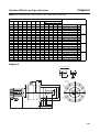
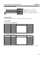
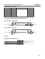
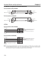
Standard Power Cable
●
Power Cable for 3,000-r/min
Servomotors
Specifications
30 to
750 W
1 to
2 kW
3 kW
3m
5m
10 m
15 m
20 m
30 m
40 m
50 m
3m
5m
10 m
15 m
20 m
30 m
40 m
50 m
3m
Model
Without brake
With brake
R88A-CAWA003S R88A-CAWA003B
R88A-CAWA005S R88A-CAWA005B
R88A-CAWA010S R88A-CAWA010B
R88A-CAWA015S R88A-CAWA015B
R88A-CAWA020S R88A-CAWA020B
R88A-CAWA030S R88A-CAWA030B
R88A-CAWA040S R88A-CAWA040B
R88A-CAWA050S R88A-CAWA050B
R88A-CAWC003S R88A-CAWC003B
R88A-CAWC005S R88A-CAWC005B
R88A-CAWC010S R88A-CAWC010B
R88A-CAWC015S R88A-CAWC015B
R88A-CAWC020S R88A-CAWC020B
R88A-CAWC030S R88A-CAWC030B
R88A-CAWC040S R88A-CAWC040B
R88A-CAWC050S R88A-CAWC050B
R88A-CAWD003S R88A-CAWD003B
5m
R88A-CAWD005S R88A-CAWD005B
10 m R88A-CAWD010S R88A-CAWD010B
15 m R88A-CAWD015S R88A-CAWD015B
20 m
30 m
40 m
50 m
●
R88A-CAWD020S
R88A-CAWD030S
R88A-CAWD040S
R88A-CAWD050S
R88A-CAWD020B
R88A-CAWD030B
R88A-CAWD040B
R88A-CAWD050B
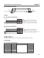
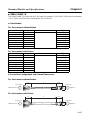
Power Cable for 3,000-r/min Flat-style
Servomotors
Specifications
100 to
750 W
3m
5m
10 m
15 m
20 m
30 m
40 m
50 m
Model
Without brake
With brake
R88A-CAWA003S R88A-CAWA003B
R88A-CAWA005S R88A-CAWA005B
R88A-CAWA010S R88A-CAWA010B
R88A-CAWA015S R88A-CAWA015B
R88A-CAWA020S R88A-CAWA020B
R88A-CAWA030S R88A-CAWA030B
R88A-CAWA040S R88A-CAWA040B
R88A-CAWA050S R88A-CAWA050B
2-3
Chapter 2
Standard Models and Specifications
Specifications
1.5 kW
●
3m
5m
10 m
15 m
20 m
30 m
40 m
50 m
Model
Without brake
With brake
R88A-CAWB003S R88A-CAWB003B
R88A-CAWB005S R88A-CAWB005B
R88A-CAWB010S R88A-CAWB010B
R88A-CAWB015S R88A-CAWB015B
R88A-CAWB020S R88A-CAWB020B
R88A-CAWB030S R88A-CAWB030B
R88A-CAWB040S R88A-CAWB040B
R88A-CAWB050S R88A-CAWB050B
Power Cable for 1,000-r/min
Servomotors
Specifications
300 to
900 W
1.2 to
2 kW
2-4
3m
5m
10 m
15 m
20 m
30 m
40 m
50 m
3m
5m
10 m
15 m
20 m
30 m
40 m
50 m
Model
Without brake
With brake
R88A-CAWC003S R88A-CAWC003B
R88A-CAWC005S R88A-CAWC005B
R88A-CAWC010S R88A-CAWC010B
R88A-CAWC015S R88A-CAWC015B
R88A-CAWC020S R88A-CAWC020B
R88A-CAWC030S R88A-CAWC030B
R88A-CAWC040S R88A-CAWC040B
R88A-CAWC050S R88A-CAWC050B
R88A-CAWD003S R88A-CAWD003B
R88A-CAWD005S R88A-CAWD005B
R88A-CAWD010S R88A-CAWD010B
R88A-CAWD015S R88A-CAWD015B
R88A-CAWD020S R88A-CAWD020B
R88A-CAWD030S R88A-CAWD030B
R88A-CAWD040S R88A-CAWD040B
R88A-CAWD050S R88A-CAWD050B
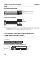
●
Power Cable for 1,500-r/min
Servomotors
Specifications
450 to
1.3 kW
1.8 kW
■
3m
5m
Model
Without brake
With brake
R88A-CAWC003S R88A-CAWC003B
R88A-CAWC005S R88A-CAWC005B
10 m
15 m
20 m
30 m
40 m
50 m
3m
5m
10 m
15 m
20 m
30 m
40 m
50 m
R88A-CAWC010S
R88A-CAWC015S
R88A-CAWC020S
R88A-CAWC030S
R88A-CAWC040S
R88A-CAWC050S
R88A-CAWD003S
R88A-CAWD005S
R88A-CAWD010S
R88A-CAWD015S
R88A-CAWD020S
R88A-CAWD030S
R88A-CAWD040S
R88A-CAWD050S
R88A-CAWC010B
R88A-CAWC015B
R88A-CAWC020B
R88A-CAWC030B
R88A-CAWC040B
R88A-CAWC050B
R88A-CAWD003B
R88A-CAWD005B
R88A-CAWD010B
R88A-CAWD015B
R88A-CAWD020B
R88A-CAWD030B
R88A-CAWD040B
R88A-CAWD050B
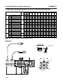
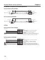
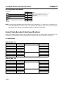
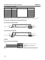
Encoder Cables for Robot
Cables (for Incremental and
Absolute Encoders)
Specifications
30 to
3m
For 3,000-r/
min Servomo- 750 W 5 m
tors
10 m
15 m
20 m
30 m
40 m
50 m
1 to
3m
3 kW
5m
10 m
15 m
20 m
30 m
40 m
50 m
Model
R88A-CRWA003CR
R88A-CRWA005CR
R88A-CRWA010CR
R88A-CRWA015CR
R88A-CRWA020CR
R88A-CRWA030CR
R88A-CRWA040CR
R88A-CRWA050CR
R88A-CRWB003NR
R88A-CRWB005NR
R88A-CRWB010NR
R88A-CRWB015NR
R88A-CRWB020NR
R88A-CRWB030NR
R88A-CRWB040NR
R88A-CRWB050NR
Chapter 2
Standard Models and Specifications
Specifications
100 W 3 m
For 3,000-r/
min Flat-style to
5m
Servomotors 1.5 kW
10 m
15 m
20 m
30 m
40 m
50 m
300 W 3 m
For 1,000-r/
min Servomo- to
5m
2.0 kW
tors
10 m
450 W
For 1,500-r/
15 m
min Servomo- to
1.8 kW 20 m
tors
30 m
40 m
50 m
■
●
Model
R88A-CRWA003CR
R88A-CRWA005CR
R88A-CRWA010CR
R88A-CRWA015CR
R88A-CRWA020CR
R88A-CRWA030CR
R88A-CRWA040CR
R88A-CRWA050CR
R88A-CRWB003NR
R88A-CRWB005NR
R88A-CRWB010NR
R88A-CRWB015NR
R88A-CRWB020NR
R88A-CRWB030NR
R88A-CRWB040NR
R88A-CRWB050NR
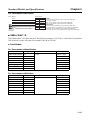
Specifications
3 kW
●
Power Cable for 3,000-r/min Flat-style
Servomotors
Specifications
100 to
750 W
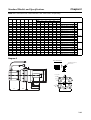
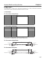
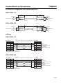
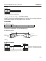
Power Cable for Robot Cables
Power Cable for 3,000-r/min
Servomotors
Specifications
30 to
750 W
1 to
2 kW
3m
5m
10 m
15 m
20 m
30 m
40 m
50 m
3m
5m
10 m
15 m
20 m
30 m
40 m
50 m
Model
Without brake
With brake
R88A-CAWA003SR R88A-CAWA003BR
R88A-CAWA005SR R88A-CAWA005BR
R88A-CAWA010SR R88A-CAWA010BR
R88A-CAWA015SR R88A-CAWA015BR
R88A-CAWA020SR R88A-CAWA020BR
R88A-CAWA030SR R88A-CAWA030BR
R88A-CAWA040SR R88A-CAWA040BR
R88A-CAWA050SR R88A-CAWA050BR
R88A-CAWC003SR R88A-CAWC003BR
R88A-CAWC005SR R88A-CAWC005BR
R88A-CAWC010SR R88A-CAWC010BR
R88A-CAWC015SR R88A-CAWC015BR
R88A-CAWC020SR R88A-CAWC020BR
R88A-CAWC030SR R88A-CAWC030BR
R88A-CAWC040SR R88A-CAWC040BR
R88A-CAWC050SR R88A-CAWC050BR
3m
5m
10 m
15 m
20 m
30 m
40 m
50 m
1.5 kW
●
Model
Without brake
With brake
R88A-CAWD003SR R88A-CAWD003BR
R88A-CAWD005SR R88A-CAWD005BR
R88A-CAWD010SR R88A-CAWD010BR
R88A-CAWD015SR R88A-CAWD015BR
R88A-CAWD020SR R88A-CAWD020BR
R88A-CAWD030SR R88A-CAWD030BR
R88A-CAWD040SR R88A-CAWD040BR
R88A-CAWD050SR R88A-CAWD050BR
3m
5m
10 m
15 m
20 m
30 m
40 m
50 m
3m
5m
10 m
15 m
20 m
30 m
40 m
50 m
Model
Without brake
With brake
R88A-CAWA003SR R88A-CAWA003BR
R88A-CAWA005SR R88A-CAWA005BR
R88A-CAWA010SR R88A-CAWA010BR
R88A-CAWA015SR R88A-CAWA015BR
R88A-CAWA020SR R88A-CAWA020BR
R88A-CAWA030SR R88A-CAWA030BR
R88A-CAWA040SR R88A-CAWA040BR
R88A-CAWA050SR R88A-CAWA050BR
R88A-CAWB003SR R88A-CAWB003BR
R88A-CAWB005SR R88A-CAWB005BR
R88A-CAWB010SR R88A-CAWB010BR
R88A-CAWB015SR R88A-CAWB015BR
R88A-CAWB020SR R88A-CAWB020BR
R88A-CAWB030SR R88A-CAWB030BR
R88A-CAWB040SR R88A-CAWB040BR
R88A-CAWB050SR R88A-CAWB050BR
Power Cable for 1,000-r/min
Servomotors
Specifications
300 to
900 W
3m
5m
10 m
15 m
20 m
30 m
40 m
50 m
Model
Without brake
With brake
R88A-CAWC003SR R88A-CAWC003BR
R88A-CAWC005SR R88A-CAWC005BR
R88A-CAWC010SR R88A-CAWC010BR
R88A-CAWC015SR R88A-CAWC015BR
R88A-CAWC020SR R88A-CAWC020BR
R88A-CAWC030SR R88A-CAWC030BR
R88A-CAWC040SR R88A-CAWC040BR
R88A-CAWC050SR R88A-CAWC050BR
2-5
Standard Models and Specifications
Specifications
1.2 to
2 kW
●
3m
5m
10 m
15 m
20 m
30 m
40 m
50 m
Model
Without brake
With brake
R88A-CAWD003SR R88A-CAWD003BR
R88A-CAWD005SR R88A-CAWD005BR
R88A-CAWD010SR R88A-CAWD010BR
R88A-CAWD015SR R88A-CAWD015BR
R88A-CAWD020SR R88A-CAWD020BR
R88A-CAWD030SR R88A-CAWD030BR
R88A-CAWD040SR R88A-CAWD040BR
R88A-CAWD050SR R88A-CAWD050BR
Power Cable for 1,500-r/min
Servomotors
Specifications
450 to
1.3 kW
1.8 kW
2-6
3m
5m
10 m
15 m
20 m
30 m
40 m
50 m
3m
5m
10 m
15 m
20 m
30 m
40 m
50 m
Model
Without brake
With brake
R88A-CAWC003SR R88A-CAWC003BR
R88A-CAWC005SR R88A-CAWC005BR
R88A-CAWC010SR R88A-CAWC010BR
R88A-CAWC015SR R88A-CAWC015BR
R88A-CAWC020SR R88A-CAWC020BR
R88A-CAWC030SR R88A-CAWC030BR
R88A-CAWC040SR R88A-CAWC040BR
R88A-CAWC050SR R88A-CAWC050BR
R88A-CAWD003SR R88A-CAWD003BR
R88A-CAWD005SR R88A-CAWD005BR
R88A-CAWD010SR R88A-CAWD010BR
R88A-CAWD015SR R88A-CAWD015BR
R88A-CAWD020SR R88A-CAWD020BR
R88A-CAWD030SR R88A-CAWD030BR
R88A-CAWD040SR R88A-CAWD040BR
R88A-CAWD050SR R88A-CAWD050BR
Chapter 2
Chapter 2
Standard Models and Specifications
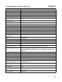
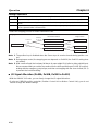
■
Servomotors
Specifications
Model
With incremental encoder
Straight shaft without
key
●
With
brake
Straight shaft with key
200 V 50 W
R88M-W05030H
R88M-W05030H-S1
R88M-W05030T
R88M-W05030T-S1
100 W
R88M-W10030H
R88M-W10030H-S1
R88M-W10030T
R88M-W10030T-S1
200 W
R88M-W20030H
R88M-W20030H-S1
R88M-W20030T
R88M-W20030T-S1
400 W
R88M-W40030H
R88M-W40030H-S1
R88M-W40030T
R88M-W40030T-S1
750 W
R88M-W75030H
R88M-W75030H-S1
R88M-W75030T
R88M-W75030T-S1
1 kW
R88M-W1K030H
R88M-W1K030H-S2
R88M-W1K030T
R88M-W1K030T-S2
1.5 kW R88M-W1K530H
R88M-W1K530H-S2
R88M-W1K530T
R88M-W1K530T-S2
2 kW
R88M-W2K030H
R88M-W2K030H-S2
R88M-W2K030T
R88M-W2K030T-S2
3 kW
R88M-W3K030H
R88M-W3K030H-S2
R88M-W3K030T
R88M-W3K030T-S2
R88M-W05030H-B
R88M-W05030H-BS1
R88M-W05030T-B
R88M-W05030T-BS1
100 W
R88M-W10030H-B
R88M-W10030H-BS1
R88M-W10030T-B
R88M-W10030T-BS1
200 W
R88M-W20030H-B
R88M-W20030H-BS1
R88M-W20030T-B
R88M-W20030T-BS1
400 W
R88M-W40030H-B
R88M-W40030H-BS1
R88M-W40030T-B
R88M-W40030T-BS1
750 W
R88M-W75030H-B
R88M-W75030H-BS1
R88M-W75030T-B
R88M-W75030T-BS1
1 kW
R88M-W1K030T-BS2
200 V 50 W
R88M-W1K030H-B
R88M-W1K030H-BS2
R88M-W1K030T-B
1.5 kW R88M-W1K530H-B
R88M-W1K530H-BS2
R88M-W1K530T-B
R88M-W1K530T-BS2
2 kW
R88M-W2K030H-B
R88M-W2K030H-BS2
R88M-W2K030T-B
R88M-W2K030T-BS2
3 kW
R88M-W3K030H-B
R88M-W3K030H-BS2
R88M-W3K030T-B
R88M-W3K030T-BS2
3,000-r/min Flat-style Servomotors
Without
brake
With
brake
●
With absolute encoder
Straight shaft without
key
3,000-r/min Servomotors
Without
brake
●
Straight shaft with key
200 V 100 W
R88M-WP10030H
R88M-WP10030H-S1
R88M-WP10030T
R88M-WP10030T-S1
200 W
R88M-WP20030H
R88M-WP20030H-S1
R88M-WP20030T
R88M-WP20030T-S1
400 W
R88M-WP40030H
R88M-WP40030H-S1
R88M-WP40030T
R88M-WP40030T-S1
750 W
R88M-WP75030H
R88M-WP75030H-S1
R88M-WP75030T
R88M-WP75030T-S1
1.5 kW R88M-WP1K530H
R88M-WP1K530H-S1
R88M-WP1K530T
R88M-WP1K530T-S1
200 V 100 W
R88M-WP10030H-B
R88M-WP10030H-BS1
R88M-WP10030T-B
R88M-WP10030T-BS1
200 W
R88M-WP20030H-B
R88M-WP20030H-BS1
R88M-WP20030T-B
R88M-WP20030T-BS1
400 W
R88M-WP40030H-B
R88M-WP40030H-BS1
R88M-WP40030T-B
R88M-WP40030T-BS1
750 W
R88M-WP75030H-B
R88M-WP75030H-BS1
R88M-WP75030T-B
R88M-WP75030T-BS1
1.5 kW R88M-WP1K530H-B
R88M-WP1K530H-BS1
R88M-WP1K530T-B
R88M-WP1K530T-BS1
1,000-r/min Servomotors
Without
brake
With
brake
200 V 300 W
R88M-W30010H
R88M-W30010H-S2
R88M-W30010T
R88M-W30010T-S2
600 W
R88M-W60010H
R88M-W60010H-S2
R88M-W60010T
R88M-W60010T-S2
900 W
R88M-W90010T-S2
R88M-W90010H
R88M-W90010H-S2
R88M-W90010T
1.2 kW R88M-W1K210H
R88M-W1K210H-S2
R88M-W1K210T
R88M-W1K210T-S2
2 kW
R88M-W2K010H
R88M-W2K010H-S2
R88M-W2K010T
R88M-W2K010T-S2
200 V 300 W
R88M-W30010H-B
R88M-W30010H-BS2
R88M-W30010T-B
R88M-W30010T-BS2
600 W
R88M-W60010H-B
R88M-W60010H-BS2
R88M-W60010T-B
R88M-W60010T-BS2
900 W
R88M-W90010H-B
R88M-W90010H-BS2
R88M-W90010T-B
R88M-W90010T-BS2
1.2 kW R88M-W1K210H-B
R88M-W1K210H-BS2
R88M-W1K210T-B
R88M-W1K210T-BS2
2 kW
R88M-W2K010H-BS2
R88M-W2K010T-B
R88M-W2K010T-BS2
R88M-W2K010H-B
2-7
Chapter 2
Standard Models and Specifications
●
1,500-r/min Servomotors
Without
brake
With
brake
■
200 V 450 W
---
---
R88M-W45015T
R88M-W45015T-S2
850 W
---
---
R88M-W85015T
R88M-W85015T-S2
1.3 kW ---
---
R88M-W1K315T
R88M-W1K315T-S2
1.8 kW ---
---
R88M-W1K815T
R88M-W1K815T-S2
200 V 450 W
---
---
R88M-W45015T-B
R88M-W45015T-BS2
850 W
---
---
R88M-W85015T-B
R88M-W85015T-BS2
1.3 kW ---
---
R88M-W1K315T-B
R88M-W1K315T-BS2
1.8 kW ---
---
R88M-W1K815T-B
R88M-W1K815T-BS2
IP67 (Waterproof) Servomotors
Specifications
Model
With incremental encoder
Straight shaft without
key
●
With
brake
Straight shaft with key
200 V 1 kW
R88M-W1K030H-O
R88M-W1K030H-OS2
R88M-W1K030T-O
R88M-W1K030T-OS2
1.5 kW R88M-W1K530H-O
R88M-W1K530H-OS2
R88M-W1K530T-O
R88M-W1K530T-OS2
2 kW
R88M-W2K030H-O
R88M-W2K030H-OS2
R88M-W2K030T-O
R88M-W2K030T-OS2
3 kW
R88M-W3K030H-O
R88M-W3K030H-OS2
R88M-W3K030T-O
R88M-W3K030T-OS2
R88M-W1K030H-BO
R88M-W1K030H-BOS2
R88M-W1K030T-BO
R88M-W1K030T-BOS2
1.5 kW R88M-W1K530H-BO
R88M-W1K530H-BOS2
R88M-W1K530T-BO
R88M-W1K530T-BOS2
2 kW
R88M-W2K030H-BO
R88M-W2K030H-BOS2
R88M-W2K030T-BO
R88M-W2K030T-BOS2
3 kW
R88M-W3K030H-BO
R88M-W3K030H-BOS2
R88M-W3K030T-BO
R88M-W3K030T-BOS2
200 V 1 kW
3,000-r/min Flat-style Servomotors
Without
brake
With
brake
●
Straight shaft without
key
3,000-r/min Servomotors
Without
brake
●
Straight shaft with key
With absolute encoder
200 V 100 W
R88M-WP10030H-W
R88M-WP10030H-WS1
R88M-WP10030T-W
R88M-WP10030T-WS1
200 W
R88M-WP20030H-W
R88M-WP20030H-WS1
R88M-WP20030T-W
R88M-WP20030T-WS1
400 W
R88M-WP40030H-W
R88M-WP40030H-WS1
R88M-WP40030T-W
R88M-WP40030T-WS1
750 W
R88M-WP75030H-W
R88M-WP75030H-WS1
R88M-WP75030T-W
R88M-WP75030T-WS1
1.5 kW R88M-WP1K530H-W
R88M-WP1K530H-WS1
R88M-WP1K530T-W
R88M-WP1K530T-WS1
200 V 100 W
R88M-WP10030H-BW
R88M-WP10030H-BWS1 R88M-WP10030T-BW
R88M-WP10030T-BWS1
200 W
R88M-WP20030H-BW
R88M-WP20030H-BWS1 R88M-WP20030T-BW
R88M-WP20030T-BWS1
400 W
R88M-WP40030H-BW
R88M-WP40030H-BWS1 R88M-WP40030T-BW
R88M-WP40030T-BWS1
750 W
R88M-WP75030H-BW
R88M-WP75030H-BWS1 R88M-WP75030T-BW
R88M-WP75030T-BWS1
1.5 kW R88M-WP1K530H-BW
R88M-WP1K530H-BWS1 R88M-WP1K530T-BW
R88M-WP1K530T-BWS1
1,000-r/min Servomotors
Without
brake
With
brake
2-8
200 V 300 W
R88M-W30010H-O
R88M-W30010H-OS2
R88M-W30010T-O
R88M-W30010T-OS2
600 W
R88M-W60010H-O
R88M-W60010H-OS2
R88M-W60010T-O
R88M-W60010T-OS2
900 W
R88M-W90010H-O
R88M-W90010H-OS2
R88M-W90010T-O
R88M-W90010T-OS2
1.2 kW R88M-W1K210H-O
R88M-W1K210H-OS2
R88M-W1K210T-O
R88M-W1K210T-OS2
2 kW
R88M-W2K010H-O
R88M-W2K010H-OS2
R88M-W2K010T-O
R88M-W2K010T-OS2
200 V 300 W
R88M-W30010H-BO
R88M-W30010H-BOS2
R88M-W30010T-BO
R88M-W30010T-BOS2
600 W
R88M-W60010H-BO
R88M-W60010H-BOS2
R88M-W60010T-BO
R88M-W60010T-BOS2
900 W
R88M-W90010H-BO
R88M-W90010H-BOS2
R88M-W90010T-BO
R88M-W90010T-BOS2
1.2 kW R88M-W1K210H-BO
R88M-W1K210H-BOS2
R88M-W1K210T-BO
R88M-W1K210T-BOS2
2 kW
R88M-W2K010H-BOS2
R88M-W2K010T-BO
R88M-W2K010T-BOS2
R88M-W2K010H-BO
Chapter 2
Standard Models and Specifications
●
1,500-r/min Servomotors
Without
brake
With
brake
■
●
200 V 450 W
---
---
R88M-W45015TO
R88M-W45015T-OS2
850 W
---
---
R88M-W85015TO
R88M-W85015T-OS2
1.3 kW ---
---
R88M-W1K315TO
R88M-W1K315T-OS2
1.8 kW ---
---
R88M-W1K815TO
R88M-W1K815T-OS2
200 V 450 W
---
---
R88M-W45015T-BO
R88M-W45015T-BOS2
850 W
---
---
R88M-W85015T-BO
R88M-W85015T-BOS2
1.3 kW ---
---
R88M-W1K315T-BO
R88M-W1K315T-BOS2
1.8 kW ---
---
R88M-W1K815T-BO
R88M-W1K815T-BOS2
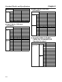
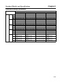
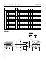
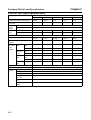
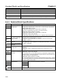
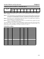
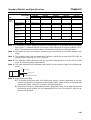
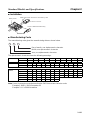
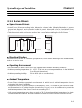
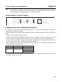
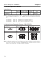
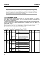
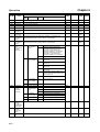
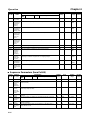
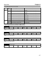
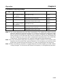
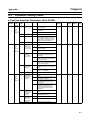
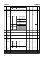
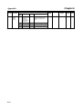
Servomotors with Gears
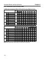
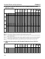
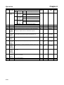
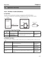
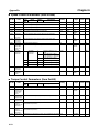
Combination Table for Servomotors with Standard Gears
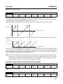
Standard Gears are highly accurate gears, with a maximum backlash of 3 degrees. The standard
shaft is a straight shaft with a key. (Models without keys can also be manufactured for 3,000-r/min
motors from 30 to 750 W and for 3,000-r/min flat-style motors. Models without keys have a suffix of G@@B.)
Note A check mark in a box indicates that the two models can be combined. If the box is unchecked,
then the models cannot be combined.
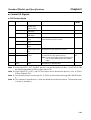
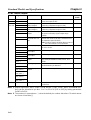
3,000-r/min Servomotors
Specifications
200 V 50 W
Basic model
Gear (deceleration rate)
1/5
1/9
1/11
1/20
1/21
1/29
1/33
1/45
-G05BJ
-G09BJ
-G11BJ
-G20BJ
-G21BJ
-G29BJ
-G33BJ
-G45BJ
R88M-W05030H/T
Yes
Yes
Yes
100 W
R88M-W10030H/T
Yes
Yes
Yes
Yes
Yes
200 W
R88M-W20030H/T
Yes
Yes
Yes
Yes
400 W
R88M-W40030H/T
Yes
Yes
Yes
Yes
750 W
R88M-W75030H/T
Yes
Yes
Yes
1 kW
R88M-W1K030H/T
Yes
Yes
Yes
Yes
Yes
1.5 kW R88M-W1K530H/T
Yes
Yes
Yes
Yes
Yes
2 kW
R88M-W2K030H/T
Yes
Yes
Yes
Yes
Yes
3 kW
R88M-W3K030H/T
Yes
Yes
Yes
Yes
Yes
Yes
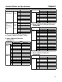
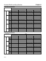
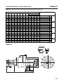
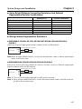
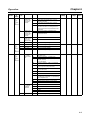
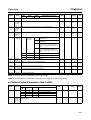
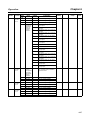
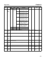
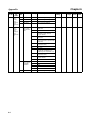
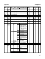
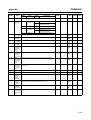
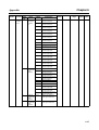
3,000-r/min Flat-style Servomotors
Specifications
Basic model
Gear (deceleration rate)
1/5
1/9
1/11
1/20
1/21
1/29
1/33
1/45
-G05BJ
-G09BJ
-G11BJ
-G20BJ
-G21BJ
-G29BJ
-G33BJ
-G45BJ
200 V 100 W
R88M-WP10030H/T
Yes
Yes
Yes
Yes
200 W
R88M-WP20030H/T
Yes
Yes
Yes
Yes
400 W
R88M-WP40030H/T
Yes
Yes
Yes
Yes
750 W
R88M-WP75030H/T
Yes
Yes
Yes
Yes
1.5 kW R88M-WP1K530H/T
Yes
Yes
Yes
Yes
2-9
Chapter 2
Standard Models and Specifications
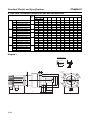
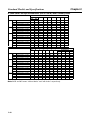
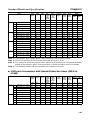
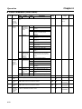
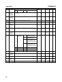
1,000-r/min Servomotors
Specifications
Basic model
Gear (deceleration rate)
1/5
1/9
1/11
1/20
1/21
1/29
1/33
1/45
-G05BJ
-G09BJ
-G11BJ
-G20BJ
-G21BJ
-G29BJ
-G33BJ
-G45BJ
200 V 300 W
R88M-W30010H/T
Yes
Yes
Yes
Yes
Yes
600 W
R88M-W60010H/T
Yes
Yes
Yes
Yes
Yes
900 W
R88M-W90010H/T
Yes
Yes
Yes
Yes
Yes
1.2 kW R88M-W1K210H/T
Yes
Yes
Yes
Yes
Yes
2 kW
Yes
Yes
Yes
R88M-W2K010H/T
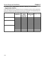
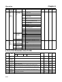
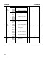
1,500-r/min Servomotors
Specifications
Basic model
Gear (deceleration rate)
1/5
1/9
1/11
1/20
1/21
1/29
1/33
1/45
-G05BJ
-G09BJ
-G11BJ
-G20BJ
-G21BJ
-G29BJ
-G33BJ
-G45BJ
200 V 450 W
R88M-W45015T
Yes
Yes
Yes
Yes
Yes
850 W
R88M-W85015T
Yes
Yes
Yes
Yes
Yes
1.3 kW R88M-W1K315T
Yes
Yes
Yes
Yes
Yes
1.8 kW R88M-W1K815T
Yes
Yes
Yes
Yes
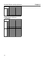
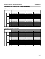
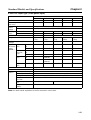
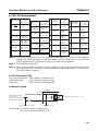
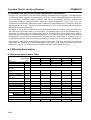
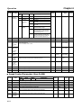
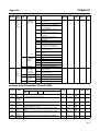
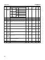
■
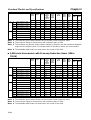
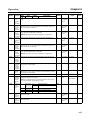
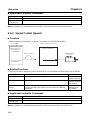
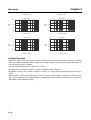
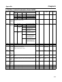
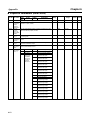
Combination Table for Servomotors with Economy Gears
Economy Gears are low-cost gears, with a maximum backlash of 45 degrees. The shaft is a straight
shaft with key. Models without keys are not available.
Note 1. The 1,000-r/min and 1,500-r/min Servomotors cannot be combined with Economy Gears.
Note 2. A check mark in a box indicates that the two models can be combined. If the box is unchecked, then the models cannot be combined.
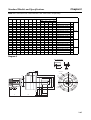
3,000-r/min Servomotors
Specifications
200 V 50 W
Basic model
1/5
1/9
1/15
1/25
-G05CJ
-G09CJ
-G15C
-G25CJ
R88M-W05030H/T
100 W
R88M-W10030H/T
Yes
Yes
Yes
Yes
200 W
R88M-W20030H/T
Yes
Yes
Yes
Yes
400 W
R88M-W40030H/T
Yes
Yes
Yes
Yes
750 W
R88M-W75030H/T
Yes
Yes
Yes
Yes
1 kW
R88M-W1K030H/T
1.5 kW R88M-W1K530H/T
2-10
Gear (deceleration rate)
2 kW
R88M-W2K030H/T
3 kW
R88M-W3K030H/T
Chapter 2
Standard Models and Specifications
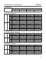
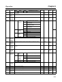
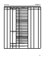
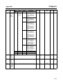
3,000-r/min Flat-style Servomotors
Specifications
Basic model
Gear (deceleration rate)
1/5
1/9
1/15
1/25
-G05CJ
-G09CJ
-G15C
-G25CJ
200 V 100 W
R88M-WP10030H/T
Yes
Yes
Yes
Yes
200 W
R88M-WP20030H/T
Yes
Yes
Yes
Yes
400 W
R88M-WP40030H/T
Yes
Yes
Yes
Yes
750 W
R88M-WP75030H/T
Yes
Yes
Yes
Yes
1.5 kW R88M-WP1K530H/T
2-11
Chapter 2
Standard Models and Specifications
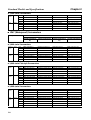
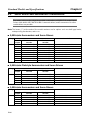
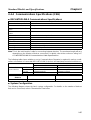
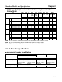
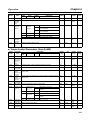
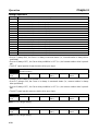
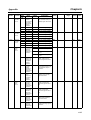
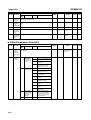
●
Servomotors with Standard Gears (Straight Shaft with Key)
3,000-r/min Servomotors
Specifications
Model
With incremental encoder
200 V 50 W
100 W
200 W
400 W
750 W
1 kW
With brake
R88M-W05030H-G05BJ
R88M-W05030H-BG05BJ
1/9
R88M-W05030H-G09BJ
R88M-W05030H-BG09BJ
R88M-W05030T-G09BJ
R88M-W05030T-BG09BJ
1/21
R88M-W05030H-G21BJ
R88M-W05030H-BG21BJ
R88M-W05030T-G21BJ
R88M-W05030T-BG21BJ
1/33
R88M-W05030H-G33BJ
R88M-W05030H-BG33BJ
R88M-W05030T-G33BJ
R88M-W05030T-BG33BJ
1/5
R88M-W10030H-G05BJ
R88M-W10030H-BG05BJ
R88M-W10030T-G05BJ
R88M-W10030T-BG05BJ
1/11
R88M-W10030H-G11BJ
R88M-W10030H-BG11BJ
R88M-W10030T-G11BJ
R88M-W10030T-BG11BJ
1/21
R88M-W10030H-G21BJ
R88M-W10030H-BG21BJ
R88M-W10030T-G21BJ
R88M-W10030T-BG21BJ
1/33
R88M-W10030H-G33BJ
R88M-W10030H-BG33BJ
R88M-W10030T-G33BJ
R88M-W10030T-BG33BJ
1/5
R88M-W20030H-G05BJ
R88M-W20030H-BG05BJ
R88M-W20030T-G05BJ
R88M-W20030T-BG05BJ
1/11
R88M-W20030H-G11BJ
R88M-W20030H-BG11BJ
R88M-W20030T-G11BJ
R88M-W20030T-BG11BJ
1/21
R88M-W20030H-G21BJ
R88M-W20030H-BG21BJ
R88M-W20030T-G21BJ
R88M-W20030T-BG21BJ
1/33
R88M-W20030H-G33BJ
R88M-W20030H-BG33BJ
R88M-W20030T-G33BJ
R88M-W20030T-BG33BJ
1/5
R88M-W40030H-G05BJ
R88M-W40030H-BG05BJ
R88M-W40030T-G05BJ
R88M-W40030T-BG05BJ
1/11
R88M-W40030H-G11BJ
R88M-W40030H-BG11BJ
R88M-W40030T-G11BJ
R88M-W40030T-BG11BJ
1/21
R88M-W40030H-G21BJ
R88M-W40030H-BG21BJ
R88M-W40030T-G21BJ
R88M-W40030T-BG21BJ
1/33
R88M-W40030H-G33BJ
R88M-W40030H-BG33BJ
R88M-W40030T-G33BJ
R88M-W40030T-BG33BJ
1/5
R88M-W75030H-G05BJ
R88M-W75030H-BG05BJ
R88M-W75030T-G05BJ
R88M-W75030T-BG05BJ
1/11
R88M-W75030H-G11BJ
R88M-W75030H-BG11BJ
R88M-W75030T-G11BJ
R88M-W75030T-BG11BJ
1/21
R88M-W75030H-G21BJ
R88M-W75030H-BG21BJ
R88M-W75030T-G21BJ
R88M-W75030T-BG21BJ
1/33
R88M-W75030H-G33BJ
R88M-W75030H-BG33BJ
R88M-W75030T-G33BJ
R88M-W75030T-BG33BJ
1/5
R88M-W1K030H-G05BJ
R88M-W1K030H-BG05BJ R88M-W1K030T-G05BJ
R88M-W1K030T-BG05BJ
1/5
Without brake
R88M-W05030T-G05BJ
With brake
R88M-W05030T-BG05BJ
1/9
R88M-W1K030H-G09BJ
R88M-W1K030H-BG09BJ R88M-W1K030T-G09BJ
R88M-W1K030T-BG09BJ
1/20
R88M-W1K030H-G20BJ
R88M-W1K030H-BG20BJ R88M-W1K030T-G20BJ
R88M-W1K030T-BG20BJ
1/29
R88M-W1K030H-G29BJ
R88M-W1K030H-BG29BJ R88M-W1K030T-G29BJ
R88M-W1K030T-BG29BJ
1/45
R88M-W1K030H-G45BJ
R88M-W1K030H-BG45BJ R88M-W1K030T-G45BJ
R88M-W1K030T-BG45BJ
1.5 kW 1/5
R88M-W1K530H-G05BJ
R88M-W1K530H-BG05BJ R88M-W1K530T-G05BJ
R88M-W1K530T-BG05BJ
1/9
R88M-W1K530H-G09BJ
R88M-W1K530H-BG09BJ R88M-W1K530T-G09BJ
R88M-W1K530T-BG09BJ
1/20
R88M-W1K530H-G20BJ
R88M-W1K530H-BG20BJ R88M-W1K530T-G20BJ
R88M-W1K530T-BG20BJ
1/29
R88M-W1K530H-G29BJ
R88M-W1K530H-BG29BJ R88M-W1K530T-G29BJ
R88M-W1K530T-BG29BJ
1/45
R88M-W1K530H-G45BJ
R88M-W1K530H-BG45BJ R88M-W1K530T-G45BJ
R88M-W1K530T-BG45BJ
1/5
R88M-W2K030H-G05BJ
R88M-W2K030H-BG05BJ R88M-W2K030T-G05BJ
R88M-W2K030T-BG05BJ
1/9
R88M-W2K030H-G09BJ
R88M-W2K030H-BG09BJ R88M-W2K030T-G09BJ
R88M-W2K030T-BG09BJ
1/20
R88M-W2K030H-G20BJ
R88M-W2K030H-BG20BJ R88M-W2K030T-G20BJ
R88M-W2K030T-BG20BJ
1/29
R88M-W2K030H-G29BJ
R88M-W2K030H-BG29BJ R88M-W2K030T-G29BJ
R88M-W2K030T-BG29BJ
1/45
R88M-W2K030H-G45BJ
R88M-W2K030H-BG45BJ R88M-W2K030T-G45BJ
R88M-W2K030T-BG45BJ
1/5
R88M-W3K030H-G05BJ
R88M-W3K030H-BG05BJ R88M-W3K030T-G05BJ
R88M-W3K030T-BG05BJ
1/9
R88M-W3K030H-G09BJ
R88M-W3K030H-BG09BJ R88M-W3K030T-G09BJ
R88M-W3K030T-BG09BJ
1/20
R88M-W3K030H-G20BJ
R88M-W3K030H-BG20BJ R88M-W3K030T-G20BJ
R88M-W3K030T-BG20BJ
1/29
R88M-W3K030H-G29BJ
R88M-W3K030H-BG29BJ R88M-W3K030T-G29BJ
R88M-W3K030T-BG29BJ
1/45
R88M-W3K030H-G45BJ
R88M-W3K030H-BG45BJ R88M-W3K030T-G45BJ
R88M-W3K030T-BG45BJ
2 kW
3 kW
2-12
With absolute encoder
Without brake
Chapter 2
Standard Models and Specifications
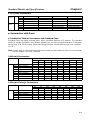
3,000-r/min Flat-style Servomotors
Specifications
Model
With incremental encoder
Without brake
200 V 100 W
200 W
400 W
750 W
With brake
With absolute encoder
Without brake
With brake
1/5
R88M-WP10030H-G05BJ R88M-WP10030H-BG05BJ R88M-WP10030T-G05BJ R88M-WP10030T-BG05BJ
1/11
R88M-WP10030H-G11BJ R88M-WP10030H-BG11BJ R88M-WP10030T-G11BJ R88M-WP10030T-BG11BJ
1/21
R88M-WP10030H-G21BJ R88M-WP10030H-BG21BJ R88M-WP10030T-G21BJ R88M-WP10030T-BG21BJ
1/33
R88M-WP10030H-G33BJ R88M-WP10030H-BG33BJ R88M-WP10030T-G33BJ R88M-WP10030T-BG33BJ
1/5
R88M-WP20030H-G05BJ R88M-WP20030H-BG05BJ R88M-WP20030T-G05BJ R88M-WP20030T-BG05BJ
1/11
R88M-WP20030H-G11BJ R88M-WP20030H-BG11BJ R88M-WP20030T-G11BJ R88M-WP20030T-BG11BJ
1/21
R88M-WP20030H-G21BJ R88M-WP20030H-BG21BJ R88M-WP20030T-G21BJ R88M-WP20030T-BG21BJ
1/33
R88M-WP20030H-G33BJ R88M-WP20030H-BG33BJ R88M-WP20030T-G33BJ R88M-WP20030T-BG33BJ
1/5
R88M-WP40030H-G05BJ R88M-WP40030H-BG05BJ R88M-WP40030T-G05BJ R88M-WP40030T-BG05BJ
1/11
R88M-WP40030H-G11BJ R88M-WP40030H-BG11BJ R88M-WP40030T-G11BJ R88M-WP40030T-BG11BJ
1/21
R88M-WP40030H-G21BJ R88M-WP40030H-BG21BJ R88M-WP40030T-G21BJ R88M-WP40030T-BG21BJ
1/33
R88M-WP40030H-G33BJ R88M-WP40030H-BG33BJ R88M-WP40030T-G33BJ R88M-WP40030T-BG33BJ
1/5
R88M-WP75030H-G05BJ R88M-WP75030H-BG05BJ R88M-WP75030T-G05BJ R88M-WP75030T-BG05BJ
1/11
R88M-WP75030H-G11BJ R88M-WP75030H-BG11BJ R88M-WP75030T-G11BJ R88M-WP75030T-BG11BJ
1/21
R88M-WP75030H-G21BJ R88M-WP75030H-BG21BJ R88M-WP75030T-G21BJ R88M-WP75030T-BG21BJ
1/33
1.5 kW 1/5
R88M-WP75030H-G33BJ R88M-WP75030H-BG33BJ R88M-WP75030T-G33BJ R88M-WP75030T-BG33BJ
R88M-WP1K530HG05BJ
R88M-WP1K530HBG05BJ
R88M-WP1K530T-G05BJ R88M-WP1K530TBG05BJ
1/11
R88M-WP1K530HG11BJ
R88M-WP1K530HBG11BJ
R88M-WP1K530T-G11BJ R88M-WP1K530TBG11BJ
1/21
R88M-WP1K530HG21BJ
R88M-WP1K530HBG21BJ
R88M-WP1K530T-G21BJ R88M-WP1K530TBG21BJ
1/33
R88M-WP1K530HG33BJ
R88M-WP1K530HBG33BJ
R88M-WP1K530T-G33BJ R88M-WP1K530TBG33BJ
2-13
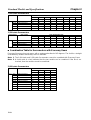
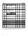
Chapter 2
Standard Models and Specifications
1,000-r/min Servomotors
Specifications
Model
With incremental encoder
200 V 300 W
600 W
900 W
With brake
R88M-W30010H-G05BJ
R88M-W30010H-BG05BJ
1/9
R88M-W30010H-G09BJ
R88M-W30010H-BG09BJ
R88M-W30010T-G09BJ
R88M-W30010T-BG09BJ
1/20
R88M-W30010H-G20BJ
R88M-W30010H-BG20BJ
R88M-W30010T-G20BJ
R88M-W30010T-BG20BJ
1/29
R88M-W30010H-G29BJ
R88M-W30010H-BG29BJ
R88M-W30010T-G29BJ
R88M-W30010T-BG29BJ
1/45
R88M-W30010H-G45BJ
R88M-W30010H-BG45BJ
R88M-W30010T-G45BJ
R88M-W30010T-BG45BJ
1/5
R88M-W60010H-G05BJ
R88M-W60010H-BG05BJ
R88M-W60010T-G05BJ
R88M-W60010T-BG05BJ
1/9
R88M-W60010H-G09BJ
R88M-W60010H-BG09BJ
R88M-W60010T-G09BJ
R88M-W60010T-BG09BJ
1/20
R88M-W60010H-G20BJ
R88M-W60010H-BG20BJ
R88M-W60010T-G20BJ
R88M-W60010T-BG20BJ
1/29
R88M-W60010H-G29BJ
R88M-W60010H-BG29BJ
R88M-W60010T-G29BJ
R88M-W60010T-BG29BJ
1/45
R88M-W60010H-G45BJ
R88M-W60010H-BG45BJ
R88M-W60010T-G45BJ
R88M-W60010T-BG45BJ
1/5
R88M-W90010H-G05BJ
R88M-W90010H-BG05BJ
R88M-W90010T-G05BJ
R88M-W90010T-BG05BJ
1/9
R88M-W90010H-G09BJ
R88M-W90010H-BG09BJ
R88M-W90010T-G09BJ
R88M-W90010T-BG09BJ
1/20
R88M-W90010H-G20BJ
R88M-W90010H-BG20BJ
R88M-W90010T-G20BJ
R88M-W90010T-BG20BJ
1/29
R88M-W90010H-G29BJ
R88M-W90010H-BG29BJ
R88M-W90010T-G29BJ
R88M-W90010T-BG29BJ
1/45
R88M-W90010H-G45BJ
R88M-W90010H-BG45BJ
R88M-W90010T-G45BJ
R88M-W90010T-BG45BJ
R88M-W1K210H-G05BJ
R88M-W1K210H-BG05BJ R88M-W1K210T-G05BJ
R88M-W1K210T-BG05BJ
1/5
1.2 kW 1/5
2 kW
With absolute encoder
Without brake
Without brake
R88M-W30010T-G05BJ
With brake
R88M-W30010T-BG05BJ
1/9
R88M-W1K210H-G09BJ
R88M-W1K210H-BG09BJ R88M-W1K210T-G09BJ
R88M-W1K210T-BG09BJ
1/20
R88M-W1K210H-G20BJ
R88M-W1K210H-BG20BJ R88M-W1K210T-G20BJ
R88M-W1K210T-BG20BJ
1/29
R88M-W1K210H-G29BJ
R88M-W1K210H-BG29BJ R88M-W1K210T-G29BJ
R88M-W1K210T-BG29BJ
R88M-W1K210T-BG45BJ
1/45
R88M-W1K210H-G45BJ
R88M-W1K210H-BG45BJ R88M-W1K210T-G45BJ
1/5
R88M-W2K010H-G05BJ
R88M-W2K010H-BG05BJ R88M-W2K010T-G05BJ
R88M-W2K010T-BG05BJ
1/9
R88M-W2K010H-G09BJ
R88M-W2K010H-BG09BJ R88M-W2K010T-G09BJ
R88M-W2K010T-BG09BJ
1/20
R88M-W2K010H-G20BJ
R88M-W2K010H-BG20BJ R88M-W2K010T-G20BJ
R88M-W2K010T-BG20BJ
1,500-r/min Servomotors
Specifications
Model
With incremental encoder
Without brake
200 V 450 W
---
With absolute encoder
Without brake
With brake
---
R88M-W45015T-G05BJ
R88M-W45015T-BG05BJ
1/9
---
---
R88M-W45015T-G09BJ
R88M-W45015T-BG09BJ
1/20
---
---
R88M-W45015T-G20BJ
R88M-W45015T-BG20BJ
1/29
---
---
R88M-W45015T-G29BJ
R88M-W45015T-BG29BJ
1/45
---
---
R88M-W45015T-G45BJ
R88M-W45015T-BG45BJ
1/5
---
---
R88M-W85015T-G05BJ
R88M-W85015T-BG05BJ
1/9
---
---
R88M-W85015T-G09BJ
R88M-W85015T-BG09BJ
1/20
---
---
R88M-W85015T-G20BJ
R88M-W85015T-BG20BJ
1/29
---
---
R88M-W85015T-G29BJ
R88M-W85015T-BG29BJ
1/45
---
---
R88M-W85015T-G45BJ
R88M-W85015T-BG45BJ
1.3 kW 1/5
---
---
R88M-W1K315T-G05BJ
R88M-W1K315T-BG05BJ
1/9
---
---
R88M-W1K315T-G09BJ
R88M-W1K315T-BG09BJ
1/20
---
---
R88M-W1K315T-G20BJ
R88M-W1K315T-BG20BJ
1/29
---
---
R88M-W1K315T-G29BJ
R88M-W1K315T-BG29BJ
1/45
---
---
R88M-W1K315T-G45BJ
R88M-W1K315T-BG45BJ
1.8 kW 1/5
---
---
R88M-W1K815T-G05BJ
R88M-W1K815T-BG05BJ
1/9
---
---
R88M-W1K815T-G09BJ
R88M-W1K815T-BG09BJ
1/20
---
---
R88M-W1K815T-G20BJ
R88M-W1K815T-BG20BJ
1/29
---
---
R88M-W1K815T-G29BJ
R88M-W1K815T-BG29BJ
850 W
2-14
1/5
With brake
Chapter 2
Standard Models and Specifications
●
Servomotors with Economy Gears (Straight Shaft with Key)
3,000-r/min Servomotors
Specifications
Model
With incremental encoder
200 V 100 W
200 W
400 W
750 W
With absolute encoder
Without brake
With brake
Without brake
1/5
R88M-W10030H-G05CJ
R88M-W10030H-BG05CJ
R88M-W10030T-G05CJ
R88M-W10030T-BG05CJ
With brake
1/9
R88M-W10030H-G09CJ
R88M-W10030H-BG09CJ
R88M-W10030T-G09CJ
R88M-W10030T-BG09CJ
1/15
R88M-W10030H-G15CJ
R88M-W10030H-BG15CJ
R88M-W10030T-G15CJ
R88M-W10030T-BG15CJ
1/25
R88M-W10030H-G25CJ
R88M-W10030H-BG25CJ
R88M-W10030T-G25CJ
R88M-W10030T-BG25CJ
1/5
R88M-W20030H-G05CJ
R88M-W20030H-BG05CJ
R88M-W20030T-G05CJ
R88M-W20030T-BG05CJ
1/9
R88M-W20030H-G09CJ
R88M-W20030H-BG09CJ
R88M-W20030T-G09CJ
R88M-W20030T-BG09CJ
1/15
R88M-W20030H-G15CJ
R88M-W20030H-BG15CJ
R88M-W20030T-G15CJ
R88M-W20030T-BG15CJ
1/25
R88M-W20030H-G25CJ
R88M-W20030H-BG25CJ
R88M-W20030T-G25CJ
R88M-W20030T-BG25CJ
1/5
R88M-W40030H-G05CJ
R88M-W40030H-BG05CJ
R88M-W40030T-G05CJ
R88M-W40030T-BG05CJ
1/9
R88M-W40030H-G09CJ
R88M-W40030H-BG09CJ
R88M-W40030T-G09CJ
R88M-W40030T-BG09CJ
1/15
R88M-W40030H-G15CJ
R88M-W40030H-BG15CJ
R88M-W40030T-G15CJ
R88M-W40030T-BG15CJ
1/25
R88M-W40030H-G25CJ
R88M-W40030H-BG25CJ
R88M-W40030T-G25CJ
R88M-W40030T-BG25CJ
1/5
R88M-W75030H-G05CJ
R88M-W75030H-BG05CJ
R88M-W75030T-G05CJ
R88M-W75030T-BG05CJ
1/9
R88M-W75030H-G09CJ
R88M-W75030H-BG09CJ
R88M-W75030T-G09CJ
R88M-W75030T-BG09CJ
1/15
R88M-W75030H-G15CJ
R88M-W75030H-BG15CJ
R88M-W75030T-G15CJ
R88M-W75030T-BG15CJ
1/25
R88M-W75030H-G25CJ
R88M-W75030H-BG25CJ
R88M-W75030T-G25CJ
R88M-W75030T-BG25CJ
3,000-r/min Flat-style Servomotors
Specifications
Model
With incremental encoder
Without brake
200 V 100 W
200 W
400 W
750 W
With brake
With absolute encoder
Without brake
With brake
1/5
R88M-WP10030H-G05CJ R88M-WP10030H-BG05CJ R88M-WP10030T-G05CJ R88M-WP10030T-BG05CJ
1/9
R88M-WP10030H-G09CJ R88M-WP10030H-BG09CJ R88M-WP10030T-G09CJ R88M-WP10030T-BG09CJ
1/15
R88M-WP10030H-G15CJ R88M-WP10030H-BG15CJ R88M-WP10030T-G15CJ R88M-WP10030T-BG15CJ
1/25
R88M-WP10030H-G25CJ R88M-WP10030H-BG25CJ R88M-WP10030T-G25CJ R88M-WP10030T-BG25CJ
1/5
R88M-WP20030H-G05CJ R88M-WP20030H-BG05CJ R88M-WP20030T-G05CJ R88M-WP20030T-BG05CJ
1/9
R88M-WP20030H-G09CJ R88M-WP20030H-BG09CJ R88M-WP20030T-G09CJ R88M-WP20030T-BG09CJ
1/15
R88M-WP20030H-G15CJ R88M-WP20030H-BG15CJ R88M-WP20030T-G15CJ R88M-WP20030T-BG15CJ
1/25
R88M-WP20030H-G25CJ R88M-WP20030H-BG25CJ R88M-WP20030T-G25CJ R88M-WP20030T-BG25CJ
1/5
R88M-WP40030H-G05CJ R88M-WP40030H-BG05CJ R88M-WP40030T-G05CJ R88M-WP40030T-BG05CJ
1/9
R88M-WP40030H-G09CJ R88M-WP40030H-BG09CJ R88M-WP40030T-G09CJ R88M-WP40030T-BG09CJ
1/15
R88M-WP40030H-G15CJ R88M-WP40030H-BG15CJ R88M-WP40030T-G15CJ R88M-WP40030T-BG15CJ
1/25
R88M-WP40030H-G25CJ R88M-WP40030H-BG25CJ R88M-WP40030T-G25CJ R88M-WP40030T-BG25CJ
1/5
R88M-WP75030H-G05CJ R88M-WP75030H-BG05CJ R88M-WP75030T-G05CJ R88M-WP75030T-BG05CJ
1/9
R88M-WP75030H-G09CJ R88M-WP75030H-BG09CJ R88M-WP75030T-G09CJ R88M-WP75030T-BG09CJ
1/15
R88M-WP75030H-G15CJ R88M-WP75030H-BG15CJ R88M-WP75030T-G15CJ R88M-WP75030T-BG15CJ
1/25
R88M-WP75030H-G25CJ R88M-WP75030H-BG25CJ R88M-WP75030T-G25CJ R88M-WP75030T-BG25CJ
2-15
Chapter 2
Standard Models and Specifications
2-2
Servo Driver and Servomotor Combinations
The tables in this section show the possible combinations of OMNUC W-series Servo
Drivers (with built-in MECHATROLINK-II communications) and Servomotors. No other
combinations are possible.
Note The boxes (-@) at the ends of the model numbers are for options such as shaft type, brake,
waterproofing, decelerator, and so on.
■
3,000-r/min Servomotors and Servo Drivers
Voltage
200 V
■
Servomotor
With incremental
With absolute
encoder
encoder
R88M-W05030H-@
R88M-W05030T-@
R88M-W10030H-@
R88M-W10030T-@
R88M-W20030H-@
R88M-W20030T-@
R88M-W40030H-@
R88M-W40030T-@
R88M-W75030H-@
R88M-W75030T-@
R88M-W1K030H-@
R88M-W1K030T-@
R88M-W1K530H-@
R88M-W1K530T-@
R88M-W2K030H-@
R88M-W2K030T-@
R88M-W3K030H-@
R88M-W3K030T-@
Servo Driver
R88D-WNA5H-ML2/A5L-M2
R88D-WN01H-ML2/01L-ML2
R88D-WN02H-ML2/02L-ML2
R88D-WN04H-ML2/04L-ML2
R88D-WN08H-ML2
R88D-WN10H-ML2
R88D-WN15H-ML2
R88D-WN20H-ML2
R88D-WN30H-ML2
3,000-r/min Flat-style Servomotors and Servo Drivers
Voltage
200 V
■
Rated
output
50 W
100 W
200 W
400 W
750 W
1 kW
1.5 kW
2 kW
3 kW
Servomotor
Rated
With incremental
With absolute
output
encoder
encoder
100 W R88M-WP10030H-@
R88M-WP10030T-@
200 W R88M-WP20030H-@
R88M-WP20030T-@
400 W R88M-WP40030H-@
R88M-WP40030T-@
750 W R88M-WP75030H-@
R88M-WP75030T-@
1.5 kW R88M-WP1K530H-@ R88M-WP1K530T-@
Servo Driver
R88D-WN01H-ML2/01L-ML2
R88D-WN02H-ML2/02L-ML2
R88D-WN04H-ML2/04L-ML2
R88D-WN08H-ML2
R88D-WN15H-ML2
1,000-r/min Servomotors and Servo Drivers
Voltage
200 V
2-16
Servomotor
Rated
With incremental
With absolute
output
encoder
encoder
300 W R88M-W30010H-@
R88M-W30010T-@
600 W R88M-W60010H-@
R88M-W60010T-@
900 W R88M-W90010H-@
R88M-W90010T-@
1.2 kW R88M-W1K210H-@
R88M-W1K210T-@
2 kW
R88M-W2K010H-@
R88M-W2K010T-@
Servo Driver
R88D-WN05H-ML2
R88D-WN10H-ML2
R88D-WN10H-ML2
R88D-WN15H-ML2
R88D-WN20H-ML2
Chapter 2
Standard Models and Specifications
■
1,500-r/min Servomotors and Servo Drivers
Voltage
200 V
Rated
output
450 W
850 W
1.3 kW
1.8 kW
Servomotor
With incremental
With absolute
encoder
encoder
--R88M-W45015T-@
--R88M-W85015T-@
--R88M-W1K315T-@
--R88M-W1K815T-@
Servo Driver
R88D-WN05H-ML2
R88D-WN10H-ML2
R88D-WN15H-ML2
R88D-WN20H-ML2
2-17
Chapter 2
Standard Models and Specifications
2-3
External and Mounted Dimensions
2-3-1 AC Servo Drivers
■
●
Single-phase 100 V: R88D-WNA5L-ML2/-WN01L-ML2/-WN02L-ML2
(50 to 200 W)
Single-phase 200 V: R88D-WNA5H-ML2/-WN01H-ML2/-WN02H-ML2
(50 to 200 W)
Wall Mounting
External dimensions
Mounted dimensions
Mounting Holes
(6)
Two M-4 holes
5.5
5
12 (16)
(4.5)
SW1
CN6
CN3
L1
L2
C
N
3
L2C
139.5 ±0.5
Terminal
Block
150
L1C
B1/ +
CN1
B2
C
N
1
U
(Mounting pitch)
C
N
6
A/B
CHARGE
V
W
C
N
2
Ground terminals
Two M4 screws
CN2
CN4
5
C
N
4
45
Nameplate
(18)
(75)
2-18
130
5
32±0.5
(Mounting
pitch)
45
8
Chapter 2
Standard Models and Specifications
Front Panel Mounting (Using Mounting Brackets)
External dimensions
105.5
170 ±0.5 (Mounting pitch)
CN6
SW1
C
N
6
A/B
CHARGE
L1
CN3
L2
185
150
170
L1C
C
N
3
L2C
B1/ +
CN1
B2
Terminal
Block
C
N
1
U
V
W
Mounting Holes
Two M-4 holes
7
(4.5)
10
22.5 2
7.5
5 dia.
(6)
(16)
(7.5)
(25.5)
36
19.5
5
12
17.5
7.5
1.5
Mounted dimensions
150
156 min.
●
CN2
C
N
2
CN4
C
N
4
●
130
(7)
(75)
(10)
Nameplate
(18)
(7.5)
5
45
(17.5)
(7.5)
■
Ground
terminals
Two M4
screws
19.5 (25.5)
Single-phase 100 V: R88D-WN04L-ML2 (400 W)
Wall Mounting
External dimensions
Mounted dimensions
Mounting Holes
(6)
Air flow
C
N
6
A/B
SW1
CHARGE
CN3
C
N
3
L1C
L2C
B1/
Air flow
150
L2
CN1
B2
139.5 ±0.5
L1
C
N
1
(Mounting pitch)
CN6
Terminal
Block
150
Three M-4 holes
5.5
125
(16)
(4)
CN2
U
C
N
2
V
W
Nameplate Cooling fan
Air flow
(75)
6
58 ±0.5
(6)
(Mounting pitch)
18
70
(5)
Ground terminals
Two M4 screws
CN4
C
N
4
180
70
2-19
Chapter 2
Standard Models and Specifications
Front Panel Mounting (Using Mounting Brackets)
170 ±0.5 (Mounting
CN3
170
185
150
Air flow
CN1
CN2
CN4
Ground terminals
Two M4 screws
■
●
10
Cooling fan
18
Air flow
(75)
(7.5)
(7)
(10)
(7.5)
(17.5)
Nameplate
150
CN6
5
Mounting Holes
Two M-4 holes
pitch)
Air flow
Terminal
Block
(4)
(7.5)
7
5 dia.
24.5
2
(16)
(6)
(15.5)
18.5
36
36.5
(33.5)
125
7.5
Mounted dimensions
5
12
17.5
External dimensions
156 min.
●
180
36.5
70
(33.5)
70
Single-phase 200 VAC: R88D-WN04H-ML2 (400 W)
Wall Mounting
External dimensions
Mounted dimensions
Mounting Holes
(6)
5
12 (16)
CN6
SW1
CHARGE
5.5
Two M-4 holes
(4)
C
N
6
A/B
CN3
L2
Terminal
Block
L2C
C
N
3
139.5 ±0.5
150
L1C
B1/ +
CN1
B2
C
N
1
U
V
W
(Mounting pitch)
L1
CN2
C
N
2
CN4
Ground terminals
Two M4 screws
65
(18)
(75)
2-20
Nameplate
(5)
C
N
4
10
47 ±0.5
(Mounting pitch)
130
(8)
Chapter 2
Standard Models and Specifications
Front Panel Mounting (Using Mounting Brackets)
External dimensions
Mounted dimensions
Mounting Holes
(7.5)
(25.5)
22.5 2
105.5
7.5
7
10
(4)
185
150
170
170 ±0.5 (Mounting
CN3
CN1
150
CN6
Terminal
Block
Two M-4 holes
pitch)
125
5 dia.
(6)
(16)
36
17.5
7.5
21.5
39.5
156 min.
●
CN2
Nameplate
5
20
(18)
(75)
45
( 7.5 )
(7)
( 10 )
(7.5)
(17.5)
CN4
Ground
terminals
Two M4
screws
130
39.5
(25.5)
65
■
●
Single-phase 200 VAC: R88D-WN08HML2 (750 W)
Three-phase 200 VAC: R88D-WN05H-ML2/-WN10H-ML2 (500 W to 1 kW)
Wall Mounting
External dimensions
Mounted dimensions
Mounting Holes
(6)
Terminal
Block
CN3
C
N
3
L1C
CN1
L2C
B1/ +
B2
B3
C
N
1
1
CN2
2
U
C
N
2
V
W
CN4
C
N
4
Nameplate Cooling fan
Air flow
70
6
58 ±0.5
(6)
(Mounting pitch)
18
(75)
(5)
150
L2
Air flow
150
L2
139.5 ±0.5
L1
(Mounting pitch)
CN6
C
N
6
A/B
SW1
CHARGE
Ground terminals
Two M4 screws
Three M-4 holes
5.5
(4)
125
(16)
Air flow
180
70
2-21
Chapter 2
Standard Models and Specifications
Front Panel Mounting (Using Mounting Brackets)
External dimensions
Air flow
Terminal
Block
7
(4)
10
Mounting Holes
(16)
(33.5)
5 dia.
36.5
24.5
2
(7.5)
(6)
(15.5)
36
Two M-4 holes
5
12
17.5
7.5
18.5
Mounted dimensions
156 min.
150
170 ±0.5
185
150
170
CN1
(7)
CN3
Air flow
(10)
CN6
(Mounting pitch)
●
CN2
CN4
5
Ground terminals
Two M4 screws
■
●
Cooling fan
18
Air flow
(75)
(7.5)
(7.5)
(17.5)
Nameplate
180
(33.5)
36.5
70
70
Three-phase 200 V: R88D-WN15H-ML2 (1.5 kW)
Wall Mounting
External dimensions
Mounted dimensions
Mounting Holes
(6)
SW1
L2
C
N
6
A/B
L1
L3
CN3
L1C
C
N
3
B1/ +
150
150
L2C
B2
B3
CN1
-1
-2
139.5 ±0.5
L1
C
N
1
U
V
W
C
N
2
(Mounting pitch)
CN6
CHARGE
Terminal
Block
Three M-4 holes
5.5
5˚
12
(16)
(4)
CN2
CN4
Ground terminals
Two M4 screws
(5)
C
N
4
Nameplate
5
90
2-22
(75)
80 ±0.5
(Mounting pitch)
18
180
90
(5)
Chapter 2
Standard Models and Specifications
●
Front Panel Mounting (Using Mounting Brackets)
Mounted Dimensions
External Dimensions
Mounting Holes
(6)
Four M-4 holes
7
(16)
˚
125
Two, 5 dia.
7.5
7.5
15.5
Air flow
CN6
A/B
L2
CN3
L3
185
170
154
L2C
C
N
3
B1/ +
B2
Terminal
blocks
Ground terminals
Two M4 screws
170 ±0.5
L1C
CN1
B3
-1
-2
C
N
1
U
156 min.
154
C
N
6
SW1
L1
(Mounting pitch)
CHARGE
CN2
V
W
C
N
2
CN4
■
●
50
90
18
(20)
(7.5)
(7.5)
(15.5)
20
(2.2)
Air flow
Nameplate
2
5
24.5
(75)
(7)
C
N
4
20
(5)
180
50 ±0.5
Three-phase 200 V: R88D-WN20H-ML2/-WN30H-ML2 (2 to 3 kW)
Wall Mounting
External dimensions
Mounted dimensions
Mounting Holes
(6)
Four M-4 holes
5
˚
125
(16)
(4)
CN6
180
170 ±0.5
(Mounting pitch)
180
(5)
CN3
CN1
5
CN2
CN4
Nameplate
Terminal Block
M4 screws
Ground terminals Two
M4 screws
90 ±0.5
(5)
(Mounting pitch)
100
(75)
180
(20)
(Mounting pitch)
100
2-23
Chapter 2
Standard Models and Specifications
Front Panel Mounting (Using Mounting Brackets)
Mounted dimensions
External dimensions
100
Mounting Holes
(6)
24.5
125˚
CHARGE
CN6
C
N
6
CN3
215
180
200
C
N
3
CN1
C
N
1
CN2
C
N
2
186 min.
A/B
180
SW1
200 ±0.5
Terminal
Block
Four M-4 holes
(16)
2
(10)
17.5
7.5
Air flow
7
Two, 5 dia.
10
50
(7.5)
25
(Mounting pitch)
2.2
(7)
●
CN4
C
N
4
Nameplate
Ground terminals
Two M4 screws
2-24
(7.5)
(17.5)
(7.5)
5
Air flow
2.2
25
50
102.2
(75)
180
(5)
27.2
50 ±0.5
(25)
(Mounting pitch)
102.2
Chapter 2
Standard Models and Specifications
2-3-2 AC Servomotors
■
3,000-r/min Servomotors without a Brake
●
200 V AC: 50 W/100 W
R88M-W05030H(-S1)/-W10030H(-S1) [Incremental]
R88M-W05030T(-S1)/-W10030T(-S1) [Absolute]
Dimensions (mm)
Model
300 ±30
LL
S
b
h
t1
M
l
R88M-W05030@-@
77
6h6
2
2
1.2
M2.5
5
R88M-W10030@-@
94.5
8h6
3
3
1.8
M3
6
Dimensions of shaft end with key (-S1)
7 dia.
19.5
20
h
b
6 dia.
21.5
9.5
300 ±30
5
Two, 4.3 dia.
t1
ia.
40
30h7 dia.
11
S dia.
14
46 d
Dimensions of shaft end with key and tap (-S2)
2.5
LL
40
25
14
200 V AC: 50 W/100 W
R88M-W05030H-B(S1)/-W10030H-B(S1) [Incremental]
R88M-W05030T-B(S1)/-W10030T-B(S1) [Absolute]
Dimensions (mm)
Model
300 ±30
LL
S
b
h
t1
M
l
R88M-W05030@-B@
108.5
6h6
2
2
1.2
M2.5
5
R88M-W10030@-B@
135
8h6
3
3
1.8
M3
6
Dimensions of shaft end with key (-BS1)
h
7 dia.
b
6 dia.
300 ±30
19.5
21.5
27
5
Two, 4.3 dia.
t1
46 d
ia.
40
S dia.
30h7 dia.
14
11
Dimensions of shaft end with key and
tap (-BS2)
M (effective
h
5
LL
2.5
depth: l)
b
●
t1
3,000-r/min Servomotors with a Brake
9.5
■
M (effective depth: l)
b
h
5
40
25
14
t1
2-25
Chapter 2
Standard Models and Specifications
■
●
3,000-r/min Servomotors without a Brake
200 V AC: 200 W/400 W/750 W
R88M-W20030H(-S1)/-W40030H(-S1)/-W75030H(-S1) [Incremental]
R88M-W20030T(-S1)/-W40030T(-S1)/-W75030T(-S1) [Absolute]
Dimensions (mm)
Model
300 ±30
LL
LR
C
D1
D2
G
Z
S
QK
R88M-W20030@-@
96.5
30
60
70
50h7
6
5.5
14h6
20
R88M-W40030@-@
124.5
30
60
70
50h7
6
5.5
14h6
20
R88M-W75030@-@
145
40
80
90
70h7
8
7
16h6
30
Dimensions of output section of
750-W Servomotors
6 dia.
7 dia.
13
21.5
300 ±30
9
20
2
Dimensions of shaft end with key (-S1)
S dia.
D1 d
5
ia.
C
D2 dia.
5
11
Four, Z dia.
3
QK
G
3
LR
C
Dimensions of shaft end with key
and tap (-S2)
5
5
LL
QK
2-26
3
M5
(effective depth: 8)
Chapter 2
Standard Models and Specifications
200 V AC: 200 W/400 W/750 W
R88M-W20030H-B(S1)/-W40030H-B(S1)/-W75030H-B(S1) [Incremental]
R88M-W20030T-B(S1)/-W40030T-B(S1)/-W75030T-B(S1) [Absolute]
Dimensions (mm)
Model
300 ±30
LL
LR
C
D1
D2
G
Z
S
QK
R88M-W20030@-B@
136
30
60
70
50h7
6
5.5
14h6
20
R88M-W40030@-B@
164
30
60
70
50h7
6
5.5
14h6
20
R88M-W75030@-B@
189.5
40
80
90
70h7
8
7
16h6
30
Dimensions of output section of
750-W Servomotors
6 dia.
7 dia.
27
300 ±30
21.5
Four, Z dia.
Dimensions of shaft end with key
(-BS1)
D1 d
ia.
D2 dia.
5
5
S dia.
2
C
3
QK
G
LL
3
LR
C
Dimensions of shaft end with key
and tap (-BS2)
5
5
13
11
●
3,000-r/min Servomotors with a Brake
9
■
QK
M5
(effective depth: 8)
3
2-27
Chapter 2
Standard Models and Specifications
■
●
3,000-r/min Servomotors without a Brake
200 V AC: 1 kW/1.5 kW/2 kW/3 kW
R88M-W1K030H(-S2)/-W1K5030H(-S2)/-W2K030H(-S2)/-W3K030H(-S2) [Incremental]
R88M-W1K030T(-S2)/-W1K5030T(-S2)/-W2K030T(-S2)/-W3K030T(-S2) [Absolute]
LL
LR
F
C
D1
dia.
C
D2 dia.
S dia.
G
.
dia
KL2
KL1
D3
Four, Z dia.
2
KB1
KB2
Dimensions of shaft end with key (-S2)
LL
R88M-W1K030@-@
LR KB1 KB2 KL1 KL2
D1
D2
D3
F
G
Z
S
QK
88 100 115
95h7
130
3
10
7
24h6
32
63 124 178 114 88 130 145
110h7
165
6
12
9
28h6
50
149
76 128
R88M-W1K530@-@
175
45 102 154 96
R88M-W2K030@-@
198
125 177
R88M-W3K030@-@
199
C
Note: The external dimensions are the same for IP67 (waterproof) models (-O@).
2-28
8
M8
(effective depth: 16)
Dimensions (mm)
Model
QK
4
7
Chapter 2
Standard Models and Specifications
■
●
3,000-r/min Servomotors with a Brake
200 V AC: 1 kW/1.5 kW/2 kW/3 kW
R88M-W1K030H-B(S2)/-W1K5030H-B(S2)/-W2K030H-B(S2)/-W3K030H-B(S2)
[Incremental]
R88M-W1K030T-B(S2)/-W1K5030T-B(S2)/-W2K030T-B(S2)/-W3K030T-B(S2)
[Absolute]
LL
LR
F
C
S dia.
G
dia.
C
D2 dia.
D1
.
dia
KL2
KL1
D3
Four, Z dia.
2
KB1
KB2
Dimensions of shaft end with key (-BS2)
M8
(effective depth: 16)
Dimensions (mm)
LL
R88M-W1K030@-B@
193
R88M-W1K530@-B@
219
R88M-W2K030@-B@
242
R88M-W3K030@-B@
237
LR KB1 KB2 KL1 KL2
C
D1
D2
D3
F
G
Z
S
QK
93 197 102 88 100 115
95h7
130
3
10
7
24h6
32
110h7
165
6
12
9
28h6
50
8
Model
67 171
45
116 220
63 114 216 119 88 130 145
Note: The external dimensions are the same for IP67 (waterproof) models (-BO@).
QK
4
7
2-29
Chapter 2
Standard Models and Specifications
3,000-r/min Flat-style Servomotors without a Brake
■
200 V AC: 100 W/200 W/400 W/750 W/1.5 kW
R88M-WP10030H(-S1)/-WP20030H(-S1)/-WP40030H(-S1)/-WP75030H(-S1)/
-WP1K530H(-S1) [Incremental]
R88M-WP10030T(-S1)/-WP20030T(-S1)/-WP40030T(-S1)/-WP75030T(-S1)/
-WP1K530T(-S1) [Absolute]
Model
Dimensions (mm)
With key (shaft
end dimensions)
Basic servomotor dimensions
LL
LR C
62
25 60
67
30 80
87
86.5
40 120
114.5
13
D1
70
D2
50h7
F
3
G
6
Z
5.5
S
8h6
QK
14
b
3
h
3
90
70h7
3
8
7
14h6
16
5
5
145
110h7
10
16h6
19h6
22
5
6
5
6
3.5
10
Cable lead-in section
t1 W1 W2 DW1 DW2 A1
1.8 1
4
39
22
3
3.5
7
49
35
3
1.5
3.5
7
77
55
A2
A3
18
9
A4
A5
21
14
25
28
38
19
Tap
M
M3
l
6
M5
8
M6
10
300 ±30
Dimensions of shaft end with
key (-@S1)
Dimensions of shaft end with key
and tap (-@S2)
h
b
h
7 dia.
6 dia.
R88M-WP10030@-@
R88M-WP20030@-@
R88M-WP40030@-@
R88M-WP75030@-@
R88M-WP1K530@-@
Waterproof type
(flange dimensions)
A3
b
●
M
(effective depth: l)
A4
QK
t1
QK
t1
A2
300 ±30
G
LL
F
LR
C
Four, Z dia.
W1
W2
2-30
DW1 dia.
DW2 dia.
dia.
C
S dia.
A5
D2 dia.
A1
IP67 (-W@) flange dimensions
D1
Chapter 2
Standard Models and Specifications
3,000-r/min Flat-style Servomotors with a Brake
■
200 V AC: 100 W/200 W/400 W/750 W/1.5 kW
R88M-WP10030H-B(S1)/-WP20030H-B(S1)/-WP40030H-B(S1)/-WP75030H-B(S1)/
-WP1K530H-B(S1) [Incremental]
R88M-WP10030T-B(S1)/-WP20030T-B(S1)/-WP40030T-B(S1)/-WP75030T-B(S1)/
-WP1K530T-B(S1) [Absolute]
Model
Dimensions (mm)
With key (shaft
end dimensions)
Basic servomotor dimensions
LL
LR C
91
25 60
98.5
30 80
118.5
120
40 120
148
6 dia.
R88M-WP10030@-B@
R88M-WP20030@-B@
R88M-WP40030@-B@
R88M-WP75030@-B@
R88M-WP1K530@-B@
D1
70
D2
50h7
F
3
G
6
Z
5.5
S
8h6
QK
14
b
3
h
3
90
70h7
3
8
7
14h6
16
5
5
10
10
16h6
19h6
22
5
6
5
6
145 110h7 3.5
Waterproof type
(flange dimensions)
Cable lead-in section
t1 W1 W2 DW1 DW2 A1
1.8 1
4
39
22
3
3.5
7
49
35
3
1.5
3.5
7
77
55
A2
A3
18
9
A4
A5
21
23
38
26
25
28
Tap
M
M3
l
6
M5
8
M6
10
300 ±30
Dimensions of shaft end with
key (-B@S1)
Dimensions of shaft end with key
and tap (-B@S2)
b
h
b
7 dia.
h
A3
M
(effective depth: l)
A4
13
QK
t1
A2
300 ±30
QK
t1
G
LL
F
LR
DW2 dia.
C
S dia.
A5
dia.
D2 dia.
A1
IP67 (-BW@) flange dimensions
D1
C
DW1 dia.
●
Four, Z dia.
W1
W2
2-31
Chapter 2
Standard Models and Specifications
●
1,000-r/min Servomotors without a Brake
200 V AC: 300 W/600 W/900 W/1.2 kW/2.0 kW
R88M-W30010H(-S2)/-W60010H(-S2)/-W90010H(-S2)/-W1K210H(-S2)/-W2K010H(-S2)
[Incremental]
R88M-W30010T(-S2)/-W60010T(-S2)/-W90010T(-S2)/-W1K210T(-S2)/-W2K010T(-S2)
[Absolute]
LL
Dimensions of output section of
300-W to 900-W Servomotors
LR
F
C
D1
dia.
.
Dimensions of shaft end with
key (-S2)
dia
KL2
D3
KL1
12
C
D2 dia.
S dia.
G
30 dia.
■
M (Effective depth: l)
b
Four, Z dia.
KB1
QK
t1
KB2
h
Dimensions (mm)
Model (mm)
LL
R88M-W30010@-@
138
R88M-W60010@-@
161
R88M-W90010@-@
185
R88M-W1K210@-@
166
R88M-W2K010@-@
192
LR
58
KB1
KB2
65
117
88
140
112
164
89
144
115
170
KL1
KL2
C
D1
D2
D3
F
G
Z
109
88
130
145
110h7
165
6
12
9
19h6
88
180
200
0
114.3 −0.025
230
Note: The external dimensions are the same for IP67 (waterproof) models (-O@).
2-32
QK
3.2
18
13.5
b
h
t1
5
5
3
6
6
3.5
10
8
5
25
22h6
140
79
S
35 +0.01
0
60
M
l
M5
12
M12
25
Chapter 2
Standard Models and Specifications
200 V AC: 300 W/600 W/900 W/1.2 kW/2.0 kW
R88M-W30010H-B(S2)/-W60010H-B(S2)/-W90010H-B(S2)/-W1K210H-B(S2)/
-W2K010H-B(S2) [Incremental]
R88M-W30010T-B(S2)/-W60010T-B(S2)/-W90010T-B(S2)/-W1K210T-B(S2)/
-W2K010T-B(S2) [Absolute]
LL
Dimensions of output section of
300-W to 900-W Servomotors
LR
F
C
D1
dia.
Dimensions of shaft end with
key (-BS2)
.
dia
KL2
D3
KL1
12
C
D2 dia.
S dia.
G
30 dia.
●
1,000-r/min Servomotors with a Brake
M (Effective depth: l)
Four, Z dia.
b
■
QK
t1
KB1
h
KB2
Dimensions (mm)
Model (mm)
LL
R88M-W30010@-B@
176
R88M-W60010@-B@
199
R88M-W90010@-B@
223
R88M-W1K210@-B@
217
R88M-W2K010@-B@
243
LR
58
KB1
KB2
56
154
79
177
103
201
79
195
105
221
KL1
KL2
C
D1
D2
D3
F
G
Z
120
88
130
145
110h7
165
6
12
9
QK
19h6
88
180
200
0
114.3 −0.025
230
3.2
18
13.5
b
h
t1
5
5
3
6
6
3.5
10
8
5
25
22h6
146
79
S
35 +0.01
0
60
M
l
M5
12
M12
25
Note: The external dimensions are the same for IP67 (waterproof) models (-BO@).
2-33
Chapter 2
Standard Models and Specifications
●
1,500-r/min Servomotors without a Brake
200 V AC: 450 W/850 W/1.3 kW/1.8 kW
R88M-W45015T(-S2)/-W85015T(-S2)/-W1K315T(-S2)/-W1K815T(-S2) [Absolute]
LL
Dimensions of output section of
450-W to 1.3-kW Servomotors
LR
F
C
D1
dia.
Dimensions of shaft end with
key (-S2)
.
dia
KL2
D3
KL1
12
C
D2 dia.
S dia.
G
30 dia.
■
M (Effective depth: l)
b
Four, Z dia.
QK
KB1
t1
h
KB2
Dimensions (mm)
Model (mm)
LL
R88M-W45015T-@
138
R88M-W85015T-@
161
R88M-W1K315T-@
185
R88M-W1K815T-@
166
LR
58
79
KB1
KB2
65
117
88
140
112
164
89
144
KL1
KL2
C
D1
D2
D3
F
G
Z
109
88
130
145
110h7
165
6
12
9
QK
19h6
140
88
180
200
0
114.3 −0.025
230
3.2
18
13.5
b
h
t1
5
5
3
6
6
3.5
10
8
5
25
22h6
Note: The external dimensions are the same for IP67 (waterproof) models (O@).
2-34
S
35 +0.01
0
60
M
l
M5
12
M12
25
Chapter 2
Standard Models and Specifications
200 V AC: 450 W/850 W/1.3 kW/1.8 kW
R88M-W45015T-B(S2)/-W85015T-B(S2)/-W1K315T-B(S2)/-W1K815T-B(S2) [Absolute]
LL
Dimensions of output section of
450-W to 1.3-kW Servomotors
LR
F
C
D1
dia.
Dimensions of shaft end with
key (-BS2)
.
dia
KL2
D3
KL1
12
C
D2 dia.
S dia.
G
30 dia.
●
1,500-r/min Servomotors with a Brake
M (Effective depth: l)
Four, Z dia.
b
■
QK
t1
KB1
h
KB2
Dimensions (mm)
Model (mm)
LL
R88M-W45015T-B@
176
R88M-W85015T-B@
199
R88M-W1K315T-B@
223
R88M-W1K815T-B@
217
LR
58
79
KB1
KB2
56
154
79
177
103
201
79
195
KL1
KL2
C
D1
D2
D3
F
G
Z
120
88
130
145
110h7
165
6
12
9
S
QK
19h6
88
180
200
0
114.3 −0.025
230
3.2
18
13.5
h
t1
5
5
3
6
6
3.5
10
8
5
25
22h6
146
b
35 +0.01
0
60
M
l
M5
12
M12
25
Note: The external dimensions are the same for IP67 (waterproof) models (-BO@).
2-35
Chapter 2
Standard Models and Specifications
2-3-3 AC Servomotors with Gears
■
●
AC Servomotors with Standard Gears
3,000-r/min Servomotors (30 to 750 W) with Standard Gears
Model
Diagram
No.
Dimensions (mm)
LL
WOB*
50 W
100 W
200 W
400 W
750 W
1/5
R88M-W05030@-@G05BJ
1/9
R88M-W05030@-@G09BJ
1/21
R88M-W05030@-@G21BJ
1/33
1, 1-1
LM
LR
C1
C2
D1
D2
D3
D4
D5
D6
WB*
77
108.5
28
55
60
40
80
70
56
55.5
40
---
77
108.5
29
60
70
40
95
80
65
64.5
50
---
77
108.5
46
60
70
40
(92)
80
65
64.5
40
8
R88M-W05030@-@G33BJ
77
108.5
46
60
70
40
(92)
80
65
64.5
40
8
1/5
R88M-W10030@-@G05BJ
94.5
135
29
60
70
40
(92)
80
65
64.5
40
8
1/11
R88M-W10030@-@G11BJ
94.5
135
46
60
70
40
(92)
80
65
64.5
40
8
1/21
R88M-W10030@-@G21BJ
94.5
135
55
74
90
40
(120)
105
85
84
59
9
1/33
R88M-W10030@-@G33BJ
1/5
R88M-W20030@-@G05BJ
1, 1-2
2
94.5
135
55
74
90
40
(120)
105
85
84
59
9
96.5
136
38
74
90
60
(120)
105
85
84
59
9
1/11
R88M-W20030@-@G11BJ
96.5
136
55
74
90
60
(120)
105
85
84
59
9
1/21
R88M-W20030@-@G21BJ
96.5
136
63
84
105
60
(139)
120
100
96
59
12
1/33
R88M-W20030@-@G33BJ
96.5
136
63
84
105
60
(139)
120
100
96
59
12
1/5
R88M-W40030@-@G05BJ
124.5
164
38
74
90
60
(120)
105
85
84
59
9
2
1/11
R88M-W40030@-@G11BJ
124.5
164
63
84
105
60
(139)
120
100
96
59
12
1/21
R88M-W40030@-@G21BJ
124.5
164
71
105
120
60
(158)
135
115
112
59
14
14
1/33
R88M-W40030@-@G33BJ
1/5
R88M-W75030@-@G05BJ
124.5
164
71
105
120
60
(158)
135
115
114
84
145
189.5
42
84
105
80
(139)
120
100
96
59
1/11
12
R88M-W75030@-@G11BJ
145
189.5
71
105
120
80
(158)
135
115
112
59
14
1/21
R88M-W75030@-@G21BJ
145
189.5
78
142
145
80
(192)
165
140
134
84
16
1/33
R88M-W75030@-@G33BJ
145
189.5
78
142
145
80
(192)
165
140
134
84
16
2
Note The values in parentheses are reference values.
Diagram 1
Diagram 1-1
Four, Z dia.
Key dimensions
b
M (Effective depth: l)
D2
t1
QK
h
G
dia.
D1
dia.
F
C1 × C1
D4 dia.
C1 × C1
D3h7 dia.
D5 dia.
C2 × C2
Sh7 dia.
Diagram 1-2
Four, RD6
T
E1
E2
LL
LM
D2
.
LR
D1
dia
.
Four, Z dia.
2-36
dia
Chapter 2
Standard Models and Specifications
Note WOB and WB mean “without brake” and “with brake” respectively.
Dimensions (mm)
E1
E2
F
G
S
T
Model
Z
Key dimensions
QK
b
h
t1
M
l
27
35
6
8
14
25
5.5
20
5
5
3
M4
8
R88M-W05030@-@G05BJ
1/5
30
38
8
9
16
28
6.6
25
5
5
3
M4
8
R88M-W05030@-@G09BJ
1/9
30
39
8
9
16
28
6.6
25
5
5
3
M4
8
R88M-W05030@-@G21BJ
1/21
30
39
8
9
16
28
6.6
25
5
5
3
M4
8
R88M-W05030@-@G33BJ
1/33
30
39
8
9
16
28
6.6
25
5
5
3
M4
8
R88M-W10030@-@G05BJ
1/5
30
39
8
9
16
28
6.6
25
5
5
3
M4
8
R88M-W10030@-@G11BJ
1/11
38
48
7.5
10
20
36
9
32
6
6
3.5
M5
10
R88M-W10030@-@G21BJ
1/21
38
48
7.5
10
20
36
9
32
6
6
3.5
M5
10
R88M-W10030@-@G33BJ
1/33
38
48
7.5
10
20
36
9
32
6
6
3.5
M5
10
R88M-W20030@-@G05BJ
1/5
38
48
7.5
10
20
36
9
32
6
6
3.5
M5
10
R88M-W20030@-@G11BJ
1/11
44
55
12
12
25
42
9
36
8
7
4
M6
12
R88M-W20030@-@G21BJ
1/21
44
55
12
12
25
42
9
36
8
7
4
M6
12
R88M-W20030@-@G33BJ
1/33
38
48
7.5
10
20
36
9
32
6
6
3.5
M5
10
R88M-W40030@-@G05BJ
1/5
44
55
12
12
25
42
9
36
8
7
4
M6
12
R88M-W40030@-@G11BJ
1/11
60
72
14
13
32
58
11
50
10
8
5
M8
16
R88M-W40030@-@G21BJ
1/21
60
72
12.5
13
32
58
11
50
10
8
5
M8
16
R88M-W40030@-@G33BJ
1/33
44
55
12
12
25
42
9
36
8
7
4
M6
12
R88M-W75030@-@G05BJ
1/5
60
72
14
13
32
58
11
50
10
8
5
M8
16
R88M-W75030@-@G11BJ
1/11
85
102
10
15
40
82
14
70
12
8
5
M10
20
R88M-W75030@-@G21BJ
1/21
85
102
10
15
40
82
14
70
12
8
5
M10
20
R88M-W75030@-@G33BJ
1/33
50 W
100 W
200 W
400 W
750 W
Diagram 2
Key dimensions
b
M (Effective depth: l)
t1
QK
h
G
F
C1 × C1
D4 dia.
D3h7 dia.
D5 dia.
C2 × C2
Sh7 dia.
Four, RD6
D2
T
E1
E2
LL
LM
a.
D1
dia
.
di
Four, Z dia.
LR
2-37
Chapter 2
Standard Models and Specifications
●
3,000-r/min Servomotors (1 to 5 kW) with Standard Gears
Model
Diagram
No.
Dimensions (mm)
LL
WOB*
1 kW
1.5 kW
2 kW
3 kW
1/5
R88M-W1K030@-@G05BJ
1/9
R88M-W1K030@-@G09BJ
1/20
R88M-W1K030@-@G20BJ
1/29
1/45
1/5
R88M-W1K530@-@G05BJ
1/9
R88M-W1K530@-@G09BJ
1/20
R88M-W1K530@-@G20BJ
1/29
1
LM
LR
C1
C2
D1
D2
D3
D5
149
193
154
100
140
100
185
160
130
94
149
193
166
100
140
100
185
160
130
94
91
149
193
207
140
---
100
245
220
190
135
130
R88M-W1K030@-@G29BJ
149
193
207
140
---
100
245
220
190
135
130
R88M-W1K030@-@G45BJ
149
193
217
140
---
100
245
220
190
135
130
1
175
219
154
100
140
100
185
160
130
94
91
2
175
219
203
140
---
100
245
220
190
135
130
175
219
207
140
---
100
245
220
190
135
130
R88M-W1K530@-@G29BJ
175
219
207
140
---
100
245
220
190
135
130
1/45
R88M-W1K530@-@G45BJ
175
219
238
160
---
100
310
280
240
186
182
1/5
R88M-W2K030@-@G05BJ
1
198
242
154
100
140
100
185
160
130
94
91
1/9
R88M-W2K030@-@G09BJ
2
198
242
203
140
---
100
245
220
190
135
130
1/20
R88M-W2K030@-@G20BJ
198
242
207
140
---
100
245
220
190
135
130
1/29
R88M-W2K030@-@G29BJ
198
242
228
160
---
100
310
280
240
186
182
1/45
R88M-W2K030@-@G45BJ
198
242
238
160
---
100
310
280
240
186
182
1/5
R88M-W3K030@-@G05BJ
199
237
201
140
---
130
245
220
190
135
130
1/9
R88M-W3K030@-@G09BJ
199
237
228
140
---
130
245
220
190
135
130
1/20
R88M-W3K030@-@G20BJ
199
237
253
160
---
130
310
280
240
186
182
1/29
R88M-W3K030@-@G29BJ
199
237
253
160
---
130
310
280
240
186
182
1/45
R88M-W3K030@-@G45BJ
199
237
263
160
---
130
310
280
240
186
182
2
2
Diagram 1
b
Key dimensions
t1
QK
h
F
Four, Z dia.
C2 × C2
G
D4 dia.
dia.
D3h7 dia.
D5 dia.
Sh6 dia.
D2
D1
dia.
T
E3
LL
2-38
D4
WB*
LM
E1
LR
C1 × C1
91
Chapter 2
Standard Models and Specifications
Note WOB and WB mean “without brake” and “with brake” respectively.
Dimensions (mm)
E1
E3
F
G
S
T
Z
Model
IE
Key dimensions
QK
b
h
t1
57
20
3
12
35
55
12
---
47
10
8
5
R88M-W1K030@-@G05BJ
1/5
57
20
3
12
35
55
12
---
47
10
8
5
R88M-W1K030@-@G09BJ
1/9
77
33
5
15
50
75
12
137
65
14
9
5.5
R88M-W1K030@-@G20BJ
1/20
77
33
5
15
50
75
12
137
65
14
9
5.5
R88M-W1K030@-@G29BJ
1/29
77
33
5
15
50
75
12
137
65
14
9
5.5
R88M-W1K030@-@G45BJ
1/45
57
20
3
12
35
55
12
---
47
10
8
5
R88M-W1K530@-@G05BJ
1/5
77
33
5
15
50
75
12
137
65
14
9
5.5
R88M-W1K530@-@G09BJ
1/9
77
33
5
15
50
75
12
137
65
14
9
5.5
R88M-W1K530@-@G20BJ
1/20
77
33
5
15
50
75
12
137
65
14
9
5.5
R88M-W1K530@-@G29BJ
1/29
92
38
5
18
60
90
14
171
78
18
11
7
R88M-W1K530@-@G45BJ
1/45
57
20
3
12
35
55
12
---
47
10
8
5
R88M-W2K030@-@G05BJ
1/5
77
33
5
15
50
75
12
137
65
14
9
5.5
R88M-W2K030@-@G09BJ
1/9
77
33
5
15
50
75
12
137
65
14
9
5.5
R88M-W2K030@-@G20BJ
1/20
92
38
5
18
60
90
14
171
78
18
11
7
R88M-W2K030@-@G29BJ
1/29
92
38
5
18
60
90
14
171
78
18
11
7
R88M-W2K030@-@G45BJ
1/45
77
33
5
15
50
75
12
137
65
14
9
5.5
R88M-W3K030@-@G05BJ
1/5
77
33
5
15
50
75
12
137
65
14
9
5.5
R88M-W3K030@-@G09BJ
1/9
92
38
5
18
60
90
14
171
78
18
11
7
R88M-W3K030@-@G20BJ
1/20
92
38
5
18
60
90
14
171
78
18
11
7
R88M-W3K030@-@G29BJ
1/29
92
38
5
18
60
90
14
171
78
18
11
7
R88M-W3K030@-@G45BJ
1/45
1 kW
1.5 kW
2 kW
3 kW
Diagram 2
b
Key dimensions
QK
t1
h
G
F
C2 × C2
Six, Z dia.
D2
dia
D4 dia.
D3h7 dia.
D5 dia.
Sh6 dia.
IE
.
.
D1
dia
T
E3
LL
LM
E1
LR
2-39
Chapter 2
Standard Models and Specifications
●
3,000-r/min Flat-style Servomotors (100 W to 1.5 kW) with Standard Gears
Model
Diagram
No.
Dimensions (mm)
LL
WOB*
100 W
200 W
400 W
750 W
1.5 kW
1
LM
LR
C1
C2
D1
D2
D3
D4
D5
1/5
R88M-WP10030@-@G05BJ
62
91
46
60
70
60
(92)
80
65
64.5
40
8
1/11
R88M-WP10030@-@G11BJ
62
91
46
60
70
60
(92)
80
65
64.5
40
8
1/21
R88M-WP10030@-@G21BJ
62
91
55
74
90
60
(120)
105
85
84
59
9
1/33
R88M-WP10030@-@G33BJ
62
91
55
74
90
60
(120)
105
85
84
59
9
1/5
R88M-WP20030@-@G05BJ
67
98.5
56
74
90
80
(120)
105
85
84
59
9
1
1/11
R88M-WP20030@-@G11BJ
67
98.5
56
74
90
80
(120)
105
85
84
59
9
1/21
R88M-WP20030@-@G21BJ
67
98.5
64
84
105
80
(139)
120
100
96
59
12
1/33
R88M-WP20030@-@G33BJ
67
98.5
64
84
105
80
(139)
120
100
96
59
12
1/5
R88M-WP40030@-@G05BJ
87
118.5
56
74
90
80
(120)
105
85
84
59
9
1/11
R88M-WP40030@-@G11BJ
87
118.5
64
84
105
80
(139)
120
100
96
59
12
1
1/21
R88M-WP40030@-@G21BJ
87
118.5
71
105
120
80
(158)
135
115
112
59
14
1/33
R88M-WP40030@-@G33BJ
87
118.5
72
105
120
80
(158)
135
115
114
84
14
1/5
R88M-WP75030@-@G05BJ
86.5
120
64
84
105
120
(139)
120
100
96
59
12
1/11
R88M-WP75030@-@G11BJ
1
86.5
120
72
105
120
120
(158)
135
115
112
59
14
1/21
R88M-WP75030@-@G21BJ
86.5
120
88
142
145
120
(192)
165
140
134
84
16
1/33
R88M-WP75030@-@G33BJ
86.5
120
88
142
145
120
(192)
165
140
134
84
16
1/5
R88M-WP1K530@-@G05BJ 1
114.5
148
72
105
120
120
(158)
135
115
114
84
14
1/11
R88M-WP1K530@-@G11BJ
114.5
148
88
142
145
120
(192)
165
140
134
84
16
1/21
R88M-WP1K530@-@G21BJ 2
114.5
148
94
156
170
120
215
190
165
163
135
---
1/33
R88M-WP1K530@-@G33BJ
114.5
148
94
156
170
120
215
190
165
163
135
---
Note The values in parentheses are reference values.
Diagram 1
Key dimensions
b
M (Effective depth: l)
QK
t1
G
Sh7 dia.
h
F
C1 × C1
D3 dia.
D4 dia.
D5 dia.
C2 × C2
Four, RD6
.
D1
dia
D2
Four, Z dia.
E1
E2
LL
LM
LR
dia
.
T
2-40
D6
WB*
Chapter 2
Standard Models and Specifications
Note WOB and WB mean “without brake” and “with brake” respectively.
Dimensions (mm)
E1
E2
F
G
S
T
Model
Z
Key dimensions
QK
b
h
t1
M
l
30
39
8
9
16
28
6.6
25
5
5
3
M4
8
R88M-WP10030@-@G05BJ
1/5
30
39
8
9
16
28
6.6
25
5
5
3
M4
8
R88M-WP10030@-@G11BJ
1/11
38
48
7.5
10
20
36
9
32
6
6
3.5
M5
10
R88M-WP10030@-@G21BJ
1/21
38
48
7.5
10
20
36
9
32
6
6
3.5
M5
10
R88M-WP10030@-@G33BJ
1/33
38
48
7.5
10
20
36
9
32
6
6
3.5
M5
10
R88M-WP20030@-@G05BJ
1/5
38
48
7.5
10
20
36
9
32
6
6
3.5
M5
10
R88M-WP20030@-@G11BJ
1/11
44
55
12
12
25
42
9
36
8
7
4
M6
12
R88M-WP20030@-@G21BJ
1/21
44
55
12
12
25
42
9
36
8
7
4
M6
12
R88M-WP20030@-@G33BJ
1/33
38
48
7.5
10
20
36
9
32
6
6
3.5
M5
10
R88M-WP40030@-@G05BJ
1/5
44
55
12
12
25
42
9
36
8
7
4
M6
12
R88M-WP40030@-@G11BJ
1/11
60
72
14
13
32
58
11
50
10
8
5
M8
16
R88M-WP40030@-@G21BJ
1/21
60
72
12.5
13
32
58
11
50
10
8
5
M8
16
R88M-WP40030@-@G33BJ
1/33
44
55
12
12
25
42
9
36
8
7
4
M6
12
R88M-WP75030@-@G05BJ
1/5
60
72
14
13
32
58
11
50
10
8
5
M8
16
R88M-WP75030@-@G11BJ
1/11
85
102
10
15
40
82
14
70
12
8
5
M10
20
R88M-WP75030@-@G21BJ
1/21
85
102
10
15
40
82
14
70
12
8
5
M10
20
R88M-WP75030@-@G33BJ
1/33
60
72
12.5
13
32
58
11
50
10
8
5
M8
16
R88M-WP1K530@-@G05BJ 1/5
85
102
10
15
40
82
14
70
12
8
5
M10
20
R88M-WP1K530@-@G11BJ 1/11
86
105
16
16
45
82
14
70
14
9
5.5
M10
20
R88M-WP1K530@-@G21BJ 1/21
86
105
16
16
45
82
14
70
14
9
5.5
M10
20
R88M-WP1K530@-@G33BJ 1/33
100 W
200 W
400 W
750 W
1.5 kW
Diagram 2
Key dimensions
b
M (Effective depth: l)
G
F
QK
t1
D3 dia.
D4 dia.
D5 dia.
C2 × C2
Sh7 dia.
h
Four, Z dia.
D2
dia
.
T
E1
E2
LL
LM
LR
D1
.
dia
C1 × C1
2-41
Chapter 2
Standard Models and Specifications
●
1,000-r/min Servomotors (300 to 3 kW) with Standard Gears
Model
Diagram
No.
Dimensions (mm)
LL
WOB*
300 W
600 W
900 W
1.2 kW
2 kW
1
LM
LR
C1
C2
D1
D2
D3
D5
1/5
R88M-W30010@-@G05BJ
138
176
156
100
140
130
185
160
130
94
91
1/9
R88M-W30010@-@G09BJ
138
176
168
100
140
130
185
160
130
94
91
1/20
R88M-W30010@-@G20BJ
138
176
187
100
140
130
185
160
130
94
91
1/29
R88M-W30010@-@G29BJ
138
176
213
140
---
130
245
220
190
135
130
1/45
R88M-W30010@-@G45BJ
138
176
223
140
---
130
245
220
190
135
130
161
199
156
100
140
130
185
160
130
94
91
161
199
168
100
140
130
185
160
130
94
91
161
199
213
140
---
130
245
220
190
135
130
161
199
213
140
---
130
245
220
190
135
130
161
199
244
160
---
130
310
280
240
186
182
185
223
156
100
140
130
185
160
130
94
91
2
1/5
R88M-W60010@-@G05BJ
1/9
R88M-W60010@-@G09BJ
1
1/20
R88M-W60010@-@G20BJ
1/29
R88M-W60010@-@G29BJ
1/45
R88M-W60010@-@G45BJ
1/5
R88M-W90010@-@G05BJ
1
1/9
R88M-W90010@-@G09BJ
2
185
223
209
140
---
130
245
220
190
135
130
1/20
R88M-W90010@-@G20BJ
185
223
213
140
---
130
245
220
190
135
130
1/29
R88M-W90010@-@G29BJ
185
223
234
160
---
130
310
280
240
186
182
1/45
R88M-W90010@-@G45BJ
185
223
244
160
---
130
310
280
240
186
182
1/5
R88M-W1K210@-@G05BJ
166
217
203
140
---
180
245
220
190
135
130
1/9
R88M-W1K210@-@G09BJ
166
217
230
140
---
180
245
220
190
135
130
1/20
R88M-W1K210@-@G20BJ
166
217
255
160
---
180
310
280
240
186
182
1/29
R88M-W1K210@-@G29BJ
166
217
255
160
---
180
310
280
240
186
182
1/45
R88M-W1K210@-@G45BJ
166
217
265
160
---
180
310
280
240
186
182
1/5
R88M-W2K010@-@G05BJ
192
243
203
140
---
180
245
220
190
135
130
1/9
R88M-W2K010@-@G09BJ
192
243
230
140
---
180
245
220
190
135
130
1/20
R88M-W2K010@-@G20BJ
192
243
255
160
---
180
310
280
240
186
182
2
2
2
Diagram 1
b
Key dimensions
t1
QK
h
F
Four, Z dia.
C2 × C2
G
D4 dia.
dia.
D3h7 dia.
D5 dia.
Sh6 dia.
D2
D1
dia.
T
E3
LL
2-42
D4
WB*
LM
E1
LR
C1 × C1
Chapter 2
Standard Models and Specifications
Note WOB and WB mean “without brake” and “with brake” respectively.
Dimensions (mm)
E1
E3
F
G
S
T
Z
Model
IE
Key dimensions
QK
b
h
t1
57
20
3
12
35
55
12
---
47
10
8
5
R88M-W30010@-@G05BJ
1/5
57
20
3
12
35
55
12
---
47
10
8
5
R88M-W30010@-@G09BJ
1/9
57
20
3
12
35
55
12
---
47
10
8
5
R88M-W30010@-@G20BJ
1/20
77
33
5
15
50
75
12
137
65
14
9
5.5
R88M-W30010@-@G29BJ
1/29
77
33
5
15
50
75
12
137
65
14
9
5.5
R88M-W30010@-@G45BJ
1/45
57
20
3
12
35
55
12
---
47
10
8
5
R88M-W60010@-@G05BJ
1/5
57
20
3
12
35
55
12
---
47
10
8
5
R88M-W60010@-@G09BJ
1/9
77
33
5
15
50
75
12
137
65
14
9
5.5
R88M-W60010@-@G20BJ
1/20
77
33
5
15
50
75
12
137
65
14
9
5.5
R88M-W60010@-@G29BJ
1/29
92
38
5
18
60
90
14
171
78
18
11
7
R88M-W60010@-@G45BJ
1/45
57
20
3
12
35
55
12
---
47
10
8
5
R88M-W90010@-@G05BJ
1/5
77
33
5
15
50
75
12
137
65
14
9
5.5
R88M-W90010@-@G09BJ
1/9
1/20
77
33
5
15
50
75
12
137
65
14
9
5.5
R88M-W90010@-@G20BJ
92
38
5
18
60
90
14
171
78
18
11
7
R88M-W90010@-@G29BJ
1/29
92
38
5
18
60
90
14
171
78
18
11
7
R88M-W90010@-@G45BJ
1/45
77
33
5
15
50
75
12
137
65
14
9
5.5
R88M-W1K210@-@G05BJ
1/5
77
33
5
15
50
75
12
137
65
14
9
5.5
R88M-W1K210@-@G09BJ
1/9
92
38
5
18
60
90
14
171
78
18
11
7
R88M-W1K210@-@G20BJ
1/20
92
38
5
18
60
90
14
171
78
18
11
7
R88M-W1K210@-@G29BJ
1/29
92
38
5
18
60
90
14
171
78
18
11
7
R88M-W1K210@-@G45BJ
1/45
77
33
5
15
50
75
12
137
65
14
9
5.5
R88M-W2K010@-@G05BJ
1/5
77
33
5
15
50
75
12
137
65
14
9
5.5
R88M-W2K010@-@G09BJ
1/9
92
38
5
18
60
90
14
171
78
18
11
7
R88M-W2K010@-@G20BJ
1/20
300 W
600 W
900 W
1.2 kW
2 kW
Diagram 2
b
Key dimensions
QK
t1
h
G
F
C2 × C2
Six, Z dia.
D2
dia
D4 dia.
D3h7 dia.
D5 dia.
Sh6 dia.
IE
.
.
D1
dia
T
E3
LL
LM
E1
LR
2-43
Chapter 2
Standard Models and Specifications
●
1,500-r/min Servomotors (450 W to 4.4 kW) with Standard Gears
Model
Diagram
No.
Dimensions (mm)
LL
WOB*
450 W
850 W
1.3 kW
1.8 kW
1/5
R88M-W45015T-@G05BJ
1/9
R88M-W45015T-@G09BJ
1/20
R88M-W45015T-@G20BJ
1/29
1/45
1/5
R88M-W85015T-@G05BJ
1/9
R88M-W85015T-@G09BJ
1/20
R88M-W85015T-@G20BJ
1/29
1/45
1/5
R88M-W1K315T-@G05BJ
1/9
1
LM
LR
C1
C2
D1
D2
D3
D5
138
176
156
100
140
130
185
160
130
94
138
176
168
100
140
130
185
160
130
94
91
138
176
213
140
---
130
245
220
190
135
130
R88M-W45015T-@G29BJ
138
176
213
140
---
130
245
220
190
135
130
R88M-W45015T-@G45BJ
138
176
223
140
---
130
245
220
190
135
130
161
199
156
100
140
130
185
160
130
94
91
161
199
168
100
140
130
185
160
130
94
91
161
199
213
140
---
130
245
220
190
135
130
R88M-W85015T-@G29BJ
161
199
213
140
---
130
245
220
190
135
130
R88M-W85015T-@G45BJ
161
199
244
160
---
130
310
280
240
186
182
185
223
182
140
---
130
245
220
190
135
130
R88M-W1K315T-@G09BJ
185
223
209
140
---
130
245
220
190
135
130
1/20
R88M-W1K315T-@G20BJ
185
223
213
140
---
130
245
220
190
135
130
1/29
R88M-W1K315T-@G29BJ
185
223
234
160
---
130
310
280
240
186
182
1/45
R88M-W1K315T-@G45BJ
185
223
244
160
---
130
310
280
240
186
182
1/5
R88M-W1K815T-@G05BJ
166
217
203
140
---
180
245
220
190
135
130
1/9
R88M-W1K815T-@G09BJ
166
217
230
140
---
180
245
220
190
135
130
1/20
R88M-W1K815T-@G20BJ
166
217
255
160
---
180
310
280
240
186
182
1/29
R88M-W1K815T-@G29BJ
166
217
255
160
---
180
310
280
240
186
182
2
1
2
2
2
Diagram 1
b
Key dimensions
t1
QK
h
F
Four, Z dia.
C2 × C2
G
D4 dia.
dia.
D3h7 dia.
D5 dia.
Sh6 dia.
D2
D1
dia.
T
E3
LL
2-44
D4
WB*
LM
E1
LR
C1 × C1
91
Chapter 2
Standard Models and Specifications
Note WOB and WB mean “without brake” and “with brake” respectively.
Dimensions (mm)
E1
E3
F
G
S
T
Z
Model
IE
Key dimensions
QK
b
h
t1
57
20
3
12
35
55
12
---
47
10
8
5
R88M-W45015T-@G05BJ
1/5
57
20
3
12
35
55
12
---
47
10
8
5
R88M-W45015T-@G09BJ
1/9
77
33
5
15
50
75
12
137
65
14
9
5.5
R88M-W45015T-@G20BJ
1/20
77
33
5
15
50
75
12
137
65
14
9
5.5
R88M-W45015T-@G29BJ
1/29
77
33
5
15
50
75
12
137
65
14
9
5.5
R88M-W45015T-@G45BJ
1/45
57
20
3
12
35
55
12
---
47
10
8
5
R88M-W85015T-@G05BJ
1/5
57
20
3
12
35
55
12
---
47
10
8
5
R88M-W85015T-@G09BJ
1/9
77
33
5
15
50
75
12
137
65
14
9
5.5
R88M-W85015T-@G20BJ
1/20
77
33
5
15
50
75
12
137
65
14
9
5.5
R88M-W85015T-@G29BJ
1/29
92
38
5
18
60
90
14
171
78
18
11
7
R88M-W85015T-@G45BJ
1/45
77
33
5
15
50
75
12
137
65
14
9
5.5
R88M-W1K315T-@G05BJ
1/5
77
33
5
15
50
75
12
137
65
14
9
5.5
R88M-W1K315T-@G09BJ
1/9
77
33
5
15
50
75
12
137
65
14
9
5.5
R88M-W1K315T-@G20BJ
1/20
92
38
5
18
60
90
14
171
78
18
11
7
R88M-W1K315T-@G29BJ
1/29
92
38
5
18
60
90
14
171
78
18
11
7
R88M-W1K315T-@G45BJ
1/45
77
33
5
15
50
75
12
137
65
14
9
5.5
R88M-W1K815T-@G05BJ
1/5
77
33
5
15
50
75
12
137
65
14
9
5.5
R88M-W1K815T-@G09BJ
1/9
92
38
5
18
60
90
14
171
78
18
11
7
R88M-W1K815T-@G20BJ
1/20
92
38
5
18
60
90
14
171
78
18
11
7
R88M-W1K815T-@G29BJ
1/29
450 W
850 W
1.3 kW
1.8 kW
Diagram 2
b
Key dimensions
QK
t1
h
G
F
Six, Z dia.
dia
.
D4 dia.
D3h7 dia.
D5 dia.
Sh6 dia.
IE
C2 × C2
D2
.
D1
dia
T
E3
LL
LM
E1
LR
2-45
Chapter 2
Standard Models and Specifications
■
●
AC Servomotors with Economy Gears
3,000-r/min Servomotors (100 to 750 W) with Economy Reduction Gears
Model
Diagram
No.
Dimensions (mm)
LL
WOB*
100 W
200 W
400 W
750 W
1
LM
LR
C1
C2
D2
R88M-W10030@-@G05CJ
94.5
135
67.5
32
52
40
60
50
45
1/9
R88M-W10030@-@G09CJ
94.5
135
67.5
32
52
40
60
50
45
1/15
R88M-W10030@-@G15CJ
94.5
135
78
32
52
40
60
50
45
1/25
R88M-W10030@-@G25CJ
94.5
135
92
50
78
40
90
70
62
1/5
R88M-W20030@-@G05CJ
96.5
136
72.5
32
52
60
60
50
45
1/9
R88M-W20030@-@G09CJ
96.5
136
89.5
50
78
60
90
70
62
1/15
R88M-W20030@-@G15CJ
96.5
136
100
50
78
60
90
70
62
1/25
R88M-W20030@-@G25CJ
96.5
136
100
50
78
60
90
70
62
1/5
R88M-W40030@-@G05CJ
124.5
164
89.5
50
78
60
90
70
62
1/9
R88M-W40030@-@G09CJ
124.5
164
89.5
50
78
60
90
70
62
1/15
R88M-W40030@-@G15CJ
124.5
164
100
50
78
60
90
70
62
1/25
R88M-W40030@-@G25CJ
124.5
164
104
61
98
60
115
90
75
1/5
R88M-W75030@-@G05CJ
145
189.5
93.5
50
78
80
90
70
62
1/9
R88M-W75030@-@G09CJ
145
189.5
97.5
61
98
80
115
90
75
1/15
R88M-W75030@-@G15CJ
145
189.5
110
61
98
80
115
90
75
1/25
R88M-W75030@-@G25CJ
145
189.5
135
75
125
80
135
110
98
2
2
2
Dimensions (mm)
E1
E3
F
S
T
Z
l
Key dimensions
QK
200 W
400 W
750 W
1/5
b
h
t1
R88M-W10030@-@G05CJ
22
10
3
12
20
M5
12
16
4
4
2.5
1/9
R88M-W10030@-@G09CJ
22
10
3
12
20
M5
12
16
4
4
2.5
1/15
R88M-W10030@-@G15CJ
22
10
3
12
20
M5
12
16
4
4
2.5
1/25
R88M-W10030@-@G25CJ
33
17
3
19
30
M6
20
22
6
6
3.5
1/5
R88M-W20030@-@G05CJ
22
10
3
12
20
M5
12
16
4
4
2.5
1/9
R88M-W20030@-@G09CJ
33
17
3
19
30
M6
20
22
6
6
3.5
1/15
R88M-W20030@-@G15CJ
33
17
3
19
30
M6
20
22
6
6
3.5
1/25
R88M-W20030@-@G25CJ
33
17
3
19
30
M6
20
22
6
6
3.5
1/5
R88M-W40030@-@G05CJ
33
17
3
19
30
M6
20
22
6
6
3.5
1/9
R88M-W40030@-@G09CJ
33
17
3
19
30
M6
20
22
6
6
3.5
1/15
R88M-W40030@-@G15CJ
33
17
3
19
30
M6
20
22
6
6
3.5
1/25
R88M-W40030@-@G25CJ
43
18
5
24
40
M8
20
30
8
7
4
1/5
R88M-W75030@-@G05CJ
33
17
3
19
30
M6
20
22
6
6
3.5
1/9
R88M-W75030@-@G09CJ
43
18
5
24
40
M8
20
30
8
7
4
1/15
R88M-W75030@-@G15CJ
43
18
5
24
40
M8
20
30
8
7
4
1/25
R88M-W75030@-@G25CJ
58
17
5
32
55
M10
20
45
10
8
5
Note WOB and WB mean “without brake” and “with brake” respectively.
2-46
D4
1/5
Model
100 W
D3
WB*
Chapter 2
Standard Models and Specifications
Diagram 1
b
Key dimensions
QK
t1
h
E3
Four, Z dia.
(Effective depth: l)
F
ia.
D3h7 dia.
Sh6 dia.
D4 dia.
C2 × C2
D2 d
T
C1 × C1
E1
LL
LM
LR
Diagram 2
b
Key dimensions
QK
E3
Four, Z dia.
(Effective depth: l)
F
t1
h
D4 dia.
D3h7 dia.
Sh6 dia.
C2 × C2
D2 d
ia.
T
E1
LL
LM
C1 × C1
LR
2-47
Chapter 2
Standard Models and Specifications
●
3,000-r/min Flat-style Servomotors (100 to 750 W) with Economy Gears
Model
Dimensions (mm)
LL
WOB*
100 W
200 W
400 W
750 W
LM
LR
C1
C2
D2
D3
1/5
R88M-WP10030@-@G05CJ 62
91
72.5
32
52
60
60
50
45
1/9
R88M-WP10030@-@G09CJ 62
91
72.5
32
52
60
60
50
45
1/15
R88M-WP10030@-@G15CJ 62
91
78
32
52
60
60
50
45
1/25
R88M-WP10030@-@G25CJ 62
91
92
50
78
60
90
70
62
1/5
R88M-WP20030@-@G05CJ 67
98.5
72.5
32
52
80
60
50
45
1/9
R88M-WP20030@-@G09CJ 67
98.5
89.5
50
78
80
90
70
62
1/15
R88M-WP20030@-@G15CJ 67
98.5
100
50
78
80
90
70
62
1/25
R88M-WP20030@-@G25CJ 67
98.5
100
50
78
80
90
70
62
1/5
R88M-WP40030@-@G05CJ 87
118.5
89.5
50
78
80
90
70
62
1/9
R88M-WP40030@-@G09CJ 87
118.5
89.5
50
78
80
90
70
62
1/15
R88M-WP40030@-@G15CJ 87
118.5
100
50
78
80
90
70
62
1/25
R88M-WP40030@-@G25CJ 87
118.5
104
61
98
80
115
90
75
1/5
R88M-WP75030@-@G05CJ 86.5
120
93.5
50
78
120
90
70
62
75
1/9
R88M-WP75030@-@G09CJ 86.5
120
97.5
61
98
120
115
90
1/15
R88M-WP75030@-@G15CJ 86.5
120
110
61
98
120
115
90
75
1/25
R88M-WP75030@-@G25CJ 86.5
120
135
75
125
120
135
110
98
E3
F
S
Model
Dimensions (mm)
E1
T
Z
l
Key dimensions
QK
100 W
200 W
400 W
750 W
1/5
R88M-WP10030@-@G05CJ 22
10
b
h
t1
3
12
20
M5
12
16
4
4
2.5
1/9
R88M-WP10030@-@G09CJ 22
10
3
12
20
M5
12
16
4
4
2.5
1/15
R88M-WP10030@-@G15CJ 22
10
3
12
20
M5
12
16
4
4
2.5
1/25
R88M-WP10030@-@G25CJ 33
17
3
19
30
M6
20
22
6
6
3.5
1/5
R88M-WP20030@-@G05CJ 22
10
3
12
20
M5
12
16
4
4
2.5
1/9
R88M-WP20030@-@G09CJ 33
17
3
19
30
M6
20
22
6
6
3.5
1/15
R88M-WP20030@-@G15CJ 33
17
3
19
30
M6
20
22
6
6
3.5
1/25
R88M-WP20030@-@G25CJ 33
17
3
19
30
M6
20
22
6
6
3.5
1/5
R88M-WP40030@-@G05CJ 33
17
3
19
30
M6
20
22
6
6
3.5
1/9
R88M-WP40030@-@G09CJ 33
17
3
19
30
M6
20
22
6
6
3.5
1/15
R88M-WP40030@-@G15CJ 33
17
3
19
30
M6
20
22
6
6
3.5
1/25
R88M-WP40030@-@G25CJ 43
18
5
24
40
M8
20
30
8
7
4
1/5
R88M-WP75030@-@G05CJ 33
17
3
19
30
M6
20
22
6
6
3.5
1/9
R88M-WP75030@-@G09CJ 43
18
5
24
40
M8
20
30
8
7
4
1/15
R88M-WP75030@-@G15CJ 43
18
5
24
40
M8
20
30
8
7
4
1/25
R88M-WP75030@-@G25CJ 58
17
5
32
55
M10
20
45
10
8
5
Note WOB and WB mean “without brake” and “with brake” respectively.
2-48
D4
WB*
Chapter 2
Standard Models and Specifications
Diagram
b
Key dimensions
QK
E3
Four, Z dia.
(Effective depth: l)
F
t1
h
D3h7 dia.
Sh6 dia.
D4 dia.
C2 × C2
D2 d
ia.
T
E1
LL
LM
C1 × C1
LR
2-49
Chapter 2
Standard Models and Specifications
2-4
■
Servo Driver Specifications
R88D-WN@-ML2/OMNUC W-series AC Servo Drivers (with Built-in
MECHATROLINK-II Communications)
Referring to 2-2 Servo Driver and Servomotor Combinations, select a Servo Driver to match the Servomotor that is being used.
2-4-1 General Specifications
Item
Ambient operating temperature
Ambient operating humidity
Ambient storage temperature
Ambient storage humidity
Storage and operating atmosphere
Vibration resistance
Impact resistance
Insulation resistance
Dielectric strength
Protective structure
EC directives EMC directive
Low-voltage
directive
UL standards
cUL standards
Specifications
0° to 55°C
90% max. (with no condensation)
−20° to 85°C
90% max. (with no condensation)
No corrosive gasses.
10 to 55 Hz in X, Y, and Z directions with 0.1-mm double amplitude; acceleration: 4.9 m/s2 max.
Acceleration 19.6 m/s2 max., in X, Y, and Z directions, three times
Between power line terminals and case: 0.5 MΩ min. (at 500 V DC)
Between power line terminals and case: 1,500 V AC for 1 min at 50/60 Hz
Between each control signal and case: 500 V AC for 1 min
Built into panel (IP10).
EN55011 class A group 1
EN61000-6-2
EN50178
UL508C
cUL C22.2 No. 14
Note 1. The above items reflect individual evaluation testing. The results may differ under compound
conditions.
Note 2. Absolutely do not conduct a withstand voltage test with a Megger tester on the Servo Driver.
If such tests are conducted, internal elements may be damaged.
2-50
Standard Models and Specifications
Chapter 2
Note 3. Depending on the operating conditions, some Servo Driver parts will require maintenance.
Refer to 5-5 Periodic Maintenance for details.
Note 4. The service life of the Servo Driver is 50,000 hours at an average ambient temperature of
40°C at 80% of the rated torque.
2-4-2 Performance Specifications
■
●
Control Specifications
100-V AC Input Type
Item
Continuous output current (rms)
Momentary maximum output current (rms)
Input power Main circuits
supply
Control circuits
Heating
Main circuits
value
Control circuits
Control method
Inverter method
PWM frequency
Weight
Maximum applicable Servomotor wattage
3,000-r/min
[Incremental]
Applicable
Servomotor
[Absolute]
(R88M-)
3,000-r/min
[Incremental]
Flat-style
[Absolute]
1,000-r/min
[Incremental]
[Absolute]
1,500-r/min
[Absolute]
Performance Speed control range
Load fluctuation rate
Voltage fluctuation rate
Temperature fluctuation rate
Frequency characteristics
Torque control repeatability
Model R88DWNA5L-ML2 WN01L-ML2 WN02L-ML2 WN04L-ML2
0.66 A
0.91 A
2.1 A
2.8 A
2.1 A
2.8 A
6.5 A
8.5 A
Single-phase 100/115 V AC (85 to 127 V) 50/60 Hz
Single-phase 100/115 V AC (85 to 127 V) 50/60 Hz
5.2 W
12 W
16.4 W
24 W
13 W
13 W
13 W
13 W
All-digital Servo
PWM method based on IGBT
10.667 kHz
Approx. 0.7 kg Approx. 0.7 kg Approx. 0.7 kg Approx. 1.4 kg
50 W
100 W
200 W
400 W
W05030H
W10030H
W20030H
W40030H
W05030T
W10030T
W20030T
W40030T
--WP10030H
WP20030H
WP40030H
--WP10030T
WP20030T
WP40030T
------------------------1:5,000
0.01% max. at 0% to 100% (at rated rotation speed)
0% at rated voltage ±10% (at rated rotation speed)
±0.1% max. at 0 to 50°C (at rated rotation speed)
600 Hz (at the same load as the rotor inertia)
±1%
2-51
Chapter 2
Standard Models and Specifications
●
200-V AC Input Type (Single-phase Input)
Item
Continuous output current (rms)
Momentary maximum output current (rms)
Main circuits
Input
power
Control circuits
supply
Heating
Main circuits
value
Control circuits
PWM frequency
Weight
Maximum applicable Servomotor
wattage
3,000-r/
[IncremenApplicatal]
ble Servo- min
motor
[Absolute]
(R88M-)
[Incremen3,000-r/
tal]
min Flatstyle
[Absolute]
1,000-r/
[Incremenmin
tal]
[Absolute]
1,500-r/
[Absolute]
min
Control method
Inverter method
PerforSpeed control range
mance
Load fluctuation rate
Voltage fluctuation rate
Temperature fluctuation rate
Frequency characteristics
Torque control repeatability
2-52
Model R88DWNA5H-ML2 WN01H-ML2 WN02H-ML2 WN04H-ML2 WN08H-ML2
0.66 A
0.91 A
2.1 A
2.8 A
5.5 A
2.1 A
2.8 A
6.5 A
8.5 A
16.9 A
Single-phase 200/230 V AC (170 to 253 V) 50/60 Hz
Single-phase 200/230 V AC (170 to 253 V) 50/60 Hz
4.6 W
13 W
10.667 kHz
Approx.
0.7 kg
50 W
6.7 W
13 W
13.3 W
13 W
20 W
13 W
47 W
15 W
Approx.
0.7 kg
100 W
Approx.
0.7 kg
200 W
Approx.
0.9 kg
400 W
Approx.
1.4 kg
750 W
W05030H
W10030H
W20030H
W40030H
W75030H
W05030T
---
W10030T
WP10030H
W20030T
WP20030H
W40030T
WP40030H
W75030T
WP75030H
-----
WP10030T
---
WP20030T
---
WP40030T
---
WP75030T
---
-----
-----
-----
-----
-----
All-digital Servo
PWM method based on IGBT
1:5,000
0.01% max. at 0% to 100% (at rated rotation speed)
0% at rated voltage ±10% (at rated rotation speed)
±0.1% max. at 0 to 50°C (at rated rotation speed)
600 Hz (at the same load as the rotor inertia)
±1%
Chapter 2
Standard Models and Specifications
●
200-V AC Input Type (Three-phase Input)
Item
Continuous output current (rms)
Momentary maximum output current (rms)
Main circuits
Input
power
Control circuits
supply
Heating
Main circuits
value
Control circuits
PWM frequency
Weight
Maximum applicable Servomotor
wattage
3,000-r/
[IncremenApplicatal]
ble Servo- min
motor
[Absolute]
(R88M-)
[Incremen3,000-r/
tal]
min Flattype
[Absolute]
1,000-r/
[Incremenmin
tal]
[Absolute]
1,500-r/
[Absolute]
min
Control method
Inverter method
PerforSpeed control range
mance
Load fluctuation rate
Voltage fluctuation rate
Temperature fluctuation rate
Frequency characteristics
Torque control repeatability
Model R88DWN05H-ML2 WN10H-ML2 WN15H-ML2 WN20H-ML2 WN30H-ML2
3.8 A
7.6 A
11.6 A
18.5 A
18.9 A
11.0 A
17.0 A
28.0 A
42.0 A
56.0 A
Three-phase 200/230 V AC (170 to 253 V) 50/60 Hz
Single-phase 200/230 V AC (170 to 253 V) 50/60 Hz
27 W
15 W
10.667 kHz
Approx.
1.4 kg
500 W
55 W
15 W
8.000 kHz
Approx.
1.4 kg
1 kW
92 W
15 W
4.000 kHz
Approx.
2.1 kg
1.5 kW
120 W
15 W
155 W
15 W
Approx.
2.8 kg
2 kW
Approx.
2.8 kg
3 kW
---
W1K030H
W1K530H
W2K030H
W3K030H
-----
W1K030T
---
W1K530T
WP1K530H
W2K030T
---
W3K030T
---
--W30010H
--W60010H
W90010H
W60010T
W90010T
W85015T
WP1K530T
W1K210H
--W2K010H
-----
W1K210T
W2K010T
---
W1K315T
W1K815T
---
W30010T
W45015T
All-digital Servo
PWM method based on IGBT
1:5,000
0.01% max. at 0% to 100% (at rated rotation speed)
0% at rated voltage ±10% (at rated rotation speed)
±0.1% max. at 0 to 50°C (at rated rotation speed)
600 Hz (See note.)
400 Hz (See note.)
±1%
Note At a load inertia equivalent to the Servomotor's rotor inertia.
2-53
Standard Models and Specifications
■
Chapter 2
Protective and Diagnostic Functions
Error detection function
Parameter checksum error 1
Parameter format error 1
System parameter checksum
error 1
Parameter password error 1
Parameter checksum error 2
System parameter checksum
error 2
Main circuit detection error
Parameter setting error 1
Parameter setting error 2
Dividing pulse output setting
error
Parameter combination error
Combination error
Servo ON command invalid
alarm
Overcurrent or overheating of
radiation shield
Regeneration error
Regeneration overload
Main circuit power supply setting error
Overvoltage
Low voltage
Overspeed
Dividing pulse output overspeed
Vibration alarm
Auto-tuning alarm
Overload (momentary maximum load)
Overload (continual maximum
load)
DB overload
Inrush resistance overload
Overheat
Encoder backup error
Encoder checksum error
Encoder battery error
Encoder data error
2-54
Contents
The Servo Driver's internal parameter data is abnormal.
The Servo Driver's internal parameter data is abnormal.
The Servo Driver's internal parameter data is abnormal.
The Servo Driver's internal parameter data is abnormal.
The Servo Driver's internal parameter data is abnormal.
The Servo Driver's internal parameter data is abnormal.
There is an error in the detection data for the power supply circuit.
A parameter value exceeds the setting range.
A parameter value exceeds the setting range.
The encoder divider rate setting is out of range or the set conditions are not
satisfied.
A combination of multiple parameters is set out of range.
The combined capacity of the Servomotor and the Servo Driver is unsuitable.
After a function for executing Servo ON by means of Computer Monitor Software was used, an attempt was made to execute Servo ON using a host
command.
An overcurrent has occurred, or the Servo Driver's radiation shield has overheated.
The regeneration resistor is disconnected or the regeneration transistor is
faulty.
The regenerative energy exceeds the regeneration resistance.
The method for providing power to the main circuit does not match the
Pn001 setting.
The main-circuit DC voltage is abnormally high.
The main-circuit DC voltage is low.
The Servomotor's rotation speed is abnormally high.
The Servomotor rotation speed upper limit set for the encoder divider rate
setting (Pn212) was exceeded.
Abnormal vibration was detected in the Servomotor rotation speed.
The inertia ratio was in error during auto-tuning.
Operated for several seconds to several tens of seconds at a torque greatly
exceeding the rating.
Operated continually at a torque exceeding the rating.
During DB (dynamic braking) operation, rotation energy exceeds the DB
capacity.
The main-circuit power supply has frequently and repeatedly been turned
ON and OFF.
The Servo Driver's radiation shield overheated.
The encoder power supply was completely down, and position data was
cleared.
The encoder memory checksum results are in error.
The absolute encoder backup battery voltage has dropped.
The encoder's internal data is in error.
Standard Models and Specifications
Error detection function
Encoder overspeed
Encoder overheat
Current detection error 1
Current detection error 2
Current detection error 3
MECHATROLINK communications ASIC error 1
MECHATROLINK communications ASIC error 2
System alarm 0
System alarm 1
System alarm 2
System alarm 3
System alarm 4
Runaway detected
Multi-turn data error
Encoder communications error
Encoder communications position data error
Encoder communications timer
error
Encoder parameter error
Encoder echo-back error
Multi-turn limit discrepancy
Deviation counter overflow
Deviation counter overflow
alarm at Servo ON
Deviation counter overflow
alarm by speed limit at Servo
ON
Chapter 2
Contents
The encoder rotated at high speed when the power was ON.
The encoder's internal temperature is too high.
The phase-U current detector is in error.
The phase-V current detector is in error.
The current detector is in error.
The MECHATROLINK communications ASIC is in error.
A fatal error occurred in the MECHATROLINK communications ASIC.
Servo Driver internal program error 0 occurred.
Servo Driver internal program error 1 occurred.
Servo Driver internal program error 2 occurred.
Servo Driver internal program error 3 occurred.
Servo Driver internal program error 4 occurred.
Servomotor runaway occurred.
Absolute encoder multi-turn data was cleared or could not be set correctly.
No communication possible between the encoder and Servo Driver.
An error occurred in the encoder's position data calculations.
An error occurred in the timer for communications between the encoder and
Servo Driver.
Encoder parameters are corrupted.
The contents of communications with the encoder are wrong.
The multi-turn limits for the encoder and the Servo Driver do not match.
Position deviation pulses exceeded the level set for Pn520.
When Servo ON was executed, the accumulated number of position deviation pulses reached or exceeded the number set for Pn526.
If Servo ON is executed with position deviation pulses accumulated, the
speed is limited by the setting in Pn529. A command pulse was input during
this period, without the limit being cleared, and the setting in Pn520 was
exceeded.
COM alarm 0
Servo Driver COM error 0 occurred.
COM alarm 1
Servo Driver COM error 1 occurred.
COM alarm 2
Servo Driver COM error 2 occurred.
COM alarm 7
Servo Driver COM error 7 occurred.
COM alarm 8
Servo Driver COM error 8 occurred.
COM alarm 9
Servo Driver COM error 9 occurred.
MECHATROLINK-II transmis- There is an error in the setting for the MECHATROLINK-II communications
sion cycle setting error
transmission cycle.
MECHATROLINK-II synchroni- A synchronization error occurred during MECHATROLINK-II communicazation error
tions.
MECHATROLINK-II synchroni- A synchronization failure occurred during MECHATROLINK-II communicazation failure
tions.
MECHATROLINK-II communi- Communications errors occurred consecutively during MECHATROLINK-II
cations error
communications.
MECHATROLINK-II transmis- An error occurred in the transmission cycle during MECHATROLINK-II comsion cycle error
munications.
2-55
Standard Models and Specifications
Error detection function
DRV alarm 0
DRV alarm 1
DRV alarm 2
Internal command error
Missing phase detected
Chapter 2
Contents
Servo Driver DRV error 0 occurred.
Servo Driver DRV error 1 occurred.
Servo Driver DRV error 2 occurred.
A command error occurred in the Servo Driver.
One phase from the three-phase main circuit power supply is not connecting.
2-4-3 Terminal Block Specifications
Symbol
L1
L2
L3
Function
Main circuits power
supply input
−1
DC Reactor terminal
for power supply harmonic control
−2
B1/ +
−
L1C
L2C
B1/ +
B2
B3
U
V
W
Main circuit positive
terminal
Main circuit negative
terminal
Control circuits power
supply input
External regeneration
resistance connection
terminal
Servomotor connection terminals
Frame ground
2-56
Condition
R88D-WN@H-ML2 (50 to 400 W):
Single-phase 200/230 VAC (170 to 253 V), 50/60 Hz (No L3 terminal)
R88D-WN08H-ML2 (750 W):
Single-phase 200/230 VAC (170 to 253 V), 50/60 Hz
Note: The L3 terminal is not used, so do not connect it.
R88D-WN@H-ML2 (500 W to 3.0 kW):
Single-phase 200/230 VAC (170 to 253 V), 50/60 Hz
R88D-WN@L-ML2 (50 to 400 W):
Single-phase 100/115 VAC (85 to 127 V), 50/60 Hz (No L3 terminal)
R88D-WN@H-ML2 (500 W to 3.0 kW)
Normally short-circuit between −1 and −2.
If harmonic control measures are required, connect a DC Reactor
between −1 and −2.
Used for DC power supply input.
The R88D-WN@H-ML2 (500 W to 3.0 kW) does not have a − terminal.
Use the −2 terminal.
R88D-WN@H-ML2: Single-phase 200/230 V AC (170 to 253 V AC)
50/60 Hz
R88D-WN@L-ML2: Single-phase 100/115 V AC (85 to 127 V AC)
50/60 Hz
R88D-WN@H-ML2 (50 to 400 W)
R88D-WN@L-ML2 (50 to 400 W)
This terminal does not normally need to be connected. If regenerative
energy is high, connect an External Regeneration Resistor between B1
and B2. (There is no B3 terminal.)
R88D-WN@H-ML2 (500 W to 3.0 kW)
Short-circuit between B2 and B3. If regenerative energy is high, remove
the short bar between B2 and B3 and connect an External Regeneration
Resistor between B1 and B2.
Red
These are the terminals for outputs to the Servomotor. Be
sure to wire these terminals correctly.
White
Blue
Green/
Yellow
This is the ground terminal. Ground to a minimum of 100 Ω (class-3).
Chapter 2
Standard Models and Specifications
2-4-4 Communications Specifications (CN6)
■
MECHATROLINK-II Communications Specifications
Item
Communications specifications
Baud rate
Maximum transmission distance
Minimum distance between
nodes
Transmission medium
Number of connected devices
Topology
Transmission time
Communications method
Encoding
Data length
Specifications
MECHATROLINK-II
10 Mbps
50 m (See note.)
0.5 m
2-core shielded twisted-pair cable
30 Slaves max.
Bus
250 µs to 8 ms
Master/Slave total synchronization method
Manchester encoding
Either 17 or 32 bytes can be selected.
Note This is the total length of cable for connecting between devices. The maximum length will vary
depending on the number of devices connected. For details, refer to the section on wiring in 26-1 MECHATROLINK-II Communications Cable Specifications.
The following table shows whether or not a Communications Repeater is required in various combinations of numbers of connected MECHATROLINK-II devices and maximum transmission distances.
Number of connected devices
1 to 15
16
17 to 30
Maximum transmission distance
0 to 30 m
30 to 50 m
Repeater not required
Repeater not required
Repeater not required
Repeater required
Repeater required
Repeater required
Maximum transmission
OMRON model number
distance
Communications Repeater FNY-REP2000
■
Yaskawa Electric model number
JEPMC-REP2000
System Configuration
The following diagram shows the basic system configuration. For details on the number of devices
that can be connected, refer to Transmission Time below.
2-57
Chapter 2
Standard Models and Specifications
●
Connection Example: Connecting to a SYSMAC CS1W-MCH71, CJ1W-MCH71, or
CJ1W-NCF71
Host
■
Servo Driver
Servo Driver
M
M
Servomotor
Servomotor
MECHATROLINK-II Communications Setup
This section describes the required switch settings for MECHATROLINK-II communications.
●
Communications Specifications
MECHATROLINK-II communications specifications are set using DIP switch SW2. The settings are
shown below. Changes to settings go into effect when the power is turned ON again.
Bit
Bit 1
Bit 2
Bit 3
Name
Reserved for system.
Reserved for system.
Node address setting
Bit 4
Reserved for system.
Setting
ON
ON
OFF
ON
OFF
Contents
----Node address: 40H + SW1
Node address: 50H + SW1
---
Default setting
ON
ON
OFF
OFF
ON
OFF
1
2
3
4
SW2 (default setting)
2
3 4 5
1
0
F
E
6
7
8
9
A
D C B
SW1 (default setting)
●
Transmission Time
The following table shows the transmission times that can be used with the Servo Driver, and the
number of nodes that can be connected.
2-58
Chapter 2
Standard Models and Specifications
Transmission time and number of connectable devices
Number of
connectable
devices
Transmission time
1.5 ms 2.0 ms 2.5 ms
0.25 ms 0.5 ms 1.0 ms
(See
note 1.)
0
3
8
14
20
25
3.0 ms
30
3.5 ms
30
4.0 ms
30
Note 1. When the transmission time is 0.25 ms, set a communications time that is a multiple of
0.5 ms.
Note 2. If the actual number of connected devices is less than the possible number, the extra words
can be used as communications retry words. The number of communication retries equals
the number of connectable devices minus the number of devices actually connected plus 1.
Note 3. When there are no communications retries, the number of connectable devices equals the
normal number of connectable devices plus 1.
Note 4. When a C2 Master is connected, the number of connectable devices equals the normal
number of connectable devices minus 1.
The node address is set as shown in the following table, using the rotary switch (SW1) and the DIP
switch (bit 3 of SW2). Changes in settings go into effect when the power is turned ON again. The
default setting for the node address is 41H (bit 3 of SW2: OFF; SW1: 1).
Node address settings
SW2 bit 3
OFF
OFF
OFF
OFF
OFF
OFF
OFF
OFF
OFF
OFF
OFF
OFF
OFF
OFF
OFF
OFF
SW1
0
1
2
3
4
5
6
7
8
9
A
B
C
D
E
F
Node address
Disabled
41H
42H
43H
44H
45H
46H
47H
48H
49H
4AH
4BH
4CH
4DH
4EH
4FH
SW2 bit 3
ON
ON
ON
ON
ON
ON
ON
ON
ON
ON
ON
ON
ON
ON
ON
ON
SW1
0
1
2
3
4
5
6
7
8
9
A
B
C
D
E
F
Node address
50H
51H
52H
53H
54H
55H
56H
57H
58H
59H
5AH
5BH
5CH
5DH
5EH
5FH
2-59
Chapter 2
Standard Models and Specifications
2-4-5 I/O Signal Specifications (CN1)
■
External Signal Processing
Servo Driver
3 ALM
+24VIN 6
24 VDC
Forward rotation
drive prohibit
POT
7
3.3 k
3.3 k
Alarm output
4 ALMCOM
See note 4.
1 SO1+
Brake interlock
3.3 k
2
Reverse rotation
drive prohibit
NOT 8
Origin return
deceleration switch
DEC 9
3.3 k
See note 4.
23
3.3 k
24
See note 4.
25
3.3 k
3.3 k
26
SO1−
SO2+
Maximum
operating
voltage:
30 V DC
Maximum
output current:
50 mA
SO2−
SO3+
SO3−
See note 4.
External latch signal 1
EXT1 10
3.3 k
3.3 k
External latch signal 2
EXT2 11
3.3 k
3.3 k
External latch signal 3
EXT3 12
18
20
+A
−A
19
−B
21
+Z
3.3 k
22
Encoder A
phase outputs
+B
3.3 k
3.3 k
General-purpose
signal terminal
SI0 13
17
−Z
Encoder B
phase outputs
Line driver
output
EIA-RS422A
conforming
(Load
resistance:
220 Ω min.)
Encoder Z
phase outputs
16 GND
Ground common
BAT 14
Shell FG
BATGND 15
Frame ground
Backup battery
2.8 V to 4.5 V
Note 1. The inputs at pins 7 to 12 and the outputs at pins 1,2, and 23 to 26 can be changed by parameter settings. The settings in the diagram are the defaults.
Note 2. Connect pin Nos. 14 and 15 when providing an external backup power supply for the absolute encoder.
Note 3. The general-purpose input at pin No. 13 can be monitored through MECHATROLINK-II.
Note 4. An automatic reset fuse is provided to protect output. If the fuse is activated for overcurrent,
it will automatically reset after a fixed period of time has lapsed without current flowing.
2-60
Chapter 2
Standard Models and Specifications
Control I/O Signals
■
●
CN1 Control Inputs
Pin No.
7 to 9
Signal name
DEC (9) [SI3]
Function
6
+24VIN
14
15
BAT
BATGND
Origin return
deceleration
switch signal
Forward drive prohibit input
Reverse drive prohibit input
External latch signal 1
External latch signal 2
External latch signal 3
Sequence signal
control power supply
Backup battery
inputs
13
(Not allocated)
[SI0]
General-purpose
input
POT (7) [SI1]
NOT (8) [SI2)]
10 to 12
EXT1 (10) [SI4]
EXT2 (11) [SI5]
EXT3 (12) [SI6]
Contents
This is the deceleration input for origin return.
Control
mode
All
Forward rotation overtravel input.
All
Reverse rotation overtravel input.
All
This is the external signal input for latching the
present feedback pulse counter.
All
This is the 24-VDC power supply input terminal All
for sequence inputs (pin Nos. 7 to 13).
These are the battery connection terminals for All [absolute]
the absolute encoder power backup.
Note: Connect the battery either to these terminals or to the absolute encoder battery
cable.
This terminal can be monitored in the MECHA- All
TROLINK-II I/O monitor field.
Note 1. Input signal DEC, POT, and NOT functions can be allocated to pin Nos. 7 to 13 [SI0 to SI6]
by setting parameters Pn50A, Pn50B, and Pn511.
Note 2. Input signal EXT1, EXT2, and EXT3 functions can be allocated to pin Nos. 10 to 12 [SI4 to
SI6] by setting Pn511.
Note 3. The general-purpose input at pin No. 13 [SI0] can be monitored through MECHATROLINKII.
Note 4. The numbers in parentheses ( ) show the default pin number allocations. The terminal name
is shown in brackets [ ].
2-61
Chapter 2
Standard Models and Specifications
●
CN1 Control Outputs
Pin No.
3
4
1 to 2
23 to 26
Signal name
ALM
ALMCOM
INP1
INP1COM
INP2
INP2COM
VCMP
VCMPCOM
TGON
TGONCOM
Shell
READY
READYCOM
CLIMT
CLIMTCOM
VLIMT
VLIMTCOM
BKIR (1) [SO1+]
BKIRCOM (2)
[SO1−]
WARN
WARNCOM
(Not allocated)
(23) [SO2+]
(Not allocated)
(24) [SO2−]
(Not allocated)
(25) [SO3+]
(Not allocated)
(26) [SO3−]
FG
Function
Contents
Control
mode
All
Alarm output
When an alarm is generated for the Servo
Driver, the output is OFF.
Positioning completed output 1
ON when the position deviation is within the
positioning completed range (Pn500).
Position
Positioning completed output 2
ON when the position deviation is within the
positioning completed range (Pn504).
Position
ON when the Servomotor speed error is within Speed
the speed conformity signal output range
(Pn503).
Speed
ON when the Servomotor rotation speed
Servomotor rotation detection out- exceeds the value set for the Servomotor rotation detection speed (Pn502).
put
Note: TGON is always ON when the encoder of
the Servo Driver is not connected.
Servo ready output ON if no errors are discovered after powering
All
the main circuits.
Speed conformity
output
Current limit detec- ON if the output current is limited.
tion output
All
Speed limit detection output
ON if the speed is limited.
Torque
Brake interlock
output
Holding brake timing signals are output accord- All
ing to user parameters Pn506, Pn507, and
Pn508.
Warning output
ON when an overload warning or regeneration
overload warning is detected.
All
General-purpose
outputs
Allocations are set by the user parameters.
All
Frame ground
Connection terminal for cable's shielded wire
and FG line.
All
Note 1. Output signal INP1, INP2, VCMP, TGON, READY, CLIMT, VLIMT, BKIR, and WARN functions can be allocated to pin Nos. 1 to 2 or 23 to 26 [S01 to S03] by setting parameters
Pn50E to Pn510.
Note 2. The numbers in parentheses ( ) show the default pin number allocations. Terminal names
are shown in brackets [ ].
2-62
Chapter 2
Standard Models and Specifications
CN1: Pin Arrangement
■
Brake inter1 BKIR(SO1+) lock output
(See note 1.)
2
ALM
3
Servo alarm
output
BKIRCOM
(SO1−)
Brake interlock output
(See note 1.)
ALMCOM
DEC(SI3)
9
11
EXT2(SI5)
Forward drive
prohibit input
(See note 1.)
Origin return
deceleration
switch signal
(See note 1.)
External latch
signal 2 (See
note 1.)
SI0
+24VIN
Sequence
signal control
power supply
20
8
NOT(SI2)
+B
Reverse drive
prohibit input
(See note 1.)
−Z
22
10
EXT1(SI4)
External latch
signal 1 (See
note 1.)
24
12
13
−A
18
6
POT(SI1)
GND
Servo alarm
output
(See note 2.)
7
BAT
[absolute]
16
4
5
14
EXT3(SI6)
Generalpurpose input
(See note 1.)
SO2−
External latch
signal 3 (See
note 1.)
26
SO3−
Backup battery + input
(See note 3.)
BATGND
[absolute]
17
+A
Encoder
phase-A
+ output
19
−B
Encoder
phase-B
− output
21
+Z
Encoder
phase-Z
+ output
23
SO2+
General-purpose output
(See note 1.)
25
SO3+
General-purpose output
(See note 1.)
Ground
common
Encoder
phase-A
− output
Encoder
phase-B
+ output
Encoder
phase-Z
− output
General-purpose output
(See note 1.)
General-purpose output
(See note 1.)
Backup battery − input
(See note 3.)
15
Note 1. Function allocations for pin 7 to 13 sequence inputs and pin 1, 2, and 23 to 26 sequence
outputs can be set by means of user parameters Pn50A Pn50B, Pn511, and Pn50E to
Pn510, respectively. The allocations shown in this table are the defaults.
Note 2. Do not wire the empty pins.
Note 3. When using an absolute encoder, connect a battery (2.8 to 4.5 V) either to the backup battery inputs at pin Nos. 14 and 15 or to the absolute encoder battery cable. (Do not connect
it to both of these locations.)
●
CN1 Connectors (26P)
Servo Driver receptacle 10226-52A2JL (Sumitomo 3M)
Cable solder plug
10126-3000VE (Sumitomo 3M)
Cable case
10326-52A0-008 (Sumitomo 3M)
●
Sequence Inputs
Servo Driver
+24VIN 6
External power supply:
24 V ± 1 V DC
Power supply capacity:
50 mA min. (per Unit)
3.3 k
Photocoupler input: 24 V DC, 7 mA
9
3.3 k
Min. ON time: 2 ms
To other input circuit GNDs
To other input circuits
Signal Levels ON level: Minimum (+24VIN−11) V
OFF level: Maximum (+24VIN−1) V
2-63
Chapter 2
Standard Models and Specifications
■
●
Control Output Circuits
Position Feedback Output
Servo Driver
R = 220 to 470 Ω
Phase A
Output line driver
SN75ALS174NS
or equivalent
Phase B
Phase Z
17 +A
+A
18 −A
−A
20 +B
+B
19 −B
−B
21 +Z
+Z
22 −Z
−Z
16 GND
0V
2
R
1
7
12
11
8
10
R
9
0V
Shell FG
Phase A
Phase B
Phase Z
0V
GND
FG
●
4
5
6
R
+5 V
16
3
Applicable line receiver
SN75175/MC3486/
AM26LS32
FG
Sequence and Alarm Outputs
Servo Driver side
To other output circuits
+
−
See note.
X
Di
External power
supply
24 V DC ± 1 V
Maximum operating voltage: 30 V DC
Maximum output current: 50 mA
Di: Diode for preventing surge voltage
(Use speed diodes.)
Note An automatic reset fuse is provided to protect output. If the fuse is activated for overcurrent, it
will automatically reset after a fixed period of time has lapsed without current flowing.
■
Backup Battery + Input (14: BAT)
Backup Battery − Input (15: BATGND)
• These are the connection terminals for a backup battery for when power to the absolute encoder is
interrupted.
• Normally a Backup Battery Unit is used and the battery is connected to the battery holder for the
absolute encoder battery cable, so do not connect anything to these terminals. (Absolutely do not
connect to both of them, or it will cause damage.)
• The battery voltage is 2.8 to 4.5 V.
2-64
Chapter 2
Standard Models and Specifications
■
Forward Drive Prohibit (7: POT)
Reverse Drive Prohibit (8: NOT)
Note This is the default allocation. For either signal, the drive prohibition is normally disabled. This
setting can be changed by Pn50A.3/Pn50B.0.
• These two signals are the inputs for forward and reverse drive prohibit (overtravel).
• When they are input, driving is possible in the respective direction.
• When driving is prohibited, movement will stop according to the settings of Pn001.0 and Pn001.1.
Refer to the diagram below.)
• Alarm status will not be generated at the Servo Driver while driving is prohibited.
Stopping Methods when Forward/Reverse Drive Prohibit is OFF
Pn001.1
"0"
Pn001.0
"0" or "1"
"2"
POT (NOT) is OFF
Deceleration Method
Stopped Status
Dynamic brake
Servo unlocked
Free run
"1" or "2"
Pn001.1
"2"
Servo unlocked
"1"
Servo locked
Emergency stop torque (Pn406)
See note 1.
Note 1. The position loop will not operate for position control when stopping in this mode.
Note 2. When torque control is being used, the stopping method is determined by Pn001.0 setting.
(The Pn001.1 setting is irrelevant.)
Note 3. With a vertical load, the load may fall due to its own weight if it is left at a drive prohibit input.
We recommend that you set the stop method for the drive prohibit input (Pn001.1) for decelerating with the emergency stop torque, and then set stopping with the servo locked (SV: 1)
to prevent the load from falling.
■
Origin Return Deceleration Switch Signal (9: DEC)
Note This is the default allocation. The DEC signal is allocated in Pn511.0.
• This is the deceleration signal for origin search.
• When DEC is input (DEC: 1) during an origin search, the Servomotor speed is changed according
to the origin return approach speed 1 (Pn817). Then, when the signal is turned OFF (DEC: 0), the
Servo Driver is switched to latch operation.
2-65
Chapter 2
Standard Models and Specifications
Speed command
Origin return approach speed 1 (Pn817)
Origin return approach speed 2 (Pn818)
Origin return final travel distance (Pn819)
DEC
Latch signal
■
External latch signal 1 (10: EXT1)
External latch signal 2 (11: EXT2)
External latch signal 3 (12: EXT3)
Note This is the default allocation. The EXT1, EXT2, and EXT3 signals are allocated in Pn511.1,
Pn511.2, and Pn511.3 respectively.
• This is the signal for latching the present feedback pulse counter.
■
Encoder Output (17: Phase A +)
Encoder Output (18: Phase A −)
Encoder Output (20: Phase B +)
Encoder Output (19: Phase B −)
Encoder Output (21: Phase Z +)
Encoder Output (22: Phase Z −)
■
Alarm output (3: ALM)
Alarm output ground (4: ALMCOM)
• When the Servo Driver detects an error, outputs are turned OFF.
• This output is OFF at the time of powering up, and turns ON when the Servo Driver's initial processing is completed.
■
Positioning Completed Outputs 1, 2 (INP1, INP2)
Note As the default setting, these INP signals are not allocated. The INP1 signal is allocated in
Pn50E.0, and the INP2 signal in PN510.0.
• The INP1 signal turns ON when the number of accumulated pulses in the deviation counter is less
than the value set in Pn522 (Positioning completed range 1). INP2 turns ON when the number is
less than Pn524 (Positioning completed range 2).
• When the speed command is a low speed and the set value for the positioning completed range is
large, the positioning completed outputs stay ON.
2-66
Standard Models and Specifications
Chapter 2
Note These outputs are always OFF when the control mode is any mode other than position control.
■
Speed Conformity Output (VCMP)
Note As the default setting, the VCMP signal is not allocated. It is allocated in Pn50E.1.
• The VCMP signal turns ON when the difference between the speed command and the Servomotor
rotation speed is equal to or less than the value set for Pn503 (Speed conformity signal output
range).
• For example, if the speed command is for 3,000 r/min and the set value is for 50 r/min, it turns ON
when the Servomotor rotation speed is between 2,950 and 3,050 r/min.
Note This output is always OFF when the control mode is any mode other than speed control.
■
Servomotor Rotation Detection Output (TGON)
Note As the default setting, the TGON signal is not allocated. It is allocated in Pn50E.2.
• The TGON signal turns ON when the Servomotor rotation speed exceeds the value set for Pn502
(Rotation speed for motor rotation detection).
Note TGON is always ON when the encoder of the Servo Driver is not connected.
■
Servo Ready Output (READY)
Note As the default setting, the READY signal is not allocated. It is allocated in Pn50E.3.
• The READY signal turns ON if no errors are detected after the main circuits are powered up.
■
Current Limit Detection Output (CLIMT)
Note As the default setting, the CLIMT signal is not allocated. It is allocated in Pn50F.0.
• The CLIMT signal is turned ON in any of the following four cases.
• The output torque reaches the limit value set in Pn402 (Forward torque limit) or Pn403 (Reverse torque limit).
• With the CJ1W-NCF71, the output torque reaches the limit value set in Pn404 (Forward rotation external current limit) or Pn405 (Reverse rotation external current limit) while the torque
limit (forward/reverse rotation current limit designation) is ON.
• With the CJ1W-NCF71, the output torque reaches the torque limit value specified by option
command value 1 when Pn002.0 (Torque command input change) is set to 1.
• With the CJ1W-NCF71, the output torque reaches the torque limit value specified by option
command value 1 or 2 with the torque limit (forward/reverse rotation current limit designation)
set to ON when Pn002.0 (Torque command input change) is set to 3.
2-67
Standard Models and Specifications
■
Chapter 2
Speed Limit Detection Output (VLIMT)
Note As the default setting, the VLIMT signal is not allocated. It is allocated in Pn50F.1.
• The VLIMT signal is turned ON in either of the following two cases.
• The Servomotor rotation speed reaches the limit set in Pn407 (speed limit).
• With the CJ1W-NCF71, the Servomotor rotation speed reaches the speed limit specified by
option command value 1 when Pn002.1 (speed command input change) is set to 1.
Note This output is always OFF when the control mode is any mode other than torque control.
■
Brake Interlock Output (1: BKIR)
Brake Interlock Output Common (2: BKIRCOM)
Note This is the default allocation. The BKIR signal is allocated in Pn50F.2.
• External brake timing signals are output according to the settings in Pn506 (Brake timing 1), Pn507
(Brake command speed), and Pn508 (Brake timing 2).
Note For details on the brake interlock function, refer to 4-4-6 Brake Interlock (All Operating Modes).
■
Warning Output (WARN)
Note As the default setting, the WARN signal is not allocated. It is allocated in Pn50F.3.
• The WARN signal is turned ON in any of the following three cases.
• The Servomotor output torque (effective value) exceeds 115% of the rated torque.
• The regenerative energy exceeds the tolerance of the internal regeneration resistance.
• When external regeneration resistance is used, the regenerative energy exceeds the value set
for Pn600 (Regeneration resistance capacity).
2-4-6 Encoder Input Specifications (CN2)
Pin No.
1
Symbol
E5V
2
E0V
3
4
BAT+
BAT−
Battery + [absolute]
Battery − [absolute]
5
6
Shell
S+
S−
FG
Encoder + phase-S input
Encoder − phase-S input
Shielded ground
2-68
Signal name
Encoder power supply
+5 V
Encoder power supply
GND
Function/Interface
Power supply outlet for encoder: 5 V, 180 mA
Note: An automatic reset fuse is provided to protect
output. If the fuse is activated due to overcurrent,
it will automatically reset after a fixed period of
time has lapsed without current flowing.
Backup power output for encoder
(3.6 V, 20 µA for backup or when stopped; 3 µA when
Servo Driver is being powered)
Line driver input (conforming to EIA-RS422A)
(Input impedance: 120 Ω)
Cable shielded ground
Standard Models and Specifications
●
Chapter 2
CN2 Connectors Used (6P)
Receptacle at Servo Driver
Cable plug
53460-0611 (Molex Japan Co., Ltd.)
55100-0670 (Molex Japan Co., Ltd.)
2-4-7 Personal Computer Monitor Connector Specifications
(CN3)
Pin No.
1, 8
2, 9
3, 10
4, 6
5
7
Symbol
TXD+
TXD−
RXD+
RXD−
PRMU
RT
Signal name
Transmission data +
Transmission data −
Reception data +
Reception data −
Unit switching
Termination resistance terminal
11, 12
13
14
Shell
--+5V
GND
FG
(Not used.)
+5 V output
Ground
Shielded ground
●
Function/Interface
This is data transmitted to a personal computer.
Line receiver input
This is data received from a personal computer.
Line receiver input
This is the terminal for switching the connection.
This is the termination resistance terminal for the line
receiver.
6-pin connection for RS-422 communications (final
Servo Driver only).
(Do not connect.)
This is the +5-V power supply output.
Cable shielded ground
CN3 Connectors Used (14P)
Receptacle at Servo Driver
Cable plug with solder
Cable case
10214-52AJL (Sumitomo 3M)
10114-3000VE (Sumitomo 3M)
10314-50A0-008 (Sumitomo 3M)
2-4-8 Analog Monitor Output Connector Specifications (CN5)
Pin No.
1
Symbol
NM
Signal name
Analog Monitor 2
2
AM
Analog Monitor 1
3
4
GND
GND
Analog Monitor Ground
Analog Monitor Ground
●
Function/Interface
Default setting: Servomotor rotation speed, 1 V per
1,000 r/min (Can be changed by Pn007.)
Default setting: Torque command: gravity compensation
torque, 1 V per 100% of rated torque (Can be changed
by Pn006.)
Grounds for analog monitors 1 and 2
CN5 Connectors Used (4P)
Pin header at Servo Driver
Cable connector socket
Cable connector contact
DF11-4DP-2DS (Hirose Electric)
DF11-4DS-2C (Hirose Electric)
DF11-2428SCF (Hirose Electric)
2-69
Standard Models and Specifications
●
Chapter 2
Monitored Items and Scaling Changes
Monitored item
Servomotor rotation
speed
Speed command
Torque command:
gravity compensation
torque (Pn422)
Position deviation*
Position amp error*
Position command
speed (rotation speed
calculated value)
Not used.
Not used.
Positioning completed
Speed feed forward
Torque feed forward
Not used.
Monitor output specifications
1 V per 1,000 r/min; forward rotation: − voltage; reverse rotation: +
voltage
1 V per 1,000 r/min; forward command: − voltage; reverse command: + voltage
1 V per 100% of rated torque; forward acceleration: − voltage;
reverse acceleration: + voltage
Pn006, Pn007
setting
00
01
02
0.05 V / 1 command unit; plus error: − voltage; reverse error: + volt- 03
age
0.05 V per encoder pulse unit; plus error: − voltage; minus error: + 04
voltage
1 V per 1,000 r/min; forward rotation: − voltage; reverse rotation: + 05
voltage
----Positioning completed: 5 V; positioning not completed: 0 V
1 V per 1,000 r/min; forward rotation: − voltage; reverse rotation: +
voltage
1 V per 100% of rated torque; forward acceleration: − voltage;
reverse acceleration: + voltage
---
06
07
08
09
0A
0B to 1F
Note 1. The table shows the specifications with no offset adjustment or scaling changes.
Note 2. The maximum output voltage is ±8 V. Normal outputs will not be possible if this value is exceeded.
Note 3. The output accuracy is approximately ±15%.
Note 4. For items marked with an asterisk (*), the position deviation monitor signal is 0 when speed
control is in effect.
2-70
Chapter 2
Standard Models and Specifications
2-5
■
Servomotor Specifications
OMNUC W-series AC Servomotors (R88M-W@)
There are three kinds of OMNUC W-Series AC Servomotors, as follows:
• 3,000-r/min Servomotors
• 3,000-r/min Flat-style Servomotors
• 1,000-r/min Servomotors
• 1,500-r/min Servomotors
These Servomotors also have optional specifications, such as shaft type, with or without brake,
waterproofing, with or without reduction gears, and so on. Select the appropriate Servomotor for your
system according to the load conditions and installation environment.
2-5-1 General Specifications
Item
Ambient operating temperature
Ambient operating
humidity
Ambient storage temperature
Ambient storage humidity
Storage and operating
atmosphere
Vibration resistance (See
note 1.)
Impact resistance
Insulation resistance
Dielectric strength
3,000-r/min Servomotors
50 to 750 W
1 to 3 kW
3,000-r/min Flatstyle
Servomotors
1,000-r/min and
1,500-r/min
Servomotors
0° to 40°C
20% to 80% (with no condensation)
−20° to 60°C
20% to 80% (with no condensation)
No corrosive gasses.
10 to 2,500 Hz in
10 to 2,500 Hz in
10 to 2,500 Hz in
10 to 2,500 Hz in
X, Y, and Z direcX, Y, and Z direcX, Y, and Z direcX, Y, and Z directions with accelera- tions with accelera- tions with accelera- tions with acceleration 49 m/s2 max. tion 24.5 m/s2 max. tion 49 m/s2 max. tion 24.5 m/s2 max.
Acceleration
Acceleration
Acceleration
Acceleration
2
2
2
490 m/s max., in 490 m/s max., in 490 m/s max., in 490 m/s2 max., in
X, Y, and Z direcX, Y, and Z direcX, Y, and Z direcX, Y, and Z directions, two times
tions, two times
tions, two times
tions, two times
Between power line terminals and FG: 10 MΩ min. (at 500 V DC)
Between power line terminals and FG: 1,500 V AC for 1 min at 50/60 Hz
2-71
Chapter 2
Standard Models and Specifications
Item
3,000-r/min Servomotors
50 to 750 W
1 to 3 kW
Run position
Insulation grade
Structure
Vibration grade
Mounting method
EC Direc- EMC Directives
tive
Low-voltage
Directive
UL standards
cUL standards
All directions
Type B
Type F
Totally-enclosed self-cooling
V-15
Flange-mounting
EN55011 class A group 1
EN61000-6-2
IEC60034-8, EN60034-1, -5, -9
3,000-r/min Flatstyle
Servomotors
Type B
1,000-r/min and
1,500-r/min
Servomotors
Type F
UL1004
cUL C22.2 No. 100
Note 1. Vibration may be amplified due to sympathetic resonance of machinery, so use the Servomotor Driver under conditions which will not exceed 80% of the specification values over a
long period of time.
Note 2. Water-proof connectors must be used on the Power and Encoder Cables when used in environments subject to direct contact with water. Refer to 3-1-2 Servomotors for the recommended connectors.
Note 3. The above items reflect individual evaluation testing. The results may differ under compound
conditions.
Note 4. The Servomotors cannot be used in misty environments.
■
Protective Structure
The protective structure depends on the type of Servomotor, as shown in the following tables. Servomotors are available with and without oil seals. The oils seals prevent oil and grease from penetrating
around the shaft. They do not prevent the penetration of water.
●
3,000-r/min Servomotors
Without oil seal
With oil seal
●
30 to 750 W
IP55 (except for through-shaft parts)
IP55 (except for through-shaft parts)
3,000-r/min Flat Servomotors
Without oil seal
With oil seal
With water-resistance processing
●
1 to 5 kW
IP67 (except for through-shaft parts)*
IP67 (including through-shaft parts)*
IP55 (except for through-shaft parts)
IP55 (except for through-shaft parts)
IP67 (except for through-shaft parts)
1,000-r/min and 1,500-r/min Servomotors
Without oil seal
With oil seal
IP67 (except for through-shaft parts)*
IP67 (including through-shaft parts)*
Note The user can attach and remove oil seals for the Servomotors marked with an asterisk.
2-72
Chapter 2
Standard Models and Specifications
2-5-2 Performance Specifications
■
●
3,000-r/min Servomotors
Performance Specifications Table
200 V AC
Model (R88M-)
Item
Unit
W05030H
W10030H
W20030H
W40030H
W75030H
W05030T
W10030T
W20030T
W40030T
W75030T
Rated output*
W
50
100
200
400
750
Rated torque*
N·m
0.159
0.318
0.637
1.27
2.39
Rated rotation speed
r/min
3,000
Momentary maximum rotation speed
r/min
5,000
Momentary maximum
torque*
N·m
0.477
0.955
1.91
3.82
7.16
Rated current*
A (rms)
0.64
0.91
2.1
2.8
4.4
Momentary maximum current*
A (rms)
2.0
2.8
6.5
8.5
13.4
Rotor inertia
kg·m2
(GD2/4)
2.20 × 10⁻⁶
3.64 × 10⁻⁶
1.06 × 10⁻⁵
1.73 × 10⁻⁵
6.72 × 10⁻⁵
Torque constant*
N·m/A
0.268
0.378
0.327
0.498
0.590
Power rate*
kW/s
11.5
27.8
38.2
93.7
84.8
Mechanical time constant
ms
0.88
0.53
0.39
0.25
0.26
Electrical time constant
ms
1.1
1.2
4.6
5.4
8.7
Allowable radial load
N
68
78
245
245
392
Allowable thrust load
N
54
54
74
74
147
Weight
Without brake
kg
Approx. 0.4
Approx. 0.5
Approx. 1.1
Approx. 1.7
Approx. 3.4
With brake
kg
Approx. 0.7
Approx. 0.8
Approx. 1.6
Approx. 2.2
Approx. 4.3
Radiation shield dimensions (material)
t6 × @250 mm (AI)
Applicable load inertia
(See note 6.)
Applicable Servo Driver
(R88D-)
Brake
specifications
100 V
AC
WNA5L-ML2
WN01L-ML2
WN02L-ML2
WN04L-ML2
---
200 V
AC
WNA5H-ML2
WN01H-ML2
WN02H-ML2
WN04H-ML2
WN08H-ML2
Brake inertia
kg·m2
(GD2/4)
8.5 × 10⁻⁷
8.5 × 10⁻⁷
5.8 × 10⁻⁶
5.8 × 10⁻⁶
1.4 × 10⁻⁵
Excitation voltage
V
24 V DC ±10%
Power consumption (at 20°C)
W
6
6
6.9
6.9
7.7
Current consumption (at 20°C)
A
0.25
0.25
0.29
0.29
0.32
Static friction
torque
N·m
0.2 min.
0.34 min.
1.47 min.
1.47 min.
2.45 min.
Attraction time
(See note 3.)
ms
30 max.
30 max.
60 max.
60 max.
80 max.
Release time (See ms
note 3.)
60 max.
60 max.
20 max.
20 max.
20 max.
Backlash
1° (reference value)
Rating
---
Continuous
Insulation grade
---
Type F
2-73
Chapter 2
Standard Models and Specifications
200 VAC
Model (R88M-)
Item
Unit
Rated output*
W
W1K030H
W1K530H
W2K030H
W1K030T
W1K530T
W2K030T
W3K030H
W3K030T
1,000
1,500
2,000
3,000
4.9
6.36
9.8
14.7
19.1
29.4
Rated torque*
N·m
3.18
Rated rotation speed
r/min
3,000
Momentary maximum rotation speed
r/min
5,000
Momentary maximum
torque*
N·m
9.54
Rated current*
A (rms)
5.7
9.7
12.7
18.8
Momentary maximum current*
A (rms)
17
28
42
56
Rotor inertia
kg·m2
(GD2/4)
1.74 × 10⁻⁴
2.47 × 10⁻⁴
3.19 × 10⁻⁴
7.00 × 10⁻⁴
Torque constant*
N·m/A
0.64
0.56
0.54
0.57
Power rate*
kW/s
57.9
97.2
127
137
Mechanical time constant
ms
0.87
0.74
0.62
0.74
Electrical time constant
ms
7.1
7.7
8.3
13.0
Allowable radial load
N
686
686
686
980
Allowable thrust load
N
196
196
196
392
Weight
Without brake
kg
Approx. 4.6
Approx. 5.8
Approx. 7.0
Approx. 11.0
With brake
kg
Approx. 6.0
Approx. 7.5
Approx. 8.5
Approx. 14.0
Radiation shield dimensions (material)
Applicable load inertia
Applicable Servo Driver
(R88D-)
Brake
specifications
t12 × @300 mm (AI)
t20 × @400 mm (AI)
(See note 6.)
100 V
AC
---
---
---
---
200 V
AC
WN10H-ML2
WN15H-ML2
WN20H-ML2
WN30H-ML2
Brake inertia
kg·m2
(GD2/4)
3.25 × 10⁻⁵
3.25 × 10⁻⁵
3.25 × 10⁻⁵
2.1 × 10⁻⁴
Excitation voltage
V
24 V DC ±10%
Power consumption (at 20°C)
W
7
7
7
9.8
Current consumption (at 20°C)
A
0.29
0.29
0.29
0.41
Static friction
torque
N·m
7.8 min.
7.8 min.
7.8 min.
20 min.
Attraction time
(See note 3.)
ms
180 max.
180 max.
180 max.
180 max.
Release time (See ms
note 3.)
100 max.
100 max.
100 max.
100 max.
Backlash
1° (reference value)
Rating
---
Continuous
Insulation grade
---
Type F
Note 1. *The values for items marked by asterisks are the values at an armature winding temperature of 100°C (for models of 750 W or less) or 20°C (for models of 1 kW or more), combined
with the Servo Driver. Other values are at normal conditions (20°C, 65%). The momentary
maximum torque shown above indicates the standard value.
Note 2. The brakes are the non-excitation operation type (released when excitation voltage is applied).
Note 3. The operation time is the measured value (reference value) with a surge killer (CR50500, by
Okaya Electric Industries co. LTD) inserted.
Note 4. The allowable radial and thrust loads are the values determined for a service life of 20,000
hours at normal operating temperatures.
2-74
Chapter 2
Standard Models and Specifications
Note 5. The value indicated for the allowable radial load is for the positions shown in the following
diagrams.
Radial load
Radial load
Thrust load
Thrust load
End of Servomotor shaft
5 mm
(Models of 1 kW or more)
(Models of 750 W or less)
Note 6. Applicable Load Inertia
1) The drivable load inertia ratio (load inertia/rotor inertia) changes depending on the mechanical configuration being driven and its rigidity. Highly rigid machines can operate with
a large load inertia. Select a Servomotor and verify operation.
2) If the dynamic brake is used frequently with a large load inertia, it may lead to burnout of
the dynamic brake resistor. Do not repeatedly turn the Servo ON and OFF with the dynamic brake enabled.
●
Torque and Rotation Speed Characteristics
3,000-r/min Servomotors (With a 100-VAC Servo Driver)
The following graphs show the characteristics with a 3-m standard cable and 100-V AC input.
R88M-W05030H/T (50 W)
R88M-W10030H/T (100 W)
(N•m)
0.5 0.477
0.477
0.4
R88M-W20030H/T (200 W)
(N•m)
1.0 0.955
0.955
0.8
0.3
1.91
1.5
0.6
Repeated usage
(N•m)
2.0 1.91
Repeated usage
Repeated usage
1.0
0.2
0.159
0.1
0.4
0.159
Continuous usage
0
1000
2000
3000
4000
0.09
(r/min)
5000
0.2
0.318
0.318
0.637
0.637
0.5
Continuous usage
0
1000
2000
3000
4000
0.19
(r/min)
5000
Continuous usage
0
1000
2000
3000
4000
0.39
(r/min)
5000
R88M-W40030H/T (400 W)
(N•m)
4.0 3.82
3.82
(3000)
3.0
Repeated usage
2.0
1.27
1.27
1.35
1.0
Continuous usage
0
1000
2000
3000
4000
0.76
(r/min)
5000
2-75
Chapter 2
Standard Models and Specifications
3,000-r/min Servomotors (With a 200-VAC Servo Driver)
The following graphs show the characteristics with a 3-m standard cable and 200-V AC input.
R88M-W05030H/T (50 W)
R88M-W10030H/T (100 W)
(N•m)
0.5 0.477
0.477
0.4
R88M-W20030H/T (200 W)
(N•m)
1.0 0.955
0.955
0.8
0.3
1.91
1.5
0.6
Repeated usage
(N•m)
2.0 1.91
Repeated usage
Repeated usage
1.0
0.2
0.159
0.1
0.4
0.159
Continuous usage
0
1000
2000
3000
4000
0.09
(r/min)
5000
R88M-W40030H/T (400 W)
(N•m)
4.0 3.82
0.318
0.637
0.318
0.2
Continuous usage
0
1000
2000
3000
4000
0.19
(r/min)
5000
R88M-W75030H/T (750 W)
Continuous usage
0
1000
2000
7.16
Repeated usage
6
Repeated usage
4.53
4
1.5
1.27
2.39
2.39
2.0
Continuous usage
0
1000
2000
3000
4000
0.76
(r/min)
5000
R88M-W1K530H/T (1.5 kW)
Continuous usage
0
1000
2000
(N•m)
20 19.1
15 14.7
4000
(3000)
(r/min)
5000
0
1000
2000
30 29.4
10
Continuous usage
2.4
(r/min)
5000
Repeated usage
13.5
6.36
5
4000
(r/min)
5000
9.3
6.36
0
4000
27.6
20
Repeated usage
Continuous usage
3000
1.7
(3000)
7.0
3000
Continuous usage
15
4.9
2000
3.18
R88M-W3K030H/T (3 kW)
10
1000
3.18
(N•m)
Repeated usage
4.9
2
18.3
(3250)
13.9
10
3000
1.46
R88M-W2K030H/T (2 kW)
(N•m)
●
Repeated usage
4.0
1.0
5
(3000)
8
6.0
1.27
(r/min)
5000
8.67
(3650)
2.0
4000
(N•m)
10 9.54
7.16
3.0
3000
0.39
R88M-W1K030H/T (1 kW)
(N•m)
8.0
3.82
(3500)
0.637
0.5
0
1000
2000
3000
4000
3.25
(r/min)
5000
9.8
9.8
Continuous usage
0
1000
2000
3000
4000
5.2
(r/min)
5000
Servomotor and Mechanical System Temperature Characteristics
• W-series AC Servomotors use rare earth magnets (neodymium-iron magnets). The temperature
coefficient for these magnets is approximately −0.13%/°C. As the temperature drops, the Servomotor's momentary maximum torque increases, and as the temperature rises the Servomotor's
momentary maximum torque decreases. When the normal temperature of 20°C and −10°C are
compared, the momentary maximum torque increases by approximately 4%. Conversely, when the
magnet warms up to 80°C from the normal temperature of 20°C, the momentary maximum torque
decreases by approximately 8%.
2-76
Chapter 2
Standard Models and Specifications
• Generally, in a mechanical system, when the temperature drops the friction torque increases and
the load torque becomes larger. For that reason, overloading may occur at low temperatures. In
particular, in systems which use deceleration devices, the load torque at low temperatures may be
nearly twice the load torque at normal temperatures. Check with a current monitor to see whether
overloading is occurring at low temperatures, and how much the load torque is. Likewise, check to
see whether there abnormal Servomotor overheating or alarms are occurring at high temperatures.
• An increase in load friction torque visibly increases load inertia. Therefore, even if the Servo Driver
parameters are adjusted at a normal temperature, there may not be optimal operation at low temperatures. Check to see whether there is optimal operation at low temperatures too.
!Caution
Do not use 2-kW Servomotors within the shaded portions of the following diagrams. If used in these regions, the Servomotor may heat, causing the encoder to
malfunction.
R88M-W2K030@ (2 kW)
Effective torque (N•m)
6.36
5.74
0
10
20
30
40
Ambient temperature (°C)
■
●
3,000-r/min Flat-style Servomotors
Performance Specifications Table
200 V AC
Model (R88M-)
Item
Rated output*
WP10030H
WP20030H
WP40030H
WP75030H
WP10030T
WP20030T
WP40030T
WP75030T
Unit
W
WP1K530H
WP1K530T
100
200
400
750
1,500
0.637
1.27
2.39
4.77
Rated torque*
N·m
0.318
Rated rotation speed
r/min
3,000
Momentary maximum rotation speed
r/min
5,000
Momentary maximum
torque*
N·m
0.955
1.91
3.82
7.16
14.3
Rated current*
A (rms)
0.89
2.0
2.6
4.1
7.5
Momentary maximum current*
A (rms)
2.8
6.0
8.0
13.9
23.0
Rotor inertia
kg·m2
(GD2/4)
4.91 × 10⁻⁶
1.93 × 10⁻⁶
3.31 × 10⁻⁵
2.10 × 10⁻⁴
4.02 × 10⁻⁴
Torque constant*
N·m/A
0.392
0.349
0.535
0.641
0.687
Power rate*
kW/s
20.6
21.0
49.0
27.1
56.7
Mechanical time constant
ms
0.53
0.54
0.36
0.66
0.46
Electrical time constant
ms
3.7
7.4
8.6
18
22
Allowable radial load
N
78
245
245
392
490
2-77
Chapter 2
Standard Models and Specifications
200 V AC
Model (R88M-)
Item
N
WP40030H
WP75030H
WP10030T
WP20030T
WP40030T
WP75030T
49
68
WP1K530H
WP1K530T
68
147
147
Without brake
kg
Approx. 0.7
Approx. 1.4
Approx. 2.1
Approx. 4.2
Approx. 6.6
With brake
kg
Approx. 0.9
Approx. 1.9
Approx. 2.6
Approx. 5.7
Approx. 8.1
Radiation shield dimensions (material)
Applicable load inertia
t6 × @250 mm (AI)
t12 × @300 mm (AI)
(See note 6.)
Applicable Servo Driver
(R88D-)
Brake
specifications
WP20030H
Unit
Allowable thrust load
Weight
WP10030H
100 V
AC
WN01L-ML2
WN02L-ML2
WN04L-ML2
---
---
200 V
AC
WN01H-ML2
WN02H-ML2
WN04H-ML2
WN08H-ML2
WN15H-ML2
Brake inertia
kg·m2
(GD2/4)
2.9 × 10⁻⁶
1.09 × 10⁻⁵
1.09 × 10⁻⁵
8.75 × 10⁻⁵
8.75 × 10⁻⁵
Excitation voltage
V
24 V DC ±10%
Power consumption (at 20°C)
W
8.2
7.6
8.2
7.5
10
Current consumption (at 20°C)
A
0.34
0.32
0.34
0.31
0.42
Static friction
torque
N·m
0.4 min.
0.9 min.
1.9 min.
3.5 min.
7.1 min.
Attraction time
(See note 3.)
ms
20 max.
20 max.
60 max.
20 max.
20 max.
Release time (See ms
note 3.)
40 max.
40 max.
20 max.
40 max.
40 max.
Backlash
1° (reference value)
Rating
---
Continuous
Insulation grade
---
Type F
Note 1. *The values for items marked by asterisks are the values at an armature winding temperature of 100°C, combined with the Servo Driver. Other values are at normal conditions (20°C,
65%). The momentary maximum torque shown above indicates the standard value.
Note 2. The brakes are the non-excitation operation type (released when excitation voltage is applied).
Note 3. The operation time is the measured value (reference value) with a surge killer (CR50500, by
Okaya Electric Industries co. LTD) inserted.
Note 4. The allowable radial and thrust loads are the values determined for a service life of 20,000
hours at normal operating temperatures.
Note 5. The value indicated for the allowable radial load is for the position shown in the following diagram.
Radial load
Thrust load
5 mm
Note 6. Applicable Load Inertia
1) The drivable load inertia ratio (load inertia/rotor inertia) changes depending on the mechanical configuration being driven and its rigidity. Highly rigid machines can operate with
a large load inertia. Select a Servomotor and verify operation.
2) If the dynamic brake is used frequently with a large load inertia, it may lead to burnout of
the dynamic brake resistor. Do not repeatedly turn the Servo ON and OFF with the dynamic brake enabled.
2-78
Chapter 2
Standard Models and Specifications
●
Torque and Rotation Speed Characteristics
3,000-r/min Flat-style Servomotors (With a 100-VAC Servo Driver)
The following graphs show the characteristics with a 3-m standard cable and 100-V AC input.
R88M-WP10030H/T (100 W)
(N•m)
1.0 0.955
R88M-WP20030H/T (200 W)
(N•m)
2.0 1.91
0.955
(4500)
0.8
0.750
R88M-WP40030H/T (400 W)
(N•m)
4.0 3.82
1.91
(4000)
1.5
3.82
(2500)
3.0
1.45
0.6
Repeated usage
Repeated usage
Repeated usage
1.0
0.4
0.318
2.0
0.637
0.318
0.637
1.27
0.5
0.2
Continuous usage
0
1000
2000
3000
4000
0.19
(r/min)
5000
Continuous usage
0
1000
2000
3000
4000
0.39
(r/min)
5000
1.27
1.0
1.00
0.76
Continuous usage
0
1000
2000
3000
4000
(r/min)
5000
3,000-r/min Flat-style Servomotors (With a 200-VAC Servo Driver)
The following graphs show the characteristics with a 3-m standard cable and 200-V AC input.
R88M-WP10030H/T (100 W)
(N•m)
1.0 0.955
R88M-WP20030H/T (200 W)
(N•m)
2.0 1.91
0.955
(4500)
0.8
0.750
0.6
R88M-WP40030H/T (400 W)
1.91
1.5
Repeated usage
0.318
Repeated usage
Repeated usage
2.0
0.637
0.318
Continuous usage
0
1000
2000
3000
4000
0.19
(r/min)
5000
R88-WP75030H/T (750 W)
Continuous usage
0
1000
2000
3000
1.70
1.27
0.637
0.5
0.2
3.82
(3000)
3.0
1.0
0.4
(N•m)
4.0 3.82
4000
0.39
(r/min)
5000
1.27
1.0
Continuous usage
0
1000
2000
3000
4000
0.76
(r/min)
5000
R88M-WP1K530H/T (1.5 kW)
(N•m)
8.0
(N•m)
7.16
7.16
(3350)
15 14.3
14.3
(3400)
6.0
10
Repeated usage
Repeated usage
4.0
2.39
2.39
1.6
(4890)
2.0
Continuous usage
0
1000
2000
3000
4000
5 4.77
3.0
(4900)
Continuous usage
1.2
(r/min)
5000
4.77
0
1000
2000
3000
4000
2.4
(r/min)
5000
2-79
Chapter 2
Standard Models and Specifications
●
Servomotor and Mechanical System Temperature Characteristics
• W-series AC Servomotors use rare earth magnets (neodymium-iron magnets). The temperature
coefficient for these magnets is approximately −0.13%/°C. As the temperature drops, the Servomotor's momentary maximum torque increases, and as the temperature rises the Servomotor's
momentary maximum torque decreases. When the normal temperature of 20°C and −10°C are
compared, the momentary maximum torque increases by approximately 4%. Conversely, when the
magnet warms up to 80°C from the normal temperature of 20°C, the momentary maximum torque
decreases by approximately 8%.
• Generally, in a mechanical system, when the temperature drops the friction torque increases and
the load torque becomes larger. For that reason, overloading may occur at low temperatures. In
particular, in systems which use deceleration devices, the load torque at low temperatures may be
nearly twice the load torque at normal temperatures. Check with a current monitor to see whether
overloading is occurring at low temperatures, and how much the load torque is. Likewise, check to
see whether there abnormal Servomotor overheating or alarms are occurring at high temperatures.
• An increase in load friction torque visibly increases load inertia. Therefore, even if the Servo Driver
parameters are adjusted at a normal temperature, there may not be optimal operation at low temperatures. Check to see whether there is optimal operation at low temperatures too.
■
●
1,000-r/min Servomotors
Performance Specifications Table
200 V AC
Model (R88M-)
Item
Unit
Rated output*
W
W30010H
W60010H
W90010H
W1K210H
W30010T
W60010T
W90010T
W1K210T
W2K010H
W2K010T
300
600
900
1,200
2,000
5.68
8.62
11.5
19.1
28.0
44.0
Rated torque*
N·m
2.84
Rated rotation speed
r/min
1,000
Momentary maximum rotation speed
r/min
2,000
Momentary maximum
torque*
N·m
7.17
14.1
19.3
Rated current*
A (rms)
3.0
5.7
7.6
11.6
18.5
Momentary maximum current*
A (rms)
7.3
13.9
16.6
28
42
Rotor inertia
kg·m2
(GD2/4)
7.24 × 10⁻⁴
1.39 × 10⁻³
2.05 × 10⁻³
3.17 × 10⁻³
4.60 × 10⁻³
Torque constant*
N·m/A
1.03
1.06
1.21
1.03
1.07
Power rate*
kW/s
11.2
23.2
36.3
41.5
79.4
Mechanical time constant
ms
5.1
3.8
2.8
2.0
1.7
Electrical time constant
ms
5.1
4.7
5.7
13.5
13.9
Allowable radial load
N
490
490
686
1,176
1,470
Allowable thrust load
N
98
98
343
490
490
Weight
Without brake
kg
Approx. 5.5
Approx. 7.6
Approx. 9.6
Approx. 14
Approx. 18
With brake
kg
Approx. 7.5
Approx. 9.6
Approx. 12
Approx. 19
Approx. 23.5
Radiation shield dimensions (material)
t20 × @400 mm (Fe)
Applicable load inertia
(See note 6.)
Applicable Servo Driver (R88D-)
WN05H-ML2
2-80
WN10H-ML2
t30 × @550 mm (Fe)
WN10H-ML2
WN15H-ML2
WN20H-ML2
Chapter 2
Standard Models and Specifications
200 V AC
Model (R88M-)
Item
Brake
specifications
Unit
Brake inertia
kg·m2
(GD2/4)
W30010H
W60010H
W90010H
W1K210H
W2K010H
W30010T
W60010T
W90010T
W1K210T
W2K010T
-4
-4
-4
2.1 ×
10-4
2.1 × 10
2.1 × 10
8.5 × 10
8.5 × 10⁻⁴
Excitation voltage
V
24 V DC ±10%
Power consumption (at 20°C)
W
9.8
9.8
9.8
18.5
18.5
Current consumption (at 20°C)
A
0.41
0.41
0.41
0.77
0.77
Static friction
torque
N·m
4.41 min.
12.7 min.
12.7 min.
43.1 min.
43.1 min.
Attraction time
(See note 3.)
ms
180 max.
180 max.
180 max.
180 max.
180 max.
Release time (See ms
note 3.)
100 max.
100 max.
100 max.
100 max.
100 max.
Backlash
1° (reference value)
Rating
---
Continuous
Insulation grade
---
Type F
Note 1. *The values for items marked by asterisks are the values at an armature winding temperature of 100°C, combined with the Servo Driver. Other values are at normal conditions (20°C,
65%). The momentary maximum torque shown above indicates the standard value.
Note 2. The brakes are the non-excitation operation type (released when excitation voltage is applied).
Note 3. The operation time is the measured value (reference value) with a surge killer (CR50500, by
Okaya Electric Industries Co. LTD.) inserted.
Note 4. The allowable radial and thrust loads are the values determined for a service life of 20,000
hours at normal operating temperatures.
Note 5. The value indicated for the allowable radial load is for the position shown in the following diagram.
Radial load
Thrust load
End of Servomotor shaft
Note 6. Applicable Load Inertia
1) The drivable load inertia ratio (load inertia/rotor inertia) changes depending on the mechanical configuration being driven and its rigidity. Highly rigid machines can operate with
a large load inertia. Select a Servomotor and verify operation.
2) If the dynamic brake is used frequently with a large load inertia, it may lead to burnout of
the dynamic brake resistor. Do not repeatedly turn the Servo ON and OFF with the dynamic brake enabled.
2-81
Chapter 2
Standard Models and Specifications
●
Torque and Rotation Speed Characteristics
1,000-r/min Servomotors (With a 200-VAC Servo Driver)
The following graphs show the characteristics with a 3-m standard cable and 200-V AC input.
R88M-W30010H/T (300 W)
R88M-W60010H/T (600 W)
(N•m)
8
R88M-W90010H/T (900 W)
(N•m)
7.17
7.0
(N•m)
20 19.3
15 14.1
(1875)
(1925) 12.7
6.2
6
10
Repeated usage
18.8
(1800)
13.8
15
Repeated usage
Repeated usage
4
10 8.8
2.95
2.84
5.8
0
500
1000
5
1.4
Continuous usage
1500
(r/min)
2000
R88M-W1K210H/T (1.2 kW)
8.62
5.68
5
2
12.5
2.8
Continuous usage
0
500
1000
1500
(r/min)
2000
4.3
Continuous usage
0
500
1000
1500
(r/min)
2000
R88M-W2K010H/T (2 kW)
(N•m)
(N•m)
50
44.0
30 28.0
27.1
(1800)
43.0
(1825)
40
35.8
21.8
20
30
Repeated usage
Repeated usage
21.6
11.8
19.1
20
11.5
10
Continuous usage
0
500
●
1000
1500
5.5
(r/min)
2000
10
Continuous usage
0
500
1000
1500
9.7
(r/min)
2000
Servomotor and Mechanical System Temperature Characteristics
• W-series AC Servomotors use rare earth magnets (neodymium-iron magnets). The temperature
coefficient for these magnets is approximately −0.13%/°C. As the temperature drops, the Servomotor's momentary maximum torque increases, and as the temperature rises the Servomotor's
momentary maximum torque decreases. When the normal temperature of 20°C and −10°C are
compared, the momentary maximum torque increases by approximately 4%. Conversely, when the
magnet warms up to 80°C from the normal temperature of 20°C, the momentary maximum torque
decreases by approximately 8%.
• Generally, in a mechanical system, when the temperature drops the friction torque increases and
the load torque becomes larger. For that reason, overloading may occur at low temperatures. In
particular, in systems which use deceleration devices, the load torque at low temperatures may be
nearly twice the load torque at normal temperatures. Check with a current monitor to see whether
overloading is occurring at low temperatures, and how much the load torque is. Likewise, check to
see whether there abnormal Servomotor overheating or alarms are occurring at high temperatures.
• An increase in load friction torque visibly increases load inertia. Therefore, even if the Servo Driver
parameters are adjusted at a normal temperature, there may not be optimal operation at low temperatures. Check to see whether there is optimal operation at low temperatures too.
2-82
Chapter 2
Standard Models and Specifications
!Caution
Do not use 900-W or 2-kW Servomotors within the shaded portions of the following diagrams. If used in these regions, the Servomotor may heat, causing the
encoder to malfunction.
R88M-W90010@ (900 W)
Effective torque (N•m)
R88M-W2K010@ (2 kW)
Effective torque (N•m)
8.62
7.73
19.1
17.7
0
0
10
20
30
40
Ambient temperature (°C)
■
●
10
20
30
40
Ambient temperature (°C)
1,500-r/min Servomotors
Performance Specifications Table
200 V AC
Model (R88M-)
Item
W45015T
W85015T
W1K315T
W1K815T
Unit
Rated output*
W
450
850
1,300
1,800
Rated torque*
N·m
2.84
5.39
8.34
11.5
Rated rotation speed
r/min
1,500
Momentary maximum rotation speed
r/min
3,000
Momentary maximum
torque*
N·m
8.92
13.8
23.3
28.7
Rated current*
A (rms)
3.8
7.1
10.7
16.7
Momentary maximum current*
A (rms)
11
17
28
42
Rotor inertia
kg·m2
(GD2/4)
7.24 × 10⁻⁴
1.39 × 10⁻³
2.05 × 10⁻³
3.17 × 10⁻³
Torque constant*
N·m/A
0.82
0.83
0.84
0.73
Power rate*
kW/s
11.2
20.9
33.8
41.5
Mechanical time constant
ms
5.0
3.1
2.8
2.2
Electrical time constant
ms
5.1
5.3
6.3
12.8
1,176
Allowable radial load
N
490
490
686
Allowable thrust load
N
98
98
343
490
Weight
Without brake
kg
Approx. 5.5
Approx. 7.6
Approx. 9.6
Approx. 14
With brake
kg
Approx. 7.5
Approx. 9.6
Approx. 12
Radiation shield dimensions (material)
t20 × @400 mm (Fe)
Applicable load inertia
(See note 6.)
Applicable Servo Driver (R88D-)
WN05H-ML2
Approx. 19
t30 × @550 mm (Fe)
WN10H-ML2
WN15H-ML2
WN20H-ML2
2-83
Chapter 2
Standard Models and Specifications
200 V AC
Model (R88M-)
Item
Brake
specifications
W45015T
W85015T
W1K315T
W1K815T
Unit
Brake inertia
kg·m2
(GD2/4)
2.1 × 10⁻⁴
Excitation voltage
V
24 V DC ±10%
Power consumption (at 20°C)
W
Current consumption (at 20°C)
2.1 × 10⁻⁴
2.1 × 10⁻⁴
8.5 × 10⁻⁴
9.8
9.8
9.8
18.5
A
0.41
0.41
0.41
0.77
Static friction
torque
N·m
4.41 min.
12.7 min.
12.7 min.
43.1 min.
Attraction time
(See note 3.)
ms
180 max.
180 max.
180 max.
180 max.
Release time (See ms
note 3.)
100 max.
100 max.
100 max.
100 max.
Backlash
1° (reference value)
Rating
---
Continuous
Insulation grade
---
Type F
Note 1. *The values for items marked by asterisks are the values at an armature winding temperature of 20°C, combined with the Servo Driver. Other values are at normal conditions (20°C,
65%). The momentary maximum torque shown above indicates the standard value.
Note 2. The brakes are the non-excitation operation type (released when excitation voltage is applied).
Note 3. The operation time is the measured value (reference value) with a surge killer (CR50500, by
Okaya Electric Industries Co. LTD.) inserted.
Note 4. The allowable radial and thrust loads are the values determined for a service life of 20,000
hours at normal operating temperatures.
Note 5. The value indicated for the allowable radial load is for the position shown in the following diagram.
Radial load
Thrust load
End of Servomotor shaft
Note 6. Applicable Load Inertia
1) The drivable load inertia ratio (load inertia/rotor inertia) changes depending on the mechanical configuration being driven and its rigidity. Highly rigid machines can operate with
a large load inertia. Select a Servomotor and verify operation.
2) If the dynamic brake is used frequently with a large load inertia, it may lead to burnout of
the dynamic brake resistor. Do not repeatedly turn the Servo ON and OFF with the dynamic brake enabled.
2-84
Chapter 2
Standard Models and Specifications
●
Torque and Rotation Speed Characteristics
1,500-r/min Servomotors (With a 200-VAC Servo Driver)
The following graphs show the characteristics with a 3-m standard cable and 200-V AC input.
R88M-W45015T (450 W)
R88M-W85015T (850 W)
(N•m)
10
R88M-W1K315T (1.3 kW)
(N•m)
20
(N•m)
8.92
30
8.40
8
(2190)
15 13.8
23.3
22.3
12.7
6
Repeated usage
Repeated usage
4.80
(2870) 11.5
20
Repeated usage
(2770)
17.1
10
4
2.94
5.88
2.84
5.39
10 8.83
5
2
Continuous usage
0
Continuous usage
1.42
(r/min)
500 1000 1500 2000 2500 3000
0
Continuous usage
2.70
(r/min)
500 1000 1500 2000 2500 3000
8.34
0
4.17
(r/min)
500 1000 1500 2000 2500 3000
R88M-W1K815T (1.8 kW)
(N•m)
30 28.7
26.4
(2870) 24.6
20
Repeated usage
11.8
11.5
10
Continuous usage
0
●
5.80
(r/min)
500 1000 1500 2000 2500 3000
Servomotor and Mechanical System Temperature Characteristics
• W-series AC Servomotors use rare earth magnets (neodymium-iron magnets). The temperature
coefficient for these magnets is approximately −0.13%/°C. As the temperature drops, the Servomotor's momentary maximum torque increases, and as the temperature rises the Servomotor's
momentary maximum torque decreases. When the normal temperature of 20°C and −10°C are
compared, the momentary maximum torque increases by approximately 4%. Conversely, when the
magnet warms up to 80°C from the normal temperature of 20°C, the momentary maximum torque
decreases by approximately 8%.
• Generally, in a mechanical system, when the temperature drops the friction torque increases and
the load torque becomes larger. Therefore, overloading may occur at low temperatures. In particular, in systems which use deceleration devices, the load torque at low temperatures may be nearly
twice the load torque at normal temperatures. Check with a current monitor to see whether overloading is occurring at low temperatures, and how much the load torque is. Likewise, check to see
whether there is abnormal Servomotor overheating or alarms are occurring at high temperatures.
• An increase in load friction torque visibly increases load inertia. Therefore, even if the Servo Driver
parameters are adjusted at a normal temperature, there may not be optimal operation at low temperatures. Check to see whether there is optimal operation at low temperatures too.
2-85
Chapter 2
Standard Models and Specifications
!Caution
Do not use 1.3-kW Servomotors within the shaded portions of the following diagrams. If used in these regions, the Servomotor may overheat, causing the
encoder to malfunction.
R88M-W1K315T (1.3 kW)
Effective torque (N•m)
8.34
7.50
0
10
20
30
40
Ambient temperature (°C)
2-5-3 Specifications for Servomotors with Reduction Gears
■
3,000-r/min Servomotors with Standard Reduction Gears (50 W to 3 kW)
Model
Rated
rotation
speed
r/min
50 W
100 W
200 W
400 W
750 W
2-86
Rated
torque
Ratio
N·m
%
Maximum
momentary
rotation
speed
r/min
Maximum
momentary
torque
Reduction
gear
inertia
N·m
kg·m2
Allowable
radial
load
N
Allowable
thrust
load
N
Weight
Without
brake
kg
With
brake
kg
1/5
R88M-W05030@-@G05BJ
600
0.557
70
800
1.67
-6
3.60 × 10
137
127
1.1
1.4
1/9
R88M-W05030@-@G09BJ
333
1.00
70
444
3.01
3.30 × 10⁻⁶
206
147
1.4
1.7
1/21
R88M-W05030@-@G21BJ
143
2.67
80
190
8.01
-6
1.80 × 10
235
147
1.6
1.9
1/33
R88M-W05030@-@G33BJ
91
4.20
80
121
12.6
1.3 × 10
-6
235
147
1.6
1.9
1/5
R88M-W10030@-@G05BJ
600
1.27
80
800
3.82
7.76 × 10⁻⁶
167
147
1.4
1.7
1/11
R88M-W10030@-@G11BJ
273
2.80
80
364
8.40
-6
216
147
1.7
2.0
1/21
R88M-W10030@-@G21BJ
143
5.34
80
190
16.0
4.26 ×
10-6
392
235
2.7
3.0
4.76 × 10
1/33
R88M-W10030@-@G33BJ
91
8.40
80
121
25.2
3.26 × 10⁻⁶
431
235
2.7
3.0
1/5
R88M-W20030@-@G05BJ
600
2.55
80
800
7.64
-5
245
235
3.0
3.5
1/11
R88M-W20030@-@G11BJ
273
5.96
85
364
17.9
-6
8.50 × 10
323
235
3.5
4.0
1/21
R88M-W20030@-@G21BJ
143
11.4
85
190
34.1
1.10× 10⁻⁵
549
294
3.7
4.2
1/33
R88M-W20030@-@G33BJ
91
17.9
85
121
53.6
10-6
608
294
3.8
4.3
1/5
R88M-W40030@-@G05BJ
600
5.40
85
800
16.2
-5
3.35 × 10
245
235
3.6
4.1
1/11
R88M-W40030@-@G11BJ
273
11.9
85
364
35.7
1.95 × 10⁻⁵
441
294
4.3
4.8
1/21
R88M-W40030@-@G21BJ
143
22.7
85
190
68.2
-5
568
314
4.7
5.2
10-5
3.35 × 10
6.50 ×
1.95 × 10
1/33
R88M-W40030@-@G33BJ
91
33.5
80
121
101
1.73 ×
657
314
7.1
7.6
1/5
R88M-W75030@-@G05BJ
600
10.2
85
800
30.4
5.83 × 10⁻⁵
343
294
5.8
6.7
1/11
R88M-W75030@-@G11BJ
273
22.3
85
364
67.0
-5
451
314
6.6
7.5
1/21
R88M-W75030@-@G21BJ
143
42.7
85
190
128
-5
5.93 × 10
813
490
9.9
10.8
1/33
R88M-W75030@-@G33BJ
91
67.0
85
121
201
2.63 × 10⁻⁵
921
490
9.9
10.8
5.28 × 10
Chapter 2
Standard Models and Specifications
Model
1 kW
1.5 kW
2 kW
3 kW
Rated
rotation
speed
Rated
torque
Ratio
r/min
N·m
%
Maximum
momentary
rotation
speed
Maximum
momentary
torque
Reduction
gear
inertia
Allowable
radial
load
Allowable
thrust
load
Without
brake
With
brake
r/min
N·m
kg·m2
N
N
kg
kg
Weight
1/5
R88M-W1K030@-@G05BJ
600
12.7
80
800
38.2
3.44 × 10⁻⁴
833
1,280
13
14.4
1/9
R88M-W1K030@-@G09BJ
333
22.9
80
444
68.7
-4
980
1,570
13
14.4
1/20
R88M-W1K030@-@G20BJ
150
50.9
80
200
153
-4
6.79 × 10
2,650
4,220
30
31.4
1/29
R88M-W1K030@-@G29BJ
103
73.8
80
138
221
4.88 × 10⁻⁴
2,940
4,900
30
31.4
1/45
R88M-W1K030@-@G45BJ
67
114
80
89
343
3.92 ×
10-4
3,430
5,690
30
31.4
1/5
R88M-W1K530@-@G05BJ
600
19.6
80
800
58.8
3.44 ×
10-4
833
1,280
14
15.7
1/9
R88M-W1K530@-@G09BJ
333
35.3
80
444
106
4.77 × 10⁻⁴
1,960
3,000
31
32.7
1/20
R88M-W1K530@-@G20BJ
150
78.4
80
200
235
-4
2,650
4,220
31
32.7
1/29
R88M-W1K530@-@G29BJ
103
114
80
138
341
-4
4.88 × 10
2,940
4,900
31
32.7
1/45
R88M-W1K530@-@G45BJ
67
176
80
89
529
6.58 × 10⁻⁴
8,040
8,830
51
52.5
1/5
R88M-W2K030@-@G05BJ
600
25.4
80
800
76.4
3.44 ×
10-4
833
1,280
15
16.5
1/9
R88M-W2K030@-@G09BJ
333
45.8
80
444
138
4.77 × 10⁻⁴
1,960
3,000
32
33.5
1/20
R88M-W2K030@-@G20BJ
150
102
80
200
306
6.79 × 10⁻⁴
2,650
4,220
32
33.5
1/29
R88M-W2K030@-@G29BJ
103
148
80
138
443
-3
6,860
7,350
52
53.5
1/45
R88M-W2K030@-@G45BJ
67
229
80
89
688
6.58 ×
10-4
8,040
8,830
52
53.5
1/5
R88M-W3K030@-@G05BJ
600
39.2
80
800
118
1.02 × 10⁻³
1,670
1,960
29
32
1/9
R88M-W3K030@-@G09BJ
333
70.6
80
444
212
-4
1,960
3,000
36
39
1/20
R88M-W3K030@-@G20BJ
150
157
80
200
470
-3
2.02 × 10
6,080
6,370
56
58.5
1/29
R88M-W3K030@-@G29BJ
103
227
80
138
682
1.34 × 10⁻³
6,860
7,350
56
58.5
1/45
R88M-W3K030@-@G45BJ
67
353
80
89
1,058
10-4
8,040
8,830
56
58.5
3.11 × 10
6.79 × 10
1.03 × 10
7.80 × 10
9.70 ×
Note 1. The reduction gear inertia indicates the Servomotor shaft conversion value.
Note 2. The enclosure rating for Servomotors with reduction gears is IP55 for 50- to 750-W models,
and IP44 for 1- to 3-kW models.
Note 3. The maximum momentary rotation speed for the motor shaft of Servomotors with reduction
gears is 4,000 r/min.
Note 4. The maximum momentary torque values marked by asterisks are the maximum allowable
torque for the reduction gears. Use torque limits so that these values are not exceeded.
Note 5. The allowable radial loads are measured at a point 5 mm from the end of the shaft for 50- to
750-W Servomotors and in the center of the shaft for 1- to 3-W Servomotors.
2-87
Chapter 2
Standard Models and Specifications
■
3,000-r/min Flat-style Servomotors with Standard Reduction Gears
(100 W to 1.5 kW)
Model
Rated
Rated
rotation torque
speed
r/min
100 W
200 W
400 W
750 W
1.5 kW
Efficiency
Maximum
momentary
rotation
speed
Maximum
momentary
torque
Reduction
gear inertia
Allowable
radial
load
Allowable
thrust
load
Without
brake
With
brake
%
r/min
N·m
kg·m2
N
N
kg
kg
N·m
Weight
1/5
R88M-WP10030@-@G05BJ
600
1.27
80
800
3.82
9.29 ×
167
147
1.5
1.7
1/11
R88M-WP10030@-@G11BJ
273
2.80
80
364
8.40
4.79 × 10⁻⁶
216
147
1.5
1.7
1/21
R88M-WP10030@-@G21BJ
143
5.34
80
190
16.0
-6
392
235
3.0
3.2
-6
10-6
4.29 × 10
1/33
R88M-WP10030@-@G33BJ
91
8.40
80
121
25.2
3.29 × 10
431
235
3.0
3.2
1/5
R88M-WP20030@-@G05BJ
600
2.55
80
800
7.64
3.60 × 10⁻⁵
245
235
3.5
4.0
1/11
R88M-WP20030@-@G11BJ
273
5.96
85
364
17.9
-6
323
235
3.8
4.3
1/21
R88M-WP20030@-@G21BJ
143
11.4
85
190
34.1
-5
1.10 × 10
549
294
4.1
4.6
1/33
R88M-WP20030@-@G33BJ
91
17.9
85
121
53.6
6.50 × 10⁻⁶
608
294
4.1
4.6
1/5
R88M-WP40030@-@G05BJ
600
5.40
85
800
16.2
3.60 ×
10-5
245
235
4.2
4.7
1/11
R88M-WP40030@-@G11BJ
273
11.9
85
364
35.7
1.95 ×
10-5
441
294
4.8
5.3
1/21
R88M-WP40030@-@G21BJ
143
22.7
85
190
68.2
1.95 × 10⁻⁵
568
314
5.2
5.7
1/33
R88M-WP40030@-@G33BJ
91
33.5
80
121
101
-5
657
314
7.7
8.2
1/5
R88M-WP75030@-@G05BJ
600
10.2
85
800
30.4
-5
7.65 × 10
343
294
6.9
8.4
1/11
R88M-WP75030@-@G11BJ
273
22.3
85
364
67.0
5.23 × 10⁻⁵
451
314
8.0
9.5
1/21
R88M-WP75030@-@G21BJ
143
42.7
85
190
128
-5
6.63 × 10
813
490
11.0
12.5
1/33
R88M-WP75030@-@G33BJ
91
67.0
85
121
201
4.55 × 10⁻⁵
921
490
11.0
12.5
1/5
R88M-WP1K530@-@G05BJ 600
20.3
85
800
60.8
-4
353
314
11.6
13.1
1/11
R88M-WP1K530@-@G11BJ 273
44.6
85
364
134
-4
647
490
13.7
15.2
1/21
R88M-WP1K530@-@G21BJ 143
80.1
80
190
270
10-4
1,274
882
23.6
25.1
1/33
R88M-WP1K530@-@G33BJ 91
126
80
121
353
-4
1,274
882
23.6
25.1
8.80 × 10
1.72 × 10
1.54 × 10
2.09 × 10
1.98 ×
1.12 × 10
Note 1. The reduction gear inertia indicates the Servomotor shaft conversion value.
Note 2. The enclosure rating for Servomotors with reduction gears is IP55.
Note 3. The maximum momentary rotation speed for the motor shaft of Servomotors with reduction
gears is 4,000 r/min.
Note 4. The maximum momentary torque values marked by asterisks are the maximum allowable
torque for the reduction gears. Use torque limits so that these values are not exceeded.
Note 5. The allowable radial loads are measured at a point 5 mm from the end of the shaft.
■
1,000-r/min Servomotors with Standard Reduction Gears (300 W to
2 kW)
Model
300 W
2-88
Rated
rotation
speed
Rated
torque
Efficiency
Maximum
momentary
rotation
speed
Maximum
momentary
torque
Reduction
gear
inertia
Allowable
radial
load
Allowable
thrust
load
Without
brake
With
brake
r/min
N·m
%
r/min
N·m
kg·m2
N
N
kg
kg
Weight
10-4
883
1,280
14
980
1,570
14
16
16
1/5
R88M-W30010@-@G05BJ
200
11.4
80
400
28.7
1.26 ×
1/9
R88M-W30010@-@G09BJ
111
20.4
80
222
51.6
9.40 × 10⁻⁵
1/20
R88M-W30010@-@G20BJ
50
45.4
80
100
115
-4
1.40 × 10
1,270
2,260
16
18
1/29
R88M-W30010@-@G29BJ
34
65.9
80
69
166
2.76 × 10⁻⁴
2,940
4,900
31
33
1/45
R88M-W30010@-@G45BJ
22
102
80
44
258
1.81 × 10⁻⁴
3,430
5,690
31
33
Chapter 2
Standard Models and Specifications
Model
600 W
900 W
1.2 kW
2 kW
Rated
rotation
speed
Rated
torque
Efficiency
Maximum
momentary
rotation
speed
Maximum
momentary
torque
Reduction
gear
inertia
Allowable
radial
load
Allowable
thrust
load
Without
brake
With
brake
r/min
N·m
%
r/min
N·m
kg·m2
N
N
kg
kg
1/5
R88M-W60010@-@G05BJ
200
22.7
80
400
56.4
1/9
R88M-W60010@-@G09BJ
111
40.9
80
222
82.5*
1/20
R88M-W60010@-@G20BJ
50
90.9
80
100
226
1/29
R88M-W60010@-@G29BJ
34
132
80
69
1/45
R88M-W60010@-@G45BJ
22
204
80
44
1/5
R88M-W90010@-@G05BJ
200
34.5
80
400
77.2
1/9
R88M-W90010@-@G09BJ
111
62.1
80
222
139
1/20
R88M-W90010@-@G20BJ
50
138
80
100
309
1/29
R88M-W90010@-@G29BJ
34
200
80
69
448
1/45
R88M-W90010@-@G45BJ
22
310
80
44
1/5
R88M-W1K210@-@G05BJ
200
46.0
80
400
1/9
R88M-W1K210@-@G09BJ
111
82.8
80
222
1/20
R88M-W1K210@-@G20BJ
50
184
80
100
1/29
R88M-W1K210@-@G29BJ
34
267
80
1/45
R88M-W1K210@-@G45BJ
22
414
1/5
R88M-W2K010@-@G05BJ
200
76.4
1/9
R88M-W2K010@-@G09BJ
111
138
1/20
R88M-W2K010@-@G20BJ
50
306
Weight
1.30 × 10⁻⁴
833
1,280
16
18
-5
980
1,570
16
18
-4
4.70 × 10
2,650
4,220
33
35
327
2.80 × 10⁻⁴
2,940
4,900
33
35
508
4.50 ×
10-4
8,040
8,830
53
55
3.40 ×
10-4
833
1,280
18
20.4
4.80 × 10⁻⁴
1,960
3,000
35
37.4
-4
2,650
4,220
35
37.4
-3
1.04 × 10
6,860
7,350
55
57.4
695
6.70 × 10⁻⁴
8,040
8,830
55
57.4
112
10-3
1,670
1,960
32
37
202
-4
7.80 × 10
1,960
3,000
39
44
448
2.02 × 10⁻³
6,080
6,370
59
64
69
650
-3
6,860
7,350
59
64
80
44
1,008
9.70 ×
10-4
8,040
8,830
59
64
80
400
176
1.02 × 10⁻³
1,670
1,960
36
41.5
80
222
317
-4
1,960
3,000
43
48.5
80
100
704
-3
6,080
6,370
63
68.5
9.00 × 10
6.90 × 10
1.02 ×
1.34 × 10
7.80 × 10
2.02 × 10
Note 1. The reduction gear inertia indicates the Servomotor shaft conversion value.
Note 2. The enclosure rating for Servomotors with reduction gears is IP44.
Note 3. The maximum momentary torque values marked by asterisks are the maximum allowable
torque for the reduction gears. Use torque limits so that these values are not exceeded.
Note 4. The allowable radial loads are measured in the center of the shaft.
■
1,500-r/min Servomotors with Standard Reduction Gears (450 W to
1.8 kW)
Model
Rated
rotation
speed
r/min
450 W
850 W
Rated
torque
Efficiency
N·m
%
Maximum
momentary
rotation
speed
r/min
Maximum
momentary
torque
Reduction
gear
inertia
N·m
kg·m2
Allowable
radial
load
N
Allowable
thrust
load
Weight
Without
brake
N
With
brake
kg
kg
1/5
R88M-W45015T-@G05BJ
300
11.4
80
600
35.7
-4
1.26 × 10
883
1,280
14
16
1/9
R88M-W45015T-@G09BJ
167
20.4
80
333
64.2
9.40 × 10⁻⁵
980
1,570
14
16
1/20
R88M-W45015T-@G20BJ
75
45.4
80
150
143
4.66 × 10⁻⁴
2,650
4,220
31
33
1/29
R88M-W45015T-@G29BJ
52
65.9
80
103
207
-4
2,940
4,900
31
33
1/45
R88M-W45015T-@G45BJ
33
102
80
67
321
-4
1.81 × 10
3,430
5,690
31
33
1/5
R88M-W85015T-@G05BJ
300
21.6
80
600
55.2
1.30 × 10⁻⁴
883
1,280
16
18
1/9
R88M-W85015T-@G09BJ
167
38.8
80
333
74.5*
9.00 ×
10-5
980
1,570
16
18
1/20
R88M-W85015T-@G20BJ
75
86.2
80
150
221
4.70 ×
10-4
2,650
4,220
33
35
1/29
R88M-W85015T-@G29BJ
52
125
80
103
320
2.80 × 10⁻⁴
2,940
4,900
33
35
1/45
R88M-W85015T-@G45BJ
33
194
80
67
497
-4
8,040
8,830
53
55
2.76 × 10
4.50 × 10
2-89
Chapter 2
Standard Models and Specifications
Model
1.3 kW
1.8 kW
Rated
rotation
speed
Rated
torque
Efficiency
Maximum
momentary
rotation
speed
Maximum
momentary
torque
Reduction
gear
inertia
Allowable
radial
load
Allowable
thrust
load
Without
brake
With
brake
r/min
N·m
%
r/min
N·m
kg·m2
N
N
kg
kg
7.20 × 10⁻⁴
1,670
1,960
28
30.4
-4
1,960
3,000
35
37.4
Weight
1/5
R88M-W1K315T-@G05BJ
300
33.4
80
600
93.2
1/9
R88M-W1K315T-@G09BJ
167
60.0
80
333
168
1/20
R88M-W1K315T-@G20BJ
75
133
80
150
373
6.90 ×
10-4
2,650
4,220
35
37.4
1/29
R88M-W1K315T-@G29BJ
52
193
80
103
541
1.04 × 10⁻³
6,860
7,350
55
57.4
1/45
R88M-W1K315T-@G45BJ
33
300
80
67
839
-4
8,040
8,830
55
57.4
1/5
R88M-W1K815T-@G05BJ
300
46.0
80
600
115
-3
1.02 × 10
1,670
1,960
32
37
1/9
R88M-W1K815T-@G09BJ
167
82.8
80
333
207
7.80 × 10⁻⁴
1,960
3,000
39
44
1/20
R88M-W1K815T-@G20BJ
75
184
80
150
459
10-3
6,080
6,370
59
64
1/29
R88M-W1K815T-@G29BJ
52
267
80
103
666
-3
6,860
7,350
59
64
4.80 × 10
6.70 × 10
2.02 ×
1.34 × 10
Note 1. The reduction gear inertia indicates the Servomotor shaft conversion value.
Note 2. The enclosure rating for Servomotors with reduction gears is IP44.
Note 3. The maximum momentary torque values marked by asterisks are the maximum allowable
torque for the reduction gears. Use torque limits so that these values are not exceeded.
Note 4. The allowable radial loads are measured in the center of the shaft.
■
3,000-r/min Servomotors with Economy Reduction Gears (100 to
750 W)
Model
Rated
rotation
speed
r/min
100 W
200 W
400 W
750 W
Rated
torque
Efficiency
N·m
%
Maximum
momentary
rotation
speed
r/min
Maximum
momentary
torque
Reduction
gear
inertia
N·m
kg·m2
Allowable
radial
load
N
Allowable
thrust
load
N
kg
With
brake
kg
1/5
R88M-W10030@-@G05CJ
600
1.19
75
1,000
3.58
-6
4.08 × 10
392
196
1.05
1.35
1/9
R88M-W10030@-@G09CJ
333
2.29
80
556
6.88
3.43 × 10⁻⁶
441
220
1.05
1.35
1/15
R88M-W10030@-@G15CJ
200
3.82
80
333
11.5
3.62 × 10⁻⁶
588
294
1.2
1.5
1/25
R88M-W10030@-@G25CJ
120
6.36
80
200
19.1
3.92 ×
10-6
1,323
661
2.2
2.5
1/5
R88M-W20030@-@G05CJ
600
2.71
85
1,000
8.12
1.53 ×
10-5
392
196
1.82
2.32
1/9
R88M-W20030@-@G09CJ
333
3.78
66
556
11.3
2.68 × 10⁻⁵
931
465
2.8
3.3
1/15
R88M-W20030@-@G15CJ
200
6.31
66
333
18.9
-5
1,176
588
3.2
3.7
-5
2.71 × 10
1/25
R88M-W20030@-@G25CJ
120
11.1
70
200
33.4
2.67 × 10
1,323
661
3.2
3.7
1/5
R88M-W40030@-@G05CJ
600
5.40
85
1,000
16.2
3.22 × 10⁻⁵
784
392
3.4
3.9
1/9
R88M-W40030@-@G09CJ
333
9.49
83
556
28.5
2.68 × 10⁻⁵
931
465
3.4
3.9
1/15
R88M-W40030@-@G15CJ
200
15.8
83
333
47.6
-5
2.71 × 10
1,176
588
3.8
4.3
1/25
R88M-W40030@-@G25CJ
120
26.4
83
200
79.3
2.79 × 10⁻⁵
1,617
808
4.9
5.4
1/5
R88M-W75030@-@G05CJ
600
10.8
90
1,000
32.2
-5
7.17 × 10
784
392
5.5
6.4
1/9
R88M-W75030@-@G09CJ
333
18.2
85
556
54.7
6.50 × 10⁻⁵
1,176
588
6.8
7.7
1/15
R88M-W75030@-@G15CJ
200
30.4
85
333
91.2
7.09 × 10⁻⁵
1,372
686
7.2
8.1
1/25
R88M-W75030@-@G25CJ
120
50.7
85
200
152
-5
2,058
1,029
10.6
11.5
7.05 × 10
Note 1. The reduction gear inertia indicates the Servomotor shaft conversion value.
Note 2. The enclosure rating for Servomotors with reduction gears is IP44.
Note 3. The allowable radial loads are measured in the center of the shaft.
2-90
Weight
Without
brake
Chapter 2
Standard Models and Specifications
■
3,000-r/min Flat-style Servomotors with Economy Reduction Gears
(100 to 750 W)
Model
100 W
200 W
400 W
750 W
Rated
rotation
speed
Rated
torque
Efficiency
Maximum
momentary
rotation
speed
Maximum
momentary
torque
Reduction
gear
inertia
Allowable
radial
load
Allowable
thrust
load
Without
brake
With
brake
r/min
N·m
%
r/min
N·m
kg·m2
N
N
kg
kg
Weight
1/5
R88M-WP10030@-@G05CJ 600
1.19
75
1,000
3.58
1.60 × 10
392
196
1.42
1.62
1/9
R88M-WP10030@-@G09CJ 333
2.29
80
556
6.88
1.37 × 10⁻⁵
441
220
1.42
1.62
1/15
R88M-WP10030@-@G15CJ 200
3.82
80
333
11.5
10-6
588
294
1.47
1.67
1/25
R88M-WP10030@-@G25CJ 120
6.36
80
200
19.1
3.68 × 10
1,323
661
2.5
2.7
1/5
R88M-WP20030@-@G05CJ 600
2.71
85
1,000
8.12
1.53 × 10⁻⁵
392
196
2.25
2.75
1/9
R88M-WP20030@-@G09CJ 333
3.78
66
556
11.3
2.56 × 10⁻⁵
931
465
3.2
3.7
1/15
R88M-WP20030@-@G15CJ 200
6.31
66
333
18.9
2.71 ×
10-5
1,176
588
3.6
4.1
1/25
R88M-WP20030@-@G25CJ 120
11.1
70
200
33.4
2.67 × 10⁻⁵
1,323
661
3.6
4.1
1/5
R88M-WP40030@-@G05CJ 600
5.40
85
1,000
16.2
-5
3.23 × 10
784
392
3.9
4.4
1/9
R88M-WP40030@-@G09CJ 333
9.49
83
556
28.5
2.56 × 10⁻⁵
931
465
3.9
4.4
1/15
R88M-WP40030@-@G15CJ 200
15.8
83
333
47.6
2.71 × 10⁻⁵
1,176
588
4.3
4.8
1/25
R88M-WP40030@-@G25CJ 120
26.4
83
200
79.3
10-5
1,617
808
5.4
5.9
3.38 ×
-5
-6
2.79 ×
1/5
R88M-WP75030@-@G05CJ 600
10.8
90
1,000
32.2
7.17 × 10
784
392
6.7
8.2
1/9
R88M-WP75030@-@G09CJ 333
18.2
85
556
54.7
6.50 × 10⁻⁵
1,176
588
8.0
9.5
1/15
R88M-WP75030@-@G15CJ 200
30.4
85
333
91.2
-5
1,372
686
8.4
9.9
1/25
R88M-WP75030@-@G25CJ 120
50.7
85
200
152
10-5
2,058
1,029
11.8
13.3
-5
6.86 × 10
7.05 ×
Note 1. The reduction gear inertia indicates the Servomotor shaft conversion value.
Note 2. The enclosure rating for Servomotors with reduction gears is IP44.
Note 3. The allowable radial loads are measured in the center of the shaft.
2-5-4 Encoder Specifications
■
Incremental Encoder Specifications
Item
Encoder method
Number of output
pulses
Power supply voltage
Power supply current
3,000-r/min Servomotors
50 to 750 W
1 to 3 kW
Optical encoder
13 bits
17 bits
A, B phase: 32,768
A, B phase: 2,048
pulses/revolution
pulses/revolution
Z phase: 1 pulse/
Z phase: 1 pulse/
revolution
revolution
5 V DC ±5%
120 mA
150 mA
3,000-r/min Flatstyle Servomotors
1,000-r/min
Servomotors
13 bits
A, B phase: 2,048
pulses/revolution
Z phase: 1 pulse/
revolution
17 bits
A, B phase: 32,768
pulses/revolution
Z phase: 1 pulse/
revolution
120 mA
150 mA
2-91
Chapter 2
Standard Models and Specifications
Item
Maximum rotation
speed
Output signals
Output impedance
Serial communications data
Serial communications method
■
3,000-r/min Servomotors
50 to 750 W
1 to 3 kW
5,000 r/min
3,000-r/min Flatstyle Servomotors
1,000-r/min
Servomotors
+S, −S
Conforming to EIA RS-422A.
Output based on LTC1485CS or equivalent.
Position data, poll sensor, U, V, W phase, encoder alarm, Servomotor data
Bi-directional communications in HDLC format, by Manchester method
Absolute Encoder Specifications
Item
Encoder method
Number of output
pulses
Maximum rotational
speed
Power supply voltage
Power supply current
Applicable battery voltage
Battery current consumption
Maximum rotation
speed
Output signals
Output impedance
Serial communications data
Serial communications method
Absolute value communications data
2-92
3,000-r/min Servomotors
50 to 750 W
1 to 3 kW
3,000-r/min Flatstyle Servomotors
Optical encoder
16 bits
17 bits
16 bits
A, B phase: 16,384 A, B phase: 32,768 A, B phase: 16,384
pulses/revolution
pulses/revolution
pulses/revolution
Z phase: 1 pulse/
Z phase: 1 pulse/
Z phase: 1 pulse/
revolution
revolution
revolution
−32,768 to +32,767 rotations or 0 to 65,534 rotations
1,000-r/min
Servomotors
1,500-r/min
Servomotors
17 bits
A, B phase: 32,768
pulses/revolution
Z phase: 1 pulse/
revolution
5 V DC ±5%
180 mA
3.6 V DC
20 µA (for backup, when stopped), 3 µA (when Servo Driver is powered)
5,000 r/min
+S, −S
Conforming to EIA RS-422A.
Output based on LTC1485CS or equivalent.
Position data, poll sensor, U, V, W phase, encoder alarm, Servomotor data
Bi-directional communications in HDLC format, by Manchester method
Amount of rotation
Chapter 2
Standard Models and Specifications
2-6
Cable and Connector Specifications
2-6-1 MECHATROLINK-II Communications Cable Specifications
MECHATROLINK Communications Cable (With Connectors at Both
Ends and a Core) (FNY-W6003-@@)
■
●
Cable Models
Name
MECHATROLINK-II Cable
Model
FNY-W6003-A5
FNY-W6003-01
FNY-W6003-03
FNY-W6003-05
FNY-W6003-10
FNY-W6003-20
FNY-W6003-30
FNY-W6022
MECHATROLINK-II Terminating Resistor
●
Length (L)
0.5 m
1.0 m
3.0 m
5.0 m
10 m
20 m
30 m
---
Connection Configuration and External Dimensions
MECHATROLINK-II Cable
L
With core
MECHATROLINK-II Terminating Resistor
21
(8)
46
2-93
Chapter 2
Standard Models and Specifications
●
Wiring
The following example shows the MECHATROLINK-II Communications Cable connections between
a host device and Servo Drivers.
Position Control Unit
678 9
F
DE01
ABC
2345
L1
R88D-WN01H-ML2
200V
COM
100W
BC
F0 12
F0 12
DE
DE
W
W
U
V
W
W
V
W
C
N
1
V
V
C
N
3
U
U
V
BC
DE
C
N
4
A/B
C
N
3
U
U
C
N
2
CHARGE
A/B
C
N
3
C
N
1
100W
C
N
6
9A
CHARGE
A/B
3 45 6
78
9A
F0 12
COM
C
N
6
9A
78
C
N
6
CHARGE
W
POWER
SW1
3 45 6
78
3 45 6
200V
AC SERVO DRIVER
100W
SW1
SW1
V
R88D-WN01H-ML2
POWER
POWER
U
200V
AC SERVO DRIVER
AC SERVO DRIVER
COM
Ln
BC
R88D-WN01H-ML2
L2
Terminating
Resistor
C
N
1
C
N
2
C
N
2
C
N
4
C
N
4
Note 1. Use a minimum cable length of 0.5 m between any two devices (L1, L2 ... Ln).
Note 2. The total cable length (L1, L2 ... Ln) must not exceed 50 m.
2-94
Chapter 2
Standard Models and Specifications
■
Servo Driver Cable (XW2Z-@J-B16)
This Cable is for the Connector-Terminal Block Conversion Unit for W-series Servo Drivers (with
built-in MECHATROLINK-II communications).
●
Cables
XW2Z-@J-B16
Model
XW2Z-100J-B16
XW2Z-200J-B16
●
Length (L)
1m
2m
External
sheath
diameter
8.0 dia.
Weight
Approx. 0.1 kg
Approx. 0.2 kg
Connection Configuration and External Dimensions
6
L
39
Connector-Terminal Block
Conversion Unit side
52.4
30
XW2B-20G4
XW2B-20G5
XW2D-20G6
Servo Driver side
R88D-WN@
t = 14
●
Wiring
Connector for ConnectorTerminal Block Conversion Unit
Symbol
+24V
0V
+24V
0V
+ 24 V
0V
DEC
POT
NOT
EXT1
EXT2
EXT3
BATGND
BAT
BKIRCOM
BKIR
ALMCOM
ALM
FG
No.
1
2
3
4
5
6
7
8
9
10
11
12
13
14
15
16
17
18
19
20
Connector on Servo
Driver (CN1)
No.
6
Symbol
+24VIN
Connector on Servo Driver
Connector plug model
DEC
9
10126-3000VE (Sumitomo 3M)
POT
7
Connector Case model
NOT
8
10326-52A0-008 (Sumitomo 3M)
EXT1
10
EXT2
11
Connector on Connector-Terminal
EXT3
12
BATGND Block Conversion Unit
15
Connector Socket Model
BAT
14
XG4M-2030 (OMRON)
BKIRCOM
2
Strain Relief Model
BKIR
1
XG4T-2004 (OMRON)
ALMCOM
4
ALM
3
Cable
FG
Shell
AWG28 × 3P + AWG28 × 7C, UL2464
Note Set and use the signal names listed above for the Servo Driver connectors.
2-95
Chapter 2
Standard Models and Specifications
Connector-Terminal Block Conversion Unit (XW2B-20G@)
■
Control input signals from WN-series Servo Drivers (CN1) can be converted to a terminal block by
using the Connector-Terminal Block Conversion Unit with the XW2Z-@J-B16 Cable for ConnectorTerminal Block Conversion Units.
Connector-Terminal Block Conversion Units
XW2B-20G4
●
The XW2B-20G4 is a Connector-Terminal Block Conversion Unit with a M3 screw terminal block.
External Dimensions
3.5
45
29.5
3.5
Flat cable connector
(MIL plug)
67.5
15.5
●
Two, 3.5 dia.
Terminal block
(45.3)
20.5
38.1
5.08
Precautions
• Use 0.30 to 1.25 mm2 wire (AWG22 to AWG16).
• The wire inlet for M3 screw terminal blocks is 1.8 × 2.5 mm (vertical × horizontal).
• Strip the sheath as shown in the following diagram.
6 mm
2-96
Chapter 2
Standard Models and Specifications
Terminal Block Model
XW2B-20G5
●
The XW2B-20G5 is a Connector-Terminal Block Conversion Unit with a M3.5 screw terminal block.
●
External Dimensions
Flat cable connector
(MIL plug)
3.5
7
112.5
45
29.5
15.5
3.5
7
Two, 3.5-dia. holes
Terminal block
20.5
43.5
7.3
(45.3)
8.5
Note The terminal pitch is 8.5 mm.
Precautions
• When using crimp terminals, use crimp terminals with the following dimensions.
Round Crimp Terminals
Fork Crimp Terminals
Dia.: 3.7 mm
6.8 mm max.
Applicable Crimp Terminals
Round Terminals 1.25 to 3
2 to 3.5
Fork Terminals
1.25Y to 3
2 to 3.5
3.7 mm 6.8 mm max.
Applicable Wires
AWG22 to AWG16 (0.30 to 1.25 mm2)
AWG16 to AWG14 (1.25 to 2.0 mm2)
AWG22 to AWG16 (0.30 to 1.25 mm2)
AWG16 to AWG14 (1.25 to 2.0 mm2)
• Use a tightening torque of 0.59 N·m when connecting wires and crimp terminals to the terminal
block.
2-97
Chapter 2
Standard Models and Specifications
Terminal Blocks
XW2D-20G6
●
The XW2D-20G6 is an M3 screw terminal block.
●
External Dimensions
79
57
(39.1)
17.6
(4.5)
40
6
Two, 4.5-dia. holes
39
Precautions
• When using crimp terminals, use crimp terminals with the following dimensions.
Round Crimp Terminals
Fork Crimp Terminals
3.2 mm dia.
5.8 mm max.
Applicable Crimp Terminals
Round Terminals 1.25 to 3
Fork Terminals
1.25Y to 3
3.2 mm 5.8 mm max.
Applicable Wires
AWG22 to AWG16 (0.30 to 1.25 mm2)
AWG22 to AWG16 (0.30 to 1.25 mm2)
• Use a tightening torque of 0.7 N·m when connecting wires and crimp terminals to the terminal
block.
2-98
Chapter 2
Standard Models and Specifications
●
Terminal Block Wiring Example (for XW2B-20G4/XW2B-20G5 and XW2D-20G6)
(See note 7.)
+24V
+24 V
0V
+24V
0V
Not used
0V
DEC
POT
EXT1
NOT
EXT3
EXT2
BAT
BKIR
ALM
BATGND BKIRCOM ALMCOM
(See
note 1.)
24 VDC
FG
(See note 5.)
XB
X1
24 VDC
Note 1. Backup battery for absolute encoders (2.8 to 4.5 V).
Note 2. A backup battery for absolute encoders is not required for motors with incremental encoders.
Note 3. Connect a backup battery for an absolute encoder to either the Connector-Terminal Block
Conversion Unit or to the battery cable for absolute encoder backup (with battery), but not
to both.
Note 4. Secure the backup battery for an absolute encoder with cable clips with double-sided tape
or a similar means.
Note 5. The XB contact is used to turn the electromagnetic brake ON and OFF.
Note 6. Do not wire unused terminals.
Note 7. Allocate BKIR (brake interlock) to CN1-1.
2-6-2 Motor Cable Specifications
The motor cable is used to connect the Servo Driver and Servomotor. Select the appropriate cable
for the Servomotor. The maximum distance between Servo Driver and Servomotor is 50 m.
Note Use a Robot Cable if the cable needs to bend.
●
Bend Resistance of Robot Cables
Robot Cables use wire that has a bending life of 20 million times when used at the minimum bending
radius (R) or greater under the following conditions.
Note 1. The bending resistance data was compiled under test conditions and must be used as a
guide only. An extra margin must always be allowed.
Note 2. The life expectancy is the number of uses without cracks or damage to the sheath that would
affect performance while current is applied to the wire conductor. This value does not apply
to cut shield strands.
Note 3. Note: If Robot Cables are used at a bending radius smaller than the minimum bending radius, mechanical malfunctions, ground faults, and other problems may occur due to insulation
breakdown. Contact your OMRON representative if you need to use a Robot Cable with a
bending radius smaller than the minimum bending radius.
2-99
Standard Models and Specifications
●
Power Cables
Without brake
With brake
Without brake
With brake
Without brake
With brake
Without brake
With brake
Model
R88A-CAWA@@@SR
R88A-CAWA@@@BR
R88A-CAWB@@@SR
R88A-CAWB@@@BR
R88A-CAWC@@@SR
R88A-CAWC@@@BR
R88A-CAWD@@@SR
R88A-CAWD@@@BR
Minimum bending radius (R)
55 mm
55 mm
96 mm
96 mm
96 mm
96 mm
150 mm
150 mm
@@@: 003 to 050
●
Encoder Cables
Model
R88A-CAWA@@@CR
R88A-CAWA∆∆∆CR
R88A-CAWB@@@NR
R88A-CAWB∆∆∆NR
Minimum bending radius (R)
46 mm
78 mm
46 mm
78 mm
@@@: 003 to 020
∆∆∆: 030 to 050
●
Moving Bending Test
Stroke
320 mm
Bending radius (R)
100 times/min
2-100
Chapter 2
Chapter 2
Standard Models and Specifications
Standard Encoder Cable Specifications
Select an Encoder Cable to match the Servomotor being used. The cables range in length from 3 to
50 meters. (The maximum distance between the Servomotor and Servo Driver is 50 meters.)
●
Cable Models
R88A-CRWA@C
Model
R88A-CRWA003C
R88A-CRWA005C
R88A-CRWA010C
R88A-CRWA015C
R88A-CRWA020C
R88A-CRWA030C
R88A-CRWA040C
R88A-CRWA050C
Length (L)
3m
5m
10 m
15 m
20 m
30 m
40 m
50 m
Outer diameter of sheath
6.5 dia.
6.8 dia.
Weight
Approx. 0.2 kg
Approx. 0.4 kg
Approx. 0.7 kg
Approx. 1.0 kg
Approx. 1.3 kg
Approx. 2.5 kg
Approx. 3.3 kg
Approx. 4.1 kg
R88A-CRWB@N
Model
R88A-CRWB003N
R88A-CRWB005N
R88A-CRWB010N
R88A-CRWB015N
R88A-CRWB020N
R88A-CRWB030N
R88A-CRWB040N
R88A-CRWB050N
●
Length (L)
3m
5m
10 m
15 m
20 m
30 m
40 m
50 m
Outer diameter of sheath
6.5 dia.
6.8 dia.
Weight
Approx. 0.4 kg
Approx. 0.5 kg
Approx. 0.8 kg
Approx. 1.1 kg
Approx. 1.4 kg
Approx. 2.6 kg
Approx. 3.4 kg
Approx. 4.2 kg
Connection Configuration and External Dimensions
R88A-CRWA@C
43.5
L
43.5
18.8
R88D-WN@-ML2
Servomotor
18.8
Servo Driver
t = 12
R88M-W@
t = 12
R88A-CRWB@N
43.5
L
69.1
18.8
R88D-WN@-ML2
Servomotor
37.3 dia.
Servo Driver
R88M-W@
t = 12
2-101
Chapter 2
Standard Models and Specifications
●
Wiring
R88A-CRWA@C
Cable:
Servo Driver
AWG22 × 2C + AWG24 × 2P UL20276 (3 to 20 m)
Signal
No.
AWG16 × 2C + AWG26 × 2P UL20276 (30 to 50 m)
Red
E5V
1
Black
E0V
2
Orange
BAT+
3
Orange/White
BAT−
4
Open
S+
5
Open/White
S−
6
FG
Shell
Servomotor
No.
Signal
1
E5V
2
E0V
3
BAT+
4
BAT−
5
S+
6
S−
Shell
FG
Cable
Connector socket:
54280-0609 (Molex Japan)
Servomotor
Connector plug:
55102-0600 (Molex Japan)
Connector plug: 3 to 20 m ... 55101-0600 (Molex Japan)
30 to 50 m ... 55100-0670 (Molex Japan)
Crimp terminal: 50639-8091 (Molex Japan)
R88A-CRWB@N
Cable:
AWG22 × 2C + AWG24 × 2P UL20276 (3 to 20 m)
Servo Driver
Signal
No.
AWG16 × 2C + AWG26 × 2P UL20276 (30 to 50 m)
Red
E5V
1
Black
E0V
2
Orange
BAT+
3
Orange/White
BAT−
4
Open
S+
5
Open/White
S−
6
FG
Shell
Servomotor
No.
Signal
H
E5V
E0V
G
T
BAT+
S
BAT−
C
S+
D
S−
J
FG
Cable
Straight plug:
N/MS3106B20-29S (JAE Ltd.)
Cable plug:
N/MS3057-12A (JAE Ltd.)
Servomotor
Receptacle:
MS3102A20-29P (DDK Ltd.)
Connector plug: 3 to 20 m ... 55101-0600 (Molex Japan)
30 to 50 m ... 55100-0670 (Molex Japan)
Crimp terminal: 50639-8091 (Molex Japan)
Absolute Encoder Battery Cable Specifications [ABS]
●
Cable Models
Model
R88A-CRWC0R3C
●
Length (L)
0.3 m
Connection Configuration and External Dimensions
R88A-CRWC0R3C
43.5
0.3
43.5
18.8
R88D-WN@-ML2
Servomotor
18.8
Servo Driver
t = 12
2-102
Battery holder
(provided with battery)
t = 12
R88M-W@
Chapter 2
Standard Models and Specifications
●
Wiring
R88A-CRWC0R3C
Servomotor
Servo Driver
Signal
E 5V
E 0V
BAT+
BAT−
S+
S−
FG
No.
1
2
3
4
5
6
Shell
No.
1
2
3
4
5
6
Shell
Red
Black
Orange
White/Orange
Open
Open/White
Signal
E 5V
E 0V
BAT+
BAT−
S+
S−
FG
Cable
Connector socket:
54280-0609 (Molex Japan)
Servomotor
Connector plug:
55102-0600 (Molex Japan)
Battery holder
Signal
No.
BAT+
1
BAT−
2
Connector plug: 3 to 20 m ... 55101-0600 (Molex Japan)
30 to 50 m ... 55100-0670 (Molex Japan)
Crimp terminal: 50639-8091 (Molex Japan)
Standard Power Cable Specifications
Select a Power Cable to match the Servomotor being used. The cables range in length from 3 to 50
meters. (The maximum distance between the Servomotor and Servo Driver is 50 meters.)
■
R88A-CAWA@
The R88A-CAWA@ Cables are for 3,000-r/min Servomotors (30 to 750 W) and 3,000-r/min Flat-style
Servomotors (100 to 750 W).
●
Cable Models
For Servomotors without Brakes
Model
R88A-CRWA003S
R88A-CRWA005S
R88A-CRWA010S
R88A-CRWA015S
R88A-CRWA020S
R88A-CRWA030S
R88A-CRWA040S
R88A-CRWA050S
Length (L)
3m
5m
10 m
15 m
20 m
30 m
40 m
50 m
Outer diameter of sheath
6.2 dia.
Weight
Approx. 0.2 kg
Approx. 0.3 kg
Approx. 0.6 kg
Approx. 0.9 kg
Approx. 1.2 kg
Approx. 1.8 kg
Approx. 2.4 kg
Approx. 3.0 kg
2-103
Chapter 2
Standard Models and Specifications
For Servomotors with Brakes
Model
R88A-CRWA003B
R88A-CRWA005B
R88A-CRWA010B
R88A-CRWA015B
R88A-CRWA020B
R88A-CRWA030B
R88A-CRWA040B
R88A-CRWA050B
Length (L)
3m
5m
10 m
15 m
20 m
30 m
40 m
50 m
Outer diameter of sheath
7.4 dia.
Weight
Approx. 0.3 kg
Approx. 0.5 kg
Approx. 0.9 kg
Approx. 1.3 kg
Approx. 1.7 kg
Approx. 2.5 kg
Approx. 3.3 kg
Approx. 4.1 kg
Note If a 750-W Servomotor is to be wired at a distance of 30 meters or more, use R88A-CAWB@@
Cable.
●
Connection Configuration and External Dimensions
For Servomotors without Brakes
50
L
27.4
Servomotor
26.7
Servo Driver
R88D-WN@-ML2
R88M-W@
t = 15.7
For Servomotors with Brakes
50
L
27.4
Servomotor
14
Servo Driver
R88D-WN@-ML2
R88M-W@
t = 28.4
●
Wiring
For Servomotors without Brakes
Servo Driver
Red
White
Blue
Green/Yellow
Cable: AWG20 × 4C UL2464
M4 crimp
terminal
2-104
Servomotor
No.
Symbol
1
Phase-U
2
Phase-V
3
Phase-W
4
FG
Cable
Connector cap: 350780-1 (Tyco Electronics AMP KK)
Connector socket: 350689-3 (Tyco Electronics AMP KK)
Servomotor
Connector plug: 350779-1 (Tyco Electronics AMP KK)
Connector pins 1 to 3: 350690-3 (Tyco Electronics AMP KK)
Connector pin 4: 770210-1 (Tyco Electronics AMP KK)
Chapter 2
Standard Models and Specifications
For Servomotors with Brakes
Servomotor
No.
Symbol
1
Phase-U
2
Phase-V
3
Phase-W
4
FG
5
Brake
6
Brake
Servo Driver
Red
White
Blue
Green/Yellow
Black
Brown
Cable: AWG20 × 6C UL2464
M4 crimp
terminals
■
Cable
Connector cap: 350781-1 (Tyco Electronics AMP KK)
Connector socket: 350689-3 (Tyco Electronics AMP KK)
Servomotor
Connector plug: 350715-1 (Tyco Electronics AMP KK)
Connector pins 1 to 3, 5, 6: 350690-3 (Tyco Electronics AMP KK)
Connector pin 4: 770210-1 (Tyco Electronics AMP KK)
R88A-CAWB@
The R88A-CAWB@ Cables are for 3,000-r/min Flat-style Servomotors (1.5 kW).
●
Cable Models
For Servomotors without Brakes
Model
R88A-CAWB003S
R88A-CAWB005S
R88A-CAWB010S
R88A-CAWB015S
R88A-CAWB020S
R88A-CAWB030S
R88A-CAWB040S
R88A-CAWB050S
Length (L)
3m
5m
10 m
15 m
20 m
30 m
40 m
50 m
Outer diameter of sheath
10.4 dia.
Weight
Approx. 0.6 kg
Approx. 1.0 kg
Approx. 1.9 kg
Approx. 2.8 kg
Approx. 3.7 kg
Approx. 5.5 kg
Approx. 7.3 kg
Approx. 9.2 kg
For Servomotors with Brakes
Model
R88A-CAWB003B
R88A-CAWB005B
R88A-CAWB010B
R88A-CAWB015B
R88A-CAWB020B
R88A-CAWB030B
R88A-CAWB040B
R88A-CAWB050B
Length (L)
3m
5m
10 m
15 m
20 m
30 m
40 m
50 m
Outer diameter of sheath
14.5 dia.
Weight
Approx. 1.0 kg
Approx. 1.6 kg
Approx. 3.2 kg
Approx. 4.8 kg
Approx. 6.4 kg
Approx. 9.5 kg
Approx. 12.7 kg
Approx. 15.8 kg
Note Use these cables if a 750-W Servomotor is to be wired at a distance of 30 meters or more.
2-105
Chapter 2
Standard Models and Specifications
●
Connection Configuration and External Dimensions
For Servomotors without Brakes
50
L
27.4
Servomotor
26.7
Servo Driver
R88D-WN@-ML2
R88M-W@
t = 15.7
For Servomotors with Brakes
50
L
27.4
Servomotor
14
Servo Driver
R88D-WN@-ML2
R88M-W@
t = 28.4
●
Wiring
For Servomotors without Brakes
Servo Driver
Red
White
Blue
Green/Yellow
Cable: AWG14 × 4C UL2463
M4 crimp
terminal
Servomotor
No.
Symbol
1
Phase-U
2
Phase-V
3
Phase-W
4
FG
Cable
Connector cap: 350780-1 (Tyco Electronics AMP KK)
Connector socket:
Pins 1 to 3: 350551-6 (Tyco Electronics AMP KK)
Pin 4: 350551-3 (Tyco Electronics AMP KK)
Servomotor
Connector plug: 350779-1 (Tyco Electronics AMP KK)
Connector pins 1 to 3: 350547-6 (Tyco Electronics AMP KK)
Connector pin 4: 350669-1 (Tyco Electronics AMP KK)
For Servomotors with Brakes
Servo Drivers
Red
White
Blue
Green/Yellow
Black
Brown
Cable: AWG14 × 6C UL2463
M4 crimp
terminals
2-106
Servomotors
No.
Symbol
1
Phase-U
2
Phase-V
3
Phase-W
4
FG
5
Brake
6
Brake
Cable
Connector plug: 350781-1 (Tyco Electronics AMP KK)
Connector socket:
Pins 1 to 3: 350551-6 (Tyco Electronics AMP KK)
Pins 4 to 6: 350551-3 (Tyco Electronics AMP KK)
Servomotor
Connector plug: 350715-1 (Tyco Electronics AMP KK)
Connector pins 1 to 3: 350547-6 (Tyco Electronics AMP KK)
Connector pin 4: 350669-1 (Tyco Electronics AMP KK)
Connector pins 5 and 6: 350690-3 (Tyco Electronics AMP KK)
Chapter 2
Standard Models and Specifications
■
R88A-CAWC@
The R88A-CAWC@ Cables are for 3,000-r/min Servomotors (1 to 2 kW), 1,000-r/min Servomotors
(300 to 900 W), and 1,500-r/min Servomotors (450 W to 1.3 kW).
●
Cable Models
For Servomotors without Brakes
Model
R88A-CAWC003S
R88A-CAWC005S
R88A-CAWC010S
R88A-CAWC015S
R88A-CAWC020S
R88A-CAWC030S
R88A-CAWC040S
R88A-CAWC050S
Length (L)
3m
5m
10 m
15 m
20 m
30 m
40 m
50 m
Outer diameter of sheath
10.4 dia.
Weight
Approx. 0.6 kg
Approx. 1.0 kg
Approx. 1.9 kg
Approx. 2.8 kg
Approx. 3.7 kg
Approx. 5.6 kg
Approx. 7.4 kg
Approx. 9.2 kg
For Servomotors with Brakes
Model
R88A-CAWC003B
R88A-CAWC005B
R88A-CAWC010B
R88A-CAWC015B
R88A-CAWC020B
R88A-CAWC030B
R88A-CAWC040B
R88A-CAWC050B
●
Length (L)
3m
5m
10 m
15 m
20 m
30 m
40 m
50 m
Outer diameter of sheath
14.5 dia.
Weight
Approx. 1.1 kg
Approx. 1.7 kg
Approx. 3.3 kg
Approx. 4.9 kg
Approx. 6.4 kg
Approx. 9.6 kg
Approx. 12.7 kg
Approx. 15.9 kg
Connection Configuration and External Dimensions
For Servomotors without Brakes
70
L
65.9
Servomotor
34.1 dia.
Servo Driver
R88D-WN@-ML2
R88M-W@
For Servomotors with Brakes
70
L
69.1
R88D-WN@-ML2
Servomotor
37.3 dia.
Servo Driver
R88M-W@
2-107
Chapter 2
Standard Models and Specifications
●
Wiring
For Servomotors without Brakes
Servo Driver
Servomotor
No.
Symbol
A
Phase-U
B
Phase-V
C
Phase-W
D
FG
Red
White
Blue
Green/Yellow
Cable: AWG14 × 4C UL2463
M4 crimp
terminals
Cable
Straight plug: N/MS3106B18-10S (JAE Ltd.)
Cable clamp: N/MS3057-10A (JAE Ltd.)
Servomotor
Receptacle: MS3102A18-10P (DDK Ltd.)
For Servomotors with Brakes
Servo Driver
Red
White
Blue
Green/Yellow
Black
Brown
Cable: AWG14 × 6C UL2463
M4 crimp
terminals
Servomotor
No.
Symbol
A
Phase-U
B
Phase-V
C
Phase-W
D
FG
E
Brake
F
Brake
Cable
Straight plug: N/MS3106B20-15S (JAE Ltd.)
Cable clamp: N/MS3057-12A (JAE Ltd.)
Servomotor
Receptacle: MS3102A20-15P (DDK Ltd.)
Note Connector-type terminal blocks are used for Servo Drivers of 1.5 kW or less, as shown in Terminal Block Wiring Procedure under 3-2-3 Terminal Block Wiring. Remove the crimp terminals
from the phase-U, phase-V, and phase-W wires for these Servo Drivers.
■
R88A-CAWD@
The R88A-CAWD@ Cables are for 3,000-r/min Servomotors (3 to 5 kW), 1,000-r/min Servomotors
(1.2 to 3 kW), and 1,500-r/min Servomotors (1.8 to 4.4 kW).
●
Cable Models
For Servomotors without Brakes
Model
R88A-CAWD003S
R88A-CAWD005S
R88A-CAWD010S
R88A-CAWD015S
R88A-CAWD020S
R88A-CAWD030S
R88A-CAWD040S
R88A-CAWD050S
2-108
Length (L)
3m
5m
10 m
15 m
20 m
30 m
40 m
50 m
Outer diameter of sheath
14.7 dia.
Weight
Approx. 1.3 kg
Approx. 2.1 kg
Approx. 4.1 kg
Approx. 6.0 kg
Approx. 8.0 kg
Approx. 11.9 kg
Approx. 15.8 kg
Approx. 19.7 kg
Chapter 2
Standard Models and Specifications
For Servomotors with Brakes
Model
R88A-CAWD003B
R88A-CAWD005B
R88A-CAWD010B
R88A-CAWD015B
R88A-CAWD020B
R88A-CAWD030B
R88A-CAWD040B
R88A-CAWD050B
●
Length (L)
3m
5m
10 m
15 m
20 m
30 m
40 m
50 m
Outer diameter of sheath
17.8 dia.
Weight
Approx. 1.9 kg
Approx. 3.0 kg
Approx. 5.8 kg
Approx. 8.6 kg
Approx. 11.4 kg
Approx. 17.0 kg
Approx. 22.6 kg
Approx. 28.2 kg
Connection Configuration and External Dimensions
For Servomotors without Brakes
70
L
69.1
Servomotor
40.5 dia.
Servo Driver
R88D-WN@-ML2
R88M-W@
For Servomotors with Brakes
70
L
74.6
Servomotor
43.6 dia.
Servo Driver
R88D-WN@-ML2
●
R88M-W@
Wiring
For Servomotors without Brakes
Servo Driver
Red
White
Blue
Green/Yellow
Cable: AWG10 × 4C UL2463
M5 crimp
terminals
Servomotor
No.
Symbol
A
Phase-U
B
Phase-V
C
Phase-W
D
FG
Cable
Straight plug: N/MS3106B22-22S (JAE Ltd.)
Cable clamp: N/MS3057-12A (JAE Ltd.)
Servomotor
Receptacle: MS3102A22-22P (DDK Ltd.)
2-109
Chapter 2
Standard Models and Specifications
For Servomotors with Brakes
Servo Driver
Red
White
Blue
Green/Yellow
Black
Brown
Cable: AWG10 × 6C UL2463
M5 crimp
terminals
Servomotor
No.
Symbol
A
Phase-U
B
Phase-V
C
Phase-W
D
FG
E
Brake
F
Brake
Cable
Straight plug: N/MS3106B24-10S (JAE Ltd.)
Cable clamp: N/MS3057-16A (JAE Ltd.)
Servomotor
Receptacle: MS3102A24-10P (DDK Ltd.)
Note Connector-type terminal blocks are used for Servo Drivers of 1.5 kW or less, as shown in Terminal Block Wiring Procedure under 3-2-3 Terminal Block Wiring. Remove the crimp terminals
from the phase-U, phase-V, and phase-W wires for these Servo Drivers.
Robot Cable Encoder Cable Specifications
Select an Encoder Cable to match the Servomotor being used. The cables range in length from 3 to
50 meters. (The maximum distance between the Servomotor and Servo Driver is 50 meters.)
●
Cable Models
R88A-CRWA@CR
Model
R88A-CRWA003CR
R88A-CRWA005CR
R88A-CRWA010CR
R88A-CRWA015CR
R88A-CRWA020CR
R88A-CRWA030CR
R88A-CRWA040CR
R88A-CRWA050CR
Length (L)
3m
5m
10 m
15 m
20 m
30 m
40 m
50 m
Outer diameter of sheath
7.0 dia.
Length (L)
3m
5m
10 m
15 m
20 m
30 m
40 m
50 m
Outer diameter of sheath
6.5 dia.
6.7 dia.
Weight
Approx. 0.2 kg
Approx. 0.3 kg
Approx. 0.6 kg
Approx. 0.9 kg
Approx. 1.2 kg
Approx. 1.8 kg
Approx. 2.4 kg
Approx. 3.0 kg
R88A-CRWB@NR
Model
R88A-CRWB003NR
R88A-CRWB005NR
R88A-CRWB010NR
R88A-CRWB015NR
R88A-CRWB020NR
R88A-CRWB030NR
R88A-CRWB040NR
R88A-CRWB050NR
2-110
6.8 dia.
Weight
Approx. 0.3 kg
Approx. 0.4 kg
Approx. 0.7 kg
Approx. 1.0 kg
Approx. 1.3 kg
Approx. 1.9 kg
Approx. 2.5 kg
Approx. 3.1 kg
Chapter 2
Standard Models and Specifications
●
Connection Configuration and External Dimensions
R88A-CRWA@CR
43.5
L
43.5
18.8
R88D-WN@-ML2
Servomotor
18.8
Servo Driver
t = 12
R88M-W@
t = 12
R88A-CRWB@NR
43.5
L
69.1
18.8
R88D-WN@-ML2
Servomotor
37.3 dia.
Servo Driver
R88M-W@
t = 12
●
Wiring
R88A-CRWA@CR
Cable:
Servo Driver
AWG22 × 2C + AWG24 × 2P UL20276 (3 to 20 m)
Signal
No.
AWG16 × 2C + AWG26 × 2P UL20276 (30 to 50 m)
Red
E5V
1
Black
E0V
2
Orange
BAT+
3
Orange/White
BAT−
4
Open
S+
5
Open/White
S−
6
FG
Shell
Servomotor
No.
Signal
1
E5V
2
E0V
3
BAT+
4
BAT−
5
S+
6
S−
Shell
FG
Cable
Connector socket:
54280-0609 (Molex Japan)
Servomotor
Connector plug:
55102-0600 (Molex Japan)
Connector plug: 55100-0670 (Molex Japan)
Crimp terminal: 50639-8091 (Molex Japan)
R88A-CRWB@NR
Cable:
AWG22 × 2C + AWG24 × 2P UL20276 (3 to 20 m)
Servo Driver
Signal
No.
AWG16 × 2C + AWG26 × 2P UL20276 (30 to 50 m)
Red
E5V
1
Black
E0V
2
Orange
BAT+
3
Orange/White
BAT−
4
Open
S+
5
Open/White
S−
6
FG
Shell
Servomotor
No.
Signal
H
E5V
E0V
G
T
BAT+
S
BAT−
C
S+
D
S−
J
FG
Cable
Straight plug:
N/MS3106B20-29S (JAE Ltd.)
Cable plug:
N/MS3057-12A (JAE Ltd.)
Servomotor
Receptacle:
MS3102A20-29P (DDK Ltd.)
Connector plug: 55100-0670 (Molex Japan)
Crimp terminal: 50639-8091 (Molex Japan)
2-111
Chapter 2
Standard Models and Specifications
Robot Cable Power Cable Specifications
Select a Power Cable to match the Servomotor being used. The cables range in length from 3 to 50
meters. (The maximum distance between the Servomotor and Servo Driver is 50 meters.)
■
R88A-CAWA@R
The R88A-CAWA@R Cables are for 3,000-r/min Servomotors (30 to 750 W) and 3,000-r/min Flatstyle Servomotors (100 to 750 W).
●
Cable Models
For Servomotors without Brakes
Model
R88A-CRWA003SR
R88A-CRWA005SR
R88A-CRWA010SR
R88A-CRWA015SR
R88A-CRWA020SR
R88A-CRWA030SR
R88A-CRWA040SR
R88A-CRWA050SR
Length (L)
3m
5m
10 m
15 m
20 m
30 m
40 m
50 m
Outer diameter of sheath
6.5 dia.
Weight
Approx. 0.2 kg
Approx. 0.3 kg
Approx. 0.6 kg
Approx. 0.8 kg
Approx. 1.1 kg
Approx. 1.7 kg
Approx. 2.2 kg
Approx. 2.8 kg
Outer diameter of sheath
7.0 dia.
Weight
Approx. 0.2 kg
Approx. 0.4 kg
Approx. 0.8 kg
Approx. 1.1 kg
Approx. 1.5 kg
Approx. 2.3 kg
Approx. 3.0 kg
Approx. 3.8 kg
For Servomotors with Brakes
Model
R88A-CRWA003BR
R88A-CRWA005BR
R88A-CRWA010BR
R88A-CRWA015BR
R88A-CRWA020BR
R88A-CRWA030BR
R88A-CRWA040BR
R88A-CRWA050BR
Length (L)
3m
5m
10 m
15 m
20 m
30 m
40 m
50 m
Note If a 750-W Servomotor is to be wired at a distance of 30 meters or more, use R88A-CAWB@R
Cable.
●
Connection Configuration and External Dimensions
For Servomotors without Brakes
50
L
27.4
Servomotor
26.7
Servo Driver
R88D-WN@-ML2
t = 15.7
2-112
R88M-W@
Chapter 2
Standard Models and Specifications
For Servomotors with Brakes
50
L
27.4
Servomotor
14
Servo Driver
R88D-WN@-ML2
R88M-W@
t = 28.4
●
Wiring
For Servomotors without Brakes
Servo Driver
Red
White
Blue
Green/Yellow
Cable: AWG21 × 4C UL2464
M4 crimp
terminal
Servomotor
No.
Symbol
1
Phase-U
2
Phase-V
3
Phase-W
4
FG
Cable
Connector cap: 350780-1 (Tyco Electronics AMP KK)
Connector socket: 350689-3 (Tyco Electronics AMP KK)
Servomotor
Connector plug: 350779-1 (Tyco Electronics AMP KK)
Connector pins 1 to 3: 350690-3 (Tyco Electronics AMP KK)
Connector pin 4: 770210-1 (Tyco Electronics AMP KK)
For Servomotors with Brakes
Servo Driver
Red
White
Blue
Green/Yellow
Black
Brown
Cable: AWG21 × 6C UL2464
M4 crimp
terminals
■
Servomotor
No.
Symbol
1
Phase-U
2
Phase-V
3
Phase-W
4
FG
5
Brake
6
Brake
Cable
Connector cap: 350781-1 (Tyco Electronics AMP KK)
Connector socket: 350689-3 (Tyco Electronics AMP KK)
Servomotor
Connector plug: 350715-1 (Tyco Electronics AMP KK)
Connector pins 1 to 3, 5, 6: 350690-3 (Tyco Electronics AMP KK)
Connector pin 4: 770210-1 (Tyco Electronics AMP KK)
R88A-CAWB@R
The R88A-CAWB@R Cables are for 3,000-r/min Flat-style Servomotors (1.5 kW).
●
Cable Models
For Servomotors without Brakes
Model
R88A-CAWB003SR
R88A-CAWB005SR
R88A-CAWB010SR
R88A-CAWB015SR
R88A-CAWB020SR
R88A-CAWB030SR
R88A-CAWB040SR
R88A-CAWB050SR
Length (L)
3m
5m
10 m
15 m
20 m
30 m
40 m
50 m
Outer diameter of sheath
9.5 dia.
Weight
Approx. 0.5 kg
Approx. 0.8 kg
Approx. 1.5 kg
Approx. 2.2 kg
Approx. 3.0 kg
Approx. 4.5 kg
Approx. 5.9 kg
Approx. 7.4 kg
2-113
Chapter 2
Standard Models and Specifications
For Servomotors with Brakes
Model
R88A-CAWB003BR
R88A-CAWB005BR
R88A-CAWB010BR
R88A-CAWB015BR
R88A-CAWB020BR
R88A-CAWB030BR
R88A-CAWB040BR
R88A-CAWB050BR
Length (L)
3m
5m
10 m
15 m
20 m
30 m
40 m
50 m
Outer diameter of sheath
11.5 dia.
Weight
Approx. 0.7 kg
Approx. 1.1 kg
Approx. 2.2 kg
Approx. 3.3 kg
Approx. 4.4 kg
Approx. 6.6 kg
Approx. 8.8 kg
Approx. 11.0 kg
Note Use these cables if a 750-W Servomotor is to be wired at a distance of 30 meters or more.
●
Connection Configuration and External Dimensions
For Servomotors without Brakes
50
L
27.4
Servomotor
26.7
Servo Driver
R88D-WN@-ML2
R88M-W@
t = 15.7
For Servomotors with Brakes
50
L
27.4
Servomotor
14
Servo Driver
R88D-WN@-ML2
R88M-W@
t = 28.4
●
Wiring
For Servomotors without Brakes
Servo Driver
Red
White
Blue
Green/Yellow
Cable: AWG15 × 4C UL2586
M4 crimp
terminal
2-114
Servomotor
No.
Symbol
1
Phase-U
2
Phase-V
3
Phase-W
4
FG
Cable
Connector cap: 350780-1 (Tyco Electronics AMP KK)
Connector socket:
Pins 1 to 3: 350550-6 (Tyco Electronics AMP KK)
Pin 4: 350551-3 (Tyco Electronics AMP KK)
Servomotor
Connector plug: 350779-1 (Tyco Electronics AMP KK)
Connector pins 1 to 3: 350547-6 (Tyco Electronics AMP KK)
Connector pin 4: 350669-1 (Tyco Electronics AMP KK)
Chapter 2
Standard Models and Specifications
For Servomotors with Brakes
Servo Drivers
Red
White
Blue
Green/Yellow
Black
Brown
Cable: AWG15 × 6C UL2586
M4 crimp
terminals
■
Servomotors
No.
Symbol
1
Phase-U
2
Phase-V
3
Phase-W
4
FG
5
Brake
6
Brake
Cable
Connector plug: 350781-1 (Tyco Electronics AMP KK)
Connector socket:
Pins 1 to 3: 350550-6 (Tyco Electronics AMP KK)
Pins 4 to 6: 350550-3 (Tyco Electronics AMP KK)
Servomotor
Connector plug: 350715-1 (Tyco Electronics AMP KK)
Connector pins 1 to 3: 350547-6 (Tyco Electronics AMP KK)
Connector pin 4: 350669-1 (Tyco Electronics AMP KK)
Connector pins 5 and 6: 350690-3 (Tyco Electronics AMP KK)
R88A-CAWC@R
The R88A-CAWC@R Cables are for 3,000-r/min Servomotors (1 to 2 kW), 1,000-r/min Servomotors
(300 to 900 W), and 1,500-r/min Servomotors (450 W to 1.3 kW).
●
Cable Models
For Servomotors without Brakes
Model
R88A-CAWC003SR
R88A-CAWC005SR
R88A-CAWC010SR
R88A-CAWC015SR
R88A-CAWC020SR
R88A-CAWC030SR
R88A-CAWC040SR
R88A-CAWC050SR
Length (L)
3m
5m
10 m
15 m
20 m
30 m
40 m
50 m
Outer diameter of sheath
9.5 dia.
Weight
Approx. 0.6 kg
Approx. 0.9 kg
Approx. 1.6 kg
Approx. 2.4 kg
Approx. 3.1 kg
Approx. 4.6 kg
Approx. 6.1 kg
Approx. 7.5 kg
Outer diameter of sheath
11.5 dia.
Weight
Approx. 0.8 kg
Approx. 1.3 kg
Approx. 2.4 kg
Approx. 3.5 kg
Approx. 4.6 kg
Approx. 6.8 kg
Approx. 9.0 kg
Approx. 11.2 kg
For Servomotors with Brakes
Model
R88A-CAWC003BR
R88A-CAWC005BR
R88A-CAWC010BR
R88A-CAWC015BR
R88A-CAWC020BR
R88A-CAWC030BR
R88A-CAWC040BR
R88A-CAWC050BR
Length (L)
3m
5m
10 m
15 m
20 m
30 m
40 m
50 m
2-115
Chapter 2
Standard Models and Specifications
●
Connection Configuration and External Dimensions
For Servomotors without Brakes
70
L
65.9
Servomotor
34.1 dia.
Servo Driver
R88D-WN@-ML2
R88M-W@
For Servomotors with Brakes
70
L
69.1
Servomotor
37.3 dia.
Servo Driver
R88D-WN@-ML2
●
R88M-W@
Wiring
For Servomotors without Brakes
Servo Driver
Red
White
Blue
Green/Yellow
Cable: AWG15 × 4C UL2586
M4 crimp
terminals
Servomotor
No.
Symbol
A
Phase-U
B
Phase-V
C
Phase-W
D
FG
Cable
Straight plug: N/MS3106B18-10S (JAE Ltd.)
Cable clamp: N/MS3057-10A (JAE Ltd.)
Servomotor
Receptacle: MS3102A18-10P (DDK Ltd.)
For Servomotors with Brakes
Servo Driver
Red
White
Blue
Green/Yellow
Black
Brown
Cable: AWG15 × 6C UL2586
M4 crimp
terminals
Servomotor
No.
Symbol
A
Phase-U
B
Phase-V
C
Phase-W
D
FG
E
Brake
F
Brake
Cable
Straight plug: N/MS3106B20-15S (JAE Ltd.)
Cable clamp: N/MS3057-12A (JAE Ltd.)
Servomotor
Receptacle: MS3102A20-15P (DDK Ltd.)
Note Connector-type terminal blocks are used for Servo Drivers of 1.5 kW or less, as shown in Terminal Block Wiring Procedure under 3-2-3 Terminal Block Wiring. Remove the crimp terminals
from the phase-U, phase-V, and phase-W wires for these Servo Drivers.
2-116
Chapter 2
Standard Models and Specifications
■
R88A-CAWD@R
The R88A-CAWD@R Cables are for 3,000-r/min Servomotors (3 to 5 kW), 1,000-r/min Servomotors
(1.2 to 3 kW), and 1,500-r/min Servomotors (1.8 to 4.4 kW).
●
Cable Models
For Servomotors without Brakes
Model
R88A-CAWD003SR
R88A-CAWD005SR
R88A-CAWD010SR
R88A-CAWD015SR
R88A-CAWD020SR
R88A-CAWD030SR
R88A-CAWD040SR
R88A-CAWD050SR
Length (L)
3m
5m
10 m
15 m
20 m
30 m
40 m
50 m
Outer diameter of sheath
13.5 dia.
Weight
Approx. 1.1 kg
Approx. 1.7 kg
Approx. 3.3 kg
Approx. 4.9 kg
Approx. 6.4 kg
Approx. 9.5 kg
Approx. 12.6 kg
Approx. 15.7 kg
Outer diameter of sheath
16.5 dia.
Weight
Approx. 1.7 kg
Approx. 2.6 kg
Approx. 4.9 kg
Approx. 7.2 kg
Approx. 9.4 kg
Approx. 14.1 kg
Approx. 18.7 kg
Approx. 23.3 kg
For Servomotors with Brakes
Model
R88A-CAWD003BR
R88A-CAWD005BR
R88A-CAWD010BR
R88A-CAWD015BR
R88A-CAWD020BR
R88A-CAWD030BR
R88A-CAWD040BR
R88A-CAWD050BR
●
Length (L)
3m
5m
10 m
15 m
20 m
30 m
40 m
50 m
Connection Configuration and External Dimensions
For Servomotors without Brakes
70
L
69.1
Servomotor
40.5 dia.
Servo Driver
R88D-WN@-ML2
R88M-W@
For Servomotors with Brakes
70
L
74.6
R88D-WN@-ML2
Servomotor
43.6 dia.
Servo Driver
R88M-W@
2-117
Chapter 2
Standard Models and Specifications
●
Wiring
For Servomotors without Brakes
Servo Driver
Servomotor
No.
Symbol
A
Phase-U
B
Phase-V
C
Phase-W
D
FG
Red
White
Blue
Green/Yellow
Cable: AWG11 × 4C UL2586
M5 crimp
terminals
Cable
Straight plug: N/MS3106B22-22S (JAE Ltd.)
Cable clamp: N/MS3057-12A (JAE Ltd.)
Servomotor
Receptacle: MS3102A22-22P (DDK Ltd.)
For Servomotors with Brakes
Servo Driver
Servomotor
No.
Symbol
A
Phase-U
B
Phase-V
C
Phase-W
D
FG
E
Brake
F
Brake
Red
White
Blue
Green/Yellow
Black
Brown
Cable: AWG11 × 6C UL2586
M5 crimp
terminals
Cable
Straight plug: N/MS3106B24-10S (JAE Ltd.)
Cable clamp: N/MS3057-16A (JAE Ltd.)
Servomotor
Receptacle: MS3102A24-10P (DDK Ltd.)
Note Connector-type terminal blocks are used for Servo Drivers of 1.5 kW or less, as shown in Terminal Block Wiring Procedure under 3-2-3 Terminal Block Wiring. Remove the crimp terminals
from the phase-U, phase-V, and phase-W wires for these Servo Drivers.
2-6-3 Peripheral Cables and Connector Specifications
■
Analog Monitor Cable (R88A-CMW001S)
This is cable for connecting to the Servo Driver's Analog Monitor Connector (CN5). It is required for
connecting analog monitor outputs to external devices such as measuring instruments.
●
Cable Models
Model
R88A-CMW001S
●
Length (L)
1m
Weight
Approx. 0.1 kg
Connection Configuration and External Dimensions
7.3
L
External device
t=6
2-118
1.7 dia.
R88D-WN@-ML2
5
Servo Driver
Chapter 2
Standard Models and Specifications
●
Wiring
Servo Driver
Symbol
No.
Red
NM
1
White
AM
2
Black
GND
3
Black
GND
4
Cable: AWG24 × 4C UL1007
Connector socket: DF11-4DS-2C (Hirose Electric)
Connector contacts: DF11-2428SCF (Hirose Electric)
■
Computer Monitor Cables (R88A-CCW002P2)
In order to set Servo Driver parameters and monitor a Servo Driver from a personal computer, the
Computer Monitor Software and Computer Monitor Cable are required.
●
Cable Models
For DOS/V Computers
Model
Length (L)
R88A-CCW002P2 2 m
●
Outer diameter of sheath
6 dia.
Weight
Approx. 0.1 kg
Connection Configuration and External Dimensions
For DOS/V Computers
38
L
39
32
29.5
Servo Driver
Personal
computer
(DOS/V)
t = 15
●
R88D-WN@-ML2
t = 12.7
Wiring
For DOS/V Computers
Computer
Symbol
RXD
TXD
RTS
CTS
GND
FG
No.
2
3
7
8
5
Shell
Servo Driver
No.
Symbol
TXD
2
RXD
4
Connector plug: 10114-3000VE (Sumitomo 3M)
Connector case: 10314-52A0-008 (Sumitomo 3M)
Cable: AWG26 × 3C UL2464
14
Shell
GND
FG
Connector: 17JE-13090-02 (D8A) (DDK Ltd.)
2-119
Standard Models and Specifications
■
Chapter 2
Control I/O Connector (R88A-CNW01)
This is the connector for connecting to the Servo Driver's Control I/O Connector (CN1). This connector is used when the cable is prepared by the user.
●
External Dimensions
39
37.2
Connector plug: 10126-3000VE (Sumitomo 3M)
Connector case: 10326-52A0-008 (Sumitomo 3M)
t = 14
■
Encoder Connectors (R88A-CNW0@R)
These are the connectors for the encoder cable. These connectors are used when the cable is prepared by the user. They are solder-type connectors. Use the following cable.
• Wire size: AWG16 max.
• Stripped outer diameter: 2.1 mm max.
• Outer diameter of sheath: 6.7 ± 0.5 mm
●
External Dimensions
R88A-CNW01R (For Driver's CN2 Connector)
18.8
43.5
Connector Plug Model Number
55100-0670 (Molex)
t = 12
R88A-CNW02R (For Motor Connector)
18.8
43.5
t = 12
2-120
Connector Plug Model Number
54280-0609 (Molex)
Chapter 2
Standard Models and Specifications
2-7
External Regeneration Resistor Specifications
If the Servomotor's regenerative energy is excessive, connect an External
Regeneration Resistor.
■
R88A-RR22047S External Regeneration Resistor
■
Specifications
Model
Resistance
R88A-RR22047S
■
47 Ω ±5%
Nominal
capacity
220 W
Regeneration
absorption for 120°C
temperature rise
70 W
Thermal switch
Heat
output
radiation
specifications
condition
t1.0 × @350 Operating tempera(SPCC)
ture: 170°C±3%,
NC contact, Rated
output: 3 A
External Dimensions
All dimensions are in millimeters.
●
R88A-RR22047S External Regeneration Resistor
62
48
4.2
3 dia.
(0.75mm2)
1.5 dia.
(0.3mm2)
Thermal switch output
6
t1.2
20
500
200
220
230
2-121
Chapter 2
Standard Models and Specifications
2-8
Absolute Encoder Backup Battery Specifications
A backup battery is required when using a Servomotor with an absolute encoder.
Install the Battery Unit in the battery holder for the Absolute Encoder Battery Cable
(R88A-CRWC0R3C, 0.3 m), and connect the provided connector to the connector in
the battery holder.
■
R88A-BAT01W Absolute Encoder Backup Battery Unit
■
Specifications
Item
Battery model number
Battery voltage
Current capacity
ER3V (Toshiba)
3.6 V
1,000 mA·h
Connection Configuration and External Dimensions
17
4.6
t=6
15
di
a.
1.7 dia.
■
Specifications
Model
R88A-BAT01W
5
26
■
L
6.8
Wiring
No.
Red
Black
Cable: AWG24 × 2C UL1007
2-122
Symbol
1
BAT
2
BATGND
Connector housing: DF3-2S-2C (Hirose Electric)
Contact pin: DF3-2428SCFC (Hirose Electric)
Length (L)
20 mm
Chapter 2
Standard Models and Specifications
■
Installation
R88A-CRWC0R3C Absolute Encoder Battery Cable
Battery holder
Servo Driver connector
Install an R88A-BAT01W Battery.
■
Manufacturing Code
The manufacturing code gives the manufacturing date as shown below.
Day of month, one alphanumeric character
Month, one alphanumeric character
Year, one alphanumeric character
The alphanumeric characters have the following meanings.
Year
Code
Year
K
1999
L
2000
M
2001
N
2002
O
2003
P
2004
Q
2005
R
2006
S
2007
T
2008
Month
Code
Month
R
1
A
2
Y
3
D
4
L
5
I
6
T
7
E
8
S
9
H
10
U
11
M
12
Day of
month
Code
Day
Code
Day
Code
Day
A
1
M
13
Y
25
B
2
N
14
Z
26
C
3
O
15
2
27
D
4
P
16
3
28
E
5
Q
17
4
29
F
6
R
18
5
30
G
7
S
19
6
31
H
8
T
20
I
9
U
21
J
10
V
22
K
11
W
23
L
12
X
24
Note Some Servomotors manufactured before 2001 have a two-character code.
Example1: OMR = 2003 December 18
Example 2: LU = 2000 November
2-123
Standard Models and Specifications
2-9
Chapter 2
Reactor Specifications
Connect a DC Reactor to the Servo Driver's DC Reactor connection terminal as a
harmonic current control measure. Select a model to match the Servo Driver being
used.
■
R88A-PX@ AC/DC Reactors
■
Specifications
Servo Driver model
R88D-WNA5L-ML2
R88D-WN01L-ML2
R88D-WN02L-ML2
R88D-WN04L-ML2
R88D-WNA5H-ML2
R88D-WN01H-ML2
R88D-WN02H-ML2
R88D-WN04H-ML2
R88D-WN08H-ML2
R88D-WN05H-ML2
R88D-WN10H-ML2
R88D-WN15H-ML2
R88D-WN20H-ML2
R88D-WN30H-ML2
Singlephase,
100 V AC
Singlephase,
200 V AC
Threephase,
200 V AC
■
Model
R88A-PX5053
R88A-PX5053
R88A-PX5054
R88A-PX5056
R88A-PX5052
R88A-PX5052
R88A-PX5053
R88A-PX5054
R88A-PX5056
R88A-PX5061
R88A-PX5061
R88A-PX5060
R88A-PX5060
R88A-PX5059
External Dimensions
Unit: mm
I
G
Nameplate
C
D
1 2
4- H
Notches
2-124
A
B
E
F
AC/DC Reactor
Rated current (A) Inductance (mH)
2.0
20.0
2.0
20.0
3.0
5.0
5.0
2.0
1.0
45.0
1.0
45.0
2.0
20.0
3.0
5.0
5.0
2.0
4.8
2.0
4.8
2.0
8.8
1.5
8.8
1.5
14.0
1.0
Weight (kg)
Approx. 0.6
Approx. 0.6
Approx. 0.4
Approx. 0.4
Approx. 0.4
Approx. 0.4
Approx. 0.6
Approx. 0.4
Approx. 0.4
Approx. 0.5
Approx. 0.5
Approx. 1.0
Approx. 1.0
Approx. 1.1
Chapter 2
Standard Models and Specifications
Model
R88A-PX5052
R88A-PX5053
R88A-PX5054
R88A-PX5056
R88A-PX5059
R88A-PX5060
R88A-PX5061
A
35
35
35
35
50
40
35
B
52
52
52
52
74
59
52
C
80
90
80
80
125
105
80
D
95
105
95
95
140
125
95
E
30
35
30
30
35
45
35
F
40
45
40
40
45
60
45
G
45
50
45
45
60
65
50
H dia.
4
4
4
4
5
4
4
I dia.
4.3
4.3
4.5
4.3
5.3
4.3
4.3
2-125
Chapter 2
Standard Models and Specifications
2-10 MECHATROLINK-II Repeater Specifications
The MECHATROLINK-II Repeater is required to extend the MECHATROLINK-II connection distance.
■
FNY-REP2000
Item
Cable lengths
Maximum number of
stations
Indicators
Power supply current
External power supply
Weight
Specification
Controller to Repeater: 50 m max.
Repeater to terminating resistance: 50 m max.
14 stations over 50 m or 15 stations over 30 m from Controller to Repeater
15 stations over 50 m or 16 stations over 30 m from Repeater to terminating resistance
Also, the number of stations on both sizes of the Repeater must not exceed the
maximum number of stations for the Controller. (The maximum is 16 stations for the
CS1W/CJ1W-NCF71.)
Three: Power, CN1 transmitting, and CN2 transmitting
180 mA max.
100 mA at 24 VDC (±4.8 V)
0.5 kg
Repeater Part Names
Power indicator (POWER)
CN1 transmitting indicator (TX1)
DIP Switch
Leave all pins set to OFF.
CN2 transmitting indicator (TX2)
MECHATROLINK-II
communications connectors (CN1 and CN2)
Control power supply terminals (24 VDC and 0 VDC)
Protective ground terminal
2-126
Chapter 2
Standard Models and Specifications
MECHATROLINK-II Repeater Dimensions
■
FNY-REP2000
Dimensions
(97)
(4)
15
6
1
a.
dia.
8
4.
di
5
150
150
4.8
160
(34)
30
14 10
5
12
(20)
5
1
77
50
12
50
4.8
15
5
4.8
4.8
Dimensions
Mounting on Bottom
50
Mounting on Back
M4 tap
14
150
150
M4 tap
2-127
Chapter 2
Standard Models and Specifications
Connections
An example of connections between the host controller, servo drives, and a Repeater is shown
below.
MCH71
RUN
ERC
ER1
ER2
SSI
ERH
ER3
ER4
MLK
UNIT
No.
NCF71
MLK
RUN
ERC
ERH
ERM
67 8 9
DE0F1
AB C
UNIT
No.
2 34 5
T.B.
SSI
MLK
I/O
MLK
R88D-WN01H-ML2
AC SERVO DRIVER
R88D-WN01H-ML2
200V
AC SERVO DRIVER
POWER
COM
R88D-WN01H-ML2
AC SERVO
200V
DRIVER
POWER
COM
100W
SW1
C
N
6
A/B
L1
MECHATROLINK-II
R88D-WN01H-ML2
AC SERVO
200V
DRIVER
POWER
COM
100W
SW1
CHARGE
C
N
6
COM
C
N
6
A/B
L1
MECHATROLINK-II
L2
L2
L2
L1
L1
L1
C
N
3
C
N
3
L2
C
N
3
L2
B1
B1
B1
B2
B2
B2
U
C
N
1
U
V
C
N
1
U
V
C
N
1
V
W
V
W
V
V
W
U
V
U
C
N
1
U
U
W
C
N
3
L2
B1
B2
V
C
N
6
A/B
L1
L2
U
W
W
W
W
C
N
2
C
N
2
C
N
2
C
N
2
C
N
4
C
N
4
C
N
4
C
N
4
30 m or less: 15 stations max.
30 to 50 m: 14 stations max.
30 m or less: 16 stations max.
30 to 50 m: 15 stations max.
100 m max.: Maximum number of stations for Controller
(The maximum is 16 stations for the CJ1W/CS1W-NCF71
and 30 stations for the CJ1W/CS1W-MCH71.)
2-128
CHARGE
L1
L2
100W
SW1
CHARGE
A/B
L1
200V
POWER
100W
SW1
CHARGE
Chapter 3
System Design and
Installation
3-1
3-2
3-3
3-4
Installation Conditions
Wiring
Regenerative Energy Absorption
Adjustments and Dynamic Braking When Load
Inertia Is Large
System Design and Installation
Chapter 3
Installation and Wiring Precautions
!Caution
Do not step on or place a heavy object on the product. Doing so may result in
injury.
!Caution
Do not cover the inlet or outlet ports and prevent any foreign objects from entering
the product. Failure to observe this may result in fire.
!Caution
Be sure to install the product in the correct direction. Not doing so may result in
malfunction.
!Caution
Provide the specified clearances between the Servo Driver and the control box or
other devices. Not doing so may result in fire or malfunction.
!Caution
Do not apply any strong impact. Doing so may result in malfunction.
!Caution
Be sure to wire correctly and securely. Not doing so may result in motor runaway,
injury, or malfunction.
!Caution
Be sure that all the mounting screws, terminal screws, and cable connector
screws are tightened to the torque specified in the relevant manuals. Incorrect
tightening torque may result in malfunction.
!Caution
Use crimp terminals for wiring. Do not connect bare stranded wires directly to terminals. Connection of bare stranded wires may result in burning.
!Caution
Always use the power supply voltages specified in the this manual. An incorrect
voltage may result in malfunctioning or burning.
!Caution
Take appropriate measures to ensure that the specified power with the rated voltage and frequency is supplied. Be particularly careful in places where the power
supply is unstable. An incorrect power supply may result in malfunctioning.
!Caution
Install external breakers and take other safety measures against short-circuiting in
external wiring. Insufficient safety measures against short-circuiting may result in
burning.
!Caution
To avoid damage to the product, take appropriate and sufficient countermeasures
when installing systems in the following locations:
• Locations subject to static electricity or other sources of noise.
• Locations subject to strong electromagnetic fields and magnetic fields.
• Locations subject to possible exposure to radiation.
• Locations close to power supply lines.
!Caution
3-2
When connecting the battery, be careful to connect the polarity correctly. Incorrect
polarity connections can damage the battery or cause it to explode.
Chapter 3
System Design and Installation
3-1
Installation Conditions
3-1-1 Servo Drivers
■
Space Around Drivers
• Install Servo Drivers according to the dimensions shown in the following illustration to ensure
proper heat dispersion and convection inside the panel. Also install a fan for circulation if Servo
Drivers are installed side by side to prevent uneven temperatures from developing inside the panel.
• Take the control cable's connector direction into account when installing the Servo Drivers.
W
30 mm min.
■
50 mm min.
Servo Driver
Fan
Servo Driver
Servo Driver
Fan
W
Air
Side panel
50 mm min.
Air
W = 10 mm min.
Mounting Direction
Mount the Servo Drivers in a direction (perpendicular) such that the lettering for the model number,
and so on, can be seen.
■
Operating Environment
The environment in which Servo Drivers are operated must meet the following conditions.
• Ambient operating temperature: 0 to +55°C (Take into account temperature rises in the individual
Servo Drivers themselves.)
• Ambient operating humidity:
20% to 90% (with no condensation)
• Atmosphere:
No corrosive gases.
■
Ambient Temperature
• Servo Drivers should be operated in environments in which there is minimal temperature rise to
maintain a high level of reliability.
• Temperature rise in any Unit installed in a closed space, such as a control box, will cause the ambient temperature to rise inside the entire closed space. Use a fan or a air conditioner to prevent the
ambient temperature of the Servo Driver from exceeding 55°C.
• Unit surface temperatures may rise to as much as 30°C above the ambient temperature. Use heatresistant materials for wiring, and keep separate any devices or wiring that are sensitive to heat.
3-3
System Design and Installation
Chapter 3
• The service life of a Servo Driver is largely determined by the temperature around the internal electrolytic capacitors. The service life of an electrolytic capacitor is affected by a drop in electrolytic volume and an increase in internal resistance, which can result in overvoltage alarms, malfunctioning
due to noise, and damage to individual elements.
If a Servo Driver is always operated at the maximum ambient temperature of 40°C and at 80% of
the rated torque, then a service life of approximately 50,000 hours can be expected. A drop of 10°C
in the ambient temperature will double the expected service life.
■
Keeping Foreign Objects Out of Units
• Place a cover over the Units or take other preventative measures to prevent foreign objects, such as
drill filings, from getting into the Units during installation. Be sure to remove the cover after installation is complete. If the cover is left on during operation, heat buildup may damage the Units.
• Take measures during installation and operation to prevent foreign objects such as metal particles,
oil, machining oil, dust, or water from getting inside of Servo Drivers.
3-1-2 Servomotors
■
Operating Environment
The environment in which the Servomotor is operated must meet the following conditions.
• Ambient operating temperature: 0 to +40°C
• Ambient operating humidity:
20% to 80% (with no condensation)
• Atmosphere:
No corrosive gases.
■
Impact and Load
• The Servomotor is resistant to impacts of up to
490 m/s2. Do not subject it to heavy impacts or loads
during transport, installation, or removal. When
transporting it, hold onto the Servomotor itself, and
do not hold onto the encoder, cable, or connector
areas. Holding onto weaker areas such as these can
damage the Servomotor.
• Always use a pulley remover to remove pulleys, couplings, or other objects from the shaft.
• Secure cables so that there is no impact or load placed on the cable connector areas.
3-4
Chapter 3
System Design and Installation
■
Connecting to Mechanical Systems
• The axial loads for Servomotors are specified in 2-52 Performance Specifications. If an axial load greater
than that specified is applied to a Servomotor, it will
reduce the service life of the motor bearings and may
damage the motor shaft.
• When connecting to a load, use couplings that can
sufficiently absorb mechanical eccentricity and variation.
• For spur gears, an extremely large radial load may be
applied depending on the gear precision. Use spur
gears with a high degree of accuracy (for example,
JIS class 2: normal line pitch error of 6 µm max. for a
pitch circle diameter of 50 mm). If the gear precision
is not adequate, allow backlash to ensure that no
radial load is placed on the motor shaft.
Ball screw center line
Servomotor shaft
center line
Shaft core displacement
Backlash
Adjust backlash by
adjusting the distance
between shafts.
• Bevel gears will cause a load to be applied in the
thrust direction depending on the structural precision,
the gear precision, and temperature changes. Provide appropriate backlash or take other measures to
ensure that no thrust load is applied which exceeds
specifications.
• Do not put rubber packing on the flange surface. If
the flange is mounted with rubber packing, the motor
flange may separate due to the tightening strength.
Bevel gear
Make moveable.
• When connecting to a V-belt or timing belt, consult the maker for belt selection and tension. A radial
load twice the belt tension will be placed on the motor shaft. Do not allow a radial load exceeding
specifications to be placed on the motor shaft due to belt tension. If an excessive radial load is
applied, the motor shaft may be damaged. Set up the structure so that the radial load can be
adjusted. A large radial load may also be applied as a result of belt vibration. Attach a brace and
adjust Servo Driver gain so that belt vibration is minimized.
Pulley
Pulley for tension adjustment
(Make adjustable.)
Belt
Tension
3-5
Chapter 3
System Design and Installation
■
Connectors Conforming to EC Directives
The Power Cable and Encoder Cable connectors listed in the following table are recommended for
conforming to EC Directives.
Note The connectors for the Servomotor models not listed below, i.e., 3,000-r/min Servomotors (50
to 750 W) and all 3,000-r/min Flat-style Servomotor models, already conform to EC Directives
and do not need to be changed.
●
Recommended Connectors
For Power Cables
Servomotor type
Without
brake
3,000-r/min 1 kW
1.5 kW
R88M-W1K530@-@
2 kW
R88M-W2K030@-@
1,000-r/min 300 W
R88M-W30010@-@
600 W
R88M-W60010@-@
900 W
R88M-W90010@-@
1,500-r/min 450 W
R88M-W45015T-@
850 W
R88M-W85015T-@
1.3 kW
R88M-W1K315T-@
3,000-r/min 3 kW
R88M-W3K030@-@
1,000-r/min 1.2 kW
R88M-W1K210@-@
2 kW
With
brake
R88M-W2K010@-@
1,500-r/min 1.8 kW
R88M-W1K815T-@
3,000-r/min 1 kW
R88M-W1K030@-B@
1.5 kW
R88M-W1K530@-B@
2 kW
R88M-W2K030@-B@
1,000-r/min 300 W
R88M-W30010@-B@
600 W
R88M-W60010@-B@
900 W
R88M-W90010@-B@
1,500-r/min 450 W
R88M-W45015T-B@
850 W
R88M-W85015T-B@
1.3 kW
R88M-W1K315T-B@
3,000-r/min 3 kW
R88M-W3K030@-B@
1,000-r/min 1.2 kW
R88M-W1K210@-B@
2 kW
1,500-r/min 1.8 kW
3-6
Servomotor model
R88M-W1K030@-@
R88M-W2K010@-B@
R88M-W1K815T-B@
Connector model
Cable clamp model
Maker
Angled type
CE05-8A18-10SD-B-BAS
Straight type
CE06-6A18-10SD-B-BSS
For sheath external diameter
of 6.5 to 8.7 dia.:
CE3057-10A-3 (D265)
For sheath external diameter
of 8.5 to 11 dia.:
CE3057-10A-2 (D265)
For sheath external diameter
of 10.5 to 14.1 dia.:
CE3057-10A-1 (D265)
DDK Ltd.
Angled type
JL04V-8A22-22SE-EB
Straight type
JL04V-6A22-22SE-EB
For sheath external diameter
of 6.5 to 9.5 dia.:
JL04-2022CK (09)
For sheath external diameter
of 9.5 to 13 dia.:
JL04-2022CK (12)
For sheath external diameter
of 12.9 to 15.9 dia.:
JL04-2022CK (14)
Japan Aviation Electronics Industry,
Ltd. (JAE)
Angled type
JL04V-8A20-15SE-EB
Straight type
JL04V-6A20-15SE-EB
For sheath external diameter
of 6.5 to 9.5 dia.:
JL04-2022CK (09)
For sheath external diameter
of 9.5 to 13 dia.:
JL04-2022CK (12)
For sheath external diameter
of 12.9 to 15.9 dia.:
JL04-2022CK (14)
Japan Aviation Electronics Industry,
Ltd. (JAE)
Angled type
JL04V-8A24-10SE-EB
Straight type
JL04V-6A24-10SE-EB
For sheath external diameter
of 9 to 12 dia.:
JL04-2428CK (11)
For sheath external diameter
of 12 to 15 dia.:
JL04-2428CK (14)
For sheath external diameter
of 15 to 18 dia.:
JL04-2428CK (17)
For sheath external diameter
of 18 to 20 dia.:
JL04-2428CK (20)
Japan Aviation Electronics Industry,
Ltd. (JAE)
Chapter 3
System Design and Installation
For Encoder Cables
Servomotor type
3,000-r/min
(1 to 3 kW)
1,000-r/min
(300 W to 2.0 kW)
1,500-r/min
(450 W to 1.8 kW)
■
Servomotor model
R88M-W1K030@-@ to
R88M-W3K030@-@
R88M-W30010@-@ to
R88M-W2K010@-@
R88M-W45015T-@ to
R88M-W1K815T-@
Connector model
Angled type
JA08A-20-29S-J1-EB
Straight type
JA06A-20-29S-J1-EB
Cable clamp model
For sheath external diameter of 6.5 to 9.5 dia.:
JL04-2022CKE (09)
For sheath external diameter of 9.5 to 13 dia.:
JL04-2022CKE (12)
For sheath external diameter of 12.9 to 16 dia.:
JL04-2022CKE (14)
Maker
Japan Aviation Electronics Industry,
Ltd. (JAE)
Water and Drip Resistance
The enclosure ratings for the Servomotors are as follows:
3,000-r/min Servomotors (50 to 750 W): IP55 (except for through-shaft parts).
3,000-r/min Servomotors (1 to 3.0 kW): IP67 (except for through-shaft parts). Models are also
available with IP67 ratings that include through-shaft parts.
3,000-r/min Flat-style Servomotors (100 W to 1.5 kW): IP55 (except for through-shaft parts). Models are also available with IP67 ratings that include through-shaft parts.
1,000-r/min Servomotors (300 W to 2.0 kW): IP67 (except for through-shaft parts). Models are also
available with IP67 ratings that include through-shaft parts.
1,500-r/min Servomotors (450 W to 1.8 kW): IP67 (except for through-shaft parts). Models are also
available with IP67 ratings that include through-shaft parts.
The standard cable conforms to IP30. When selecting an IP67-rated Servomotor for use in a wet
environment, install waterproof connectors for the power and Encoder Cables. The recommended
connectors are the same as for the EC Directives, listed in the tables above.
■
Oil Seals
If the Servomotor is to be used in a location where it may be exposed to oil or grease, select an IP67rated Servomotor or a Servomotor with an oil seal.
■
Other Precautions
• Do not apply commercial power directly to the Servomotor. The Servomotors run on synchronous
AC and use permanent magnets. Applying commercial power directly will burn out the motor coils.
• Take measures to prevent the shaft from rusting. The shafts are coated with anti-rust oil when
shipped, but anti-rust oil or grease should also be applied when connecting the shaft to a load.
• Absolutely do not remove the encoder cover or take the motor apart. The magnet and the encoder
are aligned in the AC Servomotor. If they become misaligned, the motor will not operate.
3-7
Chapter 3
System Design and Installation
3-2 Wiring
3-2-1 Connecting Cable
This section shows the types of connecting cable used in an OMNUC W-series Servo
System. The wide selection of cables provided for configuring a Servo System using a
Motion Control Unit or Position Unit makes wiring simple.
Servo System Configuration
■
CN3 (Personal computer connector)
6
Computer Monitor Software
Computer Monitor Cable
DOS personal computers
Controller
CN6 (MECHATROLINK-II communications cable)
Motion Control Unit
1
MECHATROLINK-II Cable
MCH71
67 8 9
AB C
DE0F1
2 34 5
CJ1W-MCH71
CS1W-MCH71
Position Control Unit
CJ1W-NCF71
NCF71
MLK
RUN
ERC
ERH
ERM
67 8 9
DE0F1
AB C
UNIT
No.
2 34 5
MLK
7
CN5
Analog Monitor Cable
R88D-WN01H-M
AC SERVO DRIVER
L2
200V
POWER
COM
100W
SW1
CHARGE
C
N
6
A/B
L1
L2
L1
L1
L2
B2
U
V
C
N
1
Servo Driver
V
W
U
I/O Signal Connector
C
N
3
B2
2
B1
L2C
CN1
(I/O signal connector)
L1C
L2
W
R88D-WN@-ML2
C
N
2
C
N
4
Terminal block
CN2
(Encoder Connector)
3
Power Cable
4
Encoder Cable
5
Robot Cable
Encoder Cable
(See note.)
5
Robot Cable Power Cable
(See note.)
Note Use a Robot Cable if the cable needs to bend.
(Refer to page 2-99.)
Servomotor
R88M-W@
3-8
Absolute Encoder
Backup Battery Unit
R88A-BAT01W
Absolute Encoder Battery Cable
R88A-CRWC0R3C 0.3 m
Chapter 3
System Design and Installation
●
1. MECHATROLINK-II Cable
Special MECHATROLINK-II Cables
Use the following cables to connect to MECHATROLINK-II devices.
Unit
CJ1W-NCF71
CJ1W-MCH71
CS1W-MCH71
Cable model
FNY-W6003-A5
FNY-W6003-01
FNY-W6003-03
FNY-W6003-05
FNY-W6003-10
FNY-W6003-20
FNY-W6003-30
Length
0.5 m
1.0 m
3.0 m
5.0 m
10 m
20 m
30 m
Terminating Resistor
Use the following terminating resistor at the end of the MECHATROLINK-II communications line.
Name
MECHATROLINK-II Terminating Resistor
●
Model
FNY-W6022
2. I/O Signal Connector
Use the following connector to make your own cable for the Servo Driver I/O connector (CN1).
Name
Model
I/O Signal Connector R88A-CNW01C
●
Connects to the I/O signal connector (CN1).
(Connector only)
3. Power Cable
Select a Power Cable to match the Servomotor that is to be used.
Servomotor type
3,000-r/min Servo- 30 to 750 W
motors
1 to 2kW
3.0 kW
3,000-r/min Flat100 to 750 W
style Servomotors 1.5 kW
1,000-r/min Servo- 300 to 900 W
motors
1.2 to 2.0 kW
1,500-r/min Servo- 450 W to 1.3 kW
motors
1.8 kW
Power Cables for Servomotors
without Brakes
R88A-CAWA@@@S
R88A-CAWC@@@S
R88A-CAWD@@@S
R88A-CAWA@@@S
R88A-CAWB@@@S
R88A-CAWC@@@S
R88A-CAWD@@@S
R88A-CAWC@@@S
R88A-CAWD@@@S
Power Cables for Servomotors
with Brakes
R88A-CAWA@@@B
R88A-CAWC@@@B
R88A-CAWD@@@B
R88A-CAWA@@@B
R88A-CAWB@@@B
R88A-CAWC@@@B
R88A-CAWD@@@B
R88A-CAWC@@@B
R88A-CAWD@@@B
Note 1. The empty boxes in the model numbers are for cable length. The cables can be 3, 5, 10, 15,
20, 30, 40, or 50 meters long. (For example, R88A-CAW003S is 3 meters long.)
Note 2. For 750-W Servomotors, use R88A-CAWB@ Power Cable if the wiring distance will be 30
meters or more.
3-9
Chapter 3
System Design and Installation
●
4. Encoder Cable
Select an Encoder Cable to match the Servomotor that is to be used.
Servomotor type
3,000-r/min Servomotors 30 to 750 W
1 to 3.0 kW
3,000-r/min Flat-style
100 W to 1.5 kW
Servomotors
1,000-r/min Servomotors 300 W to 2.0 kW
1,500-r/min Servomotors 450 W to 1.8 kW
Encoder Cable
R88A-CRWA@@@C
R88A-CRWB@@@N
R88A-CRWA@@@C
Remarks
The empty boxes in the model numbers
are for cable length. The cables can be 3,
5, 10, 15, 20, 30, 40, or 50 meters long.
(For example, R88A-CRWA003C is 3
meters long.)
R88A-CRWB@@@N
R88A-CRWB@@@N
Use the following cable for an absolute encoder.
Name/specifications
Absolute Encoder Battery Cable 0.3 m
●
Model
R88A-CRWC0R3C
Remarks
Only 0.3-meter cables are available.
5. Robot Cables
Use a Robot Cable if the encoder or power cables need to bend.
• Encoder Cables
Motor
3,000-r/min Servomotors 30 to 750 W
1 to 3.0 kW
3,000-r/min Flat-style
100 to 1.5 kW
Servomotors
1,000-r/min Servomotors 300 to 2.0 kW
1,500-r/min Servomotors 450 W to 1.8 kW
Encoder Cable
Remarks
R88A-CAWA@@@CR The “@@@” in the model number indiR88A-CAWB@@@NR cates the cable length.
R88A-CAWA@@@CR There are 8 cable lengths: 3 m, 5 m,
10 m, 15 m, 20 m, 30 m, 40 m, and
50 m.
R88A-CAWB@@@NR
(Example model number:
R88A-CAWB@@@NR R88A-CRWA003CR (3 m))
• Power Cables
Motor
Power Cable for Motors
Without Brakes
3,000-r/min Servomotors 30 to 750 W
R88A-CAWA@@@SR
1 to 2 kW
R88A-CAWC@@@SR
3.0 kW
R88A-CAWD@@@SR
3,000-r/min Flat-style
100 to 750 W
R88A-CAWA@@@SR
Servomotors
1.5 kW
R88A-CAWB@@@SR
1,000-r/min Servomotors 300 to 900 W
R88A-CAWC@@@SR
1.2 to 2.0 kW
R88A-CAWD@@@SR
1,500-r/min Servomotors 450 W to 1.3 kW R88A-CAWC@@@SR
1.8 kW
R88A-CAWD@@@SR
Power Cable for Motors With
Brakes
R88A-CAWA@@@BR
R88A-CAWC@@@BR
R88A-CAWD@@@BR
R88A-CAWA@@@BR
R88A-CAWB@@@BR
R88A-CAWC@@@BR
R88A-CAWD@@@BR
R88A-CAWC@@@BR
R88A-CAWD@@@BR
Note The “@@@” in the model number indicates the cable length. There are 8 cable lengths: 3 m,
5 m, 10 m, 15 m, 20 m, 30 m, 40 m, and 50 m.
(Example model number: R88A-CAWA003SR (3 m))
3-10
Chapter 3
System Design and Installation
●
6. Computer Monitor Cable
A Computer Monitor Cable and Computer Monitor Software are required to set or monitor parameters from a personal computer.
Name/specifications
Computer Monitor For DOS personal 2 m
Cable
computers
●
Model
Remarks
R88A-CCW002P2 Only 2-meter cables are available.
7. Analog Monitor Cable
This cable connects to the Servo Driver's Analog Monitor Connector (CN5). It is required for connecting analog monitor outputs to an external device (such as a measuring instrument).
Name/specifications
Analog Monitor Cable 1 m
Model
R88A-CMW001S
Remarks
Only 1-meter cables are available.
3-11
Chapter 3
System Design and Installation
3-2-2 Peripheral Device Connection Examples
■
R88D-WNA5L-ML2/-WN01L-ML2/-WN02L-ML2/-WN04L-ML2/
-WNA5H-ML2/-WN01H-ML2/-WN02H-ML2/-WN04H-ML2
R
T Single-phase 100/115 V AC, 50/60 Hz: R88D-WN@@L-ML2
Single-phase 200/230 V AC, 50/60 Hz: R88D-WN@@H-ML2
NFB
1
E
2
NF
3
4
Noise filter (See note 2.)
Main-circuit connector
(See note 2.)
Main-circuit power supply
OFF
ON
1MC
Ground to
100 Ω or less
1MC
X
Surge killer (See note 2.)
X
PL
Servo error display
OMNUC W-series
AC Servo Driver
OMNUC W-series
AC Servomotor
Power Cable
XB
L1C
B
L2C
24 V DC
1MC
U
V
M
W
AC Reactor
L1
CN2
L2
Ground to
100 Ω or less
E
CN1
X
Encoder Cable
3 ALM
24 VDC
4 ALMCOM
CN1
BKIR 1
X
BKIRCOM 2
Usercontrolled
device
CN6
MECHATROLINK-II
Cable
3-12
(See note 1.)
XB
24 V DC
(See note 3.)
Note 1. Set by user parameter Pn50F.
Note 2. Recommended product in 3-2-4
Wiring for Noise Resistance. For
conformity to EC Directives, refer to
3-2-5 Wiring for Conformity to EMC
Directives.
Note 3. Recommended relay: MY Relay
(24 V), by OMRON. For example,
an MY2 Relay outputs to a 2-A inductive load at 24 VDC, making it
applicable to all W-series Motors
with Brakes.
Chapter 3
System Design and Installation
■
R88D-WN05H-ML2/-WN10H-ML2/-WN15H-ML2/-WN20H-ML2/
-WN30H-ML2
R
S
T
Three-phase 200/230 V AC 50/60 Hz
NFB
1
E
2
3
NF
4
5
6
Noise filter (See note 2.)
Main-circuit connector
(See note 2.)
Main-circuit power supply
OFF
ON
1MC
Ground to
100 Ω or less
1MC
X
Surge killer (See note 2.)
X
PL
Servo error display
OMNUC W-series
AC Servo Driver
OMNUC W-series
AC Servomotor
Power Cable
XB
L1C
B
L2C
1MC
24 V DC
U
L1
V
L2
W
M
L3
DC Reactor
CN2
Ground to
100 Ω or less
E
Encoder Cable
CN1
X
24 VDC
X
Usercontrolled
device
Note 1. Set by user parameter Pn50F.
Note 2. Recommended product in 3-2-4
4 ALMCOM
Wiring for Noise Resistance. For
conformity to EC Directives, reCN1
fer to 3-2-5 Wiring for Conformity
24 V DC
BKIR 1
XB
to EMC Directives.
(See note 3.)
Note 3. Recommended relay: MY Relay
BKIRCOM 2
(24 V), by OMRON. For example, an MY2 Relay outputs to a
(See note 1.)
CN6
2-A inductive load at 24 VDC,
making it applicable to all W-series Motors with Brakes.
3 ALM
MECHATROLINK-II
Cable
3-13
Chapter 3
System Design and Installation
■
R88D-WN08H-ML2
R
T Single-phase 200/230 V AC 50/60 Hz
NFB
1
E
2
Noise filter (See note 2.)
NF
3
Main-circuit connector
(See note 2.)
Main-circuit power supply
OFF
ON
4
1MC
Ground to
100 Ω or less
1MC
X
Surge killer (See note 2.)
X
PL
Servo error display
OMNUC W-series
AC Servo Driver
OMNUC W-series
AC Servomotor
Power Cable
XB
L1C
B
L2C
24 V DC
1MC
U
L1
V
L2
W
M
DC Reactor
CN2
Ground to
100 Ω or less
E
CN1
X
Encoder Cable
3 ALM
24 VDC
Note 1. Set by user parameter Pn50F.
Note 2. Recommended product in 3-2CN1
4 Wiring for Noise Resistance.
24 V DC
BKIR 1
XB
For conformity to EC Directives, refer to 3-2-5 Wiring for
(See note 3.)
Conformity to EMC Directives.
BKIRCOM 2
Note 3. Recommended relay: MY Re(See note 1.)
lay (24 V), by OMRON. For example, an MY2 Relay outputs
to a 2-A inductive load at 24
VDC, making it applicable to all
W-series Motors with Brakes.
4 ALMCOM
X
Usercontrolled
device
CN6
MECHATROLINK-II
Cable
3-14
System Design and Installation
Chapter 3
3-2-3 Terminal Block Wiring
When wiring a Terminal Block, pay attention to wire sizes, grounding systems, and antinoise measures.
■
Terminal Block Names and Functions
Terminal
Name
Function
label
L1
Main circuit power sup- R88D-WN@H-ML2 (50 to 400 W)
ply input
Single-phase 200/230 V AC (170 to 253 V), 50/60 Hz (There is no L3
L2
terminal.)
L3
R88D-WN08H-ML2 (750 W)
Single-phase 200/230 V AC (170 to 253 V), 50/60 Hz (The L3 terminal is
not used; do not connect it.)
R88D-WN@H-ML2 (500 W to 3.0 kW)
Three-phase 200/230 V AC (170 to 253 V), 50/60 Hz
R88D-WN@L-ML2 (50 to 400 W)
Single-phase 100/115 V AC (85 to 127 V), 50/60 Hz (There is no L3 terminal.)
R88D-WN@H-ML2 (500 W to 3.0 kW)
Connection
terminals
−1
for DC Reactor for
Normally short between − 1 and − 2 .
power supply harWhen harmonic control measures are required, connect a DC Reactor
−2
monic control
between − 1 and − 2 .
B1/ +
−
L1C
L2C
B1/ +
B2
B3
U
V
W
Main circuit terminal,
positive
Main circuit terminal,
negative
Control circuit power
supply input
External regeneration
resistance connection
terminal
Servomotor connection terminals
Frame ground
Used to connect a DC power supply input.
(The R88D-WN@H-ML2 (500 W to 3.0 kW) do not have the − terminal.
Connect the − 2 terminal.)
R88D-WN@H-ML2
Single-phase 200/230 V AC (170 to 253 V), 50/60 Hz
R88D-WN@L-ML2
Single-phase 100/115 V AC (85 to 127 V), 50/60 Hz
R88D-WN@H-ML2 (50 to 400 W)
R88D-WN@L-ML2 (50 to 400 W)
These terminals normally do not need to be connected. If there is high
regenerative energy, connect an External Regeneration Resistor
between B1 and B2. (There is no B3 terminal.)
R88D-WN@H-ML2 (500 W to 3.0 kW)
Normally short between B2 and B3. If there is high regenerative energy,
remove the short bar between B2 and B3 and connect an External
Regeneration Resistor between B1 and B2.
Red
These are the output terminals to the Servomotor. Be
careful
to wire them correctly.
White
Blue
Green/Yellow
This is the ground terminal. Ground to 100 Ω or less.
3-15
Chapter 3
System Design and Installation
■
●
Terminal Block Wire Sizes
100-V AC Input (R88D-WN@L-ML2)
Model (R88D-)
Item
Unit
Power supply capacity
kVA
Rated current
A (rms)
Main circuit
power supply Wire size
mm2
input (L1, L2)
--(See note 1.) Screw size
Torque
N·m
A (rms)
Control circuit Rated current
power supply Wire size
mm2
input (L1C,
Screw size
--L2C)
Torque
N·m
Servomotor
Rated current
A (rms)
connection ter- Wire size
mm2
minal (U, V, W,
Screw size
--)
Torque
N·m
(See note 2.)
Frame ground Wire size
mm2
(
)
Screw size
--Torque
N·m
Non-fuse breaker or fuse capacity A (rms)
WNA05L-ML2
WN01L-ML2
WN02L-ML2
WN04L-ML2
0.25
1.2
1.25
0.4
2.4
1.25
0.6
4.7
2
1.2
9.4
2
----0.13
1.25
0.13
1.25
0.13
1.25
0.13
1.25
----0.66
1.25
0.91
1.25
2.1
1.25
2.8
1.25
2
2
2
2
M4
1.2
4
M4
1.2
4
M4
1.2
6
M4
1.2
12
-----
Note 1. Use the same wire sizes for − 1 , − 2 , B1, and B2.
Note 2. Connect special OMRON Power Cable to the Servomotor connection terminals.
●
200-V AC Input (R88D-WT@H-ML2)
Model (R88D-) WNA5HML2
Unit
Item
WN01HML2
WN02HML2
WN04HML2
WN08HML2
WN05HML2
WN10HML2
WN15HML2
WN20HML2
WN30HML2
5.9
Power supply capacity
kVA
0.25
0.4
0.75
1.2
2.1
1.4
2.3
3.2
4.3
Main circuit
power supply input
(L1, L2 or
L1, L2, L3)
(See note
1.)
Rated current
A (rms)
0.6
1.2
2.4
4.7
8.8
2.5
4.9
7.3
9.7
15.0
Wire size
mm2
1.25
1.25
1.25
2
2
2
2
2
3.5
3.5
Screw size
---
---
M4
M4
Torque
N·m
---
1.2
1.2
A (rms)
0.13
0.13
0.13
0.13
0.15
0.15
0.15
0.15
0.15
0.15
2
1.25
1.25
1.25
1.25
1.25
1.25
1.25
1.25
1.25
1.25
M4
M4
Control cir- Rated current
cuit power
supply input Wire size
(L1C, L2C)
Screw size
mm
---
---
Torque
N·m
---
Servomotor connection
terminal (U,
V, W,
)
(See note
2.)
Rated current
A (rms)
0.66
0.91
2.1
2.8
5.5
3.8
7.6
11.6
18.5
18.9
2
1.25
1.25
1.25
1.25
1.25
2
2
2
3.5
5.5
Frame
ground
( )
Wire size
---
---
M4
M4
Torque
N·m
---
1.2
1.2
Wire size
mm2
2
2
2
2
2
2
2
2
2
2
M4
Screw size
---
M4
M4
M4
M4
M4
M4
M4
M4
M4
Torque
N·m
1.2
1.2
1.2
1.2
1.2
1.2
1.2
1.2
1.2
1.2
A (rms)
4
4
4
8
11
4
7
10
13
17
No-fuse breaker or fuse
capacity
3-16
mm
Screw size
Chapter 3
System Design and Installation
Note 1. Use the same wire sizes and tightening torques for − 1 , − 2 , B1, B2, and B3.
Note 2. Connect special OMRON Power Cable to the Servomotor connection terminals.
Wire Sizes and Allowable Current
■
The following table shows the allowable current for when there are three wires.
600-V Heat-resistant Vinyl Wiring (HIV) (Reference Values)
●
AWG size
Nominal crossConfiguration
2
sectional area (mm ) (wires/mm2)
20
--18
16
14
12
10
8
6
4
0.5
0.75
0.9
1.25
2.0
3.5
5.5
8.0
14.0
22.0
■
19/0.18
30/0.18
37/0.18
50/0.18
7/0.6
7/0.8
7/1.0
7/1.2
7/1.6
7/2.0
Conductive
resistance
(Ω/km)
39.5
26.0
24.4
15.6
9.53
5.41
3.47
2.41
1.35
0.849
Allowable current (A) for ambient
temperature
30°C
40°C
50°C
6.6
5.6
4.5
8.8
7.0
5.5
9.0
7.7
6.0
12.0
11.0
8.5
23
20
16
33
29
24
43
38
31
55
49
40
79
70
57
99
88
70
Terminal Block Wiring Procedure
Connector-type Terminal Blocks are used for Servo Drivers of 1.5 W or less (except for the R88DWN20H-ML2 to R88D-WN30H-ML2). The procedure for wiring these Terminal Blocks is explained
below.
C
N
3
Connector-type Terminal Block
U
U
V
V
W
W
C
N
1
C
N
2
(Example: R88D-WN01H-ML2)
C
N
4
1.Remove the Terminal Block from the Servo Driver.
!Caution
The Terminal Block must be removed from the Servo Driver before being wired.
The Servo Driver will be damaged if the wiring is done with the Terminal Block in
place.
3-17
Chapter 3
System Design and Installation
2.Strip the covering off the ends of the wires.
Prepare wires of the right sizes, according to the tables provided under Terminal Block Wire Sizes
above, and strip off 8 or 9 mm of the covering from the end of each wire.
8 to 9 mm
3.Open the wire insertion slots in the Terminal Block
There are two ways to open the wire insertion slots, as follows:
• Pry the slot open using the lever that comes with the Servo Driver (as in Fig. A).
• Insert a flat-blade screwdriver (end width: 3.0 to 3.5 mm) into the opening for Servo Driver installation, and press down firmly to open the slot (as in Fig. B).
210-120J Driver
(Wago Company
of Japan)
231-131 Lever
(Wago Company
of Japan)
Fig. A
Fig. B
4.Insert the wire into the slot.
With the slot held open, insert the end of the wire. Then let the slot close by releasing the pressure
from the lever or the screwdriver.
5.Mount the Terminal Block to the Servo Driver.
After all of the terminals have been wired, return the Terminal Block to its original position on the
Servo Driver.
3-18
Chapter 3
System Design and Installation
3-2-4 Wiring for Noise Resistance
System noise resistance will vary greatly depending on the wiring method used. This
section explains how to reduce noise through proper wiring.
■
●
Wiring Method
R88D-WNA5L-ML2 to R88D-WN04L-ML2, R88D-WNA5H-ML2 to R88D-WN04H-ML2,
and R88D-WN08H-ML2 Servo Drivers (Single-phase Power Supply Input)
AC power
supply
Surge absorber
NFB
Noise filter
Contactor
X1
R88D-WN@-ML2
TB
TB
1 NF 3
L1
U
2
L2
W
R88M-W@
Metal duct
V
M
E
4
L1C
Fuse
L2C
CN2
2 mm2
E
3.5 mm2
Thick power line (3.5 mm2)
Ground to
100 Ω or less
Machine ground
Ground plate
●
Ground control
box
Controller power supply
R88D-WN05H-ML2 to R88D-WN30H-ML2 Servo Drivers (Three-phase Power Supply
Input)
AC power
supply
Surge absorber
NFB
Noise filter
1 NF 4
2
Contactor
X1
R88D-WN@-ML2
TB
TB
L1
U
5
L2
V
6
L3
W
R88M-W@
Metal duct
M
3
E
Fuse
L1C
L2C
CN2
2 mm2
E
3.5 mm2
Thick power line (3.5 mm2)
Ground to
100 Ω or less
Machine ground
Ground plate
Ground control
box
Controller power supply
• Ground the motor's frame to the machine ground when the motor is on a movable shaft.
• Use a grounding plate for the frame ground for each Unit, as shown in the above diagrams, and
ground to a single point.
3-19
Chapter 3
System Design and Installation
• Use ground lines with a minimum thickness of 3.5 mm2, and arrange the wiring so that the ground
lines are as short as possible.
• If no-fuse breakers are installed at the top and the power supply line is wired from the lower duct,
use metal tubes for wiring and make sure that there is adequate distance between the input lines
and the internal wiring. If input and output lines are wired together, noise resistance will decrease.
• No-fuse breakers, surge absorbers, and noise filters (NF) should be positioned near the input terminal block (ground plate), and I/O lines should be isolated and wired using the shortest distance possible.
• Wire the noise filter as shown at the left in the following illustration. The noise filter should be
installed at the entrance to the control box whenever possible.
Correct: Separate input and output
AC input
1
2
3
NF
E
AC output
4
5
6
WRONG: Noise not filtered effectively
AC input
1
2
3
NF
E
4
5
6
Ground
Ground
AC output
• Use twisted-pair cables for the power supply cables whenever possible, or bind the cables.
Correct: Properly twisted
Correct: Cables are bound.
Driver
Driver
L1
L1C
L2
L2C
L3
Binding
• Separate power supply cables and signal cables when wiring.
■
Selecting Components
This section explains the criteria for selecting the connection components required for
improving noise resistance. These criteria include capacity performance, applicable
range, and so on. For more details, contact the manufacturers directly.
●
No-fuse Breakers (NFB)
When selecting no-fuse breakers, take into consideration the maximum output current and the inrush
current.
3-20
Chapter 3
System Design and Installation
W
Singlephase
Singlephase
Threephase
Power supply
voltage
100
100
100
100
200
200
200
200
200
200
200
200
200
200
Model
WNA5L
WN01L
WN02L
WN04L
WNA5H
WN01H
WN02H
WN04H
WN08H
WN05H
WN10H
WN15H
WN20H
WN30H
Capacity
50 W
100 W
200 W
400 W
50 W
100 W
200 W
400 W
750 W
500 W
1.0 kW
1.5 kW
2.0 kW
3.0 kW
Rated current
A (rms)
1.2
2.4
4.7
9.4
0.6
1.2
2.4
4.7
8.8
2.5
4.9
7.3
9.7
15.0
Inrush current (main
circuit) A (0-p)
14.3
14.3
14.3
14.3
27.6
27.6
27.6
27.6
27.6
27.6
27.6
27.6
27.6
27.6
From rated
current (*125%)
1.5
3
5.875
11.75
0.75
1.5
3
5.875
11
3.125
6.125
9.125
12.125
18.75
Maximum Input Current:
• The momentary maximum output for a Servo Driver is approximately three times that of the rated
output, and a maximum output of three seconds can be executed. Therefore, select no-fuse breakers with an operating time of at least five seconds at 300% of the rated maximum output. Generalpurpose and low-speed no-fuse breakers are generally suitable (e.g., Mitsubishi S Series).
• The table in 3-2-3 Terminal Block Wiring shows the rated power supply input currents for each Servomotor. Select a no-fuse-breaker with a rated current greater than the total effective load current
(when multiple Servomotors are used).
• When making the selection, add in the current consumption of other controllers, and so on.
Servo Driver Inrush Current:
• The Servo Driver inrush currents are shown in the above table.
• With low-speed no-fuse breakers, an inrush current 10 times the rated current flows for 0.02 second.
• For a simultaneous inrush current for multiple Servo Drivers, select a non-fuse breaker with a 20ms allowable current greater than the total inrush current shown in the above table for the applicable Servomotor models.
●
Noise Filters for Servomotor Output
• Use noise filters without built-in capacitors on the Servomotor output lines.
• Select a noise filter with a rated current at least two times the total rated current of the Servo
Driver's continuous output current.
3-21
System Design and Installation
Chapter 3
• The following table shows the noise filters that are recommended for Servomotor output.
Maker
NEC TOKIN
Model
LF-310KA
LF-320KA
LF-350KA
LF-3110KB
Rated current
Remarks
10 A
Three-phase block noise filter
20 A
50 A
110 A
Note 1. Servomotor output lines cannot use the same noise filters used for power supplies.
Note 2. Typical noise filters are used with power supply frequencies of 50/60 Hz. If these noise filters
are connected to outputs of 11.7 kHz/5.9 kHz (the Servo Driver's PWM frequency), a very
large (about 100 times larger) leakage current will flow through the noise filter's condenser
and the Servo Driver could be damaged.
●
Harmonic Current Countermeasures (Reactor)
• The AC Reactor is used for suppressing harmonic currents. It suppresses sudden and quick
changes in electric currents.
• In September 1994, the Ministry of International Trade and Industry established guidelines for the
suppression of harmonic waves emitted from home and general electric appliances. To comply with
the guidelines, appropriate measures are required to suppress the influence of harmonic waves on
power supply lines.
• Select the proper AC Reactor or DC Reactor model according to the Servo Driver that is to be
used.
Servo Drive
R88D-WNA5L-ML2
R88D-WN01L-ML2
R88D-WN02L-ML2
R88D-WN04L-ML2
R88D-WNA5H-ML2
R88D-WN01H-ML2
R88D-WN02H-ML2
R88D-WN04H-ML2
R88D-WN08H-ML2
R88D-WN05H-ML2
R88D-WN10H-ML2
R88D-WN15H-ML2
R88D-WN20H-ML2
R88D-WN30H-ML2
3-22
Model number
R88A-PX5053
R88A-PX5053
R88A-PX5054
R88A-PX5056
R88A-PX5052
R88A-PX5052
R88A-PX5053
R88A-PX5054
R88A-PX5056
R88A-PX5061
R88A-PX5061
R88A-PX5060
R88A-PX5060
R88A-PX5059
Reactor specifications
Rated current (A) Inductance (mH)
Reactor type
2.0
20.0
AC Reactor
2.0
20.0
3.0
5.0
5.0
2.0
1.0
45.0
1.0
45.0
2.0
20.0
3.0
5.0
5.0
2.0
DC Reactor
4.8
2.0
4.8
2.0
8.8
1.5
8.8
1.5
14.0
1.0
Chapter 3
System Design and Installation
AC Reactor Connection Example
DC Reactor Connection Example
Servo Driver
Power supply
AC Reactor
Servo Driver
DC Reactor
L1
L2
R88D-WNA5@-ML2 to WN04@-ML2
R88D-WN05H-ML2 to WN30H-ML2
3-2-5 Wiring for Conformity to EMC Directives
When the wiring conditions provided in this section are satisfied, the wiring will conform
to EMC Directives (EN55011 Class A Group 1 (EMI), EN61000-6-2 (EMS)). These
conditions were stipulated when EMC Directive approval was obtained for the W
Series. They will be affected by the installation and wiring conditions resulting from the
connected devices and wiring when the W Series is built into the system. Therefore,
the entire system must be checked for conformity.
The following conditions must be satisfied in order to conform to the EC Directives.
• The Servo Driver must be mounted in a metal case (control box). (It is not necessary to mount the
Servomotor in a metal box.)
• Noise filters and surge absorbers must be inserted in power supply lines.
• Shielded cable must be used for I/O signal cables and encoder cables. (Use tinned soft steel wire.)
• Cables leading out from the control box must be enclosed within metal ducts or conduits with
blades. (It is not necessary to enclose the 30-cm power cable, encoder cable, or connectors in a
metal duct or conduit.)
• Ferrite cores must be installed for cables with braided shields, and the shield must be directly
grounded to a ground plate.
3-23
Chapter 3
System Design and Installation
■
Wiring Method
Control box
Metal plate
2 m max.
Noise
filter
Metal
duct or
AC power conduit
supply
NFB
Surge absorber
Noise
filter
Class-3 ground
(to 100 Ω or less)
Motor built-in device
Brake
power
supply
R88M-W@
R88D-WN@-ML2
Contactor See note 3.
L1
U
L2
V
W
L3
Ferrite
core
Metal
duct or
conduit
Ferrite
core
B
M
L1C
L2C
2 m max.
CN2 Ferrite core
Ferrite
core
E
Clamp
CN1
Ferrite core
Ground plate
Controller power supply
Clamp
Ferrite core
Controller
Note 1. Make 1.5 turns for the ferrite core's cable winding.
Note 2. Peel the insulation off the cable at the clamp, and directly connect the shield to the metal
plate.
Note 3. For single-phase power supply input models (R88D-WNA5@ to R88D-WN04@, R88DWN08H), the main-circuit power supply input terminals will be L1 and L2.
• Ground the motor's frame to the machine ground when the motor is on a movable shaft.
• Use a grounding plate for the frame ground for each Unit, as shown in the above diagrams, and
ground to a single point.
• Use ground lines with a minimum thickness of 3.5 mm2, and arrange the wiring so that the ground
lines are as short as possible.
• If no-fuse breakers are installed at the top and the power supply line is wired from the lower duct,
use metal tubes for wiring and make sure that there is adequate distance between the input lines
and the internal wiring. If input and output lines are wired together, noise resistance will decrease.
• No-fuse breakers, surge absorbers, and noise filters should be positioned near the input terminal
block (ground plate), and I/O lines should be isolated and wired using the shortest distance possible.
• The noise filter should be installed at the entrance to the control box whenever possible. Wire the
noise filter as shown in the following illustrations.
3-24
Chapter 3
System Design and Installation
Correct: Separate input and output
AC input
1
2
3
NF
E
WRONG: Noise not filtered effectively
AC output
4
5
6
AC input
1
2
3
NF
E
4
5
6
Ground
Ground
AC output
• Use twisted-pair cables for the power supply cables whenever possible, or bind the cables.
Correct: Properly twisted
Correct: Cables are bound.
Driver
Driver
L1
L1C
L2
L2C
L3
Binding
• Separate power supply cables and signal cables when wiring.
■
Control Box Structure
If there are gaps in the control box from cable openings, operating panel installation
holes, gaps around the door, and so on, it may allow electric waves to penetrate. In
order to prevent this from occurring, take the measures described below.
●
Case Structure
• Construct the control box case of metal, and weld the joints between the top, bottom, and sides so
that they will be electrically conductive.
• For assembly, strip the paint off of joined areas (or mask them during painting), to make them electrically conductive.
• If gaps are opened in the control box case when tightening down screws, make adjustments to prevent this from occurring.
• Do not leave any conducting part unconnected.
• Connect to the case all Units inside of the case.
●
Door Structure
• Construct the door of metal.
• Use a water draining structure where the door and case fit together, and leave no gaps. (Refer to
the diagrams below.)
• Use conductive packing between the door and the case, as shown in the diagrams below. Strip the
paint off of the sections of the door and case that will be in contact with the conductive packing (or
mask them during painting), so that they will be electrically conductive.
3-25
Chapter 3
System Design and Installation
• Be careful not to let gaps be opened in the control box while tightening down screws.
Case
Door
A
B
Door
Oil-proof packing
Control box
Conductive packing
Cross-sectional view of A-B
Oil-proof packing
Conductive packing
Door (interior view)
■
Selecting Components
This section explains the criteria for selecting the connection components required for
improving noise resistance. These criteria include capacity performance, applicable
range, and so on. For more details, contact the manufacturers directly.
●
No-fuse Breakers (NFB)
When selecting no-fuse breakers, take into consideration the maximum output current and the inrush
current.
Maximum Input Current:
• The momentary maximum output for a Servo Driver is approximately three times that of the rated
output, and a maximum output of three seconds can be executed. Therefore, select no-fuse breakers with an operating time of at least five seconds at 300% of the rated maximum output. Generalpurpose and low-speed no-fuse breakers are generally suitable (e.g., Mitsubishi S Series).
• The table in 3-2-3 Terminal Block Wiring shows the rated power supply input currents for each Servomotor. Select a no-fuse-breaker with a rated current greater than the total effective load current
(when multiple Servomotors are used).
3-26
Chapter 3
System Design and Installation
• When making the selection, add in the current consumption of other controllers, and so on.
Servo Driver Inrush Current:
The Servo Driver inrush currents are listed in the following table.
• With low-speed no-fuse breakers, an inrush current 10 times the rated current flows for 0.02 second.
• For a simultaneous inrush for multiple Servo Drivers, select a no-fuse-breaker with a 20-ms allowable current greater than the total inrush current shown in the following table for the applicable Servomotor models.
Servo Driver
R88D-WNA5L-ML2
R88D-WN01L-ML2
R88D-WN02L-ML2
R88D-WN04L-ML2
R88D-WNA5H-ML2
R88D-WN01H-ML2
R88D-WN02H-ML2
R88D-WN04H-ML2
R88D-WN08H-ML2
R88D-WN05H-ML2
R88D-WN10H-ML2
R88D-WN15H-ML2
R88D-WN20H-ML2
R88D-WN30H-ML2
●
Inrush current (A0-p)
Control-circuit power supply
Main-circuit power supply
22.2
14.3
22.2
14.3
22.2
14.3
22.2
14.3
41.6
27.6
41.6
27.6
41.6
27.6
41.6
27.6
41.6
27.6
41.6
27.6
41.6
27.6
41.6
27.6
41.6
27.6
41.6
27.6
Surge Absorbers
• Use surge absorbers to absorb surges from power supply input lines due to lightning, abnormal
voltages, etc.
• When selecting surge absorbers, take into account the varistor voltage, the amount of surge immunity, and the amount of energy resistance.
• For 200-V AC systems, use surge absorbers with a varistor voltage of 470 V.
• The surge absorbers shown in the following table are recommended.
Maker
Model
Okaya Electric
R·A·V-781BYZ-2
Industries Co., Ltd. R·A·V-781BXZ-4
Max. limit
Surge
Type
voltage immunity
783 V
1,000 A
Block
783 V
1,000 A
Remarks
Between power supply lines
Between power supply line
grounds
Note 1. Refer to the manufacturers' documentation for operating details.
Note 2. The surge immunity is for a standard impulse current of 8/20 µs. If pulses are wide, either
decrease the current or change to a larger-capacity surge absorber.
3-27
Chapter 3
System Design and Installation
Noise Filters for Power Supply Input
●
Use the following noise filters for the Servo Driver power supply.
Servo Driver model
Model
R88D-WNA5L-ML2
R88D-WN01L-ML2
R88D-WN02L-ML2
R88D-WN04L-ML2
R88D-WNA5H-ML2
R88D-WN01H-ML2
R88D-WN02H-ML2
R88D-WN04H-ML2
R88D-WN08H-ML2
R88D-WN05H-ML2
R88D-WN10H-ML2
R88D-WN15H-ML2
R88D-WN20H-ML2
R88D-WN30H-ML2
FN2070-6/07
Rated
current
250 V
Noise Filter
Rated
Leakage current
voltage
6A
0.40 mA (at 230 Vrms, 50 Hz)
FN2070-10/07
FN2070-16/07
FN2070-6/07
10 A
16 A
6A
FN2070-10/07
FN2070-16/07
FN258L-7/07 480 V
FN258L-16/07
10 A
16 A
7A
16 A
4.30 mA (at 450 Vrms, 50 Hz)
4.40 mA (at 450 Vrms, 50 Hz)
FN258L-30/07
30 A
4.30 mA (at 450 Vrms, 50 Hz)
Maker
Schaffner
Note The leakage currents shown for Schaffner noise filters are the values for when a three-phase
power supply uses a Y connection. The leakage current will be greater for a X connection.
External Dimensions
• FN2070-6/07, FN2070-10/07 Noise Filters (by Schaffner)
M
Top View
N
Side View
P
K
L
C
A
F
D
S
J
B
• FN2070-16/07 Noise Filters (by Schaffner)
N
Top View
P
K
C
A
F
D
M
Side View
J
R
Q
B
3-28
Chapter 3
System Design and Installation
Model
FN2070-6/07
FN2070-10/07
FN2070-16/07
A
B
113.5 57.5
156
119
85.5
C
45.4
57.6
D
F
94
103
130.5 143
98.5 109
Dimensions (mm)
K
L
M
8.4
32.4 4.4
5.3
40
8.6
--4.4
J
25
N
6
P
0.9
Q
---
R
---
S
38
7.4
1.2
66
51
---
• FN258L-7/07, -16/07, -30/07 Noise Filters (by Schaffner)
Side View
Top and Side Views
7 A to 55 A Models
D
P
H
C
O
J
E
A
B
G
F
L
Model
A
FN258L-7/07 255
FN258L-16/07 303
FN258L-30/07 335
●
B
126
142
150
C
50
55
60
D
225
275
305
E
240
290
320
Dimensions (mm)
F
G
H
25
6.5
300
30
35
400
J
1
L
9
O
M5
P
AWG16
AWG14
AWG10
Surge Killers
• Install surge killers for loads that have induction coils, such as relays, solenoids, brakes, clutches,
etc.
• The following table shows types of surge killers and recommended products.
Type
Diode
Features
Diodes are used for relatively small
loads when the reset time is not an
issue, such as relays. The reset time is
increased because the surge voltage is
the lowest when power is cut off.
Used for 24/48-V DC systems.
Thyristor Thyristors and varistors are used for
or varistor loads when induction coils are large, as
in electromagnetic brakes, solenoids,
etc., and when reset time is an issue.
The surge voltage when power is cut off
is approximately 1.5 times the varistor
voltage.
Capacitor The capacitor + resistor combination is
+ resistor used to absorb vibration in the surge
when power is cut off. The reset time
can be shortened by selecting the
appropriate capacitance and resistance.
Recommended products
Use a fast-recovery diode with a short
reverse recovery time.
Example: Fuji Electric Co., ERA22-06
Select the varistor voltage as follows:
24 VDC system: 39 V
100 VDC system: 200 V
100 VAC system: 270 V
200 VAC system: 470 V
Okaya Electric Industries Co., Ltd.
XEB120020.2 µF – 120 Ω
XEB120030.3 µF – 120 Ω
Note Thyristors and varistors are made by the following companies. Refer to manufacturers' documentation for operating details.
Thyristors: Ishizuka Electronics Co.
Varistors: Ishizuka Electronics Co., Matsushita Electric Industrial Co.
3-29
Chapter 3
System Design and Installation
●
Contactors
• When selecting contactors, take into consideration the circuit's inrush current and the maximum
momentary current.
• The Servo Driver inrush current is covered in the preceding explanation of no-fuse-breaker selection, and the maximum momentary current is approximately twice the rated current.
• The following table shows the recommended contactors.
Maker
OMRON
●
Model
LC1D09106
LC1D25106
LC1D40116
LC1D50116
LC1D80116
LC1D09106
LP1D25106
LP1D40116
LP1D50116
LP1D80116
Rated current Coil voltage
11 A
200 V AC
26 A
35 A
50 A
80 A
11 A
24 V DC
26 A
35 A
50 A
80 A
Leakage Current and Leakage Breakers
• Use a surge-resistant leakage breaker designed for Inverters that will not operate for high-frequency currents
• The detection current of a leakage breaker is set to approximately 60% of the normal rated current.
You should thus allow a leeway of approximately two times the rated current.
• Leakage current will also flow to the input noise filter, switch mode power supply, and other devices.
Be sure to allow for these devices as well.
Servo Driver model
R88D-WNA5L-ML2
R88D-WN01L-ML2
R88D-WN02L-ML2
R88D-WN04L-ML2
R88D-WNA5H-ML2
R88D-WN01H-ML2
R88D-WN02H-ML2
R88D-WN04H-ML2
R88D-WN05H-ML2
R88D-WN08H-ML2
R88D-WN10H-ML2
R88D-WN15H-ML2
R88D-WN20H-ML2
R88D-WN30H-ML2
*Leakage current
(for 10-m cable)
3.0 mA
*Additional
leakage current
per 10 m of cable
0.5 mA
PWM frequency
10.667 kHz
5.0 mA
Input power
supply voltage
Single-phase
100/115 VAC (85 to
127 V) 50/60 Hz
Single-phase
200/230 VAC (170
to 253 V) 50/60 Hz
8.0 mA
10 mA
0.6 mA
0.7 mA
12 mA
0.8 mA
8.0 kHz
4.0 kHz
Note 1. Values indicated with asterisks are measured using the UL (JIS) methods.
3-30
Chapter 3
System Design and Installation
Note 2. The installation conditions of the power cable and the measurement methods greatly affect
these values. Use these values only for reference. The values differ by a factor of approximately 3 between standard breakers and inverter breakers.
Leakage Breaker Connection Example
AC power
supply side No-fuse breaker
Surge absorber
Leakage
breaker
Noise filter
1 NF 4
2
Servo Driver
side
5
3 E 6
■
Improving Encoder Cable Noise Resistance
The OMNUC W Series uses serial encoders, with phase-S signals from the encoder. The phase-S
communications speed is 4 Mbits/s.
In order to improve the encoder's noise resistance, take the following measures for wiring and installation.
• Always use the specified Encoder Cables.
• If lines are interrupted in the middle, be sure to connect them with connectors, making sure that the
cable insulation is not peeled off for more than 50 mm. In addition, always use shielded cable.
• Do not coil cables. If cables are long and are coiled, mutual induction and inductance will increase
and will cause malfunctions. Always use cables fully extended.
• When installing noise filters for Encoder Cables, use clamp filters. The following table shows the
recommended clamp filter models.
Maker
NEC TOKIN
TDK
Name
EMI core
Clamp filter
Model
ESD-SR-25
ZCAT2032-0930
ZCAT3035-1330
ZCAT2035-0930A
• Do not place the Encoder Cable in the same duct as Power Cables and Control Cables for brakes,
solenoids, clutches, and valves.
3-31
Chapter 3
System Design and Installation
3-3
Regenerative Energy Absorption
The Servo Drivers have internal regenerative energy absorption circuitry for absorbing
the regenerative energy produced during time such as Servomotor deceleration, and
thus preventing the DC voltage from increasing. An overcurrent error is generated,
however, if the amount of regenerative energy from the Servomotor is too large. If this
occurs, measures must be taken to reduce the regenerative energy produced by
changing operating patterns, and so on, or to improve the regenerative energy
absorption capacity by connecting external regeneration resistance.
3-3-1 Regenerative Energy Calculation
■
Horizontal Axis
+N1
Servomotor operation
−N2
TD2
Eg2
Servomotor output torque
TD1
Eg1
t1
t2
T
Note In the output torque graph, acceleration in the positive direction is shown as positive, and
acceleration in the negative direction is shown as negative.
• The regenerative energy values for Eg1 and Eg2 are derived from the following equations.
1 2π
•
• N 1 • T D1 • t 1 [J ]
2 60
1 2π
• E g2 =
•
• N 2 • T D2 • t 2 [J ]
2 60
• E g1 =
N1, N2: Rotation speed at beginning of deceleration [r/min]
TD1, TD2: Deceleration torque [N·m]
t1, t2: Deceleration time [s]
3-32
Chapter 3
System Design and Installation
Note There is some loss due to winding resistance, so the actual regenerative energy will be approximately 90% of the values derived from these equations.
• For Servo Driver models with internal capacitors for absorbing regenerative energy (i.e., models of
400 W or less.), the values for both Eg1 or Eg2 (unit: J) must be lower than the Servo Driver's regenerative energy absorption capacity. (The capacity varies depending on the model. For details, refer
to 3-3-2 Servo Driver Regenerative Energy Absorption Capacity.)
• For Servo Driver models with internal regeneration resistance for absorbing regenerative energy
(i.e., models of 500 W or more), the average amount of regeneration Pr (unit: W) must be calculated, and this value must be lower than the Servo Driver's regenerative energy absorption capacity.
(The capacity varies depending on the model. For details, refer to 3-3-2 Servo Driver Regenerative
Energy Absorption Capacity.)
The average amount of regeneration (Pr) is the power consumed by regeneration resistance in
one cycle of operation.
Pr = (Eg1 + Eg2)/T [W]
T: Operation cycle [s]
■
Vertical Axis
+N1
Fall
Servomotor operation
Rise
−N2
TD2
Eg2
TL2
Eg3
t2
t3
Servomotor output torque
TD1
Eg1
t1
T
Note In the output torque graph, acceleration in the positive direction (rise) is shown as positive, and
acceleration in the negative direction (fall) is shown as negative.
• The regenerative energy values for Eg1, Eg2, and Eg3 are derived from the following equations.
1
2π
•
• N 1 • T D1 • t 1 [ J]
2
60
2π
=
• N 2 • T L2 • t 2 [ J]
60
1
2π
=
•
• N 2 • T D2 • t 3 [ J]
2
60
• E g1 =
• E g2
• E g3
3-33
System Design and Installation
Chapter 3
N1, N2: Rotation speed at beginning of deceleration [r/min]
TD1, TD2: Deceleration torque [N·m]
TL2: Torque when falling [N·m]
t1, t3: Deceleration time [s]
t2: Constant-velocity travel time when falling [s]
Note There is some loss due to winding resistance, so the actual regenerative energy will be approximately 90% of the values derived from these equations.
• For Servo Driver models with internal capacitors for absorbing regenerative energy (i.e., models of
400 W or less.), the values for both Eg1 or Eg2 (unit: J) must be lower than the Servo Driver's regenerative energy absorption capacity. (The capacity varies depending on the model. For details, refer
to 3-3-2 Servo Driver Regenerative Energy Absorption Capacity.)
• For Servo Driver models with internal regeneration resistance for absorbing regenerative energy
(i.e., models of 500 W or more), the average amount of regeneration Pr (unit: W) must be calculated, and this value must be lower than the Servo Driver's regenerative energy absorption capacity.
(The capacity varies depending on the model. For details, refer to 3-3-2 Servo Driver Regenerative
Energy Absorption Capacity.)
The average amount of regeneration (Pr) is the power consumed by regeneration resistance in
one cycle of operation.
Pr = (Eg1 + Eg2 + Eg3)/T [W]
T: Operation cycle
[s]
3-3-2 Servo Driver Regenerative Energy Absorption Capacity
■
Amount of Internal Regeneration Resistance in Servo Drivers
W-series Servo Drivers absorb regenerative energy by means of internal capacitors or resistors. If
the regenerative energy is more than can be processed internally, an overvoltage error is generated
and operation cannot continue. The following table shows the regenerative energy (and amount of
regeneration) that the individual Servo Drivers themselves can absorb. If these values are exceeded,
take the following measures.
• Connect external regeneration resistance (to improve the regeneration processing capacity).
• Reduce the operating rotation speed. (The amount of regeneration is proportional to the square of
the rotation speed.)
• Lengthen the deceleration time (to decrease the regenerative energy produced per time unit).
3-34
Chapter 3
System Design and Installation
• Lengthen the operation cycle, i.e., the cycle time (to decrease the average regenerative power).
Servo Driver
Regenerative energy (J)
that can be absorbed by
internal capacitor
(See note.)
R88D-WNA5L-ML2
R88D-WN01L-ML2
R88D-WN02L-ML2
R88D-WN04L-ML2
R88D-WNA5H-ML2
R88D-WN01H-ML2
R88D-WN02H-ML2
R88D-WN04H-ML2
R88D-WN08H-ML2
R88D-WN05H-ML2
R88D-WN10H-ML2
R88D-WN15H-ML2
R88D-WN20H-ML2
R88D-WN30H-ML2
28.6
28.6
28.6
39.0
15.2
30.5
30.5
30.5
-------------
Internal regeneration resistance
Resistance (Ω)
Average amount of
regeneration that can be
absorbed (W)
--------------------------------12
50
8
50
12
50
14
20
28
12
28
12
Note These are the values at 100 V AC for 100-V AC models, and at 200 V AC for 200-V AC models.
3-3-3 Regenerative Energy Absorption by External
Regeneration Resistance
If the regenerative energy exceeds the absorption capacity of the Servo Driver by itself,
then external regeneration resistance must be connected. A Resistor or Unit can be
used alone or in combination with other Resistors/Units to provide the required
regeneration processing capacity.
!Caution
Connect the External Regeneration Resistor or External Regeneration Resistance
Unit between the Servo Driver's B1 and B2 terminals. Check the terminal names
carefully when connecting to the terminals. If the Resistor or Unit is connected to
the wrong terminals it will damage the Servomotor.
Note 1. The External Regeneration Resistor can reach a temperature of approximately 120°C, so
install it at a distance from heat-sensitive devices and wiring. In addition, a radiation shield
must be installed according to the radiation conditions.
Note 2. For external dimensions, refer to 2-7 External Regeneration Resistor Specifications.
3-35
Chapter 3
System Design and Installation
■
●
External Regeneration Resistors
Specifications
Model
Resistance
R88A-RR22047S 47 Ω ± 5%
External Regeneration Resistor
Nominal
capacity
220 W
Regeneration
absorption at 120°C
70 W
Heat
radiation
t1.0 × @350
(SPCC)
Thermal switch
output
Operating temperature: 170°C
NC contact
Note The following external regeneration resistors are recommended products from another manufacturer, Iwaki Musen Kenkyusho Co., Ltd. For details, refer to the manufacturer's documentation.
●
• RH120N50ΩJ
50 Ω ± 5%
30 W (Amount of regeneration at 120°C)
• RH300N50ΩJ
50 Ω ± 5%
75 W (Amount of regeneration at 120°C)
• RH500N50ΩJ
50 Ω ± 5%
100 W (Amount of regeneration at 120°C)
Combining External Regeneration Resistors (R88D-RR22047S)
1 70 W (47 Ω)
2 280 W (47 Ω)
3 630 W (47 Ω)
R
R
R
R
R
4 140 W (23.5 Ω)
5 560 W (23.5 Ω)
R
R
R
R
R
R
R
R
R
6 840 W (15.7 Ω)
R
R
R
R
R
R
R
R
R
R
R
R
R
R
R
R
R
R
R
R
R
R
Note A combination cannot be used if the resistance is less than the minimum connection resistance
for any given Servo Driver. Refer to the following table for the minimum connection resistance
values for each Servo Driver, and select a suitable combination.
3-36
Chapter 3
System Design and Installation
■
Servo Driver Minimum Connection Resistance and External
Regeneration Resistor Combinations
Servo Driver
R88D-WNA5L-ML2 to WN01L-ML2
R88D-WN02L-ML2 to WN04L-ML2
R88D-WNA5H-ML2 to WN01H-ML2
R88D-WN02H-ML2 to WN04H-ML2
R88D-WN05H-ML2 to WN10H-ML2
R88D-WN15H-ML2
R88D-WN20H-ML2 to WN30H-ML2
■
●
Minimum Connection
Resistance (Ω)
40
40
40
40
40
20
12
External Regeneration
Resistor Combinations
1
1, 2
1
1, 2
1, 2, 3
1, 2, 3, 4, 5
1, 2, 3, 4, 5, 6
Wiring External Regeneration Resistance
R88D-WNA5L-ML2/01L-ML2/02L-ML2/04L-ML2/A5H-ML2/01H-ML2/02H-ML2/
04H-ML2
Connect an External Regeneration Resistor between the B1 and B2 terminals.
External Regeneration Resistor
Servo Driver
B1/
B2
Note When using the R88A-RR22047S, connect the thermal switch output so that the power supply
will be shut off when open.
●
R88D-WN05H-ML2/08H-ML2/10H-ML2/20H-ML2/30H-ML2
Remove the short-circuit wiring between B2 and B3, and then connect an External Regeneration
Resistor between the B1 and B2 terminals.
External Regeneration Resistor
B1/
Servo Driver
B2
B3
← Remove
Note 1. The short-circuit wiring between B2 and B3 must be removed.
Note 2. When using the R88A-RR22047S, connect the thermal switch output so that the power supply will be shut off when open.
3-37
Chapter 3
System Design and Installation
■
Setting Pn600 (Regeneration Resistor Capacity) for an External
Regeneration Resistor
Pn600 (Regeneration Resistor Capacity) must be set correctly when using an external regeneration
resistor. The regenerative energy in the Servo Driver is calculated based on the assumption that the
regeneration resistance that is built into the Servo Driver is connected. The following settings are
therefore recommended for Pn600 (Regeneration Resistor Capacity).
Servo Driver model
External
regeneration
resistance (Ω)
R88D-WN05H/08H/10H-ML2 47
47
47
R88D-WN15H-ML2
47
47
47
23.5
23.5
R88D-WN20H/30H-ML2
47
47
47
23.5
23.5
15.7
3-38
Absorption
capacity of
external
regeneration
resistor (W)
70
280
630
70
280
630
140
560
70
280
630
140
560
840
Recommended
Regeneration
resistance built setting for Pn600
into Servo Driver
(Ω)
50
50
50
20
20
20
20
20
12
12
12
12
12
12
7
26
59
16
66
148
16
66
27
110
247
27
110
110
System Design and Installation
3-4
Chapter 3
Adjustments and Dynamic Braking When Load Inertia Is
Large
The value that is given for the Servomotor's applicable load inertia is the value that will
not damage the Servo Driver's internal circuits (dynamic brake circuit, regenerative
circuit, etc.) when control is basically stable and the operating status is normal. When
the Servomotor is used at the applicable load inertia or below, there are certain
operating conditions and precautions that must be observed when making adjustments
and using the dynamic brake. For details on regenerative energy processing, refer to
3-3 Regenerative Energy Absorption.
3-4-1 Adjustments When Load Inertia Is Large
Operation is possible with a large load inertia as long as the load torque is within a range that allows
Servo Driver control (i.e., no larger than the rated torque and within the electronic thermal range:
these depend on the motor speed and acceleration/deceleration). If the load inertia ratio is large,
however, adjustment becomes difficult using only the rigidity setting and autotuning, as shown below.
The following table lists the adjustment criteria according to the load inertia.
Load inertia ratio
Adjustment criteria
Below 500%
Adjustment is possible using mainly the factory settings or the rigidity setting function
(Fn001).
500% to 1,000%
Adjustment is possible using mainly the rigidity setting and autotuning.
1,000% to 3,000% Adjustment may be possible using the rigidity setting and autotuning, but it may be necessary to manually adjust settings such as the gain.
Above 3,000%
Adjustment will be difficult using the rigidity setting and autotuning. Set the load inertia
based on mechanism settings, and manually adjust the gain.
3-4-2 Dynamic Braking When Load Inertia Is Large
Dynamic braking is used to brake the Servomotor by consuming rotational energy using a resistor.
The Servomotor's rotational energy can be found by using the following equation.
Servomotor rotational energy - (1/2 × J × ω2) = 1/2 × J × (2 × π)2 × (N/60)2
J: Load inertia + Servomotor rotor inertia
N: Servomotor speed [r/min]
Therefore, if the load inertia ratio is large and the motor speed is high, the load on the dynamic brake
circuit will be great and there will be a risk of burnout. Burnout may also occur if the dynamic brake is
used repeatedly within a short period of time. Do not use the dynamic brake under conditions where
the maximum speeds or load inertia ratios shown in the following table are exceeded. For operating
conditions other than these, use the following equation: 1/2 × J × ω2 = Constant.
3-39
Chapter 3
System Design and Installation
Servomotor
3,000-r/min Servomotors, 30 to 400 W
3,000-r/min Servomotors, 750 W
3,000-r/min Servomotors, 1 k to 3 kW
3,000-r/min Flat-type Servomotors, 100 W
3,000-r/min Flat-type Servomotors, 200 W or 400 W
3,000-r/min Flat-type Servomotors, 750 W or 1.5 kW
1,000-r/min Servomotors, 300 W to 2 kW
1,500-r/min Servomotors, 450 W to 1.8 kW
Load inertia ratio
3,000% max.
2,000% max.
1,000% max.
2,500% max.
1,500% max.
1,000% max.
1,000% max.
1,000% max.
For Servomotors of 1.5 kW or less, observe the following precautions if there is a possibility of the
power being turned ON while the Servomotor is rotating.
In Servomotors of 1.5 kW or less, the dynamic brake circuit uses a relay. Normally, if an alarm occurs
while the Servo is OFF, the dynamic brake operates according to the function selection application
switch (Pn001.0, 1) when drive prohibition is being input. At 1.5 kW or less, however, the dynamic
brake operates regardless of this setting even if the main circuit power supply or the control power
supply is OFF.
Current flows to the relay while the dynamic brake is operating. If 2 (Stop Servomotor by free run) is
selected for the function selection application switch (Pn001.0: Stop selection for alarm generation
with Servo OFF), the relay turns OFF when the power is turned ON again.
If the power is turned from OFF to ON while the Servomotor is rotating, the relay operates while current is flowing to it. This may cause the relay contacts to fuse.
For Servomotors of 1.5 kW or less, if there is a possibility of the power being turned ON during Servomotor rotation, either set 0 (Stop Servomotor by dynamic brake) for the function selection application switch (Pn001.0: Stop selection for alarm generation with Servo OFF) or make sure that the
power will not be turned ON until the Servomotor has stopped.
3-40
Chapter 4
Operation
4-1
4-2
4-3
4-4
4-5
4-6
4-7
4-8
4-9
Operational Procedure
Preparing for Operation
User Parameters
Operation Functions
Trial Operation Procedure
Making Adjustments
Advanced Adjustment Functions
Using Displays
Using Monitor Output
Chapter 4
Operation
Precautions
!Caution
Confirm that there will be no effect on the equipment, and then perform a test
operation. Not doing so may result in equipment damage.
!Caution
Check the newly set parameters for proper execution before actually running
them. Not doing so may result in equipment damage.
!Caution
Do not make any extreme adjustments or setting changes. Doing so may result in
unstable operation and injury.
!Caution
Separate the Servomotor from the machine, check for proper operation, and then
connect to the machine. Not doing so may cause injury.
!Caution
When an alarm occurs, remove the cause, reset the alarm after confirming safety,
and then resume operation. Not doing so may result in injury.
!Caution
Do not use the built-in brake of the Servomotor for ordinary braking. Doing so may
result in a malfunction.
4-2
Operation
4-1
Chapter 4
Operational Procedure
After mounting, wiring, and connecting a power supply, check the operation of the
Servomotor and Servo Driver. Then make the function settings as required according
to the use of the Servomotor and Servo Driver. If the parameters are set incorrectly,
there is a risk of an unforeseen Servomotor operation. Set the parameters in
accordance with the instructions in this manual.
1.Mounting and installation
Install the Servomotor and Servo Driver according to the installation conditions. (Do not connect
the Servomotor to the mechanical system before checking the no-load operation.) Refer to 3-1 Installation Conditions.
2.Wiring and connections
Connect to power supply and peripheral devices. Specified installation and wiring requirements
must be satisfied, particularly for models conforming to the EC Directives. Refer to 3-2 Wiring.
3.Preparing for operation
Before turning ON the power supply, check the necessary items. Check by means of the displays
to see whether there are any internal errors in the Servo Driver. If using a Servomotor with an absolute encoder, first set up the absolute encoder. Refer to 4-4-2 Speed Control (Speed).
4.Checking operation
Check the operation of the Servomotor and Servo Driver alone by performing a jogging operation
without a load. Refer to 4-4-5 Encoder Dividing Function (All Operating Modes).
5.Function settings
By means of the user parameters, set the functions according to the operating conditions. Refer
to 4-4-3 Torque Control (Torque) and 4-4-4 Forward and Reverse Drive Prohibit (All Operating
Modes).
6.Trial operation
Turn the power OFF then ON again to enable the parameter settings. If using a Servomotor with
an absolute encoder, set up the absolute encoder and set the Motion Control Unit's initial parameters. Turn ON the power, and check to see whether protective functions such as emergency stop
and operational limits are working reliably. Check operation at both low speed and high speed (using instructions from the Host Controller). Refer to 4-4-5 Encoder Dividing Function (All Operating
Modes).
7.Adjustments
Manually adjust the gain as required. Further adjust the various functions to further improve the
control performance as required. Refer to 4-4-6 Brake Interlock (All Operating Modes) and 4-4-7
Torque Limit Function (All Operating Modes).
8.Operation
Operation can now begin. If any trouble should occur, refer to Chapter 5 Troubleshooting.
4-3
Operation
4-2
Chapter 4
Preparing for Operation
This section explains the procedure following installation and wiring of the Servomotor
and Servo Driver, to prepare the mechanical system for operation. It explains what you
need to check both before and after turning ON the power. It also explains the setup
procedure required if using a Servomotor with an absolute encoder.
4-2-1 Turning Power ON and Checking Indicators
■
●
Items to Check Before Turning ON the Power
Checking Power Supply Voltage
• Check to be sure that the power supply voltage is within the ranges shown below.
R88D-WN@L-ML2 (Single-phase 100 V AC input)
Main-circuit power supply: Single-phase 100/115 V AC (85 to 127 V) 50/60 Hz
Control-circuit power supply: Single-phase 100/115 V AC (85 to 127 V) 50/60 Hz
R88D-WNA5H-ML2/01H-ML2/02H-ML2/04H-ML2/08H-ML2 (Single-phase 200 V AC input)
Main-circuit power supply: Single-phase 200/230 V AC (170 to 253 V) 50/60 Hz
Control-circuit power supply: Single-phase 200/230 V AC (170 to 253 V) 50/60 Hz
R88D-WN05H-ML2/10H-ML2/15H-ML2/20H-ML2/30H-ML2 (Three-phase 200 V AC input)
Main-circuit power supply: Three-phase 200/230 V AC (170 to 253 V) 50/60 Hz
Control-circuit power supply: Single-phase 200/230 V AC (170 to 253 V) 50/60 Hz
●
Checking Terminal Block Wiring
• The main-circuit power supply inputs (L1/L2 or L1/L2/L3) and the control-circuit power supply inputs
(L1C/L2C) must be properly connected to the terminal block.
• The Servomotor's red (U), white (V), and blue (W) power lines and the yellow/green ground wire
( ) must be properly connected to the terminal block.
●
Checking the Servomotor
• There should be no load on the Servomotor. (Do not connect to the mechanical system.)
• The power lines at the Servomotor must be securely connected.
●
Checking the Encoder Connectors
• The Encoder Cable must be securely connected to the Encoder Connector (CN2) at the Servo
Driver.
• The Encoder Cable must be securely connected to the Encoder Connector at the Servomotor.
●
Checking the I/O Connector
• The I/O Signal Cable must be securely connected to the I/O Connector (CN1).
4-4
Chapter 4
Operation
●
Checking the MECHATROLINK-II Connections
• The MECHATROLINK-II Connector must be securely connected to the MECHATROLINK-II Connector at the host controller.
• The MECHATROLINK-II Cable must be securely connected to the MECHATROLINK-II Connector
(CN6) at the Servo Driver.
• The termination resistance must be securely connected to the final Servo Driver.
■
Turning ON Power
• First carry out the preliminary checks, and then turn ON the control-circuit power supply. It makes
no difference whether or not the main-circuit power supply is also turned ON.
• The ALM output will take approximately 2 seconds to turn ON after the power has been turned ON.
Do not attempt to detect an alarm using the Host Controller during this time (when power is being
supplied with the Host Controller connected).
■
Checking Displays
• When the power is turned ON, one of the codes shown below will be displayed at either the indicators or the Parameter Unit.
Normal
Error (Alarm Display)
Note 1. The alarm code (the number shown in the alarm display) changes depending on the contents of the error.
Note 2. When using a Servomotor with an absolute encoder for the first time, A.810 (backup error)
will be displayed. Clear this error by setting up the absolute encoder. (Refer to 4-2-2 Absolute Encoder Setup and Battery Changes).
• If the display is normal (i.e., no errors), manually turn the Servomotor shaft forward and reverse,
and check to be sure that it agrees with the positive and negative on the speed display. Display the
speed feedback with the Computer Monitor Software and manually turn the Servomotor shaft forward and reverse.
■
Panel Operator Status Display
• Status Display (Bit Data)
Bit data
(1)
(2)
(3)
(4)
Item
(1)
(2)
Bit data
Servomotor rotation detection
Servo ON/OFF
(3)
(4)
Command input detection
CONNECT
Display contents
Lit while Servomotor is rotating.
Lit when Servo is OFF.
Unlit when Servo is ON.
Lit while a command is being input.
Lit when CONNECT is complete.
4-5
Chapter 4
Operation
• Code Display
Code
@@
Details
Forward rotation drive prohibited (POT is OFF) or
the forward software limit has been exceeded.
Reverse rotation drive prohibited (NOT is OFF) or
the reverse software limit has been exceeded.
Alarm display (Refer to 5-2 Alarms.)
• Codes are displayed one character at a time on the Servo Driver's front panel display, as shown
below.
Example:When both forward rotation drive prohibit (P) and reverse rotation drive prohibit (n) are
ON:
Status display
Status display
Not lit
Code display
Not lit
Not lit
(bit data)
Example:A.E60
Status display
Not lit
Not lit
Not lit
Not lit
Not lit
(bit data)
4-2-2 Absolute Encoder Setup and Battery Changes
You must set up the absolute encoder if using a Servomotor with an absolute encoder.
Perform the setup if connecting a Battery Unit (R88A-BAT01W) to an absolute encoder
for the first time, or when setting the mechanical rotation data to 0 for a trial operation.
For the absolute encoder setup, refer to Computer Monitor Software procedure.
■
●
Cases where Setup is Required
During Trial Operation
The absolute encoder's multi-turn data may become too large when connecting the Servomotor to
the mechanical system for trial operation, so the setup must be executed again.
●
When Replacing the Battery Unit
The setup must be executed again if an alarm (A.810) occurs after the Battery Unit has been
replaced.
4-6
Operation
Chapter 4
Note If no alarm occurs after the Battery Unit has been replaced, there is no need to execute the
setup again or to initialize the Motion Control Unit settings.
For details on the Battery Units service life and replacement method, refer to 5-6 Replacing the
Absolute Encoder Battery (ABS).
●
Other Cases
• If the Encoder Cable is removed from the connector (on either the Servo Driver or Servomotor
side), the data within the absolute encoder will be cleared. In this case, perform the setup once
again.
• If the Battery Unit has completely worn down, the data within the absolute encoder will be cleared.
In this case, replace the Battery Unit and perform the setup once again.
4-7
Chapter 4
Operation
4-3
User Parameters
Set and check the user parameters using the Setting Mode. Make sure you fully
understand the parameter meanings and how to set them before setting user
parameters in the system. Some parameters are enabled by turning OFF the Unit, then
turning it ON again. When changing these parameters, turn OFF the power (check that
the power lamp is not lit), then turn ON the power again.
4-3-1 Parameter Tables
• Some parameters are enabled by turning OFF the Unit, then turning it ON again. (See the tables
below.) When changing these parameters, turn OFF the power (check that the power lamp is not
lit), then turn ON the power again.
• The specific digit number of a parameter for which each digit number must be set separately is displayed in the table with “.0" added to the digit number. For example, Pn001.0 (i.e., digit No. 0 of
parameter No. Pn001).
• The default setting for parameters set using 5 digits are displayed in the table with the leftmost digits not shown if they are 0 (e.g., if the default setting is 00080, 80 is entered in the table).
• Do not set parameters or digit numbers shown as “Not used.”
■
Function Selection Parameters (from Pn000)
Param- Parameeter No.
ter
name
Pn000
Digit
No.
Func0
tion
selection
basic
switches
Reverse rota- 0
tion
1
Explanation
CCW direction is taken for positive command
2 to 3
Not used.
0
(Do not change setting.)
2
Unit No. setting
0 to F
Servo Driver communications unit number setting (necessary for multiple Servo
Driver connections when using personal
computer monitoring software)
Not used.
0
(Do not change setting.)
Func0
tion
selection
application
switches 1
1
3
Default
setting
Unit
Setting
range
Restart
power?
0000
---
---
Yes
0002
---
---
Yes
CW direction is taken for positive command
Not used.
2
4-8
Setting
1
3
Pn001
Name
Stop selec0
tion if an
alarm occurs 1
when Servomotor is OFF 2
Servomotor stopped by dynamic brake.
Stop selection when
drive prohibited is input
0
Stop according to Pn001.0 setting
(release Servomotor after stopping)
1
Stop Servomotor using torque set in
Pn406, and lock Servomotor after stopping
2
Stop Servomotor using torque set in
Pn406, and release Servomotor after
stopping
AC/DC
power input
selection
0
AC power supply: AC power supplied
from L1, L2, (L3) terminals
1
DC power supply: DC power from +, −(2)
terminals
Not used.
0
(Do not change setting.)
Dynamic brake OFF after Servomotor
stopped
Servomotor stopped with free run
Chapter 4
Operation
Param- Parameeter No.
ter
name
Pn002
Digit
No.
Pn006
Setting
Explanation
Func0
tion
selection
application
switches
2
Torque command input
change (during speed
control)
1
Speed command input
change (during torque
control)
0
Do not use option command value.
1
Use option command value 1 as the
speed limit value.
Operation
switch when
using absolute encoder
0
Use as absolute encoder
1
Use as incremental encoder
3
Not used.
0
(Do not change setting.)
0
Not used.
0
(Do not change setting.)
1
Not used.
1
(Do not change setting.)
2
Not used.
1
(Do not change setting.)
3
Not used.
0
(Do not change setting.)
2
Pn004
Name
Function
selection
application
switches
4
Func0 to 1
tion
selection
application
switches
6
0
Do not use option command value.
1
Use option command value 1 as the
torque limit value.
2
Use option command value 1 as the
torque feed forward command value.
3
Use option command value 1 or 2 as the
torque limit value, according to the forward and reverse torque limits that are
specified.
Analog moni- 00
tor 1 (AM)
signal selec01
tion
02
Servomotor rotation speed:
1V/1000 r/min
Default
setting
Unit
Setting
range
Restart
power?
0000
---
---
Yes
0110
---
---
Yes
0002
---
---
---
Speed command: 1 V/1000 r/min
Torque command: gravity compensation
torque (Pn422)
(1 V per 100%)
03
Position deviation: 0.05 V/1 command
unit
04
Position amp error (after electronic gear)
(0.05 V per encoder pulse unit)
05
Position command speed
(1 V/1,000 r/min)
06
Not used.
07
Not used.
08
Positioning completed command
(Positioning completed: 5 V; positioning
not completed: 0 V
09
Speed feed forward (1 V/1,000 r/min)
0A
Torque feed forward (1 V per 100%)
0B to 1F Not used.
2
3
Analog moni- 0
tor 1 signal
1
multiplier
selection
2
Not used.
1x
10x
100x
3
1/10x
4
1/100x
0
(Do not change setting.)
4-9
Chapter 4
Operation
Param- Parameeter No.
ter
name
Pn007
Digit
No.
Func0 to 1
tion
selection
application
switches
7
Name
Setting
Analog moni- 00
tor 2 (NM)
signal selec01
tion
02
Explanation
Default
setting
Servomotor rotation speed:
1V/1000 r/min
Unit
Setting
range
Restart
power?
0000
---
---
---
4000
---
---
Yes
Unit
Setting Restart
range power?
Speed command: 1 V/1000 r/min
Torque command: gravity compensation
torque (Pn422)
(1 V per 100%)
03
Position deviation: 0.05 V/1 command
unit
04
Position amp error (after electronic gear)
(0.05 V per encoder pulse unit)
05
Position command speed
(1 V/1,000 r/min)
06
Not used.
07
Not used.
08
Positioning completed command
(Positioning completed: 5 V; positioning
not completed: 0 V
09
Speed feed forward (1 V/1,000 r/min)
0A
Torque feed forward (1 V per 100%)
0B to 1F Not used.
2
Analog moni- 0
tor 2 signal
1
multiplier
selection
2
1x
10x
100x
3
3
Pn008
Func0
tion
selection
application
1
switches
2
8
3
■
Not used.
1/10x
4
1/100x
0
(Do not change setting.)
Lowered bat- 0
tery voltage
alarm/warning selection 1
Regard battery voltage drop as alarm
(A.830).
Regard battery voltage drop as warning
(A.930).
Not used.
0
(Do not change setting.)
Warning
detection
selection
0
Warnings detected.
1
Warnings not detected.
Not used.
4
(Do not change setting.)
Servo Gain Parameters (from Pn100)
Parameter No.
Parameter
name
Explanation (See note 1.)
Digit
No.
Name
Setting
Explanation (See note 2.)
Default
setting
Pn100
Speed loop
gain
Adjusts speed loop response.
800
× 0.1 Hz
10 to
20000
---
Pn101
Speed loop
integration
constant
Speed loop integral time constant
2000
× 0.01 ms
15 to
51200
---
Pn102
Position
loop gain
Adjusts position loop response.
400
× 0.1/s
10 to
20000
---
Pn103
Inertia ratio
Set using the ratio between the machine system inertia and the Ser- 300
vomotor rotor inertia.
%
0 to
20000
---
Pn104
Speed loop
gain 2
Adjusts speed loop response (enabled by gain switching input).
800
× 0.1 Hz
10 to
20000
---
Pn105
Speed loop
integration
constant 2
Speed loop integral time constant (enabled by gain switching input).
2000
× 0.01 ms
15 to
51200
---
Pn106
Position
loop gain 2
Adjusts position loop response (enabled by gain switching input).
400
× 0.1/s
10 to
20000
---
Pn107
Bias rotaSets position control bias.
tional speed
0
r/min
0 to 450 ---
4-10
Chapter 4
Operation
Parameter No.
Parameter
name
Explanation (See note 1.)
Digit
No.
Name
Setting
Explanation (See note 2.)
Default
setting
Unit
Setting Restart
range power?
Pn108
Bias addition band
Sets the position control bias operation start using deviation counter
pulse width.
7
Command
unit
0 to 250 ---
Pn109
Feed-forward
amount
Position control feed-forward compensation value
0
%
0 to 100 ---
Pn10A
Feed-forward command filter
Sets position control feed-forward command filter.
0
× 0.01 ms
0 to
6400
---
Pn10B
Speed control setting
0
0004
---
---
---
1
2
3
Pn10C
P control
switching
(torque
command)
Pn10D
P control
switching
conditions
Speed control loop
switching
Position loop
control
method
Not used.
0
Sets internal torque command
value conditions (Pn10C).
1
Sets speed command value conditions (Pn10d).
2
Sets acceleration command value
conditions (Pn10E)
3
Sets deviation pulse value conditions (Pn10F)
4
No P control switching function
0
PI control
1
IP control
2 to 3
Not used.
0
Standard position control
1
Less deviation control
2 to 3
Not used.
0
(Do not change setting.)
Sets level of torque command to switch from PI control to P control.
Yes
200
%
0 to 800 ---
P control
Sets level of speed command to switch from PI control to P control.
switching
(speed command)
0
r/min
0 to
10000
---
Pn10E
P control
switching
(acceleration command)
Sets level of acceleration command to switch from PI control to P
control.
0
r/min/s
0 to
30000
---
Pn10F
P control
switching
(deviation
pulse)
Sets level of deviation pulses to switch from PI control to P control.
10
Command
unit
0 to
10000
---
Pn110
Normal
autotuning
switches
0
Normal auto- 2
tuning
method
(Do not change setting.)
0012
---
---
Yes
1
Speed feedback compensation
function
selection
0
ON
1
OFF
2 to 3
Not used.
2
Not used.
0
(Do not change setting.)
3
Not used.
0
(Do not change setting.)
Pn111
Speed feed- Adjusts speed loop feedback gain.
back compensating
gain
100
%
1 to 500 ---
Pn119
Not used.
(Do not change setting.)
500
---
---
---
Pn11A
Not used.
(Do not change setting.)
1000
---
---
---
Pn11E
Not used.
(Do not change setting.)
1000
---
---
---
Pn11F
Position
Position loop integral time constant
integral time
constant
0
× 0.1 ms
0 to
50000
---
Pn12B
Not used.
400
---
---
---
(Do not change setting.)
4-11
Chapter 4
Operation
Parameter No.
Parameter
name
Explanation (See note 1.)
Digit
No.
Name
Setting
Explanation (See note 2.)
Default
setting
Unit
Setting Restart
range power?
Pn12C
Not used.
(Do not change setting.)
2000
---
---
---
Pn12D
Not used.
(Do not change setting.)
400
---
---
---
Pn12E
Not used.
(Do not change setting.)
400
---
---
---
Pn12F
Not used.
(Do not change setting.)
2000
---
---
---
Pn130
Not used.
(Do not change setting.)
400
---
---
---
Pn131
Gain switch- Switching time from No. 1 gain to No. 2 gain
ing time 1
0
ms
0 to
65535
---
Pn132
Gain switch- Switching time from No. 2 gain to No. 1 gain
ing time 2
0
ms
0 to
65535
---
Pn135
Gain switch- The time from when gain switching condition A is satisfied until
ing waiting
switching from the No. 1 gain to the No. 2 gain begins.
time 1
0
ms
0 to
65535
---
Pn136
Gain switch- The time from when gain switching condition B is satisfied until
ing waiting
switching from the No. 2 gain to the No. 1 gain begins.
time 2
0
ms
0 to
65535
---
Pn139
Automatic
gain
changeover
related
switches 1
0000
---
---
Yes
1000
---
---
---
0210
---
---
Yes
0
1
Gain switching selection
switch
Gain switching condition
A
0
Manual gain switching
1
Automatic switching pattern 1
Automatic switching from No. 1
gain to No. 2 gain when gain
switching condition A is satisfied.
Automatic switching from No. 2
gain to No. 1 gain when gain
switching condition B is satisfied.
2 to 4
Not used.
0
Positioning completed output 1
(INP1) ON
1
Positioning completed output 1
(INP1) OFF
2
Positioning completed output 2
(INP2) ON
3
Positioning completed output 2
(INP2) OFF
4
The position command filter output is 0, and also the position command input is 0.
5
The position command input is not
0.
2
Gain switching condition
B
0 to 5
Same as above.
3
Not used.
0
(Do not change setting.)
Pn144
Not used.
(Do not change setting.)
Pn150
Predictive
control
selection
switches
0
Predictive
0
control selec1
tion
2
Predictive control not used.
Predictive
control type
0
Predictive control for tracking
1
Predictive control for positioning
2
Not used.
2
(Do not change setting.)
3
Not used.
0
(Do not change setting.)
1
Predictive control used.
Not used. (Do not change setting.)
Pn151
Predictive
Adjusts acceleration and deceleration response for predictive control. 100
control
acceleration/deceleration gain
%
0 to 300 ---
Pn152
Predictive
control
weighting
ratio
Adjusts position deviation for predictive control.
100
%
0 to 300 ---
Pn1A0
Servo rigidity
Adjusts the Servo rigidity for the No. 1 gain.
60
%
1 to 500 ---
4-12
Chapter 4
Operation
Parameter No.
Parameter
name
Explanation (See note 1.)
Digit
No.
Name
Setting
Default
setting
Explanation (See note 2.)
Unit
Setting Restart
range power?
Pn1A1
Servo rigidity 2
Adjusts the Servo rigidity for the No. 2 gain.
60
%
1 to 500 ---
Pn1A2
Speed feed- Sets the filter time constant for No. 1 gain speed feedback.
back filter
time constant
72
× 0.01 ms
30 to
3200
---
Pn1A3
Speed feed- Sets the filter time constant for No. 2 gain speed feedback.
back filter
time constant 2
72
× 0.01 ms
30 to
3200
---
Pn1A4
Torque com- Sets the filter time constant for the torque command.
mand filter
time constant 2
36
× 0.01 ms
0 to
2500
---
Pn1A7
Utility con0
trol switches
1121
---
---
---
37
Hz
0 to 500 ---
Integral com- 0
pensation
processing
1
Integral compensation processing
not executed.
Integral compensation processing
executed.
2
Integral compensation is executed
for No. 1 gain and not for No. 2
gain for less-deviation gain switching.
3
Integral compensation is executed
for No. 2 gain and not for No. 1
gain for less-deviation gain switching.
1
Not used.
2
(Do not change setting.)
2
Not used.
1
(Do not change setting.)
3
Not used.
1
(Do not change setting.)
Pn1A9
Utility integral gain
Adjusts the auxiliary integral responsive.
Pn1AA
Position pro- Adjusts the position proportional responsive.
portional
gain
60
Hz
0 to 500 ---
Pn1AB
Speed integral gain
Adjusts the speed integral responsive.
0
Hz
0 to 500 ---
Pn1AC
Speed proportional
gain
Adjusts the speed proportional responsive.
120
Hz
0 to
2000
---
Pn1B5
Not used.
(Do not change setting.)
150
---
---
---
Note 1. Explanation for parameters set using 5 digits.
Note 2. Explanation for parameters requiring each digit No. to be set separately.
■
Position Control Parameters (from Pn200)
Parameter No.
Parameter name
Pn200
Not used.
Pn205
Absolute
encoder
multi-turn
limit setting
Explanation
Digit
No.
Name
Setting
Explanation
0
Not used.
0
(Do not change setting.)
1
Not used.
0
(Do not change setting.)
2
Not used.
1
(Do not change setting.)
3
Not used.
0
(Do not change setting.)
Sets the multi-turn limit for when a Servomotor with an absolute
encoder is used.
Default
setting
Unit
Setting
range
Restart
power?
0100
---
---
Yes
65535
Rotation
0 to 65535
Yes
4-13
Chapter 4
Operation
Parameter No.
Parameter name
Pn207
Position
control
settings 2
Explanation
Digit
No.
Name
Setting
Explanation
0
Not used.
0
(Do not change setting.)
1
Not used.
1
(Do not change setting.)
2
Backlash
compensation selection
0
Disabled
1
Compensates to forward rotation side.
2
Compensates to reverse rotation side.
INP 1 output 0
timing
When the position deviation is
below the INP1 range.
3
1
When the position deviation is
below the INP1 range and also
the command after the position
command filter is 0.
2
When the absolute value for the
position deviation is below the
INP1 range (Pn522) and also the
position command input is 0.
Default
setting
0010
Unit
Setting
range
---
---
Restart
power?
Yes
Pn209
Not used.
(Do not change setting.)
0
---
---
---
Pn20A
Not used.
(Do not change setting.)
32768
---
---
Yes
Pn20E
Electronic
gear ratio
G1
(numerator)
Sets the pulse rate for the command pulses and Servomotor
movement distance.
0.001 ≤ Pn20E/Pn210 ≤ 1000
4
---
1 to
1073741824
Yes
Pn210
Electronic
gear ratio
G2
(denominator)
1
---
1 to
1073741824
Yes
Pn212
Encoder
divider
rate
Sets the number of output pulses per Servomotor rotation.
1000
Pulses/
rotation
16 to
1073741824
Yes
Pn214
Backlash
compensation
amount
Mechanical system backlash amount (the mechanical gap
between the drive shaft and the shaft being driven)
0
Command
unit
−32767 to
32767
---
Pn215
Backlash
compensation
time constant
Sets the backlash compensation time constant.
0
× 0.01 ms
0 to 65535
---
Pn216
Not used.
(Do not change setting.)
0
---
---
---
Pn217
Not used.
(Do not change setting.)
0
---
---
---
Pn281
Not used.
(Do not change setting.)
20
---
---
Yes
■
Speed Control Parameters (from Pn300)
Parameter No.
Parameter
name
Explanation
Digit
No.
Name
Setting
Explanation
Default
setting
Unit
Setting Restart
range power?
Pn300
Not used.
(Do not change setting.)
600
---
---
---
Pn301
Not used.
(Do not change setting.)
100
---
---
---
Pn302
Not used.
(Do not change setting.)
200
---
---
---
Pn303
Not used.
(Do not change setting.)
300
---
---
---
Pn304
Jog speed
Sets rotation speed during jog operation.
500
r/min
0 to
10000
---
Pn305
Soft start
acceleration time
Sets acceleration time during speed control soft start.
0
ms
0 to
10000
---
Pn306
Soft start
deceleration time
Sets deceleration time during speed control soft start.
0
ms
0 to
10000
---
4-14
Chapter 4
Operation
Parameter No.
Parameter
name
Explanation
Digit
No.
Name
Setting
Explanation
(Do not change setting.)
Default
setting
Unit
Setting Restart
range power?
Pn307
Not used.
40
---
---
---
Pn308
Speed feed- Sets constant during filter of speed feedback.
back filter
time constant
0
× 0.01 ms
0 to
65535
---
Pn310
Vibration
detection
switches
0000
---
---
---
0
Vibration
detection
selection
0
Vibration detection not used.
1
Gives warning (A.911) when vibration is detected.
2
Gives warning (A.520) when vibration is detected.
1
Not used.
0
(Do not change setting.)
2
Not used.
0
(Do not change setting.)
3
Not used.
0
(Do not change setting.)
Pn311
Vibration
detection
sensitivity
Sets the vibration detection sensitivity.
100
%
50 to
500
---
Pn312
Vibration
detection
level
Sets the vibration detection level
50
r/min
0 to
5000
---
■
Torque Control Parameters (from Pn400)
Parameter No.
Parameter
name
Explanation
Digit
No.
Name
Setting
Explanation
(Do not change setting.)
Default
setting
Unit
Setting Restart
range power?
Pn400
Not used.
30
---
---
---
Pn401
1st step 1st Sets the filter time constant for internal torque commands.
torque command filter
time constant
40
× 0.01 ms
0 to
65535
---
Pn402
Forward
torque limit
Forward rotation output torque limit (rated torque ratio).
350
%
0 to 800 ---
Pn403
Reverse
torque limit
Reverse rotation output torque limit (rated torque ratio).
350
%
0 to 800 ---
Pn404
Forward
Output torque limit during input of forward rotation current limit (rated
rotation
torque ratio)
external current limit
100
%
0 to 800 ---
Pn405
Reverse
Output torque limit during input of reverse rotation current limit (rated
rotation
torque ratio)
external current limit
100
%
0 to 800 ---
Pn406
Emergency
stop torque
Deceleration torque when an error occurs (rated torque ratio)
350
%
0 to 800 ---
Pn407
Speed limit
Sets the speed limit in torque control mode.
3000
r/min
0 to
10000
---
Pn408
Torque com- 0
mand setting
0000
---
---
---
Selects notch 0
filter 1 func1
tion.
Notch filter 1 not used.
1
Not used.
(Do not change setting.)
2
Selects notch 0
filter 2 func1
tion.
Notch filter 2 not used.
Not used.
(Do not change setting.)
3
0
0
Notch filter 1 used for torque commands.
Notch filter 2 used for torque commands.
Pn409
Notch filter
1 frequency
Sets notch filter 1 frequency for torque command.
2000
Hz
50 to
2000
---
Pn40A
Notch filter
1 Q value
Sets Q value of notch filter 1.
70
× 0.01
50 to
1000
---
Pn40C
Notch filter
2 frequency
Sets the notch filter 2 frequency for torque commands.
2000
Hz
50 to
2000
---
4-15
Chapter 4
Operation
Parameter No.
Parameter
name
Explanation
Digit
No.
Name
Setting
Default
setting
Explanation
Unit
Setting Restart
range power?
Pn40D
Notch filter
2 Q value
Sets Q value of notch filter 2.
70
× 0.01
50 to
1000
---
Pn40F
2nd step
2nd torque
command
filter frequency
Sets the filter frequency for internal torque commands.
2000
Hz
100 to
2000
---
Pn410
2nd step
Sets the torque command filter Q value.
2nd torque
command
filter Q value
70
× 0.01
50 to
1000
---
Pn411
3rd step
Sets the filter time constant for internal torque commands.
torque command filter
time constant
0
µs
0 to
65535
---
Pn412
1st step 2nd Sets the filter time constant for No. 2 gain internal torque commands. 100
torque command filter
time constant
× 0.01 ms
0 to
65535
---
Pn413
Not used.
(Do not change setting.)
100
---
---
---
Pn414
Not used.
(Do not change setting.)
100
---
---
---
Pn420
Damping for Sets the vibration suppression value while stopped.
vibration
suppression on
stopping
100
%
10 to
100
---
Pn421
Vibration
suppression starting time
Sets the time from when the position command becomes 0 until
damping for vibration suppression on stopping begins.
1000
ms
0 to
65535
---
Pn422
Gravity
compensation torque
Sets the gravity compensation torque.
0
× 0.01%
−20000
to
20000
---
Pn456
Sweep
Sets the sweep torque command amplitude.
torque command amplitude
15
%
1 to 800 ---
Default
setting
Unit
■
Sequence Parameters (from Pn500)
Parameter No.
Parameter name
Explanation
Digit
No.
Name
Setting
Explanation
Restart
power?
Pn501
Not used.
(Do not change setting.)
---
---
---
Pn502
Rotation
speed for
motor
rotation
detection
Sets the number of rotations for the Servomotor rotation detection 20
output (TGON).
r/min
1 to 10000
---
Pn503
Speed
conformity signal output
width
Sets the allowable fluctuation (number of rotations) for the speed
conformity output (VCMP).
10
r/min
0 to 100
---
Pn506
Brake tim- Sets the delay from the brake command to the Servomotor turning 1
ing OFF.
0
× 10 ms
0 to 50
---
Pn507
Brake
command
speed
100
r/min
0 to 10000
---
Pn508
Brake tim- Sets the delay time from the Servomotor turning OFF to the brake
ing 2
command output.
50
× 10 ms
10 to 100
---
Pn509
Momentary hold
time
20
ms
20 to 1000
---
4-16
Sets the number of rotations for outputting the brake command.
Sets the time during which alarm detection is disabled when a
power failure occurs.
10
Setting
range
Chapter 4
Operation
Parameter No.
Parameter name
Pn50A
Input signal selections 1
Pn50B
Pn50C
Pn50D
Input signal selections 2
Input signal selections 3
Input signal selections 4
Explanation
Digit
No.
Name
Setting
Explanation
0
Not used.
1
(Do not change setting.)
1
Not used.
8
(Do not change setting.)
2
Not used.
8
(Do not change setting.)
3
POT (forward drive
prohibited
input) signal Input
terminal
allocation
0
Allocated to CN1, pin 13: Valid
for low input
1
Allocated to CN1, pin 7: Valid for
low input
2
Allocated to CN1, pin 8: Valid for
low input
3
Allocated to CN1, pin 9: Valid for
low input
4
Allocated to CN1, pin 10: Valid
for low input
5
Allocated to CN1, pin 11: Valid
for low input
6
Allocated to CN1, pin 12: Valid
for low input
7
Always enabled.
8
Always disabled.
9
Allocated to CN1, pin 13: Valid
for high input
A
Allocated to CN1, pin 7: Valid for
high input
B
Allocated to CN1, pin 8: Valid for
high input
C
Allocated to CN1, pin 9: Valid for
high input
D
Allocated to CN1, pin 10: Valid
for high input
E
Allocated to CN1, pin 11: Valid
for high input
F
Allocated to CN1, pin 12: Valid
for high input
0
NOT
0 to F
(reverse
drive prohibited input)
signal Input
terminal
allocation
Same as Pn50A.3.
NOT (reverse drive prohibited)
signal allocation
1
Not used.
8
(Do not change setting.)
2
Not used.
8
(Do not change setting.)
3
Not used.
8
(Do not change setting.)
0
Not used.
8
(Do not change setting.)
1
Not used.
8
(Do not change setting.)
2
Not used.
8
(Do not change setting.)
3
Not used.
8
(Do not change setting.)
0
Not used.
8
(Do not change setting.)
1
Not used.
8
(Do not change setting.)
2
Not used.
8
(Do not change setting.)
3
Not used.
8
(Do not change setting.)
Default
setting
Unit
Setting
range
Restart
power?
1881
---
---
Yes
8882
---
---
Yes
8888
---
---
Yes
8888
---
---
Yes
4-17
Chapter 4
Operation
Parameter No.
Parameter name
Pn50E
Output
signal
selections 1
Pn50F
Pn510
4-18
Output
signal
selections 2
Output
signal
selections 3
Explanation
Digit
No.
0
Name
Setting
Explanation
INP1 (positioning completed 1)
signal output terminal
allocation
0
Not used.
1
Allocated to CN1 pins 1, 2
2
Allocated to CN1 pins 23, 24
3
Allocated to CN1 pins 25, 26
1
VCMP
(speed conformity) signal output
terminal
allocation
0 to 3
Same as Pn50E.0.
VCMP (speed coincidence) signal allocation
2
TGON (servomotor
rotation
detection)
signal output terminal
allocation
0 to 3
Same as Pn50E.0.
TGON (Servomotor rotation
detection) signal allocation
3
READY
(servo
ready) signal output
terminal
allocation
0 to 3
Same as Pn50E.0.
READY (servo ready) signal allocation
0
CLIMT (cur- 0 to 3
rent limit
detection)
signal output terminal
allocation
Same as Pn50E.0.
CLIMT (current limit detection)
signal allocation
1
VLIMT
(speed limit
detection)
signal output terminal
allocation
Same as Pn50E.0.
VLIMT (speed limit detection)
signal allocation
2
BKIR (brake 0 to 3
interlock)
signal output terminal
allocation
Same as Pn50E.0.
BKIR (brake interlock) signal
allocation.
3
WARN
(warning)
signal output terminal
allocation
0 to 3
Same as Pn50E.0.
WARN (warning) signal allocation
0
INP2 (posi- 0 to 3
tioning completed 2)
signal output terminal
allocation
Same as Pn50E.0.
INP2 (positioning completed 2)
signal allocation
1
Not used.
0
(Do not change setting.)
2
Not used.
0
(Do not change setting.)
3
Not used.
0
(Do not change setting.)
0 to 3
Default
setting
Unit
Setting
range
Restart
power?
0000
---
---
Yes
0100
---
---
Yes
0000
---
---
Yes
Chapter 4
Operation
Parameter No.
Parameter name
Pn511
Input signal selections 5
Explanation
Digit
No.
0
1
Name
DEC signal
input terminal allocation
Setting
Explanation
0
Allocated to CN1, pin 13: Valid
for low input
1
Allocated to CN1, pin 7: Valid for
low input
2
Allocated to CN1, pin 8: Valid for
low input
3
Allocated to CN1, pin 9: Valid for
low input
4
Allocated to CN1, pin 10: Valid
for low input
5
Allocated to CN1, pin 11: Valid
for low input
6
Allocated to CN1, pin 12: Valid
for low input
7
Always enabled.
8
Always disabled.
9
Allocated to CN1, pin 13: Valid
for high input
A
Allocated to CN1, pin 7: Valid for
high input
B
Allocated to CN1, pin 8: Valid for
high input
C
Allocated to CN1, pin 9: Valid for
high input
D
Allocated to CN1, pin 10: Valid
for high input
E
Allocated to CN1, pin 11: Valid
for high input
F
Allocated to CN1, pin 12: Valid
for high input
EXT1 sig0 to 3
nal input ter4
minal
allocation
5
Default
setting
6543
Unit
---
Setting
range
---
Restart
power?
Yes
Always disabled.
Allocated to CN1, pin 10: Valid
for low input
Allocated to CN1, pin 11: Valid
for low input
6
Allocated to CN1, pin 12: Valid
for low input
7
Always enabled.
8
Always disabled.
9 to C
Always disabled.
D
Allocated to CN1, pin 10: Valid
for high input
E
Allocated to CN1, pin 11: Valid
for high input
F
Allocated to CN1, pin 12: Valid
for high input
2
EXT2 sig0 to F
nal input terminal
allocation
Same as for Pn511.1.
EXT2 signal allocation
3
EXT3 sig0 to F
nal input terminal
allocation
Same as for Pn511.1.
EXT3 signal allocation
4-19
Chapter 4
Operation
Parameter No.
Parameter name
Pn512
Output
signal
reverse
Explanation
Digit
No.
0
1
2
3
Name
Setting
Explanation
Output sig- 0
nal reverse
for CN1 pins 1
1, 2
Not reversed.
Output sig- 0
nal reverse
for CN1 pins 1
23, 24
Not reversed.
Output sig- 0
nal reverse
for CN1 pins 1
25, 26
Not reversed.
Not used.
(Do not change setting.)
0
Default
setting
Unit
Setting
range
Restart
power?
0000
---
---
Yes
Reversed.
Reversed.
Reversed.
Pn513
Not used.
(Do not change setting.)
0321
---
---
Yes
Pn515
Not used.
(Do not change setting.)
8888
---
---
Yes
Pn51B
Not used.
(Do not change setting.)
1000
---
---
---
Pn51E
Deviation
counter
overflow
warning
level
Sets the detection level for the deviation counter overflow warning.
(A warning is output for Pn520 × Pn51E/100 or higher.)
100
%
10 to 100
---
Pn520
Deviation
counter
overflow
level
Sets the deviation counter overflow alarm detection level.
Pn520 ≥ (Max. feed speed [command unit/s]/Pn102) × 2.0
262144
Command
unit
1 to
1073741823
---
Pn522
Positioning completed
range 1
Setting range for positioning completed range 1 (INP1)
3
Command
unit
0 to
1073741823
---
Pn524
Positioning completed
range 2
Setting range for positioning completed range 2 (INP2)
3
Command
unit
1 to
1073741823
---
Pn526
Deviation Sets the deviation counter overflow alarm detection level for Servo 262144
counter
ON.
overflow
level at
Servo-ON
Command
unit
1 to
1073741823
---
Pn528
Deviation Sets the deviation counter overflow warning detection level for
counter
Servo ON.
overflow
warning
level at
Servo-ON
100
%
10 to 100
---
Pn529
Speed
limit level
at ServoON
10000
r/min
0 to 10000
---
Sets the speed limit for when the Servo turns ON with position
deviation accumulated.
Pn52A
Not used.
(Do not change setting.)
20
---
---
---
Pn52F
Not used.
(Do not change setting.)
FFF
---
---
---
4-20
Chapter 4
Operation
Parameter No.
Parameter name
Explanation
Pn530
Program
0
JOG operation
related
switches
Digit
No.
Name
Setting
Explanation
Program
0
JOG operating pattern
(Waiting time Pn535 → Forward
movement Pn531) × Number of
movement operations Pn536
1
(Waiting time Pn535 → Reverse
movement Pn531) × Number of
movement operations Pn536
2
(Waiting time Pn535 → Forward
movement Pn531) × Number of
movement operations Pn536
(Waiting time Pn535 → Reverse
movement Pn531) × Number of
movement operations Pn536
3
(Waiting time Pn535 → Reverse
movement Pn531) × Number of
movement operations Pn536
(Waiting time Pn535 → Forward
movement Pn531) × Number of
movement operations Pn536
4
(Waiting time Pn535 → Forward
movement Pn531 → Waiting
time Pn535 → Reverse movement Pn531) × Number of movement operations Pn536
5
(Waiting time Pn535 → Reverse
movement Pn531 → Waiting
time Pn535 → Forward movement Pn531) × Number of movement operations Pn536
1
Not used.
0
(Do not change setting.)
2
Not used.
0
(Do not change setting.)
3
Not used.
0
(Do not change setting.)
Default
setting
Unit
Setting
range
Restart
power?
0000
---
---
---
Pn531
Program
JOG
movement distance
Sets the program JOG movement distance.
32768
Command
unit
1 to
1073741824
---
Pn533
Program
JOG
movement
speed
Sets the program JOG operation movement speed.
500
r/min
1 to 10000
---
Pn534
Program
Sets the acceleration/deceleration time for program JOG operaJOG
tion.
acceleration/deceleration
time
100
ms
2 to 10000
---
Pn535
Program
Sets the delay time from the program JOG operation start input
JOG wait- until operation starts.
ing time
100
ms
0 to 10000
---
Pn536
Number of Sets the number of repetitions of the program JOG operations.
program
JOG
movements
1
Times
1 to 1000
---
Pn540
Gain limit
2000
× 0.1 Hz
10 to 2000
---
Pn550
Analog
Sets the analog monitor 1 offset voltage.
monitor 1
offset voltage
0
× 0.1 V
−10000 to
10000
---
Pn551
Analog
Sets the analog monitor 2 offset voltage.
monitor 2
offset voltage
0
× 0.1 V
−10000 to
10000
---
Sets the gain limit.
4-21
Chapter 4
Operation
■
Other Parameters (from Pn600)
Parameter No.
Parameter name
Explanation
Pn600
Regeneration
resistor
capacity
(See note
1.)
Pn800
Communi- 0
cations
control
Digit
No.
2
Function
selection
application 6
(software
LS)
Setting
Explanation
Setting for regeneration resistance load ratio monitoring calculations
1
Pn801
Name
MECHA0
TROLINK-II
communica- 1
tions check
mask
2
Warning
check mask
Normal
0
Normal
1
Ignore data setting warning
(A. 94@).
2
Ignore command warning
(A. 95@).
3
Ignore A.94@ and A.95@.
4
Ignore communications warning (A. 96@).
5
Ignore A.94@ and A.96@.
6
Ignore A.95@ and A.96@.
7
Ignore A.94@, A.95@ and
A.96@.
3
Not used.
Software
0
limit function
1
0
Restart
power?
0
× 10 W
0 to (varies by --model) (See
note 2.)
0040
---
---
---
0003
---
---
---
Detects communications errors
(A.E60) if they occur consecutively for the set value plus two
times.
(Do not change setting.)
Software limit enabled.
Forward software limit disabled.
2
Reverse software limit disabled.
3
Forward/reverse software limits
disabled.
1
Not used.
0
(Do not change setting.)
2
Software
limit check
using reference
0
No software limit check using
reference
1
Software limit check using reference
Not used.
0
(Do not change setting.)
3
Setting
range
Ignore WDT errors (A.E5@).
Ignore communications errors
(A.E6@) and WDT errors
(A.E5@).
0
Unit
Ignore communications errors
(A.E6@).
3
Communi0 to F
cations error
count at single transmission
Default
setting
Pn802
Not used.
0000
---
---
---
Pn803
Zero point Sets the origin position detection range.
width
10
Command
unit
0 to 250
---
Pn804
Forward
software
limit
Sets the software limit for the positive direction.
Note: Pn806 must be set lower than Pn804.
8191
91808
Command
unit
−1073741823 --to
1073741823
Pn806
Reverse
software
limit
Sets the software limit for the negative direction.
Note: Pn806 must be set lower than Pn804.
−8191
91808
Command
unit
−1073741823 --to
1073741823
Pn808
Absolute
encoder
zero point
position
offset
Sets the encoder position and machine coordinate system offsets 0
for when an absolute encoder is used.
Command
unit
−1073741823 --to
1073741823
4-22
(Do not change setting.)
Chapter 4
Operation
Parameter No.
Parameter name
Explanation
Pn80A
First step Sets the step 1 acceleration for when two-step acceleration is
linear
used.
acceleration
parameter
100
× 10000
Command
unit/s2
1 to 65535
---
Pn80B
Second
Sets the step 2 acceleration for when two-step acceleration is
step linexecuted, or the one-step acceleration parameter for when oneear accel- step acceleration is executed.
eration
parameter
100
× 10000
Command
unit/s2
1 to 65535
---
Pn80C
Accelera- Sets the switching speed for the step 1 and step 2 acceleration
tion
when two-step acceleration is executed.
parameNote: When used as one-step acceleration, 0 must be set.
ter switching speed
0
× 100
Command
unit/s
0 to 65535
---
Pn80D
First step Sets the step 1 deceleration for when two-step deceleration is
linear
used.
deceleration
parameter
100
× 10000
Command
unit/s2
1 to 65535
---
Pn80E
Second
Sets the step 2 deceleration for when two-step deceleration is
step linexecuted, or the one-step deceleration parameter for when oneear decel- step deceleration is executed.
eration
parameter
100
× 10000
Command
unit/s2
1 to 65535
---
Pn80F
Decelera- Sets the switching speed for the step 1 and step 2 deceleration
tion
when two-step deceleration is executed.
parameNote: When used as one-step acceleration, 0 must be set.
ter switching speed
0
× 100
Command
unit/s
0 to 65535
---
Pn810
Exponential acceleration/
deceleration bias
Sets the bias for when an exponential filter is used for the position command filter.
0
Command
unit/s
0 to 32767
---
Pn811
Exponential acceleration/
deceleration time
constant
Sets the time constant for when an exponential filter is used for
the position command filter.
0
× 0.1 ms
0 to 5100
---
Pn812
Moving
average
time
Sets the average movement time for when S-curve acceleration/
deceleration is used, and an average movement filter is used for
the position command filter.
0
× 0.1 ms
0 to 5100
---
Pn813
Not used.
(Do not change setting.) (See note 3.)
0
---
---
---
Pn814
Final
travel distance for
external
positioning
Sets the distance from the external signal input position when
external positioning is executed.
Note: For a negative direction or if the distance is short, operation is reversed after decelerating to a stop.
100
Command
unit
−1073741823 --to
1073741823
Pn816
Zero point 0
return
mode settings
1
Zero point
0
return direc1
tion
0000
---
---
---
Reverse direction
Not used.
0
(Do not change setting.)
2
Not used.
0
(Do not change setting.)
3
Not used.
0
(Do not change setting.)
Digit
No.
Name
Setting
Explanation
Forward direction
Default
setting
Unit
Setting
range
Restart
power?
Pn817
Zero point Sets the origin search speed after the deceleration limit switch
return
signal turns ON.
approach
speed 1
50
× 100
Command
unit/s
0 to 65535
---
Pn818
Zero point Sets the origin search speed after the deceleration limit switch
return
signal turns ON.
approach
speed 2
5
× 100
Command
unit/s
0 to 65535
---
4-23
Chapter 4
Operation
Parameter No.
Parameter name
Pn819
Final
travel distance to
return to
zero point
Explanation
Digit
No.
Name
Setting
Explanation
Default
setting
Sets the distance from the latch signal input position to the origin, 100
for when origin search is executed.
Note: If the final travel distance is in the opposite direction from
the origin return direction or if the distance is short, operation is
reversed after decelerating to a stop.
Unit
Command
unit
Setting
range
Restart
power?
−1073741823 --to
1073741823
Pn81B
Not used.
(Do not change setting.)
0
---
---
---
Pn81C
Not used.
(Do not change setting.)
0
---
---
---
Pn81D
Not used.
(Do not change setting.)
0
---
---
---
Pn81E
Not used.
(Do not change setting.)
0000
---
---
---
Pn81F
Not used.
(Do not change setting.)
0
---
---
---
Pn820
Not used.
(Do not change setting.)
0
---
---
---
Pn822
Not used.
(Do not change setting.)
0
---
---
---
Pn824
Not used.
(Do not change setting.) (See note 4.)
0000
---
---
---
Pn825
Not used.
(Do not change setting.) (See note 5.)
0000
---
---
---
Pn900
to
Pn910
Not used.
(Do not change setting.)
---
---
---
Pn920
to
Pn95F
Not used.
(Do not change setting.)
---
---
---
Note 1. The normal setting is 0. If an external regeneration resistor is used, refer to 3-3-3 Regenerative Energy Absorption by External Regeneration Resistance for the recommended setting.
Note 2. The upper limit is the maximum output capacity (W) of the applicable Servo Driver.
Note 3. If the Servo Driver is used with the CJ1W-MCH71 or CS1W-MCH71, this parameter will be
set to 0032.
If parameters are edited with the WMON-ML2 connected, this parameter will set to 0000.
If this happens, you must reset this parameter to 0032 from the CJ1W-MCH71 or CS1WMCH71.
Note 4. If the Servo Driver is used with the CJ1W-MCH71 or CS1W-MCH71, this parameter will be
set to 0023. If parameters are edited with the WMON-ML2 connected, this parameter will set
to 0000. If this happens, you must reset this parameter to 0023 from the CJ1W-MCH71 or
CS1W-MCH71.
Note 5. If the Servo Driver is used with the CJ1W-MCH71 or CS1W-MCH71, this parameter will be
set to 0024. If parameters are edited with the WMON-ML2 connected, this parameter will set
to 0000. If this happens, you must reset this parameter to 0024 from the CJ1W-MCH71 or
CS1W-MCH71.
4-3-2 Important Parameters
This section explains the user parameters you need to set and check before using the
Servomotor and Servo Driver. If these parameters are set incorrectly, there is a risk of
the Servomotor not rotating, and of a malfunction. Set the parameters to suit your
system.
4-24
Operation
■
Chapter 4
Reverse Rotation Mode Settings (Pn000.0)
Pn000.0
Setting
range
Function selection basic switches -- Reverse rotation (All operation modes)
0, 1
Unit
--Default
0
Restart
setting
power?
Yes
Setting Explanation
Setting
0
1
Explanation
CCW direction is taken for positive command (counterclockwise seen from the Servomotor output shaft)
CW direction is taken for positive command (clockwise seen from the Servomotor output shaft)
• This parameter sets the Servomotor's direction of rotation.
• Even if 1 is set, the Servo Driver's encoder output phase (A/B phase) does not change (i.e., the
Servomotor's direction of rotation is simply reversed).
• For example, with a pulse command, the motor will rotate counterclockwise for a counterclockwise
command if the Reverse Rotation Mode Setting is set to 0 and will rotate clockwise for a counterclockwise command if the Reverse Rotation Mode Setting is set to 1.
■
Alarm Stop Selection (Pn001.0)
Pn001.0
Setting
range
Function selection application switches 1 -- Stop selection if an alarm occurs when Servomotor
is OFF (All operation modes)
0 to 2
Unit
--Default
2
Restart
Yes
setting
power?
Setting Explanation
Setting
0
1
2
Explanation
Stop Servomotor using dynamic brake (dynamic brake stays ON after Servomotor has stopped).
Stop Servomotor using dynamic brake (dynamic brake released after Servomotor has stopped).
Stop Servomotor using free run.
• Select the stopping process for when the Servo is turned OFF or an alarm occurs.
Note Dynamic Brake Operation when Power Is Turned OFF
The dynamic brake will remain ON if the main circuit or control circuit power supplies are
turned OFF for Servo Drivers of the capacities listed below. This means that it will be slightly
more difficult to turn the motor shaft by hand than it is when the dynamic brake is OFF. To
release the dynamic brake, disconnect the Servo Motor wiring (U, V, or W). Always confirm that
any disconnected wires are connected properly before turning ON the power supplies again.
■
Overtravel Stop Selection (Pn001.1)
Pn001.1
Setting
range
Function selection application switches 1 -- Stop selection when drive prohibited is input (Position, speed)
0 to 2
Unit
--Default
0
Restart
Yes
setting
power?
4-25
Chapter 4
Operation
Setting Explanation
Setting
0
1
2
Explanation
Stop according to the setting of Pn001.0 (Servo released after Servomotor has stopped)
Stop the Servomotor using the torque set in Pn406 (emergency stop torque), then locks the
Servo.
Stop the Servomotor using the torque set in Pn406 (emergency stop torque), then releases the
Servo (dynamic brake is turned OFF).
• Select the stopping process for when overtravel occurs.
Stopping Methods when Forward/Reverse Drive Prohibit is OFF
Deceleration Method
Pn001.0
"0" or "1"
Dynamic brake
Pn001.1
"0"
"2"
POT (NOT) is OFF
Free run
"1" or "2"
Stopped Status
Servo unlocked
Pn001.1
"2"
Servo unlocked
"1"
Servo locked
Emergency stop torque (Pn406)
See note 1.
Note 1. The position loop is disabled when the Servo stops in servolock mode during position control.
Note 2. During torque control, the stopping process depends on Pn001.0 (the Pn001.1 setting does
not matter).
Note 3. With a vertical load, the load may fall due to its own weight if it is left at a drive prohibit input.
We recommend that you set the stop method for the drive prohibit input (Pn001.1) for decelerating with the emergency stop torque, and then set stopping with the servo locked (SV: 1)
to prevent the load from falling.
■
I/O Signal Allocation (Pn50A, Pn50B, Pn50E to Pn512)
• With the OMNUC W Series, you can freely change the I/O signal allocation.
• If using an OMRON position controller (Position Control Unit or Motion Control Unit), you do not
need to change the default settings.
4-26
Chapter 4
Operation
• The default allocations are as follows:
Input
signal
Output
signal
●
CN1, pin
Signal name
No.
7
POT (Forward drive prohibit input)
Condition
8
NOT (Reverse drive prohibit input)
9
DEC (Origin return deceleration LS)
10
EXT1 (External latch signal 1)
11
EXT2 (External latch signal 2)
12
EXT3 (External latch signal 3)
1/2
23/24
25/26
BKIR (Brake interlock output)
General-purpose output signal
General-purpose output signal
Enabled when the CN1-7 input signal turns ON
(L level).
Enabled when the CN1-8 input signal turns ON
(L level).
Enabled when the CN1-9 input signal turns ON
(L level).
Enabled when the CN1-10 input signal turns
ON (L level).
Enabled when the CN1-11 input signal turns
ON (L level).
Enabled when the CN1-12 input signal turns
ON (L level).
(Not allocated.)
(Not allocated.)
Input Signal Selections (Pn50A, Pn50B, Pn511)
Pn50A.0
Setting
range
Input signal selections 1 -- Not used.
--Unit
---
Default
setting
1
Restart
power?
Yes
Default
setting
8
Restart
power?
Yes
Default
setting
8
Restart
power?
Yes
Note Do not change setting.
Pn50A.1
Setting
range
Input signal selections 1 -- Not used.
--Unit
---
Note Do not change setting.
Pn50A.2
Setting
range
Input signal selections 1 -- Not used.
--Unit
---
Note Do not change setting.
Pn50A.3
Setting
range
Input signal selections 1 -- POT (forward drive prohibited) signal input terminal allocation (All
operation modes)
0 to F
Unit
--Default
1
Restart
Yes
setting
power?
4-27
Chapter 4
Operation
Setting Explanation
Setting
0
1
2
3
4
5
6
7
8
9
A
B
C
D
E
F
Explanation
Allocated to CN1-13 pin: enabled using L input
Allocated to CN1-7 pin: enabled using L input
Allocated to CN1-8 pin: enabled using L input
Allocated to CN1-9 pin: enabled using L input
Allocated to CN1-10 pin: enabled using L input
Allocated to CN1-11 pin: enabled using L input
Allocated to CN1-12 pin: enabled using L input
Always ON
Always OFF
Allocated to CN1-13 pin: enabled using H input
Allocated to CN1-7 pin: enabled using H input
Allocated to CN1-8 pin: enabled using H input
Allocated to CN1-9 pin: enabled using H input
Allocated to CN1-10 pin: enabled using H input
Allocated to CN1-11 pin: enabled using H input
Allocated to CN1-12 pin: enabled using H input
• If set to 7 (always ON), the Servo is in always overtravel status (i.e., forward rotation is always driveprohibited).
• If set to 8 (always OFF), the Servo drive prohibition is OFF (i.e., the forward rotation drive is permitted).
• The POT signal permits forward rotation drive upon input.
Pn50B.0
Setting
range
Input signal selections 2 -- NOT (reverse drive prohibited) signal input terminal allocation (All
operation modes)
0 to F
Unit
--Default
2
Restart
Yes
setting
power?
• Settings are the same as for Pn50A.3.
• If set to 7 (always ON), the Servo is in always in overtravel status (i.e., reverse rotation is always
drive-prohibited).
• If set to 8 (always OFF), the Servo drive prohibition is OFF (i.e., the reverse rotation drive is permitted).
• The NOT signal permits reverse rotation drive upon input.
Pn50B.1
Setting
range
Input signal selections 2 -- Not used.
--Unit
---
Default
setting
8
Restart
power?
Yes
Default
setting
8
Restart
power?
Yes
Note Do not change setting.
Pn50B.2
Setting
range
Input signal selections 2 -- Not used.
--Unit
---
Note Do not change setting.
4-28
Chapter 4
Operation
Pn50B.3
Setting
range
Input signal selections 2 -- Not used.
--Unit
---
Default
setting
8
Restart
power?
Yes
Note Do not change setting.
Pn511.0
Setting
range
Input signal selections 5 -- DEC (origin return deceleration LS) signal input terminal allocation
(All operation modes)
0 to F
Unit
--Default
3
Restart
Yes
setting
power?
• Settings are the same as for Pn50A.3.
• When “7” (always enabled) is set, the deceleration switch is always enabled.
• When “8” (always disabled) is set, the deceleration switch is always disabled.
Pn511.1
Setting
range
Input signal selections 5 -- EXT1 (external latch signal 1) signal input terminal allocation (All
operation modes)
0 to F
Unit
--Default
4
Restart
Yes
setting
power?
Setting Explanation
Setting
0 to 3
4
5
6
7
8
9 to C
D
E
F
Explanation
Always OFF
Allocated to CN1-10 pin: enabled using L input
Allocated to CN1-11 pin: enabled using L input
Allocated to CN1-12 pin: enabled using L input
Always ON
Always OFF
Always OFF
Allocated to CN1-10 pin: enabled using H input
Allocated to CN1-11 pin: enabled using H input
Allocated to CN1-12 pin: enabled using H input
• When “7” (always enabled) is set, the external latch signal is always enabled.
• When “8” (always disabled) is set, the external latch signal is always disabled.
Pn511.2
Setting
range
Input signal selections 5 -- EXT2 (external latch signal 2) signal input terminal allocation (All
operation modes)
0 to F
Unit
--Default
5
Restart
Yes
setting
power?
• Settings are the same as for Pn511.1.
• When “7” (always enabled) is set, the deceleration switch is always enabled.
• When “0 to 3” or “8 to C” (always disabled) is set, the deceleration switch is always disabled.
Pn511.3
Setting
range
Input signal selections 5 -- EXT3 (external latch signal 3) signal input terminal allocation (All
operation modes)
0 to F
Unit
--Default
6
Restart
Yes
setting
power?
4-29
Chapter 4
Operation
• Settings are the same as for Pn511.1.
• When “7” (always enabled) is set, the deceleration switch is always enabled.
• When “0 to 3” or “8 to C” (always disabled) is set, the deceleration switch is always disabled.
●
Output Signal Selections (Pn50E to Pn510, Pn512)
• Output signal selection is performed in Pn50E to Pn510, and whether each signal should be
reversed is set in Pn512.
• You can allocate multiple output signals to the same pin. Such signals are output separately as an
OR operation.
• The default setting is for BKIR (brake interlock output) to be allocated to pins No. 1 and 2.
Pn50E.0
Setting
range
Output signal selections 1 -- INP1 (positioning completed 1) signal output terminal allocation
(Position)
0 to 3
Unit
--Default
0
Restart
Yes
setting
power?
Setting Explanation
Setting
0
1
2
3
Explanation
No output
Allocated to pins CN1-1 and 2 (pin 2 is the COM port)
Allocated to pins CN1-23 and 24 (pin 24 is the COM port)
Allocated to pins CN1-25 and 26 (pin 26 is the COM port)
Pn50E.1
Setting
range
Output signal selections 1 -- VCMP (speed conformity) signal output terminal allocation (Speed)
0 to 3
Unit
--Default
0
Restart
Yes
setting
power?
Pn50E.2
Output signal selections 1 -- TGON (Servomotor rotation detection) signal output terminal allocation (All operation modes)
0 to 3
Unit
--Default
0
Restart
Yes
setting
power?
Setting
range
Pn50E.3
Setting
range
Pn50F.0
Setting
range
Pn50F.1
Setting
range
4-30
Output signal selections 1 -- READY (Servo ready) signal output terminal allocation (All operation modes)
0 to 3
Unit
--Default
0
Restart
Yes
setting
power?
Output signal selections 2 -- CLIMT (current limit detection) signal output terminal allocation (All
operation modes)
0 to 3
Unit
--Default
0
Restart
Yes
setting
power?
Output signal selections 2 -- VLIMT (speed limit detection) signal output terminal allocation
(Torque)
0 to 3
Unit
--Default
0
Restart
Yes
setting
power?
Chapter 4
Operation
Pn50F.2
Setting
range
Pn50F.3
Output signal selections 2 -- BKIR (brake interlock) signal output terminal allocation (All operation modes)
0 to 3
Unit
--Default
1
Restart
Yes
setting
power?
Setting
range
Output signal selections 2 -- WARN (warning) signal output terminal allocation (All operation
modes)
0 to 3
Unit
--Default
0
Restart
Yes
setting
power?
Pn510.0
Setting
range
Output signal selections 3 -- INP2 (positioning completed 2) output terminal allocation (Position)
0 to 3
Unit
--Default
0
Restart
Yes
setting
power?
• Parameter settings are the same as for Pn50E.0.
Pn512.0
Setting
range
Output signal reverse -- Pins CN1-1 and 2 output signal reverse (All operation modes)
0, 1
Unit
--Default
0
Restart
Yes
setting
power?
Setting Explanation
Setting
0
1
Explanation
Not reversed.
Reversed.
• Select the characteristics of the output signal allocated to pins CN1-1 and 2.
• If you set 1 (reverse), ON/OFF outputs are reversed.
Pn512.1
Setting
range
Output signal reverse -- Pins CN1-23 and 24 output signal reverse (All operation modes)
0, 1
Unit
--Default
0
Restart
Yes
setting
power?
Setting Explanation
Setting
0
1
Explanation
Not reversed.
Reversed.
Pn512.2
Setting
range
Output signal reverse -- Pins CN1-25 and 26 output signal reverse (All operation modes)
0, 1
Unit
--Default
0
Restart
Yes
setting
power?
Setting Explanation
Setting
0
1
Explanation
Not reversed.
Reversed.
4-31
Chapter 4
Operation
4-3-3 Parameter Details
This section explains all user parameters not already explained in 4-3-2 Important
Parameters. Make sure you fully understand the meaning of each parameter before
making any changes to parameter settings. Be sure not to change parameters
designated “Not used.”, and digit No. settings.
■
●
Function Selection Parameters (from Pn000)
Function Selection Basic Switches (Pn000: Default Setting 0010)
Pn000.0
Setting
range
Function selection basic switches -- Reverse rotation (All operation modes)
0, 1
Unit
--Default
0
Restart
setting
power?
Yes
Note Refer to 4-3-2 Important Parameters.
Pn000.1
Setting
range
Function selection basic switches -- Not used
--Unit
--Default
setting
0
Restart
power?
Yes
Note Do not change setting.
Pn000.2
Setting
range
Function selection basic switches -- Unit No. setting (All operation modes)
0 to F
Unit
--Default
0
Restart
setting
power?
Yes
Setting Explanation
Setting
0 to F
Explanation
Sets the Servo Driver unit number
• This setting is required when multiple Servo Drivers are connected and Computer Monitor Software
is used.
Pn000.3
Setting
range
Function selection basic switches -- Not used.
--Unit
--Default
setting
0
Restart
power?
Yes
Note Do not change setting.
●
Function Selection Application Switches 1 (Pn001: Default setting 0000)
Pn001.0
Setting
range
Function selection application switches 1 -- Stop selection if an alarm occurs when Servomotor
is OFF (All operation modes)
0 to 2
Unit
--Default
2
Restart
Yes
setting
power?
Note Refer to 4-3-2 Important Parameters.
4-32
Chapter 4
Operation
Pn001.1
Setting
range
Function selection application switches 1 -- Stop selection when drive prohibited is input (Position, speed)
0 to 2
Unit
--Default
0
Restart
Yes
setting
power?
Note Refer to 4-3-2 Important Parameters.
Pn001.2
Setting
range
Function selection application switches 1 -- AC/DC power input selection (All operation modes)
0, 1
Unit
--Default
0
Restart
Yes
setting
power?
Setting Explanation
Setting
0
1
Explanation
AC power supply: AC power supplied from L1, L2, (L3) terminals
DC power supply input: DC power from B1/ + , − terminals, or DC power from B1/ + , − 2 terminals.
• Select setting 1 if using a DC power supply.
• If using a DC power supply, perform the following operations.
Control circuit power supply: Supply DC power to L1C and L2C. There is no polarity.
Main circuit power supply: Supply DC power as follows: Positive voltage to B1/ + 1 terminal, and
ground to − or − 2 terminal.
External regeneration resistance terminals: Remove the short bar from between B2 and B3 so that
B1, B2, and B3 are open. (For Servo Drivers without B3, open B1 and B2.)
Use 270 to 320 VDC as the input voltage. (100-V input models do not handle DC inputs.)
Note 1. Always set this parameter to 1 when using a DC power supply. If a DC power supply is connected with this parameter set to 0, the regeneration absorption circuit will operate, possibly
damaging the Servo Driver. When changing the setting from 0 to 1, either the main circuit
power supply must be OFF, or the external regeneration resistance terminals must be open.
Note 2. If using a DC power supply, the regeneration absorption circuit inside the Servo Driver will
not operate. The regeneration power returns to the DC power supply, so make sure the DC
power supply can absorb the regeneration power.
Note 3. If using a DC power supply, the residual voltage in the main-circuit power supply is not discharged rapidly when the power is turned OFF. Be sure to mount a discharge circuit on the
DC power supply. Also, check that the charge indicator is not lit before storing the power supply input when the power supply has been turned OFF (the discharge time for the Servo
Driver is approximately 30 minutes.)
Pn001.3
Setting
range
Function selection application switches 1 -- Not used.
--Unit
--Default
0
setting
Restart
power?
Yes
Note Do not change setting.
4-33
Chapter 4
Operation
●
Function Selection Application Switches 2 (Pn002: Default Setting 0000)
Pn002.0
Setting
range
Function selection application switches 2 -- Torque command input change (Speed)
0 to 3
Unit
--Default
0
Restart
Yes
setting
power?
Setting Explanation
Setting
0
1
2
3
Explanation
Function not used.
Option command value used as torque limit value.
Option command value used as torque feed forward command value.
Option command value used as torque limit value, according to forward/reverse rotation current
limit designation.
• This parameter sets the option command value function for speed control.
• When 1 or 3 is set, the torque limit operates according to the option command value.
• When 2 is set, the torque feed forward operates according to the option command value.
• For details on the torque limit function, refer to 4-4-7 Torque Limit Function (All Operating Modes).
For details on the torque feed forward function, refer to 4-7-3 Torque Feed-forward Function
(Speed).
Note Other torque limit functions include Pn402 (forward torque limit), Pn403 (reverse torque limit),
Pn404 (Forward rotation external current limit), and Pn405 (Reverse rotation external current
limit). The smallest output torque from among the enabled limitations is limited.
Pn002.1
Setting
range
Function selection application switches 2 -- Speed command input change (Torque)
0, 1
Unit
--Default
0
Restart
Yes
setting
power?
Setting Explanation
Setting
0
1
Explanation
Function not used.
Option command value used as analog speed limit.
• This parameter sets the option command value function for torque control.
• When 1 is set, the speed limit operates according to the option command value.
• For details on the speed limit function, refer to 4-4-10 Speed Limit Function (Torque).
Note Other speed limitation functions include Pn407 (speed limit). The speed is limited to the lower
value.
Pn002.2
Setting
range
4-34
Function selection application switches 2 -- Operation switch when using an absolute encoder
(All operation modes, absolute)
0, 1
Unit
--Default
0
Restart
Yes
setting
power?
Chapter 4
Operation
Setting Explanation
Setting
0
1
Explanation
Use as an absolute encoder.
Use as an incremental encoder.
• When 1 is set, the absolute encoder operates as an incremental encoder (backup battery not necessary).
Pn002.3
Setting
range
Function selection application switches 2 -- Not used.
--Unit
--Default
0
setting
Restart
power?
Yes
Restart
power?
Yes
Note Do not change setting.
●
Unused Parameters (Pn004)
Pn004
Setting
range
Not used.
---
Unit
---
Default
setting
0110
Note Do not change setting.
●
Function Selection Application Switches 6 (Pn0006; Default 0002)
Pn006.0-1
Setting
range
Function selection application switches 6 -- Analog monitor 1 signal selection (All operation
modes)
00 to 1F
Unit
--Default
02
Restart
No
setting
power?
Setting Explanation
Setting
00
01
02
03
04
05
06
07
08
09
0A
0B to 1F
Explanation
Servomotor rotation speed: 1 V/1000 r/min
Speed command: 1 V/1000 r/min
Torque command: gravity compensation torque (Pn422): (1 V per 100%)
Position deviation: 0.05 V/1 command unit
Position amp error (after electronic gear) (0.05 V per encoder pulse unit)
Position command speed (1 V/1,000 r/min)
Not used.
Not used.
Positioning completed command: (Positioning completed: 5 V; positioning not completed: 0 V)
Speed feed forward (1 V/1,000 r/min)
Torque feed forward (1 V per 100%)
Not used.
Note 1. The value derived from subtracting the Pn422 gravity compensation torque from the torque
command value output from the Servopack is output for monitoring.
Note 2. For speed control, the position deviation monitor signal is 0.
4-35
Chapter 4
Operation
Pn006.2
Setting
range
Function selection application switches 6 -- Analog monitor 1 signal multiplier selection (All
operation modes)
0 to 4
Unit
--Default
0
Restart
No
setting
power?
Setting Explanation
Setting
0
1
2
3
4
Explanation
1x
10x
100x
1/10x
1/100x
Pn006.3
Setting
range
Not used.
---
Unit
---
Default
setting
0
Restart
power?
No
Note Do not change setting.
●
Function Selection Application Switches 7 (Pn007; Default: 0000)
Pn007.0-1
Setting
range
Function selection application switches 7 -- Analog monitor 2 signal selection (All operation
modes)
00 to 1F
Unit
--Default
00
Restart
No
setting
power?
Setting Explanation
Setting
00
01
02
03
04
05
06
07
08
09
0A
0B to 1F
Explanation
Servomotor rotation speed: 1 V/1000 r/min
Speed command: 1 V/1000 r/min
Torque command: gravity compensation torque (Pn422): (1 V per 100%)
Position deviation: 0.05 V/1 command unit
Position amp error (after electronic gear) (0.05 V per encoder pulse unit)
Position command speed (1 V/1,000 r/min)
Not used.
Not used.
Positioning completed command: (Positioning completed: 5 V; positioning not completed: 0 V)
Speed feed forward (1 V/1,000 r/min)
Torque feed forward (1 V per 100%)
Not used.
Note 1. The value derived from subtracting the Pn422 gravity compensation torque from the torque
command value output from the Servopack is output for monitoring.
Note 2. For speed control, the position deviation monitor signal is 0.
4-36
Chapter 4
Operation
Pn007.2
Setting
range
Function selection application switches 7: Analog monitor 2 signal multiplier selection (All operation modes)
0 to 4
Unit
--Default
0
Restart
No
setting
power?
Setting Explanation
Setting
0
1
2
3
4
Explanation
1x
10x
100x
1/10x
1/100x
Pn007.3
Setting
range
Not used.
---
Unit
---
Default
setting
0
Restart
power?
No
Note Do not change setting.
●
Function Selection Application Switches 8 (Pn008; Default: 4000)
Pn008.0
Setting
range
Function selection application switches 8 -- Lowered battery voltage alarm/warning selection
(All operation modes)
0, 1
Unit
--Default
0
Restart
Yes
setting
power?
Setting Explanation
Setting
0
1
Pn008.1
Setting
range
Explanation
Regard battery voltage drop as alarm (A.830).
Regard battery voltage drop as warning (A.930).
Not used.
---
Unit
---
Default
setting
0
Restart
power?
Yes
Note Do not change setting.
Pn008.2
Setting
range
Function selection application switches 8 -- Warning detection selection (All operation modes)
0, 1
Unit
--Default
0
Restart
Yes
setting
power?
Setting Explanation
Setting
0
1
Explanation
Warnings detected.
Warnings not detected.
4-37
Chapter 4
Operation
• When 1 (warnings not detected) is set, the following warnings are not detected.
A.900, A.901, A.910, A.911, A.920, A.930
Pn008.3
Setting
range
Not used.
---
Unit
---
Default
setting
4
Restart
power?
Yes
Default
setting
800
Restart
power?
No
Note Do not change setting.
■
Gain Parameters (from Pn100)
Pn100
Setting
range
Speed loop gain (Position, speed)
10 to 20000 Unit
× 0.1 Hz
• This gain adjusts the speed loop response.
• Increase the setting (i.e., increase the gain) to raise Servo rigidity. Generally, the greater the inertia
ratio, the higher the setting. There is a risk of oscillation, however, if the gain is too high.
Servomotor speed
(speed monitor)
Overshoots when speed loop gain is high.
(Oscillates when gain is too high.)
When speed loop gain is low.
Time
Pn101
Setting
range
Speed loop integration constant (Position, speed)
15 to 51200 Unit
× 0.01 ms
Default
setting
2000
Restart
power?
No
• Sets the speed loop integral time constant.
• The higher the setting, the lower the response, and the lower the resiliency to external force. There
is a risk of oscillation if the setting is too low.
Overshoots when speed loop integration constant is short.
Servomotor speed
When speed loop integration
constant is long.
Time
4-38
Chapter 4
Operation
Pn102
Setting
range
Position loop gain (Position)
10 to 20000 Unit
× 0.1/s
Default
setting
400
Restart
power?
No
• Adjust the position loop response to suit the mechanical rigidity.
• Servo system response is determined by the position loop gain. Servo systems with a high loop
gain have a high response, and positioning is fast. To raise the position loop gain, you must improve
mechanical rigidity and raise the specific oscillation. This should be 500 to 700 (0.1/s) for ordinary
machine tools, 300 to 500 (0.1/s) for general-use and assembly machines, and 100 to 300 (0.1/s)
for production robots. The default position loop gain is 400 (0.1/s), so be sure to lower the setting for
machines with low rigidity.
• Raising the position loop gain in systems with low mechanical rigidity or systems with low specific
oscillation may result in machine resonance, causing an overload alarm to occur.
• If the position loop gain is low, you can shorten the positioning time using feed forward. You can
also shorten the positioning time using the bias function.
Position loop gain is generally expressed as follows:
Position loop gain (Kp) =
Command pulse frequency (pulses/s)
(0.1/s)
Deviation counter residual pulses (pulses)
When the position loop gain is manipulated, the response is as shown in the diagram below.
When position loop gain is high
Servomotor speed
When position loop gain is low
Time
Pn103
Setting
range
Inertia ratio (Position, speed)
0 to 20000 Unit
%
Default
setting
300
Restart
power?
No
• Set the mechanical system inertia (load inertia for Servomotor shaft conversion) using the ratio (%)
of the Servomotor rotor inertia. If the inertia ratio is set incorrectly, the Pn103 (inertia ratio) value will
also be incorrect.
Pn104
Setting
range
Speed loop gain 2 (Position, speed)
10 to 20000 Unit
× 0.1 Hz
Pn105
Setting
range
Speed loop integration constant 2 (Position, speed)
15 to 51200 Unit
× 0.01 ms
Default
setting
Default
setting
800
Restart
power?
No
2000
Restart
power?
No
4-39
Chapter 4
Operation
Pn106
Setting
range
Position loop gain 2 (Position)
10 to 20000 Unit
× 0.1/s
Default
setting
400
Restart
power?
No
• These parameters are gain and time constants selected when using gain switching under the following conditions.
• When automatic gain switching is set, and the switching conditions are met.
→ Pn139.2 (Gain switching condition B) must be set.
Refer to 4-7-4 Automatic Gain Switching (Position) for details.
• If the mechanical system inertia changes greatly or if you want to change the response for when the
Servomotor is rotating and when it is stopped, you can achieve the appropriate control by setting
the gain and time constant beforehand for each of these conditions, and then switch according to
the conditions.
Note 1. Automatic gain switching is enabled for position control only. When position control is not
used, the Servomotor operates using No. 1 gain (Pn100, Pn101, Pn102).
Note 2. When automatic gain switching is used, set No. 1 gain for gain during operation, and set No.
2 gain for gain while stopped.
Pn107
Setting
range
Bias rotational speed (Position)
0 to 450
Unit
r/min
Pn108
Setting
range
Bias addition band (Position)
0 to 250
Unit
Command
unit
Default
setting
0
Restart
power?
No
Default
setting
7
Restart
power?
No
• These two parameters set the position control bias.
• This function shortens the positioning time by adding the number of bias rotations to the speed
command (i.e., commands to the speed control loop).
• When the deviation counter residual pulses exceed the Pn108 (bias addition band) setting, the
speed set in Pn107 (bias rotational speed) is added to the speed command, and when they are
within the limits for Pn108, it stops being added.
Note 1. Set Pn107 to 0 if not using bias function.
Note 2. If the bias rotation speed is too great, the Servomotor operation may become unstable. The
optimum value will vary depending on the load, gain, and bias addition range, so check and
adjust the Servomotor response. (Gradually increase the value, starting from Pn107 = 0.)
Bias function operation
Servomotor speed
Speed command (command pulse frequency)
Bias function not used.
Bias function used.
Pn107 added to speed command
when residual pulses exceed Pn108
4-40
Time
Chapter 4
Operation
Pn109
Setting
range
Feed-forward amount (Position)
0 to 100
Unit
%
Default
setting
0
Restart
power?
No
• Sets the feed-forward compensation value during positioning.
• When performing feed-forward compensation, the effective Servo gain rises, improving response.
There is almost no effect, however, on systems where the position loop gain is sufficiently high.
• Use to shorten positioning time.
Note Setting a high value may result in machine vibration. Set the feed-forward amount for general
machinery to 80% maximum. (Check and adjust machine response.)
Pn10A
Setting
range
Feed-forward command filter (Position)
0 to 6400
Unit
× 0.01 ms
Default
setting
0
Restart
power?
No
• Sets the feed-forward primary (lag) command filter during position control.
• If the positioning completed signal is interrupted (i.e., repeatedly turns ON and OFF) because of
performing feed-forward compensation, and a speed overshoot is generated, alleviate the problem
by setting the primary lag filter.
●
Speed Control Setting (Pn10B: Default Setting 0004)
Pn10B.0
Setting
range
Speed control setting -- P control switching conditions (Position, speed)
0 to 4
Unit
--Default
4
Restart
setting
power?
No
Setting Explanation
Setting
0
1
2
3
4
Explanation
Internal torque command (Pn10C) condition (Position, speed)
Speed command (Pn10D) condition (Position, speed)
Acceleration command (Pn10E) condition (Position, speed)
Deviation pulse (Pn10F) condition (Position)
P control switching function not used. (Position, speed)
• Sets the speed control loop switching function from PI control to P control.
• Normally, using the speed loop gain and the position loop gain set by means of the auto-tuning
operation will provide adequate control. (Consequently, there is normally no need to change the
setting.)
• When PI control is always being used, switching to P control may help if the Servomotor speed
overshoots or undershoots (i.e., the effective Servo gain is reduced by switching to P control to stabilize the Servo System). The positioning time can also be shortened in this way.
• If the output torque is saturated during acceleration and deceleration, set speed control to 0
(switching by internal torque command), or 2 (switching by acceleration command).
• If the speed control overshoots or undershoots without the output torque being saturated during
acceleration and deceleration, set speed control to 1 (switching by speed command), or 3 (switching by deviation pulse value).
4-41
Chapter 4
Operation
• If the setting is made from 0 to 3 (i.e., if P control switching is used), set the switching condition to
Pn10C to Pn10F.
Note Setting Pn10B.1 (speed control loop switching) to 1 (IP control) changes the parameter to
switch from IP control to P control.
Pn10B.1
Setting
range
Speed control setting -- Speed control loop switching (Position, speed)
0, 1
Unit
--Default
0
Restart
setting
power?
Yes
Setting Explanation
Setting
0
1
Explanation
PI control
IP control
• Set the speed control loop to either PI control or IP control.
• There is normally no need to change the setting.
• If you cannot shorten positioning time in PI control, change the setting to 1 (IP control).
Pn10B.2
Setting
range
Speed control setting -- Position loop control method (Position)
0 to 3
Unit
--Default
0
setting
Restart
power?
Yes
Restart
power?
No
Restart
power?
No
Setting Explanation
Setting
0
1
2
3
Pn10B.3
Setting
range
Explanation
Standard position control
Less-deviation control
Not used.
Not used.
Speed control setting -- Not used.
--Unit
---
Default
setting
0
Note Do not change setting.
Pn10C
Setting
range
P control switching (torque command) (Position, speed)
0 to 800
Unit
%
Default
200
setting
• You must set Pn10C if you set Pn10B.0 (P control switching condition) to 0 (switching by internal
torque command).
• Set the condition to switch to P control using Servomotor rated torque ratio (%).
• The Servo switches to P control if the internal torque command exceeds the setting level.
Pn10D
Setting
range
4-42
P control switching (speed command) (Position, speed)
0 to 10000 Unit
r/min
Default
0
setting
Restart
power?
No
Chapter 4
Operation
• You must set Pn10D if you set Pn10B.0 (P control switching condition) to 1 (switching by speed
command).
• Set the speed to switch to P control.
• The Servo switches to P control if the speed command exceeds the setting level.
Pn10E
Setting
range
P control switching (acceleration command) (Position, speed)
0 to 30000 Unit
r/min/s
Default
0
setting
Restart
power?
No
• You must set Pn10E if you set Pn10B.0 (P control switching condition) to 2 (switching by acceleration command).
• Set the acceleration to switch to P control.
• The Servo switches to P control if the acceleration command value exceeds the setting level.
Pn10F
Setting
range
P control switching (deviation pulse) (Position)
0 to 10000 Unit
Command Default
unit
setting
10
Restart
power?
No
• You must set Pn10F if you set Pn10B.0 (P control switching condition) to 3 (switching by deviation
pulse).
• Set the deviation pulse to switch to P control.
• The Servo switches to P control if the deviation counter residual pulses exceed the setting level.
Pn110.0
Setting
range
Normal autotuning switches -- Not used.
--Unit
--Default
setting
2
Restart
power?
Yes
Note Do not change setting.
Pn110.1
Setting
range
Normal autotuning switches -- Speed feedback compensation function selection (Position,
speed)
0, 1
Unit
--Default
1
Restart
Yes
setting
power?
Setting Explanation
Setting
0
1
Explanation
Speed feedback compensation function ON
Speed feedback compensation function OFF
• This function shortens positioning time.
• Use this function to lower speed loop feedback gain, and to raise speed loop gain and position loop
gain. In this way, you can improve command response and shorten positioning time. Positioning
time cannot be shortened, however, when external force is applied as with the vertical shaft,
because response to external interference is lowered.
• If 0 (function ON) is set, set Pn111 (speed feedback compensating gain).
Pn110.2
Setting
range
Normal autotuning switches -- Not used.
--Unit
--Default
setting
0
Restart
power?
Yes
4-43
Chapter 4
Operation
Note Do not change setting.
Pn110.3
Setting
range
Normal autotuning switches -- Not used.
--Unit
--Default
setting
0
Restart
power?
Yes
Restart
power?
No
Note Do not change setting.
Pn111
Setting
range
Speed feedback compensating gain (Position, speed)
1 to 500
Unit
%
Default
100
setting
• Use this parameter to adjust the speed loop feedback gain for when Pn110.1 (speed feedback compensation function selection) is set to ON.
• The smaller the setting, the higher you can raise the speed loop gain and position loop gain. If the
setting is too small, however, responses may be unstable.
Note 1. Correctly set Pn103 (inertia ratio), perform the usual manual adjustment, then adjust the
speed feedback compensation. After manual adjustment, manually readjust the setting to
approximately 90%. Then, readjust repeatedly while gradually reducing the setting to find
the optimum setting.
Note 2. Refer to 4-7-5 Speed Feedback Compensation (Position, Speed) for details.
Pn119
Setting
range
Not used.
---
Unit
---
Default
setting
500
Restart
power?
No
---
Default
setting
1000
Restart
power?
No
---
Default
setting
1000
Restart
power?
No
0
Restart
power?
No
Note Do not change setting.
Pn11A
Setting
range
Not used.
---
Unit
Note Do not change setting.
Pn11E
Setting
range
Not used.
---
Unit
Note Do not change setting.
Pn11F
Setting
range
Position integral time constant (Position)
0 to 50000 Unit
× 0.1 ms
Default
setting
• Set the integral time constant for the position loop.
Note Enabled for synchronous operations such as electronic cam and electronic shaft.
4-44
Chapter 4
Operation
●
Unused Gain Parameters (Pn12B to Pn130)
Note Do not change the settings of the following parameters.
Pn12B
Setting
range
Not used.
---
Unit
---
Default
setting
400
Restart
power?
No
Pn12C
Setting
range
Not used.
---
Unit
---
Default
setting
2000
Restart
power?
No
Pn12D
Setting
range
Not used.
---
Unit
---
Default
setting
400
Restart
power?
No
Pn12E
Setting
range
Not used.
---
Unit
---
Default
setting
400
Restart
power?
No
Pn12F
Setting
range
Not used.
---
Unit
---
Default
setting
2000
Restart
power?
No
Pn130
Setting
range
Not used.
---
Unit
---
Default
setting
400
Restart
power?
No
Default
setting
0
Restart
power?
No
Default
setting
0
Restart
power?
No
●
Automatic Gain Switching (Pn131 to Pn139)
Pn131
Setting
range
Gain switching time 1 (Position)
0 to 65535 Unit
ms
Pn132
Setting
range
Gain switching time 2 (Position)
0 to 65535 Unit
ms
Pn135
Setting
range
Gain switching waiting time 1 (Position)
0 to 65535 Unit
ms
Default
setting
0
Restart
power?
No
Pn136
Setting
range
Gain switching waiting time 2 (Position)
0 to 65535 Unit
ms
Default
setting
0
Restart
power?
No
4-45
Chapter 4
Operation
• The following diagram shows the relation between the gain switching waiting time and the gain
switching time constant. In this example, the gain is switched from position loop gain (Pn102) to No.
2 position loop gain (Pn106) in automatic gain switching pattern 1, in which the turning ON of the
positioning completed signal (INP1) is taken as the switching condition. From the point at which the
INP1 signal turns ON and the switching condition is met, operation is paused for the delay time set
in Pn135, and then, during the switching time set in Pn131, the gain is changed in a straight line
from Pn102 to Pn106.
Switching Delay Time and Switching Time
Delay time
Pn135
Switching time
Pn131
Pn102
Position loop gain
Pn106
No. 2 position loop gain
INP1
Switching condition A met.
• In addition to the standard PI and I-P control, automatic gain switching is also possible with lessdeviation control. The gain combinations for less-deviation control are provided in 4-7-4 Automatic
Gain Switching (Position). The settings for the switching condition, the gain switching waiting time,
and the switching time are the same as for PI and I-P control. For details on adjustment methods for
less-deviation control, refer to 4-7-9 Less-deviation Control (Position).
Pn139.0
Setting
range
Automatic gain changeover related switches 1 -- Gain switching selection switch (Position)
0 to 4
Unit
--Default
0
Restart
Yes
setting
power?
Setting Explanation
Setting
0
1
2 to 4
Pn139.1
Setting
range
4-46
Explanation
Manual gain switching
Automatic switching pattern 1
Automatic switching from No. 1 gain to No. 2 gain when gain switching condition A is satisfied.
Automatic switching from No. 2 gain to No. 1 gain when gain switching condition B is satisfied.
Not used.
Automatic gain changeover related switches 1 -- Gain switching condition A (Position)
0 to 5
Unit
--Default
0
Restart
Yes
setting
power?
Chapter 4
Operation
Setting Explanation
Setting
0
1
2
3
4
5
Pn139.2
Setting
range
Explanation
Positioning completed output 1 (INP1) ON
Positioning completed output 1 (INP1) OFF
Positioning completed output 2 (INP2) ON
Positioning completed output 2 (INP2) OFF
The position command filter output is 0, and also the position command input is 0.
The position command input is not 0.
Automatic gain changeover related switches 1 -- Gain switching condition B (Position)
0 to 5
Unit
--Default
0
Restart
Yes
setting
power?
• Settings are the same as for Pn139.1.
Pn139.3
Setting
range
Automatic gain changeover related switches 1 -- Not used.
--Unit
--Default
0
setting
Restart
power?
Yes
Restart
power?
No
Note Do not change setting.
Pn144
Setting
range
Not used.
---
Unit
---
Default
setting
1000
Note Do not change setting.
●
Predictive Control (Pn150 to Pn152)
Pn150.0
Setting
range
Predictive control selection switches -- Predictive control selection. (Position)
0 to 2
Unit
--Default
0
Restart
setting
power?
Yes
Setting Explanation
Setting
0
1
2
Explanation
Predictive control not used.
Predictive control used.
Not used.
Pn150.1
Setting
range
Predictive control selection switches -- Predictive control type (Position)
0, 1
Unit
--Default
1
Restart
setting
power?
Yes
Setting Explanation
Setting
0
1
Explanation
Predictive control for tracking
Predictive control for positioning
4-47
Chapter 4
Operation
Pn150.2
Setting
range
Predictive control selection switches -- Not used.
--Unit
--Default
setting
2
Restart
power?
Yes
0
Restart
power?
Yes
Restart
power?
No
Note Do not change setting.
Pn150.3
Setting
range
Predictive control selection switches -- Not used.
--Unit
--Default
setting
Note Do not change setting.
Pn151
Setting
range
Predictive control acceleration/deceleration gain (Position)
0 to 300
Unit
%
Default
100
setting
• If the value is increased, the settling time will be shortened, but the maximum position deviation will
not significantly change. If the set value is too large, overshooting will occur. The diagram shows an
example of position deviation during operation by trapezoidal speed command. By increasing the
predictive control acceleration/deceleration gain, the position deviation is changed from the broken
line to the solid line, i.e., the settling time is shortened.
Position error
Predictive control acceleration/deceleration
gain (Pn151) increased.
Time
Pn152
Setting
range
Predictive control weighting ratio (Position)
0 to 300
Unit
%
Default
setting
100
Restart
power?
No
• If the value is increased, tracking deviation will be reduced. If the positioning completed range is
large, the settling time will also be reduced. If the set value is too long, the torque may oscillate and
overshooting may occur. The diagram shows an example of position deviation during operation by
trapezoidal speed command. By increasing the predictive control weighting ratio, the position deviation is changed from the broken line to the solid line and the settling time is shortened.
4-48
Chapter 4
Operation
Predictive control weighting
ratio (Pn152) increased.
Position error
Time
●
Less-deviation Control Parameters (Pn1A0 to Pn1AC)
Pn1A0
Setting
range
Servo rigidity (Position)
1 to 500
Unit
%
Default
setting
60
Restart
power?
No
Pn1A1
Setting
range
Servo rigidity 2 (Position)
1 to 500
Unit
%
Default
setting
60
Restart
power?
No
Pn1A2
Setting
range
Speed feedback filter time constant (Position)
30 to 3200 Unit
× 0.01 ms
Default
setting
72
Restart
power?
No
Pn1A3
Setting
range
Speed feedback filter time constant 2 (Position)
30 to 3200 Unit
× 0.01 ms
Default
setting
72
Restart
power?
No
Pn1A4
Setting
range
Torque command filter time constant 2 (Position)
0 to 2500
Unit
× 0.01 ms
Default
setting
36
Restart
power?
No
• For details on the less-deviation control function, refer to 4-7-9 Less-deviation Control (Position).
Pn1A7.0
Setting
range
Utility control switches -- Integral compensation processing (Position)
0 to 3
Unit
--Default
1
Restart
setting
power?
No
Setting Explanation
Setting
0
1
2
3
Explanation
Integral compensation processing is not executed.
Integral compensation processing is executed.
Integral compensation is executed for No. 1 gain and not for No. 2 gain for less-deviation gain
switching.
Integral compensation is executed for No. 2 gain and not for No. 1 gain for less-deviation gain
switching.
4-49
Chapter 4
Operation
Pn1A7.1
Setting
range
Utility control switches -- Not used.
--Unit
---
Default
setting
2
Restart
power?
No
Default
setting
1
Restart
power?
No
Default
setting
1
Restart
power?
No
Default
setting
37
Restart
power?
No
Default
setting
60
Restart
power?
No
Default
setting
0
Restart
power?
No
Default
setting
120
Restart
power?
No
Default
setting
150
Restart
power?
No
Restart
power?
Yes
Note Do not change setting.
Pn1A7.2
Setting
range
Utility control switches -- Not used.
--Unit
---
Note Do not change setting.
Pn1A7.3
Setting
range
Utility control switches -- Not used.
--Unit
---
Note Do not change setting.
Pn1A9
Setting
range
Utility integral gain (Position)
0 to 500
Unit
Hz
Pn1AA
Setting
range
Position proportional gain (Position)
0 to 500
Unit
Hz
Pn1AB
Setting
range
Speed integral gain (Position)
0 to 500
Unit
Hz
Pn1AC
Setting
range
Speed proportional gain (Position)
0 to 2000
Unit
Hz
Pn1B5
Setting
range
Not used.
---
Unit
---
Note Do not change setting.
■
●
Position Control Parameters (from Pn200)
Position Control Setting 1 (Pn200: Default Setting 0100)
Pn200
Setting
range
4-50
Not used.
---
Unit
---
Default
setting
0100
Chapter 4
Operation
Note Do not change setting.
Pn205
Setting
range
Absolute encoder multi-turn limit setting (All operation modes, absolute)
0 to 65535 Unit
Rotation
Default
65535
Restart
setting
power?
Yes
• Sets the amount of multi-turn rotation when using a Servomotor with an absolute encoder.
• If using an absolute encoder, the counter counts the number of rotations from the setup position,
and outputs the number of rotations from the Servo Driver.
• With the default setting (Pn205 = 65535), the Servomotor multi-turn data will be as follows:
+32767
Forward
Reverse
Multi-turn data
0
Servomotor rotations
−32768
• With the default settings changed (i.e., Pn205 ≠ 65535), the Servomotor multi-turn data will be as
follows:
Pn205 set value
Forward
Reverse
Multi-turn data
Servomotor rotations
0
That is, when the default settings are changed (i.e., Pn205 ≠ 65535), the Servomotor multi-turn data
will be only in the positive direction. If you want to set the multi-turn limit as high as possible, with the
entire operating area positive, set a number such as 65534. To return multi-turn data to 0 at every m
turns of the motor (e.g., turn-tables), set Pn205 to m-1.
Note If Pn205 is changed, the limit to the number of rotations in the encoder memory and the limit to
the number of rotations in the Servo Driver memory will no longer agree, so an A.CC0 alarm
(multi-turn limit nonconformity) will be generated. To cancel this alarm, the setting for the number of multi-turns must be changed in the System Check Mode.
●
Position Control Settings 2 (Pn207: Default Setting 0010)
Pn207.0
Setting
range
Position control settings 2 -- Not used.
--Unit
---
Default
setting
0
Restart
power?
Yes
Default
setting
1
Restart
power?
Yes
Note Do not change setting.
Pn207.1
Setting
range
Position control settings 2 -- Not used.
--Unit
---
4-51
Chapter 4
Operation
Note Do not change setting.
Pn207.2
Setting
range
Position control function 2 -- Backlash compensation selection (Position)
0 to 2
Unit
--Default
0
Restart
setting
power?
Yes
Setting Explanation
Setting
0
1
2
Explanation
Disabled
Compensates to forward rotation side.
Compensates to reverse rotation side.
• For details, refer to 4-7-12 Backlash Compensation (Position).
Pn207.3
Setting
range
Position control function 2 -- INP 1 output timing (Position)
0 to 2
Unit
--Default
0
setting
Restart
power?
Yes
Setting Explanation
Setting
0
1
2
Pn209
Setting
range
Explanation
When the position deviation is below the INP1 range.
When the position deviation is below the INP1 range and also the command after the position
command filter is 0.
When the absolute value for the position deviation is below the INP1 range (Pn522) and also the
position command input is 0.
Not used.
---
Unit
---
Default
setting
0
Restart
power?
No
---
Default
setting
32768
Restart
power?
Yes
Note Do not change setting.
Pn20A
Setting
range
Not used.
---
Unit
Note Do not change setting.
Pn20E
Setting
range
Electronic gear ratio G1 (numerator) (Position)
1 to
Unit
--Default
1073741824
setting
4
Restart
power?
Yes
Pn210
Setting
range
Electronic gear ratio G2 (denominator) (Position)
1 to
Unit
--Default
1073741824
setting
1
Restart
power?
Yes
• Sets the pulse rate for command pulses and the Servomotor travel amount.
4-52
Chapter 4
Operation
• When G1/G2 is 1, inputting (encoder resolution × 4) pulses will rotate the Servomotor once. (The
Servo Driver operates internally at a multiple of 4.)
• Set within a range of 0.001 ≤ G1/G2 ≤ 1,000.
Note For details on the electronic gear function, refer to 4-4-9 Electronic Gear Function (Position).
Pn212
Setting
range
Encoder divider rate (All operation modes)
16 to
Unit
Pulses/rota- Default
1073741824
tion
setting
1000
Restart
power?
Yes
• Sets the number of output pulses from the Servo Driver.
• The encoder resolution for each Servomotor is shown below. Set this resolution as the upper limit.
INC
3,000-r/min Servomotor (30 to 750 W): 2,048 pulses/rotation
3,000-r/min Servomotor (1 to 3 kW): 32,768 pulses/rotation
3,000-r/min flat-type Servomotor: 2,048 pulses/rotation
1,000-r/min Servomotor: 32,768 pulses/rotation
ABS
3,000-r/min Servomotor (30 to 750 W): 16,384 pulses/rotation
3,000-r/min Servomotor (1 to 3 kW): 32,768 pulses/rotation
3,000-r/min flat-type Servomotor: 16,384 pulses/rotation
1,000-r/min Servomotor: 32,768 pulses/rotation
1,500-r/min Servomotor: 32,768 pulses/rotation
Note 1. If a value greater than the encoder resolution is set, the encoder resolution will be taken as
the divider rate.
Note 2. For details on the encoder divider rate, refer to 4-4-5 Encoder Dividing Function (All Operating Modes).
Pn214
Setting
range
Backlash compensation amount (Position)
−32767 to
Unit
Command Default
32767
unit
setting
0
Restart
power?
No
Pn215
Setting
range
Backlash compensation time constant (Position)
0 to 65535 Unit
× 0.01 ms
Default
setting
0
Restart
power?
No
Note For details, refer to 4-7-12 Backlash Compensation (Position).
Pn216
Setting
range
Not used.
---
Unit
---
Default
setting
0
Restart
power?
No
---
Default
setting
0
Restart
power?
No
Note Do not change setting.
Pn217
Setting
range
Not used.
---
Unit
Note Do not change setting.
4-53
Chapter 4
Operation
Pn281
Setting
range
Not used.
---
Unit
---
Default
setting
20
Restart
power?
Yes
Note Do not change setting.
■
Speed Control Parameters (from Pn300)
Pn300
Setting
range
Not used.
---
Unit
---
Default
setting
600
Restart
power?
No
---
Default
setting
100
Restart
power?
No
---
Default
setting
200
Restart
power?
No
---
Default
setting
300
Restart
power?
No
Default
setting
500
Restart
power?
No
Note Do not change setting.
Pn301
Setting
range
Not used.
---
Unit
Note Do not change setting.
Pn302
Setting
range
Not used.
---
Unit
Note Do not change setting.
Pn303
Setting
range
Not used.
---
Unit
Note Do not change setting.
Pn304
Setting
range
Jog speed (All operation modes)
0 to 10000 Unit
r/min
• Sets the speed for when the jog operation is used.
Note If a value that exceeds the maximum Servomotor rotation speed is set, that value will be
regarded as the maximum Servomotor rotation speed.
Pn305
Setting
range
Soft start acceleration time (Speed)
0 to 10000 Unit
ms
Pn306
Setting
range
Soft start deceleration time (Speed)
0 to 10000 Unit
ms
4-54
Default
setting
0
Restart
power?
No
Default
setting
0
Restart
power?
No
Chapter 4
Operation
• Sets the acceleration and deceleration time for soft start using speed control.
• Set the acceleration time from Servomotor rotation speed = 0 (r/min.) to the maximum rotation
speed in Pn305, and set the deceleration time from the maximum rotation speed to the Servomotor
rotation speed = 0 (r/min.) in Pn306.
• Set both Pn305 and Pn306 to 0 if using a position controller with acceleration and deceleration
functions, or if not using speed control and internally-set speed control.
Note Refer to 4-4-8 Soft Start Function (Speed) for details.
Pn307
Setting
range
Not used.
---
Unit
---
Default
setting
40
Restart
power?
No
0
Restart
power?
No
Note Do not change setting.
Pn308
Setting
range
Speed feedback filter time constant (Position, speed)
0 to 65535 Unit
× 0.01 ms
Default
setting
• Sets the filter time constant (primary filter) for speed feedback.
• Set this parameter if the speed loop gain cannot be raised due to factors such as mechanical system vibration.
Pn310.0
Setting
range
Vibration detection switches -- Vibration detection selection (All operation modes)
0 to 2
Unit
--Default
0
Restart
No
setting
power?
Setting Explanation
Setting
0
1
2
Pn310.1
Setting
range
Explanation
Vibration detection not used.
Gives warning (A.911) when vibration is detected.
Gives warning (A.520) when vibration is detected.
Vibration detection switches -- Not used.
--Unit
--Default
setting
0
Restart
power?
No
0
Restart
power?
No
Note Do not change setting.
Pn310.2
Setting
range
Vibration detection switches -- Not used.
--Unit
--Default
setting
Note Do not change setting.
4-55
Chapter 4
Operation
Pn310.3
Setting
range
Vibration detection switches -- Not used.
--Unit
--Default
setting
0
Restart
power?
No
Note Do not change setting.
Pn311
Setting
range
Vibration detection sensitivity (All operation modes)
50 to 500
Unit
%
Default
setting
100
Restart
power?
No
Pn312
Setting
range
Vibration detection level (All operation modes)
0 to 5000
Unit
r/min
Default
setting
50
Restart
power?
No
• Pn312 is set by the vibration detection level initialization by Computer Monitor Software, so there is
no need for the user to directly adjust this parameter. Detection sensitivity is set by Pn311 (Vibration detection sensitivity).
• Detection level initialization for vibration detection:
This function detects vibration in machine operation and automatically sets the vibration detection
level (Pn312) so that the vibration alarm (A.520) and vibration warning (A.911) can be more accurately detected.
Use this function when the vibration alarm (A.520) and vibration warning (A.911) are not output with
the appropriate timing when vibration is detected at the default setting for the vibration detection
level (Pn312). Aside from that situation, there is no need to execute this function.
When the vibration detection function detects a certain level of vibration at the Servomotor rotation
speed and the detection level in the equation below is exceeded, an alarm or warning is generated
according to the vibration detection switches (Pn310) setting.
Depending on the conditions of the machinery being used, there may be a difference in detection
sensitivity between vibration alarms and warnings. If that occurs, a minute adjustment in detection
sensitivity can be set in Pn311 (detection sensitivity) in the equation below.
Detection level =
Vibration detection level (Pn312 [r/min]) × Pn311 [%])
100
Note 1. Vibration may be difficult to detect due to an inappropriate Servo gain setting. Moreover, not
all vibration that occurs can be detected. Use a uniform criterion for detected results.
Note 2. Set the appropriate inertia rate (Pn103). If the setting inappropriate, it may result in erroneous detection of vibration alarms or warnings, or in detection failure.
Note 3. To execute this function, the commands that the user is actually using must be input.
Note 4. Execute this function in the operating conditions under which the vibration detection level is
to be initialized. If this function is executed with the Servomotor rotating at low speed, vibration will be detected as soon as the Servo is turned ON. “Error” will be displayed if this function is executed while the Servomotor is operating at 10% or less of its maximum rotation
speed.
■
Torque Control Parameters (from Pn400)
Pn400
Setting
range
4-56
Not used.
---
Unit
---
Default
setting
30
Restart
power?
No
Chapter 4
Operation
Note Do not change setting.
Pn401
Setting
range
1st step 1st torque command filter time constant (All operation modes)
0 to 65535 Unit
× 0.01 ms
Default
40
Restart
setting
power?
No
• Sets the (primary) filter time constant for the internal torque command.
• When the mechanical resonance frequency is within the response frequency of the Servo loop,
Servomotor vibration will occur. In order to prevent this from occurring, set the torque command filter time constant.
The relationship between the filter time constant and the cut-off frequency can be found by means
of the following formula:
fc (Hz) = 1 / (2πT)
: T= Filter time constant (s), fc: cut-off frequency.
Set the cut-off frequency to below the mechanical resonance frequency.
Pn402
Setting
range
Forward torque limit (All operation modes)
0 to 800
Unit
%
Default
setting
350
Restart
power?
No
Pn403
Setting
range
Reverse torque limit (All operation modes)
0 to 800
Unit
%
Default
setting
350
Restart
power?
No
• Set Pn402 (forward torque limit) and Pn403 (reverse torque limit) using the ratio (%) of the Servomotor rated torque for each.
Note These following torque limit functions are available: Analog torque limit (Pn002.0 = 1 or 3),
Pn402 (forward torque limit), Pn403 (reverse torque limit), Pn404 (forward rotation external current limit), and Pn405 (reverse rotation external current limit). The output torque is limited by
the smallest of the enabled limit values. Refer to 4-4-7 Torque Limit Function (All Operating
Modes) for details.
Pn404
Setting
range
Forward rotation external current limit (All operation modes)
0 to 800
Unit
%
Default
100
setting
Restart
power?
No
Pn405
Setting
range
Reverse rotation external current limit (All operation modes)
0 to 800
Unit
%
Default
100
setting
Restart
power?
No
• Set in Pn404 the torque limit for when the forward torque limit is input, and set in Pn405 the torque
limit for when the reverse torque limit is input, using the ratio (%) of the Servomotor rated torque for
each.
Note The following torque limit functions are available: Analog torque limit (Pn002.0 = 1 or 3), Pn402
(forward torque limit), Pn403 (reverse torque limit), Pn404 (forward rotation external current
limit), and Pn405 (reverse rotation external current limit). The output torque is limited by the
smallest of the enabled limit values. Refer to 4-4-7 Torque Limit Function (All Operating Modes)
for details.
4-57
Chapter 4
Operation
Pn406
Setting
range
Emergency stop torque (Position, speed)
0 to 800
Unit
%
Default
setting
350
Restart
power?
No
• Set the deceleration torque if overtravel occurs using the ratio (%) of the Servomotor rated torque.
Note This parameter is enabled when Pn001.1 (stop selection when drive prohibited is input) is set
to 1 or 2 (i.e., stop using Pn406).
Pn407
Setting
range
Speed limit (Torque)
0 to 10000 Unit
r/min
Default
setting
3000
Restart
power?
No
• Set the speed limit for Torque Control Mode.
Note The following speed limit functions are available: Analog speed limit (when Pn002.1 = 1), and
Pn407 (speed limit). The speed limit is set to whichever is the smaller. Refer to 4-4-3 Torque
Control (Torque) for details.
●
Torque Command Setting (Pn408: Default Setting 0000)
Pn408.0
Setting
range
Torque command settings -- Selects notch filter 1 function (All operation modes)
0, 1
Unit
--Default
0
Restart
setting
power?
No
Setting Explanation
Setting
0
1
Explanation
Notch filter 1 function not used.
Notch filter 1 used in torque commands. (Set the frequency using Pn409, and set the Q value
using Pn40A).
• Set whether or not to use notch filter 1 for internal torque commands (current loop commands).
• Use the notch filter to prevent mechanical resonance. This function can be used to raise the speed
loop gain and to shorten positioning time.
Note 1. With W-series AC Servo Drivers, two notch filters can be set: notch filter 1 and notch filter 2.
Note 2. For details on notch filters, refer to 4-7-10 Torque Command Filter (All Operating Modes).
Pn408.1
Setting
range
Torque command settings -- Not used.
--Unit
---
Default
setting
0
Restart
power?
No
Note Do not change setting.
Pn408.2
Setting
range
4-58
Torque command settings -- Selects notch filter 2 function (All operation modes)
0, 1
Unit
--Default
0
Restart
setting
power?
No
Chapter 4
Operation
Setting Explanation
Setting
0
1
Explanation
Notch filter 2 function not used.
Notch filter 2 used in torque commands. (Set the frequency using Pn40B, and set the Q value in
Pn40C.)
• Set whether or not to use notch filter 2 for internal torque commands (current loop commands).
• Use the notch filter to prevent mechanical resonance. This function can be used to increase the
speed loop gain and to shorten positioning time.
Note 1. With W-series AC Servo Drivers, two notch filters can be set: notch filter 1 and notch filter 2.
Note 2. For details on notch filters, refer to 4-7-10 Torque Command Filter (All Operating Modes).
Pn408.3
Setting
range
Torque command settings -- Not used.
--Unit
---
Default
setting
0
Restart
power?
No
2000
Restart
power?
No
Note Do not change setting.
Pn409
Setting
range
Notch filter 1 frequency (All operation modes)
50 to 2000 Unit
Hz
Default
setting
• Enabled when Pn408.0 (notch filter 1 function selection) is set to 1.
• Sets the mechanical resonance frequency.
Note For details on notch filters, refer to 4-7-10 Torque Command Filter (All Operating Modes).
Pn40A
Setting
range
Notch filter 1 Q value (All operation modes)
50 to 1000 Unit
× 0.01
Default
setting
70
Restart
power?
No
• Enabled when Pn408.0 (notch filter 1 function selection) is set to 1.
• Sets the Q value for notch filter 1.
Note For details on notch filters, refer to 4-7-10 Torque Command Filter (All Operating Modes).
Pn40C
Setting
range
Notch filter 2 frequency (All operation modes)
50 to 2000 Unit
Hz
Default
setting
2000
Restart
power?
No
• Enabled when Pn408.2 (notch filter 2 function selection) is set to 1.
• Sets the mechanical resonance frequency.
Note For details on notch filters, refer to 4-7-10 Torque Command Filter (All Operating Modes).
Pn40D
Setting
range
Notch filter 2 Q value (All operation modes)
50 to 1000 Unit
× 0.01
Default
setting
70
Restart
power?
No
4-59
Chapter 4
Operation
• Enabled when Pn408.2 (notch filter 2 function selection) is set to 1.
• Set the Q value for notch filter 2.
Note For details on notch filters, refer to 4-7-10 Torque Command Filter (All Operating Modes).
Pn40F
Setting
range
2nd step 2nd torque command filter frequency (All operation modes)
100 to 2000 Unit
Hz
Default
2000
Restart
setting
power?
No
Pn410
Setting
range
2nd step 2nd torque command filter Q value (All operation modes)
50 to 1000 Unit
× 0.01
Default
70
setting
No
Pn411
Setting
range
3rd step torque command filter time constant (All operation modes)
0 to 65535 Unit
µs
Default
0
Restart
setting
power?
No
Pn412
Setting
range
1st step 2nd torque command filter time constant (All operation modes)
0 to 65535 Unit
× 0.01 ms
Default
100
Restart
setting
power?
No
Pn413
Setting
range
Not used.
---
Unit
Restart
power?
---
Default
setting
100
Restart
power?
No
---
Default
setting
100
Restart
power?
No
Note Do not change setting.
Pn414
Setting
range
Not used.
---
Unit
Note Do not change setting.
Pn420
Setting
range
Damping for vibration suppression on stopping (Position)
10 to 100
Unit
%
Default
100
setting
Restart
power?
No
Pn421
Setting
range
Vibration suppression starting time (Position)
0 to 65535 Unit
ms
Default
setting
Restart
power?
No
1000
Note For details on vibration suppression when stopped, refer to 4-7-11 Vibration Suppression when
Stopping (Position).
Pn422
Setting
range
4-60
Gravity compensation torque
−20000 to
Unit
× 0.01%
20000
Default
setting
0
Restart
power?
No
Chapter 4
Operation
Pn456
Setting
range
Sweep torque command amplitude
1 to 800
Unit
%
Default
setting
15
Restart
power?
No
Note Detection accuracy tends to increase with a higher command amplitude, but mechanical vibration and noise are temporarily increased. When changing the command amplitude, increase
the amplitude value little by little while observing the conditions.
■
Sequence Parameters (from Pn500)
Pn501
Setting
range
Not used.
---
Unit
---
Default
setting
10
Restart
power?
No
Restart
power?
No
Note Do not change setting.
Pn502
Setting
range
Rotation speed for motor rotation detection (All operation modes)
1 to 10000 Unit
r/min
Default
20
setting
• Set the rotation speed for outputting TGON (Servomotor rotation detection output).
• TGON turns ON when the Servomotor rotation speed is greater than the set value.
Note Related parameter: Pn50E.2 (TGON signal output terminal allocation).
Pn503
Setting
range
Speed conformity signal output width (Speed)
0 to 100
Unit
r/min
Default
setting
10
Restart
power?
No
• Set the allowable fluctuation range (rotation speed) for outputting VCMP (speed conformity output)
during speed control.
• VCMP turns ON when the difference between the speed command value and Servomotor rotation
speed is less than the set value.
Note Related parameter: Pn50E.1 (VCMP signal output terminal allocation).
Pn506
Setting
range
Brake timing 1 (all operation modes)
0 to 50
Unit
× 10 ms
Pn507
Setting
range
Brake command speed (all operation modes)
0 to 10000 Unit
r/min
Default
setting
Pn508
Setting
range
Brake timing 2 (all operation modes)
10 to 100
Unit
× 10 ms
Default
setting
Default
setting
0
Restart
power?
No
100
Restart
power?
No
50
Restart
power?
No
4-61
Chapter 4
Operation
• This parameter sets the BKIR (brake interlock output) timing to control the electromagnetic brake
ON/OFF when a Servomotor with a brake is used.
• This setting prevents damage to the machinery and the Servomotor holding brake.
• Pn506 (brake timing 1): Set the lag time from BKIR OFF to Servo OFF.
• Pn507 (brake command speed): Set the rotation speed for turning OFF BKIR.
• Pn508 (brake timing 2): Set the standby time from Servo OFF to BKIR OFF.
• When RUN is OFF while the Servomotor is stopped, first turn OFF BKIR, wait for the duration set in
Pn506, then turn OFF the Servo.
• When RUN is OFF while the Servomotor is stopped, if a Servo alarm occurs, and the main circuit
power supply is OFF, the Servomotor will decelerate and the rotation speed will fall. When the rotation speed falls to below the Pn507 setting, BKIR will be turned OFF.
Note 1. Related parameter: Pn50F.2 (BKIR signal output terminal allocation).
Note 2. Refer to 4-4-6 Brake Interlock (All Operating Modes) for details of brake interlock functions.
Pn509
Setting
range
Momentary hold time (All operation modes)
20 to 1000 Unit
ms
Default
setting
20
Restart
power?
No
• Sets the time during which alarm detection is disabled if a momentary power failure occurs.
• When the power supply voltage to the Servo Driver is OFF, the Servo Driver detects that the power
supply is OFF and turns OFF the Servo. The 20 ms default setting means that if the power supply
voltage is recovered within 20 ms, operation will continue without the Servo being turned OFF.
• In the following cases, the Servo is turned OFF regardless of the Pn509 setting:
• If the load is too great, and A.410 (insufficient voltage) occurs during a momentary power stoppage.
• If the control power supply falls during a momentary power stoppage, and cannot be controlled.
Pn50A
Input signal selection 1 (All operation
modes)
Default set- 1881
ting
Restart
power?
Yes
Pn50B
Input signal selection 2 (All operation
modes)
Default set- 8882
ting
Restart
power?
Yes
Note Refer to 4-3-2 Important Parameters.
Pn50C
Input signal selection 3 (All operation
modes)
Default set- 8888
ting
Restart
power?
Yes
Pn50D
Input signal selection 4 (All operation
modes)
Default set- 8888
ting
Restart
power?
Yes
Default set- 0000
ting
Restart
power?
Yes
Note Do not change setting.
Pn50E
4-62
Output signal selection 1 (All operation
modes)
Chapter 4
Operation
Pn50F
Output signal selection 2 (All operation
modes)
Default set- 0100
ting
Restart
power?
Yes
Pn510
Output signal selection 3 (All operation
modes)
Default set- 0000
ting
Restart
power?
Yes
Pn511
Input signal selection 5 (All operation
modes)
Default set- 6543
ting
Restart
power?
Yes
Pn512
Output signal reverse (All operation
modes)
Default set- 0000
ting
Restart
power?
Yes
Default set- 0321
ting
Restart
power?
Yes
Default set- 8888
ting
Restart
power?
Yes
Default
setting
1000
Restart
power?
No
100
Restart
power?
No
Note Refer to 4-3-2 Important Parameters.
Pn513
Not used.
Note Do not change setting.
Pn515
Not used.
Note Do not change setting.
Pn51B
Setting
range
Not used.
---
Unit
---
Note Do not change setting.
Pn51E
Setting
range
Deviation counter overflow warning level (Position)
10 to 100
Unit
%
Default
setting
• Set the deviation counter overflow warning detection level using the ratio (%) for Pn520 (deviation
counter overflow level).
• When the deviation counter residual pulses exceed the set value, a deviation counter overflow
warning (A.900) will occur.
Pn520
Setting
range
Deviation counter overflow level (Position)
1 to
Unit
Command Default
1073741823
unit
setting
262144
Restart
power?
No
• Set the deviation counter overflow alarm detection level for position control.
• A Servo alarm occurs when the accumulated pulses in the deviation counter exceed the set value.
• Set the deviation counter overflow level to the number of command units suitable for the system
and operation pattern (e.g., the number of command units required for 2 to 3 rotations).
4-63
Chapter 4
Operation
Pn522
Setting
range
Positioning completed range 1 (Position)
0 to
Unit
Command Default
1073741823
unit
setting
3
Restart
power?
No
• Set the deviation counter value for outputting INP1 (positioning completed 1) during position control.
• INP1 turns ON when the accumulated pulses in the deviation counter fall below the set value.
Note Related parameters: Pn50E.0 (INP1 signal output terminal allocation), Pn524 (Positioning
completed range 2)
Pn524
Setting
range
Positioning completed range 2 (Position)
1 to
Unit
Command Default
1073741824
unit
setting
3
Restart
power?
No
• Set the deviation counter value for outputting INP2 (positioning completed 2) during position control.
• INP2 turns ON when the accumulated pulses in the deviation counter fall below the set value.
• For example, using INP2 as a near signal output, processing time can be shortened by receiving
the INP2 signal and preparing the next sequence by the time positioning is completed (i.e., by the
time INP1 turns ON). In that case, set a number greater for Pn524 that is greater than the setting for
Pn522.
Note Related parameters: Pn510.0 (INP2 signal output terminal allocation), Pn522 (Positioning
completed range 1)
Pn526
Setting
range
Deviation counter overflow level at Servo-ON (Position)
1 to
Unit
Command Default
262144
1073741823
unit
setting
Restart
power?
No
• Set the deviation counter overflow alarm detection level for Servo ON.
• A Servo alarm occurs when the accumulated pulses in the deviation counter exceed the set value.
Pn528
Setting
range
Deviation counter overflow warning level at Servo-ON (Position)
10 to 100
Unit
%
Default
100
setting
Restart
power?
No
• Set the deviation counter overflow warning detection level for Servo ON to a percentage of Pn526
(deviation counter overflow alarm level at Servo-ON ).
• The deviation counter overflow warning at Servo ON (A.901) is generated when the accumulated
pulses in the deviation counter exceed the set value.
Pn529
Setting
range
Speed limit level at Servo-ON (Position)
0 to 10000 Unit
r/min
Default
setting
10000
Restart
power?
No
• Set the speed limit to use if the Servo is turned ON when there are position deviation pulses in the
deviation counter.
4-64
Chapter 4
Operation
Pn52A
Setting
range
Not used.
---
Unit
---
Default
setting
20
Restart
power?
No
---
Default
setting
FFF
Restart
power?
No
Note Do not change setting.
Pn52F
Setting
range
Not used.
---
Unit
Note Do not change setting.
■
Program JOG: Pn530 to Pn536
Pn530.0
Setting
range
Program JOG operation related switches -- Program JOG operating pattern (All operation
modes)
0 to 5
Unit
--Default
0
Restart
No
setting
power?
Setting Explanation
Setting
0
1
2
3
4
5
Pn530.1
Setting
range
Explanation
(Waiting time Pn535 → Forward movement Pn531) × Number of movement operations Pn536
(Waiting time Pn535 → Reverse movement Pn531) × Number of movement operations Pn536
(Waiting time Pn535 → Forward movement Pn531) × Number of movement operations Pn536
(Waiting time Pn535 → Reverse movement Pn531) × Number of movement operations Pn536
(Waiting time Pn535 → Reverse movement Pn531) × Number of movement operations Pn536
(Waiting time Pn535 → Forward movement Pn531) × Number of movement operations Pn536
(Waiting time Pn535 → Forward movement Pn531 → Waiting time Pn535 → Reverse movement
Pn531) × Number of movement operations Pn536
(Waiting time Pn535 → Reverse movement Pn531 → Waiting time Pn535 → Forward movement
Pn531) × Number of movement operations Pn536
Program JOG operation related switches -- Not used.
--Unit
--Default
0
setting
Restart
power?
No
Restart
power?
No
Restart
power?
No
Note Do not change setting.
Pn530.2
Setting
range
Program JOG operation related switches -- Not used.
--Unit
--Default
0
setting
Note Do not change setting.
Pn530.3
Setting
range
Program JOG operation related switches -- Not used.
--Unit
--Default
0
setting
4-65
Chapter 4
Operation
Note Do not change setting.
Pn531
Setting
range
Program JOG movement distance (All operation modes)
1 to
Unit
Command Default
32768
1073741824
unit
setting
Restart
power?
No
Pn533
Setting
range
Program JOG movement speed (All operation modes)
1 to 10000 Unit
r/min
Default
500
setting
Restart
power?
No
Pn534
Setting
range
Program JOG acceleration/deceleration time (All operation modes)
2 to 10000 Unit
ms
Default
100
Restart
setting
power?
No
Pn535
Setting
range
Program JOG waiting time (All operation modes)
0 to 10000 Unit
ms
Default
setting
Restart
power?
No
Pn536
Setting
range
Number of program JOG movement (All operation modes)
1 to 1000
Unit
Times
Default
1
setting
Restart
power?
No
100
Note For details on the program JOG function, refer to 4-4-13 Program JOG Operation.
Pn540
Setting
range
Gain limit (Position, speed)
10 to 2000 Unit
× 0.1 Hz
Default
setting
2000
Restart
power?
No
• As the value is increased, response improves but vibration becomes easier. Likewise, as the value
is decreased, operation becomes more stable but response declines.
Pn550
Setting
range
Analog monitor 1 offset voltage (All operation modes)
−10000 to
Unit
× 0.1 V
Default
0
10000
setting
Restart
power?
No
Pn551
Setting
range
Analog monitor 2 offset voltage (All operation modes)
−10000 to
Unit
× 0.1 V
Default
0
10000
setting
Restart
power?
No
Restart
power?
No
• When Pn006 is set to 0102, Pn422 [%] to 10.0, and Pn550 to 3.0 [V]:
Analog monitor 1: Torque command
= {(−1) × (Torque command [%] − 10%) × 10} + 3 [V]
If the torque here is 52%
= {(−1) × (52 [%] − 10 [%]) × 1 [V]/100 [%]} + 3 [V]
= −7.2 [V] (Analog monitor 1 output voltage)
■
Other Parameters (from Pn600)
Pn600
Setting
range
4-66
Regeneration resistor capacity (All operation modes)
0 to (varies Unit
× 10 W
Default
by model)
setting
0
Chapter 4
Operation
• If using an External Regeneration Resistor or External Regeneration Resistance Unit, set the
regeneration absorption amount. Set the regeneration absorption amount for when the temperature
rises above 120°C, not the nominal amount. (Refer to 3-3-3 Regenerative Energy Absorption by
External Regeneration Resistance for details.)
• A.920 (Regenerative overload warning and A.320 (Regenerative overload alarm) are detected
based on the set value.
Note If an External Regeneration Resistor or External Regeneration Resistance Unit is not connected, set Pn600 to 0.
Pn800.0
Setting
range
Communications control -- MECHATROLINK-II communications check mask (All operation
modes)
0 to 3
Unit
--Default
0
Restart
No
setting
power?
Setting Explanation
Setting
0
1
2
3
Explanation
Normal
Ignore communications errors (A.E6@).
Ignore WDT errors (A.E5@).
Ignore communications errors (A.E6@) and WDT errors (A.E5@).
• This function is used for ignoring communications alarm checks in operations such as debugging
during trial operation.
When it is used for normal operation,0 (with check) must be set.
Pn800.1
Setting
range
Communications control -- Warning check mask (All operation modes)
0 to 7
Unit
--Default
4
Restart
setting
power?
No
Setting Explanation
Setting
0
1
2
3
4
5
6
7
Explanation
Normal
Ignore data setting warning (A. 94@).
Ignore command warning (A. 95@).
Ignore A.94@ and A.95@.
Ignore communications warning (A. 96@).
Ignore A.94@ and A.96@.
Ignore A.95@ and A.96@.
Ignore A.94@, A.95@ and A.96@.
• Depending on the setting for Pn800.1, warnings are not detected for A. 94@, A. 95@, and A. 96@.
(Warnings are detected for A. 94@ and A. 95@ A. in the default settings.)
4-67
Chapter 4
Operation
• When connecting to the CJ1W-NCF71 or CS1W-NCF71, always use the default setting (4) or a setting of 0.
Pn800.2
Setting
range
Communications control -- Communications error count at single transmission (All operation
modes)
0 to F
Unit
--Default
0
Restart
No
setting
power?
Setting Explanation
Setting
0 to F
Pn800.3
Setting
range
Explanation
Detects communications errors (A.E60) if errors occur consecutively for the set value plus two
times.
Communications control -- Not used.
--Unit
---
Default
setting
0
Restart
power?
No
Note Do not change setting.
Pn801.0
Setting
range
Function selection application 6 (software LS) -- Software limit function (All operation modes)
0 to 3
Unit
--Default
3
Restart
No
setting
power?
Setting Explanation
Setting
0
1
2
3
Explanation
Software limit enabled.
Forward software limit disabled.
Reverse software limit disabled.
Forward/reverse software limits disabled.
• Enables or disables software limits. Software limit function settings are executed according to the
next user constant. Software limits are enabled in the cases described below. In all other cases,
software limits do not go into effect even when the software limit range is exceeded.
When the origin is established (when the No-origin Flag is OFF for the CJ1W-NCF71, CS1WMCH71, CJ1W-MCH71)
When an infinite length axis is used (CS1W-MCH71, CJ1W-MCH71)
Set enable/disable with the above setting method described above.
Pn801.1
Setting
range
Function selection application 6 (software LS) -- Not used.
--Unit
--Default
0
setting
Restart
power?
No
Note Do not change setting.
Pn801.2
Setting
range
4-68
Function selection application 6 (software LS) -- Software limit check using reference (Position)
0, 1
Unit
--Default
0
Restart
No
setting
power?
Chapter 4
Operation
Setting Explanation
Setting
0
1
Explanation
No software limit check using reference
Software limit check using reference
• Sets whether or not the software limit check will be in effect when position commands are input.
If the software limit is reached or exceeded when the target position is input, the specified target
value is decelerated to a stop at the software limit's set position.
• When connecting to the CJ1W-NCF71 or CS1W-NCF71, always use the default setting (0: No software limit check using reference).
Pn801.3
Setting
range
Function selection application 6 (software LS) -- Not used.
--Unit
--Default
0
setting
Restart
power?
No
Note Do not change setting.
Pn802
Setting
range
Not used.
---
Unit
---
Default
setting
0000
Restart
power?
No
Default
setting
10
Restart
power?
No
Note Do not change setting.
Pn803
Setting
range
Zero point width (Position)
0 to 250
Unit
Command
unit
Note This parameter sets origin position detection (ZPOINT).
Pn804
Setting
range
Forward software limit (All operation modes)
Command Default
−1073741823 Unit
unit
setting
to
1073741823
819191808
Restart
power?
No
Pn806
Setting
range
Reverse software limit (All operation modes)
Command Default
−1073741823 Unit
unit
setting
to
1073741823
−819191808 Restart
power?
No
• This parameter sets the software limits in the + and − directions.
The area is set to match the direction, so be sure to set the − direction limit lower than the + direction limit.
Pn808
Setting
range
Absolute encoder zero point position offset (All operation modes, absolute)
Command Default
0
Restart
−1073741823 Unit
unit
setting
power?
to
1073741823
No
• The encoder position and machine coordinate system position (APOS) offsets for when an absolute
encoder is used can be set.
4-69
Chapter 4
Operation
• The settings are shown below. To take the machine coordinate system origin (0) as the encoder
position (X), set Pn808 to −X.
Origin
Machine coordinate system position (APOS)
Pn808
Encoder position ×
Encoder position
Encoder position: origin
●
Acceleration/Deceleration Speed Parameters (Pn80A to Pn812)
Pn80A
Setting
range
First step linear acceleration parameter (Position)
Default
1 to 65535 Unit
× 10000
Command setting
unit/s2
100
Restart
power?
No
• Sets the step 1 acceleration speed for when two-step acceleration is used.
Pn80B
Setting
range
Second step linear acceleration parameter (Position)
Default
1 to 65535 Unit
× 10000
Command setting
unit/s2
100
Restart
power?
No
• Sets the step 2 acceleration for when two-step acceleration is executed, or the one-step acceleration parameter for when one-step acceleration is executed.
Pn80C
Setting
range
Acceleration parameter switching speed (Position)
0 to 65535 Unit
× 100 Com- Default
mand unit/s setting
0
Restart
power?
No
• Sets the switching speed for the step 1 and step 2 acceleration for when two-step acceleration is
executed. When using one-step acceleration, set the acceleration parameter switching speed
(Pn80C) to 0.
Pn80D
Setting
range
First step linear deceleration parameter (Position)
Default
1 to 65535 Unit
× 10000
Command setting
unit/s2
100
Restart
power?
No
Restart
power?
No
• Sets the step 1 deceleration for when two-step acceleration is used.
Pn80E
Setting
range
Second step linear deceleration parameter (Position)
Default
1 to 65535 Unit
× 10000
Command setting
unit/s2
100
• Sets the step 2 deceleration for when two-step deceleration is executed. When using one-step
acceleration, set Pn80E as the one-step deceleration parameter.
4-70
Chapter 4
Operation
Pn80F
Setting
range
Deceleration parameter switching speed (Position)
0 to 65535 Unit
× 100 Com- Default
mand unit/s setting
0
Restart
power?
No
• This parameter sets the switching speed for the step 1 and step 2 deceleration when two-step
deceleration is executed. When using one-step acceleration, set the deceleration parameter switching speed (Pn80F) to 0.
Pn810
Setting
range
Exponential acceleration/deceleration bias (Position)
0 to 32767 Unit
Command Default
unit/s
setting
0
Restart
power?
No
• Sets the bias for when an exponential filter is used for the position command filter.
Pn811
Setting
range
Exponential acceleration/deceleration time constant (Position)
0 to 5100
Unit
× 0.1 ms
Default
0
setting
Restart
power?
No
• This parameter sets the time constant for when an exponential filter is used for the position command filter.
Pn812
Setting
range
Moving average time (Position)
0 to 5100
Unit
× 0.1 ms
Default
setting
0
Restart
power?
No
• Sets the average movement time for when and an average movement filter is used for the position
command filter. Set when using S-curve acceleration/deceleration.
Pn813
Setting
range
Not used.
---
Unit
---
Default
setting
0
Restart
power?
No
• If the Servo Driver is used with the CJ1W-MCH71 or CS1W-MCH71, this parameter will be set to
0032.
If parameters are edited with the WMON-ML2 connected, this parameter will set to 0000.
If this happens, you must reset this parameter to 0032 from the CJ1W-MCH71 or CS1W-MCH71.
Note Do not change setting.
Pn814
Setting
range
Final travel distance for external positioning (Position)
Command Default
100
−1073741823 Unit
unit
setting
to
1073741823
Restart
power?
No
• Sets the distance from the external signal input position when external positioning is executed. For
a negative direction or if the distance is short, operation is reversed after decelerating to a stop.
●
Origin Search Parameters (Pn816 to Pn819)
Pn816.0
Setting
range
Zero point return mode settings -- Zero point return direction (Position)
0, 1
Unit
--Default
0
Restart
setting
power?
No
4-71
Chapter 4
Operation
Setting Explanation
Setting
0
1
Explanation
Forward
Reverse
• Sets the direction for executing origin search.
Pn816.1
Setting
range
Zero point return mode settings -- Not used.
--Unit
--Default
setting
0
Restart
power?
No
0
Restart
power?
No
0
Restart
power?
No
50
Restart
power?
No
Note Do not change setting.
Pn816.2
Setting
range
Zero point return mode settings -- Not used.
--Unit
--Default
setting
Note Do not change setting.
Pn816.3
Setting
range
Zero point return mode settings -- Not used.
--Unit
--Default
setting
Note Do not change setting.
Pn817
Setting
range
Zero point return approach speed 1 (Position)
0 to 65535 Unit
× 100 Com- Default
mand unit/s setting
• Sets the origin search speed after the deceleration limit switch signal turns ON.
Pn818
Setting
range
Zero point return approach speed 2 (Position)
0 to 65535 Unit
× 100 Com- Default
mand unit/s setting
5
Restart
power?
No
• Sets the origin search speed from when the deceleration limit switch signal turns ON until it turns
OFF.
Pn819
Setting
range
Final travel distance to return to zero point (Position)
Command Default
−1073741823 Unit
unit/s
setting
to
1073741823
100
Restart
power?
No
• Sets the distance from the latch signal input position to the origin, for when origin search is executed. If the final travel distance is in the opposite direction from the origin return direction or if the
distance is short, operation is reversed after decelerating to a stop.
Pn81B
Setting
range
4-72
Not used.
---
Unit
---
Default
setting
0
Restart
power?
No
Chapter 4
Operation
Note Do not change setting.
Pn81C
Setting
range
Not used.
---
Unit
---
Default
setting
0
Restart
power?
No
---
Default
setting
0
Restart
power?
No
---
Default
setting
0000
Restart
power?
No
---
Default
setting
0
Restart
power?
No
Note Do not change setting.
Pn81D
Setting
range
Not used.
---
Unit
Note Do not change setting.
●
Input Signal Monitor Parameter (Pn81E)
Pn81E
Setting
range
Not used.
---
Unit
Note Do not change setting.
Pn81F
Setting
range
Not used.
---
Unit
Note Do not change setting.
●
Latch Area Parameters (Pn820, Pn822)
Pn820
Setting
range
Not used.
---
Unit
---
Default
setting
00000000
Restart
power?
No
Pn822
Setting
range
Not used.
---
Unit
---
Default
setting
00000000
Restart
power?
No
0000
Restart
power?
No
Note Do not change setting.
●
Option Monitor Parameters (Pn824, Pn825)
Pn824
Setting
range
Not used.
---
Unit
---
Default
setting
• If the Servo Driver is used with the CJ1W-MCH71 or CS1W-MCH71, this parameter will be set to
0032. If parameters are edited with the WMON-ML2 connected, this parameter will set to 0000. If
this happens, you must reset this parameter to 0032 from the CJ1W-MCH71 or CS1W-MCH71.
4-73
Chapter 4
Operation
Note Do not change setting.
Pn825
Setting
range
Not used.
---
Unit
---
Default
setting
0000
Restart
power?
No
• If the Servo Driver is used with the CJ1W-MCH71 or CS1W-MCH71, this parameter will be set to
0024. If parameters are edited with the WMON-ML2 connected, this parameter will set to 0000. If
this happens, you must reset this parameter to 0024 from the CJ1W-MCH71 or CS1W-MCH71.
Note Do not change setting.
●
Other Unused Parameters
Pn900 to
Pn910
Setting
range
Not used.
---
Unit
---
Default
setting
---
Restart
power?
No
---
Default
setting
---
Restart
power?
No
Note Do not change setting.
Pn920 to
Pn95F
Setting
range
Not used.
---
Unit
Note Do not change setting.
4-74
Chapter 4
Operation
4-4
Operation Functions
4-4-1 Position Control (Position)
■
Functions
• Position control is performed according to commands from MECHATROLINK-II.
• The motor is rotated by the command value multiplied by the gear ratio (Pn20E, Pn210).
Controller
(MECHATROLINK-II Model)
OMNUC W-series Servo Driver
Motion Control Unit
CS1W-MCH71
CJ1W-MCH71
Position Control Mode
Electronic gears
(Pn20E, Pn210)
Positioning command
executed.
OMNUC W-series
Servomotor
G1/G2
Position Control Unit
CJ1W-NCF71
■
Parameters Requiring Settings
Parameter
No.
Pn20E
Pn210
■
Parameter name
Electronic gear ratio
G1 (numerator)
Electronic gear ratio
G2 (denominator)
Explanation
Set the pulse rates for the position command
value and the Servomotor travel amount.
0.001 ≤ G1/G2 ≤ 1000
Reference
4-4-9 Electronic
Gear Function
(Position)
Related Functions
• The main functions related to position control that can be used during position control are as follows:
Function name
Feed-forward function
Bias function
Torque limit function
P control switching
function
Explanation
Adds the position command value differential to the speed loop
to reduce positioning time.
Reference
4-7-2 Feed-forward Function
(Position)
Calculates number of bias rotations for the speed loop to reduce 4-7-1 Bias Funcpositioning time.
tion (Position)
Limits the Servomotor's torque output.
4-4-7 Torque Limit
Function (All Operating Modes)
Switches the speed control loop automatically from PI control to 4-7-7 P Control
Switching (PosiP control to lower Servo rigidity. (Switching conditions can be
tion, Speed)
selected.)
4-75
Chapter 4
Operation
■
Applicable Controller Commands
Controller
CJ1W-NCF71
CS1W-MCH71
CJ1W-MCH71
Commands and instructions
According to absolute and relative move commands.
According to axis move instructions (MOVE, MOVL, MOVEC, etc.).
Note For details on commands and instructions, refer to the manual for the specific Unit.
4-4-2 Speed Control (Speed)
■
Function
• Speed control is performed according to commands from MECHATROLINK-II.
Controller
(MECHATROLINK-II Model)
OMNUC W-series Servo Driver
Motion Control Unit
CS1W-MCH71
CJ1W-MCH71
Speed Control Mode
Speed command
OMNUC W-series
Servomotor
Position Control Unit
CJ1W-NCF71
■
Related Functions
• The main functions related to speed control that can be used during speed control are as follows:
Function name
Soft start function
Torque limit function
P control switching
function
■
Explanation
Sets the soft start for the speed command.
Reference
4-4-8 Soft Start
Function (Speed)
This function limits the Servomotor's output torque output.
4-4-7 Torque Limit
Function (All Operating Modes)
Switches the speed control loop automatically from PI control to 4-7-7 P Control
Switching (PosiP control to lower Servo rigidity (you can select the switching
tion, Speed)
conditions).
Applicable Controller Commands
Controller
CJ1W-NCF71
CS1W-MCH71
CJ1W-MCH71
Commands and instructions
According to speed control instructions.
According to speed control instructions (SPEED, SPEEDR).
Note For details on commands and instructions, refer to the manual for the specific Unit.
4-76
Chapter 4
Operation
4-4-3 Torque Control (Torque)
■
Function
• Torque control is performed according to commands from MECHATROLINK-II.
Controller
(MECHATROLINK-II Model)
OMNUC W-series Servo Driver
Motion Control Unit
CS1W-MCH71
CJ1W-MCH71
Torque Control Mode
OMNUC W-series
Servomotor
Torque command
Position Control Unit
CJ1W-NCF71
■
Related Functions
• Functions related to torque control that can be used during torque control are as follows:
Function name
Torque limit function
Speed limit function
Explanation
This function limits the Servomotor's torque output.
Reference
4-4-7 Torque Limit
Function (All Operating Modes)
This function limits the Servomotor rotation speed from becom- 4-4-10 Speed Limit
ing too high.
Function (Torque)
Note Servomotor rotation speed during torque control changes depending on the Servomotor load
conditions (friction, external force, inertia). Apply safety measures at the machinery to prevent
Servomotor runaway.
■
Applicable Controller Commands
Controller
CJ1W-NCF71
CS1W-MCH71
CJ1W-MCH71
Commands and instructions
According to torque control commands.
According to torque control commands (TORQUE, TORQUER).
Note For details on commands and instructions, refer to the manual for the specific Unit.
4-77
Chapter 4
Operation
4-4-4 Forward and Reverse Drive Prohibit (All Operating
Modes)
■
Functions
• When forward drive prohibit (POT: CN1-7) and reverse drive prohibit (NOT: CN1-8) are OFF, stops
the Servomotor rotating (Pin No. is allocated in the default settings).
• You can stop the Servomotor from rotating beyond the device's movement range by connecting a lit
input.
■
Parameters Requiring Settings
Parameter
No.
Pn50A.3
Pn50B.0
Pn001
Pn406
■
Parameter name
Explanation
Input signal selection
1: POT signal selection
Input signal selection
2: NOT signal selection
Function selection
application switch 1
Emergency stop
torque
Reference
You must allocate both POT and NOT.
4-3-2 Important
Note: As the default setting, they are allocated Parameters
to CN1 pins 7 and 8.
Set the stop method when POT and NOT in
Pn001.1 (stop selection for drive prohibition
input) are OFF.
If Pn001.1 is set to 0 (stop according to
Pn001.0 setting), be sure to set Pn001.0 (stop
selection for alarm generation with Servo OFF).
If Pn001.1 is set to 1 or 2, set emergency stop
torque in Pn406.
4-3-2 Important
Parameters
4-3-3 Parameter
Details
Operation
Stopping Methods when Forward/Reverse Drive Prohibit is OFF
Deceleration Method
Pn001.0
Pn001.1
"0"
POT (NOT) is OFF
"0" or "1"
Dynamic brake
"2"
Free run
"1" or "2"
Stopped Status
Servo unlocked
Pn001.1
"2"
Servo unlocked
"1"
Servo locked
Emergency stop torque (Pn406)
See note 1.
Note 1. If the Servomotor stops in this mode during position control, the position loop is disabled.
Note 2. The position method used during torque control depends on Pn001.0 setting (the P001.1
setting is unrelated).
Note 3. With a vertical load, the load may fall due to its own weight if it is left at a drive prohibit input.
We recommend that you set the stop method for the drive prohibit input (Pn001.1) for decelerating with the emergency stop torque, and then set stopping with the servo locked (SV: 1)
to prevent the load from falling.
4-78
Chapter 4
Operation
POT (forward
drive prohibited)
NOT (reverse
drive prohibited)
ON
→ Forward direction
OFF
Position
ON
OFF
Reverse direction ←
Only forward drive allowed
Position
Both forward and reverse
drive allowed
Only reverse drive allowed
Note 1. When a command to travel in a prohibited direction within the drive prohibit area is input, the
Servomotor is stopped using the method set in Pn001.1. If a command to travel in the opposite direction is input, the Servomotor automatically resumes operation.
Note 2. With position control, the feedback pulses and command pulses continue to be counted
without the deviation counter's residual pulses being reset. If the drive prohibit input turns
ON in this state (i.e., drive permitted), the position will be shifted by the amount of the residual pulses.
4-4-5 Encoder Dividing Function (All Operating Modes)
■
Functions
• With this function, any number of pulses can be set for encoder signals output from the Servo
Driver.
• The number of pulses per Servomotor revolution can be set within a range of 16 to (number of
encoder resolution pulses). The upper limit is 1,073,741,824 pulses/rotation.
• Use this function for the following applications:
When using a controller with a low response frequency.
When it is desirable to set a pulse rate that is easily divisible.
(For example, in a mechanical system in which a single Servomotor revolution corresponds to a
travel of 10 mm, if the resolution is 5 µm/pulse, set the encoder divider rate to 2,000 (pulses/revolution).
■
Parameters Requiring Settings
Parameter
No.
Pn212
Parameter name
Encoder divider rate
Explanation
Reference
Set the number of encoder pulses to be output. 4-3-3 Parameter
(See notes 1, 2, and 3).
Details
Note 1. The default setting is 1,000 (pulses/rotation), and the setting range is 16 to 1,073,741,824
(pulses/rotation).
Note 2. These parameters are enabled when the power is turned ON again after having been turned
OFF. (Check to see that the LED display has gone OFF.)
Note 3. If a value greater than the encoder resolution is set, operation will proceed according to the
formula: (divider rate setting) = (encoder resolution)
4-79
Chapter 4
Operation
• For Servomotors with encoders of 17-bit resolution (32,768 encoder pulses/rotation) or greater, set
the value at the increments shown below when the encoder divider rate (Pn212) is set.
Conforming
encoder
resolution
17 bits min.
Encoder divider rate
Pn212 (Pulses/revolution)
16 to 16384
16386 to 32768
32772 to 65536
65544 to 131072
131088 to 262144
18 bits min.
19 bits min.
20 bits
Pn212 setting conditions
1-pulse increments
2-pulses increments
4-pulse increments
8-pulse increments
16-pulse increments
Servomotor rotation
speed upper limit (r/min)
at the set encoder divider
rate
6000
984 × 105/Pn212
Note If the above setting range or setting conditions are not satisfied, a dividing pulse output setting
error alarm (A.041) will be output. Also, if the Servomotor rotation speed upper limit for the set
encoder divider rate is exceeded, a dividing pulse output overspeed alarm (A.511) will be output.
■
Setting Example
• Encoder with 17-bit resolution:
Pn212 can be set to 25,000 pulses/rotation, but Pn212 cannot be set to 25,001 pulses/rotation or
A.041 will be output.
■
Output Example
• When Pn212 is set to 16 (16 pulse outputs per rotation)
Set value: 16
PAO
PBO
1 rotation
■
Operation
• Incremental pulses are output from the Servo Driver through a frequency divider.
Encoder
E
Driver
S
Processing
circuitry
Frequency
divider
Phase A
Phase B
Phase Z
• The output phases of the encoder signal output from the Servo Driver are as shown below (when
divider ratio Pn212 = encoder resolution).
Forward rotation side
Reverse rotation side
Phase A
Phase A
Phase B
Phase B
Phase Z
Phase Z
4-80
Chapter 4
Operation
• When the encoder divider rate is set to other than 2n (16,384, 8,192, 4,096, 2,048, 1,024, etc.), the
phase difference for phases A and B is not 90°, but scatters for time T. (See the diagram below.)
Phase A
t1 = nT, t2 = (n + 1)T
Phase B
t1
t2
t1
t1
t1
t1
t2
In this diagram, T represents the processing circuit output between phase A and phase B, and n is
an integer that satisfies the following formula (with digits below the decimal point discarded).
n = resolution/encoder divider rate
Input to frequency divider
(processing circuit output)
Phase A
Phase B
T
4-4-6 Brake Interlock (All Operating Modes)
■
Precautions for Using Electromagnetic Brake
• The electromagnetic brake Servomotor with a brake is a non-excitation brake especially for holding.
First stop the Servomotor, then turn OFF the power supply to the brake before setting the parameters. If the brake is applied while the Servomotor is operating, the brake disk may become damaged
or malfunction due to friction, causing damage to the Servomotor.
■
Function
• You can set the BKIR (brake interlock) signal output timing to turn ON and OFF the electromagnetic
brake.
■
Parameters Requiring Settings
Parameter
No.
Pn50F.2
Pn506
Pn507
Pn508
Parameter name
Output signal selections 2: BKIR signal
selection
Brake timing 1
Brake command speed
Brake timing 2
Explanation
Reference
Be sure to allocate BKIR. (See note.)
4-4-3 Torque Control (Torque)
This parameter sets the BKIR output timing.
Pn506: Sets lag time from BKIR OFF to Servo
OFF.
Pn507: Sets the rotation speed for turning BKIR
OFF.
Pn508: Sets the standby time from Servo OFF
to BKIR OFF.
4-4-4 Forward and
Reverse Drive Prohibit (All Operating Modes)
Note As the default setting, BKIR is allocated to CN1 pins 1 and 2.
4-81
Chapter 4
Operation
■
●
Operation
RUN Timing (When Servomotor Is Stopped)
ON
RUN
OFF
0 to 35 ms
BKIR (brake interlock)
Approx. 2 ms
ON
OFF
ON
Brake power supply
OFF
200 ms max.
100 ms max.
ON
Brake operation
OFF
+V
Speed command
or pulse command
See note 1.
−V
Servomotor
energizing
Pn506 (See note 2.)
Energized
Deenergized
Note 1. The time from turning ON the brake power supply to the brake being released is 200 ms
max. Set the speed command (pulse command) to be given after the brake has been released, taking this delay into account.
Note 2. The time from turning OFF the brake power supply to the brake engaging is 100 ms max. If
using the Servomotor on a vertical axis, set Pn506 (brake timing 1) so that the Servomotor
deenergizes after the brake has engaged, taking this delay into account.
●
Power Supply Timing (when Servomotor Is Stopped)
Main circuit power supply
ON
OFF
25 to 35 ms
BKIR (brake interlock)
ON
OFF
Pn506 (See note.)
Servomotor
energized
Energized
Deenergized
Note The time from turning OFF the brake power supply to the brake engaging is 100 ms max. If
using the Servomotor on a vertical axis, set Pn506 (brake timing 1) so that the Servomotor
deenergizes after the brake has engaged, in consideration of this delay.
4-82
Chapter 4
Operation
●
RUN, Error, and Power Supply Timing (When Servomotor Is Stopped)
Main circuit power supply
ON
OFF
ON
RUN
OFF
ON
ALM (alarm output)
OFF
(See note 2.)
BKIR (brake interlock)
Servomotor
energized
ON
OFF
Energized
Deenergized
Approx. 10 ms
(See note 1.)
Braking using dynamic brake
(when Pn001.0 = 0)
Servomotor rotation speed
PN507 (brake command speed)
Note 1. During the approximately 10 ms from the Servomotor deenergizing to dynamic brake being
applied, the Servomotor will continue to rotate due to its momentum.
Note 2. If the Servomotor rotation speed falls below the speed set in Pn507 (brake command speed)
or the time set in Pn508 (brake timing 2) after the Servomotor deenergizes is exceeded, the
BKIR (brake interlock) signal is turned OFF.
4-4-7 Torque Limit Function (All Operating Modes)
■
Functions
• The torque limit function limits the Servomotor's output torque.
• This function can be used to protect the Servomotor and mechanical system by preventing excessive force or torque on the mechanical system when the machine (moving part) pushes against the
workpiece with a steady force, such as in a bending machine.
4-83
Chapter 4
Operation
• There are four methods that can be used to limit the torque (pin No. is allocated at the factory):
Function
CJ1W-NCF71
CS1W-MCH71
CJ1W-MCH71
Limit the steady force applied during normal operation with user
Limiting steady torque during operation with user parameters (all operation parameters Pn402 (forward torque limit) and Pn403 (reverse torque
limit).
modes)
Limiting torque when an external signal Limit the torque with user parameters Pn404 (For- --ward rotation external current limit) and Pn405
turns ON with user parameters (all
(Reverse rotation external current limit), by turning
operation modes)
ON the axis operation output bit area's forward and
reverse rotation current limit designation and starting axis operation.
Limiting torque with option command
Use option command values as torque limit values. --values (speed)
--Limiting torque when an external signal Limit torque using option command values as
turns ON with option command values torque limit values by turning ON the axis operation
output bit area's forward and reverse rotation cur(speed)
rent limit designation and starting axis operation.
Note For details on commands and instructions, refer to the manual for the specific Unit.
• When torque limit is ON, CLIMT (current limit detection) signal is output (if the signal has been allocated using parameter Pn50F.0).
• If multiple torque limits are enabled, the output torque is limited to the minimum limit value.
■
●
Parameters Requiring Settings
Limiting Steady Torque During Operation with User Parameters (All Operating
Modes)
Parameter
No.
Pn402
Parameter name
Forward torque limit
Pn403
Reverse torque limit
Explanation
Set the output torque limit for the forward direction as a percentage of the rated torque (setting
range: 0% to 800%).
Set the output torque limit for the reverse direction as a percentage of the rated torque (setting
range: 0% to 800%).
Reference
4-3-3 Parameter
Details
4-3-3 Parameter
Details
Note 1. Set these parameters to 350 (the default setting) when the torque limit function is not being
used.
Note 2. If the connected Servomotor is set to a value greater than the maximum momentary torque,
the maximum momentary torque will become the set limit.
4-84
Chapter 4
Operation
●
Limiting Operation with External Signals (All Operating Modes) (CJ1W-NCF71 Only)
Parameter
No.
Pn404
Pn405
Parameter name
Explanation
Forward rotation exter- Set the output torque limit when the forward
nal current limit
rotation current limit designation is ON as a percentage of the Servomotor rated torque (setting
range: 0% to 800%).
Reverse rotation exter- Set the output torque limit when the reverse
nal current limit
rotation current limit designation is ON as a percentage of the Servomotor rated torque (setting
range: 0% to 800%).
Reference
4-3-3 Parameter
Details
4-3-3 Parameter
Details
Note If the connected Servomotor is set to a value greater than the maximum momentary torque,
the maximum momentary torque will become the set limit.
●
Limiting Torque with Option Command Values (Speed) (CJ1W-NCF71 Only)
• When 1 is set for Pn002.0 (Torque command input change), torque limit values can be specified
with option command values.
Unit: %; command range: 0 to 399% (% of Servomotor momentary maximum torque)
• Limiting torque by option command values operates by taking option command value 1 as the forward torque limit and option command value 2 as the reverse torque limit.
Parameter
No.
Pn002.0
●
Parameter name
Explanation
Torque command input Set Pn002.0 to 1 (option command value used
switching
as torque limit command).
Reference
4-3-3 Parameter
Details
Limiting Torque with Option Command Values by Turning ON External Signals
(Speed) (CJ1W-NCF71 Only)
• If 3 is set for Pn002.0 (Torque command input switching), torque limit values can be specified with
option command values when the forward or reverse rotation current limit designation is turned ON.
Unit: %; command range: 0 to 399% (% of Servomotor momentary maximum torque)
• When the forward rotation current limit designation turns ON, option command value 1 is taken as
the forward torque limit and the torque limit functions for forward rotation.
• When the reverse rotation current limit designation turns ON, option command value 2 is taken as
the reverse torque limit and the torque limit functions for reverse rotation.
Parameter
No.
Pn002.0
Parameter name
Explanation
Reference
Torque command input Set Pn002.0 to 3 (Option command value used 4-3-3 Parameter
switching
as torque limit value, according to the forward/ Details
reverse rotation current limit designation).
4-85
Chapter 4
Operation
4-4-8 Soft Start Function (Speed)
■
Functions
• This function accelerates and decelerates the Servomotor in the set acceleration and deceleration
times.
• You can set the acceleration and deceleration independently of each other using the trapezoidal
acceleration and deceleration curve.
• The soft start processes speed command value switching to reduce shock during acceleration and
deceleration.
• This function is effective for simple positioning and speed switching operations.
Note Do not use this function for a position controller with an acceleration/deceleration function.
■
Parameters Requiring Settings
Parameter
No.
Pn305
Pn306
Parameter name
Explanation
Reference
Soft start acceleration
time
Set the acceleration time from 0 (r/min.) to the
maximum rotation speed (setting range: 0 to
10,000 (ms)).
Soft start deceleration
time
Set the deceleration time from maximum rotation speed to 0 (r/min.) Setting range: 0 to
10,000 (ms).
4-4-4 Forward and
Reverse Drive Prohibit (All Operating Modes)
4-4-4 Forward and
Reverse Drive Prohibit (All Operating Modes)
Note 1. If not using the soft start function, set this parameter to 0 (default setting).
Note 2. The actual acceleration and deceleration time is as follows:
Actual acceleration (deceleration time) =
speed command (r/min.)
maximum No. rotations (r/min.)
× soft start acceleration (deceleration) time
Servomotor speed
+r/min
Max. No. rotations
(See note.)
Speed command
0
Time
Actual acceleration time
Actual deceleration time
Pn305
Note The maximum rotation speeds are as follows:
• 3,000-r/min. Servomotor: 5,000 r/min.
• 3,000-r/min. Flat-style Servomotor: 5,000 r/min.
• 1,000-r/min. Servomotor: 2,000 r/min.
• 1,500-r/min. Servomotor (450 W to 1.8 kW): 3,000 r/min.
4-86
Pn306
Chapter 4
Operation
4-4-9 Electronic Gear Function (Position)
■
Functions
• This function rotates the Servomotor for the number of pulses obtained by multiplying the command
pulses by the electronic gear ratio.
• This function is enabled under the following conditions.
When fine-tuning the position and speed of two lines that are to be synchronous.
When using a position controller with a low command pulse frequency.
When you want to set the travel distance for machinery per pulse to 0.01 mm, for example.
■
Parameters Requiring Settings
Parameter
No.
Pn20E
Pn210
Parameter name
Electronic gear ratio
G1 (numerator)
Electronic gear ratio
G2 (denominator)
Explanation
Reference
Set the pulse rate for the command pulse and 4-3-3 Parameter
Servomotor travel distance. When G1/G2 = 1, if Details
the pulse (encoder resolution × 4) is input, the
Servomotor will rotate once (i.e., the internal
driver will rotate × 4). (See note 1.)
Note 1. Set within the range 0.001 ≤ G1/G2 ≤ 1000.
Note 2. These parameters become effective when the power is turned ON again after having been
turned OFF. (Check to see that the LED display has gone OFF.)
Note 3. With the default setting (G1/G2 = 4), the Servomotor will rotate once when the encoder resolution pulses are input.
Note 4. One position deviation (deviation counter) display and positioning completed range pulse
make one input pulse. (This is called a command unit.)
■
●
Operation
Servomotor with 2,048 (Pulses/Rotation) Encoder
• When set to G1/G2 = 8192/1000, the operation is the same as for a 1,000-pulses/rotation Servomotor.
Servo Driver
Position command
1000
Electronic
gear
G1
G2
=
Servomotor
(Encoder resolution:
2,048 pulses/rotation)
8,192 pulses
8192
1000
1 rotation (8,192 pulses)
4-87
Chapter 4
Operation
4-4-10 Speed Limit Function (Torque)
■
Functions
• This function limits Servomotor rotation speed when torque control is used.
• Set a limit so that the Servomotor rotation speed does not exceed the maximum speed of the
mechanical system.
• Outside of the speed limit range, a torque in proportion to the difference from the speed limit value
is generated to slow down the Servomotor rotation speed. In such cases the number of Servomotor
rotations does not necessarily match the speed limit value. (The number of Servomotor rotations
varies depending on the load.)
• The two ways to limit the speed are given in the following table. The Controllers that support each
method are also shown.
Function
CJ1W-NCF71
CS1W-MCH71
CJ1W-MCH71
Use Pn407 (speed limit).
Limiting using a constant fixed speed
limit (parameter setting) for torque control
Limiting the speed by means of an
Use option command value 1 as the speed control
option command value
value.
---
Note For details on commands and instructions, refer to the manual for the specific Unit.
• When the speed limit is in operation, VLIMT (speed limit detection) is output (when the signal has
been allocated in Pn50F.1).
• When there are multiple speed limit functions in effect, Servomotor rotation speed is limited by the
smallest value.
■
●
Parameters Requiring Settings
Limiting Using a Constant Fixed Speed Limit (Parameter Setting) for Torque Control
Parameter
No.
Pn407
●
Parameter name
Speed limit
Explanation
Set the speed limit for torque control.
Setting range: 0 to 10,000 (r/min).
Reference
4-3-3 Parameter
Details
Limiting Speeds with Option Command Values (CJ1W-NCF71 Only)
• When 1 is set for Pn002.1 (Speed command input change), speed limit values can be specified with
option command value 1.
Unit: 0.001%; command range: 0 to 100.000% (% of maximum number of Servomotor rotations)
• Speed limits based on option command values are the same for forward and reverse rotation.
Parameter
No.
Pn002.1
4-88
Parameter name
Explanation
Speed command input Set Pn002.1 to 1 (option command value used
change
as speed limit command).
Reference
4-3-3 Parameter
Details
Chapter 4
Operation
4-4-11 Acceleration/Deceleration Function (Position)
■
Functions
• This function sets the speed during acceleration and deceleration to two levels.
• The setting is made by a host device from MECHATROLINK-II.
■
Parameters Requiring Settings
Parameter
No.
Pn80A
Pn80B
Pn80C
Pn80D
Pn80E
Pn80F
Pn810
Pn811
Pn812
Parameter name
First-step linear acceleration parameter
Second-step linear
acceleration parameter
Explanation
Sets the step 1 acceleration for when two-step
acceleration is used.
Sets the step 2 acceleration for when two-step
acceleration is executed. When using one-step
acceleration, set this parameter as a one-step
acceleration parameter.
Acceleration parame- Sets the switching speed for the step 1 and step
ter switching speed
2 acceleration when two-step acceleration is
executed. When using one-step acceleration,
set 0 for this parameter.
First-step linear decel- Sets the step 1 deceleration for when two-step
eration parameter
deceleration is used.
Sets the step 2 deceleration for when two-step
Second-step linear
deceleration parame- deceleration is executed. When using one-step
deceleration, set this parameter as a one-step
ter
deceleration parameter.
Deceleration parame- Sets the switching speed for the step 1 and step
ter switching speed
2 deceleration when two-step deceleration is
executed. When using one-step deceleration,
set 0 for this parameter.
Exponential accelera- Sets the bias for when an exponential filter is
tion/deceleration bias used for the position command filter.
Exponential accelera- Sets the time constant for when an exponential
tion/deceleration time filter is used for the position command filter.
constant
Moving average time
Sets the moving average time for when and an
average movement filter is used for the position
command filter. Set when using S-curve acceleration/deceleration.
Reference
4-3-3 Parameter
Details
4-3-3 Parameter
Details
4-3-3 Parameter
Details
4-3-3 Parameter
Details
4-3-3 Parameter
Details
4-3-3 Parameter
Details
4-3-3 Parameter
Details
4-3-3 Parameter
Details
4-3-3 Parameter
Details
Note When trapezoidal acceleration/deceleration (not using two-step acceleration/deceleration) is
executed, set Pn80C and Pn80F to 0, set the acceleration speed in Pn80B, and set the deceleration speed in Pn80E.
4-89
Chapter 4
Operation
■
Operation
Speed
Pn80B
Pn80C
Pn80E
Pn80F
Pn80A
Pn80D
Time
4-4-12 Sequence Input Signals (All Operating Modes)
■
Functions
• These are sequence input signals for controlling Servo Driver operation. They must be connected
as required.
• Used for purposes such as latching the feedback position.
■
Parameters Requiring Settings
• Input Signals
Parameter
No.
Pn511.1
Pn511.2
Pn511.3
■
Parameter name
Explanation
Input signal selections External latch signals 1, 2, and 3
5 -- EXT1 signal allo- Note: As the default setting, the signals are
cation
allocated to CN1 pins 10, 11, and 12.
Input signal selections
5 -- EXT2 signal allocation
Input signal selections
5 -- EXT3 signal allocation
Connection
• Connect sequence input signals as shown in the following diagram.
4-90
Reference
4-3-2 Important
Parameters
Chapter 4
Operation
Servo Driver
+24-V voltage
+24 V
+24VIN
CN1
6
3.3 kΩ
Photocoupler
Host device
13
DEC
9
POT
7
NOT
8
EXT1
10
EXT2
11
EXT3
12
0V
4-4-13 Program JOG Operation
This is an auxiliary function that enables continuous automatic operation, determined by preset operating patterns, movement distances, movement speeds, acceleration/deceleration times, and numbers of repeat operations, to be executed using a Digital Operator. Just like the JOG operation mode,
this function can operate a Servomotor for trial operation without being connected to a host device.
Also, continually repeated operations according to position control are enabled, making it possible to
check command units and the electronic gear, and to execute simple positioning operations.
4-91
Chapter 4
Operation
■
Parameters Requiring Settings
Parameter
No.
Pn530.0
Pn531
Pn533
Pn534
Pn535
Pn536
■
Parameter name
Explanation
Set the program JOG operating pattern.
Program JOG operation related switches -Program JOG operating pattern
Program JOG moveSet the program JOG movement distance.
ment distance
Setting range: 1 to 1,073,741,824 (command
units)
Program JOG moveSets the program JOG movement speed.
ment speed
Setting range: 1 to 10,000 (r/min)
Program JOG acceler- Set the acceleration/deceleration time for proation/deceleration time gram JOG operation.
Setting range: 2 to 10,000 (ms)
Program JOG waiting Set the program JOG waiting time (the time that
time
the Servomotor is to be stopped).
Setting range: 0 to 10,000 (ms)
Number of program
Sets the number of repetitions of the operating
JOG movements
pattern set in Pnn530.0, under the conditions
set in Pn531 to Pn535.
Setting range: 1 to 1,000 (times)
Reference
4-3-3 Parameter
Details
4-3-3 Parameter
Details
4-3-3 Parameter
Details
4-3-3 Parameter
Details
4-3-3 Parameter
Details
4-3-3 Parameter
Details
Precautions
The following restrictions apply during operation.
• When setting this function, set the operating range for the machinery and the safe operating speed
in user constants such as the program JOG movement distance and the program JOG movement
speed.
• This function is executed with the Servo Driver in Servo ready status. It cannot be executed while
the Servo is ON.
• If the Servo ON command is ON, turn it OFF.
• If user parameter Pn50A.1 is set to 7 and Servo-ON is selected to be always enabled, clear the
always enabled setting for the Servo-ON signal.
• The mode during program JOG operation is the position control mode, but pulse command inputs
to the Servo Driver are prohibited and not received.
• The overtravel function is disabled in JOG mode, but it is enabled for program JOG operation.
• The SEN signal is always enabled when an absolute encoder is used.
• Functions such as position command filters, that can be used for position control, can be used.
• This function cannot be executed when Pn200.2 is set to 1 (Deviation counter not reset when Servo
is OFF).
4-92
Chapter 4
Operation
■
Program Operating Patterns
Pn530.0: 0 (Waiting time Pn535 → Forward movement Pn531) × Number of movement operations
Pn536
Speed line diaNumber of travel operations Pn536
gram
Travel speed
Pn533
Pn531
Travel
distance
Pn531
Travel
distance
Pn531
Travel
distance
Speed 0
Up Key ON
Waiting time Acceleration/ Waiting time
Pn535 deceleration Pn535
time Pn534
Waiting time
Pn535
Servomotor operating status
(Stopped) (Forward
operation)
(Stopped) (Forward (Stopped)
operation)
(Forward
operation)
Pn530.0: 1 (Waiting time Pn535 → Reverse movement Pn531) × Number of movement operations
Pn536
Speed line diaNumber of travel operations Pn536
gram
Speed 0
Travel speed
Pn533
Pn531
Travel
distance
Pn531
Travel
distance
Pn531
Travel
distance
Down Key ON
Waiting time Acceleration/ Waiting time
Pn535 deceleration Pn535
time Pn534
Waiting time
Pn535
(Stopped) (Reverse
operation)
(Reverse
operation)
Servomotor operating status
(Stopped) (Reverse (Stopped)
operation)
4-93
Chapter 4
Operation
Pn530.0: 2 (Waiting time Pn535 → Forward movement Pn531) × Number of movement operations
Pn536
(Waiting time Pn535 → Reverse movement Pn531) × Number of movement operations
Pn536
Speed line diaNumber of travel operations Pn536
Number of travel operations Pn536
gram
Travel speed
Pn533
Acceleration/
deceleration
Pn531
Waiting time time Pn534 Waiting time
Travel
Pn535
Pn535
distance
Pn531
Travel
distance
Speed 0
Up Key ON
Waiting time Acceleration/ Waiting time
Pn535 deceleration
Pn535
time Pn534
Pn531
Travel
distance
Pn531
Travel
distance
Travel speed
Pn533
Servomotor operating status
(Stopped) (Forward
operation)
(Stopped) (Forward
operation)
(Stopped) (Reverse (Stopped)
operation)
(Reverse
operation)
Pn530.0: 3 (Waiting time Pn535 → Reverse movement Pn531) × Number of movement operations
Pn536
(Waiting time Pn535 → Forward movement Pn531) × Number of movement operations
Pn536
Speed line diaNumber of travel operations Pn536
Number of travel operations Pn536
gram
Acceleration/
deceleration
Waiting time time Pn534 Waiting time
Pn535
Pn535
Down Key ON
Waiting time
Pn535
Pn531
Travel
distance
Pn531
Travel
distance
Speed 0
Pn531
Travel
distance
Pn531
Travel
distance
Travel Acceleration/ Waiting time
Pn535
speed deceleration
Pn533 time Pn534
Servomotor operating status
(Stopped) (Reverse (Stopped)
operation)
4-94
(Reverse (Stopped) (Forward
operation)
operation)
(Stopped) (Forward
operation)
Travel speed
Pn533
Chapter 4
Operation
Pn530.0: 4 (Waiting time Pn535 → Forward movement Pn531 → Waiting time Pn535 → Forward
movement Pn531) × Number of movement operations Pn536
Speed line diaNumber of travel operations Pn536
gram
Pn531
Travel
distance
Travel speed
Pn533
Speed 0
Up Key ON
Waiting time
Waiting time
Pn535 Acceleration/ Pn535
deceleration
time Pn534
Pn531
Travel
distance
Travel speed
Pn533
Servomotor operating status
(Stopped) (Forward (Stopped)
operation)
(Reverse
operation)
(Stopped)
Pn530.0:5 (Waiting time Pn535 → Reverse movement Pn531 → Waiting time Pn535 → Reverse
movement Pn531) × Number of movement operations Pn536
Speed line diaNumber of travel operations Pn536
gram
Waiting time
Pn535
Down Key ON
Acceleration/deceleration time Pn534
Pn531
Waiting time
Travel
Pn535
distance
Speed 0
Pn531
Travel
distance
Travel speed
Pn533
Servomotor operating status
(Stopped)
(Reverse (Stopped) (Forward
operation)
operation)
(Stopped)
4-95
Operation
4-5
Chapter 4
Trial Operation Procedure
When you have finished installation, wiring, verifying Servomotor and Servo Driver
operations (i.e., jog operation), and setting the user parameters, perform a trial
operation. The main purpose of a trial operation is to confirm that the Servo System is
operating correctly electrically. Make sure that the host controller and all the
programming devices are connected, then turn ON the power. First perform a trial
operation at low speed to confirm that the system is operating correctly. Next, perform
a normal run pattern to confirm that the system is operating correctly.
Note 1. If an error occurs during the trial operation, refer to Troubleshooting to eliminate the cause.
Then check for safety and reset the alarm, and then retry the trial operation.
Note 2. If the system vibrates due to insufficient gain adjustment, making it difficult to check the operation, refer to 4-6 Making Adjustments, and adjust the gain.
■
●
Preparation for Trial Operation
Turn OFF the Power
Some parameters are enabled by turning OFF the Unit, then turning it ON again. Consequently, first
turn OFF the power to the control circuits and main circuits.
●
Mechanical System Connection
Firmly connect the Servomotor shaft and the load (i.e., the mechanical system). Tighten screws to
make sure they are not loose.
●
Absolute Encoder Setup ABS
If using Servomotor with an absolute encoder, refer to 4-2-2 Absolute Encoder Setup and Battery
Changes for the setup procedure. After performing a jog operation, the amount of multi-turn rotation
may be too large, so when connecting the absolute encoder to the mechanical system, be sure to set
the rotation speed to zero.
●
Turning OFF the Servomotor
Set up the system so that the power and the RUN command can be turned OFF to enable turning
OFF Servomotor immediately if an error occurs in the machinery.
■
Trial Operation
1.Turn ON the Power Supply.
• Turn ON the power supply to the control circuits and main circuits, and then turn ON the RUN
command.
• Check that the Servomotor is ON.
4-96
Operation
Chapter 4
2.Low-speed Operation
• Send a low speed command from the host controller to rotate the Servomotor. (The definition
of low speed varies depending on the mechanical system, but a rough estimate is 1/10 to 1/5
normal operating speed.)
• Check the following items.
Is the emergency stop operating correctly?
Are the limit switches operating correctly?
Is the operating direction of the machinery correct?
Are the operating sequences correct?
Are there any abnormal sounds or vibration?
Is any error (or alarm) generated?
Note 1. If anything abnormal occurs, refer to Chapter 5 Troubleshooting and apply the appropriate
countermeasures.
Note 2. If the system vibrates due to insufficient gain adjustment, making it difficult to check the operation, refer to 4-6 Making Adjustments, and adjust the gain.
3.Operation Under Actual Load Conditions
• Operate the Servomotor in a regular pattern and check the following items.
Is the operating speed correct? (Use the speed feedback monitor.)
Is the load torque roughly equivalent to the measured value? (Use the torque command monitor and
the accumulated load monitor.)
Are the positioning points correct?
When an operation is repeated, is there any discrepancy in positioning?
Are there any abnormal sounds or vibration?
Is either the Servomotor or the Servo Driver abnormally overheating?
Is any error (or alarm) generated?
Note 1. Refer to 4-9 Using Monitor Output for how to display the speed feedback monitor, torque
command monitor, and the cumulative load rate monitor.
Note 2. If anything abnormal occurs, refer to Chapter 5 Troubleshooting and apply the appropriate
countermeasures.
Note 3. If the system vibrates due to insufficient gain adjustment impeding, making it difficult to
check the operation, refer to 4-6 Making Adjustments, and adjust the gain.
4.Completing the Trial Operation
• Performing the above completes the trial operation. Next, adjust the gain to improve command
efficiency. (Refer to 4-6 Making Adjustments for details.)
4-97
Chapter 4
Operation
4-6
Making Adjustments
The OMNUC R88D-WN@@@-ML2 Series is equipped with a responsive auto-tuning
function. When auto-tuning cannot be used, make adjustments manually.
4-6-1 Adjustment Methods
The Servo gain can be adjusted either using auto-tuning for simple adjustment or using manual
adjustment. auto-tuning is performed using the Computer Monitor Software. The features of the various means of adjustment are listed in the following table. Select the method that is most suitable for
the purpose.
Note Refer to 6-3 Restrictions.
Adjustment method
Advanced auto-tuning
with inertia
Advanced auto-tuning
without inertia
One-parameter autotuning
Description
Guidelines for selection
An automatic operation pattern is used to Use this method to automatically calcuautomatically calculated the inertia ratio late the Servo gain. A stroke must be provided for the automatic operation pattern.
and set the Servo gain and notch filter.
Gain adjustment is possible only using
the automatic operation pattern.
An automatic operation pattern is used to Use this method when manually setting
the Servo gain in Pn103. A stroke must
automatically set the Servo gain and
notch filter. The inertia ratio is not calcu- be provided for the automatic operation
pattern. Gain adjustment is possible only
lated.
using the automatic operation pattern.
One parameter is set to adjust and balUse this method when manually setting
ance the following four parameters.
the Servo gain in Pn103. Machine
These are adjusted during operation from response can be monitored while changing just one parameter to reduce the trouthe host.
ble of manual tuning. The results are
• Position loop gain
judged by the user.
• Speed loop gain
• Speed loop integration constant
Manual tuning
• Torque command filter time constant
The Servo gain parameters are adjusted
at the discretion of the user.
Use this method when suitable adjustments cannot be achieved using autotuning.
4-6-2 Advanced Auto-tuning
■
What is Advanced Auto-tuning?
• Advanced auto-tuning is a control function that estimates the operating inertia, increases the Servo
gain, and automatically seeks a no-vibration range that matches the characteristics of the machinery.
• Advanced auto-tuning is executed from the Computer Monitor Software.
4-98
Operation
Chapter 4
Note Advanced auto-tuning cannot be used in the following cases.
• When the load inertia fluctuates at 200 ms or less.
• When the load rigidity is low and mechanisms (such as belt drive inputs) tends to vibrate, or
viscosity friction is high.
• When the range of movement is narrow, e.g., only several rotations.
• When movement is possible only in a fixed direction.
• When P (proportional) control is used.
Use the following method to make adjustments if any of the above conditions apply, or if operation is
not satisfactory when normal auto-tuning is executed.
• Set Pn103 (Inertia ratio), and then execute one-parameter tuning or manual adjustment.
■
User Parameters Related to Advanced Auto-tuning
• The following user parameters are set automatically by advanced auto-tuning.
Pn100
Pn101
Pn102
Pn103
Pn401
Speed loop gain
Speed loop integration constant
Position loop gain
Inertia ratio
1st step 1st torque command filter time constant
• The following parameters are also set automatically as required.
Pn408.0
Pn409
Pn408.2
Pn40C
Torque command setting -- Notch filter selection 1
Notch filter 1 frequency
Torque command setting -- Notch filter selection 2
Notch filter 2 frequency
• If the electronic gear ratio is not set within the following range, an A042 error (parameter combination error) will occur. Always set the electronic gear ratio within the following range.
Electronic gear ratio (Pn20E/Pn210) ≤ 218
4-6-3 One-parameter Tuning
■
What is One-parameter Tuning?
• One-parameter tuning is a function that smoothly changes the status of four gain parameters
(Pn100, Pn101, Pn102, Pn401) during operation by changing just one tuning level.
• One-parameter tuning is used to adjust the Servo gain at the user's discretion, while checking
Servo and machinery responses.
■
Parameters Related to One-parameter Tuning
• The following user parameters are set automatically by one-parameter tuning.
Pn100
Pn101
Pn102
Pn401
Speed loop gain
Speed loop integration constant
Position loop gain
1st step 1st torque command filter time constant
4-99
Chapter 4
Operation
4-6-4 Manual Tuning
■
Rigidity Settings During Tuning
• If the gain is adjusted as an initial setting using manual tuning, tuning can be performed comparatively quickly. Therefore it is recommended that the rigidity be set first.
• Select the rigidity setting to suit the mechanical system from the following 10 levels.
• The speed loop handles both PI and I-P control.
Switching between PI and I-P control is performed by means of the Pn10B.1 setting. Setting
Pn10B.1 to 0 switches to PI control, and setting it to 1 switches to I-P control. The new setting is
enabled by turning the power OFF and back ON after the setting has been made.
1.Speed Loop PI Control
Low
01
02
03
15.0
20.0
30.0
Speed loop Speed loop 1st step 1st
torque
integration
gain
command
constant
(Hz)
filter time
(ms)
Pn100
constant
Pn101
(ms)
Pn401
15.0
60.00
2.50
20.0
45.00
2.00
30.0
30.00
1.30
Medium
04
40.0
40.0
20.00
1.00
High
05
06
07
08
09
10
60.0
80.0
100.0
120.0
140.0
160.0
60.0
80.0
100.0
120.0
140.0
160.0
15.00
10.00
8.00
7.00
6.00
5.00
0.70
0.50
0.40
0.35
0.30
0.25
Response
Rigidity
setting
Position
loop gain
(s−1)
Pn102
Representative
applications (mechanical
system)
Articulated robots, harmonic drives, chain drives,
belt drives, rack and pinion
drives, etc.
XY tables, Cartesian-coordinate robots, general-purpose machinery, etc.
Ball screws (direct coupling), feeders, etc.
Note Make sure that the location of the decimal point is correct when setting the parameters.
2.Speed Loop I-P Control
Response
Rigidity
setting
Position
loop gain
(s−1)
Pn102
Low
01
02
03
15.0
20.0
30.0
Speed loop Speed loop 1st step 1st
torque
integration
gain
command
constant
(Hz)
filter time
(ms)
Pn100
constant
Pn101
(ms)
Pn401
15.0
18.00
2.50
20.0
14.00
2.00
30.0
9.00
1.30
Medium
04
40.0
40.0
4-100
7.00
1.00
Representative
applications (mechanical
system)
Articulated robots, harmonic drives, chain drives,
belt drives, rack and pinion
drives, etc.
XY tables, Cartesian-coordinate robots, general-purpose machinery, etc.
Chapter 4
Operation
Response
High
Rigidity
setting
05
06
07
08
09
10
Position
loop gain
(s−1)
Pn102
60.0
80.0
100.0
120.0
140.0
160.0
Representative
Speed loop Speed loop 1st step 1st
applications (mechanical
torque
integration
gain
system)
command
constant
(Hz)
filter time
(ms)
Pn100
constant
Pn101
(ms)
Pn401
60.0
4.50
0.70
Ball screws (direct coupling), feeders, etc.
80.0
3.50
0.50
100.0
3.00
0.40
120.0
2.50
0.35
140.0
2.00
0.30
160.0
2.00
0.25
Note 1. Make sure that the location of the decimal point is correct when setting the parameters.
Note 2. The Servo System loop gain will rise in response to a higher rigidity setting, shortening the
positioning time. If the setting is too large, however, the machinery may vibrate. In that case,
make the setting smaller.
■
Manual Tuning-related User Parameters
• The following user parameters are set by manual tuning.
Pn100
Pn101
Pn102
Pn103
Pn401
■
Speed loop gain
Speed loop integration constant
Position loop gain
Inertia ratio
1st step 1st torque command filter time constant
Manually Adjusting Servo Gain
1.Increase the speed loop gain (Pn100) as much as possible without having the machinery vibrate,
and simultaneously reduce the speed loop integration constant (Pn101).
2.Adjust the 1st step 1st torque command filter time constant (Pn401) and set it so there is no vibration.
3.Repeat steps 1 and 2, and return 10% to 20% from the changed values.
4.For position control, increase the position loop gain (Pn102) to the point where the machinery does
not vibrate.
4-101
Chapter 4
Operation
Position control loop
Speed Speed pattern
Move
command
Servomotor
Deviation
counter
Time
Speed control loop
Position
loop gain Speed
comKp
mand
Speed
control unit
KV, Ti
Speed loop
Tf
Current
conversion unit
Power
conversion unit
M
Current loop
PG
Position loop
Encoder
Servopack
Host device
(provided by user)
■
Kp:
Kv:
Ti:
Tf:
Position loop gain (Pn102)
Speed loop gain (Pn100)
Speed loop integration constant (Pn101)
First-level No. 1 torque command filter time constant (Pn401)
Procedure for Adjusting Gain
• A Servo System control block is configured of a position loop, a speed loop, and a current loop.
• The current loop is the most interior, followed by the speed loop and then the position loop.
• An output from an exterior loop is an input for an interior loop. As a condition for the exterior loop to
operate properly, the interior loop must be able to give a sufficient response to that input. In other
words, high response is required from the interior loop. Also, when adjusting gain, the adjustment
proceeds from the interior loop gain.
• In order for the current loop to have a sufficient response, it is adjusted at the time of shipping.
Therefore first adjust the speed loop, and then the position loop.
• The speed loop adjustment increases tracking for speed commands. Perform this adjustment in
servolock status, while checking the Servo rigidity (the force holding the position against external
force).
• The position loop adjustment increases tracking for position commands. Input the position command in the actual operating pattern while checking the positioning time.
4-102
Chapter 4
Operation
4-7
Advanced Adjustment Functions
4-7-1 Bias Function (Position)
■
Functions
• The bias function shortens positioning time by adding bias revolutions to speed commands (i.e.,
commands to the speed control loop).
• If the residual pulses in the deviation counter exceed the setting in Pn108 (bias addition band), the
speed set in Pn107 (bias rotational speed) is added to the speed command, and when the residual
pulses in the deviation counter are within the setting in Pn108, adding to the number of bias rotations stops.
• By setting the following user constants and providing a bias to the speed command unit in the
Servo Driver, the settling time can be shortened during positioning control.
■
Parameters Requiring Settings
Parameter
No.
Pn107
Parameter name
Bias rotational speed
Pn108
Bias addition band
Explanation
Set the rotation speed to be added to the bias
(setting range: 0 to 450 (r/min.)).
Set the residual pulses to be added to the number of bias rotations using command units (setting range: 0 to 250 (command units)).
Reference
4-3-3 Parameter
Details
4-3-3 Parameter
Details
Note 1. When not using the bias function, set Pn107 to 0.
Note 2. If the bias rotational speed is set too high, it will cause Servomotor operation to be unstable.
The optimum setting depends on the load, the gain, and the bias addition band, so adjust
the setting while observing the Servomotor response. (Begin with a bias setting of Pn107 =
0, and gradually increase it.)
■
Setting Procedure
• Complete the gain adjustment before adjusting the bias.
• Increase the Pn107 (bias rotational speed) setting until positioning time is minimal. At this point, if
there are no problems with using overshoot, adjustments are complete.
• If the overshoot is too large, increase Pn108 (bias addition band) to reduce it.
• To shorten positioning time, make the settings according to the mechanical conditions. The bias
addition band (Pn108) is the value that indicates by position deviation pulses the timing for adding
the bias (Pn107). Bias is added when the position deviation pulses exceed the set value for the bias
addition band.
4-103
Chapter 4
Operation
■
Operation
Speed command
When bias is set
No bias
Bias addition band
(Pn108)
Bias
(Pn107)
Position error pulses
Bias
(Pn107)
Bias addition band
(Pn108)
4-7-2 Feed-forward Function (Position)
■
Functions
• This function shortens positioning time by automatically, in the Servo Driver, adding the position
command value differential to the speed loop.
• Perform feed-forward compensation to increase Servo gain efficiency, thus improving response.
There is very little effect, however, on systems with sufficiently high position loop gain.
■
Parameters Requiring Settings
Parameter
No.
Pn109
Pn10A
Parameter name
Feed forward amount
Feed forward command filter
Explanation
Set the feed-forward gain (setting rage: 0 to 100
(%)).
Set the feed-forward command filter (primary
lag). (Setting range: 0 to 6400 (× 0.01 ms).)
Reference
4-3-3 Parameter
Details
4-3-3 Parameter
Details
Note When not using the feed-forward function, set Pn10A to 0.
■
Setting Procedure
• Finish adjusting the gain before adjusting the feed-forward.
• Increase the Pn109 (feed-forward amount) setting until positioning time is minimal. At this point, if
there are no problems with using overshoot, adjustments are complete. A high setting may cause
the machinery to vibrate. With ordinary machinery, set the gain to 80% maximum. (Adjust the gain
while checking the machine response.)
• If the overshoot is too large, increase Pn10A (feed-forward command filter) to reduce the it.
• In the Servo Driver, feed forward compensation is applied to position control. This function is used
to shorten positioning time. If the value is set too high, the machinery may vibrate. Set it to 80% or
less.
4-104
Chapter 4
Operation
■
Operation
Differential
Position command
+
Pn109
Pn10A
Position loop
gain (Kp)
+
Speed command
+
−
Encoder feedback
4-7-3 Torque Feed-forward Function (Speed)
■
Functions
• The torque feed-forward function reduces the acceleration time by adding the torque feed-forward
command value to the current loop.
• Normally a differential value is generated in the controller and this value is input as the torque feedforward command value.
Controller
(MECHATROLINK-II)
Servo Driver
Position Control Unit
Communications I/F
processing
CJ1W-NCF71
Torque
FF compensation
Pn100
Pn101
Pn401
Speed + + Current
loop
− loop
−
Speed command
+
Pn212
Speed
detection
Current
detection
Encoder divider
rate
Block Diagram: Torque Feed-forward Function Used
■
E
M
Parameters Requiring Settings
Parameter
No.
Pn002.0
Parameter name
Explanation
Reference
Torque command input Set Pn002.0 to 2 (Option command value used 4-3-3 Parameter
switching
as torque feed-forward command value)
Details
4-105
Chapter 4
Operation
■
Operation
+
Speed command value
0
+
Torque feed-forward
command value
−
+
Servomotor output torque
Without the torque feed-forward function
−
+r/min
Without the torque feed-forward function
Servomotor operation
0
Note If torque feed-forward is input when the Servomotor's rotation speed is fixed, the rotation speed
won't match the speed command. Design the Controller's circuit so that torque feed-forward is
applied only when the Servomotor is accelerating or decelerating.
■
Applicable Controller Commands
Controller
CJ1W-NCF71
CS1W-MCH71
CJ1W-MCH71
Commands and instructions
According to option command values during speed control.
Not available.
Note For details on commands and instructions, refer to the manual for the specific Unit.
4-7-4 Automatic Gain Switching (Position)
■
Functions
• This function switches the speed loop and position loop gain.
• When Pn139.0 (Gain switching selection switch) is set to 1, and the conditions set in Pn139.1 (Gain
switching condition A) and Pn139.2 (Gain switching condition B) are satisfied, the No. 1 gain and
the No. 2 gain are switched alternately. Switching from the No. 1 gain to the No. 2 gain occurs when
gain switching condition A is satisfied, and switching from the No. 2 gain to the No. 1 gain occurs
when gain switching condition B is satisfied.
4-106
Chapter 4
Operation
●
Gain Switching Combinations
Switched
Speed loop gain
gain
No. 1 gain Pn100 Speed loop
gain
Speed loop integral
time constant
Pn101 Speed loop
integration
constant
No. 2 gain Pn104 Speed loop
gain 2
Pn105 Speed loop
integration
constant 2
●
Position loop gain
Pn102 Position loop
gain
Pn106 Position loop
gain 2
Torque command
filter
Pn401 1st step 1st
torque command filter
time constant
Pn412 1st step 2nd
torque command filter
time constant
Automatic Gain Switching Pattern
• Automatic Switching Pattern 1 (Pn139.0: 1)
Condition A
Pn139.1
Waiting time 1
Switching time 1
Pn135
Pn131
No. 1 gain
Pn100
Pn101
Pn102
Pn401
No. 2 gain
Pn104
Pn105
Pn106
Pn412
Waiting time 2
Switching time 2
Pn136
Pn132
Condition B
Pn139.2
• Even when the switching conditions are met, switching is not executed during the gain switching
waiting time. This is effective for when switching conditions are not stable, or when detailed timing is
set. The switching time is set to reduce shock during gain switching, and the gain is directly
switched during this time. The gain switching waiting time and switching time can be set for No. 1 to
No. 2 and No. 2 to No. 1 gain as shown in the following table.
●
Automatic Gain Switching
Parameter setting Switching condition
Condition A met.
Pn139.0: 1
(Automatic switch- Pn139.1
ing pattern 1)
Condition B met.
Pn139.2
●
Switching gain
No. 1 to No. 2 gain
No. 2 to No. 1 gain
Gain switching
waiting time
Waiting time 1
Pn135
Waiting time 2
Pn136
Gain switching
time
Switching time 1
Pn131
Switching time 2
Pn132
Gain Switching Waiting Time and Gain Switching Time
• The following diagram shows the relationship between the gain switching waiting time and the gain
switching time constant. In this example, automatic gain switching pattern 1 takes the turning ON of
positioning completed signal 1 (INP1) as the condition, and operation is switched from the position
loop gain (Pn102) to the No. 2 position loop gain (Pn106). The switching condition is satisfied when
the INP1 signal turns ON, and then, from that point, operation pauses for the delay time set in
Pn135. Then the gain is directly changed from Pn102 to Pn106 during the switching time set in
Pn131.
4-107
Chapter 4
Operation
Waiting time
Pn135
Switching time
Pn131
Pn102
Position loop gain
Pn106
No. 2 position
loop gain
INP1
Switching condition A met.
• Automatic gain switching is also possible with less-deviation control, in addition to the standard PI
and I-P control. The following table shows the gain combinations for less-deviation control. The
method for setting the switching conditions, and the settings for the gain switching waiting time and
gain switching time are the same as for PI and I-P control. For details on adjusting less-deviation
control, refer to 4-7-9 Less-deviation Control (Position).
●
Automatic Gain Switching Combinations for Less-deviation Control
Switching Servo rigidity Speed feedback filter
gain
time constant
No. 1 gain Servo rigidity
Pn1A0
Speed feedback filter
time constant
Pn1A2
No. 2 gain Servo rigidity 2 Speed feedback filter
Pn1A1
time constant 2
Pn1A3
Integral compensation processing Pn1A7.0
0
1
2
3
Disabled
Enabled
Enabled
Disabled
Disabled
Enabled
Disabled
Enabled
• Observe the following points when using the gain switching function.
The control method corresponds to less-deviation control as well as to IP and I-P control.
If automatic switching is interrupted in progress by an event such as Servo OFF or an alarm, the
No. 1 gain is set.
4-108
Chapter 4
Operation
■
Parameters Requiring Settings
Parameter
No.
Pn139.0
Pn139.1
Pn131
Pn135
Pn139.2
Pn132
Pn136
Pn104
Pn105
Pn106
Parameter name
Automatic gain
changeover related
switches 1 -- Gain
switching selection
switch
Automatic gain
changeover related
switches 1 -- Gain
switching condition A
Gain switching time 1
Explanation
Reference
Set Pn139.0 to 1 (Automatic switching pattern
1) in order to use the automatic gain switching
function.
4-3-3 Parameter
Details
Set the condition for switching from No. 1 gain
to No. 2.
4-3-3 Parameter
Details
Set the switching time for switching from No. 1
gain to No. 2.
Setting range: 0 to 65,535 (ms)
Gain switching waiting Set the time for starting to switch from No. 1
time 1
gain to No. 2 after gain switching condition A
has been satisfied.
Setting range: 0 to 65,535 (ms)
Set the switching time for switching from No. 2
Automatic gain
gain to No. 1.
changeover related
switches 1 -- Gain
switching condition B
Gain switching time 2 Set the switching time for switching from No. 2
gain to No. 1.
Setting range: 0 to 65,535 (ms)
Gain switching waiting Set the time for starting to switch from No. 2
time 2
gain to No. 1 after gain switching condition B
has been satisfied.
Setting range: 0 to 65,535 (ms)
No. 2 speed loop gain Set the speed loop gain for the No. 2 gain.
Setting range: 10 to 20,000 (× 0.1 Hz)
No.2 speed loop inte- Set the speed loop integral time constant for the
gration constant
No. 2 gain.
Setting range: 15 to 51,200 (× 0.01 ms)
No. 2 position loop
Set the position loop gain for the No. 2 gain.
gain.
Setting range: 10 to 20,000 (× 0.01/s)
4-3-3 Parameter
Details
4-3-3 Parameter
Details
4-3-3 Parameter
Details
4-3-3 Parameter
Details
4-3-3 Parameter
Details
4-3-3 Parameter
Details
4-3-3 Parameter
Details
4-3-3 Parameter
Details
4-7-5 Speed Feedback Compensation (Position, Speed)
■
Functions
• This function shortens positioning time.
• This function works to lower the speed loop feedback gain, and raise the speed loop gain and position loop gain. Consequently, response to commands is improved, and positioning time can be
shortened. Noise sensitivity is lowered, however, so positioning time cannot be shortened where
there is external force applied, such as with the vertical axis.
• Using speed feedback compensation is effective in suppressing vibration and raising the speed
loop gain. If the speed loop gain can be raised, the position loop gain can be raised as well, so this
can effectively reduce the settling time for positioning.
4-109
Chapter 4
Operation
■
Parameters Requiring Settings
Parameter
No.
Pn110.1
Pn111
Parameter name
Explanation
Reference
To use the speed feedback compensation func- 4-3-3 Parameter
Details
tion, set Pn110.1 to 0 (speed feedback compensation function ON).
Normal autotuning
switches -- Speed
feedback compensation function selection
Speed feedback compensating gain
Adjusts the speed loop feedback gain.
Setting range: 1 to 500 (%)
4-3-3 Parameter
Details
• Reduce the setting value for Pn111 (speed feedback compensating gain) to increase the speed
loop gain and position loop gain. If the value is too small, the response may vibrate.
• For this function to be used, it is a prerequisite that the inertia ratio (Pn103) value be correctly set.
Make sure that the inertia ratio is set correctly.
■
Setting Procedure
• To perform adjustment, monitor position deviation and torque commands. Either monitor the analog
monitor output or use Computer Monitor Software.
• Follow 4-6-4 Manual Tuning to adjust Pn100 (speed loop gain), Pn101 (speed loop integration constant), Pn102 (position loop gain), and Pn401 (1st step 1st torque command filter time constant) to
quickly set the position deviation to zero without the torque command vibrating.
• After completing tuning, lower Pn111 to 10, and adjust Pn100, Pn101, Pn102, and Pn401 in the
same way.
• Repeat this adjustment procedure and perform optional adjustment.
■
Adjustment Example
Position
deviation output
Position loop
gain (Pn102)
Speed
command
1st step 1st torque command
filter time constant (Pn401)
Speed loop gain,
speed loop integration constant
(Pn100, Pn101)
Torque command
Speed feedback
Speed feedback
compensation (Pn111)
Speed feedback
compensation function
selection (Pn110.1)
Speed feedback compensation function
This section describes the adjustment method for when speed loop gain cannot be raised due to
vibration in the mechanical system. If speed loop feedback compensation is added, be sure to monitor position deviation and torque commands with the analog monitor while adjusting the Servo gain.
(Refer to 4-9 Using Monitor Output.)
1.Set user constant Pn110 to 0002.
• Speed feedback compensation will be used.
4-110
Chapter 4
Operation
2.Gradually raise the speed loop gain (Pn100) with PI control, while lowering the speed loop integration constant (Pn101). At this time, equalize the set values for the speed loop gain (Pn100) and
the position loop gain (Pn102). The relationship between the speed loop gain and the integral time
constant is shown in the equation below. Take the value derived from this equation as the criterion
for the integration constant (Pn101) set value.
Speed loop integration constant (Pn101) = 4000/2π × Pn100 set value
Speed loop gain setting unit: [× 0.1 Hz]
When setting the speed loop integration constant (Pn101), confirm the unit. The setting unit for
Pn101 is [× 0.01ms]. This differs from the setting units for speed loop gain [× 0.1 Hz] and position
loop gain [× 0.1/s], but the numbers set are the same.
3.Repeat step 2 and raise the gain while monitoring the settling time conditions with an analog monitor position deviation and the vibration conditions with a torque command. If oscillation can be
heard or if vibration increases too much, gradually increase the 1st step 1st torque command filter
time constant (Pn401).
4.Raise only the position loop gain little by little. When the gain has been raised to approximately
the limit, go to the next step. Lower the speed feedback compensation gain (Pn111) from 100% to
90%. Then repeat steps 2 and 3 above.
5.Further lower the speed feedback compensation gain from 90%, and repeat steps 2 to 4 to shorten
the settling time. If the speed feedback compensation value is lowered too much, however, the response waveform will oscillate.
6.Seek the lowest settling time, in a range where torque command waveforms and position deviation
monitored by the analog monitor do not become unstable through oscillation.
7.The Servo gain adjustment is complete at the point where the positioning time cannot be shortened any further.
Note When the speed feedback compensation function is used, the speed loop gain and position
loop gain can normally be raised. However, if the compensation value is greatly changed with
the speed loop gain and position loop gain raised, or if the speed feedback compensation function is disabled (i.e., Pn110.1 set to 1), the machinery may strongly vibrate and cause damage
to the machinery.
4-7-6 Speed Feedback Filter (Position, Speed)
■
Functions
• This function sets the primary filter for the speed feedback gain.
• Use the filter function when you cannot raise the speed loop feedback due to mechanical system
vibration, etc.
■
Parameters Requiring Settings
Parameter
No.
Pn308
Parameter name
Speed feedback filter
time constant
Explanation
Set the filter time constant for the speed feedback. (Setting range: 0 to 65535 (× 0.01 ms).)
Reference
4-3-3 Parameter
Details
4-111
Chapter 4
Operation
• Set the primary delay filter for the speed loop speed feedback. The feedback speed will be evened
out and vibration will be reduced. If a large value is entered, it will contribute to delay and response
will be reduced.
■
Setting Procedure
• Measure the machinery vibration cycle, and set Pn508 (speed feedback filter time constant) to that
value.
4-7-7 P Control Switching (Position, Speed)
■
Functions
• For speed control, to suppress overshooting during acceleration and deceleration.
• For position control, to suppress undershooting during positioning operations and shorten the settling time.
■
Operation Examples
Speed
Overshooting
Actual Servomotor movement
Command
Time
Undershooting
Settling time
• The P control switching function automatically switches the control mode from PI control to P control, with the status amount in the Servo Driver above or below the detection point set by the user
constant.
Note 1. The P control switching function is used when it is necessary to push Servo Driver performance to it's limits in order to obtain especially high-speed positioning. To perform adjustments, it is necessary to monitor the speed response waveform.
Note 2. In normal operation, sufficient control can be executed by means of the speed loop gain and
position loop gain set by auto-tuning operations. Also, even when overshooting or undershooting occurs, it can be suppressed by setting the acceleration/deceleration time constant
for the host device and the soft start time (Pn305, Pn306) and the position command acceleration/deceleration time constant (Pn216) for the Servo Driver.
4-112
Chapter 4
Operation
■
Parameters Requiring Settings
Parameter
No.
Pn10B.0
Pn10C
Parameter name
Explanation
Speed control setting - P control switching
condition
P control switching
(torque command)
Sets the condition for switching the speed loop
from PI control to P control. Use Pn10C to
Pn10F to make the switching level settings.
Set when Pn10B.0 = 0 (switch using internal
torque command value). Set the conditions for
switching to P control using the ratio (%) of the
Servomotor rated torque. (Setting range: 0 to
800%)
Set when Pn10B.0 = 1 (switch using speed
command value). Set the speed (r/min.) to
switch to P control. (Setting range: 0 to
10,000 r/min)
Set when Pn10B.0 = 2 (switch using acceleration command value). Set the acceleration (r/
min./s) to switch to P control. (Setting range: 0
to 30,000 r/min/s)
Set when Pn10B.0 = 3 (switch using deviation
pulse value). Set the deviation pulse value
(command unit) to switch to P control. (Setting
range: 0 to 10,000 command units)
Pn10D
P control switching
(speed command)
Pn10E
P control switching
(acceleration command)
Pn10F
P control switching
(deviation pulse)
●
Reference
4-3-3 Parameter
Details
4-3-3 Parameter
Details
4-3-3 Parameter
Details
4-3-3 Parameter
Details
4-3-3 Parameter
Details
P Control Switching Condition Taken as Internal Torque Command (Pn10B.0 = 0)
• When the torque command is equal to or greater than the torque set in the user constant (Pn10C),
the speed loop is switched to P control. For the Servo Driver this mode is set at the factory as the
standard setting. The torque command level is set to 200%.
Speed
Command speed
Servomotor
speed
Torque command
+Pn10C
Torque 0
command
−Pn10C
PI P
PI control
P PI control
• Operation Example
When P control switching is not used, and PI control is always used, the torque during acceleration
and deceleration may be saturated and the Servomotor speed may overshoot or undershoot. Using
P control switching suppresses torque saturation and eliminates Servomotor speed overshooting
and undershooting.
Without P control switching
With P control switching
Overshooting
Servomotor
speed
Undershooting
Time
Servomotor
speed
Time
4-113
Chapter 4
Operation
●
P Control Switching Condition Taken as Speed Command (Pn10B.0 = 1)
• When the speed command is equal to or greater than the speed set in the user constant (Pn10D),
the speed loop is switched to P control.
Speed
Speed command
Servomotor
speed
Pn10D
Time
PI
P control
PI control
• Operation Example
Used to shorten the settling time. In general, the speed loop gain must be raised in order to shorten
the settling time, but in this case overshooting and undershooting are suppressed.
Without P control switching
Speed
command
With P control switching
Servomotor
speed
Servomotor
speed
Long settling time
Speed loop gain raised.
Overshooting
Servomotor
speed
Undershooting
Servomotor
speed
Settling time
Time
●
P Control Switching Condition Taken as Acceleration Speed (Pn10B.0 = 2)
• When the Servomotor acceleration speed is equal to or greater than the acceleration speed set in
the user constant (Pn10E), the speed loop is switched to P control.
Command speed
Speed
Servomotor acceleration speed
+Pn10E
Servomotor Acceleration 0
speed
speed
−Pn10E
PI P
PI control
P PI control
• Operation Example
When P control switching is not used, and PI control is always used, the torque during acceleration
and deceleration may be saturated and the Servomotor speed may overshoot or undershoot. Using
P control switching suppresses torque saturation and eliminates Servomotor speed overshooting
and undershooting.
Without P control switching
With P control switching
Overshooting
Servomotor
speed
Undershooting
Time
4-114
Servomotor
speed
Time
Chapter 4
Operation
●
P Control Switching Condition Taken as Position Deviation Pulses (Pn10B.0 = 3)
• When the Servomotor position deviation pulses are equal to or greater than the number of pulses
set in the user constant (Pn10F), the speed loop is switched to P control.
Speed
Command
Servomotor speed
Pn10F
Position
deviation
pulses
Time
PI
P control
PI control
• Operation Example
Used to shorten the settling time. In general, the speed loop gain must be raised in order to shorten
the settling time, but in this case overshooting and undershooting are suppressed.
Without P control switching
Speed
command
With P control switching
Servomotor
speed
Servomotor
speed
Long settling time
Speed loop gain raised.
Overshooting
Servomotor
speed
Undershooting
Time
Servomotor
speed
Settling time
4-7-8 Predictive Control (Position)
Predictive control is a method for minimizing future deviation by using machine characteristics and
target values in position control mode to predict deviation.
The R88D-WN@@@-ML2 Servo Driver provides two types of predictive control: predictive control for
positioning, which aims at shortening the settling time, and predictive control for tracking, which aims
at reducing tracking deviation.
With predictive control for positioning, future position commands are predicted in order to execute
high-speed positioning. With predictive control for tracking, on the other hand, the tracking of position
commands that are input is retained.
The adjustment method is to simply enable predictive control, and then the recommended value is
calculated and set according to the position loop gain (Kp) set at that time. If required, the adjustment
can be further refined by means of user constants for minute adjustment.
4-115
Chapter 4
Operation
Predictive control position response
Position
Position command (host command)
Predictive control used.
Predictive control not used.
Time
Predictive control position deviation response
Position deviation
Predictive control used.
Predictive control not used.
Time
■
Parameters Requiring Settings
Parameter
No.
Pn150.0
Pn150.1
Pn151
Pn152
■
Parameter name
Predictive control
selection switches -Predictive control
selection
Predictive control
switches -- Predictive
control type
Predictive control
acceleration/deceleration gain
Predictive control
weighting ratio
Explanation
Reference
In order to use the predictive control function,
set 1 (Predictive control used) for Pn150.0.
4-3-3 Parameter
Details
Set the predictive control type.
4-3-3 Parameter
Details
Set the acceleration/deceleration gain for predictive control.
Setting range: 0 to 300 (%)
Set the position deviation ratio for predictive
control.
Setting range: 0 to 300 (%)
4-3-3 Parameter
Details
4-3-3 Parameter
Details
Predictive Control Type (Pn150.1)
• Predictive control for tracking (Pn150.1 = 0)
This function operates by retaining the tracking for position commands that are input. Use it when
there is a need to retain the shape of position command tracking. The beginning of operation is
delayed by several ms, however, from when the command is executed, so the positioning settling
time is longer than the positioning predictive control.
4-116
Chapter 4
Operation
• Predictive control for positioning (Pn150.1 = 1)
This function operates by anticipating future position commands. It starts operation simultaneously with a command and is effective in shortening positioning time.
The tracking is different from the command tracking shape. With machinery that is prone to vibration, the vibration may increase when stopping. In that case, even with a positioning application,
use predictive control for tracking.
Predictive control for
positioning:
Enables high-speed positioning.
Predictive control for tracking:
Retains command shape.
Position
Position command
Position proportional control
Time
■
Predictive Control Acceleration/Deceleration Gain (Pn151)
As this value is increased, the settling time is shortened without significantly changing the maximum
position deviation. If the value is set too high, overshooting will occur. The following diagram shows
an example of position deviation during operation by a trapezoidal speed command. Raising the predictive control acceleration/deceleration gain changes the position deviation from the dotted line to
the solid line and shortens the settling time.
Position deviation
Predictive control acceleration/deceleration
gain (Pn151) is raised.
Time
■
Predictive Control Weighting Ratio (Pn152)
As this value is increased, the tracking deviation is reduced. If the positioning completed range is
large, this is also effective in shortening the settling time. If the value is set too high, torque vibration
and overshooting may occur. The following diagram shows an example of position deviation during
operation by a trapezoidal speed command. Raising the predictive control weighting ratio changes
the position deviation from the dotted line to the solid line and lowers the tracking deviation.
4-117
Chapter 4
Operation
Position deviation
Predictive control weighting
ratio (Pn152) is raised.
Time
■
Procedure for Adjusting Predictive Control
• Use the following procedure for adjusting predictive control.
1.Adjust by normal control.
Functions such as one-parameter tuning or auto-tuning can be used.
2.Change the predictive control selection switches.
Change the predictive control selection switches to use predictive control. After changing the
switch, the power must be turned OFF and back ON.
3.Adjust the predictive control parameters.
Adjust the predictive control parameters as required, while checking the response.
4-118
Chapter 4
Operation
Start operation with the predictive
control OFF (Pn150.0 = 0), and adjust
the parameters such as the Kp and Ky
filters.
Related parameters
Pn150: Predictive control selection
switch
Pn151: Predictive control
acceleration/deceleration gain
Pn152: Predictive control weighting ratio
Pn102: Position loop gain
One-parameter tuning
Advanced auto-tuning can be used.
Tracking control
Positioning control?
Tracking control?
Positioning control
Set the predictive control type to
positioning (Pn150.1 = 1).
Turn ON predictive control
(Pn150.0 = 1), and turn ON the
power.
Set the predictive control type to
tracking (Pn150.1 = 0).
Predictive control will be set
automatically, linked to the
position loop gain (Pn102).
Operates with predictive
control basic adjustments.
Specifications
satisfied or
adjustment limited?
Yes
No
Performance
improvement?
Eliminate
overshooting?
Eliminate overshooting
Performance improvement
Shorten settling
time?
Reduce tracking
deviation?
Lower the predictive control
acceleration/deceleration gain
(Pn151) or the predictive control weighting ratio (Pn152)
while checking for overshooting due to position deviation.
Reduce tracking deviation
Shorten settling time.
Raise the predictive control acceleration/deceleration gain (Pn151) to a
range where overshooting does not occur.
Increase the predictive control
weighting ratio (Pn152) to a
range where overshooting
does not occur and the torque
waveform does not oscillate.
Eliminate
overshooting?
No
Yes
Lower the position gain
(Pn102) while checking for
overshooting due to position
deviation.
End
■
Applicable Restriction
• Advanced auto-tuning cannot be used while the predictive control function is in use (Pn150.0 = 1).
4-119
Chapter 4
Operation
4-7-9 Less-deviation Control (Position)
Less-deviation control is a method for shortening the settling time and lowering tracking deviation by
reducing as much as possible the deviation during movement in position control mode. Using lessdeviation one-parameter tuning makes it easy to perform adjustments. Also, when even higher performance is required, user adjustment constants for less-deviation control can be used to make
minute adjustments.
Position
Position command
(host command)
No-deviation control used.
No-deviation control not used.
Time
Position
deviation
No-deviation
control used.
No-deviation
control not used.
Time
No-deviation control response waveform examples
■
Parameters Requiring Settings
Parameter
No.
Pn10B.2
Pn1A0
Pn1A1
Pn1A2
Pn1A3
Pn1A4
Pn1A7.0
4-120
Parameter name
Explanation
Speed control setting - To execute less-deviation control, set Pn10B.2
- Position loop control to 1.
method
Servo rigidity
Set the Servo rigidity for the No. 1 gain.
Setting range: 1 to 500 (%)
Servo rigidity 2
Set the Servo rigidity for the No. 2 gain.
Setting range: 1 to 500 (%)
Speed feedback filter Set the speed feedback filter time constant for
time constant
the No. 1 gain.
Setting range: 30 to 3,200 (× 0.01 ms)
Speed feedback filter Set the speed feedback filter time constant for
time constant 2
the No. 2 gain.
Setting range: 30 to 3,200 (× 0.01 ms)
Torque command filter Adjust for less-deviation control (set Pn10B.2 to
time constant 2
1).
Setting range: 0 to 2,500 (× 0.01 ms)
Utility control switches Set the integral compensation processing for
-- Integral compensa- the No. 1 gain and the No. 2 gain during lessdeviation gain switching.
tion processing
Reference
4-3-3 Parameter
Details
4-3-3 Parameter
Details
4-3-3 Parameter
Details
4-3-3 Parameter
Details
4-3-3 Parameter
Details
4-3-3 Parameter
Details
4-3-3 Parameter
Details
Chapter 4
Operation
Parameter
No.
Pn1A9
Pn1AA
Pn1AB
Pn1AC
■
Parameter name
Utility integral gain
Position proportional
gain
Speed integral gain
Speed proportional
gain
Explanation
Adjust the auxiliary integral gain.
Setting range: 0 to 500 (Hz)
Adjust the position proportional gain.
Setting range: 0 to 500 (Hz)
Adjust the speed integral gain.
Setting range: 0 to 500 (Hz)
Adjust the speed proportional gain
Setting range: 0 to 2,000 (Hz)
Reference
4-3-3 Parameter
Details
4-3-3 Parameter
Details
4-3-3 Parameter
Details
4-3-3 Parameter
Details
Procedure for Adjusting Less-deviation Control
• Execute and adjust less-deviation control according to the following flowchart. The inertia ratio must
be set first, and then the notch filter if required. Then select less-deviation control and turn the
power OFF and back ON.
4-121
Chapter 4
Operation
Start
Set the inertia ratio.
Manually set Pn103 or use
the inertia calculation
function.
Set the notch filter.
Measure the frequency and
set the notch filter if
required.
Set the no-deviation control selection (Pn10B.2 =
1).
Turn ON the power.
Execute less-deviation
one-parameter tuning.
Suitable
result
achieved?
No
Increase the value of
Pn1A2.
Yes
End
Yes
Vibration?
No
Increase Pn1A4 to a
value where there is
no vibration.
Increase Pn1AA to a
value where there is
no vibration.
Increase Pn1A9 to a
value where there is no
vibration. (See note.)
Note: For Pn1A9, take a factor of 0.8 of Pn1AA as
the upper limit.
End
4-122
Chapter 4
Operation
■
Less-deviation Gain Switching
• For details on gain switching when using less-deviation control, refer to the information on Automatic Gain Switching Combinations for Less-deviation Control in 4-7-4 Automatic Gain Switching
(Position).
■
Function Limitations when Less-deviation Control is Used
• Auxiliary Functions
The following auxiliary functions will not operate effectively even if they are selected.
Advanced auto-tuning
One-parameter tuning
• Control Methods used for Normal Position Control
The following control methods will not operate.
Feed forward
P control switching function
Speed feedback compensation
Predictive control
Average movement filter
4-7-10 Torque Command Filter (All Operating Modes)
As shown in the following diagram, three torque command filters and two notch filters are wired in
series in the torque command filter, and they are used independently. The notch filters can be
enabled or disables by parameter settings.
Torque-related
function switch
Pn408
Torque
command
before filter
Notch
filter 2
Pn40C
Pn40D
Notch filter
1st step
1st torque
command
filter
Pn401
Primary delay filter
Notch
filter 1
Pn409
Pn40A
Notch filter
2nd step
2nd torque
command
filter
Pn40F
Pn410
Secondary
delay filter
3rd step
torque
command
filter
Pn411
Torque
command
after filter
Primary
delay filter
4-123
Chapter 4
Operation
■
●
Torque Command Filter
Functions
If vibration thought to be caused by the Servo Driver occurs in the machinery, adjusting the torque
command filter time constant may cause the vibration to subside. The lower the value is set, the better the response of the control that can be achieved. There are limits, however, depending on the
conditions of the machinery.
●
Parameters Requiring Settings
Parameter
No.
Pn401
Pn40F
Pn410
Pn411
Parameter name
Explanation
Set the step 1 torque time constant for the
torque command.
Setting range: 0 to 65,535 (× 0.01 ms)
When using the 2nd step 2nd torque command
filter frequency, set a number other than
2,000 Hz.
Setting range: 100 to 2,000 (Hz)
2nd step 2nd torque
Set the 2nd step 2nd torque command filter Q
command filter Q value value.
Setting range: 50 to 1,000 (× 0.01)
Set the 3rd step torque command filter time
3rd step torque comconstant.
mand filter time conSetting range: 0 to 65,535 (µs)
stant
1st step 1st torque
command filter time
constant
2nd step 2nd torque
command filter frequency
Reference
4-3-3 Parameter
Details
4-3-3 Parameter
Details
4-3-3 Parameter
Details
4-3-3 Parameter
Details
Note The unit for the 3rd step torque command filter time constant is different from the units for the
step 1 and step 2. The 2nd step 2nd torque command filter will be disabled if Pn40F (2nd step
2nd torque command filter frequency) is set to 2,000 Hz.
■
●
Notch Filter
Functions
• A notch filter can be set for internal torque commands (commands to the current loop). A notch filter
is a function for lowering the response of the frequency that is set. The degree to which the
response is to be lowered is set by the Q value.
• If mechanical resonance is occurring, a notch filter can be used to prevent it. This makes it possible
to shorten positioning time by raising the speed loop gain.
• With W-series AC Servo Drivers, two notch filters (notch filters 1 and 2) can be set.
Note This is a filter setting for the purpose of preventing machine resonance that cannot be eliminated by simply adjusting the gain. If it not set carefully, it may have the unintended effect of
making machine operation unstable. Adjust the setting while monitoring machine operation by
means such as the torque command monitor. Also, provide an emergency stop switch that can
be pressed to immediately stop the machinery.
4-124
Chapter 4
Operation
●
Parameters Requiring Settings
Parameter
No.
Pn408.0
Pn409
Pn40A
Pn408.2
Pn40C
Pn40D
Parameter name
Explanation
Torque command set- When using notch filter 1, set Pn408.0 to 1
ting -- Selects notch fil- (Notch filter 1 used).
ter 1 function
Notch filter 1 frequency Set the machine resonance frequency.
Setting range: 50 to 2,000 (Hz)
Notch filter 1 Q value
Set the Q value for notch filter 1.
Setting range: 50 to 1,000 (× 0.01)
Torque command set- When using notch filter 2, set Pn408.2 to 1
ting -- Selects notch fil- (Notch filter 2 used).
ter 2 function
Notch filter 2 frequency Set the machine resonance frequency.
Setting range: 50 to 2,000 (Hz)
Notch filter 2 Q value
Set the Q value for notch filter 2.
Setting range: 50 to 1,000 (× 0.01)
Reference
4-3-3 Parameter
Details
4-3-3 Parameter
Details
4-3-3 Parameter
Details
4-3-3 Parameter
Details
4-3-3 Parameter
Details
4-3-3 Parameter
Details
Note 1. The Q value determines the notch filter characteristics. The smaller the Q value is set, the
larger the frequencies that lower response, so current loop response for frequencies other
than for resonance frequencies is lowered. If the Q value is increased, the frequencies that
lowers response can be reduced to the resonance frequencies. If the resonance frequencies
vary due to influences such as the load or temperature, the effectiveness of the notch filter
is decreased. Therefore determine the optimum setting while making adjustments.
Note 2. Be very careful when setting the notch frequency (Pn409 or Pn40C). Do not set the notch
frequency near the speed loop response frequency. Set the frequency at least four times
greater than speed loop response frequency, or it may cause damage to the machinery.
Note 3. Make sure that the Servomotor is stopped while the notch filter frequency (Pn409, Pn40C)
is being changed. The Servomotor will vibrate if the frequency is changed during operation.
4-125
Chapter 4
Operation
Q value = 0.7
Q value = 1.0
Notch filter
Notch filter
100
100
Gain
(db)
0
0
−100
Gain
(db) −100
−200
−200
−300
10
10 3
2
−300
10 4
10
2
Frequency (Hz)
Notch filter
−100
−100
Unit −200
(deg)
−300
Unit −200
(deg)
−300
10 3
2
10 4
Frequency (Hz)
●
10
4
10
4
Notch filter
0
10
3
Frequency (Hz)
0
−400
10
−400
10
2
10
3
Frequency (Hz)
Setting Procedure
• Raise the value of Pn100 (speed loop gain) and measure the torque vibration frequency with the
machinery barely vibrating. Either monitor the analog monitor output (torque command monitor) or
use Computer Monitor Software.
• Set the measured frequency in Pn409 (or Pn40C).
• Minutely adjust Pn409 (or Pn40C) in order to minimize output vibration.
• Gradually increase the Q value (Pn40A or Pn40C) in a range where vibration does become too
great.
• Again adjust Pn100 (Speed loop gain), Pn101 (Speed loop integration constant), Pn102 (Position
loop gain), and Pn401 (1st step 1st torque command filter time constant according to the procedure
described in 4-6-4 Manual Tuning.
4-126
Chapter 4
Operation
4-7-11 Vibration Suppression when Stopping (Position)
■
Functions
When the Servo gain is increased, there may be vibration (such as the limit cycle) while stopped,
even though there is no vibration while moving. It was previously necessary to lower the response to
a gain where vibration while stopped subsided, sacrificing response during movement. To suppress
the vibration while movement is stopped, this function lowers the internal Servo gain only while
movement is stopped. Use this function by adjusting the parameters given below. After the vibration
suppression starting time (Pn421) has elapsed from the point where the position command is 0, the
internal Servo gain will change to the percentage set for the damping for vibration suppression on
stopping (Pn420).
Position command
Position command = 0
Servo gain
K
K
Pn421
K × Pn420/100
■
Parameters Requiring Settings
Parameter
No.
Pn420
Pn421
Parameter name
Damping for vibration
suppression on stopping
Vibration suppression
starting time
Explanation
Sets the gain reduction rate for when the Servomotor is stopped.
Setting range: 10 to 100%
Set the time for Pn420 to be enabled after the
motor stops.
Setting range: 0 to 65,535 (ms)
Reference
4-3-3 Parameter
Details
4-3-3 Parameter
Details
Note Use when the damping for vibration suppression on stopping (Pn420) is 50% or higher, and the
vibration suppression starting time (Pn421) is 10 ms or longer. If a low value is set, the
response characteristics may be lowered and vibration may occur.
4-127
Chapter 4
Operation
4-7-12 Backlash Compensation (Position)
■
Parameters Requiring Settings
Parameter
No.
Pn207.2
Parameter name
Position control settings 2 -- Backlash
compensation selection
Pn214
Backlash compensation amount
Pn215
Backlash compensation time constant
■
Explanation
To execute backlash compensation in the forward command direction, set Pn207.2 to 1 (Forward compensation). To execute backlash
compensation in the reverse command direction, set Pn207.2 to 2 (Reverse compensation).
Set the compensation amount in command
units.
Setting range: −32,767 to 32,767 (command
units)
Set the time constant for backlash compensation.
Setting range: 0 to 65,535 (× 0.01 ms)
Reference
4-3-3 Parameter
Details
4-3-3 Parameter
Details
4-3-3 Parameter
Details
When Pn207.2 = 1
• Executes in the forward direction the amount of backlash compensation set in Pn214.
Machinery
Servomotor axis
Forward
Machinery
Servomotor axis
■
When Pn207.2=2
• Executes in the reverse direction the amount of backlash compensation set in Pn214.
Machinery
Servomotor axis
Reverse
Machinery
Servomotor axis
4-128
Chapter 4
Operation
4-7-13 Position Integration (Position)
■
Parameters Requiring Settings
Parameter
No.
Pn11F
Parameter name
Position integral time
constant
Explanation
Set the integral time constant for the position
loop.
Setting range: 0 to 50,000 (× 0.1 ms)
Reference
4-3-3 Parameter
Details
Note Effective for synchronous operations such as electronic cam and electronic shift.
4-129
Chapter 4
Operation
4-8
Using Displays
OMNUC C-series AC Servomotors have unique Servo software that enables
quantitative monitoring in real time, on digital displays, of changes in a variety of
characteristics. Use these displays for checking the various characteristics during
operation.
4-8-1 Power, Charge, and COM Indicators
• There are three indicators on the Servo Driver itself: Power, charge, and COM.
With front cover open
DF0300413 PC
S/N D0039C242510001
ON
1
2
3
Power supply indicator
4
POWER
COM
COM indicator
R88D-WN01H-ML2
Charge indicator
200V
AC SERVO DRIVER
POWER
COM
100W
3 45 6
C
N
6
78
9A
BC
F012
SW1
DE
CHARGE
L1
L1
A/B
L2
■
Indicators
Symbol
POWER
CHARGE
Name
Power supply indicator
Charge indicator
Color
Green
Red
COM
COM indicator
Green
Function
Lit when control power supply is normal.
Lit when main-circuit power supply is charging.
With Servo Drivers of 1 kW or less, lights dimly
when the control power supply is ON.
Lights while MECHATROLINK-II communications
are in progress.
Note The indicator stays lit while the main circuit capacitor remains charged even after the power is
turned OFF. Do not touch the Servo Driver terminal.
4-130
Chapter 4
Operation
4-8-2 Status Display Mode
• The Status Display Mode indicates the internal status of the driver using bit display (LED ON/OFF),
and symbol display (7-segment LEDs).
• Status Display Mode is the mode in which the Servo Driver starts when the power supply is first
turned ON.
Status Display Mode
Normal: Bit display
Error: Symbol display (Example: A.020)
Status
display
■
Not lit
Not lit
Not lit
Not lit
Bit Data Display Contents
Rotation detected
Servo ON/OFF
CONNECT
Detection during command input
Bit data
Servomotor rotation detection
Servo ON/OFF
Command input detection
CONNECT
■
Contents
Lit during Servomotor rotation.
Lit when Servo is OFF. Not lit while Servo is ON.
Lit during command input.
Lit when MECHATROLINK-II communications begin.
Symbol Display Contents
Bit data
a.@@@
Contents
Alarm display (Refer to alarm table.)
4-131
Chapter 4
Operation
4-9
Using Monitor Output
OMNUC W-series AC Servo Drivers output in analog form the Servomotor rotation
speed, torque command, position difference, and other proportional voltage amounts
from the Analog Monitor Output Connector (CN5). This function can be used in
situations such as making fine gain adjustments or when a meter is attached to the
control panel. Select the monitor items using parameters Pn006.0 to Pn006.1 and
Pn007.0 to Pn007.1. Also, use parameters Pn006.2 and Pn007.2 to change scaling
and Pn550 and Pn551 to adjust the offset.
■
Analog Monitor Output Connector (CN5)
• The Analog Monitor Output Connector (CN5) is located inside the top cover of the Servo Driver.
Analog Monitor Output
Connector (CN5)
DF0300413 PC
CN5 pin distribution (front panel view)
S/N D0039C242510001
ON
1
2
3
4
POWER
COM
View with upper cover open
Pin No.
1
Symbol
NM
Name
Analog monitor 2
2
AM
Analog monitor 1
3
4
GND
GND
Analog monitor ground
Analog monitor ground
1
3
2
4
Driver pin header: DF11-4DP-2DS
Cable connector socket: DF11-4DS-2C
Cable connector contact: DF11-2428SCF
(Manufactured by Hirose.)
Function and interface
Default setting: Speed monitor 1 V/1000 r/min. (change
using Pn007.0-1)
Default setting: Current monitor 1 V/rated torque
(change using Pn006.0-1)
Ground for analog monitors 1 and 2
Note 1. Displays status with no change to scaling.
Note 2. Maximum output voltage is ±8 V. Exceeding this value may result in an abnormal output.
(Clamped at ±8 V.)
Note 3. Output accuracy is approximately ±15%.
4-132
Chapter 4
Operation
■
Analog Monitor Output Circuit
Servo Driver
47 Ω
CN5-1 NM (analog monitor 2)
47 Ω
CN5-2 AM (analog monitor 1)
CN5-3 GND (analog monitor ground)
CN5-4 GND (analog monitor ground)
■
Analog Monitor Cable (R88A-CMW001S)
Use this cable to connect the Servo Driver's Analog Monitor Connector (CN5)
7.3
1000
1.7 dia.
R88D-WT@
External devices
5
Servo Driver
t=6
Servo Driver
Symbol
No.
Red
NM
1
White
AM
2
Black
GND
3
Black
GND
4
■
Cable: AWG24 × 4C UL1007
Connector socket model
DF11-4DS-2C (Hirose)
Connector socket model
DF11-2428SCF (Hirose)
Monitored Item Selection
Pn006.0-1
Setting
range
Pn007.0-1
Setting
range
Function selection application switches 6 -- Analog monitor 1 signal selection (All operation
modes)
00 to 1F
Unit
--Default
2
Restart
No
setting
power?
Function selection application switches 7 -- Analog monitor 2 signal selection (All operation
modes)
00 to 1F
Unit
--Default
0
Restart
No
setting
power?
4-133
Chapter 4
Operation
Setting Explanation
Setting
00
01
02
03
04
05
06
07
08
09
0A
0B to 1F
Explanation
Servomotor rotation speed: 1 V/1000 r/min
Speed command: 1 V/1000 r/min
Torque command -- Gravity compensation torque (Pn422): 1 V/100% or rated torque
Position deviation (See note.): 0.05 V/1 command
Position amp deviation (See note.): 0.05 V/ encoder pulse unit
Position command speed (Rotation speed calculation): 1 V/1,000 r/min
Not used.
Not used.
Positioning completed: Positioning completed, 5 V; positioning not completed, 0 V
Speed feed forward: 1 V/1,000 r/min
Torque feed forward: 1 V/100% of rated torque
Not used.
• Set values are the same as for Pn006.0-1 and Pn007.0-1.
Note 1. Displays status without offset adjustment and scaling changes.
Note 2. For speed control, the position deviation monitor signal becomes 0.
Pn006.2
Setting
range
Pn007.2
Setting
range
Function selection application switches 6 -- Analog monitor 1 signal multiplier selection (All
operation modes)
0 to 4
Unit
--Default
0
Restart
No
setting
power?
Function selection application switches 7 -- Analog monitor 2 signal multiplier selection (All
operation modes)
0 to 4
Unit
--Default
0
Restart
No
setting
power?
Setting Explanation
Setting
0
1
2
3
4
Explanation
1x
10x
100x
1/10x
1/100x
• Set values are the same as for Pn006.2 and Pn007.2.
Pn550
Setting
range
Analog monitor 1 offset voltage (All operation modes)
−10000 to
Unit
× 0.1 V
Default
0
10000
setting
Restart
power?
No
Pn551
Setting
range
Analog monitor 2 offset voltage (All operation modes)
−10000 to
Unit
× 0.1 V
Default
0
10000
setting
Restart
power?
No
4-134
Operation
Chapter 4
• When Pn006 = 0102, Pn422 = 100 [%], and Pn550 =3.0 [V]
Analog monitor 1 = Torque command
= {(−1) × (Torque command [%] − 10%) × 10} + 3 [V]
If the torque here is 52%
= {(−1) × (52 [%] − 10%) × 1 [V]/100 [%] × 10} + 3 [V]
= −7.2 [V] (Analog monitor 1 output voltage)
Note The analog monitor output voltage is ±8 V max. If ±8 V is exceeded, the output is fixed at ±8 V.
4-135
Operation
4-136
Chapter 4
Chapter 5
Troubleshooting
5-1
5-2
5-3
5-4
5-5
5-6
Measures when Trouble Occurs
Alarms
Troubleshooting
Overload Characteristics (Electronic Thermal
Characteristics)
Periodic Maintenance
Replacing the Absolute Encoder Battery (ABS)
Troubleshooting
5-1
Chapter 5
Measures when Trouble Occurs
5-1-1 Preventive Checks Before Trouble Occurs
This section explains the preventive checks and analysis tools required to determine
the cause of trouble when it occurs.
■
Check the Power Supply Voltage
• Check the voltage to the power supply input terminals.
Main-circuit Power Supply Input Terminals (L1, L2, (L3))
R88D-WN@H-ML2
(50 to 400 W, 750W): Single-phase 200/230 V AC (170 to 253 V) 50/60 Hz
(500 W to 3 kW): 3-phase 200/230 V AC (170 to 253 V) 50/60 Hz
R88D-WN@L-ML2 (50 to 400 W): Single-phase 100/115 V AC (85 to 127 V) 50/60 Hz
Control-circuit Power Supply Input Terminals (L1C, L2C)
R88D-WN@H-ML2: Single-phase 200/230 V AC (170 to 253 V) 50/60 Hz
R88D-WN@L-ML2: Single-phase 100/115 V AC (85 to 127 V) 50/60 Hz
If the voltage falls outside of this range, there is a risk of malfunction, so make sure that the power
supply is correct.
• Make sure that the voltage of the sequence input power supply (+24 VIN Terminal (CN1-6 pin)) is
within the range 23 to 25 VDC. If the voltage falls outside of this range, there is a risk of malfunction, so make sure that the power supply is correct.
■
●
Selecting Analysis Tools
Check Whether an Alarm Has Occurred
• If an alarm has occurred, check the alarm code (A.@@@), and perform analysis depending on the
alarm code.
• If an alarm has not occurred, perform analysis depending on the error.
Note Refer to 5-3 Troubleshooting in either case.
●
Types of Analysis Tools
• The types of analysis tools are as follows:
Servo Driver Indicators and Parameter Unit
• Perform analysis using the display (7-segment LEDs) and the operation keys on the front panel of
the Servo Driver. This manual explains analysis using these methods.
5-2
Troubleshooting
Chapter 5
Computer Monitor Software
• Install and use the Computer Monitor Software. The following three items are required: A Windows
95/98-compatible computer, Computer Monitor Software, and R88A-CCW002P@ Connecting
Cable.
• Refer to the Computer Monitor Software for operation details.
5-1-2 Precautions
When checking and verifying I/O after trouble has occurred, the Servo Driver may
suddenly start to operate or suddenly stop, so take precautions. Also, do not attempt
operations not specified in this manual.
■
Precautions
• Disconnect any cables before checking if they have burned out. Even if you have checked the conduction of the wiring, there is a risk of conduction due to the return circuit.
• If the encoder signal is lost, the Servomotor may run away, or an error may be generated. Make
sure the Servomotor is disconnected from the mechanical system before checking the encoder signal.
• When measuring the encoder output, measure using the ground (CN1-16 pin) as standard. If measuring using an oscilloscope, measure using the differential between CH1 and CH2 to reduce interference from noise.
• When performing tests, first check that there are no personnel inside the machine facilities, and that
the facilities will not be damaged even if the Servomotor runs away. Also, check that even if the Servomotor runs away, you can immediately stop the machine using an emergency stop before performing the tests.
■
Checking Alarm Codes at the Controller
• The alarm codes that occur at the Servo Driver with regard to CS1W-MCH71 and CJ1W-MCH71
Motion Control Units and CJ1W-NCF71 Position Control Units are stored in the Controller as shown
below.
●
Controller Alarm Codes
• Alarm codes such as the following are stored at the Controller for alarms that occur at the Servo
Driver.
Controller alarm (error) code: 40@@ (Hex)
The leftmost two digits from the Servo Driver's 3-digit alarm code are entered at the two boxes
(@@).
Example: Deviation counter overflow alarm at Servo-ON (A.d01).
The alarm code stored at the Controller is 40D0 (hex).
5-3
Chapter 5
Troubleshooting
●
Controller Storage Area
Controller
Motion Control Unit
CS1W-MCH71
CJ1W-MCH71
Position Control Unit
CJ1W-NCF71
Storage variable/bit name
System variable
Error log
Storage data
Stored as detailed codes for the error
log.
Input Area for individual axis operation Stored as error codes for errors occurAxis alarm codes
ring for individual axes.
Note For details on the above variable/bit areas, refer to the users manual for the specific Controller.
5-1-3 Replacing the Servomotor and Servo Driver
Perform the following procedure to replace the Servomotor or Servo Driver.
■
Replacing the Servomotor
1.Replace the Servomotor.
2.Perform origin teaching (if using position control).
• When replacing the Servomotor, the Servomotor's specific origin position (Z-phase) may slip,
so be sure to perform origin teaching.
• Refer to the manual for the position controller you use for how to perform origin teaching.
3.Set up the absolute encoder (ABS).
• If using a Servomotor with an absolute encoder, when replacing the Servomotor, the absolute
data in the absolute encoder will be cleared, so you need to set up the data again. Also, the
rotation limit data will be different from before you replaced the Servomotor, so initialize the
Motion Control Unit settings.
Note Refer to 4-2-2 Absolute Encoder Setup and Battery Changes for details.
• Also, if you have changed the setting in Pn205 (absolute encoder multi-turn limit setting), an
A.CC (rotation speed mismatch) alarm will occur, so change the rotation limit setting (Fn013)
using system check mode.
■
Replacing the Servo Driver
1.Make a note of the parameters.
• If using Computer Monitor Software, start the program, and transfer and save all the parameters in the Servo Driver to the personal computer.
• If not using Computer Monitor Software, transfer all of the parameters saved in the host to the
Servo Driver.
2.Replace the Servo Driver.
3.Set the parameters.
• If using Computer Monitor Software, transfer all the parameters stored in the personal computer to the Servo Driver.
5-4
Troubleshooting
Chapter 5
• If using Computer Monitor Software, transfer all of the parameters saved in the host to the Servo Driver. Refer to the manuals for the host for operating procedures.
4.Set up the absolute encoder (ABS).
• If using a Servomotor with an absolute encoder, when replacing the Servomotor, the absolute
data in the absolute encoder will be cleared, so you need to reset the data. Also, the multi-turn
data will be different from before the Servo Driver was replaced. If the host device is a CS1WMCH71 or CJ1W-MCH71, make the initial settings for the host device.
Note Refer to 4-2-2 Absolute Encoder Setup and Battery Changes for details.
5-5
Chapter 5
Troubleshooting
5-2
Alarms
If the Servo Driver detects an error, ALM (alarm output) and ALO1 to ALO3 (alarm
codes) are output, the power drive circuit in the Servo Driver turns OFF, and the alarm
is displayed. If the Servo Driver detects a warning (e.g., overload warning or
regenerative overload warning), WARN (warning output) and ALO1 to ALO3 (warning
codes) are output, and the warning is displayed. (Operation continues.)
Note 1. Warning outputs and warning codes are output only if the parameters have been set
(Pn50F.3, Pn001.1).
Note 2. Refer to 5-3-1 Error Diagnosis Using Alarm Display for appropriate alarm countermeasures.
Note 3. Cancel the alarm using one of the following methods. (Remove the cause of the alarm first.)
• Turn OFF the power supply, then turn it ON again.
• Input a RESET signal from the host device.
The following alarms can only be cancelled by turning OFF the power supply, then turning it ON
again: A.02@, A.04@, A.100, A.810, A.820, A.840, A.850, A.860, A.b@@, A.C8@, A.C9@, A.CA0,
A.Cb0, A.CC0, A.E02, A.E07, A.E08, A.E09, A.EA0, and A.EA1.
Note 4. When an alarm occurs, the Servo Driver stops the Servomotor by the following methods.
• DB stop: The Servomotor is stopped according to the method set in Pn001.0.
• Zero-speed stop: The speed command at the Servo Driver is set to zero, and then the Servomotor is stopped according to the method set in Pn001.0.
■
Alarm Table
Display
a.020
a.021
a.022
a.023
a.02a
a.02b
a.030
a.040
a.04a
5-6
Error detection function
Cause of error
Stopping
method at
alarm
Parameter checksum error The Servo Driver's internal param- DB stop
1
eter data is abnormal.
Parameter format error 1
The Servo Driver's internal param- DB stop
eter data is abnormal.
System parameter check- The Servo Driver's internal param- DB stop
sum error 1
eter data is abnormal.
Parameter password error The Servo Driver's internal param- DB stop
1
eter data is abnormal.
Parameter checksum error The Servo Driver's internal param- DB stop
2
eter data is abnormal.
System parameter check- The Servo Driver's internal param- DB stop
sum error 2
eter data is abnormal.
Main circuit detection error There is an error in the detection
DB stop
data for the power supply circuit.
Parameter setting error 1
A parameter value exceeds the set- DB stop
ting range.
Parameter setting error 2
A parameter value exceeds the set- DB stop
ting range.
Alarm reset
possible?
No
No
No
No
No
No
Yes
No
No
Chapter 5
Troubleshooting
Display
Error detection function
a.041
Dividing pulse output setting error
a.042
Parameter combination
error
Combination error
a.050
a.0b0
Servo ON command
invalid alarm
a.100
Overcurrent or overheating of radiation shield
a.300
Regeneration error
a.320
Regeneration overload
a.330
Main circuit power supply
setting error
a.400
Overvoltage
a.410
Low voltage
a.510
a.511
a.520
a.521
a.710
a.720
a.730
a.740
a.7a0
Cause of error
The encoder divider rate setting is
out of range or the set conditions
are not satisfied.
A combination of multiple parameters is set out of range.
The combined capacity of the Servomotor and the Servo Driver is
unsuitable.
After a function for executing Servo
ON by means of Computer Monitor
Software was used, an attempt was
made to execute Servo ON using a
host command.
An overcurrent has occurred, or the
Servo Driver's radiation shield has
overheated.
The regeneration resistance is disconnected or the regeneration transistor is faulty.
The regenerative energy exceeds
the regeneration resistance.
The method for providing power to
the main circuit does not match the
Pn001 setting.
The main-circuit DC voltage is
abnormally high.
The main-circuit DC voltage is low.
Alarm reset
possible?
Stopping
method at
alarm
DB stop
No
DB stop
No
DB stop
Yes
DB stop
Yes
DB stop
No
DB stop
Yes
Zero-speed
stop
DB stop
Yes
DB stop
Yes
Zero-speed
stop
Overspeed
The Servomotor's rotation speed is DB stop
abnormally high.
DB stop
Dividing pulse output over- The Servomotor rotation speed
speed
upper limit set for the encoder
divider rate setting (Pn212) was
exceeded.
Vibration alarm
Abnormal vibration was detected in DB stop
the Servomotor rotation speed.
Auto-tuning alarm
The inertia ratio was in error during DB stop
auto-tuning.
Zero-speed
Overload (momentary
Operated for several seconds to
maximum load)
several tens of seconds at a torque stop
greatly exceeding the rating.
Overload (continual maxi- Operated continually at a torque
DB stop
mum load)
exceeding the rating.
DB overload
During DB (dynamic braking) oper- DB stop
ation, rotation energy exceeds the
DB capacity.
Inrush resistance overload The main-circuit power supply has DB stop
frequently and repeatedly been
turned ON and OFF.
Overheat
The Servo Driver's radiation shield Zero-speed
overheated.
stop
Yes
Yes
Yes
Yes
Yes
Yes
Yes
Yes
Yes
Yes
Yes
5-7
Chapter 5
Troubleshooting
Display
a.810
a.820
a.830
a.840
a.850
a.860
a.b31
a.b32
a.b33
a.b6a
a.b6b
a.bf0
a.bf1
a.bf2
a.bf3
a.bf4
a.c10
a.c80
a.c90
a.c91
a.c92
a.ca0
a.cb0
5-8
Error detection function
Encoder backup error
Cause of error
The encoder power supply was
completely down, and position data
was cleared.
Encoder checksum error
The encoder memory checksum
results are in error.
Encoder battery error
The absolute encoder backup battery voltage has dropped.
Encoder data error
The encoder's internal data is in
error.
Encoder overspeed
The encoder rotated at high speed
when the power was ON.
Encoder overheat
The encoder's internal temperature
is too high.
Current detection error 1
The phase-U current detector is in
error.
Current detection error 2
The phase-V current detector is in
error.
Current detection error 3
The current detector is in error.
MECHATROLINK commu- The MECHATROLINK communicanications ASIC error 1
tions ASIC is in error.
MECHATROLINK commu- A fatal error occurred in the
nications ASIC error 2
MECHATROLINK communications
ASIC.
System alarm 0
Servo Driver internal program error
0 occurred.
System alarm 1
Servo Driver internal program error
1 occurred.
System alarm 2
Servo Driver internal program error
2 occurred.
System alarm 3
Servo Driver internal program error
3 occurred.
System alarm 4
Servo Driver internal program error
4 occurred.
Runaway detected
Servomotor runaway occurred.
Multi-turn data error
Absolute encoder multi-turn data
was cleared or could not be set
correctly.
Encoder communications No communication possible
error
between the encoder and Servo
Driver.
Encoder communications An error occurred in the encoder's
position data error
position data calculations.
Encoder communications An error occurred in the timer for
timer error
communications between the
encoder and Servo Driver.
Encoder parameter error
Encoder parameters are corrupted.
Encoder echo-back error
The contents of communications
with the encoder are wrong.
Alarm reset
possible?
Stopping
method at
alarm
DB stop
No
DB stop
No
DB stop
Yes
DB stop
No
DB stop
No
DB stop
No
DB stop
No
DB stop
No
DB stop
DB stop
No
No
DB stop
No
DB stop
No
DB stop
No
DB stop
No
DB stop
No
DB stop
No
DB stop
DB stop
Yes
No
DB stop
No
DB stop
No
DB stop
No
DB stop
DB stop
No
No
Chapter 5
Troubleshooting
Display
Error detection function
a.cc0
Multi-turn limit discrepancy
a.d00
Deviation counter overflow
a.d01
Deviation counter overflow
alarm at Servo-ON
a.d02
Deviation counter overflow
alarm by speed limit at
Servo-ON
a.e00
COM alarm 0
a.e01
COM alarm 1
a.e02
COM alarm 2
a.e07
COM alarm 7
a.e08
COM alarm 8
a.e09
COM alarm 9
a.e40
MECHATROLINK-II transmission cycle setting error
a.e50
MECHATROLINK-II synchronization error
a.e51
MECHATROLINK-II synchronization failure
a.e60
MECHATROLINK-II communications error
a.e61
MECHATROLINK-II transmission cycle error
a.ea0
a.ea1
a.ea2
DRV alarm 0
DRV alarm 1
DRV alarm 2
Cause of error
Stopping
method at
alarm
The multi-turn limits for the encoder DB stop
and the Servo Driver do not match.
Position deviation pulses exceeded DB stop
the level set for Pn520.
When Servo ON was executed, the DB stop
accumulated number of position
deviation pulses reached or
exceeded the number set for
Pn526.
If Servo ON is executed with posi- Zero stop
tion deviation pulses accumulated,
the speed is limited by the setting
in Pn529. A command pulse was
input during this period, without the
limit being cleared, and the setting
in Pn520 was exceeded.
Servo Driver COM error 0
Zero-speed
occurred.
stop
Servo Driver COM error 1
Zero-speed
occurred.
stop
Servo Driver COM error 2
DB stop
occurred.
Servo Driver COM error 7
DB stop
occurred.
Servo Driver COM error 8
Zero-speed
occurred.
stop
Servo Driver COM error 9
Zero-speed
occurred.
stop
There is an error in the setting for Zero-speed
the MECHATROLINK-II communi- stop
cations transmission cycle.
Zero-speed
A synchronization error occurred
during MECHATROLINK-II commu- stop
nications.
A synchronization failure occurred Zero-speed
during MECHATROLINK-II commu- stop
nications.
Zero-speed
Communications errors occurred
stop
continuously during MECHATROLINK-II communications.
An error occurred in the transmis- Zero-speed
stop
sion cycle during MECHATROLINK-II communications.
Servo Driver DRV error 0 occurred. DB stop
Servo Driver DRV error 1 occurred. DB stop
Servo Driver DRV error 2 occurred. Zero-speed
stop
Alarm reset
possible?
No
Yes
Yes
Yes
Yes
Yes
No
No
No
No
Yes
Yes
Yes
Yes
Yes
No
No
Yes
5-9
Chapter 5
Troubleshooting
Display
Error detection function
a.ed0
Internal command error
a.f10
Missing phase detected
■
Cause of error
A command error occurred in the
Servo Driver.
One phase from the three-phase
main circuit power supply is not
connecting.
Stopping
method at
alarm
Zero-speed
stop
Zero-speed
stop
Alarm reset
possible?
Yes
Yes
Warning Table
Display
a.900
a.901
a.910
a.911
a.920
a.930
a.941
a.94a
a.94b
a.94c
a.94d
a.95a
a.95b
a.95c
a.95d
a.95e
a.960
5-10
Warning detection
Meaning
function
Deviation counter overflow The accumulated position deviation pulses equaled or exceeded the
parameter (Pn520 × Pn51E/100) setting.
Deviation counter overflow The accumulated position deviation pulses when the Servo turned
at Servo-ON
ON equaled or exceeded the parameter (Pn526 × Pn528/100) setting.
Overload
This is a warning before the overload alarm (A.710 or A.720) is
reached. If operation continues at this point, an alarm may be generated.
Vibration
Faulty oscillation was detected in the Servomotor rotation speed.
The detection level is the same as for A520, but the difference is in
whether an alarm or warning is to be set by the Pn310 vibration
detection switches.
Regeneration overload
This is the warning display before the regenerative overload alarm
(A.320) is reached. If operation continues at this point, an alarm may
be generated.
Absolute encoder battery This is the warning display indicating that the absolute encoder batwarning
tery voltage is low.
Parameter change requir- A parameter requiring the power to be turned ON again was
ing restarting
changed.
Data setting warning 1
There is an error in a command parameter number.
(parameter No.)
Data setting warning 2 (out The setting outside of the command data range.
of range)
If the Servo Driver is connected to the CJ1W-MCH71 or CS1WMCH71, the option monitor parameters may not be set correctly.
Check the setting of Pn813 and change it to 0032 hex if any other
value is set.
Data setting warning 3
A calculation error was detected.
(calculation error)
Data setting warning 4
A non-conforming data size was detected.
(parameter size)
Command warning 1 (com- A command was specified even though the command conditions
mand conditions not met) were not completely met.
Command warning 2
An unsupported command was specified.
(unsupported command)
Command warning 3
Command conditions set by parameters were not met.
Command warning 4
Command interference (mainly latch command interference)
Command warning 5
Sub-command and main command interference
MECHATROLINK-II com- A communications error occurred during MECHATROLINK-II communications warning
munications.
Troubleshooting
Chapter 5
Note 1. When Pn008.2 is set to 1 (Warnings not detected), the following warnings are not detected.
A.900, A.901, A.910, A.911, A.920, A.930
Note 2. Depending on the setting for Pn800.1 (Warning check mask), A.94@, A.95@, and A.96@
warnings may not be detected. With the default setting, A.94@, A.95@, and A.96@ warnings
are detected.
5-11
Chapter 5
Troubleshooting
5-3
Troubleshooting
If an error occurs in the machinery, check the type of error using the alarm indicators
and operation status, verify the cause, and take appropriate countermeasures.
5-3-1 Error Diagnosis Using Alarm Display
Display
a.020
a.021
a.022
a.023
5-12
Error
Parameter checksum error 1
Status when
error occurs
Occurs when the
control circuit
power supply is
turned ON.
Cause of error
Countermeasures
• The control voltage drops
to a range of 30 to 60 V
AC.
• The control circuit power
supply was interrupted
during parameter setting.
• The upper limit for the
number of parameter
writes was exceeded
(e.g., parameters were
changed by the host
device with every scan).
• The Servo Driver
EEPROM and peripheral
circuits are defective.
• The Servo Driver software is too old for the
current parameters.
• Correct the power supply
and initialize the parameters.
• A constant was input
again after parameter initialization processing.
• Replace the Servo
Driver.
(Correct the parameter
writing method.)
• Replace the Servo
Driver.
• Replace the Servo
Occurs when
attempting to
Driver.
power up again
• Write only parameters
after a parameter
that are supported by the
is written using the
software version of the
parameter copy
Servo Driver.
function.
• The control voltage drops • Correct the power supply
System parameter Occurs when the
checksum error 1 control circuit
to a range of 30 to 60 V
and initialize the paramepower supply is
AC.
ters.
turned ON.
• Replace the Servo
Driver.
• The Servo Driver board is • Replace the Servo
Parameter passOccurs when the
word error 1
control circuit
defective.
Driver.
power supply is
turned ON.
Parameter format
error 1
Chapter 5
Troubleshooting
Display
Error
Status when
error occurs
Occurs when the
control circuit
power supply is
turned ON.
a.02a
Parameter checksum error 2
a.02b
System parameter Occurs when the
checksum error 2 control circuit
power supply is
turned ON.
a.030
Main circuit detec- Occurs when the
tion error
control circuit
power supply is
turned ON or during operation.
Parameter setting Occurs when the
error 1
control circuit
power supply is
turned ON.
Parameter setting
error 2
a.040
a.04a
a.041
Dividing pulse out- Occurs when the
put setting error
control circuit
power supply is
turned ON.
Cause of error
Countermeasures
• The control voltage drops
to a range of 30 to 60 V
AC.
• The control circuit power
supply was interrupted
during parameter setting.
• The upper limit for the
number of parameter
writes was exceeded
(e.g., parameters were
changed by the host
device with every scan).
• The control voltage drops
to a range of 30 to 60 V
AC.
• The Servo Driver
EEPROM and peripheral
circuits are defective.
• Servo Driver is defective.
• Correct the power supply
and initialize the parameters.
• A constant was input
again after parameter initialization processing.
• Replace the Servo
Driver.
(Correct the parameter
writing method.)
• Correct the power supply
and initialize the parameters.
• Replace the Servo
Driver.
• Replace the Servo
Driver.
• Reset the parameters
• A value outside of the
setting range was set in
within the setting range.
the parameters.
• The Servo Driver
• Replace the Servo
EEPROM and peripheral
Driver.
circuits are defective.
• The encoder dividing
• Set an appropriate value
pulses set in Pn212 are
for Pn212.
out of range or do not
meet the setting conditions.
5-13
Chapter 5
Troubleshooting
Display
a.042
a.050
a.060
5-14
Error
Parameter combination error
Status when
Cause of error
Countermeasures
error occurs
Occurs when pow- • Due to the change in the • Lower the value for the
ering up again
electronic gear ratio
electronic gear ratio
after changing the
(Pn20E, Pn210) or the
(Pn20E, Pn210).
electronic gear
Servomotor, the speed
ratio (Pn20E,
for the program JOG
Pn210), or after
operation command was
changing to a Serout of the setting range.
vomotor with a different number of
encoder pulses.
• Due to the change in the • Increase the program
Occurs when the
setting for the proprogram JOG speed
JOG speed (Pn533).
gram JOG speed
(Pn533), the speed for
(Pn533) is
the program JOG operachanged.
tion command was out of
the setting range.
Occurs when pow- • Due to the change in the • Set the electronic gear
ering up again and
electronic gear ratio
ratio within the following
attempting to exe(Pn20E, Pn210) or the
range.
cute advanced
Servomotor, the travel
Electronic gear ratio
auto-tuning after
speed for advanced auto(Pn20E/Pn210) ≤ 218
changing the electuning was out of the settronic gear ratio
ting range.
(Pn20E, Pn210),
or after changing
to a Servomotor
with a different
number of encoder
pulses.
• The Servo Driver capacCombination error Occurs when the
control circuit
ity and the Servomotor
power supply is
capacity do not match.
turned ON.
Servomotor capacity /
Servo Driver capacity ≤
1/4, or Servomotor
capacity / Servo Driver
capacity ≥ 4
• There is an error in a
parameter written for the
encoder.
• The Servo Driver board is
defective.
• A Servo ON command
Servo ON comOccurs when the
mand invalid alarm Servo is turned
was input when a Servo
ON after one of the
ON command invalid
following functions
alarm was in effect.
is used: JOG, origin search, program JOG,
EasyFFT.
• Match the Servo Driver
capacity to the capacity
of the Servomotor.
• Replace the Servomotor
(encoder)
• Replace the Servo
Driver.
• Turn the control circuit
power supply OFF and
back ON.
Chapter 5
Troubleshooting
Display
a.100
Error
Overcurrent or
overheating of
radiation shield
Status when
error occurs
Occurs when the
control circuit
power supply is
turned ON.
Cause of error
• An overload alarm has
been reset several times
by turning OFF the
power.
• There is a faulty connection between the Servo
Driver board and the
thermoswitch.
• The Servo Driver board is
defective.
Occurs when main • There is a faulty conneccircuit power suption between U, V, W, and
ply is turned ON,
the ground.
or when an over• The ground wire is makcurrent occurs during contact with another
ing Servomotor
terminal.
operation.
• There is a short between
the ground and the U-,
V-, or W- phase wire in
the Servomotor's maincircuit cable.
• There is a short between
the U-, V-, and W- phase
wires in the Servomotor's main-circuit cable.
• The wiring for the regeneration resistance is
incorrect.
• There is a short between
the Servo Driver U-, V-,
and W- phase wires and
the ground.
• Servo Driver is defective.
(The current feedback
circuit, power transistor,
or board is defective.)
• There is a short between
the Servomotor U-, V-,
and W- phase wires and
the ground.
• There is a short between
the Servomotor U-, V-,
and W- phase wires.
• The DB circuit is defective.
Countermeasures
• Change the alarm reset
method.
• Replace the Servo
Driver.
• Replace the Servo
Driver.
• Correct the wiring.
• Correct the wiring.
• Correct or replace the
Servomotor's main-circuit cable.
• Correct or replace the
Servomotor's main-circuit cable.
• Correct the wiring.
• Replace the Servo
Driver.
• Replace the Servo
Driver.
• Replace the Servomotor.
• Replace the Servomotor.
• Replace the Servo
Driver.
(Lighten the load or lower
the rotation speed used.)
5-15
Chapter 5
Troubleshooting
Display
a.100
5-16
Error
Overcurrent or
overheating of
radiation shield
Status when
Cause of error
error occurs
Occurs when main • The DB has frequent use.
circuit power sup(A DB overload alarm
ply is turned ON,
occurred.)
or when an overcurrent occurs dur• An overload alarm has
ing Servomotor
been reset several times
operation.
by turning OFF the
power.
• Was the load excessive,
or was the regeneration
processing capacity
exceeded?
• The Servo Driver was
mounted in an unsuitable way (direction, spacing). (Is there heat
radiation in the or is there
a heating effect from the
surroundings?)
• The Servo Driver's fan is
stopped.
• Servo Driver is defective.
Countermeasures
• Replace the Servo
Driver.
(Reduce the frequency of
DB use.)
• Change the alarm reset
method.
• Recheck the load and
operating conditions.
• Reduce the Servo
Driver's ambient temperature to 55°C or below.
• Replace the Servo
Driver.
• Replace the Servo
Driver.
Chapter 5
Troubleshooting
Display
a.300
Error
Status when
Cause of error
error occurs
• The Servo Driver board is
Regeneration error Occurs when the
control circuit
defective.
power supply is
turned ON.
• For models of 400 W and
Occurs when the
main circuit power
below, a value other than
supply is turned
zero is set for Pn600, and
ON.
there is no external
regeneration resistance
installed.
• Check whether the
regeneration resistance
wiring is defective, loose,
or disconnected.
• Servo Driver is defective.
(The regeneration transistor or the voltage
detection component is
defective.)
Occurs during nor- • Check whether the
mal operation.
regeneration resistance
wiring is defective, loose.
• For models of 500 W or
greater, the jumper
between B2 and B3 is
disconnected.
• The regeneration resistance is disconnected. (Is
the regenerative energy
increasing?)
Countermeasures
• Replace the Servo
Driver.
• Connect regeneration
resistance, or set Pn600
to zero if regeneration
resistance is not
required.
• Correct the wiring for the
external regeneration
resistance.
• Correct the wiring for the
external regeneration
resistance.
• Correct the wiring for the
external regeneration
resistance.
• Correct the wiring.
• Replace the regeneration resistance or replace
the Servo Driver.
(Recheck the load and
operating conditions.)
• Servo Driver is defective. • Replace the Servo
(The regeneration tranDriver.
sistor or the voltage
detection component is
defective.)
5-17
Chapter 5
Troubleshooting
Display
a.320
Error
Regeneration
overload
Status when
error occurs
Occurs when the
control circuit
power supply is
turned ON.
Occurs when the
main circuit power
supply is turned
ON.
Occurs during normal operation.
(Large increase in
regeneration resistor temperature)
Cause of error
• The Servo Driver board is • Replace the Servo
defective.
Driver.
• The power supply voltage • Correct the voltage.
is 270 V or higher.
• Regenerative energy is
excessive.
• Regeneration is continuous.
Occurs during nor- •
mal operation.
(Small increase in
regeneration resistor temperature)
•
Occurs during Ser- •
vomotor deceleration.
a.330
• Reselect the regeneration resistance amount,
or recheck the load conditions and operating
conditions.
• Correct the setting for
The capacity set in
Pn600 is smaller than the
Pn600.
external regeneration
resistance capacity.
Servo Driver is defective. • Replace the Servo
Driver.
Regenerative energy is
• Reselect the regeneraexcessive.
tion resistance amount,
or recheck the load conditions and operating
conditions.
The Servo Driver board is • Replace the Servo
defective.
Driver.
•
Main circuit power Occurs when the
control circuit
supply setting
power supply is
error
turned ON.
• While in DC power sup- • For AC power supply
Occurs when the
main circuit power
input, set Pn001.2 to 0.
ply input mode, AC power
supply is turned
For DC power supply
was supplied via L1 and
ON.
input, set Pn001.2 to 1.
L2 (or L1, L2, and L3).
• While in AC power supply
input mode, DC power
was supplied via B1/ +
and − terminals.
• Pn600 is not set to 0
even though no regeneration resistance is connected.
5-18
Countermeasures
Troubleshooting
Display
a.400
Error
Overvoltage
Chapter 5
Status when
Cause of error
Countermeasures
error occurs
• The Servo Driver board is • Replace the Servo
Occurs when the
control circuit
defective.
Driver.
power supply is
turned ON.
• The AC power supply
• Set the AC power supply
Occurs when the
main circuit power
voltage is 290 V or
voltage in the correct
supply is turned
higher.
range.
ON.
• Servo Driver is defective. • Replace the Servo
Driver.
Occurs during nor- • Check the AC power sup- • Set the AC power supply
mal operation.
ply voltage. (Was there
voltage in the correct
an excessive change in
range.
voltage?)
• The operating rotation
• Recheck the load and
frequency is high, and
operating conditions.
the load inertia is exces(Check the load inertia
sive. (The regeneration
and minus load specificacapacity is insufficient.)
tions.)
• Servo Driver is defective. • Replace the Servo
Driver.
• Check the load and operOccurs during Ser- • The operating rotation
vomotor deceleraating conditions.
frequency is high, and
tion.
the load inertia is excessive.
5-19
Chapter 5
Troubleshooting
Display
a.410
Error
Low voltage
Status when
Cause of error
error occurs
• The Servo Driver board is
Occurs when the
control circuit
defective.
power supply is
turned ON.
• The AC power supply
Occurs when the
main circuit power
voltage is 120 V or lower.
supply is turned
ON.
• The Servo Driver fuse is
burned out.
• Inrush current limit resistance disconnection
(Check whether there is
an error in the power supply voltage or an inrush
current limit resistance
overload.)
• Servo Driver is defective.
Occurs during nor- • The AC power supply
mal operation.
voltage is low. (Check
whether there was a
large voltage drop.)
• A momentary power
interruption occurred.
• The Servomotor main-circuit cable is short-circuited.
• The Servomotor is shortcircuited.
• Servo Driver is defective.
5-20
Countermeasures
• Replace the Servo
Driver.
• Set the AC power supply
voltage in the correct
range.
• Replace the Servo
Driver.
• Replace the Servo
Driver. (Check the power
supply voltage and
reduce the frequency at
which the main circuit is
switched ON and OFF.)
• Replace the Servo
Driver.
• Set the AC power supply
voltage in the correct
range.
• Reset the alarm to
restore operation.
• Correct or replace the
Servomotor main-circuit
cable.
• Replace the Servomotor.
• Replace the Servo
Driver.
Chapter 5
Troubleshooting
Display
a.510
a.511
Error
Overspeed
Status when
error occurs
Occurs when the
control circuit
power supply is
turned ON.
Occurs when the
Servo is turned
ON.
Cause of error
• The Servo Driver board is • Replace the Servo
defective.
Driver.
• The U, V, and W phases
are wired out of order in
the Servomotor.
• The encoder wiring is
incorrect.
• Noise in the encoder wiring is causing malfunctioning.
• Servo Driver is defective.
Occurs at start of • The U, V, and W phases
Servomotor opera- are wired out of order in
tion or at highthe Servomotor.
speed rotation.
• The encoder wiring is
incorrect.
• Noise in the encoder wiring is causing malfunctioning.
• Position, speed command inputs are excessive.
• The command input gain
setting is incorrect.
• The Servo Driver board is
defective.
Dividing pulse out- Occurs during Ser- • The dividing pulse freput overspeed
vomotor operation. quency equaled or
exceeded 1.6 MHz.
a.520
Vibration alarm
a.521
Auto-tuning alarm
Countermeasures
• Correct the Servomotor
wiring.
• Correct the encoder wiring.
• Implement measures
against noise in the
encoder wiring.
• Replace the Servo
Driver.
• Correct the Servomotor
wiring.
• Correct the encoder wiring.
• Implement measures
against noise in the
encoder wiring.
• Lower the command
value.
• Correct the command
input gain.
• Replace the Servo
Driver.
• Lower the setting for the
encoder divider rate
(Pn212)
• Lower the Servomotor
rotation speed.
Occurs during Ser- • An abnormal oscillation
• Lower the Servomotor
vomotor operation. was detected in the Serrotation speed.
vomotor's rotation speed. • Lower the speed loop
gain (Pn100).
• The inertia ratio (Pn103) • Set a suitable value for
value is greater than the
the inertia ratio (Pn103).
actual value, or it is
greatly fluctuating.
• The motor speed oscil• Without using advanced
Occurs during
advanced autolated during operation.
auto-tuning, set Pn103
tuning.
by calculating the inertia
ratio from various
machine elements.
5-21
Chapter 5
Troubleshooting
Display
a.710
a.720
a.730
5-22
Error
Status when
error occurs
Overload (momen- Occurs when the
control circuit
tary maximum
power supply is
load)
turned ON.
Occurs when the
Servo is turned
ON.
Cause of error
Countermeasures
• The Servo Driver board is • Replace the Servo
defective.
Driver.
• Servomotor wiring is
• Correct the Servomotor
incorrect (faulty wiring or
wiring.
connections).
Overload (contin• Encoder wiring is incor- • Correct the encoder wirual maximum load)
rect (faulty wiring or coning.
nections).
• Servo Driver is defective. • Replace the Servo
Driver.
• Correct the Servomotor
Occurs without the • Servomotor wiring is
Servomotor rotatincorrect (faulty wiring or
wiring.
ing by command
connections).
input.
• Encoder wiring is incor- • Correct the encoder wiring.
rect (faulty wiring or connections).
• The starting torque
• Recheck the load condiexceeds the maximum
tions, the operating conditions, and the
torque.
Servomotor capacity.
• Servo Driver is defective. • Replace the Servo
Driver.
• The Servo Driver board is • Replace the Servo
DB overload
Occurs when the
control circuit
defective.
Driver.
power supply is
turned ON.
Occurs during Ser- • The Servo Driver board is • Replace the Servo
vomotor operadefective.
Driver.
tion, except with
Servo OFF.
Occurs with Servo • The rotation energy dur- • Check the following
OFF during Servo- ing DB stops exceeds the
items.
motor operation.
DB resistance capacity.
(1) Lower the Servomotor's operating rotation
frequency.
(2) Reduce the load inertia.
(3) Reduce the frequency
of DB stops.
• Servo Driver is defective. • Replace the Servo
Driver.
Chapter 5
Troubleshooting
Display
a.740
Error
Inrush resistance
overload
Status when
Cause of error
error occurs
• The Servo Driver board is
Occurs when the
control circuit
defective.
power supply is
turned ON.
• The Servo Driver board is
Occurs at times
other than when
defective.
the main-circuit
power supply is
turned ON and
OFF.
• The allowable main-cirOccurs when the
main-circuit power
cuit power supply ON/
supply is turned
OFF frequency was
ON and OFF.
exceeded for the inrush
current limit resistance.
• Servo Driver is defective.
Countermeasures
• Replace the Servo
Driver.
• Replace the Servo
Driver.
• Reduce the main circuit
power supply ON/OFF
frequency
(to 5 times/min).
• Replace the Servo
Driver.
5-23
Chapter 5
Troubleshooting
Display
a.7a0
5-24
Error
Overheat
Status when
error occurs
Occurs when the
control circuit
power supply is
turned ON.
Cause of error
Countermeasures
• Servo Driver is defective. • Replace the Servo
Driver.
• An overload alarm has
• Change the alarm reset
been reset several times
method.
by turning OFF the
power.
• The load exceeds the
• Recheck the load condiOverheating of
radiation shield
rated load.
tions, the operating conoccurs when the
ditions, and the
main circuit power
Servomotor capacity.
supply is turned
ON, or during Ser- • The Servo Driver's ambi- • Reduce the Servo
Driver's ambient tempervomotor operation. ent temperature exceeds
55°C.
ature to 55°C or below.
• Servo Driver is defective. • Replace the Servo
Driver.
• Change the alarm reset
• An overload alarm has
method.
been reset several times
by turning OFF the
power.
• There is a faulty connec- • Replace the Servo
tion between the Servo
Driver.
Driver board and the Servomotor switch.
• Was the load excessive, • Recheck the load and
operating conditions.
or was the regeneration
processing capacity
exceeded?
• The Servo Driver was
• Reduce the Servo
mounted in an unsuitDriver's ambient temperable way (direction, spac- ature to 55°C or below.
ing). (Is there heat
radiation in the panel or
is there a heating effect
from the surroundings?)
• The Servo Driver's fan is • Replace the Servo
stopped.
Driver.
Troubleshooting
Display
Error
a.810
Encoder backup
error
a.820
Encoder checksum error
a.830
Encoder battery
error
Chapter 5
Status when
Cause of error
Countermeasures
error occurs
• The Servo Driver board is • Replace the Servo
Occurs when the
control circuit
defective. (When absoDriver.
power supply is
lute values are used
turned ON.
incrementally.)
(Setting: Pn002.2
= 1)
• The power was turned
• Execute the encoder's
Occurs when the
control circuit
ON for the first time to the
setup operation.
power supply is
absolute encoder.
turned ON.
• The encoder cable was
• Check the connections
Used with absolute
disconnected.
and execute the
value (setting:
encoder's setup operaPn002.2 = 0).
tion.
• The encoder power sup- • Restore power to the
ply (+5 V) from the Servo
encoder (e.g., replacing
Driver and the battery
the battery), and then
power supply are both
execute the encoder's
down.
setup operation.
• Absolute encoder is
• If the alarm is still not
defective.
cleared even after executing the setup operation again, then replace
the encoder.
• Servo Driver is defective. • Replace the Servo
Driver.
• Encoder is defective.
• If the problem continues
Occurs when the
control circuit
(Encoder self-diagnosis)
to occur frequently even
power supply is
after the encoder has
turned ON or durbeen set up, replace the
ing operation.
Servomotor.
• Servo Driver is defective. • Replace the Servo
Driver.
• Encoder is defective.
• If the problem continues
Occurs when the
SENSOR ON
(Encoder self-diagnosis)
to occur frequently even
(SENS_ON) comafter the encoder has
mand is executed.
been set up, replace the
Servomotor.
• The Servo Driver board is • Replace the Servo
Occurs when the
control circuit
Driver.
defective. (When absopower supply is
lute values are used
turned ON.
incrementally.)
(Setting: Pn002 =
1)
• The battery has a faulty • Correct the battery conOccurs when the
control circuit
connection or is disconnections.
power supply is
nected.
turned ON.
• The battery voltage is
• Replace the battery and
Used with absolute
lower
than
the
prescribed
turn ON the encoder
value (setting:
value (2.7 V).
power again.
Pn002.2 = 0).
• The Servo Driver board is • Replace the Servo
defective.
Driver.
5-25
Chapter 5
Troubleshooting
Display
a.840
Error
Status when
error occurs
Encoder data error Occurs when the
control circuit
power supply is
turned ON.
Occurs during
operation.
Cause of error
Countermeasures
• The encoder is malfunctioning.
• If the problem continues
to occur frequently after
the encoder power is
turned ON again, replace
the Servomotor.
• Replace the Servo
Driver.
• Correct the encoder's
peripheral wiring (separating the encoder and
power lines, grounding,
etc.).
• If the problem occurs frequently, replace the Servomotor.
• Replace the Servo
Driver.
• Set the Servomotor to
rotate at less than
200 r/min when the
encoder power is turned
ON.
• The Servo Driver board is
defective.
• The encoder is malfunctioning.
• Encoder is defective.
a.850
Encoder overspeed
Occurs when the
control circuit
power supply is
turned ON.
Occurs during
operation.
a.860
Encoder overheat
a.b31
Current detection
error 1
a.b32
Current detection
error 2
5-26
Occurs when the
control circuit
power supply is
turned ON.
Occurs during
operation.
Occurs when the
control circuit
power supply is
turned ON or during operation.
• The Servo Driver board is
defective.
• The Servomotor is rotating at 200 r/min or more
when the encoder power
is turned ON (or when
the SEN signal turns ON
for an absolute encoder).
• Encoder is defective.
• The Servo Driver board is
defective.
• Encoder is defective.
• The Servo Driver board is
defective.
• Encoder is defective.
• The Servo Driver board is
defective.
• The Servomotor's ambient temperature is too
high.
• The Servomotor load is
greater than the rated
load.
• Encoder is defective.
• The Servo Driver board is
defective.
• The phase-U current
detection circuit is defective.
• The phase-V current
detection circuit is defective.
• Replace the Servomotor.
• Replace the Servo
Driver.
• Replace the Servomotor.
• Replace the Servo
Driver.
• Replace the Servomotor.
• Replace the Servo
Driver.
• Lower the Servomotor's
ambient temperature to
40°C or less.
• Operate the Servomotor
with a load that is no
more than the rated load.
• Replace the Servomotor.
• Replace the Servo
Driver.
• Replace the Servo
Driver.
Chapter 5
Troubleshooting
Display
Error
a.b33
Current detection
error 3
a.b6a
MECHATROLINK
communications
ASIC error 1
MECHATROLINK
communications
ASIC error 2
System alarm 0
System alarm 1
System alarm 2
System alarm 3
System alarm 4
Runaway detected
a.b6b
a.bf0
a.bf1
a.bf2
a.bf3
a.bf4
a.c10
a.c80
a.c90
Multi-turn data
error
Status when
error occurs
Occurs when the
Servo is turned
ON.
Occurs when the
control circuit
power supply is
turned ON or during operation.
Occurs when the
control circuit
power supply is
turned ON.
Cause of error
• The current detection cir- • Replace the Servo
cuit is defective.
Driver.
• The Servomotor’s main
• Correct the Servomotor
circuit cable is broken.
wiring.
• The MECHATROLINK
• Replace the Servo
communications ASIC is
Driver.
defective.
• The Servo Driver board is • Replace the Servo
defective.
Driver.
• The Servo Driver board is
Occurs when the
control circuit
defective.
power supply is
turned ON.
• The U, V, and W phases
Occurs when the
Servo is turned
are wired out of order in
ON or when a
the Servomotor.
command is input.
• Encoder is defective.
• Servo Driver is defective.
Occurs when the
control circuit
power supply is
turned ON.
Occurs when an
encoder alarm is
reset.
Encoder communi- Occurs when the
cations error
control circuit
power supply is
turned ON or during operation.
Countermeasures
• Replace the Servo
Driver.
• Correct the Servomotor
wiring.
• Replace the Servomotor.
• Replace the Servo
Driver.
• Encoder is defective.
• Replace the Servomotor.
• The Servo Driver board is • Replace the Servo
defective.
Driver.
• Encoder is defective.
• The Servo Driver board is
defective.
• The encoder wiring is
incorrect or the contact is
faulty.
• The encoder cable is carrying noise that does not
accord with the specifications.
• Replace the Servomotor.
• Replace the Servo
Driver.
• Correct the encoder wiring.
• For the cable specifications, us twisted-pair wire
or twisted-pair bound
shielded wire, core wire
of 0.12 mm2 min., made
of tin-coated soft copper.
• The encoder cable is car- • Use a maximum wiring
rying noise because the
distance of 20 m.
distance is too long.
5-27
Chapter 5
Troubleshooting
Display
a.c91
Error
Status when
error occurs
Encoder communi- Occurs when the
control circuit
cations position
power supply is
data error
turned ON or during operation.
a.c92
Encoder communi- Occurs when the
cations timer error control circuit
power supply is
turned ON or during operation.
a.ca0
Encoder parameter error
5-28
Occurs when the
control circuit
power supply is
turned ON.
Cause of error
Countermeasures
• The encoder cable is
crimped, and deterioration of the insulation is
allowing noise to affect
the signal line.
• The encoder cable is
bundled with, or close to,
lines carrying a large current.
• The electric potential of
the FG is fluctuating due
to influence from machinery (such as welders) in
the vicinity of the Servomotor.
• Noise is being carried to
the line for signals coming from the encoder.
• The encoder is subjected to excessive vibration and shock.
• Encoder is defective.
• The Servo Driver board is
defective.
• Encoder is defective.
• The Servo Driver board is
defective.
• Correct the cable installation.
• Arrange the cable so that
the encoder cable is not
affected by surges.
• Ground the machinery to
prevent branching to the
encoder's FG.
• Implement measures
against noise in the
encoder wiring.
• Reduce machine vibration or securely mount
the Servomotor.
• Replace the Servomotor.
• Replace the Servo
Driver.
• Replace the Servomotor.
• Replace the Servo
Driver.
Chapter 5
Troubleshooting
Display
Error
Status when
error occurs
Occurs when the
control circuit
power supply is
turned ON or during operation.
a.cb0
Encoder echoback error
a.cc0
Multi-turn limit dis- Occurs when the
crepancy
control circuit
power supply is
turned ON.
Occurs during
operation.
Cause of error
Countermeasures
• The encoder wiring is
• Correct the encoder wirincorrect or the contact is
ing.
faulty.
• The encoder cable is car- • For the cable specificarying noise that does not
tions, us twisted-pair wire
accord with the specifica- or twisted-pair bound
tions.
shielded wire, core wire
of 0.12 mm2 min., made
of tin-coated soft copper.
• The encoder cable is car- • Use a maximum wiring
rying noise because the
distance of 20 m.
distance is too long.
• The encoder cable is
• Correct the cable installacrimped, and deterioration.
tion of the insulation is
allowing noise to affect
the signal line.
• The encoder cable is
• Arrange the cable so that
bundled with, or close to,
the encoder cable is not
lines carrying a large cur- affected by surges.
rent.
• The electric potential of
• Ground the machinery
the FG is fluctuating due
ground to prevent
to influence from machin- branching to the
ery (such as welders) in
encoder's FG.
the vicinity of the Servomotor.
• Noise is being carried to • Implement measures
the line for signals comagainst noise in the
ing from the encoder.
encoder wiring.
• The encoder is sub• Reduce machine vibrajected to excessive vibra- tion or securely mount
tion and shock.
the Servomotor.
• Encoder is defective.
• Replace the Servomotor.
• The Servo Driver board is • Replace the Servo
defective.
Driver.
• A Servo Driver parameter • Correct the setting for
is set incorrectly.
Pn205 (0 to 65,535).
• The encoder's multi-turn • Change settings when an
limit setting was omitted
alarm occurs.
or changed.
• The Servo Driver board is • Replace the Servo
defective.
Driver.
5-29
Chapter 5
Troubleshooting
Display
a.d00
Error
Deviation counter
overflow
Status when
error occurs
Occurs when the
control circuit
power supply is
turned ON.
Occurs during
high-speed rotation.
Cause of error
• The Servo Driver board is • Replace the Servo
defective.
Driver.
• The Servomotor's U, V,
• Correct the Servomotor
and W wiring is incorrect
wiring.
(faulty connections).
• Correct the encoder wiring.
• The Servo Driver board is • Replace the Servo
defective.
Driver.
• The Servomotor's U, V,
• Correct the Servomotor
and W wiring is faulty.
wiring.
• The Servo Driver board is • Replace the Servo
defective.
Driver.
Occurs without
Servomotor rotation when there is
a position command.
Occurs when oper- • Servo Motor gain is
ation is normal but
poorly adjusted.
a long command is
sent.
• The position command
pulse frequency is too
high.
a.d01
5-30
Deviation counter
overflow alarm at
Servo-ON
Occurs when the
control circuit
power supply is
turned ON.
Countermeasures
• Increase the speed loop
gain (Pn100) and the
position loop gain
(Pn102).
• Increase/decrease the
position command pulse
frequency slowly.
• Use the smoothing function.
• Check the electronic gear
ratio.
• Correct the setting for
Pn520.
• The deviation counter
overflow level (Pn520) is
not suitable.
• Check the load and the
• The load conditions
Servomotor capacity.
(torque, inertia) do not
conform to the Servomotor specifications.
• Position deviation pulses • Set so that the Servomohave accumulated exces- tor does not operate with
sively with the Servo
the Servo OFF.
OFF.
• Correct the detection
level.
• The Servomotor was
operated form outside
when the Servo was
OFF.
Chapter 5
Troubleshooting
Display
Error
Status when
Cause of error
error occurs
Occurs during Ser- • The Servo turned ON
vomotor drive.
with position deviation
pulses accumulated, and
command pulses were
input during operation at
the limit speed. Position
deviation pulses accumulated exceeding the deviation counter overflow
level (Pn520).
• Servo Driver is defective.
Occurs when the
control circuit
• The conditions in 6-3
power supply is
Restrictions were not met
turned ON.
when using the Computer Monitor Software.
a.d02
Deviation counter
overflow alarm by
speed limit at
Servo-ON
a.e00
a.e01
a.e02
a.e07
a.e08
a.e09
a.e40
COM alarm 0
COM alarm 1
COM alarm 2
COM alarm 7
COM alarm 8
COM alarm 9
• The MECHATROLINK-II
MECHATROLINK- Occurs when
MECHATROLINKII transmission
transmission cycle setcycle setting error II communications
ting is out of the range in
are started.
the specifications.
• The WDT data refreshing
MECHATROLINK- Occurs during
II synchronization MECHATROLINKfor the host device is not
II communications. correct.
error
• Servo Driver is defective.
a.e50
a.e51
•
MECHATROLINK- Occurs when
II synchronization MECHATROLINKII synchronous
failure
communications
are started.
•
a.e60
•
MECHATROLINK- Occurs during
II communications MECHATROLINKII communications.
error
•
•
Countermeasures
• Set so that the Servomotor does not operate with
the Servo OFF.
• Correct the detection
level.
• Set a suitable value for
the limit speed level at
Servo-ON (Pn529).
• Replace the Servo
Driver.
• Make sure the conditions
in 6-3 Restrictions are
met.
• Set a suitable value for
the MECHATROLINK-II
transmission cycle.
• Correct the WDT data
refreshing for the host
device.
• Replace the Servo
Driver.
The WDT data refreshing • Correct the WDT data
for the host device was
refreshing for the host
not correct when syndevice.
chronous communications started, so they
could not be started.
Servo Driver is defective. • Replace the Servo
Driver.
Correct the MECHA• Wire the MECHATROLINK-II wiring.
TROLINK-II communications cable correctly.
Connect the terminator
correctly.
Servo Driver is defective. • Replace the Servo
Driver.
A MECHATROLINK-II
• Implement measures
data reception error
against noise (such as
occurred due to noise.
using MECHATROLINKII communications cable,
checking the FG wiring,
and installing a ferrite
core in the MECHATROLINK-II communications cable).
5-31
Troubleshooting
Display
a.e61
a.ea0
a.ea1
a.ea2
a.ed0
a.f10
5-32
Chapter 5
Error
Status when
Cause of error
Countermeasures
error occurs
• The MECHATROLINK-II • Eliminate the cause of
MECHATROLINK- Occurs during
MECHATROLINKII transmission
transmission cycle fluctu- fluctuation in the host
II communications. ated.
cycle error
device transmission
cycle.
• Servo Driver is defective. • Replace the Servo
Driver.
DRV alarm 0
Occurs when the • Servo Driver is defective. • Replace the Servo
control circuit
Driver.
DRV alarm 1
power supply is
DRV alarm 2
turned ON or during operation.
• Parameters were edited • Do not edit parameters
Internal command Occurs when
error
MECHATROLINKat a personal computer
during MECHATROLINKII communications
during MECHATROLINK- II communications.
are started, or dur- II communications.
ing operation.
• Servo Driver is defective. • Replace the Servo
Driver.
• Servo Driver is defective. • Replace the Servo
Missing phase
Occurs when the
detected
control circuit
Driver.
power supply is
turned ON.
• The three-phase power
• Correct the power supply
Occurs when the
main circuit power
supply is faulty.
wiring.
supply is turned
• The three-phase power
• Correct the power supply
ON.
supply is unbalanced.
unbalance. (Switch the
phase.)
• Servo Driver is defective. • Replace the Servo
Driver.
Occurs during Ser- • There are faulty contacts • Correct the power supply
vomotor drive.
in the three-phase power
wiring.
supply wiring.
• The three-phase power
• Correct the power supply
supply is unbalanced.
imbalance.
• Servo Driver is defective. • Replace the Servo
Driver.
Chapter 5
Troubleshooting
5-3-2 Error Diagnosis Using Warning Indicators
Display
Error
a.900
Deviation counter
overflow
a.901
Deviation counter
overflow at ServoON
Status when
Cause of error
Countermeasures
error occurs
Occurs during nor- • The Servo Driver board is • Replace the Servo
mal operation.
defective.
Driver.
• The Servomotor's U, V,
• Correct the Servomotor
and W wiring is incorrect
wiring.
(faulty connections).
• Correct the encoder wiring.
• Servo Motor gain is
• Increase the speed loop
poorly adjusted.
gain (Pn100) and the
position loop gain
(Pn102).
• The position command
• Increase/decrease the
position command pulse
pulse frequency is too
high.
frequency slowly.
• Use the smoothing function.
• Check the electronic gear
ratio.
• Set a value other than
• A parameter setting
zero for Pn520.
(Pn520: Deviation
counter overflow level) is
incorrect.
• The load conditions
• Check the load and the
(torque, inertia) do not
Servomotor capacity.
conform to the Servomotor specifications.
• Position deviation pulses • Set so that the ServomoOccurs when the
Servo is turned
have accumulated exces- tor does not operate with
ON.
sively with the Servo
the Servo OFF.
OFF.
• Set so that position deviation pulses are cleared
• Position deviation pulses
when the Servo is OFF.
were not set to be
cleared with the Servo
• Correct the detection
OFF, and the Servomolevel.
tor was operated from
outside.
5-33
Chapter 5
Troubleshooting
Display
Error
a.910
Overload
a.911
Vibration
5-34
Status when
error occurs
Occurs when the
Servo is turned
ON.
Cause of error
Countermeasures
• Servomotor wiring is
• Correct the Servomotor
incorrect (faulty wiring or
wiring.
connections).
• Encoder wiring is incor- • Correct the encoder wirrect (faulty wiring or coning.
nections).
• Servo Driver is defective. • Replace the Servo
Driver.
• Servomotor wiring is
• Correct the Servomotor
Occurs without
Servomotor rotaincorrect (faulty wiring or
wiring.
tion by command
connections).
input.
• Encoder wiring is incor- • Correct the encoder wirrect (faulty wiring or coning.
nections).
• Recheck the load condi• The starting torque
exceeds the maximum
tions, the operating contorque.
ditions, and the
Servomotor capacity.
• Servo Driver is defective. • Replace the Servo
Driver.
Occurs during nor- • The effective torque
• Recheck the load condimal operation.
exceeds the rated torque. tions, the operating conditions, and the
Servomotor capacity.
• The temperature is high • Lower the temperature in
in the Servo Driver's
the panel to 55°C or less.
panel
• Servo Driver is defective. • Replace the Servo
Driver.
Occurs during nor- • The Servo Driver gain is • In order to set the correct
mal operation.
incorrect.
gain, lower the speed
loop gain (Pn100) and
the position loop gain
(Pn101), and increase filter time constants such
as the1st step 1st torque
command filter time constant (Pn401).
• The inertia ratio (Pn103) • Set a suitable value for
the inertia ratio (Pn103).
value is greater than the
actual value, or it is
greatly fluctuating.
Chapter 5
Troubleshooting
Display
a.920
a.930
a.941
a.94a
Error
Regeneration
overload
Status when
error occurs
Occurs when the
control circuit
power supply is
turned ON.
Occurs during normal operation.
(Large increase in
regeneration resistance temperature)
Occurs during normal operation.
(Small increase in
regeneration resistance temperature)
Cause of error
Countermeasures
• The Servo Driver board is • Replace the Servo
defective.
Driver.
• Regenerative energy is
excessive.
• Regeneration is continuous.
• Reselect the regeneration resistance amount,
or recheck the load conditions and operating
conditions.
• The capacity set in
• Correct the setting for
Pn600 is smaller than the
Pn600.
external regeneration
resistance capacity.
• Servo Driver is defective. • Replace the Servo
Driver.
• Reselect the regeneraOccurs during Ser- • Regenerative energy is
vomotor deceleraexcessive.
tion resistance amount,
tion.
or recheck the load conditions and operating
conditions.
• The Servo Driver board is • Replace the Servo
Absolute encoder Occurs when the
battery warning
control circuit
defective.
Driver.
power supply is
turned ON.
• The Servo Driver board is • Replace the Servo
Occurs when the
control circuit
defective. (When absoDriver.
power supply is
lute values are used
turned ON.
incrementally.)
(Setting: Pn002 =
1)
Occurs when four • The battery has a faulty • Correct the battery conseconds or more
connection or is disconnections.
have elapsed after
nected.
the control power
• The battery voltage is
• Replace the battery and
supply is turned
lower
than
the
prescribed
turn the encoder power
ON. Used with
value
(2.7
V).
supply ON again.
absolute value
(setting: Pn002.2 = • The Servo Driver board is • Replace the Servo
0).
defective.
Driver.
• Turn the power OFF and
• A parameter was
Parameter change Occurs when
requiring restart
parameters are
changed that required
back ON.
changed.
the power to be turned
OFF and back ON.
• An unusable parameter
• Use a correct parameter
Data setting warn- Occurs when a
PRM_RD,
ing 1 (parameter
number was used.
number.
PRM_W, or
No.)
PPRM_WR command is sent.
5-35
Troubleshooting
Display
a.94b
a.94c
a.94d
a.95a
a.95b
a.95c
a.95d
a.95e
a.960
Chapter 5
Error
Status when
Cause of error
Countermeasures
error occurs
• An attempt was made to • Set a value in the setting
Data setting warn- Occurs when a
ing 2 (out of range) MECHATROLINKset a value outside of the
range.
II command is
setting range for the com- • Check the setting of
sent.
mand data.
Pn813 and change it to
• If the Servo Driver is con- 0032 hex if any other
nected to the CJ1Wvalue is set.
MCH71 or CS1WMCH71, the option monitor parameters may not
be set correctly.
• An error occurred in the • Set a value in the setting
Data setting warn- Occurs when a
PRM_WR or
ing 3 (calculation
calculation results for the
range for the parameter.
PPRM_WR comerror)
set value.
mand is sent.
• The parameter size set
• Use the correct parameData setting warn- Occurred during
MECHATROLINKing 4 (parameter
by the command is not
ter size.
II communications. correct.
size)
• The command transmis- • Satisfy all the command
Command warning Occurred during
1 (command con- MECHATROLINKtransmission conditions
sion conditions have not
II communications. been met.
ditions not met)
before sending the command.
• An unsupported com• Do not send unsupported
Command warning Occurred during
MECHATROLINK2 (unsupported
mand was received.
commands.
II communications.
command)
• A MECHATROLINK-II
• Set the parameters
Command warning Occurred during
3
MECHATROLINKcommand cannot be exe- required for command
II communications. cuted according to the
execution.
setting conditions.
• The transmission condi- • Satisfy all the latchCommand warning Occurred during
4
MECHATROLINKrelated command transtions for a latch-related
II communications. command have not been
mission conditions before
satisfied.
sending the command.
• The sub-command trans- • Satisfy all the sub-comCommand warning Occurred during
5
MECHATROLINKmission conditions have
mand transmission conII communications. not been satisfied.
ditions before sending
the command.
• Connection is faulty or
• Review the connector
MECHATROLINK- Occurred during
II communications MECHATROLINKline is disconnected.
wiring.
II communications.
warning
• Check for disconnections in the communications wiring.
• Communications error
• Implement noise counterdue to noise or other facmeasures.
tors.
• Check system operation
and, if there are no problems (or if the problems
are acceptable), set to
ignore the A.96@ warning using the warning
check mask.
5-36
Chapter 5
Troubleshooting
5-3-3 Troubleshooting by Means of Operating Status
Symptom
The Servomotor
does not start.
Probable cause
The control power supply
is not ON.
•
The main circuit power
supply is not ON.
•
The I/O (CN1) wiring is
faulty or disconnected.
•
The Servomotor or
encoder wiring is
detached.
There is an overload.
•
The input signal selections •
(Pn50A to Pn50D) are set
incorrectly.
The type of encoder being •
used is different from the
parameter setting.
The forward drive prohibit
(POT) and reverse drive
prohibit (NOT) input signals are remaining OFF.
Servo Driver is defective.
The Servomotor
operates momentarily but then
stops.
Servomotor rotation is unstable.
Countermeasures
• Correct the control power
supply ON circuit.
• Correct the main circuit
power supply ON circuit.
• Correct the CN1 wiring.
• Connect the wiring.
• Operate without an overload.
Speed and position com•
mands are not being input.
The Servo-ON (SV-ON)
command is not being
sent.
The sensor ON
(SENS_ON) command is
not being sent.
Items to check
Check the voltage between
the control power supply
terminals.
Check the voltage between
the main circuit power supply terminals.
Check the condition and
wiring of the CN1 connector.
Checking the wiring.
•
• Either lighten the load or
change to a Servomotor
with greater capacity.
Check the input pins.
• Correct the speed and
position inputs.
• Correct Check the settings
Check the settings for the
for the input signal selecinput signal selections
tions (Pn50A to Pn50D).
(Pn50A to Pn50D).
Is it an incremental or an
• Match the setting in
absolute encoder?
Pn002.2 to the type of
encoder that is being used.
Check the host device com- • Specify the Servo-ON (SVmands.
ON) command.
• Check the host device com- • Send commands to the
mands.
Servo Driver in the correct
sequence.
• Check the POT and NOT
• Turn ON the POT and NOT
input signals.
input signals.
• The Servo Driver board is • Replace the Servo Driver.
defective.
Servomotor wiring is faulty. • Check the Servomotor wir- • Correct the Servomotor
ing.
wiring.
Encoder wiring is faulty.
• Check the encoder wiring. • Correct the encoder wiring.
Wiring connections to the
Servomotor are faulty.
Servo Driver is defective.
Servomotor
rotates without any
commands.
• Connections are unstable
at power line (phase U, V,
W) or encoder connectors.
• Servo Driver board is
defective.
• Tighten any looseness at
the processing terminals
and connectors.
• Replace the Servo Driver.
5-37
Chapter 5
Troubleshooting
Symptom
DB (dynamic
brake) does not
operate.
Probable cause
The parameter setting is
incorrect.
•
DB resistance is disconnected.
•
DB drive circuit is defective.
•
The Servomotor is The mechanical installation •
is faulty.
making strange
noises.
•
•
There is a problem with the •
bearings.
The source of vibration is
in another machine.
•
•
Noise is carried because
the input signal line specifications are incorrect.
Noise is carried because
the encoder cable specifications are incorrect.
•
Items to check
Check the setting for
Pn001.0.
Is there excessive inertia,
rotation speed, or frequency of DB use?
A DB circuit component is
defective.
Are Servomotor mounting
screws loose?
Are couplings off center?
Are couplings unbalanced?
Check for sounds and
vibration around the bearings.
Have any foreign objects
gotten into the movable
parts of the machine, or is
there any damage or deformation?
Is twisted-pair wire or
twisted-pair bound shielded
core wire of 0.12 mm2 min.,
made of tin-coated soft
copper, being used?
Is twisted-pair wire or
twisted-pair bound shielded
core wire of 0.12 mm2 min.,
made of tin-coated soft
copper, being used?
Use a maximum wiring distance of 50 m.
The encoder cable is car- •
rying noise because the
distance exceeds the operating range.
• The encoder cable is
Noise interference is
occurring because of dam- crimped, or deterioration of
age to the encoder cable.
the insulation is allowing
noise to affect the signal
line.
• Is the encoder cable bunThere is excessive noise
interference to the encoder
dled with, or close to, lines
cable.
carrying a large current?
The electric potential of the • What is the grounding staFG is fluctuating due to
tus of equipment such as
influence from machinery
welding machines near the
(such as welders) in the
Servomotor (e.g., impervicinity of the Servomotor.
fectly grounded, not
grounded at all)?
• Is noise being carried to the
The Servo Driver pulse
count is incorrect due to
line for signals coming from
noise.
the encoder?
5-38
Countermeasures
• Correct the parameter setting.
• Replace the Servo Driver
and check the load system.
• Replace the Servo Driver.
• Tighten the mounting
screws.
• Center the couplings.
• Balance the couplings.
• If there are any abnormalities, please contact an
OMRON representative.
• Consult with the maker of
the machine.
• Make sure that input signal
lines conform to the specifications.
• Make sure that the encoder
cable conforms to the specifications.
• Make sure that the encoder
cable distance conforms to
the specifications.
• Correct the cable installation.
• Arrange the cable so that
the encoder cable is not
affected by surges.
• Ground the machinery to
prevent branching to the
encoder's FG.
• Implement measures
against noise in the
encoder wiring.
Chapter 5
Troubleshooting
Symptom
Probable cause
The Servomotor is There is interference due
to the encoder being submaking strange
jected to excessive vibranoises.
tion and shock.
Servomotor oscillates at approx.
200 to 400 Hz.
•
Encoder is defective.
The speed loop gain
(Pn100) is set too high.
•
•
The position loop gain
(Pn102) is set too high.
•
•
The speed loop integral
time constant (Pn101) setting is inappropriate.
Frequency overshooting when
starting and stopping is too high.
The machine rigidity setting is inappropriate.
•
The inertia ratio (Pn103)
data is inappropriate.
•
The speed loop gain
(Pn100) is set too high.
•
The position loop gain
(Pn102) is set too high.
•
•
The speed loop integral
time constant (Pn101) setting is inappropriate.
The machine rigidity setting is inappropriate.
•
The inertia ratio (Pn103)
data is inappropriate.
•
Items to check
Check for machine vibration or faulty Servomotor
mounting (mounting surface precision, secure fastening, centering, etc.).
Encoder is defective.
Default: Kv = 80.0/Hz
Refer to the instructions on
adjusting gain in the user's
manual.
Default: Kv = 40.0/Hz
Refer to the instructions on
adjusting gain in the user's
manual.
Default: Ti = 20.00 ms
Refer to the instructions on
adjusting gain in the user's
manual.
Check the machine rigidity
setting.
Check the inertia ratio
(Pn103) data.
Default: Kv = 80.0 Hz
Refer to the instructions on
adjusting gain in the user's
manual.
Default: Kp = 40.0/s
Refer to the instructions on
adjusting gain in the user's
manual.
Default: Ti = 20.00 ms
Refer to the instructions on
adjusting gain in the user's
manual.
Check the machine rigidity
setting.
Check the inertia ratio
(Pn103) data.
Countermeasures
• Lower machine vibration or
correct Servomotor mounting.
• Replace the Servomotor.
• Correct the setting for the
speed loop gain (Pn100).
• Correct the setting for the
position loop gain (Pn102).
• Correct the setting for the
speed loop integral time
constant (Pn101).
• Correct the machine rigidity
setting.
• Correct the inertia ratio
(Pn103) data.
• Correct the setting for the
speed loop gain (Pn100).
• Correct the setting for the
position loop gain (Pn102).
• Correct the setting for the
speed loop integral time
constant (Pn101).
• Correct the machine rigidity
setting.
• Correct the inertia ratio
(Pn103) data.
• Use the Servomotor switch
function.
5-39
Troubleshooting
Symptom
Absolute encoder
position displacement error (The
position in the host
device's memory
when the power is
turned OFF is different from the
position when the
power is next
turned ON.)
5-40
Probable cause
Noise is carried because
the encoder cable specifications are incorrect.
Chapter 5
Items to check
Countermeasures
• Check whether the cable is • Make sure that the encoder
twisted-pair wire or twisted- cable conforms to the specpair bound shielded core
ifications.
2
wire of 0.12 mm min.,
made of tin-coated soft
copper.
The encoder cable is car- • Use a maximum wiring dis- • Make sure that the encoder
rying noise because the
tance of 50 m.
cable distance conforms to
distance exceeds the operthe specifications.
ating range.
• The encoder cable is
Noise interference is
• Correct the cable installaoccurring because of dam- crimped, or deterioration of
tion.
age to the encoder cable.
the insulation is allowing
noise to affect the signal
line.
• Is the encoder cable bun• Arrange the cable so that
There is excessive noise
interference to the encoder
dled with, or close to, lines
the encoder cable is not
cable.
affected by surges.
carrying a large current?
The electric potential of the • What is the grounding sta- • Ground the machinery to
FG is fluctuated due to
tus of equipment such as
prevent branching to the
noise from machinery
welding machines near the
encoder's FG.
(such as welders) in the
Servomotor (e.g., impervicinity of the Servomotor.
fectly grounded, not
grounded at all)?
• Is noise being carried to the • Implement measures
The Servo Driver pulse
count is incorrect due to
against noise in the
line for signals coming from
noise.
encoder wiring.
the encoder?
• Check for machine vibra• Reduce machine vibration
There is interference due
to the encoder being subtion or faulty Servomotor
or correct the Servomotor
jected to excessive vibramounting (mounting surmounting.
tion and shock.
face precision, secure fastening, centering, etc.).
Encoder is defective.
• Encoder is defective.
• Replace the Servomotor.
(Pulses are not changing.)
Servo Driver is defective.
• Multi-turn data is not output • Replace the Servo Driver.
from the Servo Driver.
Chapter 5
Troubleshooting
Symptom
Overtravel (OT)
(Travelling outside
of the zone specified by the host
device)
Probable cause
The forward/reverse drive
prohibit input signal does
not change. (POT (CN1-7
or NOT (CN1-8) is at H
level.)
•
•
•
The forward/reverse drive •
prohibit input signal is malfunctioning. (Does the POT
or NOT signal sometimes
•
change?)
•
The forward/reverse drive •
prohibit input signal (POT/
NOT) selection is incorrect. •
The Servomotor stopping
method selection is incorrect.
•
•
The overtravel limit switch
position is inappropriate.
•
Noise is carried because
the encoder cable specifications are incorrect.
•
Items to check
Is the voltage correct for
the external power supply
(+24 V) for input signals?
Is the operating status correct for the overtravel limit
switch?
Is the wiring to the overtravel limit switch correct?
Does the external power
supply (+24 V) voltage fluctuate?
Is overtravel limit switch
operation unstable?
Is the overtravel limit switch
wiring correct (cable
undamaged, screws tightened, etc.)
Check the POT signal
selection (Pn50A.3).
Check the NOT signal
selection (Pn50B.0)
Is the free-run stopping
method selected for the
Servomotor?
Is free-run set for torque
control?
The overtravel limit switch
position is less than the
coasting amount.
Is twisted-pair wire or
twisted-pair bound shielded
core wire of 0.12 mm2 min.,
made of tin-coated soft
copper, being used?
Use a maximum wiring distance of 50 m.
Countermeasures
• Use a +24-V external
power supply.
• Correct the status of the
overtravel limit switch.
• Correct the wiring to the
overtravel limit switch.
• Eliminate the fluctuation in
the external power supply
(+24 V) voltage.
• Stabilize overtravel limit
switch operation.
• Correct the wiring to the
overtravel limit switch.
• Correct the POT signal
selection (Pn50A.3)
• Correct the NOT signal
selection (Pn50B.0)
• Check the settings for
Pn001.0 and Pn001.1.
• Check the settings for
Pn001.0 and Pn001.1.
• Set the overtravel limit
switch position correctly.
• Make sure that the encoder
cable conforms to the specifications.
• Make sure that the encoder
The encoder cable is car- •
rying noise because the
cable distance conforms to
distance exceeds the operthe specifications.
ating range.
• The encoder cable is
Noise interference is
• Correct the cable installaoccurring because of dam- crimped, or deterioration of
tion.
age to the encoder cable.
the insulation is allowing
noise to affect the signal
line.
• Is the encoder cable bun• Arrange the cable so that
There is excessive noise
interference to the encoder
dled with, or close to, lines
the encoder cable is not
cable.
carrying a large current?
affected by surges.
5-41
Chapter 5
Troubleshooting
Symptom
Overtravel (OT)
(Travelling outside
of the zone specified by the host
device)
Probable cause
Items to check
The FG is fluctuating due • What is the grounding stato influence from machintus of equipment such as
ery (such as welders) in
welding machines near the
the vicinity of the Servomo- Servomotor (e.g., impertor.
fectly grounded, not
grounded at all)?
• Is noise being carried to the
The Servo Driver pulse
count is incorrect due to
line for signals coming from
noise.
the encoder?
• Check for machine vibraThere is interference due
to the encoder being subtion or faulty Servomotor
jected to excessive vibramounting (mounting surtion and shock.
face precision, secure fastening, centering, etc.).
Encoder is defective.
• Encoder is defective.
Servo Driver is defective.
• Servo Driver is defective.
The position is dis- The coupling between the • Is the coupling between the
placed (without an machine and the Servomo- machine and the Servomotor is faulty.
alarm being outtor displaced?
put).
• Is twisted-pair wire or
Noise is carried because
the input signal line specifi- twisted-pair bound shielded
cations are incorrect.
core wire of 0.12 mm2 min.,
made of tin-coated soft
copper, being used?
Encoder is defective.
• Encoder is defective.
(Pulses are not changing.)
(Pulses are not changing.)
Servomotor is
The ambient temperature • Measure the Servomotor's
overheating.
is too high.
ambient temperature.
The Servomotor's surface • Visually check the surface.
is dirty.
There is an overload.
5-42
• Operate without an overload.
Countermeasures
• Ground the machinery to
prevent branching to the
encoder's FG.
• Implement measures
against noise in the
encoder wiring.
• Reduce machine vibration
or correct the Servomotor
mounting.
• Replace the Servomotor.
• Replace the Servo Driver.
• Correct the coupling
between the machine and
the Servomotor.
• Make sure that input signal
lines conform to the specifications.
• Replace the Servomotor.
• Lower the ambient temperature to 40°C or less.
• Clean off dirt and oil from
the Servomotor's surface.
• Recheck the load conditions, the operating conditions, and the Servomotor
capacity.
Chapter 5
Troubleshooting
5-4
Overload Characteristics (Electronic Thermal
Characteristics)
An overload protection (electronic thermal) function is built into the Servo Driver to
protect against Servo Driver or Servomotor overload. If an overload (A.710 to A.720)
does occur, first clear the cause of the error and then wait at least one minute for the
Servomotor temperature to drop before turning on the power again. If the power is
turned on again too soon, the Servomotor coil may be damaged.
■
Overload Characteristics Graph
Overload characteristics are shown in the following table. If, for example, a current of three times the
Servomotor's rated current flows continuously, it will be detected after approximately three seconds.
10000
1000
B
100
Operation time (s)
A
10
5
1
100
150
200
250
300
Load rate (%)
A : 3,000-r/min Servomotors, 30 to 400 W
3,000-r/min Flat-style Servomotors, 100 to 400 W
B : 3,000-r/min Servomotors, 750 W to 3 kW
3,000-r/min Flat-style Servomotors, 750 W to 1.5 kW
1,000-r/min Servomotors, 300 W to 2 kW
1,500-r/min Servomotors, 450 W to 1.8 kW
5-43
Troubleshooting
Chapter 5
Interpreting the Graph
If a current that is equivalent to the maximum torque is applied continuously to a Servomotor equivalent to B in the above graph, an overload will be detected in approximately 5 s.
5-44
Troubleshooting
5-5
Chapter 5
Periodic Maintenance
Maintenance and Inspection Precautions
!WARNING
Do not attempt to disassemble, repair, or modify any Units. Any attempt to do so
may result in malfunction, fire, or electric shock.
!Caution
Resume operation only after transferring to the new Unit the contents of the data
required for operation. Not doing so may result in an unexpected operation.
Servomotors and Servo Drivers contain many components and will operate properly
only when each of the individual components is operating properly. Some of the
electrical and mechanical components require maintenance depending on application
conditions. In order to ensure proper long-term operation of Servomotors and Drivers,
periodic inspection and part replacement is required according to the life of the
components.
The periodic maintenance cycle depends on the installation environment and application conditions
of the Servomotor or Driver. Recommended maintenance times are listed below for Servomotors and
Drivers. Use these for reference in determining actual maintenance schedules.
■
Servomotors
• Recommended Periodic Maintenance
Bearings:
20,000 hours
Reduction gear: 20,000 hours
Oil seal:
5,000 hours
Application Conditions: Ambient Servomotor operating temperature of 40°C, within allowable shaft
load, rated operation (rated torque and r/m), installed as described in operation manual.
• The radial loads during operation (rotation) on timing pulleys and other components contacting
belts is twice the still load. Consult with the belt and pulley manufacturers and adjust designs and
system settings so that the allowable shaft load is not exceeded even during operation. If a Servomotor is used under a shaft load exceeding the allowable limit, the Servomotor shaft can break, the
bearings can burn out, and other problems can occur.
■
Servo Drivers
• Recommended Periodic Maintenance
Aluminum analytical capacitors: 50,000 hours, at an ambient Servo Driver operating temperature
of 40°C, rated operation (rated torque), installed as described in
operation manual.
Axle fan: 30,000 hours, at an ambient Servo Driver operating temperature of 40°C and an ambient
humidity of 65%.
5-45
Troubleshooting
Chapter 5
Absolute encoder backup battery: 50,000 hours, at an ambient Servo Driver operating temperature of 20°C.
• When using the Servo Driver under the continuous operation mode, cool the Servo Driver with fans
and air conditioners to maintain an ambient operating temperature below 40°C.
• The life of aluminum analytical capacitors is greatly affected by the ambient operating temperature.
Generally speaking, an increase of 10°C in the ambient operating temperature will reduce capacitor
life by 50%. We recommend that ambient operating temperature be lowered and the power supply
time be reduced as much as possible to lengthen the maintenance times for Servo Drivers.
• If the Servomotor or Servo Driver is not to be used for a long time, or if they are to be used under
conditions worse than those described above, a periodic inspection schedule of five years is recommended. Please consult with OMRON to determine whether or not components need to be
replaced.
5-46
Chapter 5
Troubleshooting
5-6
Replacing the Absolute Encoder Battery (ABS)
Replace the absolute encoder backup battery if it has been used for at least five years,
or if an A.930 (battery warning) warning or an A.830 (battery error) alarm occurs.
■
Battery Model and Specifications
Item
Name
Model numbers
Battery model
Battery voltage
Current capacity
Specification
Absolute Encoder Backup Battery Unit
R88A-BAT01W
ER3V (Toshiba)
3.6 V
1,000 mA·h
Note Refer to 2-8 Absolute Encoder Backup Battery Specifications for dimensions and wiring
details.
■
Battery Replacement Procedure
• Replace the battery using the following replacement procedure. After replacing the battery, if a
A.810 (backup error) alarm does not occur, the replacement is completed. If an A.810 alarm
occurs, you need to set up the absolute encoder.
1.Turn ON the power supply to the Servo Driver's control circuit.
• Turn ON the power supply to the Servo Driver's control circuit only. This will supply power to
the absolute encoder.
Note If an A.930 warning occurs when the power supply is ON, turn OFF only the main circuit
power supply after completing operation and then perform the following replacement procedure. If the control circuit power supply is turned OFF, the absolute data in the absolute encoder may be inadvertently cleared.
2.Replace the battery.
• Remove the old battery from the absolute encoder battery cable's battery holder, and disconnect the connector to the battery from the battery connector.
• Place the new battery in the battery holder, and insert the connector correctly into battery connector.
3.Turn the power supply OFF, then ON again.
• After correctly connecting the new battery, turn OFF the power supply to the Servo Driver, then
turn it ON again.
• If a Servo Driver alarm is not displayed, battery replacement is completed.
Note If A.810 (backup error) is displayed, you need to set up the absolute encoder. Refer to 4-22 Absolute Encoder Setup and Battery Changes, and perform the setup and make the initial
settings for the Motion Control Unit.
5-47
Troubleshooting
5-48
Chapter 5
Chapter 6
Appendix
6-1
6-2
6-3
Connection Examples
Parameter Setting Tables
Restrictions
Chapter 6
Appendix
6-1
■
Connection Examples
Connection Example: Connecting to SYSMAC CS1W-MCH71, CJ1WMCH71, CJ1W-NCF71 Position Control Units
Main circuit power supply
OFF
ON
NFB
S
CJ1W-NCF71
CJ1W-MCH71
CS1W-MCH71
T
Class-3 ground
(100 Ω or less)
Main circuit contact
Surge killer
MC
Noise filter
R
3-phase 200/230 V AC 50/60Hz
SUP
MC
X1
R88D-WN@-ML2
MECHATROLINK-II
Communications Cable
FNY-W6003-@
CN6A/B
MLK
TB
L1C
L2C
L1
L2
L3
MC
DC reactor
Terminating Resistor
FNY-W6022
B2
B3
CN1
6
+24VI
U
V
W
24 V DC
7
8
9
10
11
12
POT
NOT
DEC
EXT1
EXT2
EXT3
3
ALM
4
ALMCOI
Red
White
Blue
Power Cable
R88A-CAW@
R88A-CAW@R
R88M-W@
M
Green/Yellow
CN2
Encoder Cable
R88A-CRW@
R88A-CAW@R
E
24 V DC
X1
Note 1. The example shows a three-phase, 200-V AC input to the Servo Driver for the main circuit
power supply. Be sure to provide a power supply and wiring conforming to the power supply
specifications for the Servo Driver in use.
Note 2. Incorrect signal wiring can cause damage to Units and the Servo Driver.
Note 3. Leave unused signal lines open and do not wire them.
Note 4. The diode recommended for surge absorption is the ERB44-02 (Fuji Electric).
6-2
Chapter 6
Appendix
6-2
■
Parameter Setting Tables
Function Selection Parameters (from Pn000)
Parameter No.
Parameter
name
Digit
No.
Pn000
Func0
tion
selection
basic
switches
Explanation
Reverse rota- 0
tion
CCW direction is taken for positive command
1
CW direction is taken for positive
command
2 to 3
Not used.
Not used.
0
(Do not change setting.)
2
Unit No. setting
0 to F
Servo Driver communications
unit number setting (necessary
for multiple Servo Driver connections when using personal computer monitoring software)
Not used.
0
Func0
tion
selection
application
switches
1
1
2
3
Pn002
Setting
1
3
Pn001
Name
Func0
tion
selection
application
switches
2
1
2
3
Unit
Setting
range
Restart
power?
Set
value
0000
---
---
Yes
0@0@
0002
---
---
Yes
0@@@
0000
---
---
Yes
0@@@
(Do not change setting.)
Stop selec0
tion if an
alarm occurs
when Servo- 1
motor is OFF
2
Servomotor stopped by dynamic
brake.
Stop selection when
drive prohibited is input
0
Stop according to Pn001.0 setting (release Servomotor after
stopping)
1
Stop Servomotor using torque
set in Pn406, and lock Servomotor after stopping
2
Stop Servomotor using torque
set in Pn406, and release Servomotor after stopping
0
AC power supply: DC power
supplied from L1, L2, (L3) terminals
1
DC power supply: DC power
from +1, − terminals
AC/DC
power input
selection
Default
setting
Dynamic brake OFF after Servomotor stopped
Servomotor stopped with free
run
Not used.
0
(Do not change setting.)
Torque command input
change (during speed
control)
0
Do not use option command
value.
1
Use option command value 1 as
the torque limit value.
2
Use option command value 1 as
the torque feed forward command value.
3
Use option command value 1 or
2 as the torque limit value,
according to the forward and
reverse torque limits that are
specified.
Speed command input
change (during torque
control)
0
Do not use option command
value.
1
Use option command value 1 as
the speed limit value.
Operation
switch when
using absolute encoder
0
Use as absolute encoder
1
Use as incremental encoder
Not used.
0
(Do not change setting.)
6-3
Chapter 6
Appendix
Parameter No.
Parameter
name
Pn004
Function
selection
application
switches
4
Pn006
Digit
No.
Name
Setting
Explanation
0
Not used.
0
(Do not change setting.)
1
Not used.
1
(Do not change setting.)
2
Not used.
1
(Do not change setting.)
3
Not used.
0
(Do not change setting.)
Func0 to 1
tion
selection
application
switches
6
Analog moni- 00
tor 1 (AM)
signal selec01
tion
02
Servomotor rotation speed: 1V/
1000 r/min
Speed command: 1 V/1000 r/min
Torque command: gravity compensation torque (Pn422)
(1 V per 100%)
03
Position deviation: 0.05 V/1 command unit
04
Position amp error (after electronic gear) (0.05 V per encoder
pulse unit)
05
Position command speed
(1 V/1,000 r/min)
06
Not used.
07
Not used.
08
Positioning completed command
(Positioning completed: 5 V;
positioning not completed: 0 V)
09
Speed feed forward
(1 V/1,000 r/min)
0A
Torque feed forward
(1 V per 100%)
0B to 1F Not used.
2
Analog moni- 0
tor 1 signal
1
multiplier
selection
2
3
3
6-4
Not used.
1x
10x
100x
1/10x
4
1/100x
0
(Do not change setting.)
Default
setting
Unit
Setting
range
Restart
power?
Set
value
0110
---
---
Yes
011@
0002
---
---
---
0@@@
Chapter 6
Appendix
Parameter No.
Parameter
name
Digit
No.
Pn007
Func0 to 1
tion
selection
application
switches
7
Name
Setting
Analog moni- 00
tor 2 (NM)
signal selec01
tion
02
Explanation
Default
setting
Servomotor rotation speed:
1V/1000 r/min
Unit
Setting
range
Restart
power?
Set
value
0000
---
---
---
0@@@
4000
---
---
Yes
4@0@
Speed command: 1 V/1000 r/min
Torque command: gravity compensation torque (Pn422)
(1 V per 100%)
03
Position deviation: 0.05 V/1 command unit
04
Position amp error (after electronic gear) (0.05 V per encoder
pulse unit)
05
Position command speed
(1 V/1,000 r/min)
06
Not used.
07
Not used.
08
Positioning completed command
(Positioning completed: 5 V;
positioning not completed: 0 V)
09
Speed feed forward
(1 V/1,000 r/min)
0A
Torque feed forward (1 V per
100%)
0B to 1F Not used.
2
3
Pn008
Func0
tion
selection
application
1
switches
2
8
3
■
Analog moni- 0
tor 2 signal
1
multiplier
selection
2
Not used.
1x
10x
100x
3
1/10x
4
1/100x
0
(Do not change setting.)
Lowered bat- 0
tery voltage
alarm/warning selection 1
Regard battery voltage drop as
alarm (A.830).
Regard battery voltage drop as
warning (A.930).
Not used.
0
(Do not change setting.)
Warning
detection
selection
0
Warnings detected.
1
Warnings not detected.
Not used.
4
(Do not change setting.)
Servo Gain Parameters (from Pn100)
Parameter No.
Parameter
name
Explanation (See note 1.)
Digit
No.
Name
Setting Explanation (See note 2.)
Default
setting
Unit
Setting Restart
Set
range power? value
Pn100
Speed loop
gain
Adjusts speed loop response.
800
× 0.1 Hz
10 to
20000
---
Pn101
Speed loop
integration
constant
Speed loop integral time constant
2000
× 0.01 ms
15 to
51200
---
Pn102
Position
loop gain
Adjusts position loop response.
400
× 0.1/s
10 to
20000
---
Pn103
Inertia ratio
Set using the ratio between the machine system inertia and
the Servomotor rotor inertia.
300
%
0 to
20000
---
Pn104
Speed loop
gain 2
Adjusts speed loop response (enabled by gain switching
input).
800
× 0.1 Hz
10 to
20000
---
Pn105
Speed loop
integration
constant 2
Speed loop integral time constant (enabled by gain switching
input).
2000
× 0.01 ms
15 to
51200
---
Pn106
Position
loop gain 2
Adjusts position loop response (enabled by gain switching
input).
400
× 0.1/s
10 to
20000
---
6-5
Chapter 6
Appendix
Parameter No.
Parameter
name
Explanation (See note 1.)
Digit
No.
Name
Setting Explanation (See note 2.)
Default
setting
Unit
Setting Restart
Set
range power? value
Pn107
Bias rotaSets position control bias.
tional speed
0
r/min
0 to 450 ---
Pn108
Bias addition band
Sets the position control bias operation start using deviation
counter pulse width.
7
Command
unit
0 to 250 ---
Pn109
Feed-forward
amount
Position control feed-forward compensation value
0
%
0 to 100 ---
Pn10A
Feed-forward command filter
Sets position control feed-forward command filter.
0
× 0.01 ms
0 to
6400
---
Pn10B
Speed control settings
0
0004
---
---
---
1
2
3
Pn10C
P control
switching
(torque
command)
Pn10D
P control
switching
conditions
Speed control loop
switching
Position loop
control
method
Not used.
0
Sets internal torque command value conditions
(Pn10C).
1
Sets speed command
value conditions (Pn10d).
2
Sets acceleration command value conditions
(Pn10E)
3
Sets deviation pulse value
conditions (Pn10F)
4
No P control switching
function
0
PI control
1
IP control
2 to 3
Not used.
0
Standard position control
1
Less deviation control
2 to 3
Not used.
0
(Do not change setting.)
Sets level of torque command to switch from PI control to P
control.
Yes
200
%
0 to 800 ---
P control
Sets level of speed command to switch from PI control to P
switching
control.
(speed command)
0
r/min
0 to
10000
---
Pn10E
P control
switching
(acceleration command)
Sets level of acceleration command to switch from PI control
to P control.
0
r/min/s
0 to
30000
---
Pn10F
P control
switching
(deviation
pulse)
Sets level of deviation pulses to switch from PI control to P
control.
10
Command
unit
0 to
10000
---
Pn110
Normal
autotuning
switches
0
Normal auto- 2
tuning
method
(Do not change setting.)
0012
---
---
Yes
1
Speed feedback compensation
function
selection
0
ON
2
3
1
OFF
2 to 3
Not used.
Not used.
0
(Do not change setting.)
Not used.
0
(Do not change setting.)
0@@@
00@@
Pn111
Speed feed- Adjusts speed loop feedback gain.
back compensating
gain
100
%
1 to 500 ---
Pn119
Not used.
(Do not change setting.)
500
---
---
---
500
Pn11A
Not used.
(Do not change setting.)
1000
---
---
---
1000
Pn11E
Not used.
(Do not change setting.)
1000
---
---
---
1000
6-6
Chapter 6
Appendix
Parameter No.
Pn11F
Parameter
name
Explanation (See note 1.)
Digit
No.
Name
Setting Explanation (See note 2.)
Position
Position loop integral time constant
integral time
constant
Default
setting
0
Unit
× 0.1 ms
Setting Restart
Set
range power? value
0 to
50000
---
Pn12B
Not used.
(Do not change setting.)
400
---
---
---
400
Pn12C
Not used.
(Do not change setting.)
2000
---
---
---
2000
Pn12D
Not used.
(Do not change setting.)
400
---
---
---
400
Pn12E
Not used.
(Do not change setting.)
400
---
---
---
400
Pn12F
Not used.
(Do not change setting.)
2000
---
---
---
2000
Pn130
Not used.
(Do not change setting.)
400
---
---
---
400
Pn131
Gain switch- Switching time from No. 1 gain to No. 2 gain
ing time 1
0
ms
0 to
65535
---
Pn132
Gain switch- Switching time from No. 2 gain to No. 1 gain
ing time 2
0
ms
0 to
65535
---
Pn135
Gain switch- The time from when gain switching condition A is satisfied
ing waiting
until switching from the No. 1 gain to the No. 2 gain begins.
time 1
0
ms
0 to
65535
---
Pn136
Gain switch- The time from when gain switching condition B is satisfied
ing waiting
until switching from the No. 2 gain to the No. 1 gain begins.
time 2
0
ms
0 to
65535
---
Pn139
Automatic
gain
changeover
related
switches 1
0000
---
---
Yes
0@@@
1000
---
---
---
1000
0210
---
---
Yes
02@@
0
1
Gain switching selection
switch
Gain switching condition
A
0
Manual gain switching
1
Automatic switching pattern 1
Automatic switching from
No. 1 gain to No. 2 gain
when gain switching condition A is satisfied.
Automatic switching from
No. 2 gain to No. 1 gain
when gain switching condition B is satisfied.
2 to 4
Not used.
0
Positioning completed output 1 (INP1) ON
1
Positioning completed output 1 (INP1) OFF
2
Positioning completed output 2 (INP2) ON
3
Positioning completed output 2 (INP2) OFF
4
The position command filter output is 0, and also
the position command
input is 0.
5
The position command
input is not 0.
2
Gain switching condition
B
0 to 5
Same as above.
3
Not used.
0
(Do not change setting.)
Pn144
Not used.
(Do not change setting.)
Pn150
Predictive
control
selection
switches
0
1
Predictive
0
control selection
1
Predictive
control type
Predictive control not
used.
Predictive control used.
2
Not used. (Do not change
setting.)
0
Predictive control for tracking
1
Predictive control for positioning
2
Not used.
2
(Do not change setting.)
3
Not used.
0
(Do not change setting.)
6-7
Chapter 6
Appendix
Parameter No.
Parameter
name
Explanation (See note 1.)
Digit
No.
Name
Setting Explanation (See note 2.)
Default
setting
Unit
Setting Restart
Set
range power? value
Pn151
Predictive
Adjusts acceleration and deceleration response for prediccontrol
tive control.
acceleration/deceleration gain
100
%
0 to 300 ---
Pn152
Predictive
control
weighting
ratio
Adjusts position deviation for predictive control.
100
%
0 to 300 ---
Pn1A0
Servo rigidity
Adjusts the Servo rigidity for the No. 1 gain.
60
%
1 to 500 ---
Pn1A1
Servo rigidity 2
Adjusts the Servo rigidity for the No. 2 gain.
60
%
1 to 500 ---
Pn1A2
Speed feed- Sets the filter time constant for No. 1 gain speed feedback.
back filter
time constant
72
× 0.01 ms
30 to
3200
---
Pn1A3
Speed feed- Sets the filter time constant for No. 2 gain speed feedback.
back filter
time constant 2
72
× 0.01 ms
30 to
3200
---
Pn1A4
Torque com- Sets the filter time constant for the torque command.
mand filter
time constant 2
36
× 0.01 ms
0 to
2500
---
Pn1A7
Utility con0
trol switches
---
---
---
37
Hz
0 to 500 ---
Integral com- 0
pensation
processing
1
Integral compensation pro- 1121
cessing not executed.
Integral compensation processing executed.
2
Integral compensation is
executed for No. 1 gain
and not for No. 2 gain for
less-deviation gain switching.
3
Integral compensation is
executed for No. 2 gain
and not for No. 1 gain for
less-deviation gain switching.
1
Not used.
2
(Do not change setting.)
2
Not used.
1
(Do not change setting.)
3
Not used.
1
(Do not change setting.)
Pn1A9
Utility integral gain
Pn1AA
Position pro- Adjusts the position proportional response.
portional
gain
60
Hz
0 to 500 ---
Pn1AB
Speed integral gain
Adjusts the speed integral response.
0
Hz
0 to 500 ---
Pn1AC
Speed proportional
gain
Adjusts the speed proportional response.
120
Hz
0 to
2000
---
Pn1B5
Not used.
(Do not change setting.)
150
---
---
---
6-8
112@
Adjusts the auxiliary integral response.
150
Chapter 6
Appendix
■
Position Control Parameters (from Pn200)
Parameter No.
Parameter name
Pn200
Not used.
Pn205
Absolute
encoder
multi-turn
limit setting
Pn207
Position
control
settings 2
Explanation
Digit
No.
Name
Setting
Explanation
0
Not used.
0
(Do not change setting.)
1
Not used.
0
(Do not change setting.)
2
Not used.
1
(Do not change setting.)
3
Not used.
0
(Do not change setting.)
Default
setting
Unit
Setting
range
Restart
Set
power? value
0100
---
---
Yes
Sets the multi-turn limit for when a Servomotor with an
absolute encoder is used.
65535
Rotation
0 to 65535
Yes
0010
---
---
Yes
0
Not used.
0
(Do not change setting.)
1
Not used.
1
(Do not change setting.)
2
Backlash
compensation selection
0
Disabled
1
Compensates to forward rotation side.
2
Compensates to reverse
rotation side.
INP 1 output 0
timing
When the position deviation is below the INP1
range.
1
When the position deviation is below the INP1
range and also the command after the position
command filter is 0.
2
When the absolute value
for the position deviation
is below the INP1 range
(Pn522) and also the
position command input
is 0.
3
0100
@@10
Pn209
Not used.
(Do not change setting.)
0
---
---
---
0
Pn20A
Not used.
(Do not change setting.)
32768
---
---
Yes
32768
Pn20E
Electronic
gear ratio
G1
(numerator)
Sets the pulse rate for the command pulses and Servo
Servomotor travel distance.
0.001 ≤ Pn20E/Pn210 ≤ 1000
4
---
1 to
1073741824
Yes
Pn210
Electronic
gear ratio
G2
(denominator)
1
---
1 to
1073741824
Yes
Pn212
Encoder
divider
rate
Sets the number of output pulses per Servomotor rotation.
1000
Pulses/
rotation
16 to
1073741824
Yes
Pn214
Backlash
compensation
amount
Mechanical system backlash amount (the mechanical
gap between the drive shaft and the shaft being driven)
0
Command
unit
−32767 to
32767
---
Pn215
Backlash
compensation
time constant
Sets the backlash compensation time constant.
0
× 0.01 ms
0 to 65535
---
Pn216
Not used.
(Do not change setting.)
0
---
---
---
Pn217
Not used.
(Do not change setting.)
0
---
---
---
0
Pn281
Not used.
(Do not change setting.)
20
---
---
Yes
20
0
6-9
Chapter 6
Appendix
■
Speed Control Parameters (from Pn300)
Parameter No.
Parameter
name
Explanation
Digit
No.
Name
Setting
Explanation
Default
setting
Unit
Setting Restart
Set
range power? value
Pn300
Not used.
(Do not change setting.)
600
---
---
---
600
Pn301
Not used.
(Do not change setting.)
100
---
---
---
100
Pn302
Not used.
(Do not change setting.)
200
---
---
---
200
Pn303
Not used.
(Do not change setting.)
300
---
---
---
300
Pn304
Jog speed
Sets rotation speed during jog operation.
500
r/min
0 to
10000
---
Pn305
Soft start
acceleration time
Sets acceleration time during speed control soft start.
0
ms
0 to
10000
---
Pn306
Soft start
deceleration time
Sets deceleration time during speed control soft start.
0
ms
0 to
10000
---
Pn307
Not used.
(Do not change setting.)
40
---
---
---
Pn308
Speed feed- Sets constant during filter of speed feedback.
back filter
time constant
0
× 0.01 ms
0 to
65535
---
Pn310
Vibration
detection
switches
0000
---
---
---
0
Vibration
detection
selection
0
Vibration detection not
used.
1
Gives warning (A.911)
when vibration is detected.
2
Gives warning (A.520)
when vibration is detected.
1
Not used.
0
(Do not change setting.)
2
Not used.
0
(Do not change setting.)
3
Not used.
0
(Do not change setting.)
Pn311
Vibration
detection
sensitivity
Sets the vibration detection sensitivity.
100
%
50 to
500
---
Pn312
Vibration
detection
level
Sets the vibration detection level
50
r/min
0 to
5000
---
■
40
000@
Torque Control Parameters (from Pn400)
Parameter No.
Parameter
name
Explanation
Digit
No.
Name
Setting
Explanation
Unit
Setting Restart
Set
range power? value
Pn400
Not used.
30
---
---
---
Pn401
1st step 1st Sets the filter time constant for internal torque commands.
torque command filter
time constant
40
× 0.01 ms
0 to
65535
---
Pn402
Forward
torque limit
Forward rotation output torque limit (rated torque ratio).
350
%
0 to 800 ---
Pn403
Reverse
torque limit
Reverse rotation output torque limit (rated torque ratio).
350
%
0 to 800 ---
Pn404
Forward
Output torque limit during input of forward rotation current
rotation
limit (rated torque ratio)
external current limit
100
%
0 to 800 ---
Pn405
Reverse
Output torque limit during input of reverse rotation current
rotation
limit (rated torque ratio)
external current limit
100
%
0 to 800 ---
Pn406
Emergency
stop torque
Deceleration torque when an error occurs (rated torque ratio) 350
%
0 to 800 ---
6-10
(Do not change setting.)
Default
setting
30
Chapter 6
Appendix
Parameter No.
Parameter
name
Explanation
Digit
No.
Pn407
Speed limit
Pn408
Torque com- 0
mand setting
Name
Setting
Explanation
Sets the speed limit in torque control mode.
Selects notch 0
filter 1 func1
tion.
Notch filter 1 not used.
1
Not used.
(Do not change setting.)
2
Selects notch 0
filter 2 func1
tion.
Notch filter 2 not used.
Not used.
(Do not change setting.)
3
0
0
Default
setting
Unit
Setting Restart
Set
range power? value
3000
r/min
0 to
10000
---
0000
---
---
---
0@0@
Notch filter 1 used for
torque commands.
Notch filter 2 used for
torque commands.
Pn409
Notch filter
1 frequency
Sets notch filter 1 frequency for torque command.
2000
Hz
50 to
2000
---
Pn40A
Notch filter
1 Q value
Sets Q value of notch filter 1.
70
× 0.01
50 to
1000
---
Pn40C
Notch filter
2 frequency
Sets the notch filter 2 frequency for torque commands.
2000
Hz
50 to
2000
---
Pn40D
Notch filter
2 Q value
Sets Q value of notch filter 2.
70
× 0.01
50 to
1000
---
Pn40F
2nd step
2nd torque
command
filter frequency
Sets the filter frequency for internal torque commands.
2000
Hz
100 to
2000
---
Pn410
2nd step
Sets the torque command filter Q value.
2nd torque
command
filter Q value
70
× 0.01
50 to
1000
---
Pn411
3rd step
Sets the filter time constant for internal torque commands.
torque command filter
time constant
0
µs
0 to
65535
---
Pn412
1st step 2nd Sets the filter time constant for No. 2 gain internal torque
torque com- commands.
mand filter
time constant
100
× 0.01 ms
0 to
65535
---
Pn413
Not used.
(Do not change setting.)
100
---
---
---
100
Pn414
Not used.
(Do not change setting.)
100
---
---
---
100
Pn420
Damping for Sets the vibration suppression value while stopped.
vibration
suppression on
stopping
100
%
10 to
100
---
Pn421
Vibration
suppression starting time
Sets the time from when the position command becomes 0
until the stopped vibration suppression begins.
1000
ms
0 to
65535
---
Pn422
Gravity
compensation torque
Sets the gravity compensation torque.
0
× 0.01%
−20000
to
20000
---
Pn456
Sweep
Sets the sweep torque command amplitude.
torque command amplitude
15
%
1 to 800 ---
6-11
Chapter 6
Appendix
■
Sequence Parameters (from Pn500)
Parameter No.
Parameter name
Explanation
Digit
No.
Name
Setting
Explanation
Default
setting
Unit
Setting
range
Restart
Set
power? value
Pn501
Not used.
(Do not change setting.)
10
---
---
---
Pn502
Rotation
speed for
motor
rotation
detection
Sets the number of rotations for the Servomotor rotation
detection output (TGON).
20
r/min
1 to 10000
---
Pn503
Speed
conformity signal output
width
Sets the allowable fluctuation (number of rotations) for the 10
speed conformity output (VCMP).
r/min
0 to 100
---
Pn506
Brake tim- Sets the delay from the brake command to the Servomoing 1
tor turning OFF.
× 10 ms
0 to 50
---
Pn507
Brake
command
speed
r/min
0 to 10000
---
Pn508
Brake tim- Sets the delay time from the Servomotor turning OFF to
ing 2
the brake command output.
50
× 10 ms
10 to 100
---
Pn509
Momentary hold
time
Sets the time during which alarm detection is disabled
when a power failure occurs.
20
ms
20 to 1000
---
Pn50A
Input signal selections 1
0
Not used.
1
(Do not change setting.)
1881
---
---
Yes
1
Not used.
8
(Do not change setting.)
2
Not used.
8
(Do not change setting.)
3
POT (forward drive
prohibited
input) signal Input
terminal
allocation
0
Allocated to CN1, pin 13:
Valid for low input
1
Allocated to CN1, pin 7:
Valid for low input
2
Allocated to CN1, pin 8:
Valid for low input
3
Allocated to CN1, pin 9:
Valid for low input
4
Allocated to CN1, pin 10:
Valid for low input
5
Allocated to CN1, pin 11:
Valid for low input
6
Allocated to CN1, pin 12:
Valid for low input
6-12
0
Sets the number of rotations for outputting the brake com- 100
mand.
7
Always enabled.
8
Always disabled.
9
Allocated to CN1, pin 13:
Valid for high input
A
Allocated to CN1, pin 7:
Valid for high input
B
Allocated to CN1, pin 8:
Valid for high input
C
Allocated to CN1, pin 9:
Valid for high input
D
Allocated to CN1, pin 10:
Valid for high input
E
Allocated to CN1, pin 11:
Valid for high input
F
Allocated to CN1, pin 12:
Valid for high input
10
@881
Chapter 6
Appendix
Parameter No.
Parameter name
Pn50B
Input signal selections 2
Pn50C
Pn50D
Pn50E
Pn50F
Input signal selections 3
Input signal selections 4
Output
signal
selections 1
Output
signal
selections 2
Explanation
Digit
No.
Name
Setting
Explanation
0
NOT
0 to F
(reverse
drive prohibited input)
signal Input
terminal
allocation
Same as Pn50A.3.
NOT (reverse drive prohibited) signal allocation
1
Not used.
8
(Do not change setting.)
2
Not used.
8
(Do not change setting.)
(Do not change setting.)
3
Not used.
8
0
Not used.
8
(Do not change setting.)
1
Not used.
8
(Do not change setting.)
2
Not used.
8
(Do not change setting.)
3
Not used.
8
(Do not change setting.)
0
Not used.
8
(Do not change setting.)
1
Not used.
8
(Do not change setting.)
2
Not used.
8
(Do not change setting.)
3
Not used.
8
(Do not change setting.)
0
INP1 (posi- 0
tioning com1
pleted 1)
signal output terminal 2
allocation
Not used.
Setting
range
Restart
Set
power? value
8882
---
---
Yes
888@
8888
---
---
Yes
8888
8888
---
---
Yes
8888
0000
---
---
Yes
@@@@
0100
---
---
Yes
@@@@
Allocated to CN1 pins
23, 24
Allocated to CN1 pins
25, 26
1
VCMP
(speed conformity) signal output
terminal
allocation
0 to 3
Same as Pn50E.0.
VCMP (speed coincidence) signal allocation
2
TGON (servomotor
rotation
detection)
signal output terminal
allocation
0 to 3
Same as Pn50E.0.
TGON (Servomotor rotation detection) signal
allocation
3
READY
(servo
ready) signal output
terminal
allocation
0 to 3
Same as Pn50E.0.
READY (servo ready)
signal allocation
0
CLIMT (cur- 0 to 3
rent limit
detection)
signal output terminal
allocation
Same as Pn50E.0.
CLIMT (current limit
detection) signal allocation
1
VLIMT
(speed limit
detection)
signal output terminal
allocation
Same as Pn50E.0.
VLIMT (speed limit
detection) signal allocation
2
BKIR (brake 0 to 3
interlock)
signal output terminal
allocation
Same as Pn50E.0.
BKIR (brake interlock)
signal allocation.
3
WARN
(warning)
signal output terminal
allocation
Same as Pn50E.0.
WARN (warning) signal
allocation
0 to 3
Unit
Allocated to CN1 pins 1,
2
3
0 to 3
Default
setting
6-13
Chapter 6
Appendix
Parameter No.
Parameter name
Pn510
Output
signal
selections 3
6-14
Explanation
Digit
No.
Name
Setting
Explanation
0
INP2 (posi- 0 to 3
tioning completed 2)
signal output terminal
allocation
Same as Pn50E.0.
INP2 (positioning completed 2) signal allocation
1
Not used.
0
(Do not change setting.)
2
Not used.
0
(Do not change setting.)
3
Not used.
0
(Do not change setting.)
Default
setting
0000
Unit
---
Setting
range
---
Restart
Set
power? value
Yes
000@
Chapter 6
Appendix
Parameter No.
Parameter name
Pn511
Input signal selections 5
Explanation
Digit
No.
0
1
Name
DEC signal
input terminal allocation
Setting
Explanation
Default
setting
0
Allocated to CN1, pin 13: 6543
Valid for low input
1
Allocated to CN1, pin 7:
Valid for low input
2
Allocated to CN1, pin 8:
Valid for low input
3
Allocated to CN1, pin 9:
Valid for low input
4
Allocated to CN1, pin 10:
Valid for low input
5
Allocated to CN1, pin 11:
Valid for low input
6
Allocated to CN1, pin 12:
Valid for low input
7
Always enabled.
8
Always disabled.
9
Allocated to CN1, pin 13:
Valid for high input
A
Allocated to CN1, pin 7:
Valid for high input
B
Allocated to CN1, pin 8:
Valid for high input
C
Allocated to CN1, pin 9:
Valid for high input
D
Allocated to CN1, pin 10:
Valid for high input
E
Allocated to CN1, pin 11:
Valid for high input
F
Allocated to CN1, pin 12:
Valid for high input
EXT1 sig0 to 3
nal input ter4
minal
allocation
5
Unit
---
Setting
range
---
Restart
Set
power? value
Yes
@@@@
Always disabled.
Allocated to CN1, pin 10:
Valid for low input
Allocated to CN1, pin 11:
Valid for low input
6
Allocated to CN1, pin 12:
Valid for low input
7
Always enabled.
8
Always disabled.
9 to C
Always disabled.
D
Allocated to CN1, pin 10:
Valid for high input
E
Allocated to CN1, pin 11:
Valid for high input
F
Allocated to CN1, pin 12:
Valid for high input
2
EXT2 sig0 to F
nal input terminal
allocation
Same as for Pn511.1.
EXT2 signal allocation
3
EXT3 sig0 to F
nal input terminal
allocation
Same as for Pn511.1.
EXT3 signal allocation
6-15
Chapter 6
Appendix
Parameter No.
Parameter name
Pn512
Output
signal
reverse
Explanation
Digit
No.
0
1
2
3
Name
Setting
Explanation
Output sig- 0
nal reverse
for CN1 pins 1
1, 2
Not reversed.
Output sig- 0
nal reverse
for CN1 pins 1
23, 24
Not reversed.
Output sig- 0
nal reverse
for CN1 pins 1
25, 26
Not reversed.
Not used.
(Do not change setting.)
0
Default
setting
Unit
Setting
range
Restart
Set
power? value
0000
---
---
Yes
0@@@
Reversed.
Reversed.
Reversed.
Pn513
Not used.
(Do not change setting.)
0321
---
---
Yes
0321
Pn515
Not used.
(Do not change setting.)
8888
---
---
Yes
8888
Pn51B
Not used.
(Do not change setting.)
1000
---
---
---
1000
Pn51E
Deviation
counter
overflow
warning
level
Sets the detection level for the deviation counter overflow
warning.
(A warning is output for Pn520 × Pn51E/100 or higher.)
100
%
10 to 100
---
Pn520
Deviation
counter
overflow
level
Sets the deviation counter overflow alarm detection level. 262144
Pn520 ≥ (Max. feed speed [command unit/s]/Pn102) × 2.0
Command
unit
1 to
1073741823
---
Pn522
Positioning completed
range 1
Setting range for positioning completed range 1 (INP1)
3
Command
unit
0 to
1073741824
---
Pn524
Positioning completed
range 2
Setting range for positioning completed range 2 (INP2)
3
Command
unit
1 to
1073741824
---
Pn526
Deviation Sets the deviation counter overflow alarm detection level
counter
for Servo ON.
overflow
level at
Servo-ON
262144
Command
unit
1 to
1073741823
---
Pn528
Deviation Sets the deviation counter overflow warning detection
counter
level for Servo ON.
overflow
warning
level at
Servo-ON
100
%
10 to 100
---
Pn529
Speed
limit level
at ServoON
10000
r/min
0 to 10000
---
Sets the speed limit for when the Servo turns ON with
position deviation accumulated.
Pn52A
Not used.
(Do not change setting.)
20
---
---
---
20
Pn52F
Not used.
(Do not change setting.)
FFF
---
---
---
FFF
6-16
Chapter 6
Appendix
Parameter No.
Parameter name
Explanation
Pn530
Program
0
JOG operation
related
switches
Digit
No.
Name
Setting
Explanation
Program
0
JOG operating pattern
(Waiting time Pn535 →
Forward movement
Pn531) × Number of
movement operations
Pn536
1
(Waiting time Pn535 →
Reverse movement
Pn531) × Number of
movement operations
Pn536
2
(Waiting time Pn535 →
Forward movement
Pn531) × Number of
movement operations
Pn536
(Waiting time Pn535 →
Reverse movement
Pn531) × Number of
movement operations
Pn536
3
(Waiting time Pn535 →
Reverse movement
Pn531) × Number of
movement operations
Pn536
(Waiting time Pn535 →
Forward movement
Pn531) × Number of
movement operations
Pn536
4
(Waiting time Pn535 →
Forward movement
Pn531 → Waiting time
Pn535 → Reverse
movement Pn531) ×
Number of movement
operations Pn536
5
(Waiting time Pn535 →
Reverse movement
Pn531 → Waiting time
Pn535 → Forward
movement Pn531) ×
Number of movement
operations Pn536
1
Not used.
0
(Do not change setting.)
2
Not used.
0
(Do not change setting.)
3
Not used.
0
(Do not change setting.)
Default
setting
Unit
Setting
range
Restart
Set
power? value
0000
---
---
---
Pn531
Program
JOG
movement distance
Sets the program JOG movement distance.
32768
Command
unit
1 to
1073741823
---
Pn533
Program
JOG
movement
speed
Sets the program JOG operation movement speed.
500
r/min
1 to 10000
---
Pn534
Program
Sets the acceleration/deceleration time for program JOG
JOG
operation.
acceleration/deceleration
time
100
ms
2 to 10000
---
000@
6-17
Chapter 6
Appendix
Parameter No.
Parameter name
Pn535
Program
Sets the delay time from the program JOG operation start 100
JOG wait- input until operation starts.
ing time
ms
0 to 10000
---
Pn536
Number of Sets the number of repetitions of the program JOG opera- 1
program
tions.
JOG
movement
Times
1 to 1000
---
Pn540
Gain limit
2000
× 0.1 Hz
10 to 2000
---
Pn550
Analog
Sets the analog monitor 1 offset voltage.
monitor 1
offset voltage
0
× 0.1 V
−10000 to
10000
---
Pn551
Analog
Sets the analog monitor 2 offset voltage.
monitor 2
offset voltage
0
× 0.1 V
−10000 to
10000
---
Unit
Setting
range
■
Explanation
Digit
No.
Name
Setting
Explanation
Sets the gain limit.
Default
setting
Unit
Setting
range
Restart
Set
power? value
Other Parameters (from 600)
Parameter No.
Parameter name
Explanation
Pn600
Regeneration
resistor
capacity
(See note
1.)
Pn800
Communi- 0
cations
control
Digit
No.
Name
Setting
Setting for regeneration resistance load ratio monitoring
calculations
MECHA0
TROLINK-II
1
communications check
mask
2
3
1
6-18
Explanation
Warning
check mask
Normal
Ignore communications
errors (A.E6@).
Ignore WDT errors
(A.E5@).
Ignore communications
errors (A.E6@) and
WDT errors (A.E5@).
0
Normal
1
Ignore data setting
warning (A. 94@).
2
Ignore command warning (A. 95@).
3
Ignore A.94@ and
A.95@.
4
Ignore communications
warning (A. 96@).
5
Ignore A.94@ and
A.96@.
6
Ignore A.95@ and
A.96@.
7
Ignore A.94@, A.95@
and A.96@.
2
Communi0 to F
cations error
count at single transmission
Detects communications errors (A.E60) if
errors occur consecutively for the set value
plus two times.
3
Not used.
(Do not change setting.)
0
Default
setting
Restart
Set
power? value
0
× 10 W
0 to (varies by --model) (See
note 2.)
0040
---
---
---
0@@@
Chapter 6
Appendix
Parameter No.
Parameter name
Pn801
Function
selection
application 6
(software
LS)
Explanation
Digit
No.
0
Name
Setting
Software
0
limit function
1
Explanation
Software limit enabled.
0003
Unit
---
Setting
range
---
Restart
Set
power? value
---
0@0@
Forward software limit
disabled.
2
Reverse software limit
disabled.
3
Forward/reverse software limits disabled.
1
Not used.
0
(Do not change setting.)
2
Software
limit check
using reference
0
No software limit check
using reference
1
Software limit check
using reference
Not used.
0
(Do not change setting.)
3
Default
setting
Pn802
Not used.
(Do not change setting.)
0000
---
---
---
Pn803
Zero point Sets the origin position detection range.
width
10
Command
unit
0 to 250
---
Pn804
Forward
software
limit
Sets the software limit for the positive direction.
Note: Pn806 must be set lower than Pn804.
8191
91808
Command
unit
−1073741823 --to
1073741823
Pn806
Reverse
software
limit
Sets the software limit for the negative direction.
Note: Pn806 must be set lower than Pn804.
−8191
91808
Command
unit
−1073741823 --to
1073741823
Pn808
Absolute
encoder
zero point
position
offset
Sets the encoder position and machine coordinate system offsets for when an absolute encoder is used.
0
Command
unit
−1073741823 --to
1073741823
Pn80A
First step Sets the step 1 acceleration for when two-step acceleralinear
tion is used.
acceleration
parameter
100
× 10000
Command
unit/s2
1 to 65535
---
Pn80B
Second
Sets the step 2 acceleration for when two-step accelerastep lintion is executed, or the one-step acceleration parameter
ear accel- for when one-step acceleration is executed.
eration
parameter
100
× 10000
Command
unit/s2
1 to 65535
---
Pn80C
Acceleration
parameter switching speed
× 100
Command
unit/s
0 to 65535
---
Pn80D
First step Sets the step 1 deceleration for when two-step decelera- 100
linear
tion is used.
deceleration
parameter
× 10000
Command
unit/s2
1 to 65535
---
Pn80E
Second
Sets the step 2 deceleration for when two-step decelera- 100
step lintion is executed, or the one-step deceleration parameter
ear decel- for when one-step deceleration is executed.
eration
parameter
× 10000
Command
unit/s2
1 to 65535
---
Pn80F
Deceleration
parameter switching speed
Sets the switching speed for the step 1 and step 2 decel- 0
eration when two-step deceleration is executed.
Note: When used as one-step acceleration, 0 must be
set.
× 100
Command
unit/s
0 to 65535
---
Pn810
Exponential acceleration/
deceleration bias
Sets the bias for when an exponential filter is used for the
position command filter.
Command
unit/s
0 to 32767
---
Sets the switching speed for the step 1 and step 2 accel- 0
eration when two-step acceleration is executed.
Note: When used as one-step acceleration, 0 must be
set.
0
6-19
Chapter 6
Appendix
Parameter No.
Parameter name
Explanation
Pn811
Exponential acceleration/
deceleration time
constant
Sets the time constant for when an exponential filter is
used for the position command filter.
0
× 0.1 ms
0 to 5100
---
Pn812
Moving
average
time
Sets the moving average time for when S-curve acceler- 0
ation/deceleration is used, and an average movement filter is used for the position command filter.
× 0.1 ms
0 to 5100
---
Pn813
Not used.
(Do not change setting.)
0
---
---
---
Pn814
Final
travel distance for
external
positioning
Sets the distance from the external signal input position
when external positioning is executed.
Note: For a negative direction or if the distance is short,
operation is reversed after decelerating to a stop.
100
Command
unit
−1073741823 --to
1073741823
Pn816
Zero point 0
return
mode settings
1
Zero point
0
return direc1
tion
0000
---
---
---
Reverse direction
Not used.
0
(Do not change setting.)
2
Not used.
0
(Do not change setting.)
3
Not used.
0
(Do not change setting.)
Digit
No.
Name
Setting
Explanation
Forward direction
Default
setting
Unit
Setting
range
Restart
Set
power? value
Pn817
Zero point Sets the origin search speed after the deceleration limit
return
switch signal turns ON.
approach
speed 1
50
× 100
Command
unit/s
0 to 65535
---
Pn818
Zero point Sets the origin search speed after the deceleration limit
return
switch signal turns ON.
approach
speed 2
5
× 100
Command
unit/s
0 to 65535
---
Pn819
Final
travel distance to
return to
zero point
100
Command
unit
−1073741823 --to
1073741823
Sets the distance from the latch signal input position to
the origin, for when origin search is executed.
Note: If the final travel distance is in the opposite direction from the origin return direction or if the distance is
short, operation is reversed after decelerating to a stop.
0
000@
Pn81B
Not used.
(Do not change setting.)
0
---
---
---
0
Pn81C
Not used.
(Do not change setting.)
0
---
---
---
0
Pn81D
Not used.
(Do not change setting.)
0
---
---
---
0
Pn81E
Not used.
(Do not change setting.)
0000
---
---
---
0000
Pn81F
Not used.
(Do not change setting.)
0
---
---
---
0
Pn820
Not used.
(Do not change setting.)
0
---
---
---
0
Pn822
Not used.
(Do not change setting.)
0
---
---
---
0
Pn824
Not used.
(Do not change setting.)
0000
---
---
---
0000
Pn825
Not used.
(Do not change setting.)
0000
---
---
---
0000
Pn900
to
Pn910
Not used.
(Do not change setting.)
---
---
---
Pn920
to
Pn95F
Not used.
(Do not change setting.)
---
---
---
Note 1. The normal setting is 0. If an external regeneration resistor is used, refer to 3-3-3 Regenerative Energy Absorption by External Regeneration Resistance for the recommended setting.
Note 2. The upper limit is the maximum output capacity (W) of the Servo Driver.
6-20
Chapter 6
Appendix
6-3
Restrictions
This section describes the restrictions for the following functions of the Computer Monitor Software. If
these restrictions are violated, a COM2 alarm (A.E02) may occur.
1.Advanced auto-tuning
2.Online vibration monitor
3.Easy FFT
4.Tracing
Functions that cannot be used together with the above functions are listed in the following table. Use
the default settings for any functions that cannot be used together with the above functions.
Function
Commands via
MECHATROLINKII
Jogging
Speed feed forward compensation
Less-deviation
control
Predictive control
Automatic gain
switching
Backlash compensation
Vibration detection
Notch filter 1
Notch filter 2
Damping for vibration suppression
on stopping
Pn
number
Online
vibration
monitor
Easy FFT
Tracing
Advanced auto-tuning
Mode 0: With
Mode 1:
inertia
Without
inertia
-----
OK
---
OK
Pn110.1
--No
--OK
--No
--No
--No
Pn10B.2
---
---
No
No
No
Pn150.0
Pn139.0
--No
--OK
OK
No
OK
No
OK
OK
Pn207.2
No
OK
No
No
OK
Pn310.0
Pn408.0
Pn408.2
Pn420
Pn421
No
OK
No
No
OK
OK
OK
OK
No
OK
No
No
No
OK
No
No
OK
OK
OK
OK
OK: Can be used together, No: Cannot be used together, ---: Not used together.
6-21
Appendix
6-22
Chapter 6
Index
A
Absolute Encoder Backup Battery
dimensions, 2-122
replacing, 5-47
specifications, 2-122
Absolute Encoder Battery Cable
specifications, 2-102, 2-112
absolute encoders
setup, 4-6
specifications, 2-92
acceleration, 4-89
adjustment
precautions, 1-3
advanced auto-tuning, 4-98
alarm codes
checking, 5-3
Alarm Output (ALM), 2-66
Alarm Output Ground (ALMCOM), 2-66
alarms, 5-6
table, 5-6
troubleshooting, 5-12
ALM (Alarm Output), 2-66
ALMCOM (Alarm Output Ground), 2-66
Analog Monitor Cables, 2-118, 3-11, 4-133
analog monitor output connector (CN5), 4-132
specifications, 2-69
automatic gain switching, 4-106
auto-tuning, 4-98
brake interlock, 4-81
Brake Interlock Output (BKIR), 2-68
Brake Interlock Output Common (BKIRCOM), 2-68
C
cables
Analog Monitor Cable, 2-118
Computer Monitor Cables, 2-119
models, 2-3, 2-5
specifications, 2-93
charge indicator, 4-130
CLIMT (Current Limit Detection Output), 2-67
CN1
Control I/O Connectors, 2-120
control inputs, 2-61
control outputs, 2-62
pin arrangement, 2-63
specifications, 2-60
CN2
specifications, 2-68
CN3
specifications, 2-69
CN5, 4-132
Analog Monitor Cable, 2-118
specifications, 2-69
COM indicator, 4-130
communications
specifications, 2-57
Computer Monitor Cables, 2-119, 3-11
B
Computer Monitor Software, 5-3
connecting cables, 3-8
backlash compensation, 4-128
connection examples, 6-2
Backup Battery - Input (BATGND), 2-64
connectors
conforming to EC Directives, 3-6
Control I/O Connectors, 2-120
Encoder Connectors, 2-120
specifications, 2-93
Backup Battery + Input (BAT), 2-64
BAT (Backup Battery + Input), 2-64
BATGND (Backup Battery - Input), 2-64
battery
replacing, 5-47
bias function, 4-103
contactors, 3-30
Control I/O Connectors, 2-120
BKIR (Brake Interlock Output), 2-68
control inputs
list, 2-61
pin arrangement, 2-63
BKIRCOM (Brake Interlock Output Common), 2-68
control output circuits, 2-64
bit data display, 4-131
I-1
Index
control outputs
pin arrangement, 2-63
Current Limit Detection Output (CLIMT), 2-67
F
feed-forward function, 4-104
Forward Drive Prohibit (POT), 2-65, 4-78
D
DEC (Origin Return Deceleration Switch Signal), 2-65
deceleration, 4-89
dimensions
Absolute Encoder Backup Battery, 2-122
AC Servo Drivers, 2-18
AC Servomotors, 2-25
with Economy Gears, 2-46
with Standard Gears, 2-36
Reactors, 2-124
displays, 4-130
bit data, 4-131
status, 4-131
symbols, 4-131
drive prohibit, 4-78
dynamic brake, 4-25
function selection parameters (from Pn000), 4-32
G
gain adjustment, 4-102
gain parameters (from Pn100), 4-38
H
harmonic currents
countermeasures, 3-22
I
I/O signals
specifications, 2-60
incremental encoders
specifications, 2-91
E
EC Directives
conforming connectors, 3-6
electronic gear, 4-87
electronic thermal characteristics, 5-43
EMC Directives
wiring conditions, 3-23
Encoder Cables, 2-3, 2-4, 3-10
noise resistance, 3-31
specifications, 2-101, 2-110
Encoder Connectors, 2-120
indicators, 4-130
INP1, INP2 (Positioning Completed Outputs 1, 2), 2-66
inspection
precautions, 5-45
installation
conditions, 3-3
precautions, 1-2, 3-2
L
less-deviation control, 4-120
encoder dividing function, 4-79
encoder input
specifications, 2-68
encoders
specifications, 2-91, 2-92
error diagnosis
alarms, 5-12
warning indicators, 5-33
EXT1, EXT2, EXT3 (External Latch Signals 1, 2, 3), 2-66
External Latch Signals 1, 2, 3 (EXT1, EXT2, EXT3), 2-66
external regeneration resistance, 3-35
External Regeneration Resistor
specifications, 2-121
I-2
M
maintenance, 5-45
precautions, 1-4, 5-45
manual tuning, 4-100
MECHATROLINK-II Cable, 2-93
MECHATROLINK-II Cables, 2-93, 3-9
MECHATROLINK-II communications
cable specifications, 2-93
setup, 2-58
specifications, 2-57
MECHATROLINK-II Terminating Resistor, 2-93
Index
MECHATROLINK-II Terminating Resistors, 2-93, 3-9
models, 2-2
N
NFB (no-fuse breakers), 3-20, 3-26
no-fuse breakers (NFB), 3-20, 3-26
noise filters, 3-28
noise resistance
Encoder Cables, 3-31
wiring, 3-19
nomenclature, 1-5
NOT (Reverse Drive Prohibit), 2-65
notch filter, 4-125
O
one-parameter tuning, 4-99
operation
precautions, 1-3
preparations, 4-4
procedure, 4-3
trial operation, 4-96
Origin Return Deceleration Switch Signal (DEC), 2-65
overload characteristics, 5-43
P
P control switching, 4-112
parameter tables, 4-8, 6-3
function selection parameters (from Pn000), 4-8
other parameters (from Pn600), 4-22
position control parameters (from Pn200), 4-13
sequence parameters (from Pn500), 4-16
Servo gain parameters (from Pn100), 4-10
speed control parameters (from Pn300), 4-14
torque control parameters (from Pn400), 4-15
parameters
absolute encoder zero point position offset (Pn808), 4-69
acceleration/deceleration parameters (Pn80A to Pn812),
4-70
details, 4-32
final travel distance for external positioning (Pn814), 471
forward software limit (Pn804), 4-69
function selection application switches 1
stop selection if an alarm occurs when Servomotor is
OFF (Pn001.0), 4-25
stop selection when drive prohibited is input (Pn001.1),
4-25
function selection application switches 2
operation switch when using an absolute encoder
(Pn002.2), 4-34
speed command input change (Pn002.1), 4-34
torque command input change (Pn002.0), 4-34
function selection application switches 6
software limit function (Pn801.0), 4-68
function selection basic switches
reverse rotation (Pn000.0), 4-25
Unit No. setting (Pn000.2), 4-32
gain parameters
automatic gain changeover related switches 1 (Pn131 to
Pn139), 4-45
bias addition band (Pn108), 4-40
bias rotational speed (Pn107), 4-40
feed-forward amount (Pn109), 4-41
feed-forward command filter (Pn10A), 4-41
inertia ratio (Pn103), 4-39
less-deviation control parameters (Pn1A0 to Pn1AC),
4-49
P control switching (acceleration command) (Pn10E),
4-43
P control switching (deviation pulse) (Pn10F), 4-43
P control switching (speed command) (Pn10D), 4-42
P control switching (torque command) (Pn10C), 4-42
P control switching conditions (Pn10B.0), 4-41
position loop control method (Pn10B.2), 4-42
position loop gain (Pn102), 4-39
position loop gain 2 (Pn106), 4-40
predictive control selection switches (Pn150 to Pn152),
4-47
speed control loop switching (Pn10B.1), 4-42
speed feedback compensating gain (Pn111), 4-44
speed feedback compensation function selection
(Pn110.1), 4-43
speed loop gain (Pn100), 4-38
speed loop gain 2 (Pn104), 4-39
speed loop integration constant (Pn101), 4-38
speed loop integration constant 2 (Pn105), 4-39
I/O signal allocation (Pn50A, Pn50B, Pn50E to Pn512),
4-26
important parameters, 4-24
input signal selections (Pn50A, Pn50B, Pn511), 4-27
input signal selections 1
POT (forward drive prohibited) signal (Pn50A.3), 4-27
input signal selections 2
NOT (reverse drive prohibited) signal (Pn50B.0), 4-28
input signal selections 5
DEC (origin return deceleration LS) signal (Pn511.0),
4-29
I-3
Index
EXT1 (external latch signal 1) signal (Pn511.1), 4-29
EXT2 (external latch signal 2) signal (Pn511.2), 4-29
EXT3 (external latch signal 3) signal (Pn511.3), 4-29
origin search parameters (Pn816 to Pn819), 4-71
output signal reverse
pins CN1-1 and 2 (Pn512.0), 4-31
pins CN1-23 and 24 (Pn512.1), 4-31
pins CN1-25 and 26 (Pn512.2), 4-31
output signal selections 1
INP1 (positioning completed 1) signal (Pn50E.0), 4-30
READY (Servo ready) signal (Pn50E.3), 4-30
TGON (Servomotor rotation direction) signal
(Pn50E.2), 4-30
VCMP (speed conformity) signal (Pn50E.1), 4-30
output signal selections 2
BKIR (brake interlock) signal (Pn50F.2), 4-31
CLIMT (current limit detection) signal (Pn50F.0), 4-30
VLIMT (speed limit detection) signal (Pn50F.1), 4-30
WARN (warning) signal (Pn50F.3), 4-31
output signal selections 3
INP2 (positioning completed 2) signal (Pn510.0), 4-31
position control parameters
absolute encoder multi-turn limit setting (Pn205), 4-51
backlash compensation amount (Pn214), 4-53
backlash compensation selection (Pn207.2), 4-52
backlash compensation time constant (Pn215), 4-53
electronic gear ratio G1, G2 (Pn20E, Pn210), 4-52
encoder divider rate (Pn212), 4-53
soft start deceleration time (Pn306), 4-54
regeneration resistor capacity (Pn600), 4-66
reverse software limit (Pn806), 4-69
sequence parameters
brake command speed (Pn507), 4-61
brake timing 1 (Pn506), 4-61
brake timing 2 (Pn508), 4-61
deviation counter overflow warning level (Pn51E), 463
momentary hold time (Pn509), 4-62
positioning completed range 1 (Pn522), 4-64
positioning completed range 2 (Pn524), 4-64
program jog settings (Pn530 to Pn536), 4-65
rotation speed for motor rotation detection (Pn502), 461
speed conformity signal output width (Pn503), 4-61
speed control parameters
soft start acceleration time (Pn305), 4-54
speed feedback filter time constant (Pn308), 4-55
torque control parameters
emergency stop torque (Pn406), 4-58
forward rotation external current limit (Pn404), 4-57
forward torque limit (Pn402), 4-57
notch filter 1 frequency (Pn409), 4-59
I-4
notch filter 1 Q value (Pn40A), 4-59
notch filter 2 frequency (Pn40C), 4-59
notch filter 2 Q value (Pn40D), 4-59
reverse rotation external current limit (Pn405), 4-57
reverse torque limit (Pn403), 4-57
select notch filter 1 function (Pn408.0), 4-58
select notch filter 2 function (Pn408.2), 4-58
speed limit (Pn407), 4-58
zero point width (Pn803), 4-69
zero-point return parameters (Pn816 to Pn819), 4-71
peripheral devices
connection examples, 3-12
personal computer monitor connector
specifications, 2-69
pin arrangement
CN1, 2-63
position control, 4-75
position control parameters (from Pn200), 4-50
position integration, 4-129
Positioning Completed Outputs 1, 2 (INP1, INP2), 2-66
POT (Forward Drive Prohibit), 2-65
Power Cables, 2-3, 2-5, 3-6, 3-9
specifications, 2-103, 2-112
power indicator, 4-130
precautions, 5-3
adjustment, 1-3
general, 1-1
inspection, 1-4
installation, 1-2, 3-2
maintenance, 1-4
maintenance and inspection, 5-45
operation, 1-3, 4-2
storage, 1-2
transportation, 1-2
wiring, 1-2, 3-2
predictive control, 4-115
program JOG operation, 4-91
Q
Q value (notch filter), 4-59, 4-125
R
Reactors, 2-2, 3-15, 3-22
dimensions, 2-124
specifications, 2-124
READY (Servo Ready Output), 2-67
Index
regenerative energy, 3-32
absorption capacity, 3-34
external regeneration resistance, 3-35
replacing
Absolute Encoder Backup Battery (ABS), 5-47
Servomotor and Servo Driver, 5-4
Reverse Drive Prohibit (NOT), 2-65, 4-78
S
sequence parameters (from Pn500), 4-61
communications, 2-57
connectors, 2-93
DC Reactor, 2-124
Encoder Cables, 2-101, 2-110
External Regeneration Resistor, 2-121
incremental encoders, 2-91
MECHATROLINK-II Cables, 2-93
MECHATROLINK-II communications, 2-57
Power Cables, 2-103, 2-112
Servo Drivers, 2-50
Servomotors, 2-71, 2-73
Servomotors with Reduction Gears, 2-86
terminal blocks, 2-56
Servo Drivers
combinations with Servomotors, 2-16
dimensions, 2-18
installation conditions, 3-3
regenerative energy absorption capacity, 3-34
replacing, 5-4
specifications, 2-50
general, 2-50
performance, 2-51
transmission times, 2-58
speed feedback compensation, 4-43, 4-109
Servo Ready Output (READY), 2-67
startup, 4-4
Servomotor Rotation Detection Output (TGON), 2-67
status display mode, 4-131
Servomotors
combinations with Servo Drivers, 2-16
dimensions, 2-25
installation conditions, 3-4
replacing, 5-4
specifications, 2-71
general, 2-71
performance, 2-73, 2-77, 2-80, 2-83
with Economy Gears, 2-15
combinations, 2-10
dimensions, 2-46
with Reduction Gears
specifications, 2-86
with Standard Gears, 2-12
combinations, 2-9
dimensions, 2-36
surge absorbers, 3-27
soft start, 4-86
specifications
Absolute Encoder Backup Battery, 2-122
Absolute Encoder Battery Cable, 2-102
absolute encoders, 2-92
cables, 2-93
CN1 (I/O signals), 2-60
CN2 (encoder input), 2-68
CN3 (personal computer monitor connector), 2-69
CN5 (analog monitor output connector), 2-69
Speed Conformity Output (VCMP), 2-67
speed control, 4-76
speed control parameters (from Pn300), 4-54
speed feedback filter, 4-111
speed limit, 4-88
Speed Limit Detection Output (VLIMT), 2-68
standards, 1-6
surge killers, 3-29
symbol display, 4-131
system block diagrams, 1-7
system configuration, 1-4, 3-8
T
terminal blocks
names and functions, 3-15
specifications, 2-56
wire sizes, 3-16
wiring, 3-15
TGON (Servomotor Rotation Detection Output), 2-67
torque command filter, 4-123
torque control, 4-77
torque control parameters (from Pn400), 4-56
torque feed-forward function, 4-105
torque limit function, 4-83
transmission times, 2-58
trial operation procedure, 4-96
troubleshooting, 5-2
using alarm display, 5-12
using operating status, 5-37
I-5
Index
using warning indicators, 5-33
tuning, 4-98
V
VCMP (Speed Conformity Output), 2-67
vibration suppression when stopping, 4-127
VLIMT (Speed Limit Detection Output), 2-68
W
WARN (Warning Output), 2-68
warning labels, 1-5
Warning Output (WARN), 2-68
warnings
table, 5-10
troubleshooting, 5-33
wiring
conforming to EMC Directives, 3-23
for noise resistance, 3-19
precautions, 1-2, 3-2
terminal blocks, 3-15
I-6
Revision History
A manual revision code appears as a suffix to the catalog number on the front cover of the manual.
Cat. No. I544-E1-06
Revision code
The following table outlines the changes made to the manual during each revision. Page numbers
refer to the previous version.
Revision
Date
Revised content
code
01
November 2004 Original production
02
November 2006 Page 2-34: Graphics replaced, diagram numbers added, and dimensions D1, D4, D5, D6,
E2, and F changed/added.
Pages 2-38 and 2-39: Graphics replaced/added, diagram numbers added, and dimensions
LM, D1, D4, D6, E2, and F changed/added.
Page 2-44: Dimensions LM changed from 110 to 97.5 for 750 W model.
Pages 2-45, 2-62, 3-11, and 3-12: Graphics corrected.
Pages 2-84 and 2-85: Specifications changed from 50 W through 750 W models.
Page 2-86: Specifications changed in top table.
Pages 2-88 and 2-89: Weights and reduction gear inertia changed for 750 W models.
Page 4-10: Settings changed for Pn110.
Page 4-38: Last paragraph deleted from Pn103.
Pages 4-38 and 4-38: Description of Pn106 changed.
Pages 4-41, 4-43, 4-44, 4-55, 4-56, 4-109, and 4-111: Notes deleted.
Pages 4-42 and 4-43: Material deleted.
Page 4-46: Paragraph below graphic changed.
Pages 4-81 and 4-82: “Power supply” changed to “main circuit power supply” in timing
charts.
Page 4-90: Last paragraph removed.
Page 4-97: Section 4-6-1 changed.
Page 4-98: Second paragraph removed.
Page 4-110: Item 1 at top of page changed.
Page 4-118: Parameter numbers removed at top of flowchart.
Page 4-121: Flowchart changed.
Page 4-122: Lists changed.
Page 5-22: Part of description of A.S21 deleted.
Page 5-30: Part of description of A.d01 deleted.
Page 5-31: Countermeasure for A.d02 deleted, material added for A.E00, and countermeasure for A.Ed0 deleted.
Page 5-39: “When auto-tuning is used” and “when auto-tuning is not used” deleted in two
places each.
Page 6-6: Description of Pn110 changed.
R-1
Revision History
Revision
code
Date
03
March 2007
04
February 2008
05
March 2009
R-2
Revised content
Back of front cover: Added general precautionary information above NOTICE.
Under Warning Labels at front of manual: Added precautionary information about battery
disposal.
Page 2-3: Changed table titles and modified power cable capacity.
Page 2-4: Added specifications for robot cables.
Pages 2-26 and 2-27: Changed Servomotor capacities and added new models to the headings.
Pages 2-60 and 2-66: Modified signal name WARN and changed OFF to ON in the description.
Page 2-66: Changed cable plug model number.
Pages 2-71, 2-72, 2-76, 2-78, and 2-81: Changed specifications for applicable load inertia.
Pages 2-73 and 2-76: Changed note 6.
Pages 2-79 and 2-82: Added note 6.
Pages 2-92: Added information on Servo Driver cables, Connector-Terminal Block Conversion Units, and motor cable specifications.
Pages 2-93, 2-94, and 2-95: Modified the header levels and changed connector plug model
number and connector socket model number.
Page 2-102: Added robot cable specifications.
Page 2-104: Changed connector plug model number.
Page 3-8: Modified the servo system configuration.
Page 3-9: Changed Servomotor capacity in the bottom table.
Page 3-10: Changed Servomotor capacity in the top table and added information on robot
cables.
Pages 3-11, 3-12, 3-13, and 3-18: Changed grounding indication in the figure.
Page 3-14: Changed description for frame ground at the bottom of the table.
Page 3-20: Added a table for selecting non-fuse breakers to the top of the page.
Pages 3-22 and 3-32: Modified the table under surge suppressors.
Page 4-5: Added “Status Display (Bit Data)” at the bottom of the page.
Page 4-6: Changed the paragraph and figure at the top of the page.
Pages 4-7 and 6-3: Changed the explanation for reverse rotation setting 1.
Page 4-29: Deleted a paragraph about WARN.
Page 4-62: Added a paragraph under Pn520.
Page 5-6: Modified signal name WARN.
Page 5-36: Added a row for A.960 to the bottom of the table.
Pages 5-43 and 5-44: Modified description and notes below the chart.
Pages 6-2: Added a power cable model and an encoder model in the figure.
Warning Labels page in front matter: Replaced figure at bottom of page.
Page 2-72: Removed “protective structure” from table, removed note 2, and added material
on protective structure.
Page 2-95: Changed bottom figure.
Page 2-99: Reversed “X1” and XB” in figure.
Page 2-111: Corrected model number on left of second figure.
Page 2-123: Added information on manufacturing code.
Page 2-124: Corrected bottom figure.
Pages 3-21 to 3-26: Removed material.
Pages 3-33 and 3-35: Replaced section on leakage breakers.
Page 4-24: Added notes.
Page 4-57: Rewrote note.
Pages 4-63, 4-68, 4-73, 5-10, and 5-35: Added information on using CJ1W-NCF71 and
CS1W-NCF71.
Page 5-43: Changed text below graph.
Added a new section 2-10 on MECHATROLINK-II Repeater specifications.
Corrected mistakes and added information.
Revision History
Revision
code
06
Date
Revised content
December 2010 Page 2-62: Description added to the contents for TGONCOM.
Page 2-67: Description added below the note for Motor Rotation Detection Output.
Page 3-37: Information on Pn600 settings added below the note.
Page 4-24: Note 1 modified.
Pages 5-38 and 5-41: Wiring distance changed from 20 m to 50 m in the items to check column.
Page 6-20: Notes added below the table.
R-3
Revision History
R-4
OMRON Corporation
Industrial Automation Company
Authorized Distributor:
Tokyo, JAPAN
Contact: www.ia.omron.com
Regional Headquarters
OMRON EUROPE B.V.
Wegalaan 67-69-2132 JD Hoofddorp
The Netherlands
Tel: (31)2356-81-300/Fax: (31)2356-81-388
OMRON ELECTRONICS LLC
One Commerce Drive Schaumburg,
IL 60173-5302 U.S.A.
Tel: (1) 847-843-7900/Fax: (1) 847-843-7787
OMRON ASIA PACIFIC PTE. LTD.
No. 438A Alexandra Road # 05-05/08 (Lobby 2),
Alexandra Technopark,
Singapore 119967
Tel: (65) 6835-3011/Fax: (65) 6835-2711
OMRON (CHINA) CO., LTD.
Room 2211, Bank of China Tower,
200 Yin Cheng Zhong Road,
PuDong New Area, Shanghai, 200120, China
Tel: (86) 21-5037-2222/Fax: (86) 21-5037-2200
© OMRON Corporation 2004 All Rights Reserved.
In the interest of product improvement,
specifications are subject to change without notice.
Printed in Japan
Cat. No. I544-E1-06
1210