1
Cat. No. I576-E1-01
USER’S MANUAL
OMNUC G5
SERIES
R88M-K@
(AC Servomotors)
R88D-KN@-ECT
(AC Servo Drives)
AC SERVOMOTORS/SERVO DRIVES
WITH BUILT-IN EtherCAT COMMUNICATIONS
Trademarks and Copyrights
• EtherCAT is a registered trademark of Beckhoff Automation Gmbh (Germany). EtherCAT technology
is protected by patents.
• Other system names and product names that appear in this manual are the trademarks or
registered trademarks of the relevant companies.
OMRON, 2010
All rights reserved. No part of this publication may be reproduced, stored in a retrieval system, or transmitted, in any
form, or by any means, mechanical, electronic, photocopying, recording, or otherwise, without the prior written permission of OMRON.
No patent liability is assumed with respect to the use of the information contained herein. Moreover, because OMRON is
constantly striving to improve its high-quality products, the information contained in this manual is subject to change
without notice. Every precaution has been taken in the preparation of this manual. Nevertheless, OMRON assumes no
responsibility for errors or omissions. Neither is any liability assumed for damages resulting from the use of the information contained in this publication.
Introduction
Introduction
Thank you for purchasing an OMNUC G5-series Servo Drive. This manual explains how to install
and wire the Servo Drive, set parameters needed to operate the Servo Drive, and remedies to be
taken and inspection methods to be used should problems occur.
Intended Readers
This manual is intended for the following individuals.
Those having electrical knowledge (certified electricians or individuals having equivalent
knowledge) and also being qualified for one of the following:
• Introducing FA equipment
• Designing FA systems
• Managing FA sites
Notice
This manual contains information you need to know to correctly use the Servo Drive and peripheral
equipment. Before using the Servo Drive, read this manual and gain a full understanding of the
information provided herein.
After you finished reading this manual, keep it in a convenient place so that it can be referenced at
any time.
Make sure this manual is delivered to the end user.
OMNUC G5-series AC Servomotors and Servo Drives User’s Manual (with Built-in EtherCAT Communications)
1
Read and Understand this Manual
Read and Understand this Manual
Warranty and Limitations of Liability
WARRANTY
OMRON's exclusive warranty is that the products are free from defects in materials and workmanship for a period of
one year (or other period if specified) from date of sale by OMRON.
OMRON MAKES NO WARRANTY OR REPRESENTATION, EXPRESS OR IMPLIED, REGARDING
NONINFRINGEMENT, MERCHANTABILITY, OR FITNESS FOR PARTICULAR PURPOSE OF THE PRODUCTS.
ANY BUYER OR USER ACKNOWLEDGES THAT THE BUYER OR USER ALONE HAS DETERMINED THAT THE
PRODUCTS WILL SUITABLY MEET THE REQUIREMENTS OF THEIR INTENDED USE. OMRON DISCLAIMS ALL
OTHER WARRANTIES, EXPRESS OR IMPLIED.
LIMITATIONS OF LIABILITY
OMRON SHALL NOT BE RESPONSIBLE FOR SPECIAL, INDIRECT, OR CONSEQUENTIAL DAMAGES, LOSS OF
PROFITS OR COMMERCIAL LOSS IN ANY WAY CONNECTED WITH THE PRODUCTS, WHETHER SUCH CLAIM
IS BASED ON CONTRACT, WARRANTY, NEGLIGENCE, OR STRICT LIABILITY.
In no event shall the responsibility of OMRON for any act exceed the individual price of the product on which liability
is asserted.
IN NO EVENT SHALL OMRON BE RESPONSIBLE FOR WARRANTY, REPAIR, OR OTHER CLAIMS REGARDING
THE PRODUCTS UNLESS OMRON'S ANALYSIS CONFIRMS THAT THE PRODUCTS WERE PROPERLY
HANDLED, STORED, INSTALLED, AND MAINTAINED AND NOT SUBJECT TO CONTAMINATION, ABUSE,
MISUSE, OR INAPPROPRIATE MODIFICATION OR REPAIR.
2
OMNUC G5-series AC Servomotors and Servo Drives User’s Manual (with Built-in EtherCAT Communications)
Read and Understand this Manual
Application Considerations
SUITABILITY FOR USE
OMRON shall not be responsible for conformity with any standards, codes, or regulations that apply to the combination
of products in the customer's application or use of the products.
At the customer's request, OMRON will provide applicable third party certification documents identifying ratings and
limitations of use that apply to the products. This information by itself is not sufficient for a complete determination of
the suitability of the products in combination with the end product, machine, system, or other application or use.
The following are some examples of applications for which particular attention must be given. This is not intended to
be an exhaustive list of all possible uses of the products, nor is it intended to imply that the uses listed may be suitable
for the products:
• Outdoor use, uses involving potential chemical contamination or electrical interference, or conditions or uses
not described in this manual.
• Nuclear energy control systems, combustion systems, railroad systems, aviation systems, medical
equipment, amusement machines, vehicles, safety equipment, and installations subject to separate industry
or government regulations.
• Systems, machines, and equipment that could present a risk to life or property. Please know and observe all
prohibitions of use applicable to the products.
NEVER USE THE PRODUCTS FOR AN APPLICATION INVOLVING SERIOUS RISK TO LIFE OR PROPERTY
WITHOUT ENSURING THAT THE SYSTEM AS A WHOLE HAS BEEN DESIGNED TO ADDRESS THE RISKS, AND
THAT THE OMRON PRODUCTS ARE PROPERLY RATED AND INSTALLED FOR THE INTENDED USE WITHIN
THE OVERALL EQUIPMENT OR SYSTEM.
PROGRAMMABLE PRODUCTS
OMRON shall not be responsible for the user's programming of a programmable product, or any consequence thereof.
OMNUC G5-series AC Servomotors and Servo Drives User’s Manual (with Built-in EtherCAT Communications)
3
Read and Understand this Manual
Disclaimers
CHANGE IN SPECIFICATIONS
Product specifications and accessories may be changed at any time based on improvements and other reasons. It is
our practice to change model numbers when published ratings or features are changed, or when significant
construction changes are made. However, some specifications of the products may be changed without any notice.
When in doubt, special model numbers may be assigned to fix or establish key specifications for your application on
your request. Please consult with your OMRON representative at any time to confirm actual specifications of
purchased products.
DIMENSIONS AND WEIGHTS
Dimensions and weights are nominal and are not to be used for manufacturing purposes, even when tolerances are
shown.
PERFORMANCE DATA
Performance data given in this manual is provided as a guide for the user in determining suitability and does not
constitute a warranty. It may represent the result of OMRON's test conditions, and the users must correlate it to actual
application requirements. Actual performance is subject to the OMRON Warranty and Limitations of Liability.
ERRORS AND OMISSIONS
The information in this manual has been carefully checked and is believed to be accurate; however, no responsibility
is assumed for clerical, typographical, or proofreading errors, or omissions.
4
OMNUC G5-series AC Servomotors and Servo Drives User’s Manual (with Built-in EtherCAT Communications)
Safety Precautions
Safety Precautions
To ensure that the OMNUC G5-series Servomotor and Servo Drive as well as peripheral equipment are used
safely and correctly, be sure to read this Safety Precautions section and the main text before using the product
in order to learn items you should know regarding the equipment as well as required safety information and
precautions.
Make an arrangement so that this manual also gets to the end user of this product.
After reading this manual, keep it in a convenient place so that it can be referenced at any time.
Definition of Precautionary Information
The precautions explained in this section describe important information regarding safety and must be followed
without fail.
The display of precautions in this manual and their meanings are explained below.
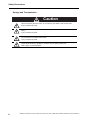
DANGER
Caution
Indicates an imminently hazardous situation which,
if not avoided, will result in death or serious injury.
Additionally, there may be severe property damage.
Indicates a potentially hazardous situation which,
if not avoided, may result in minor or moderate
injury, or property damage.
Even those items denoted by the caution symbol may lead to a serious outcome depending on the
situation. Accordingly, be sure to observe all safety precautions.
Precautions for Safe Use
Indicates precautions on what to do and what not to do to ensure using the product safely.
Precautions for Correct Use
Indicates precautions on what to do and what not to do to ensure proper operation and
performance.
Reference
Indicates an item that helps deepen your understanding of the product or other useful tip.
Explanation of Symbols
Example of symbols
This symbol indicates danger and caution.
The specific instruction is indicated using an illustration or text inside or near
The symbol shown to the left indicates “beware of electric shock.”
.
This symbol indicates a prohibited item (an item you must not do).
The specific instruction is indicated using an illustration or text inside or near
The symbol shown to the left indicates “disassembly prohibited,”
.
This symbol indicates a compulsory item (an item that must be done).
The specific instruction is indicated using an illustration or text inside or near
The symbol shown to the left indicates “grounding required,”
OMNUC G5-series AC Servomotors and Servo Drives User’s Manual (with Built-in EtherCAT Communications)
.
5
Safety Precautions
Precautions for Safe Use of This Product
Illustrations contained in this manual sometimes depict conditions without covers and safety shields for the
purpose of showing the details. When using this product, be sure to install the covers and shields as specified
and use the product according to this manual.
If the product has been stored for an extended period of time, contact your OMRON sales representative.
DANGER
Always connect the frame ground terminals of a 100 V or 200 V type drive and motor to a
type-D or higher ground. Always connect the ground terminals of a 400 V type to a type-C
or higher ground. Improper grounding may result in electrical shock.
Never touch the parts inside the Servo Drive.
Electric shock may result.
While the power is supplied, do not remove the front cover, terminal covers, cables, and
options.
Electric shock may result.
Installation, operation, and maintenance or inspection by unauthorized personnel is
prohibited.
Electric shock or injury may result.
Before carrying out wiring or inspection, turn OFF the power supply and wait for at least 15
minutes.
Electric shock may result.
Do not damage, pull, stress strongly, or pinch the cables or place heavy articles on them.
Electric shock, stopping of Servo Drive operation, or burn damage may result.
Never touch the rotating part of the Servomotor during operation.
Injury may result.
Never modify the Servo Drive.
Injury or equipment damage may result.
Install a stopping device on the machine to ensure safety.
* The holding brake is not a stopping device to ensure safety.
Injury may result.
Install an immediate stop device externally to the machine so that the operation can be
stopped and the power supply cut off immediately.
Injury may result.
When the power is restored after a momentary power interruption, the machine may restart
suddenly. Never come close to the machine when restoring power.
* Implement measures to ensure safety of people nearby even when the machine is
restarted.
Injury may result.
After an earthquake, be sure to conduct safety checks.
Electric shock, injury, or fire may result.
Never drive the Servomotor using an external drive source.
Fire may result.
6
OMNUC G5-series AC Servomotors and Servo Drives User’s Manual (with Built-in EtherCAT Communications)
Safety Precautions
DANGER
Do not place flammable materials near the Servomotor, Servo Drive, or Regeneration
Resistor.
Fire may result.
Install the Servomotor, Servo Drive, and Regeneration Resistor on non-flammable materials
such as metals.
Fire may result.
When you perform a system configuration using the safety function, be sure to fully
understand the relevant safety standards and the information in the operation manual, and
apply them to the system design.
Injury or damage may result.
Do not use the cable when it is laying in oil or water.
Electric shock, injury, or fire may result.
Never connect a commercial power supply directly to the Servomotor.
Fire or failure may result.
Do not perform wiring or any operation with wet hands.
Electric shock, injury, or fire may result.
Do not touch the key grooves with bare hands if a Servomotor with shaft-end key grooves is
being used.
Injury may result.
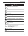
Caution
Use the Servomotor and Servo Drive in a specified combination.
Fire or equipment damage may result.
Do not store or install the Servo Drive in the following locations:
•
•
•
•
•
•
•
•
Location subject to direct sunlight
Location where the ambient temperature exceeds the specified level
Location where the relative humidity exceeds the specified level
Location subject to condensation due to rapid temperature changes
Location subject to corrosive or flammable gases
Location subject to high levels of dust, salt content, or iron dust
Location subject to splashes of water, oil, chemicals, etc.
Location where the Servo Drive may receive vibration or impact directly
Installing or storing the Servo Drive in any of these locations may result in fire, electric shock,
or equipment damage.
The Servo Drive radiator, Regeneration Resistor, Servomotor, etc., may become hot while
the power is supplied or remain hot for a while even after the power supply is cut off. Never
touch these components.
A burn injury may result.
OMNUC G5-series AC Servomotors and Servo Drives User’s Manual (with Built-in EtherCAT Communications)
7
Safety Precautions
Storage and Transportation
Caution
When transporting the Servo Drive, do not hold it by the cables or Servomotor shaft.
Injury or failure may result.
Do not overload the Servo Drive or Servomotor. (Follow the instructions on the product
label.)
Injury or failure may result.
Use the Servomotor eye-bolts only when transporting the Servomotor.
Do not use them to transport the machine.
Injury or failure may result.
When lifting a 15 kW or higher Servo Drive during moving or installation, always have two
people lift the product by grasping a metal part. Do not grasp a plastic part.
Risk of injury or product damage.
8
OMNUC G5-series AC Servomotors and Servo Drives User’s Manual (with Built-in EtherCAT Communications)
Safety Precautions
Installation and Wiring
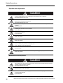
Caution
Do not step on the Servo Drive or place heavy articles on it.
Injury may result.
Do not block the intake or exhaust openings. Do not allow foreign objects to enter the Servo
Drive.
Fire may result.
Be sure to observe the mounting direction.
Failure may result.
Provide the specified clearance between the Servo Drive and the inner surface of the control
panel or other equipment.
Fire or failure may result.
Do not apply strong impact on the Servomotor shaft or Servo Drive.
Failure may result.
Wire the cables correctly and securely.
Runaway Servomotor, injury, or failure may result.
Securely tighten the mounting screws, terminal block screws, and cable screws.
Failure may result.
Use crimp terminals for wiring.
If simple twisted wires are connected directly to the protective ground terminal, fire may
result.
Only use the power supply voltage specified in this manual.
Burn damage may result.
In locations where the power supply infrastructure is poor, make sure the rated voltage can
be supplied.
Equipment damage may result.
Provide safety measures, such as a breaker, to protect against short circuiting of external
wiring.
Fire may result.
If the Servo Drive is used in the following locations, provide sufficient shielding measures.
•
•
•
•
Location subject to noise e.g., due to static electricity
Location subject to a strong electric or magnetic field
Location where exposure to radioactivity may occur
Location near power supply lines
Using the Servo Drive in any of these locations may result in equipment damage.
Connect an immediate stop relay in series with the brake control relay.
Injury or failure may result.
When connecting the battery, make sure the polarity is correct.
Battery damage or explosion may result.
OMNUC G5-series AC Servomotors and Servo Drives User’s Manual (with Built-in EtherCAT Communications)
9
Safety Precautions
Operation and Adjustment
Caution
Conduct a test operation after confirming that the equipment is not affected.
Equipment damage may result.
Before operating the Servo Drive in an actual environment, check if it operates correctly
based on the parameters you have set.
Equipment damage may result.
Never adjust or set parameters to extreme values, because it will make the operation
unstable.
Injury may result.
Separate the Servomotor from the mechanical system and check its operation before
installing the Servomotor to the machine.
Injury may result.
If an error occurs, remove the cause of the error and ensure safety, and then reset the alarm
and restart the operation.
Injury may result.
Do not use the built-in brake of the Servomotor for normal braking operation.
Failure may result.
Do not operate the Servomotor connected to an excessive load inertia.
Failure may result.
Install safety devices to prevent idling or locking of the electromagnetic brake or the gear
head, or leakage of grease from the gear head.
Injury, damage, or taint damage result.
If the Servo Drive fails, cut off the power supply to the Servo Drive at the power supply.
Fire may result.
Do not turn ON and OFF the main Servo Drive power supply frequently.
Failure may result.
Maintenance and Inspection
Caution
After replacing the Servo Drive, transfer to the new Servo Drive all data needed to resume
operation, before restarting operation.
Equipment damage may result.
Never repair the Servo Drive by disassembling it.
Electric shock or injury may result.
Be sure to turn OFF the power supply when the Servo Drive is not going to be used for a
prolonged period of time.
Injury may result.
10
OMNUC G5-series AC Servomotors and Servo Drives User’s Manual (with Built-in EtherCAT Communications)
Safety Precautions
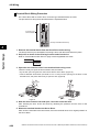
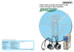
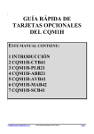
Location of Warning Label
The Servo Drive bears a warning label at the following location to provide handling warnings.
When handling the Servo Drive, be sure to observe the instructions provided on this label.
VOLT
AG IN
PHAS E 10PUT
0~12
E
FL
0V
1Ø
C
FREQ
2.6A
POWE
50/60
R
Hz
SERIA
L No
. A0
9080
OM
RO
004
N Co
rpo
ration
OU
TP
0-1 UT
20
3Ø V
1.7A
0~50
0.
100W 0Hz
MA
DE
IN JA
PAN
Warning label display location
(R88D-KN02H-ECT)
Instructions on Warning Label
Disposal
• When disposing of the battery, insulate it using tape, and dispose of it by following the applicable
ordinances of your local government.
• Dispose of the Servo Drive as industrial waste.
OMNUC G5-series AC Servomotors and Servo Drives User’s Manual (with Built-in EtherCAT Communications)
11
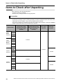
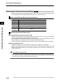
Items to Check after Unpacking
Items to Check after Unpacking
After unpacking, check the following items.
• Is this the model you ordered?
• Was there any damage sustained during shipment?
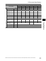
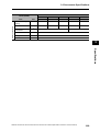
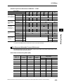
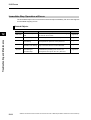
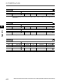
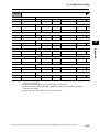
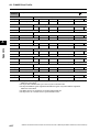
Accessories
Safety Precautions document x 1 copy
• Connectors, mounting screws, mounting brackets, and other accessories other than those in the
table below are not supplied. They must be prepared by the customer.
• If any item is missing or a problem is found such as Servo Drive damage, contact the OMRON
dealer or sales office where you purchased your product.
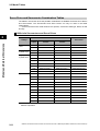
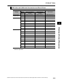
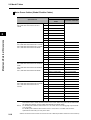
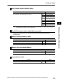
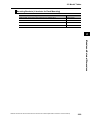
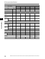
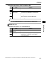
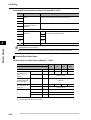
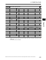
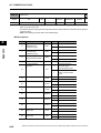
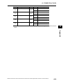
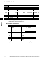
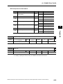
Specifications
Connector for main
circuit power supply
terminals and control
circuit power supply
terminals
Connector for External
Regeneration Resistor
connection terminals and
Motor connection
terminals
Safety bypass
connector
Mounting
Brackets
50 W
Singlephase
100 VAC
100 W
200 W
400 W
100 W
200 W
Singlephase/3phase
200 VAC
−
Included
400 W
750 W
1 kW
1.5 kW
2 kW
Included
3 kW
3-phase
200 VAC
5 kW
7.5 kW
−
Included
15 kW
600 W
1 kW
Included
−
1.5 kW
3-phase
400 VAC
2 kW
3 kW
5 kW
7.5 kW
−
Included
15 kW
12
OMNUC G5-series AC Servomotors and Servo Drives User’s Manual (with Built-in EtherCAT Communications)
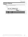
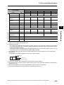
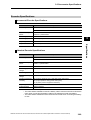
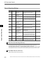
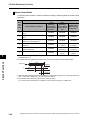
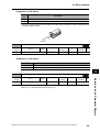
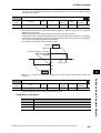
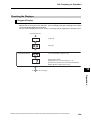
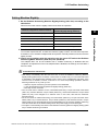
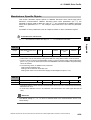
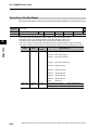
Revision History
Revision History
The manual revision code is a number appended to the end of the catalog number found in the
bottom left-hand corner of the front or back cover.
Example
Cat. No. I576-E1-01
Revision code
Revision
code
Revision Date
01
January 2011
Revised content
Original production
OMNUC G5-series AC Servomotors and Servo Drives User’s Manual (with Built-in EtherCAT Communications)
13
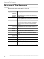
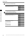
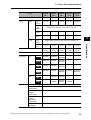
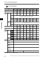
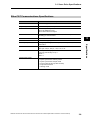
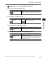
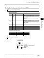
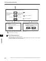
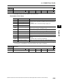
Structure of This Document
Structure of This Document
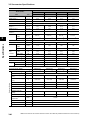
This manual consists of the following chapters.
Read the necessary chapter or chapters referring the following table.
Outline
Chapter 1
Features and
System
Configuration
This chapter explains the features of the Servo Drive, name of each
part, and applicable EC Directives and UL standards.
Chapter 2
Standard Models
and External
Dimensions
This chapter explains the models of Servo Drives, Servomotors, and
peripheral equipment, and provides the external dimensions and
mounting dimensions.
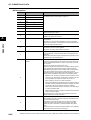
Chapter 3
Specifications
This chapter provides the general specifications, characteristics,
connector specifications, and I/O circuits of the Servo Drives as well as
the general specifications, characteristics, encoder specifications of
the Servomotors and other peripheral devices.
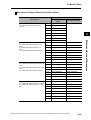
Chapter 4
System Design
This chapter explains the installation conditions for the Servo Drive,
Servomotor, and Decelerator, wiring methods including wiring
conforming to EMC Directives and regenerative energy calculation
methods as well as the performance of External Regeneration
Resistors.
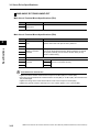
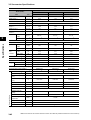
Chapter 5
EtherCAT
Communications
This chapter describes EtherCAT communications under the
assumption that the Servo Drive is connected to a CJ1W-NC281/
NC481/NC881/NCF81/NC482/NC882 Position Control Unit.
Chapter 6
Basic Control
Functions
This chapter describes the profile that is used to control the Servo
Drive.
Chapter 7
Applied
Functions
This chapter outlines the applied functions such as the electronic gear,
gain switching and soft start, and explains the settings.
Chapter 8
Safety Function
This chapter gives an outline of application functions, such as
electronic gears, gain switching, and soft start, and explains the
settings.
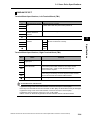
Chapter 9
Details on Servo
Parameters and
Objects
This chapter explains the set values and contents of each object.
Chapter 10 Operation
This chapter gives the operating procedures and explains how to
operate in each mode.
Chapter 11 Adjustment
Functions
This chapter explains the functions, setting methods, and items to note
regarding various gain adjustments.
Chapter 12 Troubleshooting This chapter explains the items to check when problems occur, error
and Maintenance diagnosis using the error display and measures, error diagnosis based
on the operating condition and measures, and periodic maintenance.
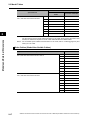
Appendix
14
The appendix provides a list of objects and EtherCAT terminology.
OMNUC G5-series AC Servomotors and Servo Drives User’s Manual (with Built-in EtherCAT Communications)
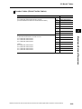
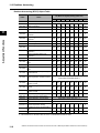
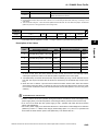
Table Of Contents
Introduction ............................................................................................1
Read and Understand this Manual ........................................................2
Safety Precautions.................................................................................5
Items to Check after Unpacking...........................................................12
Revision History...................................................................................13
Structure of This Document .................................................................14
Chapter 1 Features and System Configuration
1-1
Outline ................................................................................................... 1-1
Outline of the OMNUC G5 Series................................................................................ 1-1
Features of OMNUC G5-series Servo Drives.............................................................. 1-1
What Is EtherCAT?...................................................................................................... 1-2
Object Dictionary ......................................................................................................... 1-2
1-2
System Configuration ............................................................................ 1-3
1-3
Names and Functions............................................................................ 1-4
Servo Drive Part Names .............................................................................................. 1-4
Servo Drive Functions ................................................................................................. 1-5
1-4
System Block Diagram .......................................................................... 1-6
1-5
Applicable Standards........................................................................... 1-15
EC Directives............................................................................................................. 1-15
UL and cUL Standards .............................................................................................. 1-15
SEMI F47................................................................................................................... 1-15
Chapter 2 Models and External Dimensions
2-1
Servo System Configuration .................................................................. 2-1
2-2
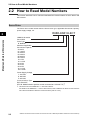
How to Read Model Numbers................................................................ 2-3
Servo Drive.................................................................................................................. 2-3
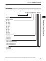
Servomotors ................................................................................................................ 2-4
2-3
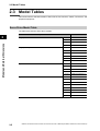
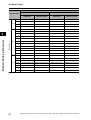
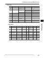
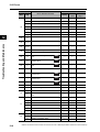
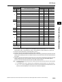
Model Tables ......................................................................................... 2-5
Servo Drive Model Table ............................................................................................. 2-5
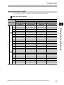
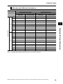
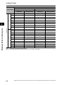
Servomotor Model Tables ........................................................................................... 2-6
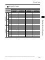
Servo Drive and Servomotor Combination Tables .................................................... 2-11
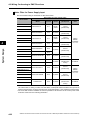
Cable and Peripheral Device Model Tables .............................................................. 2-13
2-4
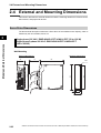
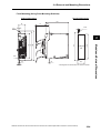
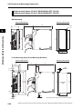
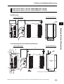
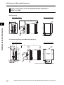
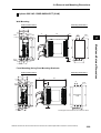
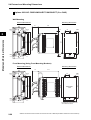
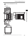
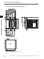
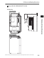
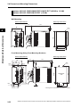
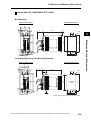
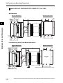
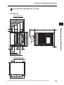
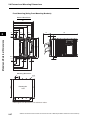
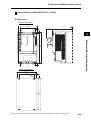
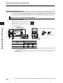
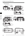
External and Mounting Dimensions ..................................................... 2-23
Servo Drive Dimensions ............................................................................................ 2-23
Servomotor Dimensions ............................................................................................ 2-39
External Regeneration Resistor Dimensions ............................................................. 2-66
2-5
EMC Filter Dimensions ........................................................................ 2-67
Chapter 3 Specifications
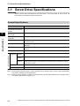
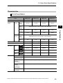
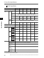
3-1
Servo Drive Specifications..................................................................... 3-1
General Specifications................................................................................................. 3-1
Characteristics............................................................................................................. 3-2
EtherCAT Communications Specifications .................................................................. 3-6
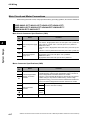
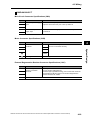
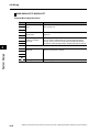
Main Circuit and Motor Connections ........................................................................... 3-7
16
OMNUC G5-series AC Servomotors and Servo Drives User’s Manual (with Built-in EtherCAT Communications)
Table Of Contents
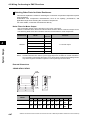
EtherCAT Communications Connector Specifications (RJ45) .................................. 3-16
Control I/O Connector Specifications (CN1).............................................................. 3-17
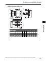
Control Input Circuits ................................................................................................. 3-20
Control Input Details .................................................................................................. 3-21
Control Output Circuits .............................................................................................. 3-23
Control Output Details ............................................................................................... 3-24
Encoder Connector Specifications (CN2).................................................................. 3-28
External Encoder Connector Specifications (CN4).................................................... 3-28
Analog Monitor Connector Specifications (CN5) ....................................................... 3-32
USB Connector Specifications (CN7)........................................................................ 3-33
Safety Connector Specifications (CN8) ..................................................................... 3-34
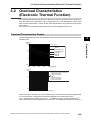
3-2
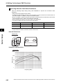
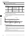
Overload Characteristics (Electronic Thermal Function) ......................3-36
Overload Characteristics Graphs .............................................................................. 3-36
3-3
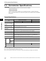
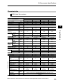
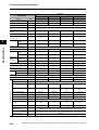
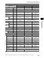
Servomotor Specifications....................................................................3-37
General Specifications............................................................................................... 3-37
Characteristics........................................................................................................... 3-38
Encoder Specifications .............................................................................................. 3-62
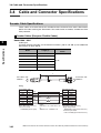
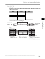
3-4
Cable and Connector Specifications ....................................................3-63
Encoder Cable Specifications.................................................................................... 3-63
Absolute Encoder Battery Cable Specifications ........................................................ 3-65
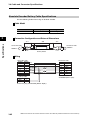
Motor Power Cable Specifications............................................................................. 3-66
Connector Specifications........................................................................................... 3-73
EtherCAT Communications Cable Specifications ..................................................... 3-76
Analog Monitor Cable Specifications......................................................................... 3-79
Control Cable Specifications ..................................................................................... 3-81
3-5
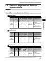
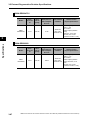
External Regeneration Resistor Specifications ....................................3-86
External Regeneration Resistor Specifications ......................................................... 3-86
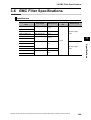
3-6
EMC Filter Specifications .....................................................................3-88
Chapter 4 System Design
4-1
Installation Conditions ............................................................................4-1
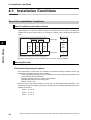
Servo Drive Installation Conditions.............................................................................. 4-1
Servomotor Installation Conditions.............................................................................. 4-2
Decelerator Installation Conditions.............................................................................. 4-5
4-2
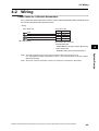
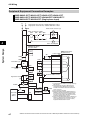
Wiring .....................................................................................................4-6
Peripheral Equipment Connection Examples .............................................................. 4-7
Main Circuit and Motor Connections ......................................................................... 4-17
4-3
Wiring Conforming to EMC Directives ..................................................4-30
Wiring Method ........................................................................................................... 4-30
Selecting Connection Component ............................................................................. 4-38
4-4
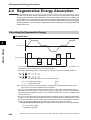
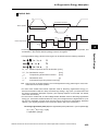
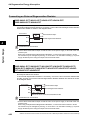
Regenerative Energy Absorption..........................................................4-49
Calculating the Regenerative Energy ........................................................................ 4-49
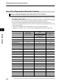
Servo Drive Regeneration Absorption Capacity ........................................................ 4-51
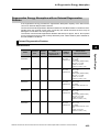
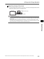
Regenerative Energy Absorption with an External Regeneration Resistor ............... 4-52
Connecting an External Regeneration Resistor ........................................................ 4-53
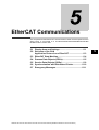
Chapter 5 EtherCAT Communications
5-1
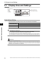
Display Area and Settings ......................................................................5-1
Node Address Setting.................................................................................................. 5-1
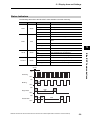
Status Indicators.......................................................................................................... 5-2
OMNUC G5-series AC Servomotors and Servo Drives User’s Manual (with Built-in EtherCAT Communications)
17
Table Of Contents
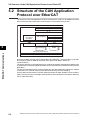
5-2
Structure of the CAN Application Protocol over EtherCAT .................... 5-3
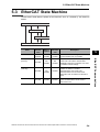
5-3
EtherCAT State Machine ....................................................................... 5-4
5-4
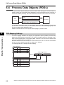
Process Data Objects (PDOs) ............................................................... 5-5
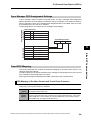
PDO Mapping Settings ................................................................................................ 5-5
Sync Manager PDO Assignment Settings ................................................................... 5-6
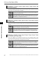
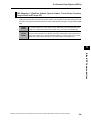
Fixed PDO Mapping .................................................................................................... 5-6
5-5
Service Data Objects (SDOs) ................................................................ 5-9
Abort Codes................................................................................................................. 5-9
5-6
Synchronization with Distributed Clocks.............................................. 5-10
Communications Cycle (DC Cycle) ........................................................................... 5-10
5-7
Emergency Messages ......................................................................... 5-11
Chapter 6 Basic Control Functions
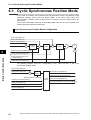
6-1
Cyclic Synchronous Position Mode ....................................................... 6-1
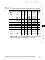
Related Objects ........................................................................................................... 6-2
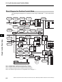
Block Diagram for Position Control Mode.................................................................... 6-3
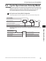
6-2
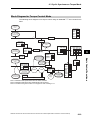
Cyclic Synchronous Velocity Mode........................................................ 6-4
Related Objects ........................................................................................................... 6-5
Objects Requiring Settings .......................................................................................... 6-5
Related Functions........................................................................................................ 6-5
Block Diagram for Speed Control Mode ...................................................................... 6-6
6-3
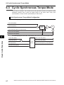
Cyclic Synchronous Torque Mode......................................................... 6-7
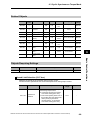
Related Objects ........................................................................................................... 6-8
Objects Requiring Settings .......................................................................................... 6-8
Related Functions........................................................................................................ 6-9
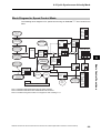
Block Diagram for Torque Control Mode ................................................................... 6-10
6-4
Homing Mode ...................................................................................... 6-11
6-5
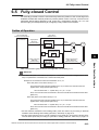
Fully-closed Control ............................................................................. 6-12
Outline of Operation .................................................................................................. 6-12
Objects Requiring Settings ........................................................................................ 6-13
Block Diagram for Fully-closed Control Mode ........................................................... 6-18
6-6
Connecting with OMRON Controllers .................................................. 6-19
Related Objects ......................................................................................................... 6-19
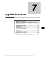
Chapter 7 Applied Functions
7-1
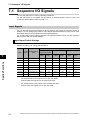
Sequence I/O Signals ............................................................................ 7-1
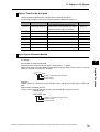
Input Signals................................................................................................................ 7-1
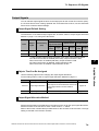
Output Signals ............................................................................................................. 7-4
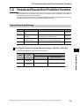
7-2
Forward and Reverse Drive Prohibition Functions ................................ 7-6
Objects Requiring Settings .......................................................................................... 7-6
7-3
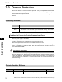
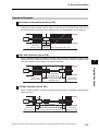
Overrun Protection................................................................................. 7-9
Operating Conditions................................................................................................... 7-9
Objects Requiring Settings .......................................................................................... 7-9
Operation Example.................................................................................................... 7-10
7-4
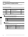
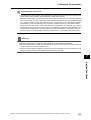
Backlash Compensation ...................................................................... 7-11
Objects Requiring Settings ........................................................................................ 7-11
18
OMNUC G5-series AC Servomotors and Servo Drives User’s Manual (with Built-in EtherCAT Communications)
Table Of Contents
7-5
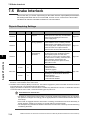
Brake Interlock......................................................................................7-13
Objects Requiring Settings ........................................................................................ 7-13
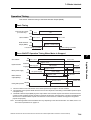
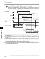
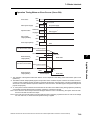
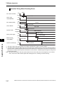
Operation Timing ....................................................................................................... 7-14
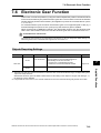
7-6
Electronic Gear Function ......................................................................7-18
Objects Requiring Settings ........................................................................................ 7-18
Operation Example.................................................................................................... 7-20
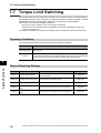
7-7
Torque Limit Switching .........................................................................7-21
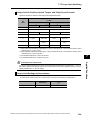
Operating Conditions................................................................................................. 7-21
Objects Requiring Settings ........................................................................................ 7-21
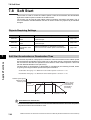
7-8
Soft Start...............................................................................................7-23
Objects Requiring Settings ........................................................................................ 7-23
Soft Start Acceleration or Deceleration Time ............................................................ 7-23
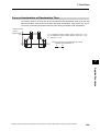
S-curve Acceleration or Deceleration Time ............................................................... 7-24
7-9
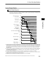
Gain Switching Function.......................................................................7-25
Objects Requiring Settings ........................................................................................ 7-26
Gain Switching Based on the Control Mode.............................................................. 7-27
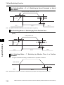
Diagrams of Gain Switching Setting .......................................................................... 7-32
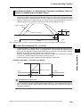
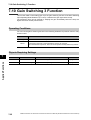
7-10 Gain Switching 3 Function....................................................................7-35
Operating Conditions................................................................................................. 7-35
Objects Requiring Settings ........................................................................................ 7-35
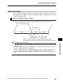
Operation Example.................................................................................................... 7-36
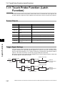
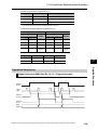
7-11 Touch Probe Function (Latch Function) ...............................................7-37
Related Objects ......................................................................................................... 7-37
Trigger Signal Settings .............................................................................................. 7-37
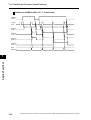
Operation Sequences................................................................................................ 7-38
Chapter 8 Safety Function
8-1
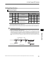
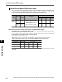
Safe Torque OFF Function.....................................................................8-1
I/O Signal Specifications.............................................................................................. 8-2
8-2
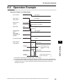
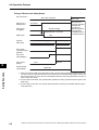
Operation Example.................................................................................8-4
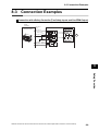
8-3
Connection Examples.............................................................................8-6
Chapter 9 Details on Servo Parameter Objects
9-1
Basic Settings.........................................................................................9-1
9-2
Gain Settings ..........................................................................................9-7
9-3
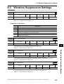
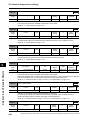
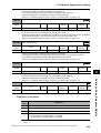
Vibration Suppression Settings ............................................................9-20
9-4
Analog Control Objects.........................................................................9-26
9-5
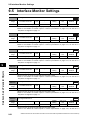
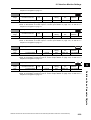
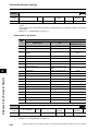
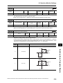
Interface Monitor Settings.....................................................................9-31
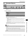
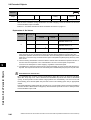
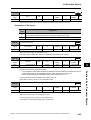
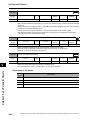
9-6
Extended Objects .................................................................................9-40
9-7
Special Objects.....................................................................................9-47
Chapter 10Operation
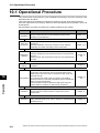
10-1 Operational Procedure .........................................................................10-1
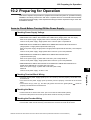
10-2 Preparing for Operation ........................................................................10-2
OMNUC G5-series AC Servomotors and Servo Drives User’s Manual (with Built-in EtherCAT Communications)
19
Table Of Contents
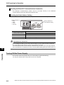
Items to Check Before Turning ON the Power Supply .............................................. 10-2
Turning ON the Power Supply ................................................................................... 10-3
Checking the Displays ............................................................................................... 10-4
Absolute Encoder Setup ............................................................................................ 10-6
Setting Up an Absolute Encoder from the CX-Drive.................................................. 10-6
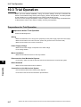
10-3 Trial Operation ..................................................................................... 10-7
Preparations for Trial Operation ................................................................................ 10-7
Test Operation via USB Communications from the CX-Drive ................................... 10-8
Chapter 11Adjustment Functions
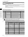
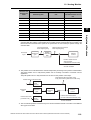
11-1 Analog Monitor..................................................................................... 11-1
Objects Requiring Settings ........................................................................................ 11-1
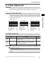
11-2 Gain Adjustment .................................................................................. 11-4
Purpose of the Gain Adjustment................................................................................ 11-4
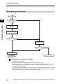
Gain Adjustment Methods ......................................................................................... 11-4
Gain Adjustment Procedure ...................................................................................... 11-5
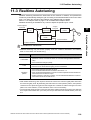
11-3 Realtime Autotuning ............................................................................ 11-6
Objects Requiring Settings ........................................................................................ 11-7
Setting Realtime Autotuning ...................................................................................... 11-7
Setting Machine Rigidity ............................................................................................ 11-8
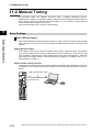
11-4 Manual Tuning ................................................................................... 11-13
Basic Settings.......................................................................................................... 11-13
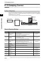
11-5 Damping Control................................................................................ 11-15
Outline of Operation ................................................................................................ 11-15
Objects Requiring Settings ...................................................................................... 11-15
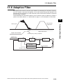
11-6 Adaptive Filter.................................................................................... 11-18
Objects Requiring Settings ...................................................................................... 11-19
Operating Procedure ............................................................................................... 11-20
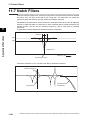
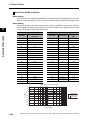
11-7 Notch Filters....................................................................................... 11-21
Objects Requiring Settings ...................................................................................... 11-22
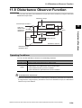
11-8 Disturbance Observer Function ......................................................... 11-24
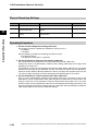
Operating Conditions............................................................................................... 11-24
Objects Requiring Settings ...................................................................................... 11-25
Operating Procedure ............................................................................................... 11-25
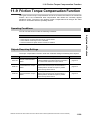
11-9 Friction Torque Compensation Function............................................ 11-26
Operating Conditions............................................................................................... 11-26
Objects Requiring Settings ...................................................................................... 11-26
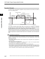
Operation Example.................................................................................................. 11-27
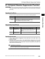
11-10 Hybrid Vibration Suppression Function ............................................ 11-28
Operating Conditions............................................................................................... 11-28
Objects Requiring Settings ...................................................................................... 11-28
Operating Procedure ............................................................................................... 11-28
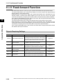
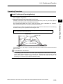
11-11 Feed-forward Function...................................................................... 11-29
Objects Requiring Settings ...................................................................................... 11-29
Operating Procedure ............................................................................................... 11-30
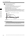
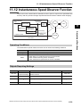
11-12 Instantaneous Speed Observer Function ......................................... 11-32
Operating Conditions............................................................................................... 11-32
20
OMNUC G5-series AC Servomotors and Servo Drives User’s Manual (with Built-in EtherCAT Communications)
Table Of Contents
Objects Requiring Settings ...................................................................................... 11-32
Operating Procedure ............................................................................................... 11-33
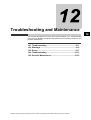
Chapter 12Troubleshooting and Maintenance
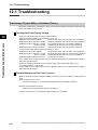
12-1 Troubleshooting....................................................................................12-1
Preliminary Checks When a Problem Occurs ........................................................... 12-1
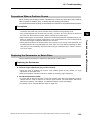
Precautions When a Problem Occurs ....................................................................... 12-2
Replacing the Servomotor or Servo Drive ................................................................. 12-2
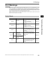
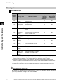
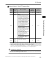
12-2 Warnings ..............................................................................................12-4
Related Objects ......................................................................................................... 12-4
Warning List............................................................................................................... 12-5
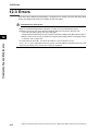
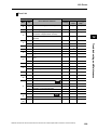
12-3 Errors....................................................................................................12-7
Immediate Stop Operation at Errors........................................................................ 12-11
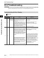
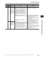
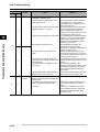
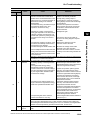
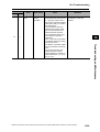
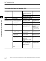
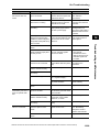
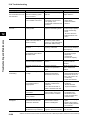
12-4 Troubleshooting..................................................................................12-13
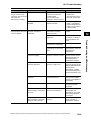
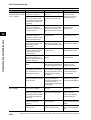
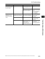
Troubleshooting with Error Displays........................................................................ 12-13
Troubleshooting Using the Operation State ............................................................ 12-27
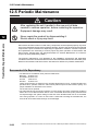
12-5 Periodic Maintenance .........................................................................12-33
Servomotor Life Expectancy.................................................................................... 12-33
Servo Drive Life Expectancy ................................................................................... 12-34
Replacing the Absolute Encoder Battery ................................................................ 12-35
Chapter A Appendix
A-1
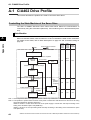
CiA402 Drive Profile .............................................................................. A-1
Controlling the State Machine of the Servo Drive........................................................A-1
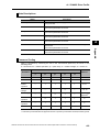
Modes of Operation .....................................................................................................A-4
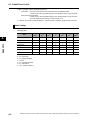
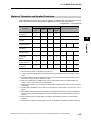
Communications Cycles and Corresponding Modes of Operation..............................A-4
Modes of Operation and Applied Functions ................................................................A-6
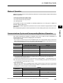
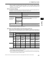
Changing the Mode of Operation ................................................................................A-7
Homing Mode Specifications .....................................................................................A-11
Object Dictionary .......................................................................................................A-17
Communication Objects ............................................................................................A-19
PDO Mapping Objects...............................................................................................A-25
Sync Manager Communication Objects ....................................................................A-34
Manufacturer Specific Objects...................................................................................A-38
Servo Drive Profile Object .........................................................................................A-43
Reserved Objects ......................................................................................................A-63
A-2
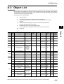
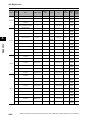
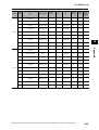
Object List............................................................................................ A-64
A-3
EtherCAT Terminology ........................................................................ A-81
Index
OMNUC G5-series AC Servomotors and Servo Drives User’s Manual (with Built-in EtherCAT Communications)
21
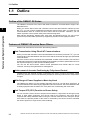
Features and System Configuration
This chapter explains the features of the Servo Drive, name of each part, and
applicable EC Directives and UL standards.
1-1 Outline ...........................................................................1-1
1-2 System Configuration ..................................................1-3
1-3 Names and Functions ..................................................1-4
1-4 System Block Diagram.................................................1-6
1-5 Applicable Standards .................................................1-15
OMNUC G5-series AC Servomotors and Servo Drives User’s Manual (with Built-in EtherCAT Communications)
1
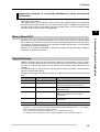
1-1 Outline
1-1 Outline
Outline of the OMNUC G5 Series
The OMNUC G5-series Servo Drives with Built-in EtherCAT Communications support 100Mbps EtherCAT.
When you use the Servo Drive with a Position Control Unit with EtherCAT interface (CJ1WNC@8@), you can create a sophisticated positioning control system. Also, you need only one
communications cable to connect the Servo Drive and the Controller. Therefore, you can
realize a position control system easily with reduced wiring effort.
With real time autotuning, adaptive filter, notch filter, and damping control, you can set up a
system that provides stable operation by suppressing vibration in low-rigidity machines.
Features and System Configuration
1
Features of OMNUC G5-series Servo Drives
OMNUC G5-series Servo Drives have the following features.
Data Transmission Using EtherCAT Communications
When you use it with a Position Control Unit with EtherCAT interface (CJ1W-NC@8@), you can
exchange all control data between the Servo Drive and the Controller through high-speed data
communications.
Since the various control commands are transmitted via data communications, Servomotor's
operational performance is maximized without being limited by interface specifications such as
the response frequency of the encoder feedback pulses.
You can use the Servo Drive's various control parameters and monitor data on a host
controller, and unify the system data for management.
Achievement of Accurate Positioning by Fully-closed Control
Feedback from the external encoder connected to the motor is used to accurately control
positioning. Position control is not affected by deviations caused by ball screws or temperature
changes.
Wide Range of Power Supplies to Meet Any Need
The OMNUC G5 Series now has models supporting 400 V for use with large equipment, at
overseas facilities and in wide-ranging applications and environment. Since the utilization ratio
of facility equipment also increases, the TCO (total cost of ownership) will come down.
Safe Torque OFF (STO) Function to Ensure Safety
You can cut off the motor current to stop the motor based on a signal from an emergency stop
button or other safety equipment. This can be used for an emergency stop circuit that is
compliant with safety standards without using an external contactor. Even during the torque
OFF status, the present position of the motor is monitored by the control circuits to eliminate
the need to perform an origin search when restarting.
1-1
OMNUC G5-series AC Servomotors and Servo Drives User’s Manual (with Built-in EtherCAT Communications)
1-1 Outline
Suppressing Vibration of Low-rigidity Mechanisms during Acceleration/
Deceleration
The damping control function suppresses vibration of low-rigidity mechanisms or devices
whose tips tend to vibrate.
Two damping filters are provided to enable switching the damping frequency automatically
according to the rotation direction and also via an external signal. In addition, the settings can
be made easily by setting the damping frequency and filter values. You are assured of stable
operation even if the set values are inappropriate.
1
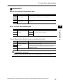
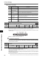
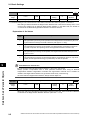
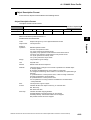
What Is EtherCAT?
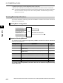
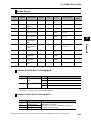
Object Dictionary
OMNUC G5-series Servo Drives with Built-in EtherCAT Communications use the object
dictionary for CAN application protocol over EtherCAT (CoE) as a base for communications.
An object is a special data structure inside a device that consists of data, parameters, and
methods.
An object dictionary is a data structure that describes the data type objects, communications
objects, and application objects.
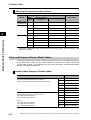
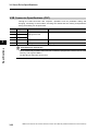
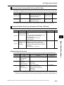
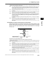
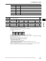
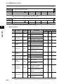
All objects are assigned four-digit hexadecimal numbers in the areas shown in the following
table.
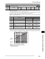
Indexes
Area
Contents
0000 to 0FFF hex
Data Type Area
Definitions of data types.
1000 to 1FFF hex
CoE Communications Area
Definitions of variables that can be used by all
servers for designated communications.
2000 to 2FFF hex
Manufacturer Specific Area 1
Variables with common definitions for all
OMRON products.
3000 to 5FFF hex
Manufacturer Specific Area 2
Variables with common definitions for all
OMNUC G5-series Servo Drives (servo
parameters).*1
6000 to 9FFF hex
Device Profile Area
Variables defined in the Servo Drive's CiA402
drive profile.
A000 to FFFF hex
Reserved Area
Area reserved for future use.
*1 OMNUC G5-series Servo Drive parameters (Pn@@@) are allocated to objects 3000 to 3999 hex.
Indexes 3@@@ hex correspond to OMNUC G5-series Servo Drive parameters Pn@@@. For example,
object 3504 hex is the same as parameter Pn504.
Pn@@@ uses decimal numbers but object 3@@@ is a hexadecimal number.
For details on servo parameters, refer to Chapter 9 Details on Servo Parameter Objects.
OMNUC G5-series AC Servomotors and Servo Drives User’s Manual (with Built-in EtherCAT Communications)
1-2
Features and System Configuration
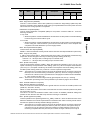
EtherCAT is an open high-speed industrial network system that conforms to Ethernet (IEEE
802.3). Each node achieves a short cycle time by transmitting Ethernet frames at high speed.
A mechanism that allows sharing clock information enables high-precision synchronization
control with low communications jitter.
EtherCAT is a registered trademark of Beckhoff Automation Gmbh (Germany). EtherCAT
technology is protected by patents.
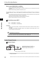
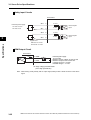
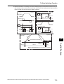
1-2 System Configuration
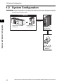
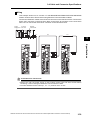
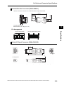
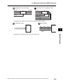
1-2 System Configuration
The system configuration for a OMNUC G5-Series AC Servo Drive with Built-in EtherCAT
Communications is shown below.
Controller (EtherCAT
(EtherCAT)
1
Features and System Configuration
EtherCAT
Programmable Controller
SYSMAC CJ2
Position Control Unit
CJ1W-NC@8@
OMNUC G5 Series
AC Servo Drive
R88D-KN@-ECT
INC
NC
ABS
BS
OMNUC G5 Series
AC Servomotor
R88M-K@
1-3
OMNUC G5-series AC Servomotors and Servo Drives User’s Manual (with Built-in EtherCAT Communications)
1-3 Names and Functions
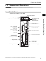
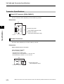
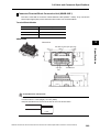
1-3 Names and Functions
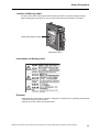
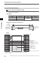
This section describes the names and functions of Servo Drive parts.
Servo Drive Part Names
The Servo Drive part names are given below.
1
EtherCAT status indicators
Seven-segment display
Features and System Configuration
Analog monitor connector (CN5)
ADR
Rotary switches for node
address setting
USB connector (CN7)
EtherCAT communications
connector: ECAT IN
Main circuit
power supply terminals
(L1, L2, and L3)
Control circuit
power supply terminals
(L1C and L2C)
EtherCAT communications
connector: ECAT OUT
Safety connector (CN8)
Charge lamp
Control I/O connector (CN1)
External Regeneration
Resistor connection
terminals (B1, B2, and B3)
Motor connection
terminals (U, V, and W)
External encoder
connector (CN4)
Protective ground terminals
Encoder connector (CN2)
OMNUC G5-series AC Servomotors and Servo Drives User’s Manual (with Built-in EtherCAT Communications)
1-4
1-3 Names and Functions
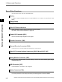
Servo Drive Functions
The functions of each part are described below.
Display
A 2-digit 7-segment display shows the node address, error codes, and other Servo Drive
status.
1
Charge Lamp
Features and System Configuration
Lights when the main circuit power supply is turned ON.
EtherCAT Status Indicators
These indicators show the status of EtherCAT communications.
For details, refer to Status Indicators on page 5-2.
Control I/O Connector (CN1)
Used for command input signals and I/O signals.
Encoder Connector (CN2)
Connector for the encoder installed in the Servomotor.
External Encoder Connector (CN4)
Connector for an encoder signal used during fully-closed control.
EtherCAT Communications Connectors (ECAT IN and ECAT OUT)
These connectors are for EtherCAT communications.
Analog Monitor Connector (CN5)
You can use a special cable to monitor values, such as the motor rotation speed, torque
command value, etc.
USB Connector (CN7)
Communications connector for the computer.
Safety Connector (CN8)
Connector for safety devices.
If no safety devices are used, keep the factory-set safety bypass connector installed.
1-5
OMNUC G5-series AC Servomotors and Servo Drives User’s Manual (with Built-in EtherCAT Communications)
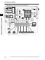
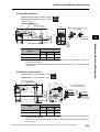
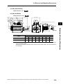
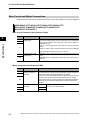
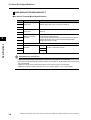
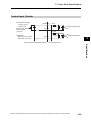
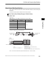
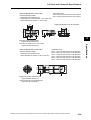
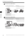
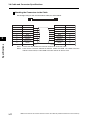
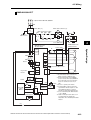
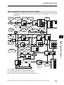
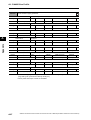
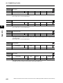
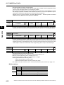
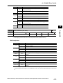
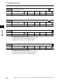
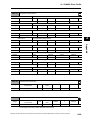
1-4 System Block Diagram
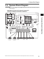
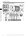
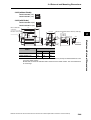
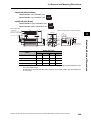
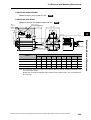
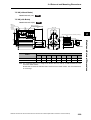
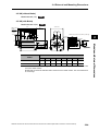
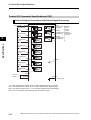
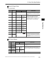
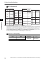
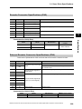
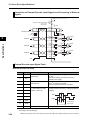
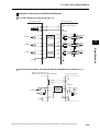
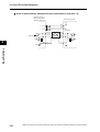
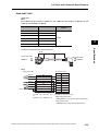
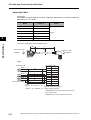
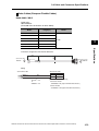
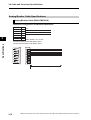
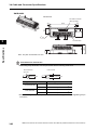
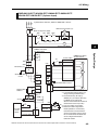
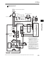
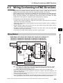
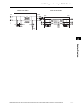
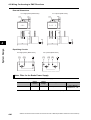
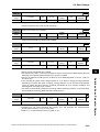
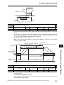
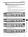
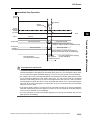
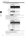
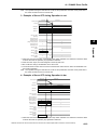
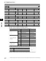
1-4 System Block Diagram
This is the block diagram of the OMNUC G5-series AC Servo Drive with Built-in EtherCAT
Communications.
R88D-KNA5L-ECT/-KN01L-ECT/-KN02L-ECT/-KN04L-ECT/
-KN01H-ECT/-KN02H-ECT/-KN04H-ECT/-KN08H-ECT
L1
CN A
FUSE
L2
CN B
B1
1
B2
−
FUSE
L2C
U
V
W
Voltage
detection
+
−
GR
GR
15 V
G1
5V
3.3 V
2.5 V
1.5 V
E5 V
±12 V
G2
SW power
supply main
circuit control
Internal
control power
supply
Relay
drive
Regeneration
control
Overcurrent
detection
Current detection
Gate drive
Display and
setting circuit
area
MPU & ASIC
Position, speed, and torque calculation control area
• PWM control
ECAT
ECAT
CN1
CN2
IN
OUT
Encoder
Control
EtherCAT
EtherCAT
communications communications interface
connector
connector
CN4
CN5
CN7
CN8
External
encoder
Analog
monitor
USB
Safety
OMNUC G5-series AC Servomotors and Servo Drives User’s Manual (with Built-in EtherCAT Communications)
1-6
Features and System Configuration
L3
L1C
B3
+
FUSE
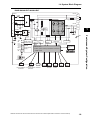
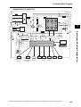
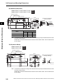
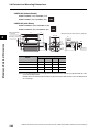
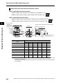
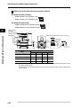
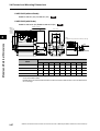
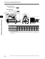
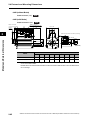
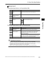
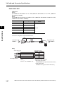
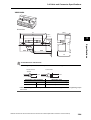
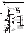
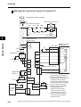
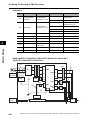
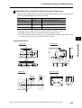
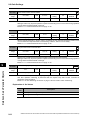
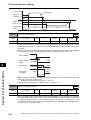
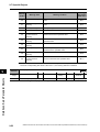
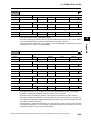
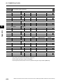
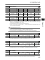
1-4 System Block Diagram
R88D-KN10H-ECT/-KN15H-ECT/-KN20H-ECT
L1
CN B
CN A
FUSE
B2
B3
+
Internal Regeneration
Resistor
L2
L3
1
FUSE
L1C
−
FUSE
U
V
W
Voltage
detection
+
L2C
Features and System Configuration
B1
−
GR
GR
15 V
G1
SW power
supply main
circuit control
5V
3.3 V
2.5 V
1.5 V
E5 V
±12 V
G2
Internal
control power
supply
Relay
drive
Regeneration
control
Overcurrent
detection
Current detection
Gate drive
Display and
setting circuit
area
MPU & ASIC
Position, speed, and torque calculation control area
• PWM control
Axial-flow fan
ECAT
ECAT
CN1
CN2
CN4
IN
OUT
EtherCAT
Control Encoder External
EtherCAT
communications communications interface
encoder
connector
connector
1-7
CN5
CN7
CN8
Analog
monitor
USB
Safety
OMNUC G5-series AC Servomotors and Servo Drives User’s Manual (with Built-in EtherCAT Communications)
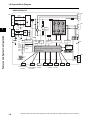
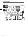
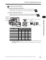
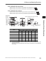
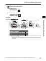
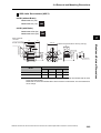
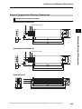
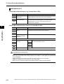
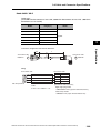
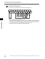
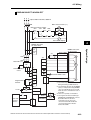
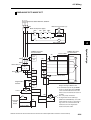
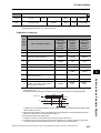
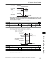
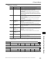
1-4 System Block Diagram
R88D-KN30H-ECT/-KN50H-ECT
CN C
CN A
FUSE
L1
B2
B3
+
Internal Regeneration Resistor
L2
L3
B1
NC
FUSE
L1C
−
FUSE
L2C
CN B
U
V
W
Voltage
detection
+
1
−
GR
15 V
G1
SW power
supply main
circuit control
5V
3.3 V
2.5 V
1.5 V
E5 V
±12 V
G2
Internal
control power
supply
Relay
drive
Regeneration
control
Overcurrent
detection
Current detection
Gate drive
Display and
setting circuit
area
MPU & ASIC
Position, speed, and torque calculation control area
• PWM control
Axial-flow fan
ECAT
ECAT
CN1
CN2
CN4
IN
OUT
Control Encoder External
EtherCAT
EtherCAT
communications communications interface
encoder
connector
connector
CN5
CN7
CN8
Analog
monitor
USB
Safety
OMNUC G5-series AC Servomotors and Servo Drives User’s Manual (with Built-in EtherCAT Communications)
1-8
Features and System Configuration
GR
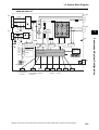
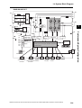
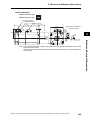
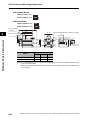
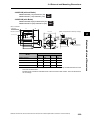
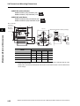
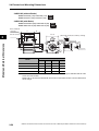
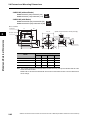
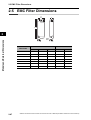
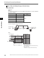
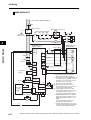
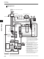
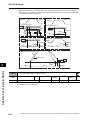
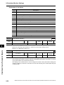
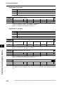
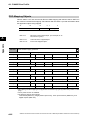
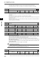
1-4 System Block Diagram
R88D-KN75H-ECT
TB1
TB1
B1
FUSE
L1
B2
NC
+
L2
L3
1
Fuse
FUSE
−
Voltage
detection
TB2
L1C
FUSE
+
Features and System Configuration
L2C
GR
−
15 V
G1
SW power
supply main
circuit control
5V
3.3 V
2.5 V
1.5 V
E5 V
±12 V
G2
Internal
control power
supply
Relay
drive
Regeneration
control
Overcurrent
detection
Current detection
Gate drive
GR
Display and
setting circuit
area
MPU & ASIC
Position, speed, and torque calculation control area
• PWM control
DB1
DB2
DB3
DB4
Axial-flow fan × 3
ECAT
ECAT
CN1
CN2
CN4
IN
OUT
External
Control
Encoder
EtherCAT
EtherCAT
communications communications interface
encoder
connector
connector
1-9
TB1
U
V
W
CN5
Analog
monitor
CN7
CN8
USB
Safety
OMNUC G5-series AC Servomotors and Servo Drives User’s Manual (with Built-in EtherCAT Communications)
TB2
1-4 System Block Diagram
R88D-KN150H-ECT
TB2
TB2
B1
FUSE
L1
B2
NC
+
Fuse
L2
L3
FUSE
TB1
L1C
−
FUSE
L2C
U
V
W
Voltage
detection
+
TB2
1
−
GR
15 V
G1
SW power
supply main
circuit control
5V
3.3 V
2.5 V
1.5 V
E5 V
±12 V
G2
Internal
control power
supply
Relay
drive
Regeneration
control
Overcurrent
detection
Current detection
Gate drive
MPU & ASIC
Position, speed, and torque calculation control area
Display and
setting circuit
area
• PWM control
DB1 TB1
DB2
Axial-flow fan × 4
ECAT
ECAT
CN1
CN2
CN4
IN
OUT
Encoder
External
Control
EtherCAT
EtherCAT
communications communications interface
encoder
connector
connector
CN5
CN7
CN8
Analog
monitor
USB
Safety
OMNUC G5-series AC Servomotors and Servo Drives User’s Manual (with Built-in EtherCAT Communications)
1-10
Features and System Configuration
GR
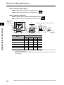
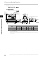
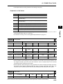
1-4 System Block Diagram
R88D-KN06F-ECT/-KN10F-ECT/-KN15F-ECT/-KN20F-ECT
L1
CN D
CN A
FUSE
B2
B3
+
Internal Regeneration Resistor
L2
NC
FUSE
L3
1
−
CN B
CN C
24 V
FUSE
Voltage
detection
+
U
V
W
+
DC-DC
−
−
0V
Features and System Configuration
B1
GR
GR
15 V
G1
SW power
supply main
circuit control
Relay
drive
5V
3.3 V
2.5 V
1.5 V
E5 V
±12 V
G2
Internal
control power
supply
MPU & ASIC
Regeneration
control
Overcurrent
detection
Current detection
Gate drive
Display and
setting circuit
area
Position, speed, and torque calculation control area
• PWM control
Axial-flow fan
ECAT
ECAT
CN1
IN
OUT
Control
EtherCAT
EtherCAT
communications communications interface
connector
connector
1-11
CN2
CN4
Encoder External
encoder
CN5
Analog
monitor
CN7
CN8
USB
Safety
OMNUC G5-series AC Servomotors and Servo Drives User’s Manual (with Built-in EtherCAT Communications)
1-4 System Block Diagram
R88D-KN30F-ECT/-KN50F-ECT
CN D
CN A
FUSE
L1
B2
+
Internal Regeneration Resistor
L2
L3
B3
NC
FUSE
−
CN B
CN C
24 V
B1
FUSE
Voltage
detection
+
+
DC-DC
−
−
0V
U
V
W
1
GR
15 V
G1
SW power
supply main
circuit control
Relay
drive
5V
3.3 V
2.5 V
1.5 V
E5 V
±12 V
G2
Internal
control power
supply
MPU & ASIC
Regeneration
control
Overcurrent
detection
Current detection
Gate drive
Display and
setting circuit
area
Position, speed, and torque calculation control area
• PWM control
Axial-flow fan
ECAT
ECAT
CN1
CN2
CN4
IN
OUT
EtherCAT
Control Encoder External
EtherCAT
communications communications interface
encoder
connector
connector
CN5
Analog
monitor
CN7
USB
CN8
Safety
OMNUC G5-series AC Servomotors and Servo Drives User’s Manual (with Built-in EtherCAT Communications)
1-12
Features and System Configuration
GR
1-4 System Block Diagram
R88D-KN75F-ECT
TB1
TB1
B1
FUSE
L1
B2
NC
+
L2
L3
1
Fuse
FUSE
−
Voltage
detection
TB2
24 V
FUSE
+
+
DC-DC
−
−
Features and System Configuration
0V
GR
15 V
G1
SW power
supply main
circuit control
5V
3.3 V
2.5 V
1.5 V
E5 V
±12 V
G2
Internal
control power
supply
Relay
drive
Regeneration
control
Overcurrent
detection
Current detection
Gate drive
GR
Display and
setting circuit
area
MPU & ASIC
Position, speed, and torque calculation control area
• PWM control
DB1
DB2
DB3
DB4
Axial-flow fan × 3
ECAT
ECAT
CN1
CN2
CN4
IN
OUT
External
Control
Encoder
EtherCAT
EtherCAT
communications communications interface
encoder
connector
connector
1-13
TB1
U
V
W
CN5
CN7
CN8
Analog
monitor
USB
Safety
OMNUC G5-series AC Servomotors and Servo Drives User’s Manual (with Built-in EtherCAT Communications)
TB2
1-4 System Block Diagram
R88D-KN150F-ECT
TB2
TB2
B1
FUSE
L1
+
L2
L3
TB1
24 V
B2
NC
Fuse
FUSE
−
FUSE
Voltage
detection
+
+
DC-DC
−
−
0V
U
V
W
TB2
1
GR
15 V
G1
SW power
supply main
circuit control
5V
3.3 V
2.5 V
1.5 V
E5 V
±12 V
G2
Internal
control power
supply
Relay
drive
Regeneration
control
Overcurrent
detection
Current detection
Gate drive
Display and
setting circuit
area
MPU & ASIC
Position, speed, and torque calculation control area
• PWM control
DB1 TB1
DB2
Axial-flow fan × 4
ECAT
ECAT
CN1
CN2
CN4
IN
OUT
EtherCAT
EtherCAT
Control Encoder External
communications communications interface
encoder
connector
connector
CN5
CN7
CN8
Analog
monitor
USB
Safety
OMNUC G5-series AC Servomotors and Servo Drives User’s Manual (with Built-in EtherCAT Communications)
1-14
Features and System Configuration
GR
1-5 Applicable Standards
1-5 Applicable Standards
This section describes applicable EMC Directives.
EC Directives
Features and System Configuration
1
EC
Directive
Product
Applicable standards
Low
Voltage
Directive
AC Servo Drives
EN 61800-5-1
AC Servomotors
EN 60034-1/-5
EMC
Directive
AC Servo Drives
AC Servomotors
EN 55011 class A group 1
IEC 61800-3
EN 61000-6-2
Machinery
Directive
AC Servo Drives
EN 954-1 (Category 3)
EN ISO 13849-1: 2008 (Category 3) (PLc, d)
ISO 13849-1: 2006 (Category 3) (PLc, d)
EN 61508 (SIL 2)
EN 62061 (SIL 2)
EN 61800-5-2 (STO)
IEC 61326-3-1 (SIL 2)
Note: To conform to EMC Directives, the Servomotor and Servo Drive must be installed under the conditions described
in 4-3 Wiring Conforming to EMC Directives on page 4-30.
UL and cUL Standards
Standard
UL
standards
CSA
standards
Product
Applicable standards
File number
AC Servo Drives
UL 508C
E179149
AC Servomotors
UL 1004-1
E331224
UL 1004-1, UL 1004-6
E327868*1
AC Servo Drives
CSA 22.2 No. 14
E179149
AC Servomotors
CSA 22.2 No. 100
E331224
CSA 22.2 No. 100
E327868*1
*1: Applies to 2,000-r/min Servomotors of 7.5 to 15 kW and 1,000-r/min Servomotors of 4.5 to 6 kW.
SEMI F47
Some Servo Drives conform to the SEMI F47 standard for momentary power interruptions
(voltage sag immunity) for no-load or light-load operation.
This standard applies to semiconductor manufacturing equipment.
Note 1. It does not apply to Servo Drivers with single-phase 100-V specifications or with 24-VDC
specifications for the control power input.
Note 2. Always perform evaluation testing for SEMI F47 compliance in the actual system.
1-15
OMNUC G5-series AC Servomotors and Servo Drives User’s Manual (with Built-in EtherCAT Communications)
Models and External
Dimensions
This chapter explains the models of Servo Drive, Servomotor, and peripheral
devices, and provides the external dimensions and mounting dimensions.
2-1
2-2
2-3
2-4
2-5
Servo System Configuration .......................................2-1
How to Read Model Numbers ......................................2-3
Model Tables .................................................................2-5
External and Mounting Dimensions..........................2-23
EMC Filter Dimensions...............................................2-67
OMNUC G5-series AC Servomotors and Servo Drives User’s Manual (with Built-in EtherCAT Communications)
2
2-1 Servo System Configuration
2-1 Servo System Configuration
Controller
SYSMAC PLC Position Control Unit with EtherCAT Interface
Programmable
Controller
SYSMAC CJ2
Support Software
● CX-One FA Integrated
Tool Package
(Including CX-Drive)
● CX-Drive
WS02-DRVC1
Position Control Unit (NC)
CJ1W-NC@8@
Models and External Dimensions
2
Support Software
● CX-One FA Integrated
Tool Package
CX-Programmer,
CX-Position,
and CX-Motion
2-1
OMNUC G5-series AC Servomotors and Servo Drives User’s Manual (with Built-in EtherCAT Communications)
2-1 Servo System Configuration
AC Servomotors
AC Servo Drive
Motor power signals
Power Cables
USB
communications
● Flexible Cables
• Without Brake
R88A-CA@@@@@SR-E
• With Brake
R88A-CA@@@@@BR-E
2
EtherCAT
communications
Brake Cables (50 to 750 W max.)
Feedback Signals
Encoder Cables
● OMNUC G5-series Servo Drive
● Flexible Cables
• 750 W or less:
R88A-CRKA@@@CR-E
• 1 kW or more:
R88A-CRKC@@@NR-E
R88D-KN@-ECT
100 VAC
200 VAC
400 VAC
Peripheral Devices
● External
External
encoder
Regeneration
Resistors
R88A-RR
● OMNUC G5-series Servomotor
R88M-K
3000 r/min
2000 r/min
1000 r/min
Absolute Encoder Battery Cable
R88A-CRGD0R3C (-BS)
(A battery is included with model
numbers ending in “BS.”)
* Not required if a battery is connected to
the control connector (CN1).
OMNUC G5-series AC Servomotors and Servo Drives User’s Manual (with Built-in EtherCAT Communications)
2-2
Models and External Dimensions
● Flexible Cable
R88A-CAKA@@@BR-E
2-2 How to Read Model Numbers
2-2 How to Read Model Numbers
This section describes how to read and understand the model numbers of Servo Drives and
Servomotors.
Servo Drive
The Servo Drive model number tells the Servo Drive type, applicable Servomotor capacity,
power supply voltage, etc.
R88D-KN01H-ECT
2
Models and External Dimensions
OMNUC G5-series
Servo Drive
Drive Type
N: Network
Maximum Applicable
Servomotor Capacity
A5: 50 W
01: 100 W
02: 200 W
04: 400 W
06: 600 W
08: 750 W
10: 1 kW
15: 1.5 kW
20: 2 kW
30: 3 kW
50: 5 kW
75: 7.5 kW
150: 15 kW
Power Supply Voltage
L: 100 VAC
H: 200 VAC
F: 400 VAC
Communications Type
ECT: EtherCAT
(ETC-R: Model limited to position control connected to CJ1W-NC@8@)*1
*1. This manual is for the R88D-KN@@@-ECT Servo Drives.
For details on the R88D-KN@@@-ECT-R Servo Drives, refer to OMNUC G5 Series AC Servomotors/
Servo Drives with Built-in EtherCAT Communications (Cat. No. I573).
2-3
OMNUC G5-series AC Servomotors and Servo Drives User’s Manual (with Built-in EtherCAT Communications)
2-2 How to Read Model Numbers
Servomotors
The model number provides information such as the Servomotor type, motor capacity, rated
rotation speed, and power supply voltage.
R88M-KP10030H-BOS2
OMNUC G5-series Servomotor
2
Motor Type
Blank: Cylinder type
Servomotor Capacity
Models and External Dimensions
050: 50 W
100: 100 W
200: 200 W
400: 400 W
600: 600 W
750: 750 W
900: 900 W
1K0: 1 kW
1K5: 1.5 kW
2K0: 2 kW
3K0: 3 kW
4K0: 4 kW
4K5: 4.5 kW
5K0: 5 kW
6K0: 6 kW
7K5: 7.5 kW
11K0: 11 kW
15K0: 15 kW
Rated Rotation Speed
10: 1,000 r/min
15: 1,500 r/min
20: 2,000 r/min
30: 3,000 r/min
Applied Voltage
F:
H:
L:
C:
T:
S:
400 VAC (incremental encoder)
200 VAC (incremental encoder)
100 VAC (incremental encoder)
400 VAC (absolute encoder)
200 VAC (absolute encoder)
100 VAC (absolute encoder)
Options
No:
B:
O:
S2:
Straight shaft
With brake
With oil seal
With key and tap
OMNUC G5-series AC Servomotors and Servo Drives User’s Manual (with Built-in EtherCAT Communications)
2-4
2-3 Model Tables
2-3 Model Tables
This section lists the standard models of Servo Drives, Servomotors, Cables, Connectors, and
peripheral equipment.
Servo Drive Model Table
The table below lists the Servo Drive models.
Specifications
2
Models and External Dimensions
Single-phase 100 VAC
Single-phase/3-phase 200 VAC
3-phase 200 VAC
3-phase 400 VAC
2-5
Model
50 W
R88D-KNA5L-ECT
100 W
R88D-KN01L-ECT
200 W
R88D-KN02L-ECT
400 W
R88D-KN04L-ECT
100 W
R88D-KN01H-ECT
200 W
R88D-KN02H-ECT
400 W
R88D-KN04H-ECT
750 W
R88D-KN08H-ECT
1 kW
R88D-KN10H-ECT
1.5 kW
R88D-KN15H-ECT
2 kW
R88D-KN20H-ECT
3 kW
R88D-KN30H-ECT
5 kW
R88D-KN50H-ECT
7.5 kW
R88D-KN75H-ECT
15 kW
R88D-KN150H-ECT
600 W
R88D-KN06F-ECT
1 kW
R88D-KN10F-ECT
1.5 kW
R88D-KN15F-ECT
2 kW
R88D-KN20F-ECT
3 kW
R88D-KN30F-ECT
5 kW
R88D-KN50F-ECT
7.5 kW
R88D-KN75F-ECT
15 kW
R88D-KN150F-ECT
OMNUC G5-series AC Servomotors and Servo Drives User’s Manual (with Built-in EtherCAT Communications)
2-3 Model Tables
Servomotor Model Tables
The following tables list the Servomotor models by the rated motor speed.
3,000-r/min Servomotors
Model
Specifications
Without brakes
200 V
400 V
With absolute encoder
Straight shaft
without key
Straight shaft
with key and tap
Straight shaft
without key
Straight shaft
with key and tap
50 W
R88M-K05030H
R88M-K05030H-S2
R88M-K05030T
R88M-K05030T-S2
100 W
R88M-K10030L
R88M-K10030L-S2
R88M-K10030S
R88M-K10030S-S2
200 W
R88M-K20030L
R88M-K20030L-S2
R88M-K20030S
R88M-K20030S-S2
400 W
R88M-K40030L
R88M-K40030L-S2
R88M-K40030S
R88M-K40030S-S2
50 W
R88M-K05030H
R88M-K05030H-S2
R88M-K05030T
R88M-K05030T-S2
100 W
R88M-K10030H
R88M-K10030H-S2
R88M-K10030T
R88M-K10030T-S2
200 W
R88M-K20030H
R88M-K20030H-S2
R88M-K20030T
R88M-K20030T-S2
400 W
R88M-K40030H
R88M-K40030H-S2
R88M-K40030T
R88M-K40030T-S2
750 W
R88M-K75030H
R88M-K75030H-S2
R88M-K75030T
R88M-K75030T-S2
1 kW
R88M-K1K030H
R88M-K1K030H-S2
R88M-K1K030T
R88M-K1K030T-S2
1.5 kW
R88M-K1K530H
R88M-K1K530H-S2
R88M-K1K530T
R88M-K1K530T-S2
2 kW
R88M-K2K030H
R88M-K2K030H-S2
R88M-K2K030T
R88M-K2K030T-S2
3 kW
R88M-K3K030H
R88M-K3K030H-S2
R88M-K3K030T
R88M-K3K030T-S2
4 kW
R88M-K4K030H
R88M-K4K030H-S2
R88M-K4K030T
R88M-K4K030T-S2
5 kW
R88M-K5K030H
R88M-K5K030H-S2
R88M-K5K030T
R88M-K5K030T-S2
750 W
R88M-K75030F
R88M-K75030F-S2
R88M-K75030C
R88M-K75030C-S2
1 kW
R88M-K1K030F
R88M-K1K030F-S2
R88M-K1K030C
R88M-K1K030C-S2
1.5 kW
R88M-K1K530F
R88M-K1K530F-S2
R88M-K1K530C
R88M-K1K530C-S2
2 kW
R88M-K2K030F
R88M-K2K030F-S2
R88M-K2K030C
R88M-K2K030C-S2
3 kW
R88M-K3K030F
R88M-K3K030F-S2
R88M-K3K030C
R88M-K3K030C-S2
4 kW
R88M-K4K030F
R88M-K4K030F-S2
R88M-K4K030C
R88M-K4K030C-S2
5 kW
R88M-K5K030F
R88M-K5K030F-S2
R88M-K5K030C
R88M-K5K030C-S2
Note: Models with oil seals are also available.
OMNUC G5-series AC Servomotors and Servo Drives User’s Manual (with Built-in EtherCAT Communications)
2-6
2
Models and External Dimensions
100 V
With incremental encoder
2-3 Model Tables
Model
Specifications
100 V
200 V
With brakes
Models and External Dimensions
2
400 V
With incremental encoder
With absolute encoder
Straight shaft
without key
Straight shaft
with key and tap
Straight shaft
without key
Straight shaft
with key and tap
50 W
R88M-K05030H-B
R88M-K05030H-BS2
R88M-K05030T-B
R88M-K05030T-BS2
100 W
R88M-K10030L-B
R88M-K10030L-BS2
R88M-K10030S-B
R88M-K10030S-BS2
200 W
R88M-K20030L-B
R88M-K20030L-BS2
R88M-K20030S-B
R88M-K20030S-BS2
400 W
R88M-K40030L-B
R88M-K40030L-BS2
R88M-K40030S-B
R88M-K40030S-BS2
50 W
R88M-K05030H-B
R88M-K05030H-BS2
R88M-K05030T-B
R88M-K05030T-BS2
100 W
R88M-K10030H-B
R88M-K10030H-BS2
R88M-K10030T-B
R88M-K10030T-BS2
200 W
R88M-K20030H-B
R88M-K20030H-BS2
R88M-K20030T-B
R88M-K20030T-BS2
400 W
R88M-K40030H-B
R88M-K40030H-BS2
R88M-K40030T-B
R88M-K40030T-BS2
750 W
R88M-K75030H-B
R88M-K75030H-BS2
R88M-K75030T-B
R88M-K75030T-BS2
1 kW
R88M-K1K030H-B
R88M-K1K030H-BS2
R88M-K1K030T-B
R88M-K1K030T-BS2
1.5 kW
R88M-K1K530H-B
R88M-K1K530H-BS2
R88M-K1K530T-B
R88M-K1K530T-BS2
2 kW
R88M-K2K030H-B
R88M-K2K030H-BS2
R88M-K2K030T-B
R88M-K2K030T-BS2
3 kW
R88M-K3K030H-B
R88M-K3K030H-BS2
R88M-K3K030T-B
R88M-K3K030T-BS2
4 kW
R88M-K4K030H-B
R88M-K4K030H-BS2
R88M-K4K030T-B
R88M-K4K030T-BS2
5 kW
R88M-K5K030H-B
R88M-K5K030H-BS2
R88M-K5K030T-B
R88M-K5K030T-BS2
750 W
R88M-K75030F-B
R88M-K75030F-BS2
R88M-K75030C-B
R88M-K75030C-BS2
1 kW
R88M-K1K030F-B
R88M-K1K030F-BS2
R88M-K1K030C-B
R88M-K1K030C-BS2
1.5 kW
R88M-K1K530F-B
R88M-K1K530F-BS2
R88M-K1K530C-B
R88M-K1K530C-BS2
2 kW
R88M-K2K030F-B
R88M-K2K030F-BS2
R88M-K2K030C-B
R88M-K2K030C-BS2
3 kW
R88M-K3K030F-B
R88M-K3K030F-BS2
R88M-K3K030C-B
R88M-K3K030C-BS2
4 kW
R88M-K4K030F-B
R88M-K4K030F-BS2
R88M-K4K030C-B
R88M-K4K030C-BS2
5 kW
R88M-K5K030F-B
R88M-K5K030F-BS2
R88M-K5K030C-B
R88M-K5K030C-BS2
Note: Models with oil seals are also available.
2-7
OMNUC G5-series AC Servomotors and Servo Drives User’s Manual (with Built-in EtherCAT Communications)
2-3 Model Tables
1,500-r/min and 2,000-r/min Servomotors
Model
Specifications
400 V
With absolute encoder
Straight shaft
without key
Straight shaft
with key and tap
Straight shaft
without key
Straight shaft
with key and tap
1 kW
R88M-K1K020H
R88M-K1K020H-S2
R88M-K1K020T
R88M-K1K020T-S2
1.5 kW
R88M-K1K520H
R88M-K1K520H-S2
R88M-K1K520T
R88M-K1K520T-S2
2 kW
R88M-K2K020H
R88M-K2K020H-S2
R88M-K2K020T
R88M-K2K020T-S2
3 kW
R88M-K3K020H
R88M-K3K020H-S2
R88M-K3K020T
R88M-K3K020T-S2
4 kW
R88M-K4K020H
R88M-K4K020H-S2
R88M-K4K020T
R88M-K4K020T-S2
5 kW
R88M-K5K020H
R88M-K5K020H-S2
R88M-K5K020T
R88M-K5K020T-S2
7.5 kW
−
−
R88M-K7K515T
R88M-K7K515T-S2
11 kW
−
−
R88M-K11K015T
R88M-K11K015T-S2
15 kW
−
−
R88M-K15K015T
R88M-K15K015T-S2
400 W
R88M-K40020F
R88M-K40020F-S2
R88M-K40020C
R88M-K40020C-BS2
600 W
R88M-K60020F
R88M-K60020F-S2
R88M-K60020C
R88M-K60020C-BS2
1 kW
R88M-K1K020F
R88M-K1K020F-S2
R88M-K1K020C
R88M-K1K020C-S2
1.5 kW
R88M-K1K520F
R88M-K1K520F-S2
R88M-K1K520C
R88M-K1K520C-S2
2 kW
R88M-K2K020F
R88M-K2K020F-S2
R88M-K2K020C
R88M-K2K020C-S2
3 kW
R88M-K3K020F
R88M-K3K020F-S2
R88M-K3K020C
R88M-K3K020C-S2
4 kW
R88M-K4K020F
R88M-K4K020F-S2
R88M-K4K020C
R88M-K4K020C-S2
5 kW
R88M-K5K020F
R88M-K5K020F-S2
R88M-K5K020C
R88M-K5K020C-S2
7.5 kW
−
−
R88M-K7K515C
R88M-K7K515C-S2
11 kW
−
−
R88M-K11K015C
R88M-K11K015C-S2
15 kW
−
−
R88M-K15K015C
R88M-K15K015C-S2
Note 1: Models with oil seals are also available.
Note 2: The rated rotation speed of Servomotors of 7.5 to 15 kW is 1,500 r/min.
OMNUC G5-series AC Servomotors and Servo Drives User’s Manual (with Built-in EtherCAT Communications)
2-8
2
Models and External Dimensions
Without brakes
200 V
With incremental encoder
2-3 Model Tables
Model
Specifications
200 V
With brakes
Models and External Dimensions
2
400 V
With incremental encoder
With absolute encoder
Straight shaft
without key
Straight shaft
with key and tap
Straight shaft
without key
Straight shaft
with key and tap
1 kW
R88M-K1K020H-B
R88M-K1K020H-BS2
R88M-K1K020T-B
R88M-K1K020T-BS2
1.5 kW
R88M-K1K520H-B
R88M-K1K520H-BS2
R88M-K1K520T-B
R88M-K1K520T-BS2
2 kW
R88M-K2K020H-B
R88M-K2K020H-BS2
R88M-K2K020T-B
R88M-K2K020T-BS2
3 kW
R88M-K3K020H-B
R88M-K3K020H-BS2
R88M-K3K020T-B
R88M-K3K020T-BS2
4 kW
R88M-K4K020H-B
R88M-K4K020H-BS2
R88M-K4K020T-B
R88M-K4K020T-BS2
5 kW
R88M-K5K020H-B
R88M-K5K020H-BS2
R88M-K5K020T-B
R88M-K5K020T-BS2
7.5 kW
−
−
R88M-K7K515T-B
R88M-K7K515T-BS2
11 kW
−
−
R88M-K11K015T-B
R88M-K11K015T-BS2
15 kW
−
−
R88M-K15K015T-B
R88M-K15K015T-BS2
400 W
R88M-K40020F-B
R88M-K40020F-BS2
R88M-K40020C-B
R88M-K40020C-BS2
600 W
R88M-K60020F-B
R88M-K60020F-BS2
R88M-K60020C-B
R88M-K60020C-BS2
1 kW
R88M-K1K020F-B
R88M-K1K020F-BS2
R88M-K1K020C-B
R88M-K1K020C-BS2
1.5 kW
R88M-K1K520F-B
R88M-K1K520F-BS2
R88M-K1K520C-B
R88M-K1K520C-BS2
2 kW
R88M-K2K020F-B
R88M-K2K020F-BS2
R88M-K2K020C-B
R88M-K2K020C-BS2
3 kW
R88M-K3K020F-B
R88M-K3K020F-BS2
R88M-K3K020C-B
R88M-K3K020C-BS2
4 kW
R88M-K4K020F-B
R88M-K4K020F-BS2
R88M-K4K020C-B
R88M-K4K020C-BS2
5 kW
R88M-K5K020F-B
R88M-K5K020F-BS2
R88M-K5K020C-B
R88M-K5K020C-BS2
7.5 kW
−
−
R88M-K7K515C-B
R88M-K7K515C-BS2
11 kW
−
−
R88M-K11K015C-B
R88M-K11K015C-BS2
15 kW
−
−
R88M-K15K015C-B
R88M-K15K015C-BS2
Note 1: Models with oil seals are also available.
Note 2: The rated rotation speed of Servomotors of 7.5 to 15 kW is 1,500 r/min.
2-9
OMNUC G5-series AC Servomotors and Servo Drives User’s Manual (with Built-in EtherCAT Communications)
2-3 Model Tables
1,000-r/min Servomotors
Model
Specifications
400 V
With brakes
200 V
400 V
With absolute encoder
Straight shaft
without key
Straight shaft
with key and tap
Straight shaft
without key
Straight shaft
with key and tap
900 kW
R88M-K90010H
R88M-K90010H-S2
R88M-K90010T
R88M-K90010T-S2
2 kW
R88M-K2K010H
R88M-K2K010H-S2
R88M-K2K010T
R88M-K2K010T-S2
3 kW
R88M-K3K010H
R88M-K3K010H-S2
R88M-K3K010T
R88M-K3K010T-S2
4.5 kW
−
−
R88M-K4K510T
R88M-K4K510T-S2
6 kW
−
−
R88M-K6K010T
R88M-K6K010T-S2
900 kW
R88M-K90010F
R88M-K90010F-S2
R88M-K90010C
R88M-K90010C-S2
2 kW
R88M-K2K010F
R88M-K2K010F-S2
R88M-K2K010C
R88M-K2K010C-S2
3 kW
R88M-K3K010F
R88M-K3K010F-S2
R88M-K3K010C
R88M-K3K010C-S2
4.5 kW
−
−
R88M-K4K510C
R88M-K4K510C-S2
6 kW
−
−
R88M-K6K010C
R88M-K6K010C-S2
900 kW
R88M-K90010H-B
R88M-K90010H-BS2
R88M-K90010T-B
R88M-K90010T-BS2
2 kW
R88M-K2K010H-B
R88M-K2K010H-BS2
R88M-K2K010T-B
R88M-K2K010T-BS2
3 kW
R88M-K3K010H-B
R88M-K3K010H-BS2
R88M-K3K010T-B
R88M-K3K010T-BS2
4.5 kW
−
−
R88M-K4K510T-B
R88M-K4K510T-BS2
6 kW
−
−
R88M-K6K010T-B
R88M-K6K010T-BS2
900 kW
R88M-K90010F-B
R88M-K90010F-BS2
R88M-K90010C-B
R88M-K90010C-BS2
2 kW
R88M-K2K010F-B
R88M-K2K010F-BS2
R88M-K2K010C-B
R88M-K2K010C-BS2
3 kW
R88M-K3K010F-B
R88M-K3K010F-BS2
R88M-K3K010C-B
R88M-K3K010C-BS2
4.5 kW
−
−
R88M-K4K510C-B
R88M-K4K510C-BS2
6 kW
−
−
R88M-K6K010C-B
R88M-K6K010C-BS2
Note: Models with oil seals are also available.
OMNUC G5-series AC Servomotors and Servo Drives User’s Manual (with Built-in EtherCAT Communications)
2-10
2
Models and External Dimensions
Without brakes
200 V
With incremental encoder
2-3 Model Tables
Servo Drive and Servomotor Combination Tables
The tables in this section show the possible combinations of OMNUC G5-series Servo Drives
and Servomotors. The Servomotors and Servo Drives can only be used in the listed
combinations.
“-@” at the end of the motor model number is for options, such as the shaft type, brake, oil seal
and key.
3,000-r/min Servomotors and Servo Drives
2
Servomotor
Models and External Dimensions
Voltage
Rated
output
With incremental
encoder
With absolute
encoder
Servo Drive
50 W
R88M-K05030H-@
R88M-K05030T-@
R88D-KNA5L-ECT
100 W
R88M-K10030L-@
R88M-K10030S-@
R88D-KN01L-ECT
Single-phase/
3-phase 100 V
200 W
R88M-K20030L-@
R88M-K20030S-@
R88D-KN02L-ECT
400 W
R88M-K40030L-@
R88M-K40030S-@
R88D-KN04L-ECT
Single-phase/
3-phase 200 V
50 W
R88M-K05030H-@
R88M-K05030T-@
R88D-KN01H-ECT*
100 W
R88M-K10030H-@
R88M-K10030T-@
R88D-KN01H-ECT
200 W
R88M-K20030H-@
R88M-K20030T-@
R88D-KN02H-ECT
400 W
R88M-K40030H-@
R88M-K40030T-@
R88D-KN04H-ECT
750 W
R88M-K75030H-@
R88M-K75030T-@
R88D-KN08H-ECT
1 kW
R88M-K1K030H-@
R88M-K1K030T-@
R88D-KN15H-ECT*
1.5 kW
R88M-K1K530H-@
R88M-K1K530T-@
R88D-KN15H-ECT
2 kW
R88M-K2K030H-@
R88M-K2K030T-@
R88D-KN20H-ECT
3 kW
R88M-K3K030H-@
R88M-K3K030T-@
R88D-KN30H-ECT
4 kW
R88M-K4K030H-@
R88M-K4K030T-@
R88D-KN50H-ECT*
5 kW
R88M-K5K030H-@
R88M-K5K030T-@
R88D-KN50H-ECT
750 W
R88M-K75030F-@
R88M-K75030C-@
R88D-KN10F-ECT*
1 kW
R88M-K1K030F-@
R88M-K1K030C-@
R88D-KN15F-ECT*
1.5 kW
R88M-K1K530F-@
R88M-K1K530C-@
R88D-KN15F-ECT
2 kW
R88M-K2K030F-@
R88M-K2K030C-@
R88D-KN20F-ECT
3 kW
R88M-K3K030F-@
R88M-K3K030C-@
R88D-KN30F-ECT
4 kW
R88M-K4K030F-@
R88M-K4K030C-@
R88D-KN50F-ECT*
5 kW
R88M-K5K030F-@
R88M-K5K030C-@
R88D-KN50F-ECT
Single-phase
100 V
3-phase 200 V
3-phase 400 V
*
2-11
Use these combination with caution because the Servo Drive and Servomotor have
different capacities.
OMNUC G5-series AC Servomotors and Servo Drives User’s Manual (with Built-in EtherCAT Communications)
2-3 Model Tables
1,500-r/min and 2,000-r/min Servomotors and Servo Drives
Servomotor
Rated
output
With incremental
encoder
With absolute
encoder
Servo Drive
Single-phase/
3-phase 200 V
1 kW
R88M-K1K020H-@
R88M-K1K020T-@
R88D-KN10H-ECT
1.5 kW
R88M-K1K520H-@
R88M-K1K520T-@
R88D-KN15H-ECT
2 kW
R88M-K2K020H-@
R88M-K2K020T-@
R88D-KN20H-ECT
3 kW
R88M-K3K020H-@
R88M-K3K020T-@
R88D-KN30H-ECT
4 kW
R88M-K4K020H-@
R88M-K4K020T-@
R88D-KN50H-ECT*
5 kW
R88M-K5K020H-@
R88M-K5K020T-@
R88D-KN50H-ECT
7.5 kW
−
R88M-K7K515T-@
R88D-KN75H-ECT
11 kW
−
R88M-K11K015T-@
R88D-KN150H-ECT*
15 kW
−
R88M-K15K015T-@
R88D-KN150H-ECT
400 W
R88M-K40020F-@
R88M-K40020C-@
R88D-KN06F-ECT*
600 W
R88M-K60020F-@
R88M-K60020C-@
R88D-KN06F-ECT
1 kW
R88M-K1K020F-@
R88M-K1K020C-@
R88D-KN10F-ECT
1.5 kW
R88M-K1K520F-@
R88M-K1K520C-@
R88D-KN15F-ECT
2 kW
R88M-K2K020F-@
R88M-K2K020C-@
R88D-KN20F-ECT
3 kW
R88M-K3K020F-@
R88M-K3K020C-@
R88D-KN30F-ECT
4 kW
R88M-K4K020F-@
R88M-K4K020C-@
R88D-KN50F-ECT*
5 kW
R88M-K5K020F-@
R88M-K5K020C-@
R88D-KN50F-ECT
7.5 kW
−
R88M-K7K515C-@
R88D-KN75F-ECT
11 kW
−
R88M-K11K015C-@
R88D-KN150F-ECT*
15 kW
−
R88M-K15K015C-@
R88D-KN150F-ECT
3-phase 200 V
3-phase 400 V
*
Use these combination with caution because the Servo Drive and Servomotor have
different capacities.
OMNUC G5-series AC Servomotors and Servo Drives User’s Manual (with Built-in EtherCAT Communications)
2-12
2
Models and External Dimensions
Voltage
2-3 Model Tables
1,000-r/min Servomotors and Servo Drives
Servomotor
Voltage
Models and External Dimensions
2
Servo Drive
Rated
output
With incremental
encoder
With absolute encoder
Single-phase/
3-phase 200 V
900 W
R88M-K90010H-@
R88M-K90010T-@
R88D-KN15H-ECT*
3-phase 200 V
2 kW
R88M-K2K010H-@
R88M-K2K010T-@
R88D-KN30H-ECT*
3 kW
R88M-K3K010H-@
R88M-K3K010T-@
R88D-KN50H-ECT*
4.5 kW
−
R88M-K4K510T-@
R88D-KN50H-ECT*
6 kW
−
R88M-K6K010T-@
R88D-KN75H-ECT*
900 W
R88M-K90010F-@
R88M-K90010C-@
R88D-KN15F-ECT*
2 kW
R88M-K2K010F-@
R88M-K2K010C-@
R88D-KN30F-ECT*
3 kW
R88M-K3K010F-@
R88M-K3K010C-@
R88D-KN50F-ECT*
4.5 kW
−
R88M-K4K510C-@
R88D-KN50F-ECT*
6 kW
−
R88M-K6K010C-@
R88D-KN75F-ECT*
3-phase 400 V
*
Use these combination with caution because the Servo Drive and Servomotor have
different capacities.
Cable and Peripheral Device Model Tables
The following tables list the models of cables and peripheral devices. The cables include motor
power cables, brake cables, encoder cables, EtherCAT communications cables, and absolute
encoder battery cables. The peripheral devices include Connectors, External Regeneration
Resistors, and Mounting Brackets.
Encoder Cables (European Flexible Cables)
Specifications
[100 V and 200 V]
For 3,000-r/min Servomotors of 50 to 750 W
(for both absolute encoders and incremental encoders)
2-13
Model
1.5 m
R88A-CRKA001-5CR-E
3m
R88A-CRKA003CR-E
5m
R88A-CRKA005CR-E
10 m
R88A-CRKA010CR-E
15 m
R88A-CRKA015CR-E
20 m
R88A-CRKA020CR-E
[100 V and 200 V]
3,000-r/min Servomotors of 1.0 kW or more
For 2,000-r/min Servomotors
For 1,000-r/min Servomotors
1.5 m
R88A-CRKC001-5NR-E
3m
R88A-CRKC003NR-E
5m
R88A-CRKC005NR-E
[400 V]
For 3,000-r/min Servomotors
For 2,000-r/min Servomotors
For 1,000-r/min Servomotors
10 m
R88A-CRKC010NR-E
15 m
R88A-CRKC015NR-E
20 m
R88A-CRKC020NR-E
OMNUC G5-series AC Servomotors and Servo Drives User’s Manual (with Built-in EtherCAT Communications)
2-3 Model Tables
Motor Power Cables (European Flexible Cables)
Model
Specifications
[100 V and 200 V]
For 3,000-r/min Servomotors of 50 to
750 W
[400 V]
For 3,000-r/min Servomotors of 750 W
to 2 kW
For 2,000-r/min Servomotors of 400 W
to 2 kW
For 1,000-r/min Servomotors of 900 W
For 3,000-r/min Servomotors of 3 to
5 kW
For 2,000-r/min Servomotors of 3 to
5 kW
For 1,000-r/min Servomotors of 2 to
4.5 kW
1.5 m R88A-CAKA001-5SR-E
3m
R88A-CAKA003SR-E
5m
R88A-CAKA005SR-E
10 m
R88A-CAKA010SR-E
15 m
R88A-CAKA015SR-E
20 m
R88A-CAKA020SR-E
1.5 m R88A-CAGB001-5SR-E
For motor with brake
(See note 1.)
2
R88A-CAGB001-5BR-E
3m
R88A-CAGB003SR-E
R88A-CAGB003BR-E
5m
R88A-CAGB005SR-E
R88A-CAGB005BR-E
10 m
R88A-CAGB010SR-E
R88A-CAGB010BR-E
15 m
R88A-CAGB015SR-E
R88A-CAGB015BR-E
20 m
R88A-CAGB020SR-E
R88A-CAGB020BR-E
1.5 m R88A-CAGB001-5SR-E
R88A-CAKF001-5BR-E
3m
R88A-CAGB003SR-E
R88A-CAKF003BR-E
5m
R88A-CAGB005SR-E
R88A-CAKF005BR-E
10 m
R88A-CAGB010SR-E
R88A-CAKF010BR-E
15 m
R88A-CAGB015SR-E
R88A-CAKF015BR-E
20 m
R88A-CAGB020SR-E
R88A-CAKF020BR-E
1.5 m R88A-CAGD001-5SR-E
R88A-CAGD001-5BR-E
3m
R88A-CAGD003SR-E
R88A-CAGD003BR-E
5m
R88A-CAGD005SR-E
R88A-CAGD005BR-E
10 m
R88A-CAGD010SR-E
R88A-CAGD010BR-E
15 m
R88A-CAGD015SR-E
R88A-CAGD015BR-E
20 m
R88A-CAGD020SR-E
R88A-CAGD020BR-E
Note 1: Different connectors are used for the motor power and the brake on 100-V and 200-V, 3,000-r/
min Servomotors of 50 to 750 W and Servomotors of 6 to 15 kW. When using a Servomotor with
a brake, two cables are required: a Power Cable without Brake and a Brake Cable.
Note 2: For flexible power cables for Servomotors of 11 to 15 kW, refer to 4-2 Wiring (page 4-6) and
make your own cable.
For flexible power cables for Servomotors of 6 to 7.5 kW, refer to 3-4 Cable and Connector
Specifications and make your own power cable.
OMNUC G5-series AC Servomotors and Servo Drives User’s Manual (with Built-in EtherCAT Communications)
2-14
Models and External Dimensions
[200 V]
For 3,000-r/min Servomotors of 1 to
2 kW
For 2,000-r/min Servomotors of 1 to
2 kW
For 1,000-r/min Servomotors of 900 W
For motor without brake
2-3 Model Tables
Brake Cables (European Flexible Cables)
Specifications
[100 V and 200 V]
For 3,000-r/min Servomotors of 50 to 750 W
2
Model
1.5 m
R88A-CAKA001-5BR-E
3m
R88A-CAKA003BR-E
5m
R88A-CAKA005BR-E
10 m
R88A-CAKA010BR-E
15 m
R88A-CAKA015BR-E
20 m
R88A-CAKA020BR-E
Note: For flexible brake cables for Servomotors of 6 to 15 kW, refer to 3-4 Cable and Connector
Specifications and make your own brake cable.
Models and External Dimensions
Encoder Cables (Global Non-flexible Cables)
Specifications
[100 V and 200 V]
For 3,000-r/min Servomotors of 50 to 750 W
(for both absolute encoders and incremental encoders)
[100 V and 200 V]
3,000-r/min Servomotors of 1.0 kW or more
For 2,000-r/min Servomotors
For 1,500-r/min Servomotors
For 1,000-r/min Servomotors
[400 V]
For 3,000-r/min Servomotors
For 2,000-r/min Servomotors
For 1,500-r/min Servomotors
For 1,000-r/min Servomotors
2-15
Model
3m
R88A-CRKA003C
5m
R88A-CRKA005C
10 m
R88A-CRKA010C
15 m
R88A-CRKA015C
20 m
R88A-CRKA020C
30 m
R88A-CRKA030C
40 m
R88A-CRKA040C
50 m
R88A-CRKA050C
3m
R88A-CRKC003N
5m
R88A-CRKC005N
10 m
R88A-CRKC010N
15 m
R88A-CRKC015N
20 m
R88A-CRKC020N
30 m
R88A-CRKC030N
40 m
R88A-CRKC040N
50 m
R88A-CRKC050N
OMNUC G5-series AC Servomotors and Servo Drives User’s Manual (with Built-in EtherCAT Communications)
2-3 Model Tables
Motor Power Cables (Global Non-flexible Cables)
Model
Specifications
[100 V and 200 V]
For 3,000-r/min Servomotors of 50 to
750 W
[400 V]
For 3,000-r/min Servomotors of 750 W to
2 kW
For 2,000-r/min Servomotors of 400 W to
2 kW
For 1,000-r/min Servomotors of 900 W
For 3,000-r/min Servomotors of 3 to 5 kW
For 2,000-r/min Servomotors of 3 to 5 kW
For 1,000-r/min Servomotors of 2 to 4.5
kW
For motor with brake
3m
R88A-CAKA003S
(See note 1.)
5m
R88A-CAKA005S
10 m
R88A-CAKA010S
15 m
R88A-CAKA015S
20 m
R88A-CAKA020S
30 m
R88A-CAKA030S
40 m
R88A-CAKA040S
50 m
R88A-CAKA050S
3m
R88A-CAGB003S
R88A-CAGB003B
5m
R88A-CAGB005S
R88A-CAGB005B
10 m
R88A-CAGB010S
R88A-CAGB010B
15 m
R88A-CAGB015S
R88A-CAGB015B
20 m
R88A-CAGB020S
R88A-CAGB020B
30 m
R88A-CAGB030S
R88A-CAGB030B
40 m
R88A-CAGB040S
R88A-CAGB040B
50 m
R88A-CAGB050S
R88A-CAGB050B
3m
R88A-CAGB003S
R88A-CAKF003B
5m
R88A-CAGB005S
R88A-CAKF005B
10 m
R88A-CAGB010S
R88A-CAKF010B
15 m
R88A-CAGB015S
R88A-CAKF015B
20 m
R88A-CAGB020S
R88A-CAKF020B
30 m
R88A-CAGB030S
R88A-CAKF030B
40 m
R88A-CAGB040S
R88A-CAKF040B
50 m
R88A-CAGB050S
R88A-CAKF050B
3m
R88A-CAGD003S
R88A-CAGD003B
5m
R88A-CAGD005S
R88A-CAGD005B
10 m
R88A-CAGD010S
R88A-CAGD010B
15 m
R88A-CAGD015S
R88A-CAGD015B
20 m
R88A-CAGD020S
R88A-CAGD020B
30 m
R88A-CAGD030S
R88A-CAGD030B
40 m
R88A-CAGD040S
R88A-CAGD040B
50 m
R88A-CAGD050S
R88A-CAGD050B
2
OMNUC G5-series AC Servomotors and Servo Drives User’s Manual (with Built-in EtherCAT Communications)
Models and External Dimensions
[200 V]
For 3,000-r/min Servomotors of 1 to
2 kW
For 2,000-r/min Servomotors of 1 to
2 kW
For 1,000-r/min Servomotors of 900 W
For motor without
brake
2-16
2-3 Model Tables
Model
Specifications
For 2,000-r/min Servomotors of 7.5 kW
For 1,000-r/min Servomotors of 6 kW
2
For motor without
brake
For motor with brake
3m
R88A-CAGE003S
−
5m
R88A-CAGE005S
−
10 m
R88A-CAGE010S
−
15 m
R88A-CAGE015S
−
20 m
R88A-CAGE020S
−
30 m
R88A-CAGE030S
−
40 m
R88A-CAGE040S
−
50 m
R88A-CAGE050S
−
Models and External Dimensions
Note 1: Different connectors are used for the motor power and the brake on 100-V and 200-V, 3,000-r/
min Servomotors of 50 to 750 W and Servomotors of 6 to 15 kW. When using a Servomotor with
a brake, two cables are required: a Power Cable without Brake and a Brake Cable.
Note 2: For non-flexible power cables for Servomotors of 6 to 15 kW, refer to 4-2 Wiring (page 4-6) and
make your own cable.
Brake Cables (Global Non-flexible Cables)
Specifications
[100 V and 200 V]
For 3,000-r/min Servomotors of 50 to 750 W
For 1,500-r/min and 2,000-r/min Servomotors of 7.5 to 15 kW
For 1,000-r/min Servomotors of 6 kW
2-17
Model
3m
R88A-CAKA003B
5m
R88A-CAKA005B
10 m
R88A-CAKA010B
15 m
R88A-CAKA015B
20 m
R88A-CAKA020B
30 m
R88A-CAKA030B
40 m
R88A-CAKA040B
50 m
R88A-CAKA050B
3m
R88A-CAGE003B
5m
R88A-CAGE005B
10 m
R88A-CAGE010B
15 m
R88A-CAGE015B
20 m
R88A-CAGE020B
30 m
R88A-CAGE030B
40 m
R88A-CAGE040B
50 m
R88A-CAGE050B
OMNUC G5-series AC Servomotors and Servo Drives User’s Manual (with Built-in EtherCAT Communications)
2-3 Model Tables
Encoder Cables (Global Flexible Cables)
Specifications
[100 V and 200 V]
For 3,000-r/min Servomotors of 50 to 750 W
(for both absolute encoders and incremental encoders)
[400 V]
For 3,000-r/min Servomotors
For 2,000-r/min Servomotors
For 1,500-r/min Servomotors
For 1,000-r/min Servomotors
3m
R88A-CRKA003CR
5m
R88A-CRKA005CR
10 m
R88A-CRKA010CR
15 m
R88A-CRKA015CR
20 m
R88A-CRKA020CR
30 m
R88A-CRKA030CR
40 m
R88A-CRKA040CR
50 m
R88A-CRKA050CR
3m
R88A-CRKC003NR
5m
R88A-CRKC005NR
10 m
R88A-CRKC010NR
15 m
R88A-CRKC015NR
20 m
R88A-CRKC020NR
30 m
R88A-CRKC030NR
40 m
R88A-CRKC040NR
50 m
R88A-CRKC050NR
OMNUC G5-series AC Servomotors and Servo Drives User’s Manual (with Built-in EtherCAT Communications)
2-18
2
Models and External Dimensions
[100 V and 200 V]
3,000-r/min Servomotors of 1.0 kW or more
For 2,000-r/min Servomotors
For 1,500-r/min Servomotors
For 1,000-r/min Servomotors
Model
2-3 Model Tables
Motor Power Cables (Global Flexible Cables)
Model
Specifications
[100 V and 200 V]
For 3,000-r/min Servomotors of 50 to
750 W
Models and External Dimensions
2
[200 V]
For 3,000-r/min Servomotors of 1 to 2 kW
For 2,000-r/min Servomotors of 1 to 2 kW
For 1,000-r/min Servomotors of 900 W
[400 V]
For 3,000-r/min Servomotors of 750 W to
2 kW
For 2,000-r/min Servomotors of 400 W to
2 kW
For 1,000-r/min Servomotors of 900 W
For 3,000-r/min Servomotors of 3 to 5 kW
For 2,000-r/min Servomotors of 3 to 5 kW
For 1,000-r/min Servomotors of 2 to
4.5 kW
Note 1:
Note 2:
2-19
For motor without
brake
For motor with brake
3m
R88A-CAKA003SR
(See note 1.)
5m
R88A-CAKA005SR
10 m
R88A-CAKA010SR
15 m
R88A-CAKA015SR
20 m
R88A-CAKA020SR
30 m
R88A-CAKA030SR
40 m
R88A-CAKA040SR
50 m
R88A-CAKA050SR
3m
R88A-CAGB003SR
R88A-CAGB003BR
5m
R88A-CAGB005SR
R88A-CAGB005BR
10 m
R88A-CAGB010SR
R88A-CAGB010BR
15 m
R88A-CAGB015SR
R88A-CAGB015BR
20 m
R88A-CAGB020SR
R88A-CAGB020BR
30 m
R88A-CAGB030SR
R88A-CAGB030BR
40 m
R88A-CAGB040SR
R88A-CAGB040BR
50 m
R88A-CAGB050SR
R88A-CAGB050BR
3m
R88A-CAGB003SR
R88A-CAKF003BR
5m
R88A-CAGB005SR
R88A-CAKF005BR
10 m
R88A-CAGB010SR
R88A-CAKF010BR
15 m
R88A-CAGB015SR
R88A-CAKF015BR
20 m
R88A-CAGB020SR
R88A-CAKF020BR
30 m
R88A-CAGB030SR
R88A-CAKF030BR
40 m
R88A-CAGB040SR
R88A-CAKF040BR
50 m
R88A-CAGB050SR
R88A-CAKF050BR
3m
R88A-CAGD003SR
R88A-CAGD003BR
5m
R88A-CAGD005SR
R88A-CAGD005BR
10 m
R88A-CAGD010SR
R88A-CAGD010BR
15 m
R88A-CAGD015SR
R88A-CAGD015BR
20 m
R88A-CAGD020SR
R88A-CAGD020BR
30 m
R88A-CAGD030SR
R88A-CAGD030BR
40 m
R88A-CAGD040SR
R88A-CAGD040BR
50 m
R88A-CAGD050SR
R88A-CAGD050BR
Different connectors are used for the motor power and the brake on 100-V and 200-V, 3,000-r/min
Servomotors of 50 to 750 W and Servomotors of 6 to 15 kW. When using a Servomotor with a brake,
two cables are required: a Power Cable without Brake and a Brake Cable.
For flexible power cables for Servomotors of 11 to 15 kW, refer to 4-2 Wiring (page 4-6) and make
your own cable.
For flexible power cables for Servomotors of 6 to 7.5 kW, refer to 3-4 Cable and Connector
Specifications and make your own power cable.
OMNUC G5-series AC Servomotors and Servo Drives User’s Manual (with Built-in EtherCAT Communications)
2-3 Model Tables
Brake Cables (Global Flexible Cables)
Specifications
[100 V and 200 V]
For 3,000-r/min Servomotors of 50 to 750 W
3m
R88A-CAKA003BR
5m
R88A-CAKA005BR
10 m
R88A-CAKA010BR
15 m
R88A-CAKA015BR
20 m
R88A-CAKA020BR
30 m
R88A-CAKA030BR
40 m
R88A-CAKA040BR
50 m
R88A-CAKA050BR
For flexible brake cables for Servomotors of 6 to 15 kW, refer to 3-4 Cable and Connector
Specifications and make your own brake cable.
EtherCAT Communications Cable (Recommended)
Category 5 or higher (cable with double, aluminum tape and braided shielding) is
recommended
Absolute Encoder Battery Cables
Name
Model
Absolute Encoder Battery Cable (battery not supplied)
0.3 m
R88A-CRGD0R3C
Absolute Encoder Battery Cable (R88A-BAT01G battery × 1 supplied)
0.3 m
R88A-CRGD0R3C-BS
Absolute Encoder Backup Battery
Name
Model
Absolute Encoder Backup Battery
R88A-BAT01G
Analog Monitor Cable
Name
Analog Monitor Cable
Model
1m
R88A-CMK001S
OMNUC G5-series AC Servomotors and Servo Drives User’s Manual (with Built-in EtherCAT Communications)
2-20
2
Models and External Dimensions
Note:
Model
2-3 Model Tables
Connectors
Name and applications
Motor Connector for Encoder Cable
Models and External Dimensions
2
Model
[100 V and 200 V]
For 3,000-r/min of 50 to 750 W
R88A-CNK02R
[100 V and 200 V]
For 3,000-r/min of 1 to 5 kW
For 2,000 r/min, 1,000 r/min
[400 V]
For 3,000 r/min, 2,000 r/min and
1,000 r/min
R88A-CNK04R
Control I/O Connector (CN1)
R88A-CNW01C
Encoder Connector (CN2)
R88A-CNW01R
External Encoder Connector (CN4)
R88A-CNK41L
Safety Connector (CN8)
R88A-CNK81S
Power Cable Connector (for 750 W max.)
R88A-CNK11A
Brake Cable Connector (for 750 W max.)
R88A-CNK11B
Control Cables
Name
Model
Connector-terminal Block Cables
Connector-terminal Block
1m
XW2Z-100J-B34
2m
XW2Z-200J-B34
M3 screws
XW2B-20G4
M3.5 screws
XW2B-20G5
M3 screws
XW2D-20G6
External Regeneration Resistors
Specifications
2-21
Model
Regeneration process capacity: 20 W, 50 Ω (with 150°C thermal sensor)
R88A-RR08050S
Regeneration process capacity: 20 W, 100 Ω (with 150°C thermal sensor)
R88A-RR080100S
Regeneration process capacity: 70 W, 47 Ω (with 150°C thermal sensor)
R88A-RR22047S1
Regeneration process capacity: 70 W, 47 Ω (with 170°C thermal sensor)
R88A-RR22047S
Regeneration process capacity: 180 W, 20 Ω (with 200°C thermal sensor)
R88A-RR50020S
OMNUC G5-series AC Servomotors and Servo Drives User’s Manual (with Built-in EtherCAT Communications)
2-3 Model Tables
Mounting Brackets (L-brackets for Rack Mounting)
Applicable Servo Drives
Model
R88D-KNA5L-ECT/-KN01L-ECT/-KN01H-ECT/-KN02H-ECT
R88A-TK01K
R88D-KN02L-ECT/-KN04H-ECT
R88A-TK02K
R88D-KN04L-ECT/-KN08H-ECT
R88A-TK03K
R88D-KN10H-ECT/-KN15H-ECT/-KN06F-ECT/-KN10F-ECT/-KN15F-ECT
R88A-TK04K
2
Models and External Dimensions
OMNUC G5-series AC Servomotors and Servo Drives User’s Manual (with Built-in EtherCAT Communications)
2-22
2-4 External and Mounting Dimensions
2-4 External and Mounting Dimensions
This section describes the external dimensions and the mounting dimensions of Servo Drives,
Servomotors, and peripheral devices.
Servo Drive Dimensions
The dimensional description starts with a Servo Drive of the smallest motor capacity, which is
followed by the next smallest, and so on.
2
Models and External Dimensions
Single-phase 100 VAC: R88D-KNA5L-ECT/-KN01L-ECT (50 to 100 W)
Single-phase/3-phase 200 VAC: R88D-KN01H-ECT/-KN02H-ECT
(100 to 200 W)
Wall Mounting
External dimensions
70
40
Mounting dimensions
132
140
150
150
2-M4
6
28
40
2-23
OMNUC G5-series AC Servomotors and Servo Drives User’s Manual (with Built-in EtherCAT Communications)
2-4 External and Mounting Dimensions
Front Mounting (Using Front Mounting Brackets)
External dimensions
Mounting dimensions
132
70
40
19.5
7
φ5.2
2-M4
7
(158)*
170
180
170
Rectangular
hole
R26
5.2
(42)*
2.5
7
* Rectangular hole dimensions are reference values.
OMNUC G5-series AC Servomotors and Servo Drives User’s Manual (with Built-in EtherCAT Communications)
2-24
Models and External Dimensions
150
2
2-4 External and Mounting Dimensions
Single-phase/3-phase 100 VAC: R88D-KN02L-ECT (200 W)
Single-phase/3-phase 200 VAC: R88D-KN04H-ECT (400 W)
Wall Mounting
External dimensions
Mounting dimensions
70
55
132
2-M4
140
150
150
Models and External Dimensions
2
6
43
55
Front Mounting (Using Front Mounting Brackets)
External dimensions
Mounting dimensions
70
55
132
19.5
47
7
7
2-M4
Rectangular
hole
(158)*
170
150
170
180
φ5.2
R2.6
(57)*
5.2
7
2-25
2.5
* Rectangular hole dimensions are reference values.
OMNUC G5-series AC Servomotors and Servo Drives User’s Manual (with Built-in EtherCAT Communications)
2-4 External and Mounting Dimensions
Single-phase/3-phase 100 VAC: R88D-KN04L-ECT (400 W)
Single-phase/3-phase 200 VAC: R88D-KN08H-ECT (750 W)
Wall Mounting
External dimensions
Mounting dimensions
70
65
172
4
2-M4
140
150
7.5
50
65
Front Mounting (Using Front Mounting Brackets)
External dimensions
70
65
172
19.5
40
4
2-M4
20
Rectangular
hole
(158)*
170
180
20
150
170
φ5.2
Mounting dimensions
R2.6
5.2
(67)*
2.5
20
40
* Rectangular hole dimensions are reference values.
OMNUC G5-series AC Servomotors and Servo Drives User’s Manual (with Built-in EtherCAT Communications)
2-26
Models and External Dimensions
150
2
2-4 External and Mounting Dimensions
Single-phase/3-phase 200 VAC: R88D-KN10H-ECT/-KN15H-ECT
(900 W to 1.5 kW)
Wall Mounting
External dimensions
Mounting dimensions
70
172
4
86
2-M4
140
150
150
8.5
70
86
Front Mounting (Using Front Mounting Brackets)
External dimensions
Mounting dimensions
86
φ5.2
70
172
19.5
4
R2.6
10
5.2
40
4-M4
φ5.2
5.2
R2.6
170
Rectangular
hole
2.5
11
(158)*
10
60
40
150
170
180
Models and External Dimensions
2
40
(88)*
* Rectangular hole dimensions are reference values.
2-27
OMNUC G5-series AC Servomotors and Servo Drives User’s Manual (with Built-in EtherCAT Communications)
2-4 External and Mounting Dimensions
3-phase 200 VAC: R88D-KN20H-ECT (2 kW)
Wall Mounting
External dimensions
Mounting dimensions
86
85
50
42.5
5.2
φ5.2
5.2
195
70
1.8
2
17.5
168
2.5
R2.6
5.2
φ5.2
5.2
42.5
50
6-M4
50
86
17.5
Front Mounting (Using Front Mounting Brackets)
External dimensions
Mounting dimensions
86
85
φ5.2
5.2
30.7
25
R2.6
R2.6
17.5
5.2
42.5
50
R2.6
5.2
φ5.2
2.5
17.5
Rectangular
hole
6-M4
188
42.5
5.2
168
188
198
R2.6
195
70
50
(176)*
17.5
50
(88)*
* Rectangular hole dimensions are reference values.
OMNUC G5-series AC Servomotors and Servo Drives User’s Manual (with Built-in EtherCAT Communications)
2-28
Models and External Dimensions
R2.6
25
R2.6
168
188
198
R2.6
188
17.5
2-4 External and Mounting Dimensions
3-phase 200 VAC: R88D-KN30H-ECT/-KN50H-ECT (3 to 5 kW)
Wall Mounting
External dimensions
70
130
100
15
Mounting dimensions
R2.6
65
5.2
φ5.2
5.2
R2.6
5.2
65
5.2
φ5.2
214
3.5
R2.6
6-M6
50
240
220
250
240
220
15
2.5
R2.6
15
100
130
100
Front Mounting (Using Front Mounting Brackets)
External dimensions
5.2
φ5.2
5.2
65
R2.6
15
100
214
40.7
50
R2.6
2.5
6-M4
Rectangular
hole
15
240
250
(228)*
R2.6
240
φ5.2
5.2
65
5.2
R2.6
Mounting dimensions
70
130
100
15
220
Models and External Dimensions
2
100
(132)*
* Rectangular hole dimensions
are reference values.
2-29
OMNUC G5-series AC Servomotors and Servo Drives User’s Manual (with Built-in EtherCAT Communications)
2-4 External and Mounting Dimensions
3-phase 200 VAC: R88D-KN75H-ECT (7.5 kW)
Wall Mounting
External dimensions
233
222
207
162
2
117
72
27
5.2
5.2
5.2
70
3.5
φ5.2
R2.6
5.2
φ5.2
5.2
250
R2.6
220
R2.6
235
R2.6
R2.6
334
φ5.2
2.5
R2.6
5.2
27
72
117
162
207
Mounting dimensions
10-M4
235
220
45
27
180
233
OMNUC G5-series AC Servomotors and Servo Drives User’s Manual (with Built-in EtherCAT Communications)
2-30
Models and External Dimensions
φ5.2
2-4 External and Mounting Dimensions
Front Mounting (Using Front Mounting Brackets)
External dimensions
233
222
207
162
117
72
27
φ5.2
φ5.2
R2.6
φ5.2
334
52
φ5.2
R2.6
5.2
5.2
250
235
R2.6
220
R2.6
R2.6
2.5
5.2
27
72
117
162
207
Mounting dimensions
10-M4
45
(227)*
Models and External Dimensions
R2.6
70
5.2
5.2
5.2
Rectangular
hole
28
235
2
180
(235)*
* Rectangular hole dimensions are reference values.
2-31
OMNUC G5-series AC Servomotors and Servo Drives User’s Manual (with Built-in EtherCAT Communications)
2-4 External and Mounting Dimensions
3-phase 200 VAC: R88D-KN150H-ECT (15 kW)
Wall Mounting
External dimensions
261
4
231
70
271
7.5
31
φ7
φ7
R3.5
R3.5
450
Models and External Dimensions
435
2
31
231
Mounting dimensions
261
200
450
435
7.5
31
4-M6
OMNUC G5-series AC Servomotors and Servo Drives User’s Manual (with Built-in EtherCAT Communications)
2-32
2-4 External and Mounting Dimensions
3-phase 400 VAC: R88D-KN06F-ECT/-KN10F-ECT (600 W to 1.0 kW)
3-phase 400 VAC: R88D-KN15F-ECT (1.5 kW)
Wall Mounting
External dimensions
Mounting dimensions
70
172
4
92
2-M4
140
150
150
70
14.5
92
Front Mounting (Using Front Mounting Brackets)
External dimensions
19.5
60
40
4
4-M4
φ5.2
(158)*
Rectangular
hole
170
φ5.2
172
70
92
10
Mounting dimensions
150
170
180
Models and External Dimensions
2
6
R2.6
5.2
10
2-33
5.2
40
2.5
18
40
(94)*
* Rectangular hole dimensions are reference values.
OMNUC G5-series AC Servomotors and Servo Drives User’s Manual (with Built-in EtherCAT Communications)
2-4 External and Mounting Dimensions
3-phase 400 VAC: R88D-KN20F-ECT (2 kW)
Wall Mounting
External dimensions
Mounting dimensions
94
85
50
70
195
1.8
6-M4
25
180
R2.6
5.2
17.5
5.2 φ5.2 R2.6
50
26.5
94
50
Front Mounting (Using Front Mounting Brackets)
External dimensions
Mounting dimensions
94
85
50
70
195
30.7
6-M4
Rectangular
hole
180
25
(176)*
φ5.2
5.2
168
188
198
17.5
42.5
5.2
R2.6
5.2
17.5
5.2 φ5.2 R2.6
2.5
26.5
50
50
(96)*
* Rectangular hole dimensions are reference values.
OMNUC G5-series AC Servomotors and Servo Drives User’s Manual (with Built-in EtherCAT Communications)
2-34
2
Models and External Dimensions
168
φ5.2
5.2
168
188
198
17.5
42.5
5.2
2-4 External and Mounting Dimensions
3-phase 400 VAC: R88D-KN30F-ECT/-KN50F-ECT (3 to 5 kW)
Wall Mounting
External dimensions
Mounting dimensions
130
100
15
214
70
65
5.2
φ5.2
5.2
5.2
65
5.2
φ5.2
3.5
6-M4
50
240
220
240
250
220
R2.6
15
15
100
R2.6
130
100
Front Mounting (Using Front Mounting Brackets)
External dimensions
130
100
214
70
φ5.2
5.2
15
2-35
Rectangular
hole
15
5.2
φ5.2
R2.6
2.5
240
(228)*
R2.6
5.2
65
6-M4
50
40.7
240
65
5.2
Mounting dimensions
250
15
220
Models and External Dimensions
2
100
(132)*
* Rectangular hole dimensions are reference values.
100
OMNUC G5-series AC Servomotors and Servo Drives User’s Manual (with Built-in EtherCAT Communications)
2-4 External and Mounting Dimensions
3-phase 400 VAC: R88D-KN75F-ECT (7.5 kW)
Wall Mounting
External dimensions
233
222
207
162
2
117
72
27
70
φ5.2
R2.6
φ5.2
φ5.2
R2.6
5.2
3.5
R2.6
220
R2.6
334
5.2
250
R2.6
235
φ5.2
2.5
R2.6
5.2
27
72
117
162
207
Mounting dimensions
10-M4
235
220
45
27
180
233
OMNUC G5-series AC Servomotors and Servo Drives User’s Manual (with Built-in EtherCAT Communications)
2-36
Models and External Dimensions
5.2
5.2
5.2
2-4 External and Mounting Dimensions
Front Mounting (Using Front Mounting Brackets)
External dimensions
233
222
207
162
117
72
27
R2.6
φ5.2
R2.6
334
52
R2.6
220
235
R2.6
φ5.2
5.2
2.5
R2.6
5.2
5.2
27
72
117
162
207
Mounting dimensions
10-M4
45
(227)*
Models and External Dimensions
R2.6
φ5.2
250
φ5.2
70
5.2
5.2
5.2
Rectangular
hole
28
235
2
180
(235)*
* Rectangular hole dimensions are reference values.
2-37
OMNUC G5-series AC Servomotors and Servo Drives User’s Manual (with Built-in EtherCAT Communications)
2-4 External and Mounting Dimensions
3-phase 400 VAC: R88D-KN150F-ECT (15 kW)
Wall Mounting
External dimensions
261
231
4
31
271
7.5
φ7
φ7
70
R3.5
R3.5
450
Models and External Dimensions
435
2
31
231
Mounting dimensions
261
435
7.5
31
4-M6
450
200
OMNUC G5-series AC Servomotors and Servo Drives User’s Manual (with Built-in EtherCAT Communications)
2-38
2-4 External and Mounting Dimensions
Servomotor Dimensions
In this description, the Servomotors are grouped by rated rotation speed. The description starts
with a Servomotor of the smallest capacity, which is followed by the next smallest, and so on.
3,000-r/min Servomotors (100 V and 200 V)
50 W/100 W (without Brake)
2
R88M-K05030H (-S2)/-K10030@ (-S2)
INC
R88M-K05030T (-S2)/-K10030@ (-S2)
ABS
Motor connector
LL
40×40
25
(Shaft end specifications with key and tap)
LM
25
6
3
φ8h6
2
LN
1.5 min.
Model
3h9
6.2
46.6
14
12.5
3
R3.7
φ30h7
Models and External Dimensions
Encoder connector
M3 (depth 6)
φ46
±0.
2
R4.2
2-φ4.3
Dimensions (mm)
LL
LM
LN
R88M-K05030@
72
48
23
R88M-K10030@
92
68
43
Note: The standard models have a straight shaft. Models with a key and tap are indicated with S2 at the
end of the model number.
Models with an oil seal are indicated with O at the end of the model number. The motor dimensions
do not change.
2-39
OMNUC G5-series AC Servomotors and Servo Drives User’s Manual (with Built-in EtherCAT Communications)
2-4 External and Mounting Dimensions
50 W/100 W (with Brake)
R88M-K05030H-B (S2)/-K10030@-B (S2)
INC
R88M-K05030T-B (S2)/-K10030@-B (S2)
ABS
Encoder connector
Brake connector
Motor connector
25
LL
40×40
(Shaft end specifications with
key and tap)
LM
25
3
14
12.5
3h9
3
6
46.6
φ8h6
φ30h7
6.2
R3.7
2
LN
M3 (depth 6)
φ46
±0.
1.5 min.
LL
LM
LN
R88M-K05030@-B@
102
78
23
R88M-K10030@-B@
122
98
43
Note: The standard models have a straight shaft. Models with a key and tap are indicated with S2 at the
end of the model number.
Models with an oil seal are indicated with O at the end of the model number. The motor dimensions
do not change.
200 W/400 W (without Brake)
R88M-K20030@ (-S2)/-K40030@ (-S2)
INC
R88M-K20030@ (-S2)/-K40030@ (-S2)
ABS
60×60
30
LM
6.5
3
4-φ4.5
(Shaft end specifications
with key and tap)
30 20 (200 W)
25 (400 W)
φSh6
52.5
±0.2
18 (200 W)
22.5 (400 W)
8.5
11
φ50h7
φ70
4 (200 W)
5 (400 W)
Encoder connector
Motor connector
LL
4h9 (200 W)
5h9 (400 W)
M4, depth 8 (200 W)
M5, depth 10 (400 W)
1.5 min.
Model
Dimensions (mm)
LL
LM
S
R88M-K20030@
79.5
56.5
11
R88M-K40030@
99
76
14
Note: The standard models have a straight shaft. Models with a key and tap are indicated with S2 at the
end of the model number.
Models with an oil seal are indicated with O at the end of the model number. The motor dimensions
do not change.
OMNUC G5-series AC Servomotors and Servo Drives User’s Manual (with Built-in EtherCAT Communications)
2-40
Models and External Dimensions
2
R4.2
2-φ4.3
Dimensions (mm)
Model
2
2-4 External and Mounting Dimensions
200 W/400 W (with Brake)
R88M-K20030@-B (S2)/-K40030@-B (S2)
INC
R88M-K20030@-B (S2)/-K40030@-B (S2)
ABS
Encoder connector
Brake connector
Motor connector
30
60×60
4-φ4.5
(Shaft end specifications
with key and tap)
3
6.5
30 20 (200 W)
25 (400 W)
52.5
φSh6
2
±0.2
φ70
4h9 (200 W)
5h9 (400 W)
8.5
11
φ50h7
Models and External Dimensions
18 (200 W)
22.5 (400 W)
4 (200 W)
5 (400 W)
LL
LM
M4, depth 8 (200 W)
M5, depth 10 (400 W)
1.5 min.
Dimensions (mm)
Model
LL
LM
S
R88M-K20030@-B@
116
93
11
R88M-K40030@-B@
135.5
112.5
14
Note: The standard models have a straight shaft. Models with a key and tap are indicated with S2 at the
end of the model number.
Models with an oil seal are indicated with O at the end of the model number. The motor dimensions
do not change.
750 W (without Brake)
R88M-K75030H (-S2)
INC
R88M-K75030T (-S2)
ABS
Encoder connector
Motor connector
112.2
35
86.2
80×80
8
3
4-φ6
0.2
0±
φ9
35
25
22
6h9
15.5
φ70h7
φ19h6
6
60
(Shaft end specifications
with key and tap)
M5 (depth 10)
Note: The standard models have a straight shaft. Models with a key and tap are indicated with S2 at the
end of the model number.
Models with an oil seal are indicated with O at the end of the model number. The motor dimensions
do not change.
2-41
OMNUC G5-series AC Servomotors and Servo Drives User’s Manual (with Built-in EtherCAT Communications)
2-4 External and Mounting Dimensions
750 W (with Brake)
R88M-K75030H-B (S2)
INC
R88M-K75030T-B (S2)
ABS
Encoder connector
Brake connector
Motor connector
35
148.2
122.2
80×80
8
(Shaft end specifications
with key and tap)
3
4-φ6
0.2
0±
φ9
35
25
22
2
6h9
M5 (depth 10)
Note: The standard models have a straight shaft. Models with a key and tap are indicated with S2 at the
end of the model number.
Models with an oil seal are indicated with O at the end of the model number. The motor dimensions
do not change.
OMNUC G5-series AC Servomotors and Servo Drives User’s Manual (with Built-in EtherCAT Communications)
2-42
Models and External Dimensions
15.5
φ19h6
φ70h7
6
61.6
2-4 External and Mounting Dimensions
1 kW/1.5 kW/2 kW (without Brake)
R88M-K1K030H (-S2)/-K1K530H (-S2)/-K2K030H (-S2)
INC
R88M-K1K030T (-S2)/-K1K530T (-S2)/-K2K030T (-S2)
ABS
1 kW/1.5 kW/2 kW (with Brake)
R88M-K1K030H-B (S2)/-K1K530H-B (S2)/-K2K030H-B (-S2)
INC
R88M-K1K030T-B (S2)/-K1K530T-B (S2)/-K2K030T-B (-S2)
ABS
Motor and brake
connector
Encoder connector
55
LM
KB2
KB1
(Shaft end specifications with key and tap)
100×100
55
Model
45
φ19h6
M3, through
φ11
5
6h9
6
42
5
φ13
15.5
4-φ9
φ95h7
60
Models and External Dimensions
3
φ19h6
101
10
φ95h7
2
LL
M5 (depth 12)
Dimensions (mm)
LL
LM
KB1
KB2
R88M-K1K030@
141
97
66
119
R88M-K1K530@
159.5
115.5
84.5
137.5
R88M-K2K030@
178.5
134.5
103.5
156.5
R88M-K1K030@-B@
168
124
66
146
R88M-K1K530@-B@
186.5
142.5
84.5
164.5
R88M-K2K030@-B@
205.5
161.5
103.5
183.5
Note: The standard models have a straight shaft. Models with a key and tap are indicated with S2 at the
end of the model number.
Models with an oil seal are indicated with O at the end of the model number. The motor dimensions
do not change.
2-43
OMNUC G5-series AC Servomotors and Servo Drives User’s Manual (with Built-in EtherCAT Communications)
2-4 External and Mounting Dimensions
3 kW (without Brake)
R88M-K3K030H (-S2)
INC
R88M-K3K030T (-S2)
ABS
3 kW (with Brake)
R88M-K3K030H-B (S2)
INC
R88M-K3K030T-B (S2)
ABS
LM
KB2
112
120×120
(Shaft end specifications with key and tap)
2
55
45
φ14
5
8h9
7
M3, through
M5 (depth 12)
Dimensions (mm)
Model
LL
LM
KB2
R88M-K3K030@
190
146
168
R88M-K3K030@-B@
215
171
193
Note. The standard models have a straight shaft. Models with a key and tap are indicated with S2 at the
end of the model number.
Models with an oil seal are indicated with O at the end of the model number. The motor dimensions
do not change.
OMNUC G5-series AC Servomotors and Servo Drives User’s Manual (with Built-in EtherCAT Communications)
2-44
Models and External Dimensions
φ22h6
60
2
φ16
18
41
4−φ9
φ110h7
3
113
12
φ22h6
Encoder connector
55
LL
φ110h7
Motor and brake
connector
2-4 External and Mounting Dimensions
4 kW/5 kW (without Brake)
R88M-K4K030H (-S2)/-K5K030H (-S2)
INC
R88M-K4K030T (-S2)/-K5K030T (-S2)
ABS
4 kW/5 kW (with Brake)
R88M-K4K030H-B (S2)/-K5K030H-B (S2)
INC
R88M-K4K030T-B (S2)/-K5K030T-B (S2)
ABS
65
130×130
65
6
55
φ24h6
φ110h7
60
5
φ14
φ16
5
51
M3, through
8h9
7
4−φ9
20
12
φ24h6
Encoder connector
Models and External Dimensions
(Shaft end specifications with key and tap)
LM
KB2
KB1
118
2
LL
φ110h7
Motor and brake
connector
M8 (depth 20)
Dimensions (mm)
Model
LL
LM
KB1
KB2
R88M-K4K030@
208
164
127
186
R88M-K5K030@
243
199
162
221
R88M-K4K030@-B@
233
189
127
211
R88M-K5K030@-B@
268
224
162
246
Note. The standard models have a straight shaft. Models with a key and tap are indicated with S2 at the
end of the model number.
Models with an oil seal are indicated with O at the end of the model number. The motor dimensions
do not change.
2-45
OMNUC G5-series AC Servomotors and Servo Drives User’s Manual (with Built-in EtherCAT Communications)
2-4 External and Mounting Dimensions
3,000-r/min Servomotors (400 V)
750 W/1 kW/1.5 kW/2 kW (without Brake)
INC
R88M-K75030F (-S2)/-K1K030F (-S2)/-K1K530F (-S2)/-K2K030F (-S2)
R88M-K75030C (-S2)/-K1K030C (-S2)/-K1K530C (-S2)/-K2K030C (-S2)
ABS
750 W/1 kW/1.5 kW/2 kW (with Brake)
R88M-K75030F-B (S2)/-K1K030F-B (S2)/-K1K530F-B (S2)/-K2K030F-B (-S2)
R88M-K75030C-B (S2)/-K1K030C-B (S2)/-K1K530C-B (S2)/-K2K030C-B (-S2)
Motor and brake
connector
ABS
2
55
LL
LM
KB2
KB1
(Shaft end specifications with key and tap)
100×100
55
Model
φ11
5
M3, through
6h9
6
42
15.5
5
φ13
φ95h7
60
φ19h6
4-φ9
φ19h6
45
3
φ95h7
10
M5 (depth 12)
Dimensions (mm)
LL
LM
KB1
KB2
R88M-K75030@
131.5
87.5
56.5
109.5
R88M-K1K030@
141
97
66
119
R88M-K1K530@
159.5
115.5
84.5
137.5
R88M-K2K030@
178.5
134.5
103.5
156.5
R88M-K75030@-B@
158.5
114.5
53.5
136.5
R88M-K1K030@-B@
168
124
63
146
R88M-K1K530@-B@
186.5
142.5
81.5
164.5
R88M-K2K030@-B@
205.5
161.5
100.5
183.5
Note: The standard models have a straight shaft. Models with a key and tap are indicated with S2 at the
end of the model number.
Models with an oil seal are indicated with O at the end of the model number. The motor dimensions
do not change.
OMNUC G5-series AC Servomotors and Servo Drives User’s Manual (with Built-in EtherCAT Communications)
2-46
Models and External Dimensions
101 (without brake)
103 (with brake)
Encoder connector
INC
2-4 External and Mounting Dimensions
3 kW (without Brake)
R88M-K3K030F (-S2)
INC
R88M-K3K030C (-S2)
ABS
3 kW (with Brake)
R88M-K3K030F-B (S2)
INC
R88M-K3K030C-B (S2)
ABS
120×120
55
45
φ22h6
60
2
φ16
φ14
5
41
M3, through
8h9
7
4-φ9
18
3
113
12
Models and External Dimensions
(Shaft end specifications with key and tap)
φ22h6
Encoder connector
LM
KB2
112
φ110h7
2
55
LL
φ110h7
Motor and brake
connector
M5 (depth 12)
0
Dimensions (mm)
Model
LL
LM
KB2
R88M-K3K030@
190
146
168
R88M-K3K030@-B@
215
171
193
Note. The standard models have a straight shaft. Models with a key and tap are indicated with S2 at the
end of the model number.
Models with an oil seal are indicated with O at the end of the model number. The motor dimensions
do not change.
2-47
OMNUC G5-series AC Servomotors and Servo Drives User’s Manual (with Built-in EtherCAT Communications)
2-4 External and Mounting Dimensions
4 kW/5 kW (without Brake)
R88M-K4K030F (-S2)/-K5K030F (-S2)
INC
R88M-K4K030C (-S2)/-K5K030C (-S2)
ABS
4 kW/5 kW (with Brake)
R88M-K4K030F-B (S2)/-K5K030F-B (S2)
INC
R88M-K4K030C-B (S2)/-K5K030C-B (S2)
ABS
65
(Shaft end specifications with key and tap)
2
130×130
65
6
55
φ16
5
M3, through
8h9
7
φ24h6
60
51
M8 (depth 20)
Dimensions (mm)
Model
LL
LM
KB1
KB2
R88M-K4K030@
208
164
127
186
R88M-K5K030@
243
199
162
221
R88M-K4K030@-B@
233
189
127
211
R88M-K5K030@-B@
268
224
162
246
Note. The standard models have a straight shaft. Models with a key and tap are indicated with S2 at the
end of the model number.
Models with an oil seal are indicated with O at the end of the model number. The motor dimensions
do not change.
OMNUC G5-series AC Servomotors and Servo Drives User’s Manual (with Built-in EtherCAT Communications)
2-48
Models and External Dimensions
5
φ14
φ110h7
118
4−φ9
20
12
φ24h6
Encoder connector
LL
LM
KB2
KB1
φ110h7
Motor and brake
connector
2-4 External and Mounting Dimensions
1,500-r/min and 2,000-r/min Servomotors (200 V)
1 kW/1.5 kW/2 kW/3 kW (without Brake)
R88M-K1K020H (-S2)/-K1K520H (-S2)/-K2K020H (-S2)/-K3K020H (-S2)
INC
R88M-K1K020T (-S2)/-K1K520T (-S2)/-K2K020T (-S2)/-K3K020T (-S2)
ABS
1 kW/1.5 kW/2 kW/3 kW (with Brake)
INC
R88M-K1K020T-B (S2)/-K1K520T-B (S2)/-K2K020T-B (S2)/-K3K020T-B (S2)
ABS
(Shaft end specifications with key and tap)
LR
LR
130×130
45 (1.0 to 2.0 kW)
55 (3.0 kW)
41 (1.0 to 2.0 kW)
51 (3.0 kW)
M3, through
Model
φSh6
φSh6
4−φ9
5
φ14
φ16
5
8h9
7
6
18 (1.0 to 2.0 kW)
20 (3.0 kW)
LM
KB2
KB1
12
60
116 (1.0 to 2.0 kW)
118 (3.0 kW)
Models and External Dimensions
Encoder connector
LL
φ110h7
Motor and brake
connector
φ110h7
2
R88M-K1K020H-B (S2)/-K1K520H-B (S2)/-K2K020H-B (S2)/-K3K020H-B (S2)
M5, depth 12 (1.0 to 2.0 kW)
M8, depth 20 (3.0 kW)
Dimensions (mm)
LL
LR
LM
S
KB1
KB2
R88M-K1K020@
138
55
94
22
60
116
R88M-K1K520@
155.5
55
111.5
22
77.5
133.5
R88M-K2K020@
173
55
129
22
95
151
R88M-K3K020@
208
65
164
24
127
186
R88M-K1K020@-B@
163
55
119
22
60
141
R88M-K1K520@-B@
180.5
55
136.5
22
77.5
158.5
R88M-K2K020@-B@
198
55
154
22
95
176
R88M-K3K020@-B@
233
65
189
24
127
211
Note: The standard models have a straight shaft. Models with a key and tap are indicated with S2 at the
end of the model number.
Models with an oil seal are indicated with O at the end of the model number. The motor dimensions
do not change.
2-49
OMNUC G5-series AC Servomotors and Servo Drives User’s Manual (with Built-in EtherCAT Communications)
2-4 External and Mounting Dimensions
4 kW/5 kW (without Brake)
INC
ABS
R88M-K4K020H (-S2)/-K5K020H (-S2)
R88M-K4K020T (-S2)/-K5K020T (-S2)
4 kW/5 kW (with Brake)
R88M-K4K020H-B (S2)/-K5K020H-B (S2)
R88M-K4K020T-B (S2)/-K5K020T-B (S2)
70
(Shaft end specifications with key and tap)
18
3.2
3
φ114.3h7
60
φ23
M3, through
10h9
M12 (depth 25)
φ2
00
Model
Dimensions (mm)
LL
LM
KB1
KB2
R88M-K4K020@
177
133
96
155
R88M-K5K020@
196
152
115
174
R88M-K4K020@-B@
202
158
96
180
R88M-K5K020@-B@
221
177
115
199
Note. The standard models have a straight shaft. Models with a key and tap are indicated with S2 at the
end of the model number.
Models with an oil seal are indicated with O at the end of the model number. The motor dimensions
do not change.
OMNUC G5-series AC Servomotors and Servo Drives User’s Manual (with Built-in EtherCAT Communications)
2-50
Models and External Dimensions
φ35h6
140
4−φ13.5
2
70
55
50
8
176×176
30
LM
KB2
KB1
φ35h6
Encoder connector
LL
φ114.3h7
Motor and brake
connector
INC
ABS
2-4 External and Mounting Dimensions
7.5 kW (without Brake)
R88M-K7K515T (-S2)
ABS
7.5 kW (with Brake)
ABS
R88M-K7K515T-B (S2)
Motor
connector
176 × 176
43.5 43.5
L1
(Shaft end specifications with key and tap)
24 3.2
184
4-φ13.5
M4, through
12h9
(Key groove P9)
45
3
φ23
φ114.3h7
φ Sh6
LR
96
90
φ2
2 min.
Boss insertion position
00
0
37-0.2
8
L2
61.5
48
110
φ Sh6
KB1
L3
60
Models and External Dimensions
2
44
Brake connector
(for model with brake only)
LR
φ114.3h7
Encoder
connector
LL
LM
KB2
M16
(depth 32 min.)
Dimensions (mm)
Model
LL
LR
LM
S
KB1
KB2
L1
L2
L3
R88M-K7K515T@
312
113
268
42
219
290
117.5
117.5
149
R88M-K7K515T-B@
337
113
293
42
253
315
117.5
152.5
183
Note. The standard models have a straight shaft. Models with a key and tap are indicated with S2 at the
end of the model number.
Models with an oil seal are indicated with O at the end of the model number. The motor dimensions
do not change.
2-51
OMNUC G5-series AC Servomotors and Servo Drives User’s Manual (with Built-in EtherCAT Communications)
2-4 External and Mounting Dimensions
11 kW/15 kW (without Brake)
R88M-K11K015T (-S2)/-K15K015T (-S2)
ABS
11 kW/15 kW (with Brake)
ABS
R88M-K11K015T-B (S2)/R88M-K15K015T-B (S2)
Motor
connector
110
KB1
L3
57
57
L2
L1
2
4-φ13.5
32
4
8
φ Sm6
φ 200h7
φ26
(Shaft end specifications with key and tap)
LR
98
90
45 M5,
16h9
through
(Key groove P9)
φ235
M20
(depth 40 min.)
2 min.
Boss insertion position
Dimensions (mm)
Model
LL
LR
LM
S
KB1
KB2
L1
L2
L3
R88M-K11K015T@
316
116
272
55
232
294
124.5
124.5
162
R88M-K15K015T@
384
116
340
55
300
362
158.5
158.5
230
R88M-K11K015T-B@
364
116
320
55
266
342
124.5
159.5
196
R88M-K15K015T-B@
432
116
388
55
334
410
158.5
193.5
264
Note. The standard models have a straight shaft. Models with a key and tap are indicated with S2 at the
end of the model number.
Models with an oil seal are indicated with O at the end of the model number. The motor dimensions
do not change.
OMNUC G5-series AC Servomotors and Servo Drives User’s Manual (with Built-in EtherCAT Communications)
2-52
Models and External Dimensions
60
205
61.5
48
220 × 220
φSm6
LL
LM
KB2
44
φ 200h7
0
49-0.2
10
Encoder
connector
Brake connector
(for model with brake only)
LR
2-4 External and Mounting Dimensions
1,500-r/min and 2,000-r/min Servomotors (400 V)
400 W/600 W (without Brake)
R88M-K40020F (-S2)/-K60020F (-S2)
INC
R88M-K40020C (-S2)/-K60020C (-S2)
ABS
400 W/600 W (with Brake)
INC
R88M-K40020C-B (S2)/-K60020C-B (S2)
ABS
Motor and brake
connector
100×100
(Shaft end specifications with key and tap)
55
45
42
3
Model
M3, through
6h9
5
φ1 3
φ19h6
φ11
5
15.5
φ19h6
4-φ9
6
10
60
101 (without brake)
103 (with brake)
Models and External Dimensions
55
LM
KB2
KB1
φ95h7
LL
Encoder connector
φ95h7
2
R88M-K40020F-B (S2)/-K60020F-B (S2)
M5 (depth 12)
Dimensions (mm)
LL
LM
KB1
KB2
R88M-K40020@
131.5
87.5
56.5
109.5
R88M-K60020@
141
97
66
119
R88M-K40020@-B@
158.5
114.5
53.5
136.5
R88M-K60020@-B@
168
124
63
146
Note: The standard models have a straight shaft. Models with a key and tap are indicated with S2 at the
end of the model number.
Models with an oil seal are indicated with O at the end of the model number. The motor dimensions
do not change.
2-53
OMNUC G5-series AC Servomotors and Servo Drives User’s Manual (with Built-in EtherCAT Communications)
2-4 External and Mounting Dimensions
1 kW/1.5 kW/2 kW/3 kW (without Brake)
R88M-K1K020F (-S2)/-K1K520F (-S2)/-K2K020F (-S2)/-K3K020F (-S2)
R88M-K1K020C (-S2)/-K1K520C (-S2)/-K2K020C (-S2)/-K3K020C (-S2)
INC
ABS
1 kW/1.5 kW/2 kW/3 kW (with Brake)
INC
R88M-K1K020F-B (S2)/-K1K520F-B (S2)/-K2K020F-B (S2)/-K3K020F-B (S2)
ABS
R88M-K1K020C-B (S2)/-K1K520C-B (S2)/-K2K020C-B (S2)/-K3K020C-B (S2)
Motor and brake
connector
(Shaft end specifications with key and tap)
LR
LM
KB2
KB1
12
2
LR
130×130
45 (1 to 2 kW)
55 (3 kW)
41 (1 to 2 kW)
51 (3 kW)
6
M3, through
4-φ9
Model
7
18 (1 to 2 kW)
20 (3 kW)
φSh6
φ16
5
φ110h7
φ110h7
60
φSh6
8h9
5
φ14
M5, depth 12 (1.0 to 2.0 kW)
M8, depth 20 (3.0 kW)
Dimensions (mm)
LL
LR
LM
S
KB1
KB2
R88M-K1K020@
138
55
94
22
60
116
R88M-K1K520@
155.5
55
111.5
22
77.5
133.5
R88M-K2K020@
173
55
129
22
95
151
R88M-K3K020@
208
65
164
24
127
186
R88M-K1K020@-B@
163
55
119
22
57
141
R88M-K1K520@-B@
180.5
55
136.5
22
74.5
158.5
R88M-K2K020@-B@
198
55
154
22
92
176
R88M-K3K020@-B@
233
65
189
24
127
211
Note: The standard models have a straight shaft. Models with a key and tap are indicated with S2 at the
end of the model number.
Models with an oil seal are indicated with O at the end of the model number. The motor dimensions
do not change.
OMNUC G5-series AC Servomotors and Servo Drives User’s Manual (with Built-in EtherCAT Communications)
2-54
Models and External Dimensions
116 (1 to 2 kW/without brake)
118 (3 kW/without brake)
118 (1 to 3 kW/with brake)
Encoder
connector
LL
2-4 External and Mounting Dimensions
4 kW/5 kW (without Brake)
INC
ABS
R88M-K4K020F (-S2)/-K5K020F (-S2)
R88M-K4K020C (-S2)/-K5K020C (-S2)
4 kW/5 kW (with Brake)
R88M-K4K020F-B (S2)/-K5K020F-B (S2)
R88M-K4K020C-B (S2)/-K5K020C-B (S2)
INC
ABS
Motor and brake
connector
LL
70
LM
KB2
KB1
176×176
18
(Shaft end specifications with key and tap)
3.2
M3, through
3
φ23
φ2
00
Model
30
8
10h9
φ35h6
φ35h6
φ114.3h7
60
Models and External Dimensions
140
4-φ13.5
70
55
50
φ114.3h7
2
Encoder
connector
M12
(depth 25)
Dimensions (mm)
LL
LM
KB1
KB2
R88M-K4K020@
177
133
96
155
R88M-K5K020@
196
152
115
174
R88M-K4K020@-B@
202
158
96
180
R88M-K5K020@-B@
221
177
115
199
Note. The standard models have a straight shaft. Models with a key and tap are indicated with S2 at the
end of the model number.
Models with an oil seal are indicated with O at the end of the model number. The motor dimensions
do not change.
2-55
OMNUC G5-series AC Servomotors and Servo Drives User’s Manual (with Built-in EtherCAT Communications)
2-4 External and Mounting Dimensions
7.5 kW (without Brake)
R88M-K7K515C (-S2)
ABS
7.5 kW (with Brake)
ABS
R88M-K7K515C-B (S2)
L2
L1
(Shaft end specifications with key and tap)
M4, through
45
φ2
00
8
12h9
(Key groove P9)
3
φ23
2 min.
Boss insertion position
M16
(depth 32 min.)
Dimensions (mm)
Model
LL
LR
LM
S
KB1
KB2
L1
L2
L3
R88M-K7K515C@
312
113
268
42
219
290
117.5
117.5
149
R88M-K7K515C-B@
337
113
293
42
253
315
117.5
152.5
183
Note. The standard models have a straight shaft. Models with a key and tap are indicated with S2 at the
end of the model number.
Models with an oil seal are indicated with O at the end of the model number. The motor dimensions
do not change.
OMNUC G5-series AC Servomotors and Servo Drives User’s Manual (with Built-in EtherCAT Communications)
2
2-56
Models and External Dimensions
φ Sh6
LR
96
90
0
37-0.2
4-φ13.5
24 3.2
184
60
61.5
48
110
43.5 43.5
φSh6
KB1
L3
176 × 176
φ114.3h7
LL
LM
KB2
44
Brake connector
(for model with brake only)
LR
φ 114.3h7
Motor
connector
Encoder
connector
2-4 External and Mounting Dimensions
11 kW/15 kW (without Brake)
ABS
R88M-K11K015C (-S2)/-K15K015C (-S2)
11 kW/15 kW (with Brake)
ABS
R88M-K11K015C-B (S2)/R88M-K15K015C-B (S2)
Brake connector
Motor
connector
Encoder
connector
LL
LM
KB2
44
110
(for model with brake only)
LR
220 × 220
KB1
L3
57
57
L2
L1
4
φ Sm6
φ 200h7
60
Models and External Dimensions
φ26
8
4-φ13.5
(Shaft end specifications with key and tap)
LR
98
90
45 M5,
16h9
through
(Key groove P9)
φ235
φ200h7
0
49-0.2
10
32
205
61.5
48
φSm6
2
M20
(depth 40 min.)
2 min.
Boss insertion position
Dimensions (mm)
Model
LL
LR
LM
S
KB1
KB2
L1
L2
L3
R88M-K11K015C@
316
116
272
55
232
294
124.5
124.5
162
R88M-K15K015C@
384
116
340
55
300
362
158.5
158.5
230
R88M-K11K015C-B@
364
116
320
55
266
342
124.5
159.5
196
R88M-K15K015C-B@
432
116
388
55
334
410
158.5
193.5
264
Note. The standard models have a straight shaft. Models with a key and tap are indicated with S2 at the
end of the model number.
Models with an oil seal are indicated with O at the end of the model number. The motor dimensions
do not change.
2-57
OMNUC G5-series AC Servomotors and Servo Drives User’s Manual (with Built-in EtherCAT Communications)
2-4 External and Mounting Dimensions
1,000-r/min Servomotors (200 V)
900 W (without Brake)
R88M-K90010H (-S2)
INC
R88M-K90010T (-S2)
ABS
900 W (with Brake)
R88M-K90010H-B (S2)
INC
R88M-K90010T-B (S2)
ABS
70
LM
KB2
77.5
(Shaft end specifications with key and tap)
70
6
45
41
φ16
5
Model
7
φ22h6
60
M3, through
8h9
φ145
φ110h7
116
4-φ9
M5 (depth 12)
Dimensions (mm)
LL
LM
KB2
R88M-K90010@
155.5
111.5
133.5
R88M-K90010@-B@
180.5
136.5
158.5
Note: The standard models have a straight shaft. Models with a key and tap are indicated with S2 at the
end of the model number.
Models with an oil seal are indicated with O at the end of the model number. The motor dimensions
do not change.
OMNUC G5-series AC Servomotors and Servo Drives User’s Manual (with Built-in EtherCAT Communications)
2-58
Models and External Dimensions
12
130×130
18
LL
φ22h6
Encoder connector
2
φ110h7
Motor and brake
connector
2-4 External and Mounting Dimensions
2 kW/3 kW (without Brake)
R88M-K2K010H (-S2)/-K3K010H (-S2)
R88M-K2K010T (-S2)/-K3K010T (-S2)
INC
ABS
2 kW/3 kW (with Brake)
R88M-K2K010H-B (S2)/-K3K010H-B (S2)
R88M/-K2K010T-B (S2)/-K3K010T-B (S2)
80
(Shaft end specifications with key and tap)
3.2
φ23
φ35h6
φ114.3h7
60
Models and External Dimensions
140
4−φ13.5
3
80
55
50
M3, through
10h9
8
18
176×176
30
LM
KB2
KB1
φ35h6
2
Encoder connector
LL
φ114.3h7
Motor and brake
connector
INC
ABS
M12 (depth 25)
φ2
00
Model
Dimensions (mm)
LL
LM
KB1
KB2
R88M-K2K010@
163.5
119.5
82.5
141.5
R88M-K3K010@
209.5
165.5
128.5
187.5
R88M-K2K010@-B@
188.5
144.5
82.5
166.5
R88M-K3K010@-B@
234.5
190.5
128.5
212.5
Note. The standard models have a straight shaft. Models with a key and tap are indicated with S2 at the
end of the model number.
Models with an oil seal are indicated with O at the end of the model number. The motor dimensions
do not change.
2-59
OMNUC G5-series AC Servomotors and Servo Drives User’s Manual (with Built-in EtherCAT Communications)
2-4 External and Mounting Dimensions
4.5 kW (without Brake)
R88M-K4K510T (-S2)
ABS
4.5 kW (with Brake)
ABS
R88M-K4K510T-B (S2)
LL
LM
KB2
KB1
176 × 176
LR
43.5 43.5
L1
(Shaft end specifications with key and tap)
LR
96
90
4-φ13.5
φSh6
φ Sh6
φ2
00
M16
(depth 32 min.)
Dimensions (mm)
Model
LL
LR
LM
S
KB1
KB2
L1
L2
R88M-K4K510T@
266
113
222
42
185
244
98
98
R88M-K4K510T-B@
291
113
247
42
185
269
98
133
Note. The standard models have a straight shaft. Models with a key and tap are indicated with S2 at the
end of the model number.
Models with an oil seal are indicated with O at the end of the model number. The motor dimensions
do not change.
OMNUC G5-series AC Servomotors and Servo Drives User’s Manual (with Built-in EtherCAT Communications)
2-60
Models and External Dimensions
φ114.3h7
140
60
12h9
(Key groove P9)
3
φ23
2 min.
Boss insertion position
2
M4, through
45
8
24 3.2
0
37-0.2
L2
61.5
Encoder
connector
44
φ114.3h7
Motor and
brake
connector
2-4 External and Mounting Dimensions
6 kW (without Brake)
R88M-K6K010T (-S2)
ABS
6 kW (with Brake)
ABS
R88M-K6K010T-B (S2)
Motor connector
Brake connector
(for model with brake only)
LR
LL
LM
KB2
2
43.5 43.5
L3
L1
(Shaft end specifications with key and tap)
24 3.2
4-φ13.5
φ Sh6
LR
96
90
45
3
φ23
φ 114.3h7
60
Models and External Dimensions
184
61.5
48
110
L2
φ2
00
2 min.
Boss insertion position
M4, through
12h9
(Key groove P9)
0
37-0.2
8
KB1
176 × 176
φ Sh6
44
φ 114.3h7
Encoder
connector
M16
(depth 32 min.)
Dimensions (mm)
Model
LL
LR
LM
S
KB1
KB2
L1
L2
L3
R88M-K6K010T@
312
113
268
42
219
290
117.5
117.5
149
R88M-K6K010T-B@
337
113
293
42
253
315
117.5
152.5
183
Note. The standard models have a straight shaft. Models with a key and tap are indicated with S2 at the
end of the model number.
Models with an oil seal are indicated with O at the end of the model number. The motor dimensions
do not change.
2-61
OMNUC G5-series AC Servomotors and Servo Drives User’s Manual (with Built-in EtherCAT Communications)
2-4 External and Mounting Dimensions
1,000-r/min Servomotors (400 V)
900 W (without Brake)
R88M-K90010F (-S2)
INC
R88M-K90010C (-S2)
ABS
900 W (with Brake)
R88M-K90010F-B (S2)
INC
R88M-K90010C-B (S2)
ABS
70
LM
KB2
KB1
(Shaft end specifications with key and tap)
70
6
45
41
M3, through
φ16
M5 (depth 12)
5
Model
7
8h9
φ145
φ110h7
60
φ22h6
4-φ9
18
12
130×130
φ110h7
LL
Dimensions (mm)
LL
LM
KB1
KB2
R88M-K90010@
155.5
111.5
77.5
133.5
R88M-K90010@-B@
180.5
136.5
74.5
158.5
Note: The standard models have a straight shaft. Models with a key and tap are indicated with S2 at the
end of the model number.
Models with an oil seal are indicated with O at the end of the model number. The motor dimensions
do not change.
OMNUC G5-series AC Servomotors and Servo Drives User’s Manual (with Built-in EtherCAT Communications)
2-62
Models and External Dimensions
116 (without brake)
118 (with brake)
Encoder connector
2
φ22h6
Motor and brake
connector
2-4 External and Mounting Dimensions
2 kW/3 kW (without Brake)
R88M-K2K010F (-S2)/-K3K010F (-S2)
R88M-K2K010C (-S2)/-K3K010C (-S2)
INC
ABS
2 kW/3 kW (with Brake)
R88M-K2K010F-B (S2)/-K3K010F-B (S2)
R88M-K2K010C-B (S2)/-K3K010C-B (S2)
80
4−φ13.5
3
φ23
80
55
50
M3, through
10h9
8
3.2
φ35h6
φ114.3h7
60
Models and External Dimensions
(Shaft end specifications with key and tap)
30
18
176×176
φ35h6
LM
KB2
KB1
140
2
Encoder connector
LL
φ114.3h7
Motor and brake
connector
INC
ABS
M12 (depth 25)
φ2
00
Model
Dimensions (mm)
LL
LM
KB1
KB2
R88M-K2K010@
163.5
119.5
82.5
141.5
R88M-K3K010@
209.5
165.5
128.5
187.5
R88M-K2K010@-B@
188.5
144.5
82.5
166.5
R88M-K3K010@-B@
234.5
190.5
128.5
212.5
Note. The standard models have a straight shaft. Models with a key and tap are indicated with S2 at the
end of the model number.
Models with an oil seal are indicated with O at the end of the model number. The motor dimensions
do not change.
2-63
OMNUC G5-series AC Servomotors and Servo Drives User’s Manual (with Built-in EtherCAT Communications)
2-4 External and Mounting Dimensions
4.5 kW (without Brake)
ABS
R88M-K4K510C (-S2)
4.5 kW (with Brake)
R88M-K4K510C-B (S2)
LL
LM
KB2
KB1
176 × 176
LR
43.5 43.5
L1
(Shaft end specifications with key and tap)
LR
96
90
2
M4, through
45
φSh6
3
φ23
φ2
0
2 min.
Boss insertion position
12h9
(Key groove P9)
M16
(depth 32 min.)
0
Dimensions (mm)
Model
LL
LR
LM
S
KB1
KB2
L1
L2
R88M-K4K510C@
266
113
222
42
185
244
98
98
R88M-K4K510C-B@
291
113
247
42
185
269
98
133
Note. The standard models have a straight shaft. Models with a key and tap are indicated with S2 at the
end of the model number.
Models with an oil seal are indicated with O at the end of the model number. The motor dimensions
do not change.
OMNUC G5-series AC Servomotors and Servo Drives User’s Manual (with Built-in EtherCAT Communications)
2-64
Models and External Dimensions
φ Sh6
140
60
4-φ13.5
0
37-0.2
8
24 3.2
φ114.3h7
L2
61.5
Encoder
connector
44
φ114.3h7
Motor and
brake
connector
ABS
2-4 External and Mounting Dimensions
6 kW (without Brake)
R88M-K6K010C (-S2)
ABS
6 kW (with Brake)
ABS
R88M-K6K010C-B (S2)
Brake connector
(for model with brake only)
LR
Motor connector
43.5 43.5
L2
L1
4-φ13.5
φ Sh6
φ114.3h7
60
Models and External Dimensions
3
φ23
(Shaft end specifications with key and tap)
LR
96
90
45 M4, through
12h9
(Key groove P9)
φ2
2 min.
Boss insertion position
00
8
24 3.2
184
61.5
48
110
0
37-0.2
2
KB1
L3
176 × 176
φSh6
44
φ114.3h7
Encoder
connector
LL
LM
KB2
M16
(depth 32 min.)
Dimensions (mm)
Model
LL
LR
LM
S
KB1
KB2
L1
L2
L3
R88M-K6K010C@
312
113
268
42
219
290
117.5
117.5
149
R88M-K6K010C-B@
337
113
293
42
253
315
117.5
152.5
183
Note. The standard models have a straight shaft. Models with a key and tap are indicated with S2 at the
end of the model number.
Models with an oil seal are indicated with O at the end of the model number. The motor dimensions
do not change.
2-65
OMNUC G5-series AC Servomotors and Servo Drives User’s Manual (with Built-in EtherCAT Communications)
2-4 External and Mounting Dimensions
External Regeneration Resistor Dimensions
External Regeneration Resistor
Thermal switch output
2
28
43.5
48
62
4.2
ϕ3
(0.75 mm2)
ϕ1.5
(0.3 mm2)
R88A-RR08050S/-RR080100S
t1.2
500
Models and External Dimensions
6
104
20
122
130
Thermal switch output
4.2
ϕ3
(0.75 mm2)
ϕ1.5
(0.3 mm2)
R88A-RR22047S/-RR22047S1
6
t1.2
500
20
200
220
230
25
43
78
10
40
76
5.2
R88A-RR50020S
360
386
402
OMNUC G5-series AC Servomotors and Servo Drives User’s Manual (with Built-in EtherCAT Communications)
2-66
2-5 EMC Filter Dimensions
2-5 EMC Filter Dimensions
W
M2
D
Drive
mounts
H M1
2
Models and External Dimensions
Output
flexes
External dimensions
Mount dimensions
Filter model
H
2-67
W
D
M1
M2
R88A-FIK102-RE
190
42
44
180
20
R88A-FIK104-RE
190
57
30
180
30
R88A-FIK107-RE
190
64
35
180
40
R88A-FIK114-RE
190
86
35
180
60
R88A-FIK304-RE
190
86
40
180
60
R88A-FIK306-RE
245
94
40
235
60
R88A-FIK312-RE
290
130
45
280
100
OMNUC G5-series AC Servomotors and Servo Drives User’s Manual (with Built-in EtherCAT Communications)
Specifications
This chapter provides the general specifications, characteristics, connector
specifications, and I/O circuits of the Servo Drives as well as the general
specifications, characteristics, encoder specifications of the Servomotors and
other peripheral devices.
3-1 Servo Drive Specifications ..........................................3-1
3-2 Overload Characteristics
(Electronic Thermal Function)...................................3-36
3-3 Servomotor Specifications ........................................3-37
3-4 Cable and Connector Specifications ........................3-63
3-5 External Regeneration Resistor Specifications.......3-86
3-6 EMC Filter Specifications...........................................3-88
OMNUC G5-series AC Servomotors and Servo Drives User’s Manual (with Built-in EtherCAT Communications)
3
3-1 Servo Drive Specifications
3-1 Servo Drive Specifications
Select a Servo Drive that matches the Servomotor to be used. Refer to Servo Drive and
Servomotor Combination Tables on page 2-11.
General Specifications
Item
Ambient operating
temperature and operating
humidity
0 to 55°C, 90% max. (with no condensation)
Storage ambient temperature
and humidity
−20 to 65°C, 90% max. (with no condensation)
Operating and storage
atmosphere
No corrosive gases
Vibration resistance
10 to 60 Hz and at an acceleration of 5.88 m/s2 or less (Not to be run continuously at
a resonance point)
Insulation resistance
Between power supply terminals/power terminals and FG terminal: 0.5 MΩ min. (at
500 VDC)
Dielectric strength
Between power supply/power line terminals and FG terminal: 1,500 VAC for 1 min at
50/60 Hz
Protective structure
Built into panel
EC
Directives
International standard
Specifications
3
Specifications
EMC
Directive
EN 55011, EN 61000-6-2, IEC 61800-3
Low Voltage
Directive
EN 61800-5-1
Machinery
Directive
EN954-1 (Category 3), EN ISO 13849-1: 2008 (Category 3) (PLc,d), ISO 13849-1:
2006 (Category 3) (PLc,d), EN61508 (SIL2), EN62061 (SIL2), EN61800-5-2 (STO),
IEC61326-3-1 (SIL2)
UL standards
UL 508C
CSA standards
CSA22.2 No. 14
Note 1. The above items reflect individual evaluation testing. The results may differ under compound conditions.
Note 2. Never perform dielectric strength or other megameter tests on the Servo Drive. Failure to follow this guideline
may result in damaging the internal elements.
Note 3. Depending on the operating conditions, some Servo Drive parts will require maintenance. For details, refer to
12-5 Periodic Maintenance on page 12-33.
3-1
OMNUC G5-series AC Servomotors and Servo Drives User’s Manual (with Built-in EtherCAT Communications)
3-1 Servo Drive Specifications
Characteristics
100-VAC Input Models
Item
R88DKNA5L-ECT
R88DKN01L-ECT
R88DKN02L-ECT
R88DKN04L-ECT
1.2 A
1.7 A
2.5 A
4.6 A
0.4 KVA
0.4 KVA
0.5 KVA
0.9 KVA
Continuous output current (rms)
Input power
supply
Main
circuit
Power
supply
capacity
Power
supply
voltage
Rated
current
1.7 A
2.6 A
4.3 A
7.6 A
Heat
value*1
11 W
16.6 W
21 W
25 W
Power
supply
voltage
Single-phase 100 to 120 VAC (85 to 132 V) 50/60 Hz
Heat
value*1
4W
4W
4W
4W
Approx. 0.8 kg
Approx. 0.8 kg
Approx. 1.0 kg
Approx. 1.6 kg
50 W
100 W
200 W
400 W
INC
K05030H
K10030L
K20030L
K40030L
ABS
K05030T
K10030S
K20030S
K40030S
2,000
r/min
ABS
−
−
−
−
1,000
r/min
ABS
−
−
−
−
Weight
Maximum applicable motor capacity
Applicable
Servomotor
Performance
Specifications
Control
circuit
3
Single-phase 100 to 120 VAC (85 to 132 V) 50/60 Hz
3,000
r/min
Speed control range
1:5000
Speed variation
(load characteristic)
0.01% max. from 0% to 100% (percentage of rated speed)
Speed variation
(voltage
characteristic)
0% at rated voltage ±10% (percentage of rated speed)
Temperature
variation
(temperature
characteristic)
±0.01% max. (percentage of rated speed) from 0 to 50°C
Torque control
repeatability
±1%
*1. The heat value is given for rated operation.
OMNUC G5-series AC Servomotors and Servo Drives User’s Manual (with Built-in EtherCAT Communications)
3-2
3-1 Servo Drive Specifications
200-VAC Input Models
R88DKN01H-ECT
Item
Continuous output current (rms)
Input power
supply
Main
circuit
Power
supply
capacity
1.2 A
1.6 A
2.6 A
4.1 A
5.9 A
9.4 A
0.5 KVA
0.5 KVA
0.9 KVA
1.3 KVA
1.8 KVA
2.3KVA
Power
supply
voltage
3
Specifications
Control
circuit
R88DR88DR88DR88DR88DKN02H-ECT KN04H-ECT KN08H-ECT KN10H-ECT KN15H-ECT
Single-phase or 3-phase 200 to 240 VAC (170 to 264 V) 50/60 Hz
Rated
current
1.6/0.9 A *1
2.4/1.3 A*1
4.1/2.4 A*1
6.6/3.6 A*1
9.1/5.2 A*1
14.2/8.1 A*1
Heat
value*2
14.3/13.7 W *1
23/19 W *1
33/24 W *1
30/35.5 W *1
57/49 W *1
104/93 W *1
Power
supply
voltage
Single-phase 200 to 240 VAC (170 to 264 V) 50/60 Hz
Heat
value*2
4W
4W
4W
4W
7W
7W
Weight
Approx.
0.8 kg
Approx.
0.8 kg
Approx.
1.0 kg
Approx.
1.6 kg
Approx.
1.8 kg
Approx.
1.8 kg
Maximum applicable motor capacity
100 W
200 W
400 W
750 W
1 kW
1.5 kW
INC
K05030H
K10030H
K20030H
K40030H
K75030H
−
K1K030H
K1K530H
ABS
K05030T
K10030T
K20030T
K40030T
K75030T
−
K1K030T
K1K530T
INC
−
−
−
−
K1K020H
K1K520H
−
−
−
−
K1K020T
K1K520T
−
−
−
−
−
K90010H
−
−
−
−
−
K90010T
Applicable
Servomotor
3,000
r/min
2,000
r/min
ABS
1,000
r/min
INC
ABS
Performance
Speed control range
1:5000
Speed variation (load 0.01% max. from 0% to 100% (percentage of rated speed)
characteristic)
Speed variation
(voltage
characteristic)
0% at rated voltage ±10% (percentage of rated speed)
Temperature
variation
(temperature
characteristic)
±0.01% max. (percentage of rated speed) from 0 to 50°C
Torque control
repeatability
±1%
*1. The first value is for single-phase input power and the second value is for 3-phase input power.
*2. The heat value is given for rated operation.
3-3
OMNUC G5-series AC Servomotors and Servo Drives User’s Manual (with Built-in EtherCAT Communications)
3-1 Servo Drive Specifications
Item
Continuous output current (rms)
Input power
supply
Main
circuit
Power
supply
capacity
R88DKN20HECT
R88DKN30HECT
R88DKN50HECT
R88DKN75HECT
R88DKN150HECT
13.4 A
18.7 A
33.0 A
44.0 A
66.1 A
3.3 KVA
4.5 KVA
7.5 KVA
11.0 KVA
22.0 KVA
Power
supply
voltage
Control
circuit
Rated
current
11.8 A
15.1 A
21.6 A
32.0 A
58.0 A
Heat
value*1
139 W
108 W
328 W
381 W
720 W
Power
supply
voltage
13 W
13 W
15 W
17 W
Approx.
2.7 kg
Approx.
4.8 kg
Approx.
4.8 kg
Approx.
13.5 kg
Approx.
21.0 kg
2 kW
3 kW
5 kW
7.5 kW
15 kW
INC
K2K030H
K3K030H
K4K030H
K5K030H
−
−
ABS
K2K030T
K3K030T
K4K030T
K5K030T
−
−
INC
K2K020H
K3K020H
K4K020H
K5K020H
−
−
K2K020T
K3K020T
K4K020T
K5K020T
K7K515T
K11K015T
K15K015T
INC
−
K2K010H
K3K010H
−
−
ABS
−
K2K010T
K3K010T
K4K510T
K6K010T
−
Maximum applicable motor capacity
2,000-r/
min
ABS
1,000-r/
min
Performance
Single-phase 200 to 230 VAC (170 to 253 V) 50/60 Hz
10 W
Weight
3,000-r/
min
3
Speed control range
1:5000
Speed variation (load
characteristic)
0.01% max. from 0% to 100% (percentage of rated speed)
Speed variation
(voltage
characteristic)
0% at rated voltage ±10% (percentage of rated speed)
Temperature
variation
(temperature
characteristic)
±0.01% max. (percentage of rated speed) from 0 to 50°C
Torque control
repeatability
±2%
*1. The heat value is given for rated operation.
OMNUC G5-series AC Servomotors and Servo Drives User’s Manual (with Built-in EtherCAT Communications)
3-4
Specifications
Heat
value*1
Applicable
Servomotor
3-phase 200 to 230 VAC (170 to 253 V) 50/60 Hz
3-1 Servo Drive Specifications
400-VAC Input Models
Item
Continuous output current
(rms)
Input
power
supply
Main
circuit
Power
supply
capacity
R88DKN06FECT
R88DKN10FECT
R88DKN15FECT
R88DKN20FECT
R88DKN30FECT
R88DKN50FECT
R88DKN75FECT
R88DKN150FECT
1.5 A
2.9 A
4.7 A
6.7 A
9.4 A
16.5 A
22.0 A
33.4 A
1.2 KVA
1.8 KVA
2.3 KVA
3.8 KVA
4.5 KVA
6.0 KVA
Power
supply
voltage
Specifications
3
Control
circuit
2.1 A
2.8 A
3.9 A
5.9 A
7.6 A
12.1 A
16.0 A
29.0 A
Heat
value*1
32.2 W
48 W
49 W
65 W
108 W
200 W
300 W
590 W
Power
supply
voltage
7W
7W
10 W
13 W
13 W
15 W
22 W
Approx.
1.9 kg
Approx.
1.9 kg
Approx.
1.9 kg
Approx.
2.7 kg
Approx.
4.7 kg
Approx.
4.7 kg
Approx.
13.5 kg
Approx.
21.0 kg
600 W
1 kW
1.5 kW
2 kW
3 kW
5 kW
7.5 kW
15 kW
INC
-
K75030F
K1K030F
K1K530F
K2K030F
K3K030F
K4K030F
K5K030F
-
-
ABS
-
K75030C
K1K030C
K1K530C
K2K030C
K3K030C
K4K030C
K5K030C
-
-
INC
K40020F
K60020F
K1K020F
K1K520F
K2K020F
K3K020F
K4K020F
K5K020F
-
-
ABS
K40020C
K60020C
K1K020C
K1K520C
K2K020C
K3K020C
K4K020C
K5K020C
K7K515C
K11K015C
K15K015C
INC
-
-
K90010F
-
K2K010F
K3K010F
-
-
ABS
-
-
K90010C
-
K2K010C
K4K510C
K6K010C
-
Maximum applicable motor
capacity
2,000-r/
min
1,000-r/
min
Perform
ance
24 VDC (20.4 to 27.6 V)
7W
Weight
3,000-r/
min
3-phase 380 to 480 VAC (323 to 528 V) 50/60 Hz
Rated
current
Heat
value*1
Applicable Servomotor
11.0 KVA 22.0 KVA
Speed control
range
1:5000
Speed variation
(load
characteristic)
0.01% max. from 0% to 100% (percentage of rated speed)
Speed variation
(voltage
characteristic)
0% at rated voltage ±10% (percentage of rated speed)
Temperature
variation
(temperature
characteristic)
±0.01% max. (percentage of rated speed) from 0 to 50°C
Torque control
repeatability
±1%
±2%
*1. The heat value is given for rated operation.
3-5
OMNUC G5-series AC Servomotors and Servo Drives User’s Manual (with Built-in EtherCAT Communications)
3-1 Servo Drive Specifications
EtherCAT Communications Specifications
Item
Specification
Communications standard
IEC 61158 Type 12, IEC 61800-7 CiA 402 Drive Profile
Physical layer
100BASE-TX (IEEE802.3)
Connectors
RJ45 × 2 (shielded)
ECAT IN: EtherCAT input
ECAT OUT: EtherCAT output
Communications media
Category 5 or higher (cable with double, aluminum tape and braided
shielding) is recommended.
Communications distance
Distance between nodes: 100 m max.
Process data
Fixed PDO mapping
Mailbox (CoE)
Emergency messages, SDO requests, SDO responses, and SDO
information
Distributed clock
Synchronization in DC mode.
DC cycle: 250 µs, 500 µs, 1 ms, 2 ms, 4 ms
LED indicators
L/A IN (Link/Activity IN) × 1
L/A OUT (Link/Activity OUT) × 1
RUN × 1
ERR × 1
CiA402 Drive Profile
3
Specifications
Cyclic synchronous position mode
Cyclic synchronous velocity mode
Cyclic synchronous torque mode
Touch probe function (Latch function)
Torque limit function
Homing mode
OMNUC G5-series AC Servomotors and Servo Drives User’s Manual (with Built-in EtherCAT Communications)
3-6
3-1 Servo Drive Specifications
Main Circuit and Motor Connections
When wiring the main circuit, use proper wire sizes, grounding systems, and noise resistance.
R88D-KNA5L-ECT/-KN01L-ECT/-KN02L-ECT/-KN04L-ECT/
-KN01H-ECT/-KN02H-ECT/-KN04H-ECT/-KN08H-ECT/
-KN10H-ECT/-KN15H-ECT
Main Circuit Connector Specifications (CNA)
Symbol
3
L1
Specifications
L2
Name
Main circuit power
supply input
L3
Function
R88D-KN@L-ECT
50 to 400 W: Single-phase 100 to 120 VAC (85 to 132 V) 50/60 Hz
200 to 400 W: 3-phase: 200 to 240 VAC (170 to 264 V) 50/60 Hz
R88D-KN@H-ECT
50 W to 1.5 kW: Single-phase: 200 to 240 VAC (170 to 264 V) 50/
60 Hz
100 W to 1.5 kW: 3-phase: 200 to 240 VAC (170 to 264 V) 50/60 Hz
Note: Single-phase should connect to L1 and L3.
L1C
Control circuit power
supply input
L2C
R88D-KN@L-ECT: Single-phase 100 to 120 VAC (85 to 132 V) 50/
60 Hz
R88D-KN@H-ECT : Single-phase 200 to 240 VAC (170 to 264 V)
50/60 Hz
Motor Connector Specifications (CNB)
Symbol
Name
Function
B1
External Regeneration
Resistor connection
terminals
50 to 400 W: Normally, do not short B1 and B2. Doing so may result
in malfunctioning. If there is high regenerative energy, connect an
External Regeneration Resistor between B1 and B2.
750 W to 1.5 kW: Normally B2 and B3 are shorted. Do not short B1
and B2. Doing so may result in malfunctioning. If there is high
regenerative energy, remove the short-circuit bar between B2 and
B3 and connect an External Regeneration Resistor between B1
and B2.
B3
B2
U
V
W
3-7
Motor connection
terminals
Phase U
Phase V
These are the output terminals to the Servomotor.
Be sure to wire them correctly.
Phase W
OMNUC G5-series AC Servomotors and Servo Drives User’s Manual (with Built-in EtherCAT Communications)
3-1 Servo Drive Specifications
R88D-KN20H-ECT
Main Circuit Connector Specifications (CNA)
Symbol
L1
L2
Name
Function
Main circuit power
supply input
R88D-KN@H-ECT (2 kW) :
3-phase: 200 to 230 VAC (170 to 253 V) 50/60 Hz
Control circuit power
supply input
R88D-KN@H-ECT : Single-phase 200 to 230 VAC (170 to 253 V)
50/60 Hz
L3
L1C
L2C
3
Motor Connector Specifications (CNB)
Symbol
Motor connection
terminals
V
W
Function
Phase U
Phase V
These are the output terminals to the Servomotor.
Be sure to wire them correctly.
Phase W
External Regeneration Resistor Connector Specifications (CNC)
Symbol
B1
B3
Name
External Regeneration
Resistor connection
terminals
B2
NC
Function
Normally B2 and B3 are shorted. Do not short B1 and B2. Doing
so may result in malfunctioning.
If there is high regenerative energy, remove the short bar between
B2 and B3 and connect an External Regeneration Resistor
between B1 and B2.
Do not connect.
Precautions for Correct Use
Tighten the ground screws to the torque of 0.7 to 0.8 N•m (M4) or 1.4 to 1.6 N•m (M5).
OMNUC G5-series AC Servomotors and Servo Drives User’s Manual (with Built-in EtherCAT Communications)
3-8
Specifications
U
Name
3-1 Servo Drive Specifications
R88D-KN30H-ECT/R88D-KN50H-ECT
Main Circuit Terminal Block Specifications
Symbol
L1
L2
Name
Function
Main circuit power
supply input
R88D-KN@H-ECT (3 to 5 kW):
3-phase 200 to 230 VAC (170 to 253 V) 50/60 Hz
Control circuit power
supply input
R88D-KN@H-ECT : Single-phase 200 to 230 VAC (170 to 253 V)
50/60 Hz
External Regeneration
Resistor connection
terminals
Normally B2 and B3 are shorted. Do not short B1 and B2. Doing
so may result in malfunctioning.
If there is high regenerative energy, remove the short-circuit bar
between B2 and B3 and connect an External Regeneration
Resistor between B1 and B2.
L3
L1C
L2C
B1
B3
3
Specifications
B2
NC
Do not connect.
U
Motor connection
terminals
V
W
Phase U
Phase V
These are the output terminals to the Servomotor.
Be sure to wire them correctly.
Phase W
Precautions for Correct Use
Tighten the terminal block screws to the torque of 0.75 N•m (M4) or 1.5 N•m (M5).
If the torque for terminal block screws exceeds 1.2 N•m (M4) or 2.0 N•m (M5), the terminal block
may be damaged.
Tighten the fixing screw of the terminal block cover to the torque of 0.2 N•m (M3).
Tighten the ground screws to the torque of 0.7 to 0.8 N•m (M4) or 1.4 to 1.6 N•m (M5).
3-9
OMNUC G5-series AC Servomotors and Servo Drives User’s Manual (with Built-in EtherCAT Communications)
3-1 Servo Drive Specifications
R88D-KN75H-ECT
Terminal Block Specifications, Left Terminal Block (TB1)
Symbol
Name
L1
Main circuit power supply
input
R88D-KN@H-ECT (7.5 kW):
3-phase 200 to 230 VAC (170 to 253 V) 50/60 Hz
Connect an External Regeneration Resistor between B1 and B2.
B2
External Regeneration
Resistor connection
terminals
NC
Do not connect.
L2
Function
L3
B1
U
V
Motor connection
terminals
W
Red
White
3
These are the output terminals to the Servomotor.
Be sure to wire them correctly.
Blue
Specifications
Green/
Yellow
Terminal Block Specifications, Right Terminal Block (TB2)
Symbol
L1C
L2C
DB1
Name
Function
Control circuit power
supply input
R88D-KN@H-ECT:
Single-phase 200 to 230 VAC (170 to 253 V) 50/60 Hz
Dynamic Brake Resistor
control terminals
These terminals are used to control the MC for externally
connected dynamic brake resistance. The output contact
specifications are 1 A max. at 300 VAC/100 VDC max.
Connect them if required.
DB2
DB3
Normally DB3 and DB4 are shorted.
When using an externally connected Dynamic Brake Resistor,
remove the short bar from between DB3 and DB4.
DB4
Frame ground
This is the ground terminal. Ground it to 100 Ω or less.
Precautions for Correct Use
Tighten the fixing screw of the terminal block cover to the torque of 1.5 N·m (M5).
If the torque for terminal block screws exceeds 2.0 N·m (M5), the terminal block may be damaged.
Tighten the fixing screw of the terminal block cover to the torque of 0.2 N·m (M3).
Tighten the ground screw to a torque of 1.4 to 1.6 N·m (M5).
Never connect an External Regeneration Resistor between the B1 and NC terminals.
OMNUC G5-series AC Servomotors and Servo Drives User’s Manual (with Built-in EtherCAT Communications)
3-10
3-1 Servo Drive Specifications
R88D-KN150H-ECT
Terminal Block Specifications, Top Terminal Block (TB1)
Symbol
L1C
L2C
DB1
Name
Function
Control circuit power
supply input
R88D-KN@H-ECT:
Single-phase 200 to 230 VAC (170 to 253 V) 50/60 Hz
Dynamic Brake Resistor
control terminals
These terminals are used to control the MC for externally
connected dynamic brake resistance. The output contact
specifications are 1 A max. at 300 VAC/100 VDC max.
Connect them if required.
DB2
Terminal Block Specifications, Bottom Terminal Block (TB2)
3
Symbol
Name
L1
Main circuit power supply
input
R88D-KN@H-ECT (7.5 kW):
3-phase 200 to 230 VAC (170 to 253 V) 50/60 Hz
Connect an External Regeneration Resistor between B1 and B2.
B2
External Regeneration
Resistor connection
terminals
NC
Do not connect.
Specifications
L2
Function
L3
B1
U
Motor connection
terminals
V
W
Red
White
These are the output terminals to the Servomotor.
Be sure to wire them correctly.
Blue
Green/
Yellow
Frame ground
This is the ground terminal. Ground to 100 Ω or less.
Precautions for Correct Use
Tighten the fixing screw of the terminal block cover to the torque of 1.5 N·m (M5) or 2.5 N·m (M6).
If the torque for terminal block screws exceeds 2.0 N·m (M5) or 3.0 N·m (M6), the terminal block
may be damaged.
Tighten the fixing screw of the terminal block cover to the torque of 0.4 N·m (M5).
Tighten the ground screw to a torque of 2.4 to 2.6 N·m (M6).
Never connect an External Regeneration Resistor between the B1 and NC terminals.
3-11
OMNUC G5-series AC Servomotors and Servo Drives User’s Manual (with Built-in EtherCAT Communications)
3-1 Servo Drive Specifications
R88D-KN06F-ECT/-KN10F-ECT/-KN15F-ECT/-KN20F-ECT
Main Circuit Connector Specifications (CNA)
Symbol
Name
L1
Main circuit power supply
input
L2
Function
R88D-KN@F-ECT
600 W to 1.5 kW: 3-phase: 380 to 480 VAC (323 to 528 V)
50/60 Hz
L3
Motor Connector Specifications (CNB)
Symbol
U
V
Name
Motor connection
terminals
Phase U
Phase V
These are the output terminals to the Servomotor.
Be sure to wire them correctly.
Phase W
Control Circuit Connector Specifications (CNC)
Symbol
24 V
0V
Name
Control circuit power
supply input
Function
24 VDC ± 15%
External Regeneration Resistor Connector Specifications (CND)
Symbol
B1
B3
Name
External Regeneration
Resistor connection
terminals
B2
NC
Function
Normally B2 and B3 are shorted. Do not short B1 and B2. Doing
so may result in malfunctioning.
If there is high regenerative energy, remove the short-circuit bar
between B2 and B3 and connect an External Regeneration
Resistor between B1 and B2.
Do not connect.
OMNUC G5-series AC Servomotors and Servo Drives User’s Manual (with Built-in EtherCAT Communications)
3
Specifications
W
Function
3-12
3-1 Servo Drive Specifications
R88D-KN30F-ECT/R88D-KN50F-ECT
Main Circuit Terminal Block Specifications (TB1)
Symbol
24 V
Name
Control circuit power
supply input
0V
Function
24 VDC ± 15%
Main Circuit Terminal Block Specifications (TB2)
Symbol
L1
3
L2
Name
Function
Main circuit power supply
input
R88D-KN@F-ECT (3 to 5 kW):
3-phase 380 to 480 VAC (323 to 528 V) 50/60 Hz
External Regeneration
Resistor connection
terminals
A Regeneration Resistor is not built in.
Connect an External Regeneration Resistor between B1 and B2
as required. Normally, do not short B1 and B2. Doing so may
result in malfunctioning.
L3
Specifications
B1
B3
B2
NC
Do not connect.
U
Motor connection
terminals
V
W
Phase U
Phase V
These are the output terminals to the Servomotor.
Be sure to wire them correctly.
Phase W
Precautions for Correct Use
Tighten the terminal block screws to the torque of 0.75 N•m (M4) or 1.5 N•m (M5).
If the torque for terminal block screws exceeds 1.2 N•m (M4) or 2.0 N•m (M5), the terminal block
may be damaged.
Tighten the fixing screw of the terminal block cover to the torque of 0.2 N•m (M3).
Tighten the ground screws to the torque of 0.7 to 0.8 N•m (M4) or 1.4 to 1.6 N•m (M5).
3-13
OMNUC G5-series AC Servomotors and Servo Drives User’s Manual (with Built-in EtherCAT Communications)
3-1 Servo Drive Specifications
R88D-KN75F-ECT
Terminal Block Specifications, Left Terminal Block (TB1)
Symbol
Name
L1
Main circuit power supply
input
R88D-KN@F-ECT (7.5 kW):
3-phase 380 to 480 VAC (323 to 528 V) 50/60 Hz
Connect an External Regeneration Resistor between B1 and B2.
B2
External Regeneration
Resistor connection
terminals
NC
Do not connect.
L2
Function
L3
B1
U
V
Motor connection
terminals
White
These are the output terminals to the Servomotor.
Be sure to wire them correctly.
Blue
Green/
Yellow
Terminal Block Specifications, Right Terminal Block (TB2)
Symbol
24 V
0V
DB1
Name
Function
Control circuit power
supply input
24 VDC ±15%
Dynamic Brake Resistor
control terminals
These terminals are used to control the MC for externally
connected dynamic brake resistance. The output contact
specifications are 1 A max. at 300 VAC/100 VDC max.
Connect them if required.
DB2
DB3
Normally DB3 and DB4 are shorted.
When using an externally connected Dynamic Brake Resistor,
remove the short bar from between DB3 and DB4.
DB4
Frame ground
This is the ground terminal. Ground to 10 Ω or less.
Precautions for Correct Use
Tighten the fixing screw of the terminal block cover to the torque of 1.5 N·m (M5).
If the torque for terminal block screws exceeds 2.0 N·m (M5), the terminal block may be damaged.
Tighten the fixing screw of the terminal block cover to the torque of 0.2 N·m (M3).
Tighten the ground screw to a torque of 1.4 to 1.6 N·m (M5).
Never connect an External Regeneration Resistor between the B1 and NC terminals.
OMNUC G5-series AC Servomotors and Servo Drives User’s Manual (with Built-in EtherCAT Communications)
3
Specifications
W
Red
3-14
3-1 Servo Drive Specifications
R88D-KN150F-ECT
Terminal Block Specifications, Top Terminal Block (TB1)
Symbol
24 V
0V
DB1
Name
Control circuit power
supply input
24 VDC ±15%
Dynamic Brake Resistor
control terminals
These terminals are used to control the MC for externally
connected dynamic brake resistance. The output contact
specifications are 1 A max. at 300 VAC/100 VDC max.
Connect them if required.
DB2
3
Function
Specifications
Terminal Block Specifications, Bottom Terminal Block (TB2)
Symbol
Name
L1
Main circuit power supply
input
R88D-KN@F-ECT (15 kW):
3-phase 380 to 480 VAC (323 to 528 V) 50/60 Hz
Connect an External Regeneration Resistor between B1 and B2.
B2
External Regeneration
Resistor connection
terminals
NC
Do not connect.
L2
Function
L3
B1
U
V
Motor connection
terminals
W
Red
White
These are the output terminals to the Servomotor.
Be sure to wire them correctly.
Blue
Green/
Yellow
Frame ground
This is the ground terminal. Ground to 10 Ω or less.
Precautions for Correct Use
Tighten the terminal block screws to the torque of 1.5 N·m (M5) or 2.5 N·m (M6).
If the torque for terminal block screws exceeds 2.0 N·m (M5) or 3.0 N·m (M6), the terminal block
may be damaged.
Tighten the fixing screw of the terminal block cover to the torque of 0.4 N·m (M5).
Tighten the ground screw to a torque of 2.4 to 2.6 N·m (M6).
Never connect an External Regeneration Resistor between the B1 and NC terminals.
3-15
OMNUC G5-series AC Servomotors and Servo Drives User’s Manual (with Built-in EtherCAT Communications)
3-1 Servo Drive Specifications
EtherCAT Communications Connector Specifications (RJ45)
The EtherCAT twisted-pair cable is connected to a shielded connector.
Electrical characteristics: Confirm to IEEE 802.3.
Connector structure: RJ45 8-pin modular connector (conforms to ISO 8877)
Pin No.
Signal name
Abbreviation
Direction
Send data +
TD+
Output
2
Send data −
TD−
Output
3
Receive data +
RD+
Input
4
Not used
−
−
5
Not used
−
−
6
Receive data −
RD−
Input
7
Not used
−
−
8
Not used
−
−
Protective ground
FG
−
Connector hood
OMNUC G5-series AC Servomotors and Servo Drives User’s Manual (with Built-in EtherCAT Communications)
3
Specifications
1
3-16
3-1 Servo Drive Specifications
Control I/O Connector Specifications (CN1)
Control I/O Signal Connections and External Signal Processing
12 to 24 VDC
+24 VIN 6
4.7 kΩ
10 Ω 3 /ALM
Error output
General-purpose
IN1 5
input 1
1 kΩ
4.7 kΩ
General-purpose
input 2
IN2 7
1 kΩ
4.7 kΩ
3
General-purpose
IN3 8
input 3
1 kΩ
Maximum
service
voltage:
OUTM1
30 VDC
General-purpose output 1 Maximum
OUTM1COM
output current:
50 mADC
OUTM2
General-purpose output 2
OUTM2COM
4 ALMCOM
10 Ω 1
2
10 Ω 25
26
Specifications
4.7 kΩ
General-purpose
input 4
IN4 9
1 kΩ
4.7 kΩ
General-purpose
1 kΩ
input 5
IN5 10
4.7 kΩ
General-purpose
1 kΩ
input 6
IN6 11
4.7 kΩ
16 GND
General-purpose
1 kΩ
input 7
IN7 12
4.7 kΩ
General-purpose
1 kΩ
input 8
IN8 13
BAT 14
Backup
battery*1
BATGND 15
Shell FG
Frame ground
*1. A cable equipped with a battery is not required if a backup battery is connected.
Note 1. The input function of pins 5 and 7 to 13 are determined by object settings.
Note 2. The output function of pins 1, 2, 25 and 26 are determined by object settings.
Note 3. It is not necessary to wire input pins that are not being used.
3-17
OMNUC G5-series AC Servomotors and Servo Drives User’s Manual (with Built-in EtherCAT Communications)
3-1 Servo Drive Specifications
Control I/O Signal Tables
CN1 Control Inputs
Pin
number
Symbol
6
+24 VIN
5
IN1
7
Signal
Name
Default
Control mode
Power supply input 12 to 24 VDC. The positive input terminal of the external
power supply (12 to 24 VDC) for sequence
inputs
Immediate
Stop Input
IN2
Generalpurpose Input 2
Forward Drive
Prohibition
Input
8
IN3
Generalpurpose Input 3
Reverse Drive
Prohibition
Input
9
IN4
Generalpurpose Input 4
Origin
Proximity Input
10
IN5
Generalpurpose Input 5
External Latch
Signal 3
11
IN6
Generalpurpose Input 6
External Latch
Signal 2
12
IN7
Generalpurpose Input 7
External Latch
Signal 1
13
IN8
Generalpurpose Input 8
Monitor Input 0
14
BAT
Backup battery input
15
BATGND
ABS
These are general-purpose inputs. The input
functions can be selected with objects.
External Latch Signals 1 to 3 can be
allocated only to IN5 to IN7 (or pins 10 to 12)
respectively. Refer to 7-1 Sequence I/O
Signals on page 7-1 for the allocations.
Backup battery connection terminals when
the absolute encoder power is interrupted.
(Connection to this terminal is not necessary
if you use the absolute encoder battery cable
for backup.)
CN1 Control Outputs
Pin
number
Symbol
3
/ALM
4
ALMCOM
1
OUTM1
Brake
Interlock
Output
OUTM2
Servo Ready
Output
2
25
26
16
Signal
Name
Error Output
Generalpurpose
OUTM1COM Output 1
Generalpurpose
OUTM2COM Output 2
GND
Default
Control mode
The output turns OFF when an error occurs in the
Servo Drive.
Signal Ground
3
Specifications
Generalpurpose Input 1
These are general-purpose outputs. The output
functions can be selected with objects. Refer to 7-1
Sequence I/O Signals on page 7-1 for the allocations.
This is the signal ground.
OMNUC G5-series AC Servomotors and Servo Drives User’s Manual (with Built-in EtherCAT Communications)
3-18
3-1 Servo Drive Specifications
CN1 Pin Arrangement
1
3
OUTM1
(BKIR)
/ALM
General-purpose
Output 1 (Brake
Interlock Output)
14
General-purpose
2 OUTM1COM Output 1 Common
Error Output
5
7
IN1
(STOP)
IN2
(POT)
General-purpose
Input 2 (Forward Drive
Prohibition Input)
6
8
3
9
Specifications
11
13
IN4
(DEC)
IN6
(EXT2)
IN8
(MONO)
General-purpose
Input 4 (Origin
Proximity Input)
General-purpose
Input 6 (External
Latch Input 2)
General-purpose
Input 8 (Monitor
Input 0)
ALMCOM
+24 VIN
12 to 24-VDC
Power
Supply Input
18
20
22
10
12
IN5
(EXT3)
IN7
(EXT1)
GND
General-purpose
Input 5 (External
Latch Input 3)
General-purpose
Input 7 (External
Latch Input 2)
24
BATGND
Absolute
Encoder Backup
Battery Input
Signal Ground
Error Output
Common
General-purpose
Input 3 (Reverse Drive
Prohibition Input)
IN3
(NOT)
Absolute
Encoder Backup
Battery Input
15
16
4
General-purpose
Input 1 (Immediate
Stop Input)
BAT
17
*
19
*
21
*
23
*
*
*
*
*
25
General-purpose
26 OUTM2COM Output 2 Common
OUTM2
(READY)
General-purpose
Output 2 (Servo
Ready Output)
Note: Do not connect anything to unused pins (those marked with *).
The input functions for general-purpose inputs 1 to 8 (or IN1 to IN8) and the output functions for general-purpose
outputs (OUTM1 and OUTM2) are determined by the objects 3400 to 3407 hex (Input Signal Selection 1 to 8)
and objects 3410 and 3411 hex (Output Signal Selection 1 and 2). The functions that are allocated by default
are given in parentheses. Refer to 7-1 Sequence I/O Signals on page 7-1 for the allocation.
To use an absolute encoder, connect a battery to pin 14 and 15, which is the backup battery input, or connect
the battery to the holder of the absolute encoder cable. (Never connect to both.)
Connectors for CN1 (Pin 26)
Name
3-19
Model
Plug
10126-3000PE
Cable Case
10326-52A0-008
Manufacturer
OMRON model
number
Sumitomo 3M
R88A-CNW01C
OMNUC G5-series AC Servomotors and Servo Drives User’s Manual (with Built-in EtherCAT Communications)
3-1 Servo Drive Specifications
Control Input Circuits
External power supply
12 VDC ± 5% to
24 VDC ± 5%
Power supply capacity
50 mA or more
(per unit)
Signal level
ON level: 10 V or more
OFF level: 3 V or less
+24VIN 6
4.7 kΩ
1.0 kΩ
IN1
Photocoupler input
5
4.7 kΩ
1.0 kΩ
IN2
To another input circuit GND common
Photocoupler input
7
3
To other input circuit
Specifications
OMNUC G5-series AC Servomotors and Servo Drives User’s Manual (with Built-in EtherCAT Communications)
3-20
3-1 Servo Drive Specifications
Control Input Details
This is the detailed information about the CN1 connector input pins.
General-purpose Inputs (IN1 to IN8)
Specifications
3
Pin 5:
General-purpose Input 1 (IN1)
[Immediate Stop Input (STOP)]
Pin 7:
General-purpose Input 2 (IN2)
[Forward Drive Prohibition Input (POT)]
Pin 8:
General-purpose Input 3 (IN3)
[Reverse Drive Prohibition Input (NOT)]
Pin 9:
General-purpose Input 4 (IN4)
[Origin Proximity Input (DEC)]
Pin 10: General-purpose Input 5 (IN5)
[External Latch Input 3 (EXT3)]
Pin 11: General-purpose Input 6 (IN6)
[External Latch Input 2 (EXT2)]
Pin 12: General-purpose Input 7 (IN7)
[External Latch Input 1 (EXT1)]
Pin 13: General-purpose Input 8 (IN8)
[Monitor Input 0 (MON0)]
Note: The functions that are allocated by default are given in brackets.
Refer to 7-1 Sequence I/O Signals on page 7-1 for the allocation procedures.
Immediate Stop Input (STOP)
STOP is used when an external sequence such as the host forcibly turns OFF the servo.
If the input is turned OFF during the Servomotor rotation, the dynamic brake makes a deceleration
stop. After the motor stops, it remains in servo-free state.
If the Immediate Stop Input (STOP) turns ON when the motor is energized, an Immediate Stop
Input Error (Error No. 87.0) will occur.
This input is allocated to the pin 5 with the default setting.
Precautions for Safe Use
Turn OFF the Immediate Stop Input (STOP) at the same time when you turn OFF the main
power. When the main power turns OFF due to an external immediate stop, the motor will
continues to rotate due to residual voltage. This may cause human injuries or damages to the
machine and devices.
3-21
OMNUC G5-series AC Servomotors and Servo Drives User’s Manual (with Built-in EtherCAT Communications)
3-1 Servo Drive Specifications
]
Forward Drive Prohibition Input (POT) and Reverse Drive Prohibition Input (NOT)
These two signals are the inputs to prohibit forward and reverse rotation (over-travel inputs).
When these terminals are shorted (factory setting), the Servo Drive can rotate in the specified
direction.
In the drive prohibition state, Servomotor switches to servo lock state after a deceleration stop.
The maximum torque for a deceleration stop is the same as the maximum Servomotor torque.
In the drive prohibition state, the Servo Drive does not switch to an error state.
When the Drive Prohibition Input Selection (3504 hex) is set to 1, the operation at a drive prohibit
input can be selected in the Stop Selection for Drive Prohibition Input (3505 hex).
If the Drive Prohibition Input Selection (3504 hex) is set to 2, a Drive Prohibition Input Error (Error
No. 38.0) will occur when there is a drive prohibition input.
With the default settings, the Forward Drive Prohibition Input (POT) is allocated to pin 7, and the
Reverse Drive Prohibition Input (NOT) is allocated to pin 8.
3
Precautions for Correct Use
Origin Proximity Input (DEC)
This is the deceleration signal for origin returns.
If the Origin Proximity Input turns ON while the Servomotor is traveling at the origin proximity input
search speed, it will decelerate to the Speed during search for zero (6099 hex).
With the default settings, the Origin Proximity Input is assigned to pin 9.
External Latch Input Signals (EXT1, EXT2, and EXT3)
These are the external input signals to latch the actual value in the feedback pulse counter.
The encoder position data is obtained when the External Latch Input is turned ON.
With the default settings, External Latch Input 1 is allocated to pin 12, External Latch Input 2 to pin
11, and External Latch Input 3 to pin 10.
Precautions for Correct Use
The external latch inputs are detected by on the rising edge of the signal, but the minimal signal
ON and OFF widths must be 2 ms.
The external latch inputs can only be set to NO (normally open) contacts.
The external latch inputs can be allocated to pins 10 to 12 only.
OMNUC G5-series AC Servomotors and Servo Drives User’s Manual (with Built-in EtherCAT Communications)
3-22
Specifications
Both signals are disabled (in a state in which drive prohibition will not operation) in the default
settings. If prohibiting the drive input is required, set the Drive Prohibit Input Selection (3504
hex) to either 0 or 2. The setting on the Input Signal Selection 1 to 10 (3400 to 3409 hex) can
change the logic and allocation for the respective Input terminals (CN1 to 7 and 8).
3-1 Servo Drive Specifications
Monitor Inputs (MON0, MON1, and MON2)
These are the general-purpose monitor inputs.
The general-purpose monitor inputs do not affect operation and can be monitored from the host
controller.
With the default settings, MON0 is allocated to pin 13.
Forward External Torque Limit Input (PCL) and Reverse External Torque Limit Input
(NCL)
Turn ON these inputs to limit the torque to the value set in the Forward External Torque Limit (3525
hex) and the Reverse External Torque Limit (3526 hex).
While the input is ON, operation continues within the torque limit.
With the default settings, the inputs are not allocated.
3
Specifications
Backup Battery Inputs (BAT)
Pin 14:
Backup Battery + Input (BAT)
Pin 15:
Backup Battery − Input (BATGND)
Function:
These are the backup battery connection terminals used when the absolute encoder power is
interrupted.
If a battery is connected to the battery holder for the absolute encoder battery cable, do not
connect anything to these terminals.
Precautions for Correct Use
Be sure not to connect to both of the absolute encoder battery cable and the backup battery
inputs at the same time. Such connection may result in malfunction.
Control Output Circuits
Sequence Outputs
Servo Drive
10 Ω +
-
X
External power supply 12 to 24 VDC
Maximum service voltage: 30 VDC or less
Maximum output current: 50 mA max.
Di
Di: Surge voltage prevention diode*1
*1 When driving a relay directly with an output signal, always insert a diode as shown in the above figure.
Use high-speed diodes.
3-23
OMNUC G5-series AC Servomotors and Servo Drives User’s Manual (with Built-in EtherCAT Communications)
3-1 Servo Drive Specifications
Control Output Details
Control Output Sequence
The chart below illustrates the timing of the command inputs after the control power supply is
turned ON. Input the Servo ON/OFF operation, position, speed, and torque commands in the
correct timing, as shown in the chart.
Control power supply
(L1C and L2C)
ON
OFF
Approx. 100 to 300 ms
Internal control
power supply
OFF
ON
Approx. 3 s
Approx. 1.5 s
Initialization *1
Specifications
MPU operation
3
ON
Normal operation
OFF
0 s or more
Main circuit power
supply
(L1, L2 and L3)
Servo ready
completed output
(READY)
ON
OFF
ON
Approx. 10 ms after initialization
and main circuit ON *2
OFF
0 ms or more
Accepted
Servo ON accepted/rejected
Rejected
Approx. 2 ms
ON
Dynamic brake *3
OFF
Approx. 60 ms
Motor power supply
ON
OFF
Approx. 4 ms
Brake interlock
output (BKIR) *4
Position, speed or
torque command
ON
OFF
ON
100 ms or
more *5
OFF
*1. Once the internal control power is established, the protective function starts working about 1.5 s after the MPU starts
initializing itself. Be sure that all I/O signals that are connected to the Servo Drive, especially the Forward/Reverse
Drive Prohibition Input (POT/NOT), the Origin Proximity Input (DEC), the external encoder input, are stable before
the protective function starts working. The period can be extended by setting the Power Supply ON Initialization
Time (3618 hex).
*2. The Servo Ready Completed Output (READY) turns ON only when all of these conditions are met: MPU initialization
is completed. The main power supply is established. No error exists. EtherCAT communications and servo are
synchronized (phase alignment).
*3. The above timing chart applies when the servo ON signal is accepted as soon as doing so is enabled.
*4. The Brake Interlock Output (BKIR) turns ON either when a release request is received via servo controls or when a
release request is received via EtherCAT communications.
*5. Although the servo ON operation is accepted in this section, it is not yet enabled.
OMNUC G5-series AC Servomotors and Servo Drives User’s Manual (with Built-in EtherCAT Communications)
3-24
3-1 Servo Drive Specifications
Error Output (/ALM)
Pin 3: Error Output (/ALM)
Pin 4: Error Output Common (ALMCOM)
Function
This output is turned OFF when the drive detects an error.
This output is OFF when the power supply is turned ON, but turns ON when the drive's initial
processing has been completed.
General-purpose Outputs (OUTM1 and OUTM2)
3
Pin 1:
General-purpose Output 1 (OUTM1) − [Brake Interlock Output (BKIR)]
Pin 2:
General-purpose Output 1 Common (OUTM1COM)
Pin 25: General-purpose Output 2 (OUTM2) − [Servo Ready Output (READY)]
Specifications
Pin 26: General-purpose Output 2 Common (OUTM2COM)
Note: The functions that are allocated by default are given in brackets.
Refer to the description in Output Signals in 7-1 Sequence I/O Signals on page 7-1 for the
allocations.
Servo Ready Completed Output (READY)
This output signal indicates the Drive is ready to be energized.
It turns ON when no error is detected after the main circuit power supply turns ON.
With the default settings, the output is allocated to pins 25 and 26.
Brake Interlock Output (BKIR)
The Brake Interlock Output outputs the external brake timing signal according to the settings of
the Brake Timing When Stopped (3437 hex), the Brake Timing During Operation (3438 hex), and
the Brake Threshold Speed During Operation (3439 hex).
With the default settings, the output is allocated to pins 1 and 2.
Positioning Completion Output 2 (INP2)
INP2 will turn ON when the position error is equal to or less than Positioning Completion Range 2
(3442 hex).
With the default settings, the output is not allocated.
Motor Rotation Speed Detection Output (TGON)
It turns on when the motor rotation speed exceeds the value set by the Rotation Speed for Motor
Rotation Detection (3436 hex).
The output is effective both in forward and reverse directions regardless the actual direction that
the motor rotates.
The detection contains a hysteresis of 10 r/min.
In factory setting, the output is not allocated.
3-25
OMNUC G5-series AC Servomotors and Servo Drives User’s Manual (with Built-in EtherCAT Communications)
3-1 Servo Drive Specifications
Motor rotation speed
[r/min]
3436 hex + 10
Motor rotation speed
3436 hex − 10
Time
− (3436 hex − 10)
− (3436 hex + 10)
Speed reach output
OFF
ON
OFF
ON
Torque Limit Output (TLIMT)
The output turns ON when the output torque reaches the limit set in the Positive torque limit value
(60E0 hex) or the Negative torque limit value (60E1 hex).
With the default settings, the output is not allocated.
It turns ON when the motor rotation speed goes below the value set by the Zero Speed Detection
(3434 hex).
The output is effective both in forward and reverse directions regardless of the actual direction that
the motor rotates.
The detection contains a hysteresis of 10 r/min.
With the default settings, the output is not allocated.
Speed
Forward
direction
(3434 hex + 10) r/min
(3434 hex - 10) r/min
Reverse
direction
Zero Speed
Detection (ZSP)
ON
Speed Conformity Output (VCMP)
The output turns ON when the motor rotation speed fills into the range set by the Speed
Conformity Detection Range (3435 hex).
It is determined to be conforming when the difference between the commanded speed before
acceleration or deceleration process inside the Drive and the motor rotation speed is within the
set range of Speed Conformity Detection Range (3435 hex).
A hysteresis of 10 r/min is set for the detection.
The output is always OFF except in the Position Control Mode (including the Fully-closed Control
Mode).
In factory setting, the output is not allocated.
OMNUC G5-series AC Servomotors and Servo Drives User’s Manual (with Built-in EtherCAT Communications)
3-26
Specifications
Zero Speed Detection Output (ZSP)
3
3-1 Servo Drive Specifications
Speed command
Speed command after acceleration or
deceleration process
Speed Conformity
Detection Range (3435 hex)
Rotation
speed [r/min]
Motor rotation speed
Speed Conformity
Detection Range
(3435 hex)
Time
Speed Conformity
Detection Range (3435 hex)
ON
OFF
ON
OFF
Warning Outputs (WARN1 and WARN2)
Specifications
3
Speed Conformity
Output (VCMP)
The Warning Output 1 (WARN1) turns ON when the warning set by the Warning Output Selection
1 (3440 hex) is detected.
The Warning Output 2 (WARN2) turns ON when the warning set by the Warning Output Selection
2 (3441 hex) is detected.
With the default settings, the outputs are not allocated.
Error Clear Attribute Output (ALM-ATB)
This output turns ON when an error that can be reset occurs.
With the default settings, the output is not allocated.
Remote Outputs (R-OUT1 and R-OUT2)
Remote Output 1 (R-OUT1) turns ON and OFF according to the ON/OFF status of bit 16 in the
Digital outputs (60FE hex).
Remote Output 2 (R-OUT2) turns ON and OFF according to the ON/OFF status of bit 17 in the
Digital outputs (60FE hex).
These outputs are not assigned in the default settings.
3-27
OMNUC G5-series AC Servomotors and Servo Drives User’s Manual (with Built-in EtherCAT Communications)
3-1 Servo Drive Specifications
Encoder Connector Specifications (CN2)
Pin No.
Symbol
Name
Function and interface
1
E5V
Encoder power supply +5 V Power supply output for the encoder
2
E0V
Encoder power supply GND
3
BAT+
Battery +
4
BAT−
Battery −
5
PS+
Encoder + phase S input
6
PS−
Encoder − phase S input
Shell
FG
Frame ground
Backup power supply output for the absolute encoder
Encoder signal I/O (serial signal)
3
Frame ground
Connectors for CN2 (6 Pins)
Model
Drive connector
53460-0629
Cable connector
55100-0670
Manufacturer
Molex Japan
Specifications
Name
OMRON model
number
R88A-CNW01R
External Encoder Connector Specifications (CN4)
These are the specifications of the connector that connect with the external encoder.
Pin No.
Symbol
1
E5V
2
E0V
3
+EXS
4
−EXS
5
+EXA
6
−EXA
7
+EXB
8
−EXB
9
+EXZ
10
−EXZ
Shell
FG
Name
External encoder power supply
output
External encoder signal I/O
(serial signal)
Function and interface
Use at 5.2 V ± 5% and at or below 250 mA.
This is connected to the control circuit ground connected
to connector CN1.
Perform serial signal input and output.
Perform input and output of phase A, B, and Z signals.
External encoder signal input
(phase A, B, and Z signals)
Frame ground
Frame ground
Connectors for CN4 (10 Pins)
Name
Model
MUF Connector MUF-PK10K-X
Manufacturer
JST Mfg. Co., Ltd.
OMRON model number
R88A-CNK41L
OMNUC G5-series AC Servomotors and Servo Drives User’s Manual (with Built-in EtherCAT Communications)
3-28
3-1 Servo Drive Specifications
Connection of External Encoder Input Signals and Processing of External
Signals
5V
E5V
External encoder power supply output
5.2 V ± 5%
E0V
250 mA max
1
2
GND
+EXS
3
−EXS
4
+EXA
5
Serial number
3
Phase A
−EXA
2 kΩ
20 kΩ
6
20 kΩ
2 kΩ
Specifications
+EXB
Phase B
−EXB
+EXZ
Phase Z
2 kΩ
7
20 kΩ
PULS
120 Ω
8
9
2 kΩ
20 kΩ
2 kΩ
20 kΩ
PULS
120 Ω
−EXZ 10
20 kΩ
2 kΩ
FG
PULS
120 Ω
Shell
FG
External Encoder Input Signal Table
External Encoder I/O (CN4)
Pin No.
Symbol
1
E5V
2
E0V
3
+EXS
4
−EXS
5
+EXA
6
−EXA
7
+EXB
8
−EXB
9
+EXZ
10
−EXZ
Shell
FG
Name
Function and interface
External encoder power
supply output
External encoder power supply: 5.2 VDC ± 5%, 250
mA max.
If the above capacity is exceeded, provide a
separate power supply.
External encoder signal
serial interface
This is an external encoder serial bi-directional
signal.*1 (Conforms to EIA485)
Maximum response frequency: 400 Mpps
External encoder signal
90° phase difference input
(Phases A, B and Z)
This is an external encoder 90 phase input signal.*1
Maximum response frequency: 4 Mpps (quadruple
multiplier)
EXA
t1
t1
EXB
t1
t1
t2
Frame ground
t1>0.25 μs
t2>1.0 μs
Frame ground
*1 Connect external encoder signals to the serial interface (+EXS/−EXS) or 90° phase difference inputs
according to the encoder type.
3-29
OMNUC G5-series AC Servomotors and Servo Drives User’s Manual (with Built-in EtherCAT Communications)
3-1 Servo Drive Specifications
Example of Connection with External Encoder
90° Phase Difference Input (3323 Hex = 0)
Servo Drive side (CN4)
External encoder side
5V
E5V
1
E0V
2
5.2 V ± 5% 250 mA max
+5 V
Power supply area
0V
Phase A
GND
PA
+EXA
5
/PA
−EXA
6
2 kΩ
20 kΩ
20 kΩ
2 kΩ
Phase B
PB
+EXB
7
/PB
−EXB
8
Phase Z
9
−EXZ 10
/PC
2 kΩ
20 kΩ
120 Ω
2 kΩ
20 kΩ
2 kΩ
20 kΩ
FG
PULS
120 Ω
20 kΩ
2 kΩ
FG
3
PULS
Specifications
+EXZ
PC
PULS
120 Ω
Shell
FG
Serial Communications, Incremental Encoder Specifications (3323 Hex = 1)
Magnescale Incremental by Sony
Manufacturing Systems Corporation SR75/SR85
Servo Drive side (CN4)
5V
E5V 1
E0V 2
GND
+EXS 3
-EXS 4
Serial signal
FG
FG
Shell
FG
OMNUC G5-series AC Servomotors and Servo Drives User’s Manual (with Built-in EtherCAT Communications)
3-30
3-1 Servo Drive Specifications
Serial Communications, Absolute Encoder Specifications (3323 Hex = 2)
Absolute encoder by
Mitutoyo Corporation
ABS ST771A/ST773A
Servo Drive side (CN4)
5V
E5V 1
3 • 4 • 11
+5 V
1 • 2 • 13
GND
E0V 2
GND
7 +REQ/+SD
+EXS 3
8 -REQ/+SD
-EXS 4
Serial signal
3
Shell
FG
FG
Shell
Specifications
FG
3-31
OMNUC G5-series AC Servomotors and Servo Drives User’s Manual (with Built-in EtherCAT Communications)
3-1 Servo Drive Specifications
Analog Monitor Connector Specifications (CN5)
Monitor Output Signal Table
Monitor Output (CN5)
Pin No.
1
Symbol
Name
Function and interface
Analog monitor output 1
Outputs the analog signal for the monitor.
Default setting: Motor rotation speed 1 V/(1,000 r/min)
You can use objects 3416 hex and 3417 hex to change
the item and unit.
You can use object 3421 hex to change the output
method.
AM1
Outputs the analog signal for the monitor.
Default setting: Motor rotation speed 1 V/(1,000 r/min)
You can use objects 3418 hex and 3419 hex to change
the item and unit.
You can use object 3421 hex to change the output
method.
Analog monitor ground
Ground for analog monitors 1, 2
2
AM2
3
GND
4
−
Not used
Do not connect.
5
−
Not used
Do not connect.
6
−
Not used
Do not connect.
Connectors for CN5 (6 pins)
Name
Model
Manufacturer
Connector housing
51004-0600
Molex Japan
Connector terminal
50011-8000
Molex Japan
Monitor Output Circuit
Servo Drive
+
1 kΩ
1/2 AM1/AM2
Monitor equipment
3 GND
OMNUC G5-series AC Servomotors and Servo Drives User’s Manual (with Built-in EtherCAT Communications)
3-32
Specifications
Analog monitor output 2
3
3-1 Servo Drive Specifications
USB Connector Specifications (CN7)
Through the USB connection with computer, operations such as parameter setting and
changing, monitoring of control status, checking error status and error history, and parameter
saving and loading can be performed.
Symbol
1
VBUS
2
D−
3
D+
4
−
5
SENGND
Name
Function and interface
Use this function for computer communication.
USB signal terminal
Reserved for manufacturer use Do not connect.
Signal ground
Signal ground
Precautions for Correct Use
Specifications
3
Pin No.
Use a commercially available USB cable that is shielded, equipped with a ferrite core for noise
immunity, and supports USB2.0.
The Mini B type USB cable can be used.
3-33
OMNUC G5-series AC Servomotors and Servo Drives User’s Manual (with Built-in EtherCAT Communications)
3-1 Servo Drive Specifications
Safety Connector Specifications (CN8)
Connection of Safety I/O Signals and Processing of External Signals
4.7 kΩ
SF1+
4
12 to 24 VDC
1 kΩ
SF1-
10 Ω
3
8
7
6
12 to 24 VDC
EDMLeakage current: 0.1 mA max.
Residual voltage: 1.7 V max.
1 kΩ
SF2-
Shell
5
FG
Safety I/O Signal Table
Safety I/O (CN8)
Pin
No.
Symbol
1
-
2
-
3
SF1−
4
SF1+
5
SF2−
6
SF2+
7
EDM−
8
EDM+
Shell
FG
Name
Function and interface
Reserved
Do not connect.
Safety input 1
Inputs 1 and 2 for operating the STO function, which are
2 independent circuits. This input turns OFF the power
transistor drive signals in the Servo Drive to cut off the
current output to the motor.
Safety input 2
EDM output
A monitor signal is output to detect a safety function
failure.
Frame ground
Connected to the ground terminal inside the Servo Drive.
Connector for CN8 (8 pins)
Name
Industrial Mini I/O Connector
(D-SHAPE1)
Model
2013595-1
Manufacturer
Tyco Electronics AMP KK
OMRON model
number
R88A-CNK81S
OMNUC G5-series AC Servomotors and Servo Drives User’s Manual (with Built-in EtherCAT Communications)
3-34
3
Specifications
4.7 kΩ
SF2+
EDM+
Maximum service voltage:
30 VDC or less
Maximum output current:
50 mADC
3-1 Servo Drive Specifications
Safety Input Circuits
Servo Drive
SF1+
External power supply
12 VDC ± 5% to
24 VDC ± 5%
4
4.7 kΩ
1.0 kΩ
SF1-
3
SF2+
6
4.7 kΩ
1.0 kΩ
3
SF2-
Photocoupler
input
5
Photocoupler
input
Specifications
Signal level
ON level: 10 V min.
OFF level: 3 V max.
EDM Output Circuit
Servo Drive
10 Ω
8 +EDM
7 -EDM
X
Di
External power supply
12 to 24 VDC
Maximum service voltage: 30 VDC or less
Maximum output current: 50 mA max.
Leakage current: 0.1 mA max.
Residual voltage: 1.7 V max.
Di: Surge voltage prevention diode
(Use a high-speed diode.)
Note: When driving a relay directly with an output signal, always insert a diode as shown in the above
figure.
3-35
OMNUC G5-series AC Servomotors and Servo Drives User’s Manual (with Built-in EtherCAT Communications)
3-2 Overload Characteristics (Electronic Thermal Function)
3-2 Overload Characteristics
(Electronic Thermal Function)
An overload protection function (electronic thermal) is built into the Servo Drive to protect the
drive and motor from overloading. If an overload does occur, first eliminate the cause of the
error and then wait at least 1 minute for the motor temperature to drop before turning ON the
power again.
If the error reset is repeated at short intervals, the motor windings may burn out.
Overload Characteristics Graphs
The following graphs show the characteristics of the load ratio and electronic thermal function's
operation time.
Time [s]
100
Specifications
[100 V, 200 V]
3,000-r/min Servomotors
50 W
100 W (100 V)
100 W (200 V)
200 W
400 W
750 W
10
1
0.1
115
100
150
200
250
Time [s]
100
300 Torque [%]
[200 V]
3,000-r/min Servomotors 1.0 kW to 5 kW
2,000-r/min Servomotors
1,000-r/min Servomotors
[400 V]
3,000-r/min Servomotors
2,000-r/min Servomotors
1,000-r/min Servomotors
10
1
0.1
115
100
150
200
250
300 Torque [%]
When the torque command = 0, and a constant torque command is continuously applied after
3 or more times the overload time constant has elapsed, the overload time t [s] is
t [s] = −Overload time constant [s] × log e (1 − Overload level [%] / Torque command [%]) 2
(The overload time constant [s] depends on the motor. The standard overload level is 115%.)
OMNUC G5-series AC Servomotors and Servo Drives User’s Manual (with Built-in EtherCAT Communications)
3
3-36
3-3 Servomotor Specifications
3-3 Servomotor Specifications
The following OMNUC G5-Series AC Servomotors are available.
3,000-r/min Servomotors
2,000-r/min Servomotors
1,000-r/min Servomotors
There are various options available, such as models with brakes, or different shaft types.
Select a Servomotor based on the mechanical system's load conditions and the installation
environment.
General Specifications
3
3,000-r/min Servomotors
Item
1 to 5 kW
900 W to 15 kW
Ambient operating
temperature and operating
humidity
0 to 40°C, 20% to 85% (with no condensation)
Storage ambient
temperature and humidity
−20 to 65°C, 20% to 85% (with no condensation)
Maximum temperature: 80°C for 72 hours
Operating and storage
atmosphere
No corrosive gases
Vibration resistance *1
Acceleration of 49 m/s2
24.5 m/s2 max. in X, Y, and Z directions when the motor is stopped
Impact resistance
Acceleration of 98 m/s2 max. 3 times each in X, Y, and Z directions
Insulation resistance
Between power terminal and FG terminal: 20 MΩ min. (at 500 VDC)
Dielectric strength
1,500 VAC between power terminal and FG terminal for 1 min (voltage 100 V, 200 V)
1,800 VAC between power terminal and FG terminal for 1 min (voltage 400 V)
1,000 VAC between brake terminal and FG terminal for 1 min
Protective structure
IP67 (except for through-shaft parts and motor and encoder connector pins)
International standard
Specifications
50 to 750 W
1,000-r/min Servomotors
2,000-r/min Servomotors
EC
Directives
EMC
Directive
EN 55011 class A group 1
Low
Voltage
Directive
EN 60034-1/-5
EN 61000-6-2, IEC 61800-3 and IEC 61326-3-1
UL standards
UL1004-1
CSA standards
CSA22.2 No. 100
UL1004-1, UL1004-6*2
*1. The amplitude may be increased by machine resonance. As a guideline, do not exceed 80% of the specified value.
*2. UL1004-6 applies only to 2,000-r/min Servomotors of 7.5 to 15 kW and 1,000 r/min Servomotors of 4.5 to 6 kW.
Note 1. Do not use the cable when it is laying in oil or water.
Note 2. Do not expose the cable outlet or connections to stress due to bending or the weight of the cable itself.
3-37
OMNUC G5-series AC Servomotors and Servo Drives User’s Manual (with Built-in EtherCAT Communications)
3-3 Servomotor Specifications
Characteristics
3,000-r/min Servomotors
100 VAC
Model (R88M-)
Item
Rated output *1
Rated torque *
1
K05030H
K10030L
K20030L
K40030L
Unit
K05030T
K10030S
K20030S
K40030S
W
50
100
200
400
N•m
0.16
0.32
0.64
1.3
Rated rotation speed
r/min
3,000
Maximum rotation speed
r/min
6,000
Momentary maximum
torque *1
N•m
0.48
0.95
1.91
3.8
Rated current *1
A (rms)
1.1
1.6
2.5
4.6
Momentary maximum
current *1
A (rms)
4.7
6.9
10.6
19.5
Without
brake
kg • m2
0.025×10⁻⁴
0.051×10⁻⁴
0.14×10⁻⁴
0.26×10⁻⁴
With brake
kg • m2
0.027×10⁻⁴
0.054×10⁻⁴
0.16×10⁻⁴
0.28×10⁻⁴
−
Applicable load inertia
Torque constant *1
30 times the rotor inertia max. *
2
N • m/A
0.11±10%
0.14±10%
0.20±10%
0.21±10%
Without
brake
kW/s
10.1
19.8
28.9
62.3
With brake
kW/s
9.4
18.7
25.3
57.8
Without
brake
ms
1.43
1.03
0.61
0.48
With brake
ms
1.54
1.09
0.70
0.52
Electrical time constant
ms
0.82
0.91
3.0
3.4
Allowable radial load *3
N
68
68
245
245
Power rate
*1
Mechanical
time
constant
Allowable thrust load *3
N
58
58
98
98
Weight
Without brake
kg
Approx. 0.31
Approx. 0.45
Approx. 0.78
Approx. 1.2
With brake
kg
Approx. 0.51
Approx. 0.65
Approx. 1.2
Approx. 1.6
100 × 80 × t10 (AI)
Radiator plate dimensions (material)
Applicable drives (R88D-)
kg • m2
Brake inertia
Brake specifications
Excitation voltage *
4
130 × 120 × t12 (AI)
KNA5L-ECT
KN01L-ECT
KN02L-ECT
KN04L-ECT
2×10⁻⁷
2×10⁻⁷
1.8×10⁻⁶
1.8×10⁻⁶
24 VDC ± 10%
V
Power consumption (at
20°C)
W
7
7
9
9
Current consumption (at
20°C)
A
0.3
0.3
0.36
0.36
N•m
0.29 min.
0.29 min.
1.27 min.
1.27 min.
ms
35 max.
35 max.
50 max.
50 max.
ms
20 max.
20 max.
15 max.
20 max.
Static friction torque
Attraction time
*5
Release time *5
Backlash
Allowable work per
braking
Allowable total work
Allowable angular
acceleration
1° (reference value)
J
39.2
39.2
137
137
J
4.9×10³
4.9×10³
44.1×10³
44.1×10³
rad/s2
30,000 max.
(Speed of 2,800 r/min or more must not be changed in less than 10 ms.)
Brake limit
-
10 million times min.
Insulation class
-
Type B
OMNUC G5-series AC Servomotors and Servo Drives User’s Manual (with Built-in EtherCAT Communications)
3-38
Specifications
Rotor inertia
3
3-3 Servomotor Specifications
200 VAC
Model (R88M-)
Item
Rated output *1
Rated torque *
3
1
K10030H
K20030H
K40030H
Unit
K05030T
K10030T
K20030T
K40030T
W
50
100
200
400
N•m
0.16
0.32
0.64
1.3
Rated rotation speed
r/min
3,000
Maximum rotation speed
r/min
6,000
Momentary maximum
torque *1
N•m
0.48
0.95
1.91
3.8
Rated current *1
A (rms)
1.1
1.1
1.5
2.4
Momentary maximum
current *1
A (rms)
4.7
4.7
6.5
10.2
Without
brake
kg • m2
0.025×10⁻⁴
0.051×10⁻⁴
0.14×10⁻⁴
0.26×10⁻⁴
With brake
kg • m2
0.027×10⁻⁴
0.054 ×10⁻⁴
0.16×10⁻⁴
0.28×10⁻⁴
Rotor inertia
Applicable load inertia
Power rate
*1
Mechanical
time
constant
N • m/A
0.11±10%
0.21±10%
0.32±10%
0.40±10%
Without
brake
kW/s
10.1
19.8
28.9
62.3
With brake
kW/s
9.4
18.7
25.3
57.8
Without
brake
ms
1.43
1.07
0.58
0.43
With brake
ms
1.54
1.13
0.66
0.46
ms
0.82
0.90
3.2
3.4
N
68
68
245
245
Electrical time constant
Allowable radial load *
3
3
N
58
58
98
98
Without brake
kg
Approx. 0.31
Approx. 0.46
Approx. 0.79
Approx. 1.2
With brake
kg
Approx. 0.51
Approx. 0.66
Approx. 1.2
Approx. 1.6
Allowable thrust load *
Weight
30 times the rotor inertia max.*2
-
Torque constant *1
100 × 80 × t10 (AI)
Radiator plate dimensions (material)
Applicable drives (R88D-)
kg • m2
Brake inertia
Excitation voltage *
Brake specifications
Specifications
K05030H
4
130 × 120 × t12 (AI)
KN01H-ECT
KN01H-ECT
KN02H-ECT
KN04H-ECT
2×10⁻⁷
2×10⁻⁷
1.8×10⁻⁶
1.8×10⁻⁶
24 VDC ± 10%
V
Power consumption (at
20°C)
W
7
7
9
9
Current consumption (at
20°C)
A
0.3
0.3
0.36
0.36
Static friction torque
N•m
0.29 min.
0.29 min.
1.27 min.
1.27 min.
Attraction time
*5
ms
35 max.
35 max.
50 max.
50 max.
Release time *
5
ms
20 max.
20 max.
15 max.
15 max.
Backlash
1° (reference value)
Allowable work per
braking
J
39.2
39.2
137
137
Allowable total work
J
4.9×10³
4.9×10³
44.1×10³
44.1×10³
Allowable angular
acceleration
rad/s2
30,000 max.
(Speed of 2,800 r/min or more must not be changed in less than 10 ms.)
Brake limit
-
10 million times min.
Insulation class
-
Type B
3-39
OMNUC G5-series AC Servomotors and Servo Drives User’s Manual (with Built-in EtherCAT Communications)
3-3 Servomotor Specifications
200 VAC
Model (R88M-)
Item
Rated output *
K75030H
K1K030H
K1K530H
Unit
K75030T
K1K030T
K1K530T
1
W
750
1000
1500
1
N•m
2.4
3.18
4.77
Rated torque *
Rated rotation speed
r/min
Maximum rotation speed
r/min
6,000
Momentary maximum
torque *1
N•m
7.1
9.55
14.3
Rated current *1
A (rms)
4.1
6.6
8.2
Momentary maximum
current *1
A (rms)
17.4
28
35
Without
brake
kg • m2
0.87×10⁻⁴
2.03×10⁻⁴
2.84×10⁻⁴
With brake
kg • m2
0.97×10⁻⁴
2.35×10⁻⁴
3.17×10⁻⁴
-
20 times the rotor inertia
max. *2
N • m/A
0.45±10%
0.37
0.45
Without
brake
kW/s
65.4
49.8
80.1
With brake
kW/s
58.7
43.0
71.8
Without
brake
ms
0.37
0.61
0.49
With brake
ms
0.42
0.71
0.55
ms
5.3
5.8
6.3
N
490
490
490
Rotor inertia
Applicable load inertia
Power rate
*1
Mechanical
time
constant
Electrical time constant
Allowable radial load
*3
N
196
196
196
Without brake
kg
Approx. 2.3
Approx. 3.5
Approx. 4.4
With brake
kg
Approx. 3.1
Approx. 4.5
Approx. 5.4
Radiator plate dimensions (material)
Applicable drives (R88D-)
kg • m2
Brake inertia
Brake specifications
Excitation voltage *
4
170 × 160 × t12 (AI)
320 × 300 × t20 (AI)
KN08H-ECT
KN15H-ECT
KN15H-ECT
0.33×10⁻⁴
0.33×10⁻⁴
0.33×10⁻⁴
24 VDC ± 10%
V
Power consumption (at
20°C)
W
17
19
19
Current consumption (at
20°C)
A
0.70±10%
0.81±10%
0.81±10%
N•m
2.5 min.
7.8 min.
7.8 min.
ms
50 max.
Static friction torque
Attraction time
*5
Release time *
5
ms
15 max. *
50 max.
6
15 max. *
50 max.
6
15 max. *6
±1° (reference value)
Backlash
Allowable work per
braking
J
392
392
392
Allowable total work
J
4.9×10⁵
4.9×10⁵
4.9×10⁻⁵
Allowable angular
acceleration
3
15 times the rotor inertia max. *2
3
Allowable thrust load *
Weight
5,000
Specifications
Torque constant *1
3,000
rad/s2
Brake limit
-
Insulation class
-
10,000
10 million times min.
Type B
Type F
OMNUC G5-series AC Servomotors and Servo Drives User’s Manual (with Built-in EtherCAT Communications)
3-40
3-3 Servomotor Specifications
200 VAC
Model (R88M-)
Item
Rated output *
K3K030H
K4K030H
K5K030H
Unit
K2K030T
K3K030T
K4K030T
K5K030T
1
W
2000
3000
4000
5000
1
N•m
6.37
9.55
12.7
15.9
4,500
4,500
Rated torque *
Rated rotation speed
r/min
Maximum rotation speed
r/min
Momentary maximum
torque *1
N•m
19.1
28.6
38.2
47.7
Rated current *1
A (rms)
11.3
18.1
19.6
24.0
Momentary maximum
current *1
A (rms)
48
77
83
102
Without
brake
kg • m2
3.68×10⁻⁴
6.50×10⁻⁴
12.9×10⁻⁴
17.4×10⁻⁴
With brake
kg • m2
4.01×10⁻⁴
7.85×10⁻⁴
14.2×10⁻⁴
18.6×10⁻⁴
Rotor inertia
3
Applicable load inertia
Power rate
*1
Mechanical
time
constant
3,000
5,000
-
15 times the rotor inertia max.
*2
*1
N • m/A
0.44
0.41
0.49
0.49
Without
brake
kW/s
110
140
126
146
With brake
kW/s
101
116
114
136
Without
brake
ms
0.44
0.41
0.51
0.50
With brake
ms
0.48
0.49
0.56
0.54
Torque constant
Electrical time constant
ms
6.7
11
12
13
Allowable radial load *3
N
490
490
784
784
Allowable thrust load *3
N
196
196
343
343
Weight
Without brake
kg
Approx. 5.3
Approx. 8.3
Approx. 11.0
Approx. 14.0
With brake
kg
Approx. 6.3
Approx. 9.4
Approx. 12.6
Approx. 16.0
380 × 350 × t30 (AI)
Radiator plate dimensions (material)
Applicable drives (R88D-)
Brake inertia
Brake specifications
Specifications
K2K030H
KN20H-ECT
kg • m
2
0.33×10
−4
KN30H-ECT
0.33×10
KN50H-ECT
−4
1.35×10
−4
KN50H-ECT
1.35×10⁻⁴
Excitation voltage *4
V
Power consumption (at
20°C)
W
19
19
22
22
Current consumption (at
20°C)
A
0.81±10%
0.81±10%
0.90±10%
0.90±10%
N•m
7.8 min.
11.8 min.
16.1 min.
16.1 min.
Static friction torque
Attraction time
*5
Release time *5
24 VDC ± 10%
ms
50 max.
80 max.
110 max.
110 max.
ms
15 max. *6
15 max. *6
50 max. *7
50 max. *7
±1° (reference value)
Backlash
Allowable work per
braking
J
392
392
1470
1470
Allowable total work
J
4.9×10⁶
4.9×10⁶
2.2×10⁶
2.2×10⁶
Allowable angular
acceleration
rad/s2
10,000
Brake limit
-
10 million times min.
Rating
-
Continuous
Insulation class
-
Type F
3-41
OMNUC G5-series AC Servomotors and Servo Drives User’s Manual (with Built-in EtherCAT Communications)
3-3 Servomotor Specifications
400 VAC
Model (R88M-)
Item
K75030F
K1K030F
K1K530F
K2K030F
Unit
K75030C
K1K030C
K1K530C
K2K030C
1
W
750
1000
1500
2000
1
N•m
2.39
3.18
4.77
6.37
Rated output *
Rated torque *
Rated rotation speed
r/min
3,000
Maximum rotation speed
r/min
5,000
Momentary maximum
torque *1
N•m
7.16
9.55
14.3
19.1
Rated current *1
A (rms)
2.4
3.3
4.2
5.7
Momentary maximum
current *1
A (rms)
10
14
18
24
Without
brake
kg • m2
1.61×10⁻⁴
2.03×10⁻⁴
2.84×10⁻⁴
3.68×10⁻⁴
With brake
kg • m2
1.93×10⁻⁴
2.35×10⁻⁴
3.17×10⁻⁴
4.01×10⁻⁴
-
20 times the rotor
inertia max. *2
N • m/A
0.78
0.75
0.89
0.87
Without
brake
kW/s
35.5
49.8
80.1
110
With brake
kW/s
29.6
43
71.8
101
Without
brake
ms
0.67
0.60
0.49
0.45
With brake
ms
0.8
0.70
0.55
0.49
ms
5.9
5.8
6.5
6.6
N
490
490
490
490
Rotor inertia
Applicable load inertia
Power rate
*1
Mechanical
time
constant
Electrical time constant
Allowable radial load
*3
3
N
196
196
196
196
Without brake
kg
Approx. 3.1
Approx. 3.5
Approx. 4.4
Approx. 5.3
With brake
kg
Approx. 4.1
Approx. 4.5
Approx. 5.4
Approx. 6.3
Allowable thrust load *
Weight
320 × 300 × t20 (AI)
Radiator plate dimensions (material)
Applicable Servo Drives (R88D-)
kg • m2
Brake inertia
Excitation voltage *
4
KN10F-ECT
KN15F-ECT
KN15F-ECT
KN20F-ECT
0.33×10⁻⁴
0.33×10⁻⁴
0.33×10⁻⁴
0.33×10⁻⁴
V
24 VDC ± 10%
Power consumption (at
20°C)
W
17
19
19
19
Current consumption (at
20°C)
A
0.70±10%
0.81±10%
0.81±10%
0.81±10%
N•m
2.5 min.
7.8 min.
7.8 min.
7.8 min.
ms
50 max.
Static friction torque
Attraction time
*5
Release time *
5
ms
15 max. *
Backlash
Brake specifications
15 times the rotor inertia max. *2
Specifications
Torque constant *1
50 max.
6
50 max.
6
50 max.
6
15 max. *
15 max. *
15 max. *6
1° (reference value)
Allowable work per
braking
J
392
392
392
392
Allowable total work
J
4.9×10⁵
4.9×10⁵
4.9×10⁵
4.9×10⁵
Allowable angular
acceleration
3
rad/s2
10,000
Brake limit
-
10 million times min.
Rating
-
Continuous
Insulation class
-
Type F
OMNUC G5-series AC Servomotors and Servo Drives User’s Manual (with Built-in EtherCAT Communications)
3-42
3-3 Servomotor Specifications
400 VAC
Model (R88M-)
Item
Rated output *
K4K030F
K5K030F
Unit
K3K030C
K4K030C
K5K030C
1
W
3000
4000
5000
1
N•m
9.55
12.7
15.9
Rated torque *
Rated rotation speed
r/min
Maximum rotation speed
r/min
5,000
Momentary maximum
torque *1
N•m
28.6
38.2
47.7
Rated current *1
A (rms)
9.2
9.9
12.0
Momentary maximum
current *1
A (rms)
39
42
51
Without
brake
kg • m2
6.50×10⁻⁴
12.9×10⁻⁴
17.4×10⁻⁴
With brake
kg • m2
7.85×10⁻⁴
14.2×10⁻⁴
Rotor inertia
3
Applicable load inertia
Power rate
*1
Mechanical
time
constant
3,000
4,500
-
15 times the rotor inertia max.
18.6×10-4
*2
*1
N • m/A
0.81
0.98
0.98
Without
brake
kW/s
140
126
146
With brake
kW/s
116
114
136
Without
brake
ms
0.40
0.51
0.50
With brake
ms
0.49
0.56
0.54
Torque constant
Electrical time constant
ms
12
13
13
Allowable radial load *3
N
490
784
784
Allowable thrust load *3
N
196
343
343
Weight
Without brake
kg
Approx. 8.3
Approx. 11.0
Approx. 14.0
With brake
kg
Approx. 9.4
Approx. 12.6
Approx. 16.0
380 × 350 × t30 (AI)
Radiator plate dimensions (material)
Applicable Servo Drives (R88D-)
Brake inertia
KN30F-ECT
kg • m
2
0.33×10
-4
KN50F-ECT
0.33×10
-4
KN50F-ECT
1.35×10⁻⁴
Excitation voltage *4
V
Power consumption (at
20°C)
W
19
22
22
Current consumption (at
20°C)
A
0.81±10%
0.90±10%
0.90±10%
N•m
11.8 min.
16.1 min.
16.1 min.
Static friction torque
Attraction time
*5
Release time *5
24 VDC ± 10%
ms
80 max.
110 max.
110 max.
ms
15 max. *6
50 max. *7
50 max. *7
Backlash
Brake specifications
Specifications
K3K030F
1° (reference value)
Allowable work per
braking
J
392
1470
1470
Allowable total work
J
4.9×10⁵
2.2×10⁶
2.2×10⁶
Allowable angular
acceleration
rad/s2
10,000
Brake limit
-
10 million times min.
Rating
-
Continuous
Insulation class
-
Type F
3-43
OMNUC G5-series AC Servomotors and Servo Drives User’s Manual (with Built-in EtherCAT Communications)
3-3 Servomotor Specifications
*1. These are the values when the motor is combined with a drive at normal temperature (20°C, 65%). The momentary
maximum torque indicates the standard value.
*2. Applicable load inertia.
The operable load inertia ratio (load inertia/rotor inertia) depends on the mechanical configuration and its rigidity.
For a machine with high rigidity, operation is possible even with high load inertia. Select an appropriate motor and
confirm that operation is possible.
If the dynamic brake is activated frequently with high load inertia, the Dynamic Brake Resistor may burn. Do not
repeatedly turn the servo ON/OFF while the dynamic brake is enabled.
*3. The allowable radial and thrust loads are the values determined for a limit of 20,000 hours at normal operating
temperatures.
The allowable radial loads are applied as shown in the following diagram.
Radial load
Thrust load
Shaft center (LR/2)
Torque-Rotation Speed Characteristics for 3,000-r/min Servomotors
3,000-r/min Servomotors (100 VAC)
The following graphs show the characteristics with a 3-m standard cable and a 100-VAC input.
• R88M-K05030H/T (50 W)
Power supply voltage
dropped by 10%
0.48 (4000)
(N • m)
0.5
0.48
Momentary operation range
0.25 0.16
0.16
Continuous operation range
0
• R88M-K10030L/S (100 W)
0.3
(N • m)
1.0 0.95
Power supply voltage
dropped by 10%
0.95 (3700)
Momentary operation range
0.5 0.32
0.32
0.56
0.4
Continuous operation range 4300
0.16
0.08
1000 2000 3000 4000 5000 6000
(r/min)
• R88M-K20030L/S (200 W)
0
1000 2000 3000 4000 5000 6000
(r/min)
(N • m)
2.0 1.91
1.0
0
Power supply voltage
1.91 (2600) dropped by 10%
Momentary operation range
0.64
0.64
0.8
0.64
0.32
Continuous operation range 3100
1000 2000 3000 4000 5000 6000
(r/min)
• R88M-K40030L/S (400 W)
(N • m)
4.0 3.8
Power supply voltage
3.8 (2600) dropped by 10%
Momentary operation range
2.0
1.3
1.3
Continuous operation range 3100
0
1.7
1.3
0.32
1000 2000 3000 4000 5000 6000
(r/min)
Note 1. The continuous operation range is the range in which continuous operation is possible.
Continuous operation at the maximum speed is also possible. However, doing so will reduce the
output torque.
Note 2. If the motor power cable exceeds 20 m, the voltage drop will increase and the momentary
operation range will become narrower.
OMNUC G5-series AC Servomotors and Servo Drives User’s Manual (with Built-in EtherCAT Communications)
3-44
3
Specifications
*4. This is a non-excitation brake. (It is released when excitation voltage is applied.)
*5. The operation time is the value (reference value) measured with a surge suppressor (CR50500 by Okaya Electric
Industries Co., Ltd.).
*6. Direct current switching with a varistor (Z15D151 by Ishizuka Electronics Co.).
*7. Direct current switching with a varistor (TNR9G820K by Nippon Chemi-Con Corporation).
3-3 Servomotor Specifications
3,000-r/min Servomotors (200 VAC)
The following graphs show the characteristics with a 3-m standard cable and a 200-VAC input.
• R88M-K05030H/T (50 W)
Power supply voltage
dropped by 10%
0.48 (4000)
(N • m)
0.5
• R88M-K10030H/T (100 W)
0.48
0
Specifications
Power supply voltage
dropped by 10%
(4000)
1.91 (4600)
(N • m)
2.0 1.91
0.08
1000 2000 3000 4000 5000 6000
(r/min)
4.0 3.8
Momentary operation range
1.3
1.3
2.0
1.7
0.64
Continuous operation range
0
1000 2000 3000 4000 5000 6000
(r/min)
• R88M-K1K530H/T (1.5 kW)
(N • m)
15 14.3
0
4.77
2000
3000
4.0
4.0
4000 5000
(r/min)
(3100)
10
9.55
Continuous operation range
0
1000
2000
3000
Momentary operation range
6.37
0
1000
7.0
6.37
2000
3000
Power supply voltage
dropped by 10%
(N • m)
(3800) 9.55 (4200)
10 9.55
Momentary operation range
5 3.18
3.18
Continuous operation range
0
1000
2000
3000
6.0
4.0
1.9
4000 5000
(r/min)
• R88M-K3K030H/T (3 kW)
Power supply voltage
dropped by 10%
(3300) 19.1(3700)
20 19.1
1000 2000 3000 4000 5000 6000
(r/min)
0.60
1000 2000 3000 4000 5000 6000
(r/min)
(N • m)
Power supply voltage
dropped by 10%
(N • m)
30 28.6
(3100)
28.7(3400)
Momentary operation range
15 9.55
9.55
Continuous operation range
4000 5000
(r/min)
0
1000
2000
3000
12.0
8.0
5.7
4000 5000
(r/min)
(N • m)
28.7(3400)
40 38.2
Momentary operation range
15 9.55
3.4
3.0
2.4
Continuous operation range
0
0
0.32
• R88M-K5K030H/T (5 W)
Power supply
voltage dropped by 10%
30 28.6
Momentary operation range
2.4
1.3
1.1
0.64
• R88M-K1K030H/T (1 kW)
Power supply voltage
dropped by 10%
(3200) 7.1 (3600)
8.0 7.1
0.64
Continuous operation range
Continuous operation range
• R88M-K4K030H/T (400 W)
(N • m)
1000 2000 3000 4000 5000 6000
(r/min)
(N • m)
Continuous operation range
1000
0.16
Continuous operation range
Momentary operation range
0
Momentary operation range
1.0
0.32
• R88M-K2K030H/T (2 kW)
Power supply voltage
dropped by 10%
(3200) 14.3 (3600)
4.77
0.32
• R88M-K75030H/T (750 W)
Power supply voltage
dropped by 10%
(3100) 3.8 (3600)
(N • m)
Momentary operation range
0.5
• R88M-K40030H/T (400 W)
7.5
0.95 (5000)
1.0 0.95
0.3
Continuous operation range
2.0
Power supply voltage
dropped by 10%
(N • m)
0.9
Momentary operation range
0.25 0.16
0.16
3
• R88M-K20030H/T (200 W)
(2800) 38.2(3100)
Momentary operation range
12.0
8.0
5.7
20
4000 5000
(r/min)
0
12.7
12.7
Continuous operation range
1000
Power supply
voltage dropped
by 10%
2000
3000
10.0
4000 5000
(r/min)
Note 1. The continuous operation range is the range in which continuous operation is possible.
Continuous operation at the maximum speed is also possible. However, doing so will reduce the
output torque.
Note 2. If the motor power cable exceeds 20 m, the voltage drop will increase and the momentary
operation range will become narrower.
3-45
OMNUC G5-series AC Servomotors and Servo Drives User’s Manual (with Built-in EtherCAT Communications)
3-3 Servomotor Specifications
3,000-r/min Servomotors (400 VAC)
The following graphs show the characteristics with a 3-m standard cable and a 400-VAC input.
• R88M-K75030F/C (750 W)
Power supply voltage
dropped by 10%
(N • m)
8 7.16
4
• R88M-K1K030F/C (1 kW)
(3500)
7.16 (3800)
1000
2000
3000
2.6
1.6
4000 5000
(r/min)
• R88M-K2K030F/C (2 kW)
(3300)
20 19.1
10 9.55
5
6.37
19.1(3700)
6.37
7.0
0
2000
3000
2000
3000
15
4000 5000
(r/min)
(3100)
28.7(3400)
Momentary operation range
9.55
9.55
1000
2000
3000
4.77
4.77
4.0
Continuous operation range
0
1000
2000
3000
4000 5000
(r/min)
(N • m)
40 38.2
20
4000 5000
(r/min)
0
12.7
Power supply
voltage dropped
by 10%
12.7
Continuous operation range
1000
3
(2800) 38.2(3100)
Momentary operation range
12.0
8.0
5.7
Continuous operation range
0
Momentary operation range
7.5
• R88M-K4K030F/C (4 kW)
Power supply voltage
dropped by 10%
30 28.6
15 14.3
1.9
4000 5000
(r/min)
Power supply voltage
dropped by 10%
(3200) 14.3 (3600)
(N • m)
2000
3000
10
4000 5000
(r/min)
• R88M-K5K030F/C (5 kW)
(N • m)
50 47.7
(2800)
47.7(3200)
Momentary operation range
25
15.9
15.9
Power supply
voltage dropped
by 10%
15
Continuous operation range
0
1000
2000
3000
4000 5000
(r/min)
Note 1. The continuous operation range is the range in which continuous operation is possible.
Continuous operation at the maximum speed is also possible. However, doing so will reduce the
output torque.
Note 2. If the motor power cable exceeds 20 m, the voltage drop will increase and the momentary
operation range will become narrower.
OMNUC G5-series AC Servomotors and Servo Drives User’s Manual (with Built-in EtherCAT Communications)
3-46
Specifications
1000
1000
(N • m)
2.0
Continuous operation range
0
6.0
4.0
3.18
Continuous operation range
Momentary operation range
10
3.18
• R88M-K3K030F/C (3 kW)
Power supply voltage
dropped by 10%
(N • m)
Power supply voltage
dropped by 10%
(3800) 9.55 (4200)
(N • m)
Momentary operation range
Momentary operation range
2.39
2.39
Continuous operation range
0
• R88M-K1K530F/C (1.5 kW)
3-3 Servomotor Specifications
Precautions for Correct Use
Use the following Servomotors in the ranges shown in the graphs below. Usage outside of
these ranges may cause the motor to generate heat, which could result in encoder malfunction.
• R88M-K05030L/S/H/T
(50 W: With oil seal)
Without brake
Rated torque ratio [%]
With brake
100%
• R88M-K10030L/S/H/T
(100 W: With oil seal)
Without brake
Rated torque ratio [%]
With brake
100%
75%
70%
3
0
10
20
30
Ambient
temperature
40 [°C]
Specifications
With brake
100%
90%
Without brake
Rated torque ratio [%]
With brake
100%
80%
70%
75%
70%
0
• R88M-K40030L/S/H/T
(400 W: Without oil seal)
Rated torque ratio [%]
• R88M-K20030L/SH/T
(200 W: With oil seal)
10
20
30
Ambient
temperature
40 [°C]
0
• R88M-K40030L/S/H/T
(400 W: With oil seal)
10
20
30
• R88M-K1K530H/T/F/C
(1.5 kW)
Without brake
Rated torque ratio [%]
With brake
100%
Rated torque ratio [%]
With brake
100%
85%
75%
0
10
20
30
Ambient
temperature
40 [°C]
0
• R88M-K2K030H/T/F/C
(2 kW)
Without brake
Rated torque ratio [%]
With brake
100%
85%
70%
10
20
30
10
20
30
40 temperature
[°C]
Ambient
temperature
40 [°C]
0
• R88M-K3K030H/T/F/C
(3 kW)
10
20
30
With brake
100%
90%
85%
Without brake
Rated torque ratio [%]
With brake
100%
90%
85%
Ambient
Ambient
0
10
20
30
40 temperature
[°C]
Ambient
temperature
40 [°C]
• R88M-K4K030H/T/F/C
(4 kW)
Without brake
Rated torque ratio [%]
Ambient
0
Ambient
temperature
40 [°C]
0
10
20
30
40 temperature
[°C]
• R88M-K5K030H/T/F/C
(5 kW)
Rated torque ratio [%]
With brake
100%
70%
0
3-47
10
20
30
Ambient
temperature
40 [°C]
OMNUC G5-series AC Servomotors and Servo Drives User’s Manual (with Built-in EtherCAT Communications)
3-3 Servomotor Specifications
2,000-r/min Servomotors
200 VAC
Model (R88M-)
Item
Unit
1
W
1
Rated output *
Rated torque *
K1K020H
K1K520H
K2K020H
K1K020T
K1K520T
K2K020T
1,000
1,500
2,000
7.16
9.55
N•m
4.77
Rated rotation speed
r/min
2,000
Maximum rotation speed
r/min
3,000
Momentary maximum
torque *1
N•m
14.3
21.5
28.6
Rated current *1
A (rms)
5.7
9.4
11.5
Momentary maximum
current *1
A (rms)
24
40
49
Rotor inertia
2
4.60×10
-4
6.70×10
-4
8.72×10
3
-4
Without
brake
kg • m
With brake
kg • m2
5.90×10⁻⁴
-
10 times the rotor inertia max. *2
Torque constant *
N • m/A
0.63
0.58
0.64
Power rate
*1
Without
brake
kW/s
49.5
76.5
105
With brake
kW/s
38.6
64.2
91.2
Without
brake
ms
0.80
0.66
0.66
With brake
ms
1.02
0.80
0.76
ms
9.4
10
10
*3
N
490
490
490
Allowable thrust load *3
N
196
196
196
Weight
Without brake
kg
Approx. 5.2
Approx. 6.7
Approx. 8.0
With brake
kg
Approx. 6.7
Approx. 8.2
Approx. 9.5
KN15H-ECT
KN20H-ECT
1
Mechanical
time
constant
Electrical time constant
Allowable radial load
275 × 260 × t15 (AI)
Radiator plate dimensions
(material)
Brake specifications
Applicable Servo Drives (R88D-)
Brake specifications
10.0×10⁻⁴
Specifications
Applicable load inertia
7.99×10⁻⁴
KN10H-ECT
2
1.35×10
-4
1.35×10⁻⁴
Brake inertia
kg • m
Excitation voltage *4
V
24 VDC ± 10%
Power consumption (at
20°C)
W
14
19
19
Current consumption (at
20°C)
A
0.59±10%
0.79±10%
0.79±10%
Static friction torque
N•m
4.9 min.
13.7 min.
13.7 min.
Attraction time *5
ms
80 max.
100 max.
100 max.
Release time *5
ms
70 max. *6
50 max. *6
50 max. *6
Backlash
1.35×10
-4
1 (reference value)
Allowable work per
braking
J
588
1176
1176
Allowable total work
J
7.8×10⁵
1.5×10⁶
1.5×10⁶
Allowable angular
acceleration
rad/s2
10,000
Brake limit
-
10 million times min.
Rating
-
Continuous
Insulation class
-
Type F
OMNUC G5-series AC Servomotors and Servo Drives User’s Manual (with Built-in EtherCAT Communications)
3-48
3-3 Servomotor Specifications
200 VAC
Model (R88M-)
Item
Unit
Rated output
*1
Specifications
K4K020H
K5K020H
−
−
−
K3K020T
K4K020T
K5K020T
K7K515T
K11K015T
K15K015T
W
3,000
4,000
5,000
7,500
11,000
15,000
Rated torque *
N•m
14.3
19.1
23.9
47.8
70.0
95.5
Rated rotation speed
r/min
2,000
Maximum rotation speed
r/min
3,000
Momentary maximum
torque *1
N•m
43.0
57.3
71.6
119.0
175.0
224.0
Rated current *1
A (rms)
17.4
21.0
25.9
44.0
54.2
66.1
Momentary maximum
current *1
A (rms)
74
89
110
165
203
236
Rotor
inertia
Without
brake
kg • m2
12.9×10⁻⁴
37.6×10⁻⁴
48.0×10⁻⁴
101×10-4
212×10-4
302×10-4
With brake
kg • m2
14.2×10⁻⁴
38.6×10⁻⁴
48.8×10⁻⁴
107×10-4
220×10-4
311×10-4
Applicable load inertia
-
10 times the rotor inertia max. *2
5 times the rotor inertia max. *2
Torque constant *1
N • m/A
0.59
0.70
0.70
0.77
0.92
1.05
Power rate
*1
Without
brake
kW/s
159
97.1
119
226
231
302
With brake
kW/s
1
3
K3K020H
1,500
2000
144
94.5
117
213
223
293
Mechanica Without
l time
brake
constant
With brake
ms
0.57
0.65
0.63
0.58
0.80
0.71
ms
0.63
0.66
0.64
0.61
0.83
0.74
Electrical time constant
ms
12
20
19
21
31
32
3
N
784
784
784
1176
2254
2254
*3
N
343
343
343
490
686
686
Without brake
kg
Approx.
11.0
Approx.
15.5
Approx.
18.6
Approx.
36.4
Approx.
52.7
Approx.
70.2
With brake
kg
Approx.
12.6
Approx.
18.7
Approx.
21.8
Approx.
40.4
Approx.
58.9
Approx.
76.3
Radiator plate dimensions
(material)
380 × 350
× t30 (AI)
470 × 440 × t30 (AI)
550 × 520
× t30 (AI)
670 × 630 × t35 (AI)
Applicable Servo Drives (R88D-)
KN30HECT
KN50HECT
KN75HECT
KN150HECT
Allowable radial load *
Allowable thrust load
Weig
ht
3-49
KN50HECT
KN150HECT
OMNUC G5-series AC Servomotors and Servo Drives User’s Manual (with Built-in EtherCAT Communications)
3-3 Servomotor Specifications
200 VAC
Model (R88M-)
Item
Unit
K4K020H
K5K020H
−
K3K020T
K4K020T
K5K020T
K7K515T
-4
31
31
34
26
26
0.90±10%
1.3±10%
1.3±10%
1.4±10%
1.08±10%
1.08±10%
N•m
16.2 min.
24.5 min.
24.5 min.
58.8 min.
100 min.
100 min.
ms
110 max.
150 max.
300 max.
300 max.
25 max. *
50 max.
140 max.
140 max.
V
24 VDC ± 10%
Power consumption
(at 20°C)
W
22
Current consumption
(at 20°C)
A
Static friction torque
Release time *
5
ms
Backlash
80 max.
6
50 max. *
80 max.
7
25 max. *
7
-4
K15K015T
7.1×10⁻⁴
Excitation voltage *4
Attraction time *
K11K015T
7.1×10
4.7×10
-4
−
4.7×10
kg • m
-4
−
4.7×10
1.35×10
-4
Brake inertia
5
1 (reference value)
3
Allowable work per
braking
J
1470
1372
1372
1372
2000
2000
Allowable total work
J
2.2×10⁶
2.9×10⁶
2.9×10⁶
2.9×10⁶
4.0×10⁶
4.0×10⁶
Allowable angular
acceleration
rad/s2
5,000
3,000
Brake limit
−
10 million times min.
Rating
−
Continuous
Insulation class
−
Type F
10,000
OMNUC G5-series AC Servomotors and Servo Drives User’s Manual (with Built-in EtherCAT Communications)
Specifications
Brake specifications
2
K3K020H
3-50
3-3 Servomotor Specifications
400 VAC
Model (R88M-)
Item
Rated output *1
Rated torque
*1
K60020F
K1K020F
K1K520F
Unit
K40020C
K60020C
K1K020C
K1K520C
W
400
600
1,000
1,500
N•m
1.91
2.86
4.77
7.16
Rated rotation speed
r/min
2,000
Maximum rotation speed
r/min
3,000
Momentary maximum
torque *1
N•m
5.73
8.59
14.3
21.5
Rated current *1
A (rms)
1.2
1.5
2.8
4.7
Momentary maximum
current *1
A (rms)
4.9
6.5
12
20
Without
brake
kg • m2
1.61×10⁻⁴
2.03×10⁻⁴
4.60×10⁻⁴
6.70×10⁻⁴
With brake
kg • m2
1.90×10⁻⁴
2.35×10⁻⁴
5.90×10⁻⁴
7.99×10⁻⁴
Rotor inertia
3
Applicable load inertia
Power rate
*1
Mechanical
time
constant
N • m/A
1.27
1.38
1.27
1.16
Without
brake
kW/s
22.7
40.3
49.5
76.5
With brake
kW/s
19.2
34.8
38.6
64.2
Without
brake
ms
0.70
0.62
0.79
0.66
With brake
ms
0.83
0.72
1.01
0.79
ms
5.7
5.9
10
10
N
490
490
490
490
Electrical time constant
Allowable radial load *
3
*3
N
196
196
196
196
Without brake
kg
Approx. 3.1
Approx. 3.5
Approx. 5.2
Approx. 6.7
kg
Approx. 4.1
Approx. 4.5
Approx. 6.7
Approx. 8.2
Allowable thrust load
Weight
10 times the rotor inertia max. *2
-
*1
Torque constant
With brake
Radiator plate dimensions
(material)
Applicable drives (R88D-)
Brake inertia
Brake specifications
Specifications
K40020F
320 × 300 × t20 (AI)
KN06F-ECT
kg • m
2
1.35×10
−4
275 × 260 × t15 (AI)
KN06F-ECT
1.35×10
KN10F-ECT
−4
1.35×10
−4
KN15F-ECT
1.35×10⁻⁴
Excitation voltage *4
V
Power consumption (at
20°C)
W
17
17
14
19
Current consumption (at
20°C)
A
0.70±10%
0.70±10%
0.59±10%
0.79±10%
N•m
2.5 min.
2.5 min.
4.9 min.
13.7 min.
Static friction torque
Attraction time *
5
Release time *5
24 VDC ± 10%
ms
50 max.
50 max.
80 max.
100 max.
ms
15 max. *7
15 max. *7
70 max. *6
50 max. *6
Backlash
1° (reference value)
Allowable work per
braking
J
392
392
588
1176
Allowable total work
J
4.9×10⁵
4.9×10⁵
7.8×10⁵
1.5×10⁶
Allowable angular
acceleration
rad/s2
10,000
Brake limit
-
10 million times min.
Insulation class
-
Type F
3-51
OMNUC G5-series AC Servomotors and Servo Drives User’s Manual (with Built-in EtherCAT Communications)
3-3 Servomotor Specifications
400 VAC
Model (R88M-)
Item
Unit
Rated output *1
K3K020F
K4K020F
K5K020F
K3K020C
K4K020C
K5K020C
3,000
4,000
5,000
N•m
9.55
14.3
19.1
23.9
r/min
2,000
Maximum rotation speed
r/min
3,000
Momentary maximum
torque *1
N•m
28.7
43.0
57.3
71.6
Rated current *1
A (rms)
5.9
8.7
10.6
13.0
Momentary maximum
current *1
A (rms)
25
37
45
55
Rotor inertia
Without
brake
kg • m2
8.72×10⁻⁴
12.9×10⁻⁴
37.6×10⁻⁴
48.0×10⁻⁴
With brake
kg • m2
10.0×10⁻⁴
14.2×10⁻⁴
38.6×10⁻⁴
48.8×10⁻⁴
Applicable load inertia
-
10 times the rotor inertia max. *2
Torque constant *1
N • m/A
1.27
1.18
1.40
1.46
Power rate
*1
Without
brake
kW/s
105
159
97.1
119
With brake
kW/s
91.2
144
94.5
117
Without
brake
ms
0.68
0.56
0.60
0.60
With brake
ms
0.78
0.61
0.61
0.61
Electrical time constant
ms
10
12
21
19
Allowable radial load *3
N
490
784
784
784
3
N
196
343
343
343
1
Rated rotation speed
Mechanical
time
constant
Allowable thrust load *
Weight
Without brake
kg
Approx. 8.0
Approx. 11.0
Approx. 15.5
Approx. 18.6
With brake
kg
Approx. 9.5
Approx. 12.6
Approx. 18.7
Approx. 21.8
(material)
275 × 260 × t15 (AI)
380 × 350 × t30 (AI)
470 × 440 × t30 (AI)
Radiator plate dimensions
Applicable Servo Drives (R88D-)
KN20F-ECT
KN30F-ECT
KN50F-ECT
KN50F-ECT
Brake inertia
kg • m2
1.35×10⁻⁴
1.35×10⁻⁴
4.7×10⁻⁴
4.7×10⁻⁴
Excitation voltage *4
V
24 VDC ± 10%
Power consumption (at
20°C)
W
19
22
31
31
Current consumption (at
20°C)
A
0.79±10%
0.90±10%
1.3±10%
1.3±10%
Static friction torque
N•m
13.7 min.
16.2 min.
24.5 min.
24.5 min.
Attraction time *5
ms
100 max.
110 max.
80 max.
80 max.
Release time *5
ms
50 max. *6
50 max. *6
25 max. *7
25 max. *7
Brake specifications
Backlash
3
Specifications
2,000
Rated torque *
W
K2K020F
K2K020C
1° (reference value)
Allowable work per
braking
J
1176
1470
1372
1372
Allowable total work
J
1.5×10⁶
2.2×10⁶
2.9×10⁶
2.9×10⁶
Allowable angular
acceleration
rad/s2
10,000
Brake limit
-
10 million times min.
Rating
-
Continuous
Insulation class
-
Type F
OMNUC G5-series AC Servomotors and Servo Drives User’s Manual (with Built-in EtherCAT Communications)
3-52
3-3 Servomotor Specifications
400 VAC
Model (R88M-)
Item
Unit
---
K7K515C
K11K015C
K15K015C
W
7,500
11,000
15,000
1
N•m
47.8
70.0
95.5
Rated torque *
Specifications
---
1
Rated output *
3
---
Rated rotation speed
r/min
1,500
Maximum rotation speed
r/min
3,000
2,000
Momentary maximum
torque *1
N•m
119.0
175.0
224.0
Rated current *1
A (rms)
22.0
27.1
33.1
Momentary maximum
current *1
A (rms)
83
101
118
Rotor
inertia
Without
brake
kg • m2
101×10-4
212×10-4
302×10-4
With brake
kg • m2
107×10-4
220×10-4
311×10-4
Applicable load inertia
-
5 times the rotor inertia max. *2
Torque constant *1
N • m/A
1.54
1.84
2.10
Without
brake
kW/s
226
231
302
With brake
kW/s
213
223
293
Power rate
*1
Mechanica Without
l time
brake
constant
With brake
ms
0.58
0.80
0.71
ms
0.61
0.83
0.74
Electrical time constant
ms
21
31
32
3
Allowable radial load *
N
1,176
2,254
2,254
Allowable thrust load *3
N
490
686
686
Weig
ht
Without brake
kg
Approx. 36.4
Approx. 52.7
Approx. 70.2
With brake
kg
Approx. 40.4
Approx. 58.9
Approx. 76.3
Radiator plate dimensions
(material)
550 × 520 × t30 (AI)
670 × 630 × t35 (AI)
Applicable Servo Drives (R88D-)
KN75F-ECT
KN150F-ECT
3-53
KN150F-ECT
OMNUC G5-series AC Servomotors and Servo Drives User’s Manual (with Built-in EtherCAT Communications)
3-3 Servomotor Specifications
400 VAC
Model (R88M-)
Item
Unit
---
---
K11K015C
K15K015C
Brake inertia
kg • m2
4.7×10⁻⁴
7.1×10⁻⁴
7.1×10⁻⁴
Excitation voltage *4
V
24 VDC ± 10%
Power consumption
(at 20°C)
W
34
26
26
Current consumption
(at 20°C)
A
1.4±10%
1.08±10%
1.08±10%
Static friction torque
N•m
58.8 min.
100 min.
100 min.
Attraction time *
ms
150 max.
300 max.
300 max.
5
ms
50 max.
140 max.
140 max.
5
Release time *
Backlash
1° (reference value)
Allowable work per
braking
J
1372
2000
2000
Allowable total work
J
2.9×10⁶
4.0×10⁶
4.0×10⁶
Allowable angular
acceleration
rad/s2
5,000
3,000
Brake limit
-
10 million times min.
Rating
-
Continuous
Insulation class
-
Type F
3
*1. These are the values when the motor is combined with a drive at normal temperature (20°C, 65%). The momentary
maximum torque indicates the standard value.
*2. Applicable load inertia.
The operable load inertia ratio (load inertia/rotor inertia) depends on the mechanical configuration and its rigidity.
For a machine with high rigidity, operation is possible even with high load inertia. Select an appropriate motor and
confirm that operation is possible.
If the dynamic brake is activated frequently with high load inertia, the Dynamic Brake Resistor may burn.
*3. The allowable radial and thrust loads are the values determined for a limit of 20,000 hours at normal operating
temperatures.
The allowable radial loads are applied as shown in the following diagram.
Radial load
Thrust load
Shaft center (LR/2)
*4. This is a non-excitation brake. (It is released when excitation voltage is applied.)
*5. The operation time is the value (reference value) measured with a surge suppressor (CR50500 by Okaya Electric
Industries Co., Ltd.).
*6. Direct current switching with a varistor (TNR9G820K by Nippon Chemi-Con Corporation).
*7. Direct current switching with a varistor (Z15D151 by Ishizuka Electronics Co.).
OMNUC G5-series AC Servomotors and Servo Drives User’s Manual (with Built-in EtherCAT Communications)
3-54
Specifications
Brake specifications
--K7K515C
3-3 Servomotor Specifications
Torque-Rotation Speed Characteristics for 1,500-r/min and 2,000-r/min Motors
1,500-r/min and 2,000-r/min Servomotors (200 VAC)
The following graphs show the characteristics with a 3-m standard cable and a 200-VAC input.
• R88M-K1K020H/T (1 kW)
• R88M-K1K520H/T (1.5 kW)
Power supply voltage
dropped by 10%
(N • m)
15 14.3
(2000) 14.3 (2200)
4.77
21.5
20
6.0
4.0
3.2
4.77
1000
2000
3000 (r/min)
• R88M-K3K020H/T (3 kW)
3
Specifications
50 43.0
10 7.16
1000
(2200) 43.0(2400)
Momentary operation range
14.3
14.3
Continuous operation range
0
1000
2000
28.0
20.0
9.5
3000 (r/min)
• R88M-K7K515T (7.5 kW)
119.0
100
50
47.8(1500)
Continuous operation range
0
1000
2000
15.0
11.0
6.4
9.55
Continuous operation range
1000
0
(1900) 57.3(2100)
Power supply
voltage dropped
by 10%
50
25 19.1
2000
3000 (r/min)
25.0
19.1
1000
0
2000
71.6
(1900) 71.6(2100)
35 23.9
13.0
3000 (r/min)
Power supply voltage
dropped by 10%
(1700) 175.0(2000)
(N • m)
175.0
70
Momentary operation range
Continuous operation range
23.9
Continuous operation range
0
1000
2000
Power supply
voltage dropped
by 10%
20.0
3.0
3000 (r/min)
• R88M-K15K015T (15 kW)
(N • m)
224.0
Power supply voltage
dropped by 10%
(1500) 224.0(1700)
150
75
70.0
0
130.0
70.0(1500)
Continuous operation range
12.0
3000 (r/min)
9.55
(N • m)
57.3
Momentary operation range
60.0
Power supply
voltage dropped
by 10%
• R88M-K5K020H/T (5 kW)
(N • m)
Momentary operation range
47.8
3000 (r/min)
• R88M-K11K015T (11 kW)
Power supply voltage
dropped by 10%
(2200) 119.0(2500)
(N • m)
15
6.0
4.8
2000
Momentary operation range
25
10.0
7.16
Continuous operation range
0
(2000) 28.6(2200)
30 28.6
Momentary operation range
• R88M-K4K020H/T (4 kW)
Power supply voltage
dropped by 10%
(N • m)
(N • m)
Momentary operation range
Continuous operation range
0
Power supply voltage
dropped by 10%
(2000) 21.5 (2300)
(N • m)
10 Momentary operation range
5
• R88M-K2K020H/T (2 kW)
1000
200 Momentary operation range
100
52.5
2000 (r/min)
95.5
95.5(1500)
Continuous operation range
0
1000
95.5
57.0
2000 (r/min)
Note 1. The continuous operation range is the range in which continuous operation is possible.
Continuous operation at the maximum speed is also possible. However, doing so will reduce the
output torque.
Note 2. If the motor power cable exceeds 20 m, the voltage drop will increase and the momentary
operation range will become narrower.
3-55
OMNUC G5-series AC Servomotors and Servo Drives User’s Manual (with Built-in EtherCAT Communications)
3-3 Servomotor Specifications
1,500-r/min and 2,000-r/min Servomotors (400 VAC)
The following graphs show the characteristics with a 3-m standard cable and a 400-VAC input.
• R88M-K40020F/C (400 W)
• R88M-K60020F/C (600 W)
Power supply voltage
dropped by 10%
(2400) 5.73(2700)
(N • m)
6 5.73
10 8.59
1.91
1.91
0
1000
• R88M-K1K520F/C (1.5 kW)
21.5
2.86
4.5
2.86
0
1000
20
10.0
6.0
4.8
7.16
Continuous operation range
3000 (r/min)
2000
Momentary operation range
15.0
11.0
9.55
1000
0
(N • m)
Power supply
voltage dropped
by 10%
70
13.0
Continuous operation range
1000
0
2000
150
Momentary operation range
75
70.0
0
1000
1000
0
3000 (r/min)
2000
Power supply
voltage dropped
by 10%
23.9
20.0
100 Momentary operation range
47.8
50
47.8(1500)
Continuous operation range
3.0
3000 (r/min)
2000
(2200)
119.0
(1900) 71.6(2100)
1000
0
(N • m)
Power supply
voltage dropped
by 10%
130.0
70.0(1500)
Continuous operation range
28.0
20.0
9.5
14.3
1000
0
2000
119.0(2500)
Power supply
voltage dropped
by 10%
60.0
12.0
3000 (r/min)
• R88M-K15K015C (15 kW)
(1700) 175.0(2000)
175.0
Momentary operation range
14.3
• R88M-K7K515C (7.5 kW)
Continuous operation range
3000 (r/min)
• R88M-K11K015C (11 kW)
(N • m)
71.6
35 23.9
25.0
19.1
Power supply voltage
dropped by 10%
(2200) 43.0(2400)
(N • m)
Momentary operation range
Momentary operation range
25 19.1
3000 (r/min)
2000
Continuous operation range
3000 (r/min)
2000
(N • m)
50
25
6.4
Continuous operation range
• R88M-K5K020F/C (5 kW)
(1900) 57.3(2100)
1000
50 43.0
Power supply
voltage dropped
by 10%
• R88M-K4K020F/C (4 kW)
57.3
0
(2000) 28.6(2200)
9.55
6.0
4.0
3.2
4.77
224.0
224.0(1700)
(1500)
Power supply
voltage dropped
by 10%
200 Momentary operation range
100
52.5
2000 (r/min)
95.5(1500)
95.5
Continuous operation range
57.0
2000 (r/min)
1000
0
95.5
Note 1. The continuous operation range is the range in which continuous operation is possible.
Continuous operation at the maximum speed is also possible. However, doing so will reduce the
output torque.
Note 2. If the motor power cable exceeds 20 m, the voltage drop will increase and the momentary
operation range will become narrower.
Use the following Servomotors in the ranges shown in the graphs below. Using outside of
these ranges may cause the motor to generate heat, which could result in encoder malfunction.
• R88M-K5K020H/T/F/C (5 kW)
Without brake
With brake
Rated torque ratio [%]
100%
0
90%
85%
10
20
30
Ambient
temperature
40 [°C]
• R88M-K7K515T/C (7.5 kW)
• R88M-K15K015T/C (15 kW)
Rated torque ratio [%]
Rated torque ratio [%]
100%
100%
90%
0
10
20
30
Ambient
temperature
40 [°C]
90%
0
10
20
OMNUC G5-series AC Servomotors and Servo Drives User’s Manual (with Built-in EtherCAT Communications)
30
Ambient
temperature
40 [°C]
3-56
3
Specifications
1000
0
4.77
(N • m)
30 28.6
Power supply
voltage dropped
by 10%
Momentary operation range
• R88M-K3K020F/C (3 kW)
(N • m)
15
(2000) 14.3(2200)
Continuous operation range
3000 (r/min)
2000
Momentary operation range
10 7.16
5
1.9
• R88M-K2K020F/C (2 kW)
Power supply voltage
dropped by 10%
(2000) 21.5(2300)
15 14.3
10
Continuous operation range
3000 (r/min)
2000
(N • m)
5
2.0
1.3
Continuous operation range
(N • m)
Momentary operation range
3.5
3
Power supply voltage
dropped by 10%
(2100) 8.59(2400)
(N • m)
Momentary operation range
• R88M-K1K020F/C (1 kW)
3-3 Servomotor Specifications
1,000-r/min Servomotors
200 VAC
Model (R88M-)
Item
Unit
K3K010H
−
−
K90010T
K2K010T
K3K010T
K4K510T
K6K010T
W
900
2,000
3,000
4,500
6,000
1
Rated torque *
N•m
8.59
19.1
28.7
43.0
57.3
Rated rotation speed
r/min
1,000
Maximum rotation speed
r/min
2,000
Momentary maximum
torque *1
N•m
19.3
47.7
71.7
107.0
143.0
Rated current *1
A (rms)
7.6
17.0
22.6
29.7
38.8
Momentary maximum
current *1
A (rms)
24
60
80
110
149
Rotor
inertia
Without
brake
kg • m2
6.70×10⁻⁴
30.3×10⁻⁴
48.4×10⁻⁴
79.1×10⁻⁴
101×10-4
With brake
kg • m2
7.99×10⁻⁴
31.4×10⁻⁴
49.2×10⁻⁴
84.4×10⁻⁴
107×10-4
Applicable load inertia
-
10 times the rotor inertia max. *2
Torque constant *1
N • m/A
0.86
0.88
0.96
1.02
1.04
Power rate
*1
Without
brake
kW/s
110
120
170
233
325
With brake
kW/s
92.4
116
167
219
307
Mechanica Without
l time
brake
constant
With brake
ms
0.66
0.75
0.63
0.55
0.54
ms
0.78
0.78
0.64
0.63
0.57
Electrical time constant
ms
11
18
21
20
23
Allowable radial load
*3
N
686
1176
1470
1470
1764
Allowable thrust load
*3
N
196
490
490
490
588
Without brake
kg
Approx. 6.7
Approx. 14.0
Approx. 20.0
Approx. 29.4
Approx. 36.4
With brake
kg
Approx. 8.2
Approx. 17.5
Approx. 23.5
Approx. 33.3
Approx. 40.4
470 × 440 ×
t30 (AI)
550 × 520 ×
t30 (AI)
Weig
ht
270 × 260 × t15 (AI)
Radiator plate dimensions
(material)
Applicable Servo Drives (R88D-)
Brake specifications
Specifications
K2K010H
1
Rated output *
3
K90010H
m2
KN15H-ECT
KN30H-ECT
KN50H-ECT
KN50H-ECT
KN75H-ECT
1.35×10⁻⁴
4.7×10⁻⁴
4.7×10⁻⁴
4.7×10⁻⁴
4.7×10⁻⁴
Brake inertia
kg •
Excitation voltage *4
V
24 VDC ± 10%
Power consumption
(at 20°C)
W
19
31
34
34
34
Current consumption
(at 20°C)
A
0.79±10%
1.3±10%
1.4±10%
1.4±10%
1.4±10%
Static friction torque
N•m
13.7 min.
24.5 min.
58.8 min.
58.8 min.
58.8 min.
ms
100 max.
80 max.
150 max.
150 max.
150 max.
50 max.
50 max.
Attraction time
Release time
Backlash
3-57
*5
*5
ms
50 max.
*6
25 max.
*7
50 max.
*7
1 (reference value)
OMNUC G5-series AC Servomotors and Servo Drives User’s Manual (with Built-in EtherCAT Communications)
3-3 Servomotor Specifications
200 VAC
Model (R88M-)
Brake specifications
Item
Unit
K90010H
K2K010H
K3K010H
−
−
K90010T
K2K010T
K3K010T
K4K510T
K6K010T
Allowable work per
braking
J
1176
1372
1372
1372
1372
Allowable total work
J
1.5×10⁶
2.9×10⁶
2.9×10⁶
2.9×10⁶
2.9×10⁶
Allowable angular
acceleration
rad/s2
10,000
Brake limit
-
10 million times min.
Rating
-
Continuous
Insulation class
-
Type F
5,000
3
Specifications
OMNUC G5-series AC Servomotors and Servo Drives User’s Manual (with Built-in EtherCAT Communications)
3-58
3-3 Servomotor Specifications
400 VAC
Model (R88M-)
Item
Unit
1
Rated output *
Specifications
K2K010F
K3K010F
−
−
K90010C
K2K010C
K3K010C
K4K510C
K6K010C
W
900
2,000
3,000
4,500
6,000
N•m
8.59
19.1
28.7
43.0
57.3
Rated rotation speed
r/min
1,000
Maximum rotation speed
r/min
2,000
Momentary maximum
torque *1
N•m
19.3
47.7
71.7
107.0
143.0
Rated current *1
A (rms)
3.8
8.5
11.3
14.8
19.4
Momentary maximum
current *1
A (rms)
12
30
40
55
74
Rotor
inertia
Without
brake
kg • m2
6.70×10⁻⁴
30.3×10⁻⁴
48.4×10⁻⁴
79.1×10⁻⁴
101×10-4
With brake
kg • m2
7.99×10⁻⁴
31.4×10⁻⁴
49.2×10⁻⁴
84.4×10⁻⁴
107×10-4
Applicable load inertia
-
10 times the rotor inertia max. *2
Torque constant *1
N • m/A
1.72
1.76
1.92
2.05
2.08
Power rate
*1
Without
brake
kW/s
110
120
170
233
325
With brake
kW/s
92.4
116
167
219
307
Rated torque
3
K90010F
*1
Mechanica Without
l time
brake
constant
With brake
ms
0.66
0.76
0.61
0.55
0.54
ms
0.79
0.78
0.62
0.63
0.57
Electrical time constant
ms
11
18
22
20
23
Allowable radial load *3
N
686
1176
1470
1470
1764
Allowable thrust load *3
N
196
490
490
490
588
Weig
ht
Without brake
kg
Approx. 6.7
Approx. 14.0
Approx. 20.0
Approx. 29.4
Approx. 36.4
With brake
kg
Approx. 8.2
Approx. 17.5
Approx. 23.5
Approx. 33.3
Approx. 40.4
Radiator plate dimensions
(material)
270 × 260 ×
t15 (AI)
470 × 440 × t30 (AI)
470 × 440 ×
t30 (AI)
550 × 520 ×
t30 (AI)
Applicable Servo Drives (R88D-)
KN15F-ECT
KN30F-ECT
KN50F-ECT
KN75F-ECT
3-59
KN50F-ECT
OMNUC G5-series AC Servomotors and Servo Drives User’s Manual (with Built-in EtherCAT Communications)
3-3 Servomotor Specifications
400 VAC
Model (R88M-)
Item
Unit
K2K010F
K3K010F
−
−
K90010C
K2K010C
K3K010C
K4K510C
K6K010C
-4
Brake inertia
kg • m
Excitation voltage *4
V
24 VDC ± 10%
Power consumption
(at 20°C)
W
Current consumption
(at 20°C)
Static friction torque
Attraction time
Release time
*5
*5
-4
4.7×10⁻⁴
19
31
34
34
34
A
0.79±10%
1.3±10%
1.4±10%
1.4±10%
1.4±10%
N•m
13.7 min.
24.5 min.
58.8 min.
58.8 min.
58.8 min.
ms
100 max.
80 max.
150 max.
150 max.
150 max.
50 max.
50 max.
50 max.
*6
25 max.
*7
50 max.
4.7×10
-4
4.7×10
ms
1.35×10
-4
4.7×10
Backlash
*7
3
1° (reference value)
Allowable work per
braking
J
1176
1372
1372
1372
1372
Allowable total work
J
1.5×10⁶
2.9×10⁶
2.9×10⁶
2.9×10⁶
2.9×10⁶
Allowable angular
acceleration
rad/s2
10,000
Brake limit
-
10 million times min.
Rating
-
Continuous
Insulation class
-
Type F
Specifications
Brake specifications
2
K90010F
5,000
*1. These are the values when the motor is combined with a drive at normal temperature (20°C, 65%). The momentary
maximum torque indicates the standard value.
*2. Applicable load inertia.
The operable load inertia ratio (load inertia/rotor inertia) depends on the mechanical configuration and its rigidity.
For a machine with high rigidity, operation is possible even with high load inertia. Select an appropriate motor and
confirm that operation is possible.
If the dynamic brake is activated frequently with high load inertia, the Dynamic Brake Resistor may burn. Do not
repeatedly turn the servo ON/OFF while the dynamic brake is enabled.
*3. The allowable radial and thrust loads are the values determined for a limit of 20,000 hours at normal operating
temperatures.
The allowable radial loads are applied as shown in the following diagram.
Radial load
Thrust load
Shaft center (LR/2)
*4. This is a non-excitation brake. (It is released when excitation voltage is applied.)
*5. The operation time is the value (reference value) measured with a surge suppressor (CR50500 by Okaya Electric
Industries Co., Ltd.).
*6. Direct current switching with a varistor (TNR9G820K by Nippon Chemi-Con Corporation).
*7. Direct current switching with a varistor (Z15D151 by Ishizuka Electronics Co.).
OMNUC G5-series AC Servomotors and Servo Drives User’s Manual (with Built-in EtherCAT Communications)
3-60
3-3 Servomotor Specifications
Torque-Rotation Speed Characteristics for 1,000-r/min Servomotors
1,000-r/min Servomotors (200/400 VAC)
The following graphs show the characteristics with a 3-m standard cable and a 200-VAC input.
• R88M-K90010H/T/F/C
(900 W)
Power supply voltage
dropped by 10%
(1600) 19.3(1800)
(N • m)
20 19.3
8.59
8.0
0
2000 (r/min)
1000
• R88M-K4K510T/C (900 W)
(N • m)
Specifications
47.7(1600)
Momentary operation range
25 19.1
Power supply
voltage dropped
by 10%
28.0
19.1
0
71.7(1600)
28.7
Continuous operation range
2000 (r/min)
1000
(1400)
Momentary operation range
35 28.7
18.0
9.6
Continuous operation range
0
1000
Power supply
voltage dropped
by 10%
40.0
20.0
14.0
2000 (r/min)
• R88M-K6K010T/C (900 W)
(1500) 107.0(1700)
Power supply
voltage dropped
by 10%
100
Momentary operation range
43.0
70.0
50.0
43.0
Continuous operation range
0
(1400)
(N • m)
71.7
70
(N • m)
107.0
50
50 47.7
4.3
Continuous operation range
• R88M-K3K010H/T/F/C
(3 kW)
(N • m)
14.0
Momentary operation range
10 8.59
3
• R88M-K2K010H/T/F/C
(2 kW)
1000
150
(1500) 143.0(1700)
Power supply
voltage dropped
by 10%
100.0
Momentary operation range
75
22.0
2000 (r/min)
143.0
57.3
57.3
Continuous operation range
0
1000
57.3
28.0
2000 (r/min)
Note 1. The continuous operation range is the range in which continuous operation is possible.
Continuous operation at the maximum speed is also possible. However, doing so will reduce the
output torque.
Note 2. If the motor power cable exceeds 20 m, the voltage drop will increase and the momentary
operation range will become narrower.
Temperature Characteristics of the Motor and Mechanical System
OMNUC G5-Series AC Servomotors use rare earth magnets (neodymium-iron magnets). The
temperature coefficient for these magnets is approx. −0.13%/°C.
As the temperature drops, the motor's momentary maximum torque increases, and as the
temperature rises, the motor's momentary maximum torque decreases.
The momentary maximum torque rises by 4% at a normal temperature of 20°C compared to a
temperature of −10°C. Conversely, the momentary maximum torque decreases about 8% when
the magnet warms up to 80°C from the normal temperature.
Generally, when the temperature drops in a mechanical system, the friction torque and the load
torque increase. For that reason, overloading may occur at low temperatures.
In particular, in systems that use a Decelerator, the load torque at low temperatures may be nearly
twice as much as the load torque at normal temperatures.
Check whether overloading may occur during starting at low temperature.
Also check to see whether abnormal motor overheating or errors occur at high temperatures.
An increase in load friction torque seemingly increases load inertia.
Therefore, even if the drive gains are adjusted at a normal temperature, the motor may not operate
properly at low temperatures. Check to see whether optimal operation can be obtained even at
low temperatures.
3-61
OMNUC G5-series AC Servomotors and Servo Drives User’s Manual (with Built-in EtherCAT Communications)
3-3 Servomotor Specifications
Encoder Specifications
Incremental Encoder Specifications
Item
Encoder system
Specifications
Optical encoder
20 bits
Number of output
pulses
Phases A and B: 262,144 pulses/rotation
Phase Z: 1 pulse/rotation
Power supply voltage 5 VDC ± 5%
180 mA (max.)
Output signal
+S, −S
Output interface
RS485 compliant
3
Specifications
Power supply current
Absolute Encoder Specifications
Item
Encoder system
Specifications
Optical encoder
17 bits
Number of output
pulses
Phases A and B: 32,768 pulses/rotation
Phase Z: 1 pulse/rotation
Maximum rotations
−32,768 to +32,767 rotations
Power supply
voltage
5 VDC ± 5%
Power supply current 110 mA (max.)
Applicable battery
voltage
3.6 VDC
Current consumption
of battery
265 µA (for a maximum of 5 s right after power interruption)
100 µA (for operation during power interruption)
3.6 µA (when power is supplied to the drive)
Output signal
+S, −S
Output interface
RS485 compliant
Note: Multi-rotation Data Backup
• The multi-rotation data will be lost if the battery cable connector is disconnected at the
motor when connecting the battery cable for the absolute encoder and battery.
• The multi-rotation data will be lost if CN2 is disconnected when connecting the battery
to CN1.
OMNUC G5-series AC Servomotors and Servo Drives User’s Manual (with Built-in EtherCAT Communications)
3-62
3-4 Cable and Connector Specifications
3-4 Cable and Connector Specifications
Encoder Cable Specifications
These cables are used to connect the encoder between the Servo Drive and the Servomotor.
Select the cable matching the Servomotor. The cables listed are flexible, shielded and have
IP67 protection.
Encoder Cables (European Flexible Cables)
R88A-CRKA@CR-E
3
Specifications
Cable types
(For both absolute encoders and incremental encoders: [100 V and 200 V] For 3,000-r/min
Servomotors of 50 to 750 W)
Model
Outer diameter of
sheath
Length (L)
R88A-CRKA001-5CR-E
1.5 m
R88A-CRKA003CR-E
3m
R88A-CRKA005CR-E
5m
R88A-CRKA010CR-E
10 m
R88A-CRKA015CR-E
15 m
R88A-CRKA020CR-E
20 m
6.9 dia.
Connection configuration and external dimensions
(φ6.9)
L
Servo Drive side
Servomotor side
R88D-K@
R88M-K@
Wiring
Servo Drive side
Symbol Number
E5V
1
E0V
2
BAT+
3
BAT−
4
S+
5
S−
6
FG
Shell
Red
Black
Orange
Orange/White
Blue
Blue/White
[Servo Drive side connector]
Connector model
55100-0670 (Molex Japan)
3-63
Cable
0.34 mm2 × 2C + 0.22 mm2 × 2P
or
AWG22 × 2C + AWG24 × 2P
Servomotor side
Number Symbol
6
E5V
3
E0V
5
BAT+
2
BAT−
7
S+
4
S−
1
FG
[Servomotor side connector]
Angle clamp model
JN6FR07SM1 (Japan Aviation Electronics)
Connector pin model
LY10-C1-A1-1000 (Japan Aviation Electronics)
OMNUC G5-series AC Servomotors and Servo Drives User’s Manual (with Built-in EtherCAT Communications)
3-4 Cable and Connector Specifications
R88A-CRKC@NR
Cable types
(For both absolute encoders and incremental encoders: [100 V and 200 V] For 3,000-r/min
Servomotors of 1 kW or more, [400 V] 3,000-r/min Servomotors, 2,000-r/min Servomotors and
1,000-r/min Servomotors)
Model
Length (L)
R88A-CRKC001-5NR-E
1.5 m
R88A-CRKC003NR-E
3m
R88A-CRKC005NR-E
5m
R88A-CRKC010NR-E
10 m
R88A-CRKC015NR-E
15 m
R88A-CRKC020NR-E
20 m
Outer diameter of
sheath
7.6 dia.
3
Connection configuration and external dimensions
(φ7.6)
Servo Drive side
Servomotor side
R88D-K@
R88M-K@
Wiring
Servo Drive side
Symbol Number
E5V
1
E0V
2
BAT+
3
BAT−
4
S+
5
S−
6
FG
Shell
Red
Black
Orange
Orange/White
Blue
Blue/White
[Servo Drive side connector]
Connector model
55100-0670 (Molex Japan)
Cable
1 mm2 × 2C + 0.22 mm2 × 2P
or
AWG17 × 2C + AWG24 × 2P
Servomotor side
Number Symbol
4
E5V
1
E0V
6
BAT+
5
BAT−
3
S+
7
S−
9
FG
[Servomotor side connector]
Straight plug model
JN2DS10SL2-R (Japan Aviation Electronics)
Cable clamp model
JN1-22-22S-10000 (Japan Aviation Electronics)
OMNUC G5-series AC Servomotors and Servo Drives User’s Manual (with Built-in EtherCAT Communications)
3-64
Specifications
L
3-4 Cable and Connector Specifications
Absolute Encoder Battery Cable Specifications
Use the following Cable when using an absolute encoder.
Cable Model
Model
Length (L)
R88A-CRGD0R3C
3
0.3 m
Approx. 0.1 kg
Connection Configuration and External Dimensions
43.5
90±5
43.5
Servomotor side
18.8
R88D-K@
300
110
31
Servo Drive side
18.8
Specifications
Weight
t=27.2
Battery holder
t=12
R88M-K@
t=12
Wiring
Servo Drive side
Symbol Number
E5V
1
E0V
2
BAT+
3
BAT−
4
S+
5
S−
6
FG
Shell
Servomotor side
Red
Black
Orange
Orange/White
Blue
Blue/White
Battery holder
Symbol Number
1
BAT+
2
BAT−
Number
1
2
3
4
5
6
Shell
Symbol
E5V
E0V
BAT+
BAT−
S+
S−
FG
Connector socket:
54280-0609 (Molex Japan)
Connector plug: 55100-0670 (Molex Japan)
3-65
OMNUC G5-series AC Servomotors and Servo Drives User’s Manual (with Built-in EtherCAT Communications)
3-4 Cable and Connector Specifications
Motor Power Cable Specifications
These cables connect the Servo Drive and the Servomotor. Select the cable matching the
Servomotor.
The cables listed are flexible, shielded and have IP67 protection.
Power Cables without Brakes (European Flexible Cables)
R88A-CAKA@SR-E
Cable types
[100 V and 200 V] (For 3,000-r/min Servomotors of 50 to 750 W)
Model
Outer diameter of
sheath
Length (L)
1.5 m
R88A-CAKA003SR-E
3m
R88A-CAKA005SR-E
5m
R88A-CAKA010SR-E
10 m
R88A-CAKA015SR-E
15 m
R88A-CAKA020SR-E
20 m
Specifications
R88A-CAKA001-5SR-E
3
6.7 dia.
Connection configuration and external dimensions
(50)
(φ6.7)
Servo Drive side
L
Servomotor side
R88D-K@
R88M-K@
Wiring
Servo Drive side
Red
White
Blue
Green/Yellow
M4 crimp terminal
Servomotor side
Number Symbol
1
Phase U
2
Phase V
3
Phase W
4
FG
[Servomotor side connector]
Angle plug model
Cable
0.5 mm2 × 4C or AWG20 × 4C
JN8FT04SJ1 (Japan Aviation Electronics)
Connector pin model
ST-TMH-S-C1B-3500-A534G (Japan Aviation Electronics)
Note: For servomotors with brake a separate cable R88A-CAKA@@@BR-E is needed.
OMNUC G5-series AC Servomotors and Servo Drives User’s Manual (with Built-in EtherCAT Communications)
3-66
3-4 Cable and Connector Specifications
R88A-CAGB@SR-E
Cable types
200 V:
(For 3,000-r/min Servomotors of 1 to 2 kW, 2,000-r/min Servomotors of 1 to 2 kW, 1,000-r/min
Servomotors of 900 W)
400 V:
(For 3,000-r/min Servomotors of 750W to 2 kW, 2,000-r/min Servomotors of 400 W to 2 kW,
1,000-r/min Servomotors of 900 W)
Model
3
Outer diameter of
sheath
Length (L)
R88A-CAGB001-5SR-E
1.5 m
R88A-CAGB003SR-E
3m
R88A-CAGB005SR-E
5m
R88A-CAGB010SR-E
10 m
R88A-CAGB015SR-E
15 m
R88A-CAGB020SR-E
20 m
Specifications
12.7 dia.
Connection configuration and external dimensions
(70)
(φ12.7)
L
Servo Drive side
Servomotor side
R88D-K@
R88M-K@
Wiring
Servo Drive side
Black-1
Black-2
Black-3
Green/Yellow
M4 crimp terminal
Cable
2.5 mm2 × 4C or AWG14 × 4C
Servomotor side
Number Symbol
A
Phase U
B
Phase V
C
Phase W
D
FG
[Servomotor side connector]
Right angle plug model
N/MS3108B20-4S (Japan Aviation Electronics)
Cable clamp model
N/MS3057-12A (Japan Aviation Electronics)
3-67
OMNUC G5-series AC Servomotors and Servo Drives User’s Manual (with Built-in EtherCAT Communications)
3-4 Cable and Connector Specifications
R88A-CAGD@SR-E
Cable types
(For 3,000-r/min Servomotors of 3 to 5 kW, 2,000-r/min Servomotors of 3 to 5 kW, 1,000-r/min
Servomotors of 2 to 4.5 kW)
Model
Outer diameter of
sheath
Length (L)
R88A-CAGD001-5SR-E
1.5 m
R88A-CAGD003SR-E
3m
R88A-CAGD005SR-E
5m
R88A-CAGD010SR-E
10 m
R88A-CAGD015SR-E
15 m
R88A-CAGD020SR-E
20 m
13.2 dia.
3
Connection configuration and external dimensions
L
(φ13.2)
Servo Drive side
Specifications
(70)
Servomotor side
R88D-K@
R88M-K@
Wiring
Servo Drive side
Black-1
Black-2
Black-3
Green/Yellow
M5 crimp terminal
Servomotor side
Number Symbol
A
Phase U
B
Phase V
C
Phase W
D
FG
[Servomotor side connector]
Cable
4 mm2 × 4C or AWG11 × 4C
Right angle plug model
N/MS3108B22-22S (Japan Aviation Electronics)
Cable clamp model
N/MS3057-12A (Japan Aviation Electronics)
OMNUC G5-series AC Servomotors and Servo Drives User’s Manual (with Built-in EtherCAT Communications)
3-68
3-4 Cable and Connector Specifications
Power Cables with Brakes (European Flexible Cables)
R88A-CAGB@BR-E
Cable types
200 V:
(For 3,000-r/min Servomotors of 1 to 2 kW, 2,000-r/min Servomotors of 1 to 2 kW, 1,000-r/min
Servomotors of 900 W)
Model
3
Outer diameter of
sheath
Length (L)
R88A-CAGB001-5BR-E
1.5 m
R88A-CAGB003BR-E
3m
R88A-CAGB005BR-E
5m
R88A-CAGB010BR-E
10 m
R88A-CAGB015BR-E
15 m
R88A-CAGB020BR-E
20 m
Specifications
12.5 dia.
Connection configuration and external dimensions
L
(φ12.5)
(150)
Servo Drive side
Servomotor side
R88D-K@
R88M-K@
Wiring
Servo Drive side
Black-5
Black-6
0.5
0.5
Black-1
Black-2
Black-3
Green/Yellow
2.5
2.5
2.5
2.5
M4 crimp terminal
Cable
2.5 mm2 × 4C + 0.5 mm2 × 2C
or
AWG14 × 4C + AWG20 × 2C
Servomotor side
Number Symbol
G
Brake
H
Brake
A
NC
F
Phase U
I
Phase V
B
Phase W
E
FG
D
FG
C
NC
[Servomotor side connector]
Right angle plug model
N/MS3108B20-18S (Japan Aviation Electronics)
Cable clamp model
N/MS3057-12A (Japan Aviation Electronics)
3-69
OMNUC G5-series AC Servomotors and Servo Drives User’s Manual (with Built-in EtherCAT Communications)
3-4 Cable and Connector Specifications
R88A-CAKF@BR-E
Cable types
400 V:
(For 3,000-r/min Servomotors of 750W to 2 kW, 2,000-r/min Servomotors of 400 W to 2 kW,
1,000-r/min Servomotors of 900 W)
Model
Outer diameter of
sheath
Length (L)
R88A-CAKF001-5BR-E
1.5 m
R88A-CAKF003BR-E
3m
R88A-CAKF005BR-E
5m
R88A-CAKF010BR-E
10 m
R88A-CAKF015BR-E
15 m
R88A-CAKF020BR-E
20 m
12.5 dia.
3
Specifications
Connection configuration and external dimensions
L
(φ12.5)
(150)
Servo Drive side
Servomotor side
R88D-K@
R88M-K@
Wiring
Servo Drive side
Black-5
Black-6
0.5
0.5
Black-1
Black-2
Black-3
Green/Yellow
2.5
2.5
2.5
2.5
M4 crimp terminal
Cable
2.5 mm2 × 4C + 0.5 mm2 × 2C
or
AWG14 × 4C + AWG20 × 2C
Servomotor side
Number Symbol
A
Brake
B
Brake
I
NC
D
Phase U
E
Phase V
F
Phase W
G
FG
H
FG
C
NC
[Servomotor side connector]
Right angle plug model
N/MS3108B24-11S (Japan Aviation Electronics)
Cable clamp model
N/MS3057-16A (Japan Aviation Electronics)
OMNUC G5-series AC Servomotors and Servo Drives User’s Manual (with Built-in EtherCAT Communications)
3-70
3-4 Cable and Connector Specifications
R88A-CAGD@BR-E
Cable types
(For 3,000-r/min Servomotors of 3 to 5 kW, 2,000-r/min Servomotors of 3 to 5 kW, 1,000-r/min
Servomotors of 2 to 4.5 kW)
Model
Outer diameter of
sheath
Length (L)
R88A-CAGD001-5BR-E
1.5 m
R88A-CAGD003BR-E
3m
R88A-CAGD005BR-E
5m
R88A-CAGD010BR-E
10 m
R88A-CAGD015BR-E
15 m
R88A-CAGD020BR-E
20 m
13.5 dia.
3
Specifications
Connection configuration and external dimensions
(150)
(φ13.5)
L
Servo Drive side
Servomotor side
R88D-K@
R88M-K@
Wiring
Servo Drive side
Black-5
Black-6
0.5
0.5
Black-1
Black-2
Black-3
Green/Yellow
4
4
4
4
M4 crimp terminal
Servomotor side
Number Symbol
A
Brake
B
Brake
I
NC
D
Phase U
E
Phase V
F
Phase W
G
FG
H
FG
C
NC
Cable
4 mm2 × 4C + 0.5 mm2 × 2C [Servomotor side connector]
or
AWG11 × 4C + AWG20 × 2C Right angle plug model
N/MS3108B24-11S (Japan Aviation Electronics)
Cable clamp model
N/MS3057-16A (Japan Aviation Electronics)
3-71
OMNUC G5-series AC Servomotors and Servo Drives User’s Manual (with Built-in EtherCAT Communications)
3-4 Cable and Connector Specifications
Brake Cables (European Flexible Cables)
R88A-CAKA@BR-E
Cable types
100 and 200 V:
(For 3,000-r/min Servomotors of 50 to 750 W)
Model
Outer diameter of
sheath
Length (L)
R88A-CAKA001-5BR-E
1.5 m
R88A-CAKA003BR-E
3m
R88A-CAKA005BR-E
5m
R88A-CAKA010BR-E
10 m
R88A-CAKA015BR-E
15 m
R88A-CAKA020BR-E
20 m
6.0 dia.
3
L
(φ6.0)
(50)
Servo Drive side
R88D-K@
Servomotor side
R88M-K@
Wiring
Servo Drive side
Black-1
Black-2
0.5
0.5
Cable
0.5 mm2 × 2C
or
AWG20 × 2C
Servomotor side
Number Symbol
1
Brake
2
Brake
[Servomotor side connector]
Connector model
JN4FT02SJ1-R (Japan Aviation Electronics)
Contact model
ST-TMH-S-C1B (Japan Aviation Electronics)
OMNUC G5-series AC Servomotors and Servo Drives User’s Manual (with Built-in EtherCAT Communications)
3-72
Specifications
Connection configuration and external dimensions
3-4 Cable and Connector Specifications
Connector Specifications
Control I/O Connector (R88A-CNW01C)
This is the connector to be connected to the drive's control I/O connector (CN1).
Use this connector when preparing a control cable by yourself.
Dimensions
39
Specifications
52.4
3
Connector plug model
10126-3000PE (Sumitomo 3M)
Connector case model
10326-52A0-008 (Sumitomo 3M)
t = 18
Encoder Connectors
These connectors are used for encoder cables.
Use them when preparing an encoder cable by yourself.
Dimensions
R88A-CNW01R (Drive's CN2 side)
This connector is soldered.
Use the following cable.
Applicable wire: AWG16 max.
Insulating cover outer diameter: 2.1 mm dia. max.
Outer diameter of sheath: 6.7 ± 0.5 mm dia.
18.8
43.5
Connector plug model
55100-0670 (Molex Japan)
t = 12
3-73
OMNUC G5-series AC Servomotors and Servo Drives User’s Manual (with Built-in EtherCAT Communications)
3-4 Cable and Connector Specifications
Applicable motors
R88A-CNK02R (Servomotor side)
100-V, 3,000-r/min Servomotors of 50 to 400 W
Use the following cable.
200-V, 3,000-r/min Servomotors of 50 to 750 W
Applicable wire: AWG22 max.
Insulating cover outer diameter: 1.3 mm dia. max.
Outer diameter of sheath: 5 ± 0.5 mm dia.
Angle plug direction can be reversed.
12.5
8
(4)
11
13
2.2
φ13
21
16.6
11
3
21.5
10
8
4
JAE
φ19.5
1
φ15.6
3
7
Applicable motors
200-V, 3,000-r/min Servomotors of all capacities
200-V, 2,000-r/min Servomotors of all capacities
200-V, 1,000-r/min Servomotors of all capacities
400-V, 3,000-r/min Servomotors of all capacities
400-V, 2,000-r/min Servomotors of all capacities
400-V, 1,000-r/min Servomotors of all capacities
φ20
R88A-CNK04R (Servomotor side)
Use the following cable.
Applicable wire: AWG20 max.
Outer diameter of sheath: 6.5 to 8.0 mm dia.
MAX
52
Straight plug model JN2DS10SL2-R
(Japan Aviation Electronics)
Contact model JN1-22-22S-R-PKG100
(Japan Aviation Electronics)
OMNUC G5-series AC Servomotors and Servo Drives User’s Manual (with Built-in EtherCAT Communications)
3-74
Specifications
Angle plug model JN6FR07SM1
(Japan Aviation Electronics)
Connector pin model LY10-C1-A1-10000
(Japan Aviation Electronics)
3-4 Cable and Connector Specifications
Power Cable Connector (R88A-CNK11A)
Applicable motors
This connector is used for power cables.
Use it when preparing a power cable by yourself. 100-V, 3,000-r/min Servomotors of 50 to 400 W
200-V, 3,000-r/min Servomotors of 50 to 750 W
R5.5
17.6
12
Angle plug direction can be reversed.
11
11
13.5
3
φ13
32
27.6
22
14.7
3
28.8
Specifications
Angle plug model JN8FT04SJ1
(Japan Aviation Electronics)
Socket contact model ST-TMH-S-C1B-3500-(A534G)
(Japan Aviation Electronics)
Brake Cable Connector (R88A-CNK11B)
Applicable motors
This connector is used for brake cables.
Use it when preparing a brake cable by yourself. 100-V, 3,000-r/min Servomotors of 50 to 400 W
200-V, 3,000-r/min Servomotors of 50 to 750 W
29.6
Angle plug direction can be reversed.
17
12.3
12.7
2.5
(8.8)
R4
φ11.6
11.8
19
14.3
12.5
R6
Angle plug model JN4FT02SM-R
(Japan Aviation Electronics)
Socket contact model ST-TMH-S-C1B-3500-(A534G)
(Japan Aviation Electronics)
3-75
OMNUC G5-series AC Servomotors and Servo Drives User’s Manual (with Built-in EtherCAT Communications)
3-4 Cable and Connector Specifications
EtherCAT Communications Cable Specifications
For the EtherCAT communications cable, use a cable with double, aluminum tape and braided
shielding of category 5 or higher.
Precautions for Correct Use
The maximum length between nodes is 100 m. However, some cables are specified for less
than 100 m. Generally speaking, if the conductors are twisted wire rather than solid wire,
transmission performance will be lower, and reliable communications may not be possible at
100 m. Confirm details with the cable manufacturer.
3
Reference
Recommended Connector (Modular Plug)
Use a shielded connector of category 5 or higher.
Precautions for Correct Use
When selecting a connector, confirm that it is applicable to the cable that will be used. Confirm
the following items: Conductor size, conductor type (solid wire or twisted wire), number of
twisted pairs (2 or 4), outer diameter, etc.
OMNUC G5-series AC Servomotors and Servo Drives User’s Manual (with Built-in EtherCAT Communications)
3-76
Specifications
If an Ethernet cable of category 5 or higher is used, communications will be possible even if
the cable is not shielded. However, we recommend a cable with double, aluminum tape and
braided shielding to ensure sufficient noise immunity.
3-4 Cable and Connector Specifications
Attaching the Connectors to the Cable
Use straight wiring for the communications cable, as shown below.
Specifications
3
Pin No.
Wire color
Wire color
Pin No.
1
White-Green
White-Green
1
2
Green
Green
2
3
White-Orange
White-Orange
3
4
Blue
Blue
4
5
White-Blue
White-Blue
5
6
Orange
Orange
6
7
White-Brown
White-Brown
7
8
Brown
Brown
8
Connector hood
Shield
Shield
Connector hood
Note 1: Connect the cable shield to the connector hood at both ends of the cable.
Note 2: There are two connection methods for Ethernet: T568A and T568B. The T568A connection
method is shown above, but the T568B connection method can also be used.
3-77
OMNUC G5-series AC Servomotors and Servo Drives User’s Manual (with Built-in EtherCAT Communications)
3-4 Cable and Connector Specifications
Wiring
This example shows how to connect a CJ1W-NC281/NC481/NC881/NCF81/NC482/NC882
Position Control Unit to Servo Drives using EtherCAT Communications Cables.
Connect the EtherCAT master to the ECAT IN connector on the first Servo Drive. Connect the
ECAT OUT connector on the first Servo Drive to the ECAT IN connector on the next Servo
Drive. Do not connect the ECAT OUT connector on the last Servo Drive.
Power
CJ-series
Supply Unit CPU Unit
Position
Control Unit
L1
L2
Ln
3
Specifications
Precautions for Correct Use
Always turn OFF the power supply to the Position Control Unit and Servo Drives before
connecting or disconnecting the EtherCAT Communications Cables.
The cable between the two nodes (L1, L2 ... Ln) must be 100 m or less.
OMNUC G5-series AC Servomotors and Servo Drives User’s Manual (with Built-in EtherCAT Communications)
3-78
3-4 Cable and Connector Specifications
Analog Monitor Cable Specifications
Analog Monitor Cable (R88A-CMK001S)
Connection Configuration and External Dimensions
Symbol
SP
IM
GND
3
No.
1
2
3
4
5
6
Red
Black
White
Cable: AWG24 × 3C UL1007
Specifications
Connector housing: 51004-0600 (Molex Japan)
Connector terminal: 50011-8100 (Molex Japan)
1,000 mm (1 m)
3-79
OMNUC G5-series AC Servomotors and Servo Drives User’s Manual (with Built-in EtherCAT Communications)
3-4 Cable and Connector Specifications
External Encoder Connector (R88A-CNK41L)
Use this connector to connect to an external encoder in fully-closed control.
(42.5)
13.6
10.4
7.1
11.9
18.5
φ6.8 MAX
(10.5)
7.2
Connector plug model
MUF-PK10K-X (J.S.T. Mfg. Co., Ltd.)
3
Pin Arrangement
3
1
10 9 8 7 6 5 4 3 2 1
2
5
4
7
6
Specifications
View from Soldered Housing Surface
View from Inserted Portion
9
8
10
Safety I/O Signal Connector (R88A-CNK81S)
Use this connector to connect to a safety device.
11
7.3
10.7
11
φ6.7
1.5
33
8
8
7
5.2
Pin arrangement
Note: For information on wiring, refer to Safety Connector Specifications (CN8) on page 3-34.
OMNUC G5-series AC Servomotors and Servo Drives User’s Manual (with Built-in EtherCAT Communications)
3-80
3-4 Cable and Connector Specifications
Control Cable Specifications
Cables for Servo Drives (XW2Z-@J-B34)
These cables connect to the connector terminal blocks on G5-series Servo Drives with Builtin EtherCAT Communications.
Cable Models
Length (L)
XW2Z-100J-B34
1m
XW2Z-200J-B34
2m
Outer diameter of
sheath
Weight
Approx. 0.1 kg
8.8 dia.
Approx. 0.2 kg
Connection Configuration and Dimensions
6
L
39
Servo Drive side
37.2
ConnectorTerminal Block
Conversion Unit
side
XW2B-20G4
XW2B-20G5
XW2D-20G6
30
Specifications
3
Model
R88D- KN@
t = 14
Wiring
Terminal block connector
No.
Signal
+24 V
1
0V
2
3
+24 V
4
0V
5
+24 V
6
0V
7
STOP
8
DEC
9
POT
10
NOT
11
EXT1
EXT2
12
13
EXT3
BATGND
14
15
BAT
BKIRCOM 16
BKIR
17
18
ALMCOM
19
ALM
20
FG
Servo Drive connector (CN1)
No.
Signal
6
+24 VIN
Servo Drive Connector
5
STOP
Connector plug:
9
DEC
10126-3000PE (Sumitomo 3M)
7
POT
Connector case:
8
NOT
10326-52A0-008 (Sumitomo 3M)
10
EXT1
11
EXT2
Terminal Block Connector
12
EXT3
BATGND
15
Connector socket:
XG4M-2030 (OMRON)
14
BAT
BKIRCOM Strain relief:
2
XG4T-2004 (OMRON)
1
BKIR
ALMCOM
4
Cable
3
ALM
AWG28 × 3P + AWG28 × 7C UL2464
FG
Shell
* Before you use the Servo Drive, confirm that the signals of Servo Drive connector
are set as shown above.
3-81
OMNUC G5-series AC Servomotors and Servo Drives User’s Manual (with Built-in EtherCAT Communications)
3-4 Cable and Connector Specifications
Connector-Terminal Block Conversion Unit (XW2B-20G@)
The Unit is used with a Connector Terminal Block Cable (XW2Z-@J-B34). They convert the
control input signal (CN1) of the G5-series Servo Drive into a terminal block.
Terminal Block Models
Model
Description
XW2B-20G4
M3 screw terminal block
XW2B-20G5
M3.5 screw terminal block
XW2D-20G6
M3 screw terminal block
XW2B-20G4
3
Dimensions
Flat cable connector (MIL type plug)
67.5
15.5
20
19
1
19
2
45
29.5
2
1
3.5
Specifications
3.5
2-φ3.5
20
Terminal block
(45.3)
38.1
20.5
5.08
Precautions for Correct Use
Use 0.3 to 1.25 mm2 wire (AWG22 to 16).
The wire inlet is 1.8 mm (height) × 2.5 mm (width).
Strip the insulation from the end of the wire for 6 mm as shown below.
6 mm
OMNUC G5-series AC Servomotors and Servo Drives User’s Manual (with Built-in EtherCAT Communications)
3-82
3-4 Cable and Connector Specifications
XW2B-20G5
Dimensions
Flat cable connector
(MIL type plug)
112.5
3.5
7
20
19
1
2
19
20
45
29.5
2
1
15.5
3.5
7
2-φ3.5
43.5
Terminal block
20.5
Specifications
3
7.3
(45.3)
8.5
Note: The pitch of terminals is 8.5 mm.
Precautions for Correct Use
When using crimp terminals, use crimp terminals with the following dimensions.
Fork terminal
Round terminal
φ3.7 mm
6.8mm max.
3.7 mm 6.8mm max.
Applicable crimp terminals
Round terminals
Fork terminals
Applicable wires
1.25 to 3
AWG22 to 16 (0.30 to 1.25 mm2)
2 to 3.5
AWG16 to 14 (1.25 to 2.0 mm2)
1.25Y to 3
AWG22 to 16 (0.30 to 1.25 mm2)
2 to 3.5
AWG16 to 14 (1.25 to 2.0 mm2)
When connecting wires and crimp terminals to a terminal block, tighten them to a tightening torque
of 0.59 N·m.
3-83
OMNUC G5-series AC Servomotors and Servo Drives User’s Manual (with Built-in EtherCAT Communications)
3-4 Cable and Connector Specifications
XW2D-20G6
Dimensions
79
57
(39.1)
17.6
2-φ4.5
(4.5)
Specifications
40
6
3
39
Precautions for Correct Use
When using crimp terminals, use crimp terminals with the following dimensions.
Round terminal
Fork terminal
φ3.2mm
5.8 mm max.
Applicable crimp terminals
3.2 mm 5.8 mm max.
Applicable wires
Round terminals
1.25 to 3
AWG22 to 16 (0.30 to 1.25 mm2)
Fork terminals
1.25Y to 3
AWG22 to 16 (0.30 to 1.25mm2)
When connecting wires and crimp terminals to a terminal block, tighten them to a tightening torque
of 0.7 N·m.
OMNUC G5-series AC Servomotors and Servo Drives User’s Manual (with Built-in EtherCAT Communications)
3-84
3-4 Cable and Connector Specifications
Terminal Block Wiring Example
The example is for the XW2B-20G4, XW2B-20G5, and XW2D-20G6.
*1
+24 V
+24 V
0V
+24 V
0V
STOP
0V
DEC
POT
EXT1
NOT
EXT3
EXT2
BAT
24 VDC
ALM
BATGND BKIRCOM ALMCOM
*2
3
BKIR
FG
*3
XB
X1
24 VDC
Specifications
*1. Assign the brake interlock output (BKIR) to pin CN1-1.
*2. This is the absolute encoder backup battery of 2.8 to 4.5 V. Secure the battery in place using cable
clips with double-sided adhesive tape. Connect the battery to either the connector terminal block or
the absolute encoder backup battery cable (with a battery). The absolute encoder backup battery is
not required when the Servomotor is equipped with an incremental encoder.
*3. The XB contact is used to turn ON/OFF the electromagnetic brake.
3-85
OMNUC G5-series AC Servomotors and Servo Drives User’s Manual (with Built-in EtherCAT Communications)
3-5 External Regeneration Resistor Specifications
3-5 External Regeneration Resistor
Specifications
External Regeneration Resistor Specifications
R88A-RR08050S
Model
50 Ω
Nominal
capacity
80 W
Regeneration
absorption for
120°C temperature rise
Heat radiation
condition
Thermal switch
output specifications
20 W
Aluminum
350 × 350,
Thickness: 3.0
Operating temperature:
150°C ± 5%
NC contact
Rated output (resistive
load)
125 VAC, 0.1 A max.
30 VDC, 0.1 A max.
(minimum current: 1 mA)
Regeneration
absorption for
120°C temperature rise
Heat radiation
condition
Thermal switch
output specifications
Aluminum
350 × 350,
Thickness: 3.0
Operating temperature:
150°C ± 5%
NC contact
Rated output (resistive
load)
125 VAC, 0.1 A max.
30 VDC, 0.1 A max.
(minimum current: 1 mA)
R88A-RR080100S
Model
R88ARR080100S
Resistance value
100 Ω
Nominal
capacity
80 W
20 W
R88A-RR22047S
Model
R88ARR22047S
Resistance value
47 Ω
Nominal capacity
220 W
Regeneration
absorption for
120°C temperature rise
70 W
Heat radiation
condition
Aluminum
350 × 350,
Thickness: 3.0
Thermal switch
output specifications
Operating temperature:
170°C ± 7°C
NC contact
Rated output (resistive
load)
250 VAC, 3 A max.
OMNUC G5-series AC Servomotors and Servo Drives User’s Manual (with Built-in EtherCAT Communications)
3-86
3
Specifications
R88ARR08050S
Resistance value
3-5 External Regeneration Resistor Specifications
R88A-RR22047S1
Model
R88ARR22047S1
Resistance value
47 Ω
Nominal capacity
Regeneration
absorption for
120°C temperature rise
Heat radiation
condition
Thermal switch
output specifications
220 W
70 W
Aluminum
350 × 350,
Thickness: 3.0
Operating temperature:
150°C ± 5%
NC contact
Rated output (resistive
load)
250 VAC, 0.2 A max.
42 VDC, 0.2 A max.
(minimum current: 1 mA)
Nominal capacity
Regeneration
absorption for
120°C temperature rise
Heat radiation
condition
Thermal switch
output specifications
Aluminum
600 × 600,
Thickness: 3.0
Operating temperature:
200°C ± 7°C
NC contact
Rated output (resistive
load): 250 VAC, 0.2 A
max.
42 VDC, 0.2 A max.
(minimum current: 1 mA)
3
Specifications
R88A-RR50020S
Model
R88ARR50020S
3-87
Resistance value
20 Ω
500 W
180 W
OMNUC G5-series AC Servomotors and Servo Drives User’s Manual (with Built-in EtherCAT Communications)
3-6 EMC Filter Specifications
3-6 EMC Filter Specifications
Specifications
Applicable servo
drive
R88D-KN01H-ECT
Filter model
Rated current
Leakage current
Rated voltage
R88A-FIK102-RE
2.4 A
R88D-KN02H-ECT
R88D-KN04H-ECT
R88A-FIK104-RE
4.1 A
R88D-KN08H-ECT
R88A-FIK107-RE
6.6 A
R88D-KN10H-ECT
R88A-FIK114-RE
250 VAC singlephase
3
14.2 A
R88D-KN15H-ECT
3.5 mA
R88D-KN06F-ECT
R88A-FIK304-RE
R88D-KN15F-ECT
R88D-KN20F-ECT
R88A-FIK306-RE
R88D-KN30F-ECT
R88A-FIK312-RE
6A
400 VAC singlephase
12 A
R88D-KN50F-ECT
OMNUC G5-series AC Servomotors and Servo Drives User’s Manual (with Built-in EtherCAT Communications)
3-88
Specifications
4A
R88D-KN10F-ECT
3-6 EMC Filter Specifications
Specifications
3
3-89
OMNUC G5-series AC Servomotors and Servo Drives User’s Manual (with Built-in EtherCAT Communications)
System Design
This chapter explains the installation conditions, wiring methods (including wiring
conforming to EMC Directives), and regenerative energy calculation methods for
the Servo Drive and Servomotor. It also explains the performance of External
Regeneration Resistors.
4-1 Installation Conditions .................................................4-1
4-2 Wiring.............................................................................4-6
4-3 Wiring Conforming to EMC Directives......................4-30
4-4 Regenerative Energy Absorption..............................4-49
OMNUC G5-series AC Servomotors and Servo Drives User’s Manual (with Built-in EtherCAT Communications)
4
4-1 Installation Conditions
4-1 Installation Conditions
Servo Drive Installation Conditions
Space Conditions around Servo Drives
Install the Servo Drives according to the dimensions shown in the following illustration to ensure
proper dispersion of heat from inside the drives and convection inside the panel. If the drives are
installed side by side, install a fan for air circulation to prevent uneven temperatures inside the
panel.
Fan
100 mm min.
Fan
Air
System Design
4
Drive
Drive
Drive
A
B
C
W
40 mm min.
W
Side
of
Drive
100 mm min.
Air
W = 10 mm min.
However, W is 50 mm min. when a Servo Drive of 7.5 kW or 15 kW is installed.
Mounting Direction
Mount the drive perpendicular on the panel so that the model number reads normally.
Environment Operating Conditions
The environment in which drives are operated must meet the following conditions. Drives may
malfunction if operated under any other conditions.
Ambient operating temperature: 0 to 55°C (Take into account the following temperature rises
in the individual drives themselves.)
Operating humidity: 90% max. (with no condensation)
Operating atmosphere: No corrosive gases.
Altitude: 1,000 m max.
Drives of 100 V or 200 V with a capacity of 750 W max. can be installed side by side with a 1-mm
clearance (W in above illustration). However, the specifications for operating ambient temperature
depends on the drive.
4-1
Drive A:
0 to 50°C
Drive B:
0 to 40°C
Drive C:
0 to 45°C
OMNUC G5-series AC Servomotors and Servo Drives User’s Manual (with Built-in EtherCAT Communications)
4-1 Installation Conditions
Ambient Temperature Control
Operation in an environment in which there is minimal temperature rise is recommended to
maintain a high level of reliability.
When the drive is installed in a closed space, such as a box, the ambient temperature may rise
due to temperature rise in each unit. Use a fan or air conditioner to prevent the drive's ambient
temperature from exceeding 55°C.
Drive surface temperatures may rise to as much as 30°C above the ambient temperature. Use
heat-resistant materials for wiring, and provide a distance from any devices or wiring that are
sensitive to heat.
The service life of a Servo Drive is largely determined by the ambient temperature around the
internal electrolytic capacitors. When an electrolytic capacitor reaches its limit, electrostatic
capacity drops and internal resistance increases. This leads to overvoltage errors, malfunctioning
due to noise, and damage to individual elements.
If a drive is always operated at the ambient temperature of 55°C and with a 100% output of the
rated torque and rated rotation speed, its life is expected to be approx. 28,000 hours (excluding
the axial-flow fan). A drop of 10°C in the ambient temperature will double the expected life of the
drive.
4
Keeping Foreign Objects Out of Units
Take measures during installation and operation to prevent foreign objects such as metal
particles, oil, machining oil, dust, or water from getting inside of the drives.
Servomotor Installation Conditions
Environment Operating Conditions
The environment in which the motor is operated must meet the following conditions. Operating the
motor outside of the following ranges may result in malfunction of the motor.
Ambient operating temperature: 0 to 40°C*1
Operating humidity: 85% max. (with no condensation)
Operating atmosphere: No corrosive gases.
*1. The ambient operating temperature is the temperature at a point 5 cm from the motor.
Impact and Load
The motor is resistant to impacts of up to 98
m/s2. Do not apply heavy impacts or loads
during transport, installation, or removal of
the motor.
When transporting the motor, hold the motor
body itself. And do not hold the encoder,
cable, or connector areas. Failure to follow
this guideline may result in damaging the
motor.
Always use a pulley remover to remove
pulleys, couplings, or other objects from the
shaft.
After assembly, secure cables so that there is no impact or load placed on the cable outlet.
OMNUC G5-series AC Servomotors and Servo Drives User’s Manual (with Built-in EtherCAT Communications)
4-2
System Design
Place a cover over the drive or take other preventative measures to prevent foreign objects, such
as drill filings, from getting into the drive during installation. Be sure to remove the cover after
installation is complete. If the cover is left on during operation, drive's heat dissipation is blocked,
which may result in malfunction.
4-1 Installation Conditions
Connecting to Mechanical Systems
For the allowable axial loads for motors,
refer to Characteristics on page 3-2. If an
axial load greater than that specified is
applied to a motor, it may reduce the limit of
the motor bearings and may break the motor
shaft.
When connecting to a load, use couplings
that can sufficiently absorb mechanical
eccentricity and declination.
For spur gears, an extremely large radial
load may be applied depending on the gear
precision. Use spur gears with a high degree
of precision (for example, JIS class 2:
normal line pitch error of 6 µm max. for a
pitch circle diameter of 50 mm).
Ball screw center line
Motor center line
Axial offset
Backlash
Set a structure in which
the distance between
axes can be adjusted.
If the gear precision is not adequate, allow
backlash to ensure that no radial load is
placed on the motor shaft.
4
System Design
When using bevel gears, a load is applied in
the thrust direction depending on the
structural precision, the gear precision, and
temperature changes. Provide appropriate
backlash or take other measures to ensure
that a thrust load larger than the specified
level is not applied.
Bevel gear
Set a movable structure.
Do not put rubber packing on the flange
surface. If the flange is mounted with rubber
packing, the motor flange may crack under the tightening force.
When connecting to a V-belt or timing belt, consult the manufacturer for belt selection and tension.
A radial load twice as large as the belt tension will be placed on the motor shaft. Do not allow a
load that exceeds the allowable radial load to be placed on the motor shaft. If an excessive radial
load is applied, the motor shaft and bearings may be damaged.
Set up a movable pulley in the middle of the motor shaft and the load shaft so that the belt tension
can be adjusted.
Pulley
Tension adjustment (Set a movable structure.)
Belt
Tension
Water and Drip Resistance
The protective structure for the motors is as follows:
Equivalent to IP67 (except for through-shaft parts)
4-3
OMNUC G5-series AC Servomotors and Servo Drives User’s Manual (with Built-in EtherCAT Communications)
4-1 Installation Conditions
Oil-water Measures
Use the Servomotor with an oil seal if you are using it in an environment where oil drops can
adhere to the through-shaft part. The operating conditions of the Servomotor with an oil seal
are as follows:
Keep the oil level below the lip of the oil seal.
Prepare a good lubricated condition under which only oil droplets splash on the oil seal.
If you are using the Servomotor with the shaft in upward direction, make sure that no oil
accumulates on the lip of the oil seal.
Radiator Plate Installation Conditions
When you mount a Servomotor onto a small device, be sure to provide enough radiation space
on the mounting area. Otherwise the Servomotor temperature rises too high. One of the
preventive measures is to install a radiator plate between the motor attachment area and the
motor flange. (See below) Refer to 3-3 Servomotor Specifications on page 3-37 for the radiator
plate specifications.
Radiator plate
Depending on the environment, such as when the Servomotor is installed near a heating element,
the Servomotor temperature may rise significantly. In this case, take any of the following
measures.
Lower the load ratio.
Review the heat radiation conditions of the Servomotor.
Install a cooling fan and apply forced air cooling to the Servomotor.
Other Precautions
Take measures to protect the motor shaft from corrosion. The motor shaft is coated with anticorrosion oil when shipped, but anti-corrosion oil or grease should also be applied when
connecting the components that apply load to the shaft.
Caution
Do not apply a commercial power supply directly to
the motor. Failure to follow this guideline may result
in fires.
Never repair the product by disassembling it.
Failure to follow this guideline may result in electric
shock or injury.
OMNUC G5-series AC Servomotors and Servo Drives User’s Manual (with Built-in EtherCAT Communications)
4-4
System Design
The temperature rise depends on the mounting part materials and the installation environment.
Check the actual temperature rise by using a real Servomotor.
4
4-1 Installation Conditions
Decelerator Installation Conditions
Using Another Company's Decelerator (Reference)
If the system configuration requires another company's decelerator to be used in combination
with an OMNUC G5-series Servomotor, select the decelerator so that the loads on the motor
shaft (i.e., both the radial and thrust loads) are within the allowable ranges. (Refer to
Characteristics on page 3-2 for details on the allowable loads for the motors.)
Also, select the decelerator so that the allowable input rotation speed and allowable input
torque of the decelerator are not exceeded.
System Design
4
4-5
OMNUC G5-series AC Servomotors and Servo Drives User’s Manual (with Built-in EtherCAT Communications)
4-2 Wiring
4-2 Wiring
Power Cables for 1,500-r/min Servomotors
For a 1,500-r/min Servomotor with 11 kW or 15 kW, make the following cable yourself and use
it to connect the Servomotor and Servo Drive.
Wiring
Servo Drive side
Red
White
Blue
Green/Yellow
Cable: AWG4 × 4C UL62
M6 crimp terminal
Servomotor side
Number Symbol
A
Phase U
B
Phase V
C
Phase W
D
FG
[Servomotor side connector]
Straight plug model
N/MS3106B32-17S (Japan Aviation Electronics)
Cable clamp model
4
N/MS3057-20A (Japan Aviation Electronics)
OMNUC G5-series AC Servomotors and Servo Drives User’s Manual (with Built-in EtherCAT Communications)
4-6
System Design
Note 1. The cable length between the Servomotor and Servo Drive must be 50 m or less.
Use wire lengths that match the positions of the U, V, W, and FG terminals on the Servo Driver
(M6 crimp terminals).
Note 2. The power connector and brake connector are separate for Servomotors with brakes.
4-2 Wiring
Peripheral Equipment Connection Examples
R88D-KNA5L-ECT/-KN01L-ECT/-KN02L-ECT/-KN04L-ECT
R88D-KN01H-ECT/-KN02H-ECT/-KN04H-ECT/-KN08H-ECT/
R88D-KN10H-ECT/-KN15H-ECT (Single-phase Input)
R
T
Single-phase 100 to 120 VAC, 50/60Hz: R88D-KN@@L-ECT
Single-phase 200 to 240 VAC, 50/60Hz: R88D-KN@@H-ECT
NFB
Main circuit contactor (*1)
2MC
Main circuit power supply
OFF
ON 1MC 2MC
1MC
Surge suppressor (*1)
1MC 2MC
X
X
PL
4
Servo error display
System Design
OMNUC G5-Series
AC Servo Drive
CNA
L1C
L2C
Power cables
(*3)
XB
1MC
OMNUC G5-Series
AC Servomotor
B
2MC
Noise filter (*1) 1
2
E NF
3
4
Ground to 100 Ω
or less
CNB
24 VDC
U
V
M
CNA
W
L1
L3
CNB
B1
(*4)
Regeneration Resistor
(*5)
CN2
Ground to 100 Ω or less
B3
Encoder cables
B2
E
CN1
X
24 VDC
3 /ALM
4 ALMCOM
X
Control cables
4-7
BKIR 1
CN1
User-side
control
device
CN1
BKIRCOM 2
XB
(*2)
24
*1. A recommended product is listed in 4-3, Wiring Confirming to
EMC Directives.
*2. Recommended relay: MY relay by OMRON (24-V) For
example, MY2 relay by OMRON can be used with all
G5-series motors with brakes because its rated inductive
VDC load is 2 A (24 VDC).
*3. There is no polarity on the brakes.
*4. Models with a built-in Regeneration Resistor (KN04L-ECT,
KN08H-ECT, KN10H-ECT and KN15H-ECT) have B2 and
B3 connected. When the amount of regeneration is large,
remove the connection between B2 and B3 and connect a
Regeneration Resistor between B1 and B2.
*5. There is no Internal Regeneration Resistor for KNA5L-ECT to
KN02L-ECT, and KN01H-ECT to KN04H-ECT. When the
amount of regeneration is large, connect the necessary
Regeneration Resistor between B1 and B2.
OMNUC G5-series AC Servomotors and Servo Drives User’s Manual (with Built-in EtherCAT Communications)
4-2 Wiring
R88D-KN01H-ECT/-KN02H-ECT/-KN04H-ECT/-KN08H-ECT/
-KN10H-ECT/-KN15H-ECT (3-phase Input)
R S T
3-phase 200 to 240 VAC, 50/60 Hz: R88D-KN@@H-ECT
NFB
Main circuit contactor (*1)
2MC
Main circuit power supply
OFF
ON 1MC 2MC
1MC
Surge suppressor (*1)
1MC
X
2MC
X
PL
4
Servo error display
OMNUC G5-Series
AC Servo Drive
L1C
L2C
XB
1MC
Power cables
(*3)
OMNUC G5-Series
AC Servomotor
B
CNB
2MC
Noise filter (*1)
1
2
3
NF
E
4
5
24 VDC
U
V
M
6
W
CNA
Ground to 100 Ω
or less
L1
L2
L3
CN2
CNB
B1
(*4)
Regeneration
Resistor
Encoder cables
CN1
X
3 /ALM
4
ALMCOM
CN1
X
BKIR 1
CN1
User-side
control
device
Control cables
E
B3
B2
24 VDC
Ground to 100 Ω or less
BKIRCOM 2
*1. A recommended product is listed in 4-3,
Wiring Confirming to EMC Directives.
*2. Recommended relay: MY relay by
OMRON (24-V) For example, MY2 relay
by OMRON can be used with all
G5-series motors with brakes because its
rated inductive load is 2 A (24 VDC).
24 VDC
XB
*3. There is no polarity on the brakes.
(*2)
*4. Models with a built-in Regeneration
Resistor (KN08H-ECT to KN15H-ECT)
have B2 and B3 connected. When the
amount of regeneration is large, remove
the connection between B2 and B3 and
connect a Regeneration Resistor
between B1 and B2.
OMNUC G5-series AC Servomotors and Servo Drives User’s Manual (with Built-in EtherCAT Communications)
4-8
System Design
CNA
4-2 Wiring
R88D-KN20H-ECT
R S T
3-phase 200 to 230 VAC, 50/60 Hz: R88D-KN@@H-ECT
NFB
Main circuit contactor (*1)
2MC
Main circuit power supply
OFF
ON 1MC 2MC
1MC
Surge suppressor (*1)
1MC
X
2MC
X
PL
Servo alarm display
4
OMNUC G5-series
AC Servo Drive
System Design
CNA
L1C
L2C
XB
1MC
Power cables
(*3)
OMNUC G5-series
AC Servomotor
B
CNB
2MC
Noise filter (*1)
1
2
3
NF
E
4
5
24 VDC
U
V
M
6
W
CNA
Ground to 100 Ω
or less
L1
L2
L3
CN2
CNC
B1
(*4)
Regeneration
Resistor
Encoder cables
CN1
X
37 /ALM
36 ALMCOM
CN1
X
BKIR 11
CN1
User-side
control
device
Control cables
4-9
E
B3
B2
24 VDC
Ground to 100 Ω or less
BKIRCOM 10
*1. Recommended products are listed in 4-3,
Wiring Conforming to EMC Directives.
*2. Recommended relay: MY relay by
OMRON (24-V) For example, MY2 relay
by OMRON can be used with all
G5-series motors with brakes because its
rated induction load is 2 A (24 VDC).
24 VDC *3. There is no polarity on the brakes.
XB
*4. The Regeneration Resistor built-in type
(*2)
(KN20H-ECT) shorts B2 and B3. When the
amount of regeneration is large, remove the
connection between B2 and B3 and
connect the Regeneration Resistor between
B1 and B2.
OMNUC G5-series AC Servomotors and Servo Drives User’s Manual (with Built-in EtherCAT Communications)
4-2 Wiring
R88D-KN30H-ECT/-KN50H-ECT
R S T
3-phase 200 to 230 VAC, 50/60 Hz
NFB
Main circuit contactor (*1)
2MC
Main circuit power supply
OFF
ON 1MC 2MC
1MC
Surge suppressor (*1)
1MC
X
2MC
X
PL
Servo alarm display
4
OMNUC G5-series
AC Servo Drive
TB1
L2C
XB
Power cables
(*3)
OMNUC G5-series
AC Servomotor
B
1MC
TB1
2MC
Noise filter (*1) 1
24 VDC
U
2
3
V
6
W
M
NF
E
4
5
TB1
Ground to 100 Ω
or less
L1
L2
CN2
L3
B1
(*4)
Regeneration
Resistor
Encoder cables
CN1
X
37 /ALM
36 ALMCOM
CN1
X
BKIR 11
CN1
User-side
control
device
Control cables
E
B3
B2
24 VDC
Ground to 100 Ω or less
BKIRCOM 10
*1. Recommended products are listed in 4-3,
Wiring Conforming to EMC Directives.
*2. Recommended relay: MY relay by OMRON
(24-V) For example, MY2 relay by OMRON
can be used with all G5-series motors with
brakes because its rated induction load is 2
A (24 VDC).
*3. There is no polarity on the brakes.
24 VDC
XB
*4. The Regeneration Resistor built-in type
(KN30H-ECT and KN50H-ECT) connects
(*2)
B2 and B3. When the amount of
regeneration is large, remove the
connection between B2 and B3 and
connect the Regeneration Resistor
between B1 and B2.
OMNUC G5-series AC Servomotors and Servo Drives User’s Manual (with Built-in EtherCAT Communications)
4-10
System Design
L1C
4-2 Wiring
R88D-KN75H-ECT
R S T
3-phase 200 to 230 VAC, 50/60 Hz
NFB
1
2
3
NF
E
4
5
6
Noise filter (*1)
Main circuit contactor (*1)
2MC
Main circuit power supply
OFF
ON 1MC 2MC
1MC
Ground to
100 Ω or less.
3MC
Surge suppressor (*1)
2MC
1MC
X
X
PL
4
Servo alarm display
OMNUC G5-series
AC Servo Drive
System Design
TB1
XB
Power cables
(*3)
L1C
(*5)
(*6)
OMNUC G5-series
AC Servomotor
B
TB1
L2C
24 VDC
U
1MC
V
M
2MC
W
TB1
Reactor
L1
L2
CN2
L3
B1
Regeneration
Resistor
Encoder cables
X
24 VDC
37 /ALM
36 ALMCOM
CN1
X
BKIR 11
CN1
User-side
control
device
Control cables
BKIRCOM 10
DB1 DB2 DB3 DB4
Surge suppressor
(*4)
3MC
4-11
E
B2
CN1
(*7)
Ground to 100 Ω or less.
*1. Recommended products are listed in 4-3,
Wiring Conforming to EMC Directives.
*2. Recommended relay: MY relay by OMRON (24-V)
For example, MY2 relay by OMRON can be used
with all G5-series motors with brakes because its
rated induction load is 2 A (24 VDC).
*3. There is no polarity on the brakes.
XB 24 VDC *4. When using an externally connected
Dynamic Brake Resistor, remove the short
(*2)
bar from between DB3 and DB4.
*5. Provide auxiliary contacts to protect the
system with an external sequence so that a
Servo ON state will not occur due to
deposition in the Dynamic Brake Resistor.
*6. A Dynamic Brake Resistor of 2 Ω, 180 W is
built in. If the capacity is insufficient, use an
external Dynamic Brake Resistor of 1.2 Ω,
400 W.
Do not use the built-in resistor and an
external resistor at the same time.
*7. Install an external protective device, such as
a temperature fuse. Monitor the temperature
of the external Dynamic Brake Resistor.
OMNUC G5-series AC Servomotors and Servo Drives User’s Manual (with Built-in EtherCAT Communications)
4-2 Wiring
R88D-KN150H-ECT
R S T
3-phase 200 to 230 VAC, 50/60 Hz
NFB
1
2
3
NF
E
4
5
6
Noise filter (*1)
Main circuit contactor (*1)
Main circuit power supply
OFF
ON 1MC 2MC
2MC
1MC
Ground to
100 Ω or less.
3MC
Surge suppressor (*1)
1MC
X
2MC
X
PL
Servo alarm display
OMNUC G5-series
AC Servo Drive
TB1
Power cables
(*3)
4
(*5)
OMNUC G5-series
AC Servomotor
L1C
System Design
XB
(*4)
B
TB1
L2C
24 VDC
U
1MC
V
M
2MC
W
TB1
Reactor
L1
L2
CN2
L3
B1
Regeneration
Resistor
Ground to 100 Ω or less.
Encoder cables
E
B2
CN1
X
24 VDC
37 /ALM
36 ALMCOM
CN1
X
BKIR 11
CN1
User-side
control
device
BKIRCOM 10
DB1 DB2
Surge suppressor
3MC
*1. Recommended products are listed in 4-3,
Wiring Conforming to EMC Directives.
*2. Recommended relay: MY relay by OMRON
(24-V) For example, MY2 relay by OMRON can
be used with all G5-series motors with brakes
because its rated induction load is 2 A (24
VDC).
24 VDC
XB
*3. There is no polarity on the brakes.
*4. Provide auxiliary contacts to protect the
(*2)
system with an external sequence so that
a Servo ON state will not occur due to
deposition in the Dynamic Brake Resistor.
*5. Use an external Dynamic Brake Resistor
of 1.2 Ω, 400 W.
*6. Install an external protective device, such
as a temperature fuse. Monitor the
temperature of the external Dynamic Brake
Resistor.
(*7)
OMNUC G5-series AC Servomotors and Servo Drives User’s Manual (with Built-in EtherCAT Communications)
4-12
4-2 Wiring
R88D-KN06F-ECT/-KN10F-ECT/-KN15F-ECT/-KN20F-ECT
R S T
3-phase 380 to 480 VAC 50/60Hz
NFB
Main circuit contactor (*1)
2MC
Main circuit power supply
OFF
ON 1MC 2MC
1MC
Surge suppressor (*1)
2MC
1MC
X
X
PL
Servo error display
4
OMNUC G5-Series
AC Servo Drive
System Design
CNA
L1C
L2C
XB
1MC
Power cables
(*3)
OMNUC G5-Series
AC Servomotor
B
CNB
2MC
Noise filter (*1)
1
2
3
NF
E
4
5
24 VDC
U
V
M
6
W
CNA
Ground to 100 Ω
or less
L1
L2
L3
CN2
CNC
B1
(*4)
Regeneration
Resistor
Encoder cables
CN1
X
3 /ALM
4
ALMCOM
CN1
X
BKIR 1
CN1
User-side
control
device
Control cables
4-13
E
B3
B2
24 VDC
Ground to 10 Ω or less.
BKIRCOM 2
*1. A recommended product is listed in 4-3,
Wiring Confirming to EMC Directives.
*2. Recommended relay: MY relay by
OMRON (24-V) For example, MY2 relay
by OMRON can be used with all
G5-series motors with brakes because
its rated inductive load is 2 A (24 VDC).
24 VDC *3. There is no polarity on the brakes.
XB
*4. Models with a built-in Regeneration
(*2)
Resistor (KN06F-ECT to
KN20F-ECT) have B2 and B3
connected. When the amount of
regeneration is large, remove the
connector between B2 and B3 and
connect a Regeneration Resistor
between B1 and B2.
OMNUC G5-series AC Servomotors and Servo Drives User’s Manual (with Built-in EtherCAT Communications)
4-2 Wiring
R88D-KN30F-ECT/-KN50F-ECT
R S T
3-phase 380 to 480 VAC, 50/60 Hz
NFB
Main circuit contactor (*1)
2MC
Main circuit power supply
OFF
ON 1MC
2MC
1MC
Surge suppressor (*1)
2MC
1MC
X
X
PL
4
Servo alarm display
TB2
XB
Power cables
(*3)
OMNUC G5-series
AC Servomotor
24 V
1MC
B
TB1
0V
24 VDC
24 VDC
U
2MC
Noise filter (*1)
1
2
V
3
M
NF
E
4
5
W
6
TB1
Ground to 100 Ω
or less
L1
L2
L3
CN2
B1
(*4)
Regeneration
Resistor
Encoder cables
CN1
X
37 /ALM
36 ALMCOM
CN1
X
BKIR 11
CN1
User-side
control
device
Control cables
E
B3
B2
24 VDC
Ground to 10 Ω or less.
BKIRCOM 10
*1. Recommended products are listed in 4-3,
Wiring Conforming to EMC Directives.
*2. Recommended relay: MY relay by OMRON
(24-V) For example, MY2 relay by OMRON
can be used with all G5-Series motors with
brakes because its rated induction load is 2 A
(24 VDC).
24 VDC *3. There is no polarity on the brakes.
XB
*4. The Regeneration Resistor built-in type
(*2)
(KN30F-ECT and KN50F-ECT) connects B2
and B3. When the amount of regeneration is
large, remove the connection between B2
and B3 and connect the Regeneration
Resistor between B1 and B2.
OMNUC G5-series AC Servomotors and Servo Drives User’s Manual (with Built-in EtherCAT Communications)
4-14
System Design
OMNUC G5-series
AC Servo Drive
4-2 Wiring
R88D-KN75F-ECT
R S T
3-phase 380 to 480 VAC, 50/60 Hz
NFB
1
2
3
Noise filter (*1)
NF
E
4
5
6
Main circuit contactor (*1)
2MC
Main circuit power supply
OFF
ON 1MC 2MC
Ground to 100 Ω or less.
1MC
3MC
Surge suppressor (*1)
2MC
1MC
X
X
PL
4
Servo alarm display
(*6)
OMNUC G5-series
AC Servomotor
OMNUC G5-series
AC Servo Drive
TB2
System Design
(*5)
XB
Power cables
(*3)
24 V
B
TB1
0V
24 VDC
U
1MC
24 VDC
V
M
W
2MC
TB1
Reactor
L1
L2
Ground to 10 Ω or less.
CN2
Power supply
(neutral point)
L3
Encoder cables
B1
Regeneration
Resistor
B2
CN1
X
37 /ALM
24 VDC
36 ALMCOM
User-side
control
device
CN1
X
BKIR 11
CN1
Control cables
BKIRCOM 10
DB1 DB2 DB3 DB4
Surge suppressor
(*4)
3MC
(*7)
4-15
XB
(*2)
E
*1. Recommended products are listed in 4-3,
Wiring Conforming to EMC Directives.
*2. Recommended relay: MY relay by OMRON
(24-V) For example, MY2 relay by OMRON can
be used with all G5-Series motors with brakes
because its rated induction load is 2 A (24
VDC).
*3. There is no polarity on the brakes.
*4. When using an externally connected Dynamic
Brake Resistor, remove the short bar from
24 VDC
between DB3 and DB4.
*5. Provide auxiliary contacts to protect the system
with an external sequence so that a Servo ON
state will not occur due to deposition in the
Dynamic Brake Resistor.
*6. A Dynamic Brake Resistor of 8 Ω, 180 W is built
in. If the capacity is insufficient, use an external
Dynamic Brake Resistor of 4.8 Ω, 400 W.
Do not use a built-in resistor and an external
resistor at the same time.
*7. Wire the circuit so that the voltage between DB1
and DB2 is 400 VAC or less.
Install an external protective device, such as a
temperature fuse. Monitor the temperature of
the external Dynamic Brake Resistor.
OMNUC G5-series AC Servomotors and Servo Drives User’s Manual (with Built-in EtherCAT Communications)
4-2 Wiring
R88D-KN150F-ECT
R S T
3-phase 380 to 480 VAC, 50/60 Hz
NFB
1
2
3
Noise filter (*1)
NF
E
4
5
6
Main circuit contactor (*1)
Main circuit power supply
OFF
ON 1MC 2MC
2MC
Ground to 100 Ω or less.
1MC
3MC
Surge suppressor (*1)
1MC
X
2MC
X
PL
Servo alarm display
(*4)
4
(*5)
OMNUC G5-series
AC Servomotor
OMNUC G5-series
AC Servo Drive
XB
Power cables
(*3)
24V
System Design
TB2
B
TB1
0V
24 VDC
24 VDC
U
1MC
V
M
W
2MC
TB1
Reactor
L1
L2
Ground to 10 Ω or less.
CN2
Power supply
(neutral point)
L3
Encoder cables
B1
Regeneration
Resistor
B2
CN1
X
24 VDC
37 /ALM
36 ALMCOM
User-side
control
device
E
CN1
X
BKIR 11
CN1
Control cables
Surge suppressor
BKIRCOM 10
DB1 DB2
XB
(*2)
24 VDC
*1. Recommended products are listed in 4-3,
Wiring Conforming to EMC Directives.
*2. Recommended relay: MY relay by
OMRON (24-V) For example, MY2 relay
by OMRON can be used with all
G5-Series motors with brakes because
its rated induction load is 2 A (24 VDC).
*3. There is no polarity on the brakes.
*4. Provide auxiliary contacts to protect the
system with an external sequence so that
a Servo ON state will not occur due to
deposition in the Dynamic Brake Resistor.
*5. Use an external Dynamic Brake Resistor
of 4.8 Ω, 400 W.
*6. Wire the circuit so that the voltage between
DB1 and DB2 is 400 VAC or less.
Install an external protective device, such as
a temperature fuse. Monitor the temperature
of the external Dynamic Brake Resistor.
3MC
(*6)
OMNUC G5-series AC Servomotors and Servo Drives User’s Manual (with Built-in EtherCAT Communications)
4-16
4-2 Wiring
Main Circuit and Motor Connections
When wiring the main circuit, use proper wire sizes, grounding systems, and noise resistance.
R88D-KNA5L-ECT/-KN01L-ECT/-KN02L-ECT/-KN04L-ECT/
R88D-KN01H-ECT/-KN02H-ECT/-KN04H-ECT/-KN08H-ECT/
R88-KN10H-ECT/-KN15H-ECT
Main Circuit Connector Specifications (CNA)
Symbol
Name
Function
Main circuit power supply
input
R88D-KN@L-ECT
50 to 400 W : Single-phase 100 to 120 VAC (85 to 132 V) 50/60 Hz
200 to 400 W: 3-phase 100 to 120 VAC (85 to 132 V) 50/60 Hz
R88D-KN@H-ECT
100 W to 1.5 kW : Single-phase 200 to 240 VAC (170 to 264 V) 50/
60 Hz
100 W to 1.5 kW: 3-phase 200 to 240 VAC (170 to 264 V) 50/60 Hz
Control circuit power
supply input
R88D-KN@L-ECT :
Single-phase 100 to 120 VAC (85 to 132 V) 50/60Hz
R88D-KN@H-ECT :
Single-phase 200 to 240 VAC (170 to 264 V) 50/60 Hz
L1
4
System Design
L2
L3
L1C
L2C
Motor Connector Specifications (CNB)
Symbol
Name
B1
B3
B2
External Regeneration
Resistor connection
terminals
U
V
W
Function
50 to 400 W: Normally, do not short B1 and B2. Doing so may result
in malfunctioning. If there is high regenerative energy, connect an
External Regeneration Resistor between B1 and B2.
750 W to 1.5 kW: Normally B2 and B3 are shorted. Do not short B1
and B2. Doing so may result in malfunctioning. If there is high
regenerative energy, remove the short bar between B2 and B3 and
connect an External Regeneration Resistor between B1 and B2.
Red
Motor connection
terminals
White
These are the output terminals to the Servomotor.
Be sure to wire them correctly.
Blue
Green/
Yellow
Frame ground
4-17
This is the ground terminal. Ground to 100 Ω or less.
OMNUC G5-series AC Servomotors and Servo Drives User’s Manual (with Built-in EtherCAT Communications)
4-2 Wiring
R88D-KN20H-ECT
Main Circuit Connector Specifications (CNA)
Symbol
Name
L1
Main circuit power supply
input
R88D-KN@H-ECT (2 kW) :
3-phase: 200 to 230 VAC (170 to 253 V) 50/60 Hz
Control circuit power
supply input
R88D-KN@H-ECT : Single-phase 200 to 230 VAC (170 to 253
V) 50/60 Hz
L2
Function
L3
L1C
L2C
Motor Connector Specifications (CNB)
Symbol
U
V
Name
Motor connection
terminals
Red
White
These are the output terminals to the Servomotor.
Be sure to wire them correctly.
Blue
Green/
Yellow
Frame ground
This is the ground terminal. Ground to 100 Ω or less.
External Regeneration Resistor Connector Specifications (CNC)
Symbol
B1
B3
Name
External Regeneration
Resistor connection
terminals
B2
NC
Function
Normally B2 and B3 are shorted. Do not short B1 and B2. Doing
so may result in malfunctioning.
If there is high regenerative energy, remove the short-circuit bar
between B2 and B3 and connect an External Regeneration
Resistor between B1 and B2.
Do not connect.
OMNUC G5-series AC Servomotors and Servo Drives User’s Manual (with Built-in EtherCAT Communications)
4
System Design
W
Function
4-18
4-2 Wiring
R88D-KN30H-ECT/-KN50H-ECT
Terminal Block Specifications
Symbol
Name
Function
L1
Main circuit power supply
input
R88D-KN@H-ECT (3 to 5 kW): 3-phase 200 to 230 VAC (170 to
253 V) 50/60 Hz
Control circuit power
supply input
R88D-KN@H-ECT: Single-phase 200 to 230 VAC (170 to 253 V)
50/60 Hz
External Regeneration
Resistor connection
terminals
Normally B2 and B3 are shorted. Do not short B1 and B2. Doing
so may result in malfunctioning. If there is high regenerative
energy, remove the short-circuit bar between B2 and B3 and
connect an External Regeneration Resistor between B1 and B2.
L2
L3
L1C
L2C
B1
B3
B2
NC
4
U
V
Do not connect.
Motor connection
terminals
These are the output terminals to the Servomotor.
Be sure to wire them correctly.
Frame ground
This is the ground terminal. Ground to 100 Ω or less.
System Design
W
4-19
OMNUC G5-series AC Servomotors and Servo Drives User’s Manual (with Built-in EtherCAT Communications)
4-2 Wiring
R88D-KN75H-ECT
Terminal Block Specifications, Left Terminal Block (TB1)
Symbol
Name
L1
Main circuit power supply
input
R88D-KN@H-ECT (7.5 kW):
3-phase 200 to 230 VAC (170 to 253 V) 50/60 Hz
Connect an External Regeneration Resistor between B1 and B2.
B2
External Regeneration
Resistor connection
terminals
NC
Do not connect.
L2
Function
L3
B1
U
V
Motor connection
terminals
W
Red
White
These are the output terminals to the Servomotor.
Be sure to wire them correctly.
4
Blue
Green/
Yellow
System Design
Terminal Block Specifications, Right Terminal Block (TB2)
Symbol
L1C
L2C
DB1
Name
Function
Control circuit power
supply input
R88D-KN@H-ECT:
Single-phase 200 to 230 VAC (170 to 253 V) 50/60 Hz
Dynamic Brake Resistor
control terminals
These terminals are used to control the MC for externally
connected dynamic brake resistance. The output contact
specifications are 1 A max. at 300 VAC/100 VDC max.
Connect them if required.
DB2
DB3
Normally DB3 and DB4 are shorted.
When using an externally connected Dynamic Brake Resistor,
remove the short bar from between DB3 and DB4.
DB4
Frame ground
This is the ground terminal. Ground it to 100 Ω or less.
Precautions for Correct Use
Never connect an External Regeneration Resistor between the B1 and NC terminals.
OMNUC G5-series AC Servomotors and Servo Drives User’s Manual (with Built-in EtherCAT Communications)
4-20
4-2 Wiring
R88D-KN150H-ECT
Terminal Block Specifications, Top Terminal Block (TB1)
Symbol
L1C
L2C
DB1
Name
Function
Control circuit power
supply input
R88D-KN@H-ECT:
Single-phase 200 to 230 VAC (170 to 253 V) 50/60 Hz
Dynamic Brake Resistor
control terminals
These terminals are used to control the MC for externally
connected dynamic brake resistance. The output contact
specifications are 1 A max. at 300 VAC/100 VDC max.
Connect them if required.
DB2
Terminal Block Specifications, Bottom Terminal Block (TB2)
4
Symbol
Name
L1
Main circuit power supply
input
R88D-KN@H-ECT (7.5 kW):
3-phase 200 to 230 VAC (170 to 253 V) 50/60 Hz
Connect an External Regeneration Resistor between B1 and B2.
B2
External Regeneration
Resistor connection
terminals
NC
Do not connect.
L2
Function
System Design
L3
B1
U
V
Motor connection
terminals
W
Red
White
These are the output terminals to the Servomotor.
Be sure to wire them correctly.
Blue
Green/
Yellow
Frame ground
This is the ground terminal. Ground to 100 Ω or less.
Precautions for Correct Use
Never connect an External Regeneration Resistor between the B1 and NC terminals.
R88D-KN06F-ECT/-KN10F-ECT/-KN15F-ECT/-KN20F-ECT
Main Circuit Connector Specifications (CNA)
Symbol
Name
Function
L1
Main circuit power supply
input
R88D-KN@F-ECT
(600 W to 2 kW) : 3-phase: 380 to 480 VAC (323 to 528 V) 50/
60 Hz
L2
L3
4-21
OMNUC G5-series AC Servomotors and Servo Drives User’s Manual (with Built-in EtherCAT Communications)
4-2 Wiring
Motor Connector Specifications (CNB)
Symbol
U
V
Name
Function
Motor connection
terminals
Red
White
W
These are the output terminals to the Servomotor.
Be sure to wire them correctly.
Blue
Green/
Yellow
This is the ground terminal. Ground to 10 Ω or less.
Frame ground
Control Circuit Connector Specifications (CNC)
Symbol
24 V
0V
Name
Control circuit power
supply input
Function
24 VDC (21.6 to 26.4 V)
4
External Regeneration Resistor Connector Specifications (CND)
B1
B3
Name
External Regeneration
Resistor connection
terminals
B2
NC
Function
Normally B2 and B3 are shorted. Do not short B1 and B2. Doing
so may result in malfunctioning.
If there is high regenerative energy, remove the short-circuit bar
between B2 and B3 and connect an External Regeneration
Resistor between B1 and B2.
Do not connect.
R88D-KN30F-ECT/-KN50F-ECT
Terminal Block Specifications (TB1)
Symbol
24 V
0V
Name
Control circuit power
supply input
Function
24 VDC (21.6 to 26.4 V)
OMNUC G5-series AC Servomotors and Servo Drives User’s Manual (with Built-in EtherCAT Communications)
4-22
System Design
Symbol
4-2 Wiring
Terminal Block Specifications (TB2)
Symbol
Name
L1
Main circuit power supply
input
R88D-KN@F-ECT (3 to 5 kW):
3-phase 380 to 480 VAC (323 to 528 V) 50/60 Hz
External Regeneration
Resistor connection
terminals
A Regeneration Resistor is not built in.
Connect an External Regeneration Resistor between B1 and B2,
if necessary. Normally, do not short B1 and B2. Doing so may
result in malfunctioning.
L2
Function
L3
B1
B3
B2
NC
U
V
Do not connect.
Motor connection
terminals
W
Red
White
These are the output terminals to the Servomotor.
Be sure to wire them correctly.
Blue
Green/
Yellow
4
Frame ground
This is the ground terminal. Ground to 10 Ω or less.
System Design
R88D-KN75F-ECT
Terminal Block Specifications, Left Terminal Block (TB1)
Symbol
Name
L1
Main circuit power supply
input
R88D-KN@F-ECT (7.5 kW):
3-phase 380 to 480 VAC (323 to 528 V) 50/60 Hz
Connect an External Regeneration Resistor between B1 and B2.
B2
External Regeneration
Resistor connection
terminals
NC
Do not connect.
L2
Function
L3
B1
U
V
W
Motor connection
terminals
Red
White
These are the output terminals to the Servomotor.
Be sure to wire them correctly.
Blue
Green/
Yellow
4-23
OMNUC G5-series AC Servomotors and Servo Drives User’s Manual (with Built-in EtherCAT Communications)
4-2 Wiring
Terminal Block Specifications, Right Terminal Block (TB2)
Symbol
24 V
0V
DB1
Name
Function
Control circuit power
supply input
24 VDC ±15%
Dynamic Brake Resistor
control terminals
These terminals are used to control the MC for externally
connected dynamic brake resistance. The output contact
specifications are 1 A max. at 300 VAC/100 VDC max.
Connect them if required.
DB2
DB3
Normally DB3 and DB4 are shorted.
When using an externally connected Dynamic Brake Resistor,
remove the short bar from between DB3 and DB4.
DB4
Frame ground
This is the ground terminal. Ground to 10 Ω or less.
Precautions for Correct Use
4
Never connect an External Regeneration Resistor between the B1 and NC terminals.
System Design
R88D-KN150F-ECT
Terminal Block Specifications, Top Terminal Block (TB1)
Symbol
24 V
0V
DB1
DB2
Name
Function
Control circuit power
supply input
24 VDC ±15%
Dynamic Brake Resistor
control terminals
These terminals are used to control the MC for externally
connected dynamic brake resistance. The output contact
specifications are 1 A max. at 300 VAC/100 VDC max.
Connect them if required.
OMNUC G5-series AC Servomotors and Servo Drives User’s Manual (with Built-in EtherCAT Communications)
4-24
4-2 Wiring
Terminal Block Specifications, Bottom Terminal Block (TB2)
Symbol
Name
L1
Main circuit power supply
input
R88D-KN@F-ECT (15 kW):
3-phase 380 to 480 VAC (323 to 528 V) 50/60 Hz
Connect an External Regeneration Resistor between B1 and B2.
B2
External Regeneration
Resistor connection
terminals
NC
Do not connect.
L2
Function
L3
B1
U
V
Motor connection
terminals
W
Red
These are the output terminals to the Servomotor.
Be sure to wire them correctly.
White
Blue
Green/
Yellow
4
Frame ground
This is the ground terminal. Ground to 10 Ω or less.
System Design
Precautions for Correct Use
Never connect an External Regeneration Resistor between the B1 and NC terminals.
Terminal Block Wire Sizes
100-VAC Input Drive Wire Sizes: R88D-KN@@L-ECT
Model (R88D-)
Item
Power supply capacity
Unit
KNA5LECT
KN01LECT
KN02LECT
KN04LECT
kVA
0.4
0.4
0.5
0.9
A
1.4
2.6
4.3
7.6
Main circuit power
supply input (L1
and L3, or L1, L2
and L3)
Rated current
Control circuit
power supply input
(L1C and L2C)
Wire size
Motor connection
terminals (U, V, W,
and FG) *1*2
Rated current
A
Wire size
−
AWG 14 to 18
Frame ground (FG) Wire size
−
AWG 14
−
M4
N•m
1.2
Wire size
Screw size
Tightening torque
−
AWG 14 to 18
−
AWG 18
1.2
1.7
2.5
4.6
*1. Connect OMRON Power Cables to the motor connection terminals.
*2. Use the same wire size for B1 and B2.
4-25
OMNUC G5-series AC Servomotors and Servo Drives User’s Manual (with Built-in EtherCAT Communications)
4-2 Wiring
200 VAC Input Drive Wire Sizes: R88D-KN@@H-ECT
Model (R88D-)
Item
Power supply capacity
Main circuit power
supply input (L1
and L3, or L1, L2
and L3)
Rated current
A
1.3
KN10HECT
0.5
0.9
1.3
1.8
2.4/1.3
4.1/2.4
6.6/3.6
9.1/5.9
*1
*1
*1
*1
Screw size
−
−
−
−
−
−
N·m
−
−
−
−
−
AWG14 to 18
AWG14
Wire size
−
Screw size
−
−
−
−
−
−
N·m
−
−
−
−
−
Rated current
A
1.2
1.6
2.6
4.1
5.9
Wire size
−
Screw size
−
−
−
−
−
−
N·m
−
−
−
−
−
Tightening torque
AWG18
AWG14 to 18
Wire size
−
AWG14
Screw size
−
M4
N·m
1.2
Tightening torque
OMNUC G5-series AC Servomotors and Servo Drives User’s Manual (with Built-in EtherCAT Communications)
AWG14
4
System Design
Frame ground
(FG)
0.5
KN08HECT
−
Tightening torque
Motor connection
terminals (U, V, W,
and FG) *2 *3
kVA
KN02H- KN04HECT
ECT
Wire size
Tightening torque
Control circuit
power supply input
(L1C and L2C)
Unit
KN01HECT
4-26
4-2 Wiring
Model (R88D-)
Item
Power supply capacity
Main circuit
Rated
power supply
current
input (L1 and L3,
Wire size
or L1, L2 and L3)
Screw size
System Design
4
Unit
KN15H
-ECT
KN20H
-ECT
KN30H
-ECT
KN50H
-ECT
KN75HECT
KN150H
-ECT
kVA
2.3
3.3
4.5
7.5
11.0
22.0
A
14.2/
8.1*1
11.8
15.1
21.6
32.0
58.0
AWG10
AWG6
−
AWG14
AWG12
−
−
−
Tightening
torque
N·m
−
−
Control circuit
power supply
input (L1C and
L2C)
Wire size
−
Screw size
−
−
−
Tightening
torque
N·m
−
−
Motor
connection
terminals (U, V,
W, and FG) *2 *3
Rated
current
A
9.4
13.4
Wire size
−
Screw size
−
−
−
Tightening
torque
N·m
−
−
Wire size
−
AWG14
Screw size
−
M4
Tightening
torque
N·m
1.2
Wire size
−
Screw size
−
Tightening
torque
N·m
Frame ground
(FG)
Dynamic brake
resister control
terminals
M5
M6
2.0 to
2.4
2.0
2.2 to
2.5
AWG18
M5
2.0
18.6
AWG14
33.0
AWG12
M4
1.3 to
1.5
0.7 to
0.8
44.0
66.7
AWG6
AWG4
M5
M6
2.0
2.0 to
2.4
2.2 to
2.5
AWG12
AWG6
AWG4
M5
2.0
M6
1.4 to
1.6
2.4 to
2.8
AWG18
−
M5
M6
1.3 to
1.5
0.7 to
0.8
*1. The first value is for single-phase input power and the second value is for 3-phase input power.
*2. Connect an OMRON power cable to the motor connection terminals.
*3. Use the same wire size for B1 and B2.
4-27
OMNUC G5-series AC Servomotors and Servo Drives User’s Manual (with Built-in EtherCAT Communications)
4-2 Wiring
400 VAC Input Drive Wire Sizes: R88D-KN@@F-ECT
Model (R88D-)
Unit
KN06F
-ECT
KN10F
-ECT
KN15F
-ECT
KN20F
-ECT
KN30F
-ECT
KN50F
-ECT
KN75FECT
KN150FECT
Rated current
A
2.8
2.8
3.9
5.9
7.6
12.1
16.0
29.0
Wire size
−
AWG10
AWG6
Screw size
−
−
−
−
−
N·m
−
−
−
−
Item
Main circuit
power supply
input (L1 and L3,
or L1, L2 and L3)
Tightening torque
AWG14
AWG12
Control circuit
power supply
input (L1C and
L2C)
Wire size
−
Screw size
−
−
−
−
−
N·m
−
−
−
−
Motor
connection
terminals (U, V,
W, and FG) *1 *2
Rated current
A
2.9
2.9
4.7
6.7
Wire size
−
Screw size
−
−
−
−
−
N·m
−
−
−
−
Tightening torque
Tightening torque
Frame ground
(FG)
AWG14
Screw size
−
M4
N·m
1.2
Wire size
−
Screw size
−
Tightening torque
2.0 to 2.4
2.2 to 2.5
AWG18
AWG14
−
M6
M5
2.0
9.4
16.5
AWG12
M4
1.3 to 1.5
0.7 to 0.8
22.0
33.4
AWG6
AWG4
M5
M6
2.0
2.0 to 2.4
2.2 to 2.5
AWG12
AWG6
AWG4
M5
2.0
M6
1.4 to 1.6
2.4 to 2.8
AWG18
−
N·m
M5
M6
1.3 to 1.5
0.7 to 0.8
*1. Use the same wire sizes for B1 and B2.
*2. Connect an OMRON power cable to the motor connection terminals.
Wire Sizes and Allowable Current (Reference)
The following table shows the allowable current when there are 3 power supply wires. Use a
current below these specified values.
600-V Heat-resistant Vinyl Wire (HIV)
Nominal crosssectional area
(mm2)
Configuration (wires/
mm2)
Conductive
resistance
(Ω/km)
20
0.5
19/0.18
−
0.75
18
AWG size
4
Allowable current (A) for ambient
temperature
30°C
40°C
50°C
39.5
6.6
5.6
4.5
30/0.18
26.0
8.8
7.0
5.5
0.9
37/0.18
24.4
9.0
7.7
6.0
16
1.25
50/0.18
15.6
12.0
11.0
8.5
14
2.0
7/0.6
9.53
23
20
16
12
3.5
7/0.8
5.41
33
29
24
10
5.5
7/1.0
3.47
43
38
31
8
8.0
7/1.2
2.41
55
49
40
6
14.0
7/1.6
1.35
79
70
57
4
22.0
7/2.0
0.85
99
88
70
OMNUC G5-series AC Servomotors and Servo Drives User’s Manual (with Built-in EtherCAT Communications)
4-28
System Design
Dynamic brake
resister control
terminals
2.0
AWG20 to 24
Wire size
Tightening torque
M5
4-2 Wiring
Terminal Block Wiring Procedure
On a Servo Drive with 2.0 kW or less, connector-type terminal blocks are used.
The procedure for wiring these terminal blocks is explained below.
Connector-type
terminal blocks
(Example of R88D-KN02H-ECT)
4
1. Remove the terminal block from the Servo Drive before wiring.
System Design
The Servo Drive may be damaged if the wiring is done with the terminal block in place.
2. Strip off 8 to 9 mm of the covering from the end of each wire.
Refer to Terminal Block Wire Sizes on page 4-25 for applicable wire sizes.
8 to 9 mm
3. Open the wire insertion slots in the terminal block using a tool.
There are 2 ways to open the wire insertion slots, as follows.
Pry the slot open using the lever that comes with the Servo Drive. (Figure A)
Insert a flat-blade screwdriver (end width: 3.0 to 3.5 mm) into the opening for the driver on the
terminal block, and press down firmly to open the slot. (Figure B)
Figure A
Figure B
4. With the wire insertion slot held open, insert the end of the wire.
After inserting the wire, let the slot close by releasing the pressure from the lever or the
screwdriver.
5. Mount the terminal block to the Servo Drive.
After all of the terminals have been wired, return the terminal block to its original position on
the Servo Drive.
4-29
OMNUC G5-series AC Servomotors and Servo Drives User’s Manual (with Built-in EtherCAT Communications)
4-3 Wiring Conforming to EMC Directives
4-3 Wiring Conforming to EMC Directives
Conformance to the EMC Directives (EN 55011 Class A Group 1 (EMI) and EN 61000-6-2
(EMS)) can be ensured by wiring under the conditions described in this section.
These conditions are for conformance of OMNUC G5-series products to the EMC directives.
EMC-related performance of these products, however, may be influenced by the configuration,
wiring, and other conditions of the equipment in which the products are installed. The EMC
conformance of the system as a whole must be confirmed by the customer.
The following are the requirements for EMC Directive conformance.
The Servo Drive must be installed in a metal case (control panel). (The motor does not, however,
have to be covered with a metal plate.)
Noise filters and lightening surge absorptive elements (surge absorbers) must be installed on
power supply lines.
Braided shielded cables must be used for all I/O signal cables and encoder cables. (Use tinplated, mild steel wires for the shielding.)
All cables, I/O wiring, and power lines connected to the Servo Drive must have clamp filters
installed to improve the noise immunity.
The shields of all cables must be directly connected to a ground plate.
System Design
Wiring Method
R88D-KNA5L-ECT/-KN01L-ECT/-KN02L-ECT/-KN04L-ECT/-KN01H-ECT/
-KN02H-ECT/-KN04H-ECT/-KN08H-ECT/-KN10H-ECT/-KN15H-ECT/
-KN20H-ECT/-KN30H-ECT/-KN50H-ECT/-KN75H-ECT/-KN150H-ECT
(1)
(2)
Single-phase: 100 VAC
FC2
3-phase: 200 VAC
FC1
L1
NF
L2
L3
SD
CNA
FC1
SG*1
FC1
L2C
(6)
FC1
(5)
(3)
U
V
CNB
W
L1C
(4)
CN2
FC3
CN1 ECAT
IN
(7)
SM
TB
Single-phase:
100 VAC
(8)
Controller
*1. Not required for single-phase models with a 100-VAC input.
Note: For models with a single-phase power supply input (R88D-KNA5L-ECT/-KN01L-ECT/-KN02LECT/-KN04L-ECT/-KN01H-ECT/-KN02H-ECT/-KN04H-ECT/-KN08H-ECT), the main circuit
power supply input terminals are L1 and L3.
Ground the motor's frame to the machine ground when the motor is on a movable shaft.
Use a ground plate for the frame ground for each unit, as shown in the above diagrams, and
ground to a single point.
Use ground lines with a minimum thickness of 3.5 mm2, and arrange the wiring so that the ground
lines are as short as possible.
A no-fuse breaker, surge absorber, and noise filter should be positioned near the input terminal
block (ground plate), and I/O lines should be separated and wired at the shortest distance.
OMNUC G5-series AC Servomotors and Servo Drives User’s Manual (with Built-in EtherCAT Communications)
4
4-30
4-3 Wiring Conforming to EMC Directives
Unit Details
Symbol
SG
NF
4
Manufacturer
Surge absorber
(optional)
Model
Okaya Electric
Industries Co., Ltd.
Okaya Electric
Industries Co., Ltd.
Noise filter
Comment
RAV781BWZ-4
Single-phase
100/200 VAC
RAV781BXZ-4
3-phase 200 VAC
SUP-EK5-ER-6
Single-phase
100/200 VAC (5 A)
3SUP-HU10-ER-6
3-phase 200 VAC (10 A)
3SUP-HU30-ER-6
3-phase 200 VAC (30 A)
3SUP-HL50-ER-6B
3-phase 200 VAC (50 A)
SD
Servo Drive
OMRON
−
*1
SM
Servomotor
OMRON
−
*1
FC1
Clamp core
TDK
ZCAT3035-1330
−
FC2
Clamp core
Schaffner
RJ8035
−
Clamp core
NEC TOKIN
Corporation
ESD-SR-250
FC3
System Design
Name
−
TB
Switch box
−
−
−
-
Controller
−
−
−
*1. A specified combination of Servo Drive and Servomotor must be used.
R88D-KN06F-ECT/-KN10F-ECT/-KN15F-ECT/-KN20F-ECT/-KN30F-ECT/
-KN50F-ECT/-KN75F-ECT/-KN150F-ECT
(2) FC2 FC1
(1)
L1
NF
L2
SD
CNB
FC1
24 VDC
(6)
FC1
L2C
(4)
CN2
FC1
CN1
(5)
V
W
L1C
SG
(3)
U
CNA
L3
3-phase:
400 VAC
FC1
FC3
ECAT
IN
(7)
TB
Single-phase:
100 VAC
4-31
Controller
SM
(8)
OMNUC G5-series AC Servomotors and Servo Drives User’s Manual (with Built-in EtherCAT Communications)
4-3 Wiring Conforming to EMC Directives
Unit Details
Symbol
SG
Name
Manufacturer
Model
Comment
Surge absorber
Okaya Electric
Industries Co., Ltd.
RAV781BWZ-4
Noise filter
Okaya Electric
Industries Co., Ltd.
3SUP-HQ10-ER-6
Schaffner
FN258-42-07
NF
3SUP-HL50-ER-6B
SD
Servo Drive
OMRON
−
*1
SM
Servomotor
OMRON
−
*1
FC1
Clamp core
TDK
ZCAT3035-1330
−
FC2
Clamp core
Schaffner
RJ8035
−
Clamp core
NEC TOKIN
Corporation
ESD-SR-250
FC3
−
TB
Switch box
−
−
−
−
Controller
−
−
−
4
*1. A specified combination of Servo Drive and Servomotor must be used.
Symbol
Supplies from
Connects to
Cable name
Length
Comment
Shielded
Ferrite
(1)
AC power supply Noise filter
Power supply
line
2m
3-phase or
single phase
No
No
(2)
Noise filter
Servo Drive
Power supply
line
2m
−
No
Optional
(3)
Servo Drive
Servomotor
Power cable
20 m
−
Yes
Optional
(4)
Servo Drive
Servomotor
Encoder
cable
20 m
−
Yes
Optional
(5)
Switch box
Servo Drive
I/O cable
2m
−
Optional
Optional
(6)
Frame ground
Noise filter
FG line
1.5 m −
No
No
(7)
Frame ground
Noise filter
FG line
1.5 m −
No
No
(8)
AC power supply Switch box
Power supply
line
1.5 m −
No
No
OMNUC G5-series AC Servomotors and Servo Drives User’s Manual (with Built-in EtherCAT Communications)
4-32
System Design
Cable Details
4-3 Wiring Conforming to EMC Directives
Noise Filter for Power Supply Input
We recommend using a noise filter for the Servo Drive.
Noise filter for power supply input
Drive model
Rated
current
Phase
Leakage current
(60 Hz) max
SUP-EK5-ER-6
5A
Singlephase
1.0 mA
(at 250 VAC)
3SUP-HU10-ER-6
10 A
3-phase
3.5 mA
(at 500 VAC)
SUP-EK5-ER-6
5A
Singlephase
1.0 mA
(at 250 VAC)
3SUP-HU10-ER-6
10 A
3-phase
3.5 mA
(at 500 VAC)
3SUP-HU30-ER-6
30 A
3-phase
3.5 mA
(at 500 VAC)
3-phase
8.0 mA
(at 500 VAC)
3-phase
1.35 mA
(at 480 VAC/
50 Hz)
Model
Manufacturer
R88D-KNA5L-ECT
R88D-KN01L-ECT
R88D-KN02L-ECT
R88D-KN04L-ECT
R88D-KN01H-ECT
R88D-KN02H-ECT
R88D-KN04H-ECT
4
R88D-KN08H-ECT
R88D-KN10H-ECT
System Design
R88D-KN15H-ECT
R88D-KN20H-ECT
R88D-KN30H-ECT
R88D-KN50H-ECT
R88D-KN75H-ECT
R88D-KN150H-ECT
3SUP-HU50-ER-6
50 A
3SUP-HL50-ER-6B
50 A
FS5559-60-34
60 A
FS5559-80-34
80 A
Okaya
Electric
Industries
Co., Ltd.
Schaffner
R88D-KN06F-ECT
R88D-KN10F-ECT
3SUP-HQ10-ER-6
10 A
3-phase
3.5 mA
(at 500 VAC)
3SUP-HL50-ER-6B
50 A
3-phase
8.0 mA
(at 500 VAC)
42 A
3-phase
25.8 mA
(at 440 VAC/
50 Hz)
R88D-KN15F-ECT
R88D-KN20F-ECT
R88D-KN30F-ECT
Okaya
Electric
Industries
Co., Ltd.
R88D-KN50F-ECT
R88D-KN75F-ECT
R88D-KN150F-ECT
FN258-42-07
Schaffner
If no-fuse breakers are installed at the top and the power supply line is wired from the lower duct,
use metal tubes for wiring or make sure that there is adequate distance between the input lines
and the internal wiring. If input and output lines are wired together, noise resistance will decrease.
The noise filter must be installed as close as possible to the entrance of the control panel. Wire
as shown at the left in the following illustration.
4-33
OMNUC G5-series AC Servomotors and Servo Drives User’s Manual (with Built-in EtherCAT Communications)
4-3 Wiring Conforming to EMC Directives
Separate the input and output.
AC input
1
2
3
NF
E
AC output
4
5
6
The effect of the noise filter is small.
AC input
1
2
3
NF
E
4
5
6
Ground
Ground
AC output
Use twisted-pair cables for the power supply cables, or bind the cables.
Twisted-pair cables
Servo Drive
Bound cables
Servo Drive
L1
L1C
L2
L2C
4
L3
Binding
System Design
Separate power supply lines and signal lines when wiring.
OMNUC G5-series AC Servomotors and Servo Drives User’s Manual (with Built-in EtherCAT Communications)
4-34
4-3 Wiring Conforming to EMC Directives
External Dimensions
SUP-EK5-ER-6/3SUP-HQ10-ER-6
100±2.0
88.0
75.0
5.0
5.5
Ground
terminal
M4
2-φ4.5×6.75
70
43
10.0
50.0
60.0
2.0
10
12.0
7.0
115
105
95
53.1±2.0
11.6
13.0
6-M4
2-φ4.5
Attachment
screw for
cover M3
52
M4
4
Cover
System Design
Noise filter
unit
3SUP-HU30-ER-6/3SUP-HL50-ER-6B
115
105
95
286±3.0
270
255±1.0
240
150
5.5
2-φ5.5×7
M6
Ground
terminal
M4
2-φ5.5
13
70
43
10
18
90±1.0
120
M6
Attachment
screw for
cover M3
52
M4
Cover
Noise filter
unit
Circuit Diagram
SUP-EK5-ER-6
L
R
Cy
Cx
3SUP-HQ10-ER-6
L
IN
OUT
L1
Cx
Cy
R
Cx1
Cx1
Cy1
4-35
OMNUC G5-series AC Servomotors and Servo Drives User’s Manual (with Built-in EtherCAT Communications)
4-3 Wiring Conforming to EMC Directives
3SUP-HU30-ER-6
3SUP-HL50-ER-6B
IN
OUT
LINE
L1
R
Cx1
LOAD
Cx1
Cy1
4
System Design
OMNUC G5-series AC Servomotors and Servo Drives User’s Manual (with Built-in EtherCAT Communications)
4-36
4-3 Wiring Conforming to EMC Directives
Control Panel Structure
Openings in the control panel, such as holes for cables, panel mounting holes, and gaps
around the door, may allow electromagnetic waves into the panel. To prevent this, observe the
recommendations described below when designing or selecting a control panel.
Case Structure
Use a metal control panel with welded joints at the top, bottom, and sides so that the surfaces are
electrically conductive.
If assembly is required, strip the paint off the joint areas (or mask them during painting), to make
them electrically conductive.
The panel may warp and gaps may appear when screws are tightened. Be sure that no gaps
appear when tightening screws.
Do not leave any conductive part unconnected.
Ground all units within the case to the case itself.
Door Structure
4
System Design
Use a metal door.
Use a water-draining structure where the door and case fit together, and leave no gaps. (Refer to
the diagrams.)
Use a conductive gasket between the door and the case. (Refer to the diagrams.)
Strip the paint off the sections of the door and case that will be in contact with the conductive
gasket (or mask them during painting), so that they are electrically conductive.
The panel may warp and gaps may appear when screws are tightened. Be sure that no gaps
appear when tightening screws.
Case
Door
A
B
Door side
Oil-resistant gasket
Control Panel
Conductive gasket
A-B Cross-section Diagram
Oil-resistant gasket
Conductive gasket
Door (Interior Side)
4-37
OMNUC G5-series AC Servomotors and Servo Drives User’s Manual (with Built-in EtherCAT Communications)
4-3 Wiring Conforming to EMC Directives
Selecting Connection Component
This section explains the criteria for selecting the connection components required to improve
noise resistance.
Understand each component's characteristics, such as its capacity, performance, and
applicable range when selecting the connection components.
For more details, contact the manufacturers directly.
No-fuse Breaker (NFB)
When selecting a no-fuse breaker, consider the maximum input current and the inrush current.
Maximum Input Current
Inrush Current
The following table lists the Servo Drive inrush currents.
With low-speed no-fuse breakers, an inrush current 10 times the rated current can flow for 0.02
second.
When the power of multiple Servo Drives are turned ON simultaneously, select a no-fuse breaker
with a 20-ms allowable current that is greater than the total inrush current, shown in the following
table.
Inrush current (Ao-p)
Servo Drive model
Main circuit power
supply
Control circuit power supply
R88D-KNA5L-ECT
7
14
R88D-KN01L-ECT
7
14
R88D-KN02L-ECT
7
14
R88D-KN04L-ECT
15
14
R88D-KN01H-ECT
14
28
R88D-KN02H-ECT
14
28
R88D-KN04H-ECT
14
28
R88D-KN08H-ECT
29
28
R88D-KN10H-ECT
29
28
R88D-KN15H-ECT
29
28
R88D-KN20H-ECT
29
14
R88D-KN30H-ECT
22
14
R88D-KN50H-ECT
22
14
R88D-KN75H-ECT
66
15
R88D-KN150H-ECT
66
15
OMNUC G5-series AC Servomotors and Servo Drives User’s Manual (with Built-in EtherCAT Communications)
4-38
4
System Design
The momentary maximum output of Servo Drive is approx. 3 times the rated output, and can be
output for up to 3 seconds.
Therefore, select no-fuse breakers with an operation time of at least 5 seconds at 300% of the
rated current ratio. General and low-speed no-fuse breakers are generally suitable.
Select a no-fuse breaker with a rated current greater than the total effective load current of all the
motors (when multiple Servo Drives are used). (The rated current of the power supply input for
each motor is provided in "Main Circuit and Motor Connections"(P.4-17).)
Add the current consumption of other controllers, and any other components when selecting.
4-3 Wiring Conforming to EMC Directives
Inrush current (Ao-p)
Servo Drive model
Main circuit power
supply
Control circuit power supply
R88D-KN06F-ECT
28
48
R88D-KN10F-ECT
28
48
R88D-KN15F-ECT
28
48
R88D-KN20F-ECT
32
48
R88D-KN30F-ECT
32
48
R88D-KN50F-ECT
32
48
R88D-KN75F-ECT
32
48
R88D-KN150F-ECT
32
48
Leakage Breaker
4
System Design
Select a leakage breaker for high frequencies and surge resistance.
When selecting leakage breakers, remember to add the leakage current from devices other than
the motor, such as devices using a switching power supply, noise filters, inverters, and so on.
To prevent malfunction due to inrush current, we recommend using a leakage breaker of 10 times
the total of all current values.
The leakage breaker is activated at 50% of the rated current. Select a leakage breaker with
approx. twice the capacity.
For details on leakage breakers selection method, refer to the manufacturer's catalog.
Because switching takes place inside the Servo Drives, high-frequency current leaks from the SW
elements of the Servo Drive, the armature of the motor, and the cables.
High-frequency, surge-resistant leakage breakers, because they do not detect high-frequency
current, can prevent operation with high-frequency leakage current.
When using a general leakage breaker, use 3 times the total of the leakage current given in the
following table as a reference value.
Servo Drive model
Input power supply
Leakage current
(Cable: 3 m)
R88D-KNA5L-ECT
Single-phase 100 V
0.38 mA
R88D-KN01L-ECT
Single-phase 100 V
0.39 mA
R88D-KN02L-ECT
Single-phase 100 V
0.41 mA
R88D-KN04L-ECT
Single-phase 100 V
0.46 mA
Single-phase 200 V
0.83 mA
3-phase 200 V
1.03 mA
Single-phase 200 V
0.84 mA
3-phase 200 V
1.02 mA
Single-phase 200 V
0.96 mA
3-phase 200 V
1.27 mA
Single-phase 200 V
1.01 mA
3-phase 200 V
1.39 mA
Single-phase 200 V
0.88 mA
3-phase 200 V
1.14 mA
Single-phase 200 V
0.96 mA
3-phase 200 V
1.18 mA
Increase per 10 m
of cable
0.1 mA
0.12 mA
R88D-KN01H-ECT
0.23 mA
R88D-KN02H-ECT
R88D-KN04H-ECT
0.3 mA
R88D-KN08H-ECT
1.1 mA
R88D-KN10H-ECT
0.93 mA
R88D-KN15H-ECT
4-39
OMNUC G5-series AC Servomotors and Servo Drives User’s Manual (with Built-in EtherCAT Communications)
4-3 Wiring Conforming to EMC Directives
Servo Drive model
Leakage current
(Cable: 3 m)
Input power supply
Increase per 10 m
of cable
R88D-KN20H-ECT
3-phase 200 V
1.53 mA
R88D-KN30H-ECT
3-phase 200 V
1.52 mA
R88D-KN50H-ECT
3-phase 200 V
1.39 mA
R88D-KN75H-ECT
3-phase 200 V
3.50 mA
2.07 mA
R88D-KN150H-ECT
3-phase 200 V
5.30 mA
1.13 mA
R88D-KN06F-ECT
3-phase 400 V
2.28 mA
R88D-KN10F-ECT
3-phase 400 V
2.20 mA
R88D-KN15F-ECT
3-phase 400 V
2.55 mA
2.03 mA
R88D-KN20F-ECT
3-phase 400 V
2.92 mA
2.4 mA
R88D-KN30F-ECT
3-phase 400 V
3.92 mA
3.23 mA
R88D-KN50F-ECT
3-phase 400 V
3.54 mA
2.9 mA
R88D-KN75F-ECT
3-phase 400 V
6.70 mA
3.73 mA
R88D-KN150F-ECT
3-phase 400 V
10.40 mA
2.73 mA
1.23 mA
1.8 mA
Note 1:These values vary greatly depending on the installation conditions of the motor power cable and
the measurement conditions. Use the values for reference only.
Use surge absorbers to absorb lightning surge voltage and abnormal voltage from power supply
input lines.
When selecting surge absorbers, take into account the varistor voltage, the surge immunity and
the energy tolerated dose.
For 200-VAC systems, use surge absorbers with a varistor voltage of 620 V.
The surge absorbers shown in the following table are recommended.
Manufacturer
Model
Okaya Electric
Industries Co.,
Ltd.
R•A•V-781BWZ-4
Okaya Electric
Industries Co.,
Ltd.
R•A•V-781BXZ-4
Surge immunity
700 V ± 20%
Type
Single-phase 100/
200 VAC
2500 A
Block
700 V ± 20%
Comment
3-phase 200 VAC
2500 A
Note 1. Refer to the manufacturers' catalog for operating details.
Note 2. The surge immunity is for a standard impulse current of 8/20 µs. If pulses are wide, either
decrease the current or change to a larger-capacity surge absorber.
OMNUC G5-series AC Servomotors and Servo Drives User’s Manual (with Built-in EtherCAT Communications)
4-40
System Design
Surge Absorber
4
4-3 Wiring Conforming to EMC Directives
External Dimensions
For single-phase (BWZ series)
200
200
28.5
28.5
5.5
11
φ4.2
5.5
11
φ4.2
For 3-phase (BXZ series)
4
4.5
4.5
28
1 2 3
28
1 2
41
41
System Design
Equalizing Circuits
For single-phase (BWZ series)
(1)
(2)
For 3-phase (BXZ series)
(1)
(2) (3)
Noise Filter for the Brake Power Supply
Use the following noise filter for the brake power supply.
Model
Rated
current
Rated
voltage
Leakage current
Manufacturer
SUP-EK5-ER-6
5A
250 V
1.0 mA (at 250 Vrms, 60 Hz)
Okaya Electric
Industries Co., Ltd.
Note: Noise can also be reduced by 1.5 turns with the ZCAT3035-1330 (TDK) Radio Noise Filter.
4-41
OMNUC G5-series AC Servomotors and Servo Drives User’s Manual (with Built-in EtherCAT Communications)
4-3 Wiring Conforming to EMC Directives
Radio Noise Filter and Emission Noise Prevention Clamp Core
Use one of the following filters to prevent switching noise of PWM of the Servo Drive and to
prevent noise emitted from the internal clock circuit.
Model
Manufacturer
Application
3G3AX-ZCL1 *1
OMRON
For Drive output and power cable
*2
OMRON
For Drive output and power cable
NEC TOKIN
For Drive output and power cable
TDK
For Encoder cable and I/O cable
3G3AX-ZCL2
ESD-R-47B
*3
ZCAT3035-1330
*1.
*2.
*3.
*4.
*4
Generally used for 1.5 kW or higher.
Generally used for 1.5 kW or lower. The maximum number of windings is 3 turns.
Generally used for 50/100 W. The maximum number of windings is 2 turns.
Also used on the Drive output power lines to comply with the EMC Directives. Only a clamp is used.
This clamp can also be used to reduce noise current on a FG line.
4
External Dimensions
3G3AX-ZCL2
130
85
System Design
3G3AX-ZCL1
39.5
7
35
80
83±2
78
72
3-M4
50
95
80
26
2-M5
31.5
12.5
180±2
160±2
φ7
7×14 Long hole
ESD-R-47B
17.5
φ5.1
39
34
30
13
51.5
φ25.5
34.0
3.0
6.5
ZCAT3035-1330
OMNUC G5-series AC Servomotors and Servo Drives User’s Manual (with Built-in EtherCAT Communications)
4-42
4-3 Wiring Conforming to EMC Directives
Impedance Characteristics
3G3AX-ZCL1
3G3AX-ZCL2
1000
4T
100
Impedance (Ω)
Impedance (Ω)
20
15T
40
60
10
1
80
100
0.1
10
1
100
10
Frequency (kHz)
100
1000
10000
Frequency (kHz)
ESD-R-47B
ZCAT3035-1330
1000
10000
Impedance (Ω)
1000
Impedance (Ω)
System Design
4
0.1
1
100
100
10
1
1
10
100
Frequency (MHz)
4-43
1000
10
10
100
1000
Frequency (MHz)
OMNUC G5-series AC Servomotors and Servo Drives User’s Manual (with Built-in EtherCAT Communications)
4-3 Wiring Conforming to EMC Directives
Surge Suppressors
Install surge suppressors for loads that have induction coils, such as relays, solenoids, brakes,
clutches, etc.
The following table shows the types of surge suppressors and recommended products.
Type
Feature
Recommended product
Diodes are used for relatively small loads
such as relays when the reset time is not a
critical issue.
At power shutoff the surge voltage is the
lowest, but the reset time takes longer.
Used for 24/48-VDC systems.
Use a fast-recovery diode with a short
reverse recovery time.
(e.g. RU2 of Sanken Electric Co., Ltd.).
Thyristors
and varistors
Thyristors and varistors are used for loads
when induction coils are large, as in
electromagnetic brakes, solenoids, etc.,
and when reset time is critical.
The surge voltage at power shutoff is
approx. 1.5 times the varistor voltage.
Select the varistor voltage as follows.
24-VDC systems: varistor voltage 39 V
100-VDC systems: varistor voltage 200 V
100-VAC systems: varistor voltage 270 V
200-VAC systems: varistor voltage 470 V
The capacitor plus resistor combination is
used to absorb vibration in the surge at
power supply shutoff.
The reset time can be shortened by
selecting the appropriate capacitance and
resistance.
Okaya Electric Industries Co., Ltd.
XEB12002 0.2 µF-120 Ω
XEB12003 0.3 µF-120 Ω
Capacitor
+ resistor
Thyristors and varistors are made by the following manufacturers. Refer to manufacturer's
documentation for details on these components.
Thyristors: Ishizuka Electronics Co.
Varistor: Ishizuka Electronics Co., Panasonic Corporation
Contactors
Select contactors based on the circuit's inrush current and the maximum momentary phase
current.
The drive inrush current is covered in the preceding explanation of no-fuse breaker selection.
And the maximum momentary phase current is approx. twice the rated current.
OMNUC G5-series AC Servomotors and Servo Drives User’s Manual (with Built-in EtherCAT Communications)
4-44
4
System Design
Diodes
4-3 Wiring Conforming to EMC Directives
Improving Encoder Cable Noise Resistance
Take the following steps during wiring and installation to improve the encoder's noise
resistance.
Always use the specified encoder cables.
If cables are joined midway, be sure to use connectors. And do not remove more than 50 mm of
the cable insulation. In addition, always use shielded cables.
Do not roll cables. If cables are long and are rolled, mutual induction and inductance will increase
and cause malfunctions. Always use cables fully extended.
When installing noise filters for encoder cables, use clamp filters.
The following table shows the recommended clamp filters.
Manufacturer
Product name
Model
Specifications
NEC TOKIN
Clamp filters
ESD-SR-250
13 mm dia. max.
TDK
Clamp filters
ZCAT3035-1330
13 mm dia. max.
Do not place the encoder cable with the following cables in the same duct.
Control cables for brakes, solenoids, clutches, and valves.
4
External Dimensions
31.6
System Design
ESD-SR-250
to φ13
31.5
38.0
Impedance Characteristics
ESD-SR-250
10000
Impedance (Ω)
1000
100
10
1
1
10
100
1000
Frequency (MHz)
4-45
OMNUC G5-series AC Servomotors and Servo Drives User’s Manual (with Built-in EtherCAT Communications)
4-3 Wiring Conforming to EMC Directives
Improving Control I/O Signal Noise Resistance
Positioning can be affected and I/O signal errors can occur if control I/O is influenced by noise.
Use completely separate power supplies for the control power supply (especially 24 VDC) and the
external operation power supply. In particular, do not connect the 2 power supply ground wires.
Install a noise filter on the primary side of the control power supply.
If motors with brakes are being used, do not use the same 24-VDC power supply for both the
brakes and the control I/O. Additionally, do not connect the ground wires. Connecting the ground
wires may cause I/O signal errors.
If the control power supply wiring is long, noise resistance can be improved by adding 1-µF
laminated ceramic capacitors between the control power supply and ground at the drive input
section or the controller output section.
Reactor to Reduce Harmonic Current
Harmonic Current Measures
OMNUC G5-series AC Servomotors and Servo Drives User’s Manual (with Built-in EtherCAT Communications)
4-46
4
System Design
Use a Reactor to suppress harmonic currents. The Reactor functions to suppress sudden and
quick changes in electric currents.
The Guidelines for Suppressing Harmonic Currents in Home Appliances and General Purpose
Components requires that manufacturers take appropriate remedies to suppress harmonic
current emissions onto power supply lines.
Select the proper Reactor model according to the Servo Drive to be used.
4-3 Wiring Conforming to EMC Directives
Selecting Other Parts for Noise Resistance
This section explains the criteria for selecting the connection components required to improve
noise resistance.
Understand each component's characteristics, such as its capacity, performance, and
applicable range when selecting the connection components.
For more details, contact the manufacturers directly.
Noise Filters for Motor Output
Use noise filters without built-in capacitors on the motor output lines.
Select a noise filter with a rated current at least twice the Servo Drive's continuous output current.
The following table shows the noise filters that are recommended for motor output lines.
Manufacturer
4
System Design
OMRON
Rated
current
Model
3G3AX-NF001
6A
3G3AX-NF002
12 A
3G3AX-NF003
25 A
3G3AX-NF004
50 A
3G3AX-NF005
75 A
3G3AX-NF006
100 A
Comment
For inverter output
Note 1. Motor output lines cannot use the same noise filters for power supplies.
Note 2. General noise filters are made for power supply frequencies of 50/60 Hz. If these noise filters
are connected to output of the Servo Drive, a very large (about 100 times larger) leakage current
may flow through the noise filter's capacitor. This may damage the Servo Drive.
External Dimensions
3G3AX-NF001/-NF002
E
F
G
4-M
J
C
B
A
P
Model
3G3AX-NF001
3G3AX-NF002
4-47
M4
H
Dimensions (mm)
A
B
C
E
F
G
H
J
M
P
140
125
110
70
95
22
50
20
4.5
dia.
156
160
145
130
80
110
30
70
25
5.5
dia.
176
OMNUC G5-series AC Servomotors and Servo Drives User’s Manual (with Built-in EtherCAT Communications)
4-3 Wiring Conforming to EMC Directives
3G3AX-NF003/-NF004/-NF005/-NF006
6-O
4-φ6.5
30
P
F
E
50
2-N
C
B
A
J
H
4
System Design
50
Model
Dimensions (mm)
A
B
C
E
F
H
J
N
O
P
3G3AX-NF003
160
145
130
80
112
120
−
−
M4
154
3G3AX-NF004
200
180
160
100
162
150
120
M5
M5
210
3G3AX-NF005
220
200
180
100
182
170
140
M6
M6
230
3G3AX-NF006
220
200
180
100
182
170
140
M8
M8
237
OMNUC G5-series AC Servomotors and Servo Drives User’s Manual (with Built-in EtherCAT Communications)
4-48
4-4 Regenerative Energy Absorption
4-4 Regenerative Energy Absorption
The Servo Drives have internal regeneration process circuitry, which absorbs the regenerative
energy produced during motor deceleration and prevents the DC voltage from increasing. An
overvoltage error occurs, however, if the amount of regenerative energy from the motor is too
large. If this occurs, remedies must be taken to reduce the regenerative energy by changing
operating patterns, or to increase the regeneration process capacity by connecting an External
Regeneration Unit.
Calculating the Regenerative Energy
Horizontal Axis
+N1
4
System Design
Motor operation
−N2
TD2
Eg2
TD1
Motor output torque
Eg1
t1
t2
T
In the output torque graph, acceleration in the forward direction is shown as positive, and
acceleration in the reverse direction is shown as negative.
The regenerative energy values in each region can be derived from the following equations.
N 1 , N 2: Rotation speed at start of deceleration [r/min]
TD1 , TD2: Deceleration torque
[N·m]
t 1 , t 2:
[s]
Deceleration time
Note: Due to the loss of motor winding resistance and PWM, the actual regenerative energy will be
approx. 90% of the values derived from these equations.
For Servo Drive models with internal capacitors used for absorbing regenerative energy (i.e.,
Servo Drive models of 400 W or less), the values Eg1 and Eg2 (unit: J) must be lower than the
drive's regeneration absorption capacity. (The capacity depends on the model. For details, refer
to the next section.)
For Servo Drive models with an Internal Regeneration Resistor used for absorbing regenerative
energy (i.e., Servo Drive models of 500 W or more), the average amount of regeneration Pr (unit:
W) must be calculated, and this value must be lower than the drive's regeneration absorption
capacity. (The capacity depends on the model. For details, refer to the next section.)
The average regeneration power (Pr) is the regeneration power produced in 1 cycle of operation [W].
P r = ( E g1 + E g2 ) / T[W]
T: Operation cycle [s]
4-49
OMNUC G5-series AC Servomotors and Servo Drives User’s Manual (with Built-in EtherCAT Communications)
4-4 Regenerative Energy Absorption
Vertical Axis
+N1
Downward movement
Motor operation
Upward movement
−N2
TD2
Eg2
TL2
Eg3
Motor output torque
TD1
Eg1
t
t
1
2
t
4
3
T
In the output torque graph, acceleration in the forward direction (rising) is shown as positive, and
acceleration in the reverse direction (falling) is shown as negative.
N 1 , N 2: Rotation speed at start of deceleration [r/min]
TD1 , TD2: Deceleration torque
[N·m]
TL2:
Torque during downward movement
[N·m]
t 1 , t 3:
Deceleration time
[s]
t 2:
Constant-speed driving time during downward movement [s]
Note: Due to the loss of winding resistance, the actual regenerative energy will be approx. 90% of the
values derived from these equations.
For Servo Drive models with internal capacitors used for absorbing regenerative energy (i.e.,
Servo Drive models of 400 W or less), the values Eg1 and Eg2 + Eg3 (unit: J) must be lower than
the drive's regeneration absorption capacity. (The capacity depends on the model. For details,
refer to the next section.)
For Servo Drive models with an Internal Regeneration Resistor used for absorbing regenerative
energy (i.e., Servo Drive models of 500 W or more), the average amount of regeneration Pr (unit:
W) must be calculated, and this value must be lower than the drive's regeneration absorption
capacity. (The capacity depends on the model.For details, refer to the next section.)
The average regeneration power (Pr) is the regeneration power produced in 1 cycle of operation [W].
P r = ( E g1 + E g2 + E g3 ) / T [W]
T: Operation cycle [s]
OMNUC G5-series AC Servomotors and Servo Drives User’s Manual (with Built-in EtherCAT Communications)
4-50
System Design
The regenerative energy values in each region can be derived from the following equations.
4-4 Regenerative Energy Absorption
Servo Drive Regeneration Absorption Capacity
Amount of Internal Regeneration Absorption in Servo Drives
This Servo Drive absorbs regenerative energy internally with built-in capacitors.
If the regenerative energy is too large to be processed internally, an overvoltage error occurs
and operation cannot continue.
The following table shows the regenerative energy (and amount of regeneration) that each
drive can absorb. If these values are exceeded, take the following processes.
Connect an External Regeneration Resistor. (Regeneration process capacity improves.)
Reduce the operating rotation speed. (The amount of regeneration is proportional to the square
of the rotation speed.)
Lengthen the deceleration time. (Regenerative energy per unit time decreases.)
Lengthen the operation cycle, i.e., the cycle time. (Average regenerative power decreases.)
4
System Design
Servo Drive model
4-51
Regenerative
energy absorbable by
built-in capacitor (J)
Internal regeneration resistor
Average amount of
regenerative energy absorbable (W)
Allowable minimum regeneration
resistance (Ω)
R88D-KNA5L-ECT
11
−
17
R88D-KN01L-ECT
11
−
17
R88D-KN02L-ECT
15
−
17
R88D-KN04L-ECT
22
17
13
R88D-KN01H-ECT
18
−
34
R88D-KN02H-ECT
18
−
34
R88D-KN04H-ECT
26
−
34
R88D-KN08H-ECT
46
12
25
R88D-KN10H-ECT
74
18
25
R88D-KN15H-ECT
74
18
25
R88D-KN20H-ECT
74
72
10
R88D-KN30H-ECT
113
60
7
R88D-KN50H-ECT
113
60
5
R88D-KN75H-ECT
282
−
4
R88D-KN150H-ECT
254
−
4
R88D-KN06F-ECT
64
21
100
R88D-KN10F-ECT
64
21
100
R88D-KN15F-ECT
64
21
100
R88D-KN20F-ECT
64
29
40
R88D-KN30F-ECT
106
60
40
R88D-KN50F-ECT
106
60
29
R88D-KN75F-ECT
273
−
14
R88D-KN150F-ECT
492
−
14
OMNUC G5-series AC Servomotors and Servo Drives User’s Manual (with Built-in EtherCAT Communications)
4-4 Regenerative Energy Absorption
Regenerative Energy Absorption with an External Regeneration
Resistor
If the regenerative energy exceeds the regeneration absorption capacity of the Servo Drive,
connect an External Regeneration Resistor.
Connect the External Regeneration Resistor between B1 and B2 terminals on the Servo Drive.
Double-check the terminal names when connecting the resistor because the drive may be
damaged if connected to the wrong terminals.
The surface of the External Regeneration Resistor will heat up to approx. 200°C. Do not place
it near equipment and wiring that is easily affected by heat. Attach radiator plates suitable for
the heat radiation conditions.
External Regeneration Resistor
Characteristics
Model
4
Resistance
value
Nominal
capacity
Heat
radiation
condition
Thermal switch
output specifications
R88ARR08050S
50 Ω
80 W
20 W
Aluminum
350 × 350,
Thickness: 3.0
Operating temperature:
150°C ± 5%
NC contact
Rated output (resistive load):
125 VAC, 0.1 A max.
30 VDC, 0.1 A max.
(minimum current: 1 mA)
R88ARR080100S
100 Ω
80 W
20 W
Aluminum
350 × 350,
Thickness: 3.0
Operating temperature:
150°C ± 5%
NC contact
Rated output (resistive load):
125 VAC, 0.1 A max.
30 VDC, 0.1 A max.
(minimum current: 1 mA)
R88ARR22047S
47 Ω
220 W
70 W
Aluminum
350 × 350,
Thickness: 3.0
Operating temperature:
170°C ± 7°C
NC contact
Rated output: 250 VAC, 3 A
max.
R88ARR22047S1
47 Ω
220 W
70 W
Aluminum
350 × 350,
Thickness: 3.0
Operating temperature:
150°C ± 5%
NC contact
Rated output (resistive load):
250 VAC, 0.2 A max.
42 VDC, 0.2 A max.
(minimum current: 1 mA)
R88ARR50020S
20 Ω
500 W
180 W
Aluminum
600 × 600,
Thickness: 3.0
Operating temperature
200°C ± 7°C
NC contact
Rated output: 250 VAC, 0.2 A
max.
42 VDC, 0.2 A max.
(minimum current: 1 mA)
OMNUC G5-series AC Servomotors and Servo Drives User’s Manual (with Built-in EtherCAT Communications)
4-52
System Design
The amount of regeneration
absorption for 120°C
temperature rise
4-4 Regenerative Energy Absorption
Connecting an External Regeneration Resistor
R88D-KNA5L-ECT/-KN01L-ECT/-KN02L-ECT/-KN01H-ECT/
R88D-KN02H-ECT/-KN04H-ECT
Normally B2 and B3 are open.
If an External Regeneration Resistor is necessary, connect the External Regeneration Resistor
between B1 and B2 as shown in the diagram below.
Servo Drive
θ>
B1
Thermal switch output
External Regeneration Resistor
B2
4
System Design
Precautions for Correct Use
Connect the thermal switch output so that the main circuit power supply is shut OFF when the
contacts open.
When using multiple External Regeneration Resistors, connect each thermal switch in series.
The resistor may be damaged by burning, or cause fire if it is used without setting up a power
supply shutoff sequence using the output from the thermal switch.
R88D-KN04L-ECT/-KN08H-ECT/-KN10H-ECT/-KN15H-ECT/-KN20H-ECT/KN30H-ECT/-KN50H-ECT/-KN06F-ECT/-KN10F-ECT/-KN15F-ECT/-KN20FECT/-KN30F-ECT/-KN50F-ECT
Normally B2 and B3 are shorted.
If an External Regeneration Resistor is necessary, remove the short-circuit bar between B2
and B3, and then connect the External Regeneration Resistor between B1 and B2 as shown
in the diagram below.
Servo Drive
θ>
B1
Thermal switch output
External Regeneration Resistor
B3
B2
Remove the short-circuit bar between B2 and B3.
Precautions for Correct Use
Connect the thermal switch output so that the main circuit power supply is shut OFF when the
contacts open.
When using multiple External Regeneration Resistors, connect each thermal switch in series.
The resistor may be damaged by burning, or cause fire if it is used without setting up a power
supply shutoff sequence using the output from the thermal switch.
4-53
OMNUC G5-series AC Servomotors and Servo Drives User’s Manual (with Built-in EtherCAT Communications)
4-4 Regenerative Energy Absorption
R88D-KT75H/-KT150H/-KT75F/-KT150F
If an External Regeneration Resistor is necessary, connect the External Regeneration Resistor
between B1 and B2 as shown in the diagram below.
Servo Drive
θ>
Thermal switch output
B1
B2
External Regeneration Resistor
Precautions for Correct Use
Connect the thermal switch output so that the main circuit power supply is shut OFF when the
contacts open.
When using multiple External Regeneration Resistors, connect each thermal switch in series.
The resistor may be damaged by burning, or cause fire if it is used without setting up a power
supply shutoff sequence using the output from the thermal switch.
4
System Design
OMNUC G5-series AC Servomotors and Servo Drives User’s Manual (with Built-in EtherCAT Communications)
4-54
4-4 Regenerative Energy Absorption
Combining External Regeneration Resistors
Regeneration
absorption
capacity *1
20 W
40 W
70 W
140 W
Model
R88A-RR08050S
R88A-RR080100S
R88A-RR08050S
R88A-RR080100S
R88A-RR22047S
R88A-RR22047S1
R88A-RR22047S
R88A-RR22047S1
Resistance
value *2
50 Ω/100 Ω
25 Ω/50 Ω
47 Ω
94 Ω
Connection
method
R
R
R
R
R
R
System Design
4
Regeneration
absorption
capacity *1
140 W
280 W
560 W
Model
R88A-RR22047S
R88A-RR22047S1
R88A-RR22047S
R88A-RR22047S1
R88A-RR22047S
R88A-RR22047S1
Resistance value *2
23.5 Ω
47 Ω
23.5 Ω
Connection method
R
R
R
R
R
R
R
R
R
R
R
R
R
R
Regeneration
absorption
capacity *1
180 W
360 W
1440 W
Model
R88A-RR50020S
R88A-RR50020S
R88A-RR50020S
20 Ω
10 Ω
10 Ω
Resistance value
*2
R
R
R
R
R
R
R
R
R
R
R
Connection method
*1. Select a combination that has an absorption capacity greater than the average regeneration power
(Pr).
*2. Do not use a combination with resistance values lower than the allowable minimum regeneration
resistance of each drive. For information on the allowable minimum regeneration resistance, refer to
Servo Drive Regeneration Absorption Capacity on page 4-51.
Precautions for Safe Use
Surface temperatures on regeneration resistance can reach 200°C.
Do not place objects that tend to catch fire nearby. To prevent people from touching them, install a
cover that enables heat dissipation.
4-55
OMNUC G5-series AC Servomotors and Servo Drives User’s Manual (with Built-in EtherCAT Communications)
EtherCAT Communications
This chapter describes EtherCAT communications under the assumption that the
Servo Drive is connected to a CJ1W-NC281/NC481/NC881/NCF81/NC482/
NC882 Position Control Unit.
5-1 Display Area and Settings ...........................................5-1
5-2 Structure of the CAN
Application Protocol over EtherCAT ..........................5-3
5-3 EtherCAT State Machine ..............................................5-4
5-4 Process Data Objects (PDOs)......................................5-5
5-5 Service Data Objects (SDOs).......................................5-9
5-6 Synchronization with Distributed Clocks.................5-10
5-7 Emergency Messages ................................................5-11
OMNUC G5-series AC Servomotors and Servo Drives User’s Manual (with Built-in EtherCAT Communications)
5
5-1 Display Area and Settings
5-1 Display Area and Settings
Status indicators
@ RUN
@ ERR
@ L/A IN
@ L/A OUT
Rotary switches for
node address setting
ADR
CN5
x10
x1
Node Address Setting
The rotary switches in the display area are used to set the EtherCAT node address.
5
Rotary switch setting
00
EtherCAT Communications
01 to 99
Description
Connection to CJ1W-NC281/NC481/NC881/NCF81/NC482/NC882
The Position Control Unit sets the node address.
The rotary switch setting is used as the node address.
Precautions for Correct Use
Do not change the rotary switch setting after the turning ON the power supply.
The node address rotary switches can be set to between 00 and 99.
The node address used over the network is determined by the value set on the rotary switches.
If the node address is not between 00 and 99, a Node Address Setting Error (Error 88.0) will occur.
Reference
EtherCAT Slave Information File
Information on EtherCAT slave settings is stored in the ESI (EtherCAT Slave Information) file.
Information in this file is used by the master to configure the network and set communications
parameters. This information is in an XML file.
5-1
OMNUC G5-series AC Servomotors and Servo Drives User’s Manual (with Built-in EtherCAT Communications)
5-1 Display Area and Settings
Status Indicators
The following table shows the EtherCAT status indicators and their meaning.
Name
RUN
ERR
L/A OUT
Green
Status
OFF
Init state
Blinking
Pre-Operational state
Single flash
Safe-Operational state
ON
Operational state
OFF
No error
Blinking
Communications setting error
Single flash
Synchronization error or communications data
error
Double flash
Application WDT timeout
Flickering
Boot error
ON
PDI WDT timeout
OFF
Link not established in physical layer
ON
Link established in physical layer
Flickering
In operation after establishing link
OFF
Link not established in physical layer
ON
Link established in physical layer
Flickering
In operation after establishing link
Red
Green
Green
Description
5
EtherCAT Communications
L/A IN
Color
Indicator status is described below.
50 ms
ON
Flickering
OFF
ON
200 200
ms ms
Blinking
OFF
ON
200
ms
Single flash
1000
ms
200
ms
OFF
ON
200 200 200
ms ms ms
Double flash
1000
ms
200
ms
OFF
OMNUC G5-series AC Servomotors and Servo Drives User’s Manual (with Built-in EtherCAT Communications)
5-2
5-2 Structure of the CAN Application Protocol over EtherCAT
5-2 Structure of the CAN Application
Protocol over EtherCAT
The structure of the CAN application protocol over EtherCAT (CoE) for an OMNUC G5-series
Servo Drive with built-in EtherCAT communications is described in this section.
Servo Drive
Application layer
Servo drive application
Object dictionary
Communications status
transitions
Registers
5
SDO (mailbox)
PDO mapping
PDO (cyclic)
Mailbox
Process data
SyncManager
FMMU
EtherCAT Communications
EtherCAT data link layer
EtherCAT physical layer
Normally, multiple protocols can be transmitted using EtherCAT. The IEC 61800-7 (CiA 402)
drive profile is used for OMNUC G5-series Servo Drives with Built-in EtherCAT
Communications.
The object dictionary in the application layer contains parameters and application data as well
as information on the PDO mapping between the process data servo interface and Servo Drive
application.
The process data object (PDO) consists of objects in the object dictionary that can be mapped
to the PDO. The contents of the process data are defined by the PDO mapping.
Process data communications cyclically reads and writes the PDO. Mailbox communications
(SDO) uses asynchronous message communications where all objects in the object dictionary
can be read and written.
5-3
OMNUC G5-series AC Servomotors and Servo Drives User’s Manual (with Built-in EtherCAT Communications)
5-3 EtherCAT State Machine
5-3 EtherCAT State Machine
The EtherCAT State Machine (ESM) of the EtherCAT slave is controlled by the EtherCAT
Master.
Init
Pre-Operational
Safe-Operational
Operational
State
Init
PDO reception
PDO
transmission
Not
possible.
Not
possible.
Not
possible.
Communications are being initialized.
Communications are not possible.
Possible.
Not
possible.
Not
possible.
Only mailbox communications are possible
in this state. This state is entered after
initialization has been completed. It is used
to initialize network settings.
Safe-Operational
(Safe-Op)
Description
5
Possible.
Not
possible.
Possible.
In this state, PDO transmissions are
possible in addition to mailbox
communications. DC mode cyclic
communications can be used to send
information such as status from the Servo
Drive.
Possible.
Possible.
Possible.
This is a normal operating state. DC mode
cyclic communications can be used to
control the motor.
Operational (Op)
OMNUC G5-series AC Servomotors and Servo Drives User’s Manual (with Built-in EtherCAT Communications)
5-4
EtherCAT Communications
Pre-Operational
(Pre-Op)
SDO communications
5-4 Process Data Objects (PDOs)
5-4 Process Data Objects (PDOs)
The process data objects (PDOs) are used to transfer data during cyclic communications in
realtime. PDOs can be reception PDOs (RxPDOs), which receive data from the controller, or
transmission PDOs (TxPDOs), which send status from the Servo Drive to the host controller.
RxPDO
Operation command, target position, etc.
Host
Controller
Servo Drive
TxPDO
Operation status, actual position, etc
The EtherCAT application layer can hold multiple objects to enable transferring Servo Drive
process data. The contents of the process data are described in the PDO Mapping object and
the Sync manager PDO assignment object.
OMNUC G5-series Servo Drives support PDO mapping for position control.
PDO Mapping Settings
The PDO mapping indicates the mapping for application objects (realtime process data)
between the object dictionary and PDO. The number of mapped objects is described in subindex 0 of the mapping table. In this mapping table, 1600 hex to 17FF hex are for RxPDOs and
1A00 hex to 1BFF hex are for TxPDOs.
G5-series Servo Drives can use any one of the indexes from 1701 to 1705 hex for RxPDOs
and any one of the indexes from 1B01 to 1B04 hex for TxPDOs.
The following table is an example of PDO mapping.
Mapping objects
EtherCAT Communications
5
Object Dictionary
Object contents
Index Sub
1ZZZh 01h 6TTTh TTh
8
1ZZZh 02h 6UUUh UUh
8
1ZZZh 03h YYYYh YYh
16
PDO-Length: 32 bits
Application objects
PDO_1
5-5
6TTTh
6UUUh
6VVVh
6YYYh
6ZZZh
TTh
UUh
VVh
YYh
ZZh
Object A Object B
Object D
Object A
Object B
Object C
Object D
Object E
OMNUC G5-series AC Servomotors and Servo Drives User’s Manual (with Built-in EtherCAT Communications)
5-4 Process Data Objects (PDOs)
Sync Manager PDO Assignment Settings
Object Dictionary
Index Sub
Object contents
1C1zh
1
1A00h
1C1zh
2
1A01h
1C1zh
3
1A03h
Sync Manager Entity z
PDO A
1A00h
PDO A
1A01h
PDO B
1A02h
PDO C
1A03h
PDO D
1A04h
PDO E
1A05h
PDO F
1A06h
PDO G
PDO B
PDO D
5
Fixed PDO Mapping
This section describes the contents of fixed PDO mapping for G5-series Servo Drives. This
contents cannot be changed.
The PDO mapping to be used is specified in Sync manager 2 PDO assignment (1C12 hex) and
Sync manager 3 PDO assignment (1C13 hex).
Some typical examples of RxPDO and TxPDO combinations are provided below.
PDO Mapping 1 (Position Control and Touch Probe Function)
This object gives the mapping for an application that uses only cyclic synchronous position
mode (csp). Touch probe function is available.
RxPDO
(1701h)
Controlword (6040 hex), Target position (607A hex), Touch probe function (60B8 hex),
and Digital outputs (60FE hex)
TxPDO
(1B01h)
Error code (603F hex), Statusword (6041 hex), Position actual value (6064 hex),
Torque actual value (6077 hex), Following error actual value (60F4 hex), Touch probe
status (60B9 hex), Touch probe pos1 pos value (60BA hex), Touch probe pos2 pos
value(60BC hex), and Digital inputs (60FD hex)
OMNUC G5-series AC Servomotors and Servo Drives User’s Manual (with Built-in EtherCAT Communications)
5-6
EtherCAT Communications
Mapping objects
Sync Manager PDO
Assign objects
A Sync manager channel consists of several PDOs. The Sync manager PDO assignment
objects describe how these PDOs are related to the Sync Manager. The number of PDOs is
given in sub-index 0 of the Sync manager PDO assignment table. In this table, index 1C12 hex
is for RxPDOs and 1C13 hex is for TxPDOs.
The following table is an example of sync manager PDO mapping.
5-4 Process Data Objects (PDOs)
PDO Mapping 2 (Position Control, Speed Control, Torque Control, and
Touch Probe Function)
This is the mapping for an application that uses one of the following modes: Cyclic
synchronous position mode (csp), Cyclic synchronous velocity mode, and Cyclic synchronous
torque mode. Touch probe function is available.
RxPDO
(1702h)
Controlword (6040 hex), Target position (607A hex), Target velocity (60FF hex), Target
torque (6071 hex), Modes of operation (6060 hex), Touch probe function (60B8 hex),
and Max profile velocity (607F hex)
TxPDO
(1B02h)
Error code (603F hex), Statusword (6041 hex), Position actual value (6064 hex),
Torque actual value (6077 hex), Modes of operation display (6061 hex), Touch probe
status (60B9 hex), Touch probe pos1 pos value (60BA hex), Touch probe pos2 pos
value(60BC hex), and Digital inputs (60FD hex)
PDO Mapping 3 (Position Control, Speed Control, Touch Probe Function,
and Torque Limit)
5
EtherCAT Communications
This is the mapping for an application that switches between Cyclic synchronous position
mode (csp) and Cyclic synchronous velocity mode. Touch probe function and torque limit can
be used.
RxPDO
(1703h)
Controlword (6040 hex), Target position (607A hex), Target velocity (60FF hex), Modes
of operation (6060 hex), Touch probe function (60B8 hex), Positive torque limit value
(60E0 hex), and Negative torque limit value (60E1 hex)
TxPDO
(1B03h)
Error code (603F hex), Statusword (6041 hex), Position actual value (6064 hex),
Torque actual value (6077 hex), Following error actual value (60F4 hex), Modes of
operation display (6061 hex),Touch probe status (60B9 hex), Touch probe pos1 pos
value (60BA hex), Touch probe pos2 pos value(60BC hex), and Digital inputs (60FD
hex)
PDO Mapping 4 (Position Control, Speed Control, Torque Control, Touch
Probe Function, and Torque Limit)
This is the mapping for an application that uses one of the following modes: Cyclic
synchronous position mode (csp), Cyclic synchronous velocity mode, and Cyclic synchronous
torque mode. Touch probe function and torque limit can be used.
5-7
RxPDO
(1704h)
Controlword (6040 hex), Target position (607A hex), Target velocity (60FF hex), Target
torque (6071 hex), Modes of operation (6060 hex), Touch probe function (60B8 hex),
Max profile velocity (607F hex), Positive torque limit value (60E0 hex), and Negative
torque limit value (60E1 hex)
TxPDO
(1B02h)
Error code (603F hex), Statusword (6041 hex), Position actual value (6064 hex),
Torque actual value (6077 hex), Modes of operation display (6061 hex), Touch probe
status (60B9 hex), Touch probe pos1 pos value (60BA hex), Touch probe pos2 pos
value(60BC hex), and Digital inputs (60FD hex)
OMNUC G5-series AC Servomotors and Servo Drives User’s Manual (with Built-in EtherCAT Communications)
5-4 Process Data Objects (PDOs)
PDO Mapping 5 (Position Control, Speed Control, Touch Probe Function,
Torque Limit, and Torque FF)
This is the mapping for an application that switches between Cyclic synchronous position
mode (csp) and Cyclic synchronous velocity mode. Touch probe function and torque limit can
be used. The torque feed-forward amount can be specified by using the Torque offset (60B2
hex).
RxPDO
(1705h)
Controlword (6040 hex), Target position (607A hex), Target velocity (60FF hex), Modes
of operation (6060 hex), Touch probe function (60B8 hex), Positive torque limit value
(60E0 hex), Negative torque limit value (60E1 hex), and Torque offset (60B2 hex)
TxPDO
(1B04h)
Error code (603F hex), Statusword (6041 hex), Position actual value (6064 hex),
Torque actual value (6077 hex), Modes of operation display (6061 hex), Following error
actual value (60F4 hex), Touch probe status (60B9 hex), Touch probe pos1 pos value
(60BA hex), Digital inputs (60FD hex), and Velocity actual value (606C hex)
5
EtherCAT Communications
OMNUC G5-series AC Servomotors and Servo Drives User’s Manual (with Built-in EtherCAT Communications)
5-8
5-5 Service Data Objects (SDOs)
5-5 Service Data Objects (SDOs)
OMNUC G5-series Servo Drives support SDO communications. SDO communications are
used for setting objects and monitoring the status of G5-series Servo Drives. Objects can be
set and the status monitored by reading and writing data to the entries in the object dictionary
of the host controller.
Abort Codes
The following table lists the abort codes for when an SDO communications error occurs.
Code
EtherCAT Communications
5
5-9
Meaning
0503 0000 hex
Toggle bit not changed
0504 0000 hex
SDO protocol timeout
0504 0001 hex
Client/Server command specifier not valid or unknown
0504 0005 hex
Out of memory
0601 0000 hex
Unsupported access to an object
0601 0001 hex
Attempt to read a write only object
0601 0002 hex
Attempt to write to a read only object
0602 0000 hex
The object does not exist in the object directory
0604 0041 hex
The object can not be mapped into the PDO.
0604 0042 hex
The number and length of the objects to be mapped would exceed the
PDO length.
0604 0043 hex
General parameter incompatibility reason
0604 0047 hex
General internal incompatibility in the device.
0606 0000 hex
Access failed due to a hardware error.
0607 0010 hex
Data type does not match, length of service parameter does not match
0607 0012 hex
Data type does not match, length of service parameter too high
0607 0013 hex
Data type does not match, length of service parameter too low
0609 0011 hex
Subindex does not exist
0609 0030 hex
Value range of parameter exceeded (only for write access)
0609 0031 hex
Value of parameter written too high
0609 0032 hex
Value of parameter written too low
0609 0036 hex
Maximum value is less than minimum value
0800 0000 hex
General error
0800 0020 hex
Data cannot be transferred or stored to the application
0800 0021 hex
Data cannot be transferred or stored to the application because of local
control
0800 0022 hex
Data cannot be transferred or stored to the application because of the
present device state
0800 0023 hex
Object dictionary dynamic generation fails or no object dictionary is
present
OMNUC G5-series AC Servomotors and Servo Drives User’s Manual (with Built-in EtherCAT Communications)
5-6 Synchronization with Distributed Clocks
5-6 Synchronization with Distributed
Clocks
A mechanism called a distributed clock (DC) is used to synchronize EtherCAT
communications.
The DC mode is used for OMNUC G5-series Servo Drives to perform highly accurate control
in a multi-axis system.
In DC mode, the master and slaves are synchronized by sharing the same clock.
Interruptions (Sync0) are generated in the slaves at precise intervals based on this clock.
Servo Drive control is carried out at this precise timing.
Communications Cycle (DC Cycle)
The communications cycle is determined by setting the Sync0 signal output cycle.
Setting range: 250 µs/500 µs/1 ms/2 ms/4 ms
5
Precautions for Correct Use
OMNUC G5-series AC Servomotors and Servo Drives User’s Manual (with Built-in EtherCAT Communications)
5-10
EtherCAT Communications
Set 6091 hex (Gear ratio) to 1:1 for 250 µs or 500 µs. If it is not set to 1:1, a Function Setting
Error (Error 93.4) will occur.
5-7 Emergency Messages
5-7 Emergency Messages
When an error or warning occurs in a OMNUC G5-series Servo Drive, an emergency message
is sent to the master using mailbox communications. An emergency message is not sent for a
communications error.
You can select whether to send emergency messages setting Diagnosis history (10F3 hex).
The default setting is to not send emergency messages. (10F3 hex, Sub: 05 hex (Flags) = 0)
Set the sub-index 05 hex (Flags) in object 10F3 hex to 1 every time the power is turned ON to
send emergency messages.
Emergency messages consist of 8 bytes of data.
Byte
Contents
0
1
Emergency Error
Code*1
2
Error register (1001 hex)
3
4
5
6
7
Manufacturer Specific Error Field
(reserved)
*1 Error codes (FF00 hex to FFFF hex) in the manufacturer-specific area are used.
Note: For details on errors and warnings of the Servo Drive, refer to Chapter 12 Troubleshooting and
Maintenance.
EtherCAT Communications
5
5-11
OMNUC G5-series AC Servomotors and Servo Drives User’s Manual (with Built-in EtherCAT Communications)
Basic Control Functions
This chapter explains an outline of basic control functions and explains the
contents of setting.
6-1 Cyclic Synchronous Position Mode............................6-1
6-2 Cyclic Synchronous Velocity Mode ............................6-4
6-3 Cyclic Synchronous Torque Mode..............................6-7
6-4 Homing Mode ..............................................................6-11
6-5 Fully-closed Control ...................................................6-12
6-6 Connecting with OMRON Controllers.......................6-19
OMNUC G5-series AC Servomotors and Servo Drives User’s Manual (with Built-in EtherCAT Communications)
6
6-1 Cyclic Synchronous Position Mode
6-1 Cyclic Synchronous Position Mode
In this mode of operation, the controller has a path generation function (an operation profile
calculation function) and it gives the target position to the Servo Drive using cyclic
synchronization. Position control, speed control, and torque control are performed by the
Servo Drive.
The Velocity offset (60B1 hex) and Torque offset (60B2 hex) can be used as speed feedforward and torque feed-forward amounts.
Cyclic Synchronous Position Mode Configuration
The following diagram shows the configuration of the Cyclic synchronous position mode.
Torque offset (60B2 hex)
Velocity offset (60B1 hex)
Position offset (60B0 hex)
+
+
+
Position
Control
Target position (607A hex)
6
+
+
Speed
Control
+
Torque
Control
M
S
Following error actual value (60F4 hex)
Velocity actual value (606C hex)
Basic Control Functions
Torque actual value (6077 hex)
(=Torque demand)
Position actual value (6064 hex)
The following diagram shows the configuration of the control function of the Cyclic
synchronous position mode.
Position offset (60B0 hex)
+
Target position (607A hex)
+
Position actual value (6064 hex)
Limit
function
Following error actual value (60F4 hex)
Software position limit (607D hex)
Following error window (6065 hex)
Velocity offset (60B1 hex)
Control
function
Velocity actual value (606C hex)
Torque actual value (6077 hex) (=Torque demand)
Torque offset (60B2 hex)
Max torque (6072 hex)
6-1
OMNUC G5-series AC Servomotors and Servo Drives User’s Manual (with Built-in EtherCAT Communications)
6-1 Cyclic Synchronous Position Mode
Related Objects
Subindex
Access
Size
Unit
Setting range
Default
setting
6040 hex
0
RW
U16
0 to FFFF
hex
0 to FFFF hex
0000h
6060 hex
0
RW
INT8
−
0 to 10
0
607A hex
0
RW
INT32
Command
units
−2,147,483,648 to
2,147,483,647
0000h
6065 hex*1
0
Following error
window
RW
U32
Command
units
0 to 134,217,728, or
4,294,967,295
100000
6072 hex
0
Max torque
RW
U16
0.1%
0 to 5,000
5000
60B0 hex
0
RW
INT32
Command
units
−2,147,483,648 to
2,147,483,647
0000h
60B1 hex
0
RW
INT32
Command
units/s
−2,147,483,648 to
2,147,483,647
0000h
60B2 hex
0
RW
INT16
0.1%
−5,000 to 5,000
0
6041 hex
0
RO
U16
0 to FFFF
hex
0 to FFFF hex
0000h
6064 hex
0
Position actual
value
RO
INT32
Command
units
−2,147,483,648 to
2,147,483,647
0000h
606C hex
0
Velocity actual
value
RO
INT32
Command
units/s
−2,147,483,648 to
2,147,483,647
0000h
6077 hex
0
Torque actual
value
RO
INT16
0.1%
−5,000 to 5,000
0000h
60F4 hex
0
Following error
actual value
RO
INT32
Command
units
−2,147,483,648 to
2,147,483,647
0000h
Name
Controlword
Modes of
operation
Target position
Position offset
Velocity offset
Torque offset
Statusword
*1 The Following error window object can be set to between 0 and 134,217,728, or 4,294,967,295. If the
object is set to 4,294,967,295, the detection of Following error will be disabled. If it is set to 0, a
Following error will always occur. If the set value is between 134,217,729 and 4,294,967,294, it is set
to 134,217,728. In this case, 134,217,728 will be returned when the object is read.
OMNUC G5-series AC Servomotors and Servo Drives User’s Manual (with Built-in EtherCAT Communications)
6-2
6
Basic Control Functions
Index
6-1 Cyclic Synchronous Position Mode
Block Diagram for Position Control Mode
The following block diagram is for position control using an R88D-KN@@@-ECT-series Servo
Drive.
607A hex
Target position
[command units]
6062 hex
Position demand
value [command
units]
Motor Velocity
Demand Value
[r/min]
Velocity Demand
Value [command
units/s]
Gear ratio forward
conversion
Generate
Position
Command
+
+
Denominator
60B0 hex
Position offset
[command units]
606C hex
Velocity actual
value [command
units/s]
FIR
First-order
Lag
6091(02)
60BA or 60BC hex
Touch probe pos
1/2 pos value
[command units]
60F4 hex
Following error
actual value
[command units]
−
Electronic
gear reverse
conversion
6
Basic Control Functions
Gain
3110
Filter
3111
Speed FF
unit
conversion
60B1 hex
Velocity offset
[command units/s]
3818
3222
−
Position
Control
1 3100
2
3216 3217
3218 3219
3220 3221
Velocity Demand Value
After Filtering
[command units/s]
Gain
3112
Friction
compensation
Offset Value 3607
Forward 3608
Filter
3113
Reverse 3609
Torque
Feed-forward
+
+
−
3105
3214 3215
Setting 2 3114 Setting 3 3605
Mode 3115 Ratio 3606
Delay Time 3116
Level 3117
Hysteresis 3118
Switching Time 3119
Electronic
gear reverse
conversion
+
+
1
+
+
+
Gain Switching
Filter
2
3
4
Position Demand
Value After Filtering
[command units]
60FA hex
Control effort
[command units/s]
Speed
Feed-forward
3213
Frequency
60FC hex
Position demand
internal value
[encoder pulses]
6064 hex
Position actual value
[command units]
60B2 hex
Torque offset
[0.1%]
Switch
Selection
Smoothing
filter
Numerator 6091(01)
Motor Velocity
Demand Value After
Filtering [r/min]
Damping Control
+
+
Speed Control
Linear Integral
3101 3102
1
+
2
3106 3107 +
Inertia Ratio 3004
+
+
+
Speed Detection Filter
Following Error Actual
Internal Value
[encoder pulses]
6063 hex
Position actual
internal value
[encoder pulses]
Motor Control
Effort [r/min]
Speed Feedback Filter
Time Constant 1
Speed Feedback Filter
Time Constant 2
Function Expansion
Setting
3103
Notch Filter
Frequency Width Depth
1
3201 3202 3203
2
3204
3
3207
4
3210
Adaptive Filter Selection
3205 3206
3208 3209
3211 3212
3200
3108
3610
Disturbance
Observer
Gain 3623
Motor Velocity
Actual Value
[r/min]
Filter
3624
Torque
Filter
1 3104
2 3109
Speed detection
Encoder
Load
Motor
Current control
Torque Limit
Selection 3521
Response 3611
Setting
External 1 3013
External 2 3522
Forward
3525
External
Reverse
3526
External
Positive 60E0
Negative 60E1
6072
Max.
Main
power
supply
6074 or 6077 hex
Torque demand or
Torque actual value
[0.1%]
Note 1: Numbers within parentheses are sub-index numbers.
Note 2: Numbers within boxes are hexadecimal index numbers.
Note 3: Homing mode (hm) is also included in this block diagram.
Note 4: The electronic gear function is not supported. Use a setting of 1:1.
6-3
OMNUC G5-series AC Servomotors and Servo Drives User’s Manual (with Built-in EtherCAT Communications)
6-2 Cyclic Synchronous Velocity Mode
6-2 Cyclic Synchronous Velocity Mode
In this mode of operation, the controller has a path generation function (an operation profile
calculation function) and it gives the target speed to the Servo Drive using cyclic
synchronization. Speed control and torque control are performed by the Servo Drive.
The Torque offset (60B2 hex) can be used as the torque feed-forward amount.
Cyclic Synchronous Velocity Mode Configuration
The following diagram shows the configuration of the Cyclic synchronous velocity mode.
Torque offset (60B2h)
Velocity offset (60B1h)
+
+
Target velocity (60FFh)
+
Speed
control
+
Torque
control
M
Velocity actual value (606Ch)
S
Torque actual value (6077h) (=Torque demand)
6
Position actual value (6064h)
The following diagram shows the control function configuration of the Cyclic synchronous
velocity mode.
Basic Control Functions
Velocity offset (60B1h)
+
Target velocity (60FFh)
Torque offset (60B2h)
Max torque (6072h)
Position actual value (6064h)
+
Control
function
Velocity actual value (606Ch)
Torque actual value (6077h) (=Torque demand)
OMNUC G5-series AC Servomotors and Servo Drives User’s Manual (with Built-in EtherCAT Communications)
6-4
6-2 Cyclic Synchronous Velocity Mode
Related Objects
Basic Control Functions
6
Index
Subindex
Access
Size
Unit
Setting range
Default
setting
6040 hex
0
RW
U16
0 to FFFF
hex
−
0000 hex
6060 hex
0
RW
INT8
−
0 to 10
0
60FF hex
0
RW
INT32
Command
units/s
−2,147,483,647 to
2,147,483,647
0000 hex
6072 hex
0
RW
U16
0.1%
0 to 5,000
5000
60B1 hex
0
RW
INT32
Command
units/s
−2,147,483,648 to
2,147,483,647
0000 hex
60B2 hex
0
RW
INT16
0.1%
−5,000 to 5,000
0
6041 hex
0
RO
U16
0 to FFFF
hex
−
0000 hex
6064 hex
0
Position actual
value
RO
INT32
Command
units
−2,147,483,648 to
2,147,483,647
0000 hex
606C hex
0
Velocity actual
value
RO
INT32
Command
units/s
−2,147,483,648 to
2,147,483,647
0000 hex
6077 hex
0
Torque actual
value
RO
INT16
0.1%
−5,000 to 5,000
0000 hex
Name
Controlword
Modes of
operation
Target velocity
Max torque
Velocity offset
Torque offset
Statusword
Objects Requiring Settings
Index
Name
Description
Reference
3312 hex
Soft Start Acceleration
Time
Set the acceleration time for internally set speed control. Set
the time until 1,000 r/min is reached.
page 9-26
3313 hex
Soft Start Deceleration
Time
Set the deceleration time for internally set speed control. Set
the time until 1,000 r/min is reached.
page 9-26
3314 hex
S-curve Acceleration/
Deceleration Time Setting
Set the S-curve time in the time width centered on the
inflection points for acceleration and deceleration.
page 9-26
Related Functions
Index
Name
Description
Reference
3435 hex
Speed Conformity Detection
Range
Set the detection threshold for speed conformity output. If the
difference between the speed command and motor speed is
within the set threshold, a speed conformity output is output.
This setting has a hysteresis of 10 r/min for detection.
page 9-36
3436 hex
Rotation Speed for Motor
Rotation Detection
Set the detection threshold for speed reached output. A
speed reached output is output when the motor speed
exceeds the set value.
This setting has a hysteresis of 10 r/min for detection.
page 9-36
6-5
OMNUC G5-series AC Servomotors and Servo Drives User’s Manual (with Built-in EtherCAT Communications)
6-2 Cyclic Synchronous Velocity Mode
Block Diagram for Speed Control Mode
The following block diagram is for speed control using an R88D-KN@@@-ECT-series Servo
Drive.
Gain Switching
Setting 2 3114
Mode
3120
Delay Time 3121
Level
3122
60B2 hex
Torque offset
[0.1%]
Hysteresis 3123
60B1 hex
Velocity offset
[command units/s]
Torque feed
forward
Motor Control
Effort [r/min]
60FF hex
Target velocity
[command units/s]
+
Speed unit
conversion
+
606C hex
Velocity actual
value [command
units/s]
Acceleration Limits
Acceleration Time 3312
+
Deceleration time 3313
S-curve 3314
−
Friction
compensation
+
Gain
3112
Offset Value 3607
Forward 3608
Filter
3113
Negative 3609
+
Speed Control
Linear Integral
+
1
3101 3102
+
2
3106 3107
Inertia Ratio 3004
+
Notch Filter
Frequency Width Depth
1
3201 3202 3203
+
2
3204
3
3207
4
3210
Adaptive Filter Selection
+
Speed Detection Filter
6063 hex
Position actual
internal value
[encoder pulses]
3610
Disturbance
Observer
Gain
3623
Torque
Filter
1 3104
Filter
2
3624
3109
Speed detection
Denominator 6092 (02)
Torque Limit
Selection 3521
Current control
Encoder
Load
Motor
6
3108
Motor Velocity
Actual Value
[r/min]
Electronic gear
reverse conversion
Numerator 6091 (01)
60BA or 60BC hex
Touch probe pos
1/2 pos value
[command units]
3103
Response 3611
Setting
Main
power
supply
6074 or 6077 hex
Torque demand or
Torque actual value
[0.1%]
External 1 3013
External 2 3522
Forward
3525
External
Reverse
3526
External
Positive 60E0
Negative 60E1
Max. 6072
Note 1: Numbers within parentheses are sub-index numbers.
Note 2: Numbers within boxes are hexadecimal index numbers.
Note 3: The electronic gear function is not supported. Use a setting of 1:1.
OMNUC G5-series AC Servomotors and Servo Drives User’s Manual (with Built-in EtherCAT Communications)
6-6
Basic Control Functions
6064 hex
Position actual value
[command units]
Speed Feedback Filter
Time Constant 1
Speed Feedback Filter
Time Constant 2
Function Expansion
Setting
3205 3206
3208 3209
3211 3212
3200
6-3 Cyclic Synchronous Torque Mode
6-3 Cyclic Synchronous Torque Mode
In this mode of operation, the controller has a path generation function (an operation profile
calculation function) and it gives the target torque to the Servo Drive using cyclic
synchronization. Torque control is performed by the Servo Drive.
Cyclic Synchronous Torque Mode Configuration
The following diagram shows the configuration of the Cyclic synchronous torque mode.
Torque offset (60B2h)
+
+
Target torque (6071h)
Torque
control
Torque actual value (6077h) (=Torque demand)
M
S
Velocity actual value (606Ch)
Position actual value (6064h)
The following diagram shows the configuration of the Cyclic synchronous torque mode.
6
Position actual value (6064h)
Torque offset (60B2h)
+
Basic Control Functions
Target torque (6071h)
Max torque (6072h)
Velocity actual value (606Ch)
+
Control
function
Torque actual value (6077h) (=Torque demand)
Max profile velocity (607Fh)
6-7
OMNUC G5-series AC Servomotors and Servo Drives User’s Manual (with Built-in EtherCAT Communications)
6-3 Cyclic Synchronous Torque Mode
Related Objects
Index
Subindex
Access
Size
Unit
Setting range
Default
setting
6040 hex
0
RW
U16
0 to FFFF
hex
−
0000 hex
6060 hex
0
Modes of
operation
RW
INT8
−
0 to 10
0
6071 hex
0
Target torque
RW
INT16
0.1%
−5,000 to 5,000
0000 hex
6072 hex
0
Max torque
RW
U16
0.1%
0 to 5,000
5000
607F hex
0
Max profile
velocity
RW
U32
Command
units/s
0 to 2,147,483,647
0000 hex
60B2 hex
0
Torque offset
RW
INT16
0.1%
−5,000 to 5,000
0
6041 hex
0
RO
U16
0 to FFFF
hex
−
0000 hex
6064 hex
0
Position actual
value
RO
INT32
Command
units
−2,147,483,648 to
2,147,483,647
0000 hex
606C hex
0
Velocity actual
value
RO
INT32
Command
units/s
−2,147,483,648 to
2,147,483,647
0000 hex
0
Torque actual
value
RO
INT16
0.1%
−5,000 to 5,000
0000 hex
6077 hex
Name
Controlword
Statusword
Index
3317 hex
Name
Description
Speed Limit Selection
Reference
Select the input location for the speed limit.
page 9-27
Speed Limit Selection (3317 hex)
Restricts the speed as the protection during torque control.
Controls that the speed does not exceed the Speed Limit during torque control.
Index
3317 hex
Name
Speed Limit
Selection
Description
Setting
range
Unit
Selects the input type of the Speed
Limit during torque control.
0: Control the speed by the Speed
Limit Value Setting (3321 hex).
1: Control the speed by either one of
the smaller value: the Speed Limit
Value (VLIMT) by EtherCAT
communications, or the Speed
Limit Value Setting (3321 hex)
0 to 1
−
OMNUC G5-series AC Servomotors and Servo Drives User’s Manual (with Built-in EtherCAT Communications)
6-8
Basic Control Functions
Objects Requiring Settings
6
6-3 Cyclic Synchronous Torque Mode
Related Functions
Index
Name
Description
Reference
3321 hex
Speed Limit Value
Setting
Set the speed limit value applicable during torque control.
During torque control, the speed is controlled so as not to
exceed the level set by the speed limit value.
page 9-27
Basic Control Functions
6
6-9
OMNUC G5-series AC Servomotors and Servo Drives User’s Manual (with Built-in EtherCAT Communications)
6-3 Cyclic Synchronous Torque Mode
Block Diagram for Torque Control Mode
The following block diagram is for torque control using an R88D-KN@@@-ECT-series Servo
Drive.
60B2 hex
Torque offset
[0.1%]
Gain Switching
Setting 2 3114
Mode
3124
Delay Time 3125
Level
3126
6071 hex Target
torque [0.1%]
+
+
Hysteresis 3127
Absolute
Sign
Speed limit
Value
Setting 3321
Speed Limit Value
[r/min]
Speed Limit Selection
607F hex Max.
profile velocity
[command units/s]
Command 3317
selection
+
Absolute
Multiply
−
Speed Detection Filter
Speed limit
unit conversion
606C hex
Velocity actual
value [command
units/s]
60BA or 60BC hex
Touch probe pos
1/2 pos value
[command units]
6064 hex
Position actual value
[command units]
3610
Torque
Filter
1 3104
Torque Limit
Selection 3521
Current control
Encoder
Load
Motor
3204 3205 3206
3207 3208 3209
3210 3211 3212
6
3108
Speed detection
Denominator 6092 (02)
2
3
4
3103
Motor Velocity
Actual Value
[r/min]
Electronic gear
reverse conversion
Numerator 6091 (01)
Notch Filter
Frequency Width Depth
1 3201 3202 3203
Response 3611
Setting
Main
power
supply
6074 or 6077 hex
Torque demand or
Torque actual value
[0.1%]
2
3109
External 1 3013
External 2 3522
Forward
3525
External
Reverse
3526
External
Positive 60E0
Negative 60E1
Max. 6072
Note 1: Numbers within parentheses are sub-index numbers.
Note 2: Numbers within boxes are hexadecimal index numbers.
Note 3: The electronic gear function is not supported. Use a setting of 1:1.
OMNUC G5-series AC Servomotors and Servo Drives User’s Manual (with Built-in EtherCAT Communications)
6-10
Basic Control Functions
6063 hex Position
actual internal value
[encoder pulses]
Speed Feedback Filter
Time Constant 1
Speed Feedback Filter
Time Constant 2
Function Expansion
Setting
Speed Control
Linear Integral
1
3101 3102
3106 3107
2
Inertia Ratio 3004
6-4 Homing Mode
6-4 Homing Mode
In this mode of operation, the Servo Drive has a path generation function (an operation profile
calculation function) and it executes the homing operation using the Homing method specified
from the controller.
When a controller is connected, the following two homing procedures are available depending
on the controller specifications.
Procedure 1
Create a homing operation pattern in the controller, and provide the command to the Servo Drive
using Cyclic synchronous position mode (csp).
Procedure 2
Use the Homing mode of the Servo Drive. The controller specifies a homing method supported by
the Servo Drive and commands the start of the homing operation.
When performing the homing operation using the controller in procedure 1, refer to the
operating manual for the controller.
When performing the homing operation using the controller in procedure 2, refer to the
operating manual for the controller, and to Homing Mode Specifications on page A-11 of this
manual.
Reference
Procedure 1 is used for the OMRON CJ1W-NC281/NC481/NC881/NCF81/NC482/NC882 Position
Control Units. Create a homing operation pattern in the Position Control Unit, provide the command to
the Servo Drive using the Cyclic synchronous position mode (csp), and perform the homing operation.
Basic Control Functions
6
6-11
OMNUC G5-series AC Servomotors and Servo Drives User’s Manual (with Built-in EtherCAT Communications)
6-5 Fully-closed Control
6-5 Fully-closed Control
An externally provided encoder is used to directly detect the position of the control target and
feedback the detected machine position to perform position control. This way, controls can be
performed without being affected by ball screw error, temperature changes, etc. You can
achieve highly accurate positioning by configuring a fully-closed control system.
Outline of Operation
Host Controller with
EtherCAT Communications
Position Control Unit
CJ1W-NC@8@
Servo Drive
R88D-KN@-ECT
Target position
(607A hex)
[command units]
Electronic gear
forward conversion
6091h-01h
-----6091h-02h
Internal
circuits
Position actual value
(6064 hex)
[command units]
Motor
current
Load
Encoder
External feedback
pulse dividing ratio
3324h
-----3325h
6
Position actual internal
value (6063 hex)
[external encoder units]
External
encoder
Note: The electronic gear function is not supported. Use a setting of 1:1.
Reference
If the Gear ratio (6091-01 and 6091-02 hex) is 1:1, 1 command unit from the Target position (607A
hex) is equivalent to a movement of 1 external encoder pulse.
Example for an External Encoder with a Resolution of 0.1 µm
Gear ratio (6091-01 and 6091-02 hex) of 1:1:
The external encoder executes positioning for 10 µm when 100 command units are
applied as the Target position (607A hex).
100 command units × 1:1 (Gear ratio) × 0.1 µm = 10 µm
Here, 100 command units are returned to the host controller as the Position actual value
(6064 hex).
Gear ratio (6091-01 and 6091-02 hex) of 1:2:
The external encoder executes positioning for 10 µm when 200 command units are
applied as the Target position (607A hex).
200 command units × 1:2 (Gear ratio) × 0.1 µm = 10 µm
Here, 200 command units are returned to the host controller as the Position actual value
(6064 hex).
Set the External Feedback Pulse Dividing Ratio (3324 and 3325 hex) according to External
Feedback Pulse Dividing Ratio Setting (3324 Hex, 3325 Hex) on page 6-16.
Set the Hybrid Following Error Counter Overflow Level (3328 hex) and Hybrid Following Error
Counter Reset (3329 hex) according to Hybrid Error Setting (3328 Hex, 3329 Hex) on page 6-17
OMNUC G5-series AC Servomotors and Servo Drives User’s Manual (with Built-in EtherCAT Communications)
6-12
Basic Control Functions
Electronic gear
reverse conversion
6091h-02h
-----6091h-01h
Motor
6-5 Fully-closed Control
Objects Requiring Settings
Index
Sub-index
6091 hex
Set the relation between the command
direction and the motor rotation
direction.
page 9-1
0
Control Mode
Selection
Select the control mode.
page 9-2
1
Motor revolutions
Set the numerator of the electronic gear
ratio for the Target position (607A hex).
page A-79
2
Shaft revolutions
Set the denominator of the electronic
gear ratio for the Target position (607A
hex).
0
External Feedback
Pulse Type
Selection
Select the external encoder type.
page 9-27
0
External Feedback
Pulse Dividing
Numerator
Set the numerator of the external
feedback pulse divider setting.
page 9-29
0
External Feedback
Pulse Dividing
Denominator
Set the denominator of the external
feedback pulse divider setting.
page 9-29
0
External Feedback
Pulse Direction
Switching
Set the polarity of the external encoder
feedback pulse.
page 9-29
0
External Feedback
Pulse Phase-Z
Setting
Set whether to enable or disable the
disconnection detection function for
phase Z when an external encoder with
a 90° phase difference output is used.
page 9-30
0
Hybrid Following
Error Counter
Overflow Level
Set the threshold for the Excessive
Hybrid Deviation Error (Error 25.0) in the
command unit.
page 9-30
0
Hybrid Following
Error Counter Reset
The hybrid error becomes 0 every time
the motor rotates by the set value.
page 9-30
3323 hex
3324 hex
Basic Control Functions
3325 hex
3326 hex
3327 hex
3328 hex
3329 hex
Reference
Rotation Direction
Switching
6091 hex
6
Description
0
3000 hex
3001 hex
Name
Rotation Direction Switching (3000 Hex)
Set the relation between the command direction and the motor rotation direction.
0: Counterclockwise when viewed from the end of the shaft for positive commands
1: Clockwise when viewed from the end of the shaft for positive commands
When object 3000 hex is set to 1, opposite directions will be used for the external encoder
counting direction and the total external encoder feedback pulses and other monitor counts.
Control Mode Selection (3001 Hex)
Select the fully-closed control (set value: 6).
6-13
OMNUC G5-series AC Servomotors and Servo Drives User’s Manual (with Built-in EtherCAT Communications)
6-5 Fully-closed Control
Electronic Gear Function (6091-01 Hex, 6091-02 Hex)
This function sets the position command for the position control part to the value that is
calculated by multiplying the command from the Host Controller with the electronic gear ratio.
Index
Name
Description
Setting range
Unit
Motor revolutions
Set the numerator of the
electronic gear ratio for the
command pulse input.
0 to
1,073,741,824
−
Shaft revolutions
Set the denominator of the
electronic gear ratio for the
command pulse input.
1 to
1,073,741,824
−
6091-01 hex
6091-02 hex
For details on the electronic gear function, refer to Electronic Gear Function on page 7-18
External Feedback Pulse Type Selection (3323 Hex, 3326 Hex)
Set the external encoder output type and direction.
Index
Name
Description
External
Feedback Pulse
Type Selection
Select the type of the external encoder to be
used.
0: Encoder with 90° phase difference output
1: Incremental encoder with serial
communications
2: Absolute encoder with serial
communications
0 to 2
If the count directions of the external encoder
feedback pulse and the encoder total
feedback pulses do not match, reverse the
external encoder feedback pulse direction in
this setting.
0: Not reversed, 1: Reversed
0 to 1
3323 hex
Unit
−
6
−
Supported External Encoders
The corresponding external encoders for each output type are given in the following table.
Set value of
3323 hex
External encoder
type
Corresponding external encoder
examples
Maximum input
frequency*1
Encoder with 90°
phase difference
output*2*3
External encoder with phase-AB outputs
0 to 4 Mpps (After x4)
0
Incremental encoder
with serial
communications*3
Sony Manufacturing Systems
Corporation
SR75, SR85
0 to 400 Mpps
1
Absolute encoder
with serial
communications*3
Mitutoyo Corporation
AT573, ST771A, ST773A
Sony Manufacturing Systems
Corporation
SR77, SR87
0 to 400 Mpps
2
*1 These are the feedback speeds from the external encoder at which Servo Drive can
respond. Check the external encoder operation manual for its maximum output frequency.
OMNUC G5-series AC Servomotors and Servo Drives User’s Manual (with Built-in EtherCAT Communications)
6-14
Basic Control Functions
3326 hex
External
Feedback Pulse
Direction
Switching
Setting range
6-5 Fully-closed Control
*2 These are the directions in which the Servo Drive counts the pulses from an external
encoder with a 90° phase difference outputs.
Count-down direction
t1
EXA
Count-up direction
t1
EXA
EXB
t2
EXB is 90° ahead of EXA.
t1 > 0.25 µs
t2 > 1.0 µs
EXB
t2
EXB is 90° behind EXA.
t1 > 0.25 µs
t2 > 1.0 µs
*3 For the external encoder connection direction, set the direction so that count-up occurs
when the motor shaft is rotating counterclockwise, and count-down occurs when the motor
shaft is rotating clockwise. If the connection direction cannot be selected due to installation
conditions or any other reason, the count direction can be reversed using External
Feedback Pulse Direction Switching (3326 hex).
Precautions for Correct Use
If 3000 hex = 1, the encoder count direction becomes opposite to the count direction used for
monitoring, e.g., for the total external encoder feedback pulses.
If 3000 hex = 0, the count direction matches the count direction for monitoring.
Even when the speed command is within the Servo Drive's speed command range, an
acceleration alarm will occur if the speed command exceeds the maximum speed of the motor.
To confirm that the installation direction is correct, use the front-panel monitor or the CX-Drive
monitor function to check the counting direction of the total external encoder feedback pulses and
the total encoder feedback pulses. If the counting directions are the same, the connections are
correct.
Basic Control Functions
6
Reference
Maximum Input Frequency
The maximum speed when an external encoder with a resolution of 0.01 µm is used for the serial
communications is 0.01 µm × (400 × 106) pps = 4.00 m/s.
An overspeed error will occur, however, if the motor shaft rotation speed exceeds the maximum
speed.
6-15
OMNUC G5-series AC Servomotors and Servo Drives User’s Manual (with Built-in EtherCAT Communications)
6-5 Fully-closed Control
External Feedback Pulse Dividing Ratio Setting (3324 Hex, 3325 Hex)
Set the dividing ratio for the encoder resolution and external encoder resolution.
Index
Name
Description
Setting range
Unit
External
Feedback Pulse
3324 hex Dividing
Numerator
Set the numerator of the external feedback
pulse divider setting. Normally, set the
number of encoder output pulses per motor
rotation. If the set value is 0, the encoder
resolution is set automatically.
0 to 1,048,576
−
External
Feedback Pulse
3325 hex
Dividing
Denominator
Set the denominator of the external
feedback pulse divider setting. Normally, set
the number of external encoder output
pulses per motor rotation.
1 to 1,048,576
−
Check the number of encoder feedback pulses and the number of external encoder output
pulses per motor rotation, and set the External Feedback Pulse Dividing Numerator (3324 hex)
and External Feedback Pulse Dividing Denominator (3325 hex) the so that the following
equation is true.
Object 3324 hex
Object 3325 hex
=
Encoder resolution per motor rotation [pulses]
External encoder resolution per motor rotation [pulses]
6
Precautions for Correct Use
Setting Example
Ball screw pitch: 10 mm
External encoder resolution: 0.1 µm
Encoder resolution: 20 bits
Servomotor
Encoder resolution: 20 bits/rotation
10 mm
1 rotation
Ball screw
Ball screw pitch: 10 mm
Encoder Output Pulses per Motor Rotation (3324 hex)
External encoder
resolution: 0.1 µm
20 bits = 1,048,576
External Encoder Output Pulse per Motor Rotation (3325 hex)
10 [mm]/0.1 [µm/pulse] = 100,000 [pulses]
Object 3324 hex
=
Object 3325 hex
Encoder resolution per motor rotation [pulses]
External encoder resolution per motor rotation [pulses]
1048576
=
100000
OMNUC G5-series AC Servomotors and Servo Drives User’s Manual (with Built-in EtherCAT Communications)
6-16
Basic Control Functions
If this divider setting is wrong, there will be error between the position calculated from encoder
pulses and the position calculated from external encoder pulses. If the movement distance is long,
this error accumulates and causes a Excessive Hybrid Deviation Error (error 25.0).
The recommended divider setting is 1/40 ≤ External Feedback Pulse Ratio ≤ 160. If the ratio is set
too small, control to the unit of 1 external feedback pulse may be disabled. On the other hand, if
the external feedback pulse ratio is increased, operating noise may increase.
6-5 Fully-closed Control
Hybrid Error Setting (3328 Hex, 3329 Hex)
The difference between the encoder position and external encoder position is detected, and if
the difference exceeds the value of Hybrid Following Error Counter Overflow Level (3328 hex),
an error occurs.
Index
3328 hex
Name
Description
Setting range
227
Hybrid Following
Error Counter
Overflow Level
Set the allowable difference
(hybrid error) between the
encoder-detected position and
external encoder-detected
position in command units.
1 to
Hybrid Following
Error Counter Reset
The hybrid error becomes 0 every
time the motor rotates by the set
value.
If the set value is 0, the hybrid
error is not cleared.
0 to 100
3329 hex
Unit
Command
units
Rotations
3329 Hex: Hybrid Following Error Counter Reset
The hybrid error is cleared every time the motor rotates by the amount set in object 3329 hex.
This function can be used when there is error between the position calculated from encoder
pulses and the position calculated from external encoder because hybrid error accumulated
due to slipping or other factors.
6
Basic Control Functions
Amount of hybrid error
[Command units]
Error detected
3328 hex: Hybrid Following Error Counter Overflow Level
Cleared to 0.
3329 hex
Hybrid Following Error
Counter Reset
3329 hex
Hybrid Following Error
Counter Reset
Cleared to 0.
3329 hex
Hybrid Following
Error Counter Reset
Number of motor
rotations
[rotations]
Precautions for Correct Use
The machine may run out of control and be damaged if the external encoder breaks down or the
motor or load coupling becomes disconnected. To prevent this from happening, set the Hybrid
Following Error Counter Overflow Level (3328 hex) and Hybrid Following Error Counter Reset
(3329 hex).
If the Hybrid Following Error Counter Overflow Level (3328 hex) is set too high, detection is
delayed and error detection will be ineffective. If an extremely small value is set, the amount of
motor or machine torsion during normal operation may be detected as an error. Be sure to set an
appropriate value.
Take sufficient safety measures, such as installing limit sensors.
6-17
OMNUC G5-series AC Servomotors and Servo Drives User’s Manual (with Built-in EtherCAT Communications)
6-5 Fully-closed Control
Block Diagram for Fully-closed Control Mode
The following is a block diagram for fully-closed control using an R88D-KN@@@-ECT-Series
Servo Drive.
6062 hex
Position demand
value [command
units]
607A hex
Target position
[command units]
Motor Velocity
Demand Value
[r/min]
Velocity Demand
Value [command
units/s]
Gear ratio forward
conversion
+
Generate
Position
Command
+
Denominator
60B0 hex
Position offset
[command units]
6091(02)
60BA or 60BC hex
Touch probe pos
1/2 pos value
[command units]
606C hex
Velocity actual
value [command
units/s]
Filter
FIR
3818
3222
1 3214
2 3216
3 3218
4 3220
Gain Switching
Setting 2 3114 Setting 3 3605
3115 Ratio
3606
Mode
Delay Time 3116
3117
Level
Filter
3215
3217
3219
3221
Hysteresis 3118
Switching Time 3119
Velocity Demand
Value After Filtering
[command units/s]
Position Demand
Value After Filtering
[command units]
+
-
Electronic
gear reverse
conversion
60FA hex
Control effort
[command units/s]
3111
3213
Frequency
First-order
Lag
60F4 hex
Following error
actual value
[command units]
Speed
Feed-forward
Gain 3110
60B2 hex
Torque offset
[0.1%]
Gain
3112
Friction
Compensation
Offset Value 3607
Forward 3608
Filter
3113
Reverse 3609
Torque
Feed-forward
+
+
+
6
+
Speed FF
unit
conversion
Position
Control
1 3100
+
-
2
Speed Control
Linear Integral
3101 3102
1
+
+
+
-
3105
3106 3107 +
2
Inertia Ratio 3004
Notch Filter
Frequency Width Depth
+
+
+
+
Speed Detection Filter
6063 hex
Position actual
internal value
[external encoder
pulses]
Fully-closed Following
Error [external
encoder pulses]
Motor Control
Effort [r/min]
Hybrid Following
Error [command
units]
Motor Velocity Actual
Value [r/min]
Electronic
gear reverse
conversion
External Encoder
reverse dividing
Input setting
3323
Type
Reverse
Phase Z
disabled
3326
3327
+
Denominator
3325
Numerator
3324
Speed Feedback Filter
Time Constant 1
Speed Feedback Filter
Time Constant 2
Function Expansion
Setting
3103
3201
2 3204
3 3207
4 3210
Adaptive Filter Selection
External encoder
Motor
3202 3203
3205 3206
3208 3209
3211 3212
3200
3108
3610
Disturbance
Observer
3623
Gain
3624
Filter
Torque
Filter
3104
1
3109
2
Speed detection
Torque Limit
Selection 3521
Current control
Encoder
1
Response 3611
Setting
Main
power
supply
6074 or 6077 hex
Torque demand or
Torque actual value
[0.1%]
External 1 3013
External 2 3522
Forward
3525
External
Reverse
3526
External
Positive 60E0
Negative 60E1
Max. 6072
Note 1: Numbers within parentheses are sub-index numbers.
Note 2: Numbers within boxes are hexadecimal index numbers.
Note 3: Homing mode (hm) is also included in this block diagram.
Note 4: The electronic gear function is not supported. Use a setting of 1:1.
OMNUC G5-series AC Servomotors and Servo Drives User’s Manual (with Built-in EtherCAT Communications)
6-18
Basic Control Functions
60B1 hex
Velocity offset
[command units/s]
60FC hex
Position demand
internal value
[encoder pulses]
6064 hex
Position actual
value [command
units]
Electronic
gear reverse
conversion
Switch
Selection
Smoothing
filter
Numerator 6091(01)
Motor Velocity
Demand Value After
Filtering [r/min]
Damping Control
6-6 Connecting with OMRON Controllers
6-6 Connecting with OMRON
Controllers
This section describes the settings required to connect with an OMRON EtherCAT-compatible
CJ1W-NC281/NC481/NC881/NCF81/NC482/NC882 Position Control Unit
Related Objects
Objects listed in the following table must be used without changing them from their default
values.
Basic Control Functions
6
Index
Sub-index
Name
Default
setting
Description
3015 hex
00 hex
Operation Switch When Using
Absolute Encoder
0002 hex
Use absolute values and ignore multi-rotation
counter overflow.
3324 hex
00 hex
External Feedback Pulse
Dividing Numerator
00000000 hex
3401 hex
00 hex
Input Signal Selection 2
00818181 hex
Forward Drive Prohibition Input (NC)
3402 hex
00 hex
Input Signal Selection 3
00828282 hex
Reverse Drive Prohibition Input (NC)
3403 hex
00 hex
Input Signal Selection 4
00222222 hex
Origin Proximity Input (NO)
3404 hex
00 hex
Input Signal Selection 5
002B2B2B hex
External Latch Signal 3 (NO)*1
3405 hex
00 hex
Input Signal Selection 6
00212121 hex
External Latch Signal 2 (NO)*1
3406 hex
00 hex
Input Signal Selection 7
00202020 hex
External Latch Signal 1 (NO)*1
3504 hex
00 hex
Drive Prohibition Input
Selection
0001 hex
The drive prohibition input is disabled in the
servo and processed in the controller.
3508 hex
00 hex
Undervoltage Error Selection
0001 hex
Stopping for undervoltage errors
3521 hex
00 hex
0006 hex
Both forward and reverse directions have two
limits which are switched using PCL and
NCL.
3801 hex
00 hex
3758 hex
00 hex
3759 hex
00 hex
607C hex
00 hex
Torque Limit Selection
Software Position Limit
Function
Touch Probe Trigger Selection
Warning Hold Selection
Home offset
0003 hex
Encoder resolution is set automatically.
Disable the software limits in both directions.
0100 hex
Touch probe1 = External Latch Signal 1
Touch probe2 = External Latch Signal 2
0000 hex
Automatically cleared when the cause is
removed.
00000000 hex
An offset value of 0 is used by the Servo
Drive.
01 hex
Motor revolutions
00000001 hex
02 hex
Shaft revolutions
00000001 hex
60E0 hex
00 hex
Positive torque limit value
1388 hex
Default setting = 500.0%
60E1 hex
00 hex
Negative torque limit value
1388 hex
Default setting = 500.0%
6091 hex
Gear ratio used by the Servo Drive is 1:1, and
user units are handled by the controller.
*1. The CJ1W-NC@8@ uses the latch signals as follows:
External Latch Signal 1: Origin Input
External Latch Signal 2: Interrupt Input
External Latch Signal 3: Not used.
6-19
OMNUC G5-series AC Servomotors and Servo Drives User’s Manual (with Built-in EtherCAT Communications)
Applied Functions
This chapter outlines the applied functions such as the electronic gear, gain
switching and soft start, and explains the settings.
7-1 Sequence I/O Signals ...................................................7-1
7-2 Forward and Reverse Drive Prohibition Functions ...7-6
7-3 Overrun Protection .......................................................7-9
7-4
7-5
7-6
7-7
7-8
7-9
7-10
7-11
Backlash Compensation ............................................7-11
Brake Interlock............................................................7-13
Electronic Gear Function ...........................................7-18
Torque Limit Switching ..............................................7-21
Soft Start......................................................................7-23
Gain Switching Function............................................7-25
Gain Switching 3 Function.........................................7-35
Touch Probe Function (Latch Function) ..................7-37
OMNUC G5-series AC Servomotors and Servo Drives User’s Manual (with Built-in EtherCAT Communications)
7
7-1 Sequence I/O Signals
7-1 Sequence I/O Signals
You can set sequences in various operating conditions.
For the connection of I/O signals and processing of external signals, refer to Control I/O
Connector Specifications (CN1) on page 3-17.
Input Signals
You can allocate input signal functions to the input pins of the control I/O connector (CN1). In
addition, you can change logic. Refer to Input Signal Allocation Method on page 7-2 for more
information because some signals have allocation limitations.
If a G-series Servo Drive is being replaced with a G5-series Servo Drive, use the G5-series
Servo Drive to with the default settings.
Input Signal Default Settings
The allocations of the default input signals are as follows. Refer to Input Signal Allocation
Method on page 7-2 to change the allocations.
Default setting state
Index
Input
signal
Default setting
(hex)
Applied Functions
7
Position control or
fully-closed control
Speed control
Torque control
Signal
name
Logic *1
Signal
name
Logic *1
Signal
name
Logic *1
3400 hex
IN1
0094 9494 hex
STOP
NC
STOP
NC
STOP
NC
3401 hex
IN2
0081 8181 hex
POT
NC
POT
NC
POT
NC
3402 hex
IN3
0082 8282 hex
NOT
NC
NOT
NC
NOT
NC
3403 hex
IN4
0022 2222 hex
DEC
NO
DEC
NO
DEC
NO
3404 hex
IN5
002B 2B2B hex
EXT3
NO
EXT3
NO
EXT3
NO
3405 hex
IN6
0021 2121 hex
EXT2
NO
EXT2
NO
EXT2
NO
3406 hex
IN7
0020 2020 hex
EXT1
NO
EXT1
NO
EXT1
NO
3407 hex
IN8
002E 2E2E hex
MON0
NO
MON0
NO
MON0
NO
*1. NO (normally open) and NC (normally close) in the table above refer to the following states.
NO: Disabled (OFF) when signal input is open with COM−
Enabled (ON) when signal input is shorted with COM−
NC: Disabled (OFF) when signal input is shorted with COM−
Enabled (ON) when signal input is open with COM−
7-1
OMNUC G5-series AC Servomotors and Servo Drives User’s Manual (with Built-in EtherCAT Communications)
7-1 Sequence I/O Signals
Objects That Can Be Assigned
Use the following objects when changing the input signal allocations.
For the setting method, refer to Input Signal Allocation Method on page 7-2.
Index
Name
Explanation
Reference
3400 hex
Set the IN1 input function allocation. This
Input Signal Selection 1 object is based on hexadecimal.(The display
on the front panel is based on decimal.)
page 9-31
3401 hex
Input Signal Selection 2 Set the IN2 input function allocation.
page 9-31
3402 hex
Input Signal Selection 3 Set the IN3 input function allocation.
page 9-31
3403 hex
Input Signal Selection 4 Set the IN4 input function allocation.
page 9-31
3404 hex
Input Signal Selection 5 Set the IN5 input function allocation.
page 9-31
3405 hex
Input Signal Selection 6 Set the IN6 input function allocation.
page 9-31
3406 hex
Input Signal Selection 7 Set the IN7 input function allocation.
page 9-32
3407 hex
Input Signal Selection 8 Set the IN8 input function allocation.
page 9-32
Input Signal Allocation Method
Input the setting for each control mode to any of the objects from 3400 to 3407 hex to allocate
the signals.
00****** hex
Position control/fully-closed control
Speed control
Torque control
Example:
Position control or fully-closed control: Monitor Input 0 with NO (normally open) contacts (2E
hex)
Speed control: Disabled (00 hex)
Torque control: Positive External Torque Limit Input with NO contacts (2C hex)
002C002E hex
002C002E hex
Position control/fully-closed control
Speed control
Torque control
OMNUC G5-series AC Servomotors and Servo Drives User’s Manual (with Built-in EtherCAT Communications)
7-2
7
Applied Functions
Set the objects using hexadecimal.
Set the set value of the function for each control mode in "**" below.
Refer to the function number table provided later for the set value of each function. The logic
setting is included in the function numbers.
7-1 Sequence I/O Signals
Function Number Table
The set values to be used for allocations are as follows:
Signal name
Symbol
NO
NC
−
00 hex
Setting not available
Forward Drive Prohibition Input
POT
01 hex
81 hex
Reverse Drive Prohibition Input
NOT
02 hex
82 hex
Immediate Stop Input
STOP
14 hex
94 hex
External Latch Input 1
EXT1
20 hex
Setting not available
External Latch Input 2
EXT2
21 hex
Setting not available
Origin Proximity Input
DEC
22 hex
A2 hex
External Latch Input 3
EXT3
2B hex
Setting not available
Forward External Torque Limit
Input
PCL
2C hex
AC hex
Reverse External Torque Limit
Input
NCL
2D hex
AD hex
Monitor Input 0
MON0
2E hex
AE hex
Monitor Input 1
MON1
2F hex
AF hex
Monitor Input 2
MON2
30 hex
B0 hex
Disabled
7
Set value
Applied Functions
Precautions for Correct Use
Do not use any settings other than the settings listed.
Do not allocate the same function to more than one input signal. If you allocate the same function
to more than one input signal, and Interface Input Duplicate Allocation Error 1 (Error No. 33.0) or
Interface Input Duplicate Allocation Error 2 (Error No. 33.1) will occur.
The External Latch Inputs 1, 2, and 3 (EXT1, EXT2 and EXT3) can be allocated only to IN5 to IN7.
If you allocate them to any other inputs, an External Latch Input Allocation Error (Error No. 33.8)
will occur.
If you use the External Latch Input 1, 2, or 3 (EXT1, EXT2 or EXT3), you must set it for all control
modes. Otherwise, an External Latch Input Allocation Error (Error No. 33.8) will occur.
The External Latch Inputs 1, 2, and 3 (EXT1, EXT2 and EXT3) can be set only to NO (normally
open) contacts.
The control input pins that are disabled do not affect the operation.
The functions that are used by more than one control mode, such as Immediate Stop Input, and
Origin Proximity Input, must be allocated to the same pin, in the same logic. If they are allocated
to different pins, an Interface Input Duplicate Allocation Error 1 (Error No. 33.0) or an Interface
Input Duplicate Allocation Error 2 (Error No. 33.1) will occur.
If the logic is inconsistent, an Interface Input Function Number Error 1 (Error No. 33.2) or an
Interface Input Function Number Error 2 (Error No. 33.3) will occur.
7-3
OMNUC G5-series AC Servomotors and Servo Drives User’s Manual (with Built-in EtherCAT Communications)
7-1 Sequence I/O Signals
Output Signals
You can allocate output signal functions to the output pins for the control I/O connector (CN1).
If a G-series Servo Drive is being replaced with a G5-series Servo Drive, use the G5-series
Servo Drive to with the default settings.
Output Signal Default Setting
The allocations of the default output signals are as follows. Refer to Output Signal Allocation
Method on page 7-4 to change the allocations.
Default setting state
Index
Output
signal
Default setting
(hex)
Position control or
fully-closed control
Speed control
Torque control
Signal
name
Logic*1
Signal
name
Logic*1
Signal
name
Logic*1
3410 hex
OUTM1
0003 0303 hex
BKIR
NO
BKIR
NO
BKIR
NO
3411 hex
OUTM2
0002 0202 hex
READY
NO
READY
NO
READY
NO
*1.*NO (normally open) and NC (normally close) refer to the following states.
NO: When the function is disabled (OFF state), output transistor is OFF.
When the function is enabled (ON state), output transistor is ON.
NC: When the function is disabled, output transistor is ON.
When the function is enabled, output transistor is OFF.
7
Use the following objects when changing the output signal allocations.
For the setting method, refer to Output Signal Allocation Method on page 7-4.
Index
Object name
Explanation
Reference
3410 hex
Set the OUTM1 output function allocation.
This object is set in hexadecimal. Refer to the
Output Signal Selection 1
output signal function number table for
details.
page 9-32
3411 hex
Output Signal Selection 2 Set the OUTM2 output function allocation.
page 9-32
Output Signal Allocation Method
Input the setting for each control mode to objects 3410 and 3411 hex to allocate the signals.
Set the objects based on hexadecimal in the same manner as for the input signal allocations.
Set the set value of the function for each control mode in "**" below.
Refer to the function number table provided below for the set value of each function. The logic
setting is included in the function numbers.
OMNUC G5-series AC Servomotors and Servo Drives User’s Manual (with Built-in EtherCAT Communications)
7-4
Applied Functions
Objects That Can Be Assigned
7-1 Sequence I/O Signals
00****** hex
Position control/fully-closed control
Speed control
Torque control
Example:
Position control or fully-closed control: Position command output (0B hex)
Speed control: Motor rotation speed detection output (05 hex)
Torque control: Zero speed detection signal (07 hex)
00070508 hex
Position control/fully-closed control
Speed control
Torque control
Function Number Table
The set values to be used for allocations are as follows:
Set value
Signal name
Symbol
NO (or normally
open) contact
NC (or normally
close) contact
−
00 hex
00 hex
READY
02 hex
82 hex
Brake Interlock Output
BKIR
03 hex
Setting not available
Positioning Completion Output
INP1
04 hex
84 hex
Motor Rotation Speed Detection Output
TGON
05 hex
85 hex
Torque Limit Output
TLIMT
06 hex
86 hex
ZSP
07 hex
87 hex
VCMP
08 hex
88 hex
Warning Output 1
WARN1
09 hex
89 hex
Warning Output 2
WARN2
0A hex
8A hex
Position Command Status Output
PCMD
0B hex
8B hex
Positioning Completion Output 2
INP2
0C hex
8C hex
VLIMT
0D hex
8D hex
ALM-ATB
0E hex
8E hex
Remote Output 1
R-OUT1
10 hex
Setting not available
Remote Output 2
R-OUT2
11 hex
Setting not available
Disabled
7
Applied Functions
Servo Ready Completed Output
Zero Speed Detection Output
Speed Conformity Output
Speed Limiting Output
Error Clear Attribute Output
Precautions for Correct Use
Do not use any settings other than the settings listed.
You can allocate the same function to more than one output signal.
When you disable the control output pin, the output transistor always stays OFF.
If you use the Brake Interlock Output (BKIR), you must set the function in all control modes.
Otherwise, an Interface Output Function Number Error 1 (Error No. 33.4) or an Interface Output
Function Number Error 2 (Error No. 33.5) will occur.
The Brake Interlock Output (BKIR) can be set only to NO (normally open) contacts.
7-5
OMNUC G5-series AC Servomotors and Servo Drives User’s Manual (with Built-in EtherCAT Communications)
7-2 Forward and Reverse Drive Prohibition Functions
7-2 Forward and Reverse Drive Prohibition Functions
If the Forward Drive Prohibition Input (POT) or the Reverse Drive Prohibition Input (NOT) is
turned OFF, the motor will stop rotating.
You can thus prevent the motor from rotation outside of the movement range of the device by
using limit inputs from the device connected to the Servo Drive.
Objects Requiring Settings
Index
Name
Explanation
Reference
3400 hex to
3407 hex
Input Signal Selection 1
to 8
Set the input signal allocations and logic.
3504 hex
Drive Prohibition Input
Selection
Set the operation to be performed upon forward
and reverse drive prohibition input.
page 9-40
3505 hex
Stop Selection for Drive
Prohibition Input
Set the deceleration and stop methods upon
forward and reverse drive prohibition input.
page 9-41
3511 hex
Immediate Stop Torque
Set the torque limit for immediate stops.
page 9-42
page 9-31
Input Signal Selection Function (Default Settings: 3401 Hex, 3402 Hex)
7
In the default settings, the allocations are as follows.
Default setting
Name
3401 hex
3402 hex
Set value
Position Control or
fully-closed control
Input Signal
Selection 2
0081 8181 hex
POT (NC)
Input Signal
Selection 3
0082 8282 hex
NOT (NC)
Applied Functions
Index
Refer to 7-1 Sequence I/O Signals on page 7-1 for details on input signal selections 1 to 8.
OMNUC G5-series AC Servomotors and Servo Drives User’s Manual (with Built-in EtherCAT Communications)
7-6
7-2 Forward and Reverse Drive Prohibition Functions
Drive Prohibition Input Selection (3504 Hex)
Set the operation of the Forward Drive Prohibition Input (POT) and the Reverse Drive
Prohibition Input (NOT). Install limit switches at both ends of the axis to prohibit the Servomotor
from driving in the direction specified by the switch. This can be used to prevent the workpiece
from driving too far and thus prevent damage to the machine. Set the operation to be
performed upon forward and reverse drive prohibition input.
7
Drive
Prohibitio
n Input
Selection
(3504 hex)
Explanation
0
Forward drive prohibition input and reverse drive prohibition input enabled.
The operation when a signal is input is as follows:
Forward drive prohibition input closed: Forward limit switch not operating and status normal.
Forward drive prohibition input open: Forward direction prohibited and reverse direction permitted.
Reverse drive prohibition input closed: Reverse limit switch not operating and status normal.
Reverse drive prohibition input open: Reverse direction prohibited and forward direction permitted.
The Servomotor decelerates and stops according to the sequence set in Stop Selection
for Drive Prohibition Input (3505 hex).*1
If the forward and the reverse prohibition inputs are both open, a Drive Prohibition Input
Error 1 (Error No. 38.0) will occur because it is taken that Servo Drive is in error condition.
1
Forward and reverse drive prohibition input disabled.
2
Forward and reverse drive prohibition input enabled.
If either the forward or the reverse prohibition input is open, a Drive Prohibition Input Error
1 (Error No. 38.0) will occur.
Applied Functions
*1. For details, refer to explanation for Stop Selection for Drive Prohibition Input (3505 hex).
Precautions for Correct Use
Both signals are disabled (in a state in which drive prohibition will not operation) in
the default settings. If prohibiting the drive input is required, set the Drive Prohibit
Input Selection (3504 hex) to either 0 or 2. The setting on the Input Signal
Selection 1 to 10 (3400 to 3409 hex) can change the logic and allocation for the
respective Input terminals (CN1 to 7 and 8).
Stop Selection for Drive Prohibition Input (3505 Hex)
Set the deceleration and stop methods upon a forward or reverse drive prohibition is input.
3504 hex
set
value*1
3505 hex
set value
Decelerating*2
After stopping
Deceleration method
Error
counter
0
Dynamic brake
Clear
Torque command = 0 for
drive prohibition direction
Held
1
Free-run
Clear
Torque command = 0 for
drive prohibition direction
Held
Clear
Torque command and
torque limit are as
specified.
Cleared after
deceleration
completes,
then held.
0
2
7-7
Immediate stop*3
Operation after stop
Error
counter
OMNUC G5-series AC Servomotors and Servo Drives User’s Manual (with Built-in EtherCAT Communications)
7-2 Forward and Reverse Drive Prohibition Functions
*1.If the Drive Prohibition Input Selection (3504 hex) is set to 2, a Drive Prohibition Input Error (Error No.
38.0) will occur as soon as either the Forward or Reverse Drive Prohibition Input becomes open. The
subsequent operation conforms not to the set value, but to the setting of the Fault reaction option code
(605E hex). In the same way, the Fault reaction option code (605E hex) takes priority when any other
error occurs.
*2.The term "During deceleration" means the distance until the motor decreases its speed to 30 r/min or
less from the normal operation. Once it decelerates to 30 r/min or lower, the operation conforms to the
description for “post-stopping”, regardless of the actual motor speed.
*3."Immediate Stop" means that the Servomotor stops immediately by using controls while the servo is
kept ON. The torque limit at this time is controlled by the Immediate Stop Torque (3511 hex) set value.
Stop Selection for Drive
Prohibition Input (3505 hex)
Deceleration method
Decelerate with dynamic brake
Stop status
Servo free
0
POT or NOT opens.
1
2
Decelerate in the free-run status
Stop with Immediate Stop
Torque (3511 hex)
Servo locked
Precautions for Correct Use
At an immediate stop, an Error Counter Overflow (Error No. 24.0) or an Overrun Limit Error (Error
No. 34.0) may occur. This is because the immediate stop forces the motor to decelerate quickly,
and the position control creates a large position error momentarily. If an error occurs, set the
Following error window (6065 hex) and the Overrun Limit Setting (3514 hex) to appropriate values.
A Command Warning (Warning No. B1 hex) will occur if a command is given in the drive
prohibition direction while the Servomotor is stopped (i.e., decreases the speed to 30 r/min or
lower) and the Drive Prohibition Input is open.
Reference
While the Forward Drive Prohibition Input (POT) is open, the Servomotor cannot be driven in
the forward direction, but it can be driven in the reverse direction. Conversely, while the
Reverse Drive Prohibition Input (NOT) is open, the Servomotor cannot be driven in the reverse
direction, but it can be driven in the forward direction.
Immediate Stop Torque (3511 Hex)
This is the torque limit when the Stop Selection for Drive Prohibition Input (3505 hex) is set to
2, and the Servomotor decelerates due to a drive prohibition input.
The settable range is 0 to 500% in units of 0.1%. When it is set to 0%, the normal torque limit
is used.
OMNUC G5-series AC Servomotors and Servo Drives User’s Manual (with Built-in EtherCAT Communications)
7-8
7
Applied Functions
A load on the vertical axis and so forth may fall due to its own weight in the drive prohibition input
state. To prevent the load from falling, set deceleration with the immediate stop torque and
stopping with a servo lock (set value: 2) in the Stop Selection for Drive Prohibition Input (3505
hex), or limit the operation using the Host Controller rather than using this function.
7-3 Overrun Protection
7-3 Overrun Protection
This function detects an Overrun Limit Error (Error No. 34.0) and stops the Servomotor if the
motor exceeds the allowable operating range set for the Overrun Limit Setting (3514 hex) with
respect to the position command input.
The function can also prevent the Servomotor from clash into the machine edge due to
vibration.
Operating Conditions
The overrun limit works under the following conditions.
Conditions
Operating Mode
Position Control Mode, Fully-closed Control Mode
Others
Servo ON state
The factors other than control objects must be set correctly. This includes
the torque limit. The motor must operate normally without any failures.
Conditions for Clearing the Position Command Input Range
The position command input range will be cleared to zero under any of the following conditions.
When the power supply is turned ON,
7
While the position error is cleared. This includes when the servo is OFF and when the error
counter is cleared due to a deceleration stop for the drive prohibit input.
Applied Functions
When a trial operation via USB communications starts and when it ends.
When the position data is initialized. This includes at a component setup request, at an origin
return, when setting the coordinate system, at an adjustment command, and when clearing a
multi-rotation data via USB.
Precautions for Correct Use
This function is not intended to protect against incorrect position commands.
When this function works, the Servomotor decelerates and stops according to the Fault reaction
option code (605E hex). Take this deceleration operation into account when you set the Overrun
Limit Setting (3514 hex). Otherwise, the load during deceleration may hit and cause damage to
the machine edges.
The overrun limit function is disabled for FFT analysis from the CX-Drive.
Objects Requiring Settings
Index
3514 hex
7-9
Name
Overrun Limit Setting
Description
Sets the Servomotor's allowable operating range for
the position command input range.
Reference page
page 9-43
OMNUC G5-series AC Servomotors and Servo Drives User’s Manual (with Built-in EtherCAT Communications)
7-3 Overrun Protection
Operation Example
No Position Command Input (Servo ON)
No position command is entered. The Servomotor's allowable operating range is the range set
in object 3514 hex on both the right and left. An overrun limit error will occur (Error No. 34.0) if
the load enters the error range, or the shaded area in the drawing below, due to vibration.
Servomotor
Load
3514 hex 3514 hex
Error range
Servomotor's allowable
(Error No. 34.0)
operating range
Error range (Error No. 34.0)
Right Side Operation (Servo ON)
When a rightward position command is entered, the Servomotor's allowable operating range
increases for the commanded amount. The range will be the result where the rotation set for
3514 hex is added on both sides for the position command.
Applied Functions
Servomotor
Load
Entered position
command range
3514 hex
Error range
(Error No. 34.0)
3514 hex
Error range
(Error No.34.0)
Servomotor's allowable
operating range
Left Side Operation (Servo ON)
When a leftward position command is entered, the Servomotor's allowable operating range
further increases.
Servomotor
Load
3514 hex
Error range
(Error No.34.0)
Entered position
command range
3514 hex
Servomotor's allowable operating range
Error range
(Error No.34.0)
OMNUC G5-series AC Servomotors and Servo Drives User’s Manual (with Built-in EtherCAT Communications)
7
7-10
7-4 Backlash Compensation
7-4 Backlash Compensation
The function compensates for backlash for position control and fully-closed control.
Objects Requiring Settings
Index
Name
Description
Select whether to enable or disable backlash
compensation during position control.
Set the compensation direction.
Reference page
3704 hex
Backlash
Compensation
Selection
3705 hex
Backlash
Set the compensation amount during position control.
Compensation Amount
page 9-55
3706 hex
Backlash
Compensation Time
Constant
page 9-55
Set the backlash compensation time constant during
position control.
page 9-55
Backlash Compensation Selection (3704 Hex)
This object is used to select whether to enable or disable backlash compensation during
position control, and to set the compensation direction.
7
Applied Functions
Set value
Description
0
Disable backlash compensation.
1
Compensate for backlash at the first forward operation after the servo is turned ON.
2
Compensate for backlash at the first reverse operation after the servo is turned ON.
Setting Method
The backlash compensation works in different directions depending on the setting in the
Backlash Compensation Selection (3704 hex) and on whether the set value for the Backlash
Compensation Amount (3705 hex) is positive or negative.
3704 hex
7-11
3705 hex contains a positive value
3705 hex contains a negative value
1
Compensate in positive direction when
operation is in forward.
Compensate in negative direction when
operation is in forward.
2
Compensate positive direction when it is in
reverse operation.
Compensate in negative directions when
operation is in reverse.
OMNUC G5-series AC Servomotors and Servo Drives User’s Manual (with Built-in EtherCAT Communications)
7-4 Backlash Compensation
Precautions for Correct Use
To determine the actual position of the Servomotor, offset the Servomotor position data acquired
via EtherCAT communications by the backlash compensation amount.
Backlash compensation is performed on the first position command in the set direction after the
servo is turned ON. Any prior operations in the opposite direction are not compensated. But the
first reverse operation after the initial backlash compensation is compensated. Backlash
compensation is not performed again as long as the operation continues in the same direction.
When the Servo OFF status occurs while backlash compensation is performed, the backlash
compensation amount is cleared. This is done by presetting the position command data of the
Servo Drive to the Servomotor position data that includes the backlash compensation amount.
When the servo is turned ON again, backlash compensation is performed as described above.
Reference
Conditions for Clearing Backlash Compensation
Backlash compensation is cleared to zero under any of the following conditions:
When the position error is reset. This includes when the servo is turned OFF, and when the error
counter is reset for the drive prohibition input.
When the position data is initialized, except for the homing operation in Homing mode (hm). This
includes Config (4100 hex) and Absolute Encoder Setup (4102 hex).
7
Applied Functions
OMNUC G5-series AC Servomotors and Servo Drives User’s Manual (with Built-in EtherCAT Communications)
7-12
7-5 Brake Interlock
7-5 Brake Interlock
This function lets you set the output timing for the brake interlock output (BKIR) that activates
the holding brake when the servo is turned ON, an error occurs, or the servo is turned OFF.
The brake can also be controlled via EtherCAT communications.
Objects Requiring Settings
Index
3437 hex
3438 hex
Applied Functions
7
Sub-index
-
-
Bit
Name
Explanation
Reference
Brake Timing when
Stopped
Set the time after a servo OFF command is
issued upon servo lock stop, until the brake
interlock output (BKIR) turns OFF and
power supply stops.
page 9-37
Brake Timing
During Operation
Set the time after a servo OFF command is
issued while the motor is rotating, until the
brake interlock output (BKIR) turns OFF and
power supply stops. If the speed drops to or
below the value set in object 3439 hex
before the time set here, BKIR will turn OFF.
page 9-37
-
Set the speed at which to turn OFF power to
the Servomotor when the Brake Interlock
Output (BKIR) signal turns OFF after
execution of a servo OFF command while
the Servomotor is rotating. If the time set in
object 3438 hex elapses before the
Servomotor drops to the speed set here,
BKIR will turn OFF.
page 9-38
0
This is the Set Brake Bit for EtherCAT
communications.
0: Brake released*1
1: Brake engaged*2
0
This is the Set Brake Mask Bit for enabling/
disabling the Set Brake Bit for EtherCAT
communications.
0: Set Brake Bit enabled.
1: Set Brake Bit disabled.
-
-
Brake Threshold
Speed During
Operation
3439 hex
-
01 hex
60FE hex
02 hex
page A-80
*1 The Brake Interlock Output (BKIR) is turned ON. The brake is released for a brake release command from either
EtherCAT communications or the Servo Drive.
*2 The Brake Interlock Output (BKIR) is turned OFF. The brake is engaged only when a set brake command is received
from both EtherCAT communications and the Servo Drive.
Applying the brake from EtherCAT communications is enabled only while the servo is OFF. If a Set Brake command
is received while the servo is ON, a Command Warning (B1 hex) will occur.
Precautions for Correct Use
The brake on a Servomotor with a brake is a normally closed brake designed only to hold when
the operation is stopped. Accordingly, set an appropriate time so that the brake actuates after the
motor stops.
If the brake is engaged while the Servomotor is rotating, the brake disc will wear abnormally or
sustain damage, resulting in a bearing or encoder failure in the Servomotor.
The workpiece may fall when the brake is released for a vertical axis. Carefully consider the timing
of releasing the brake.
7-13
OMNUC G5-series AC Servomotors and Servo Drives User’s Manual (with Built-in EtherCAT Communications)
7-5 Brake Interlock
Operation Timing
This section shows the timing of the Brake Interlock Output (BKIR).
Basic Timing
Control power supply
(L1C and L2C)
ON
OFF
ON
OFF
ON
Servo ON/OFF
Servo OFF
Servo ON
Servo OFF
OFF
Brake Interlock
Output (BKIR)
ON
Request to release brake
OFF
Forced-braking is possible.
Forced-braking is possible.
Servo ON/OFF Operation Timing When Motor Is Stopped
7
ON
Servo ON/OFF
Servo ON *1
Servo OFF
Servo OFF
OFF
Released
DB engaged *1
DB engaged*2
DB released
Engaged
Approx. 60 ms
3437 hex
ON
Motor power supply
No power supply
No power supply
Power supply
OFF
Approx. 4 ms
Brake interlock
output (BKIR) *3
1 to 6 ms
ON
Release request
OFF
Attraction time
Holding brake operation
Release time
Released
Brake released
Held
*1. The servo does not turn ON until the motor rotation speed drops to approx. 30 r/min or below.
*2. The operation of the dynamic brake when the servo is OFF depends on the setting of the Disable operation option
code (605C hex).
*3. The Brake Interlock Output (BKIR) signal is output either when a release request command is received via Servo
controls or when a release request command is received via EtherCAT communications. The above example shows
when there is no brake release request from EtherCAT communications. The BKIR is assigned to the generalpurpose output (CN1).
Note: The brake application time and release time vary depending on the Servomotor brake. For details, refer to 3-3
Servomotor Specifications on page 3-37.
OMNUC G5-series AC Servomotors and Servo Drives User’s Manual (with Built-in EtherCAT Communications)
7-14
Applied Functions
Approx. 2 ms
Dynamic brake
7-5 Brake Interlock
Servo ON/OFF Operation Timing When Motor Is Operating
Based on these operation timings, regenerative energy is produced if the motor rotation stops
abnormally. Accordingly, repeated operation cannot be performed. Provide a wait time of at
least 10 minutes for the motor to cool down.
ON
Servo ON/OFF
Servo ON *1
Servo OFF
Servo OFF
OFF
1 to 5 ms
*1
Released
Dynamic brake
DB engaged
DB released
DB engaged *2
Engaged
Approx. 60 ms
ON
Motor power supply
No power supply
Power supply
Approx. 4 ms
Brake interlock output
(BKlR) *3
No power supply *2
OFF
t1 *4
3438 hex
ON
Brake held
Release request
Brake held
OFF
Approx. +30 r/min
When the 3438 hex
setting is early
Value set on 3439 hex
Motor rotation speed
Servo ON enabled
Applied Functions
7
Approx. -30 r/min
BKIR
When the 3439 hex
Release request
setting is early
Brake held
Value set on 3439 hex
*1. The servo does not turn ON until the motor rotation speed drops to 3439 hex set value or below. If a Servo ON is
commanded during motor rotation, the Command Warning (Warning No. B1 hex) will occur. The Servo ON
command is ignored.
*2. The operation of the dynamic brake when the servo is OFF depends on the setting of the Disable operation option
code (605C hex).
*3. The Brake Interlock output (BKIR) signal is output when a release request command is received from Servo controls
or from EtherCAT communications. In the above example, there is no release request command from EtherCAT
communications. The BKIR signal is assigned to the general-purpose output (CN1).
*4. “t1” is the period until the value becomes lower than the set value on the Brake Timing During Operation (3438 hex)
or the Brake Threshold Speed During Operation (3439 hex), whichever is shorter.
Note: Even when the Servo ON Input is turned ON again while the motor is decelerating, the system does not enter
the servo ON state until the motor stops.
7-15
OMNUC G5-series AC Servomotors and Servo Drives User’s Manual (with Built-in EtherCAT Communications)
7-5 Brake Interlock
Operation Timing When an Error Occurs (Servo ON)
OFF
Error status
Normal
Error
ON
0.5 to 5 ms
ON
Motor power supply
Power supply
No power supply
DB Released
DB engaged *1
OFF
Dynamic brake
Released
Engaged
ON
Servo ready
output (READY)
READY
OFF
Error Output (/ALM)
ON
Normal
Error
OFF
When object 3438 hex
set value comes earlier
Motor rotation speed A
Value set in 3439 hex
Brake interlock
output (BKIR) *2
3438 hex
7
ON
Release request
Brake held
OFF
Motor rotation speed B
Value set on 3439 hex
BKIR
Brake interlock
output (BKIR) *2
Release request
Brake held
*1. The operation of the dynamic brake when there is an error depends on the setting of the Fault reaction option code
(605E hex).
*2. The Brake Interlock Output (BKIR) signal is output either when a release request command is received via Servo
controls or when a release request command is received via EtherCAT communications. The above example shows
when there is no brake release request from EtherCAT communications. The BKIR signal is assigned to the generalpurpose output (CN1).
*3. “t1” is the period until the value becomes lower than the set value on the Brake Timing During Operation (3438 hex)
or the Brake Threshold Speed During Operation (3439 hex), whichever is shorter.
Note 1. Even when the servo ON input is turned ON again while the motor is decelerating, the system does not enter
the servo ON state until the motor stops.
Note 2. If the main circuit power supply turns OFF while the motor is operating, a phase loss error or main circuit voltage
low error will occur, in which case this operation timing is applied.
OMNUC G5-series AC Servomotors and Servo Drives User’s Manual (with Built-in EtherCAT Communications)
7-16
Applied Functions
When object 3439 hex
set value comes earlier
t1 *3
7-5 Brake Interlock
Operation Timing When Resetting Errors
Error reset command
ON
Reset
OFF
16 ms or more
ON
Servo ready
output (READY)
READY
OFF
ON
Error Output (/ALM)
Error
Normal
OFF
0 ms or more
ON
Servo ON/OFF
OFF
*1
2 ms or more
Released
Dynamic brake
Servo ON
Servo OFF
Brake Engaged
Brake Released
Engaged
Approx. 60 ms
Motor power supply
ON
No power supply
Power supply
OFF
4 ms
7
ON
Brake interlock
output (BKIR) *2
Release request
Brake held
OFF
100 ms or more
ON
Applied Functions
Operation command input
Input prohibited
Input allowed
OFF
*1. The servo does not turn ON until the motor rotation speed drops to approx. 30 r/min or below.
*2. The Brake Interlock Output (BKIR) signal is output either when a release request command is received via Servo
controls or when a release request command is received via EtherCAT communications. The above example shows
when there is no brake release request from EtherCAT communications. The BKIR signal is assigned to the generalpurpose output (CN1).
Note: After the error has been reset, the system enters the servo OFF state (motor not energized). To turn ON the
servo, send a servo ON command again after resetting the error, according to the above timing.
7-17
OMNUC G5-series AC Servomotors and Servo Drives User’s Manual (with Built-in EtherCAT Communications)
7-6 Electronic Gear Function
7-6 Electronic Gear Function
This function controls the position by using the value multiplied the position command entered
on the Host Controller by the preset electronic gear ratio. The functions is used in the Position
Control and Fully-closed Control modes. (This applies only when the communications cycle is
1, 2, or 4 ms.)
For communications cycles for which the electronic gear is not supported (250 or 500 µs), a
Function Setting Error (Error No. 93.4) will occur if the electronic gear is enabled.
When connected to an OMRON CJ1W-NC@81/@82 Position Control Unit, the electronic gear
ratio is set in the Position Control Unit. Set the electronic gear ratio in the Servo Drive to 1:1.
Precautions for Correct Use
The electronic gear function is not supported for unit version 2.0. Do not change the default setting. The
electronic gear function is scheduled for support from unit version 2.1.
Objects Requiring Settings
Index
Sub-index
01 hex
Name
Motor revolutions
*1
6091 hex
Shaft revolutions
Set the numerator of the electronic gear ratio.
If the set value is 0, the encoder resolution is
automatically set as the numerator. *2
• 131072 for a 17-bit absolute encoder
• 1048576 for a 20-bit incremental encoder
Reference
page A-79
7
Set the denominator of the electronic gear ratio.
*1
*1. The electronic gear ratio must be set between 1/1000 and 1000. If it is set outside the range, an Object Setting Error
1 (Error No. 93.0) will occur.
Whether the electronic gear is enabled is determined from the setting of the objects. If the gear ratio setting is 1:1,
the electronic gear is disabled.
*2. If object 6091-01 hex is set to 0, the encoder resolution is set to the numerator during fully-closed control also.
OMNUC G5-series AC Servomotors and Servo Drives User’s Manual (with Built-in EtherCAT Communications)
7-18
Applied Functions
02 hex
Explanation
7-6 Electronic Gear Function
Gear ratio Setting (6091-01 and 6091-02 Hex)
Motor
revolutions
(6091-01
hex)
Shaft
revolutions
(6091-02
hex)
Description
When the Motor revolutions (6091-01 hex) is 0, the processing changes
with the set value of Shaft revolutions (6091-02 hex).
Position command Encoder resolution*1
0
Position command
Shaft revolutions (6091-02 hex)
Position command = Encoder resolution/Shaft revolutions (6091-02 hex)
1 to
1073741824
1 to
1073741824
When the Motor revolutions (6091-01 hex) is not 0, the processing
changes with the set values of Motor revolutions (6091-01 hex) and
Shaft revolutions (6091-02 hex).
Position command
Motor revolutions
(6091-01 hex)
Position command
Shaft revolutions (6091-02 hex)
Position command = Motor revolutions (6091-01 hex) / Shaft revolutions
(6091-02 hex)
*1 The encoder resolution is set as the numerator for fully-closed control.
7
Precautions for Correct Use
Applied Functions
To make the position command smoother after the electronic gear setting, adjust it by using the
Position Command Filter Time Constant (3222 hex) or by the Position Command FIR Filter Time
Constant (3818 hex).
7-19
OMNUC G5-series AC Servomotors and Servo Drives User’s Manual (with Built-in EtherCAT Communications)
7-6 Electronic Gear Function
Operation Example
The example uses a motor with a 20- bit encoder (1,048,576 pulses per rotation)
When the Motor Revolutions (6091-01 Hex) Is Set to 0
If you set 6091-02 hex to 2,000, the operation is the same as the 2,000 (pulses/rotation)
Servomotor.
Servo Drive
Servomotor
encoder resolution: 20 bits
2,000 pulses
Encoder resolution
1,048,576 pulses
Shaft revolutions (6091-02 hex)
1,048,576
=
2000
1-rotation (1,048,576 pulses)
When the Motor Revolutions (6091-01 Hex) Is Set to a Value Other Than 0
If you set 6091-01 hex and 6091-02 hex to 1,048,576 and 2,048, respectively, the operation is the
same as a 2,048-pulses/rotation Servomotor.
Servomotor
encoder resolution: 20 bits
2,048 pulses
Motor revolutions (6091-01 hex)
1,048,576 pulses
Shaft revolutions (6091-02 hex)
=
1,048,576
2000
=
512
1
1-rotation (1,048,576 pulses)
OMNUC G5-series AC Servomotors and Servo Drives User’s Manual (with Built-in EtherCAT Communications)
7-20
Applied Functions
Servo Drive
7
7-7 Torque Limit Switching
7-7 Torque Limit Switching
This function switches the torque limit according to the operation direction, and depending on
the Forward External Torque Limit (PCL), the Reverse External Torque Limit (NCL), and the
Forward/Reverse Torque Limit Input Commands from EtherCAT communications.
This function is used in the following conditions.
• When push-motion operation, such as pressing, is performed.
• When the torque at startup and during deceleration should be suppressed to protect the
mechanical system, etc.
The Torque Limit Selection (3521 hex) is used to select a method to switch the torque limit.
Operating Conditions
The torque limit switching function works under the following conditions.
Conditions
Operation mode
Position Control Mode, Speed Control Mode, Torque Control Mode, or Fully-closed
Control Mode
Others
Servo ON state
The factors other than control objects must be set correctly. This includes the
torque limit. The motor must operate normally without any failures.
7
Applied Functions
Objects Requiring Settings
Index
Name
Explanation
Reference
3521 hex
Torque Limit Selection
Select the torque limit based on the various objects
and input signals.
page 9-44
60E0 hex
Positive torque limit value
Set the forward torque limit value.
page A-57
60E1 hex
Negative torque limit value
Set the reverse torque limit value.
page A-57
3525 hex
Forward External Torque
Limit
Set the forward torque limit for a network signal.
page 9-45
3526 hex
Reverse External Torque
Limit
Set the reverse torque limit for a network signal.
page 9-45
7-21
OMNUC G5-series AC Servomotors and Servo Drives User’s Manual (with Built-in EtherCAT Communications)
7-7 Torque Limit Switching
Torque Limit in Position, Speed, Torque, and Fully-Closed Controls
The term Torque FF refers to the torque feed-forward function.
Set
value
Position control/speed control/torque control/fully-closed
control
Forward torque limit value
PCL ON
*1
PCL OFF
0,1
Reverse torque limit value
NCL ON *1
NCL OFF *2
3013 hex
2
3
*2
3013 hex
3522 hex
4
3522 hex
3013 hex
60E0 or 3013 hex
*3
3522 hex
3013 hex
60E1 or 3522 hex*4
5
60E0 or 3013
hex*3
3013 hex
60E1 or 3522
hex*4
3522 hex
6
3525 hex
60E0 or 3013
hex*3
3526 hex
60E1 or 3522
hex*4
7
3013 hex
3525 hex
3522 hex
3526 hex
*1. When either the external input signal (PCL or NCL) or the EtherCAT communications torque control
command (P-CL or N-CL) is ON.
*2. When both the external input signal (PCL or NCL) and the EtherCAT communications torque control
command (P-CL or N-CL) are OFF.
*3. The smaller of 60E0 hex or 3013 hex is used.
*4. The smaller of 60E1 hex or 3522 hex is used.
For the torque limit parameters, the objects that are specified are different for an R88D-KN@@@-ECT-R
Servo Drive. Refer to the OMNUC G5 AC Servomotors/Servo Drives User’s Manual (Cat. No. I573) for
details on R88D-KN@@@-ECT-R objects.
Torque Limit Settings by Servomotors
The torque limit setting range is between 0% and 300%. The default setting is 300%. This is not
the case when a Servo Drive and a Servomotor are used in the following combinations.
Servo Drive
R88D-KN15@-ECT
Applicable
Servomotor
R88M-K90010@
Maximum torque limit
[%]
225
OMNUC G5-series AC Servomotors and Servo Drives User’s Manual (with Built-in EtherCAT Communications)
7-22
Applied Functions
Precautions for Correct Use
7
7-8 Soft Start
7-8 Soft Start
This function is used to control the rotation speed. It sets the acceleration and deceleration
against the rotation speed command in the Servo Drive.
The function can be used for step rotation speed commands, and allows soft starts. The Scurve Acceleration and Deceleration function is used to reduce any impacts by acceleration
changes.
Objects Requiring Settings
Name
3312 hex
Soft Start Acceleration
Time
Sets the acceleration time for the rotation speed
command input.
page 9-26
3313 hex
Soft Start Deceleration
Time
Sets the deceleration time for the rotation speed
command input.
page 9-26
3314 hex
S-curve Acceleration/
Deceleration Time
Setting
Sets the acceleration or deceleration processing
S-curve time for the rotation speed command input.
page 9-26
Description
Reference
Soft Start Acceleration or Deceleration Time
Set the time required for a step speed command to reach the maximum motor rotation speed
into the Soft Start Acceleration Time (3312 hex). In the same manner, set the time required for
the command to decrease the speed from the maximum motor rotation speed to 0 r/min into
the Soft Start Deceleration Time (3313 hex).
The time taken for acceleration or deceleration is calculated by the following formula, where
Vc [r/min] is the target rotation speed of the speed command.
Applied Functions
7
Index
Acceleration Time [ms] = Vc / Maximum motor rotation speed × 3312 hex × 1 ms
Deceleration Time [ms] = Vc / Maximum motor rotation speed × 3313 hex × 1 ms
Rotation speed [r/min]
Maximum motor
rotation speed Step input of a rotation
speed
command
3312 hex × 1ms
Rotation speed
command after
acceleration or
deceleration
processing
3313 hex × 1ms
Precautions for Correct Use
Do not set the Soft Start Acceleration Time and the Soft Start Deceleration Time when the position
loop structure with a Host Controller is used.
7-23
OMNUC G5-series AC Servomotors and Servo Drives User’s Manual (with Built-in EtherCAT Communications)
7-8 Soft Start
S-curve Acceleration or Deceleration Time
The function sets the S-curve time for the acceleration and deceleration time set by the Soft
Start Acceleration Time (3312 hex) and the Soft Start Deceleration Time (3313 hex). The Scurve time is a duration around an inflection point during acceleration and deceleration.
Rotation speed
[r/min]
Target speed
(Vc)
ts
ts
ts
ts
ta
td
ta = Vc / Maximum motor rotation speed × 3312 hex × 1 ms
td = Vc / Maximum motor rotation speed × 3313 hex × 1 ms
ts = 3314 hex × 1 ms
Note Be sure that ts is smaller than the values
obtained by the divisions of
ta
td
and
2
2 .
7
Applied Functions
OMNUC G5-series AC Servomotors and Servo Drives User’s Manual (with Built-in EtherCAT Communications)
7-24
7-9 Gain Switching Function
7-9 Gain Switching Function
This function switches the position loop and speed loop gain.
Select enable or disable using Gain Switching Input Operating Mode Selection (3114 hex). Set
the switching condition using the gain switching setting.
If the load inertia changes or you want to change the responsiveness depending on whether
the motor is stopping or operating, you can perform optimal control by using gain switching.
The function is used when the realtime autotuning does not work effectively, such as:
• When the load inertia fluctuates in 200 ms or less.
• When the motor rotation speed does not exceed 500 r/min, or load torque does not exceed
50% of the rated torque.
• When an external force is constantly applied, as with a vertical axis.
Precautions for Correct Use
When Gain 2 has been selected, realtime autotuning does not operate normally. If using the gain
switching, set the Realtime Autotuning to "Disabled" (3002 hex = 0).
Applied Functions
7
7-25
OMNUC G5-series AC Servomotors and Servo Drives User’s Manual (with Built-in EtherCAT Communications)
7-9 Gain Switching Function
Objects Requiring Settings
Index
Name
3002 hex
Realtime Autotuning Mode
Selection
Set the operation mode for realtime autotuning.
Realtime autotuning cannot be used if the gain switching
function is being used.
Gain Switching Input
Operating Mode Selection
Set whether to enable or disable the gain switching function.
3114 hex
Description
Reference
page 9-2
page 9-11
Position Control Mode and Fully-closed Control Mode
3115 hex
Switching Mode in
Position Control
Set the condition for switching between Gain 1 and Gain 2.
3116 hex
Gain Switching Delay
Time in Position Control
Set the delay time for switching from the Gain 2 to Gain 1.
(Unit: 0.1 ms)
page 9-13
3117 hex
Gain Switching Level in
Position Control
Set the judgment level for switching between the Gain 1 and
Gain 2.
page 9-14
3118 hex
Gain Switching Hysteresis
in Position Control
Set the hysteresis width to be used for the judgment level
set in Gain Switching Level (3117 hex).
page 9-14
3119 hex
Position Gain Switching
Time
Set the time to change from one position gain to the other
one. (Unit: 0.1 ms)
page 9-14
page 9-12
7
Speed Control Mode
3120 hex
Switching Mode in Speed
Control
Set the condition for switching between gain 1 and gain 2.
3121 hex
Gain Switching Delay
Time in Speed Control
Set the time to return from the gain 2 to gain 1.
(Unit: 0.1 ms)
page 9-16
3122 hex
Gain Switching Level in
Speed Control
Set the judgment level for switching between the gain 1 and
gain 2.
page 9-17
3123 hex
Gain Switching Hysteresis
in Speed Control
Set the hysteresis width to be provided in the judgment level
set in Gain Switching Level in Speed Control (3122 hex).
page 9-17
page 9-15
3124 hex
Switching Mode in Torque
Control
Set the condition for switching between gain 1 and gain 2.
3125 hex
Gain Switching Delay
Time in Torque Control
Set the time to return from the gain 2 to gain 1.
(Unit: 0.1 ms)
page 9-18
3126 hex
Gain Switching Level in
Torque Control
Set the judgment level for switching between the gain 1 and
gain 2.
page 9-19
3127 hex
Gain Switching Hysteresis
in Torque Control
Set the hysteresis width to be provided in the judgment level
set in Gain Switching Level in Torque Control (3126 hex).
page 9-19
OMNUC G5-series AC Servomotors and Servo Drives User’s Manual (with Built-in EtherCAT Communications)
page 9-17
7-26
Applied Functions
Torque Control Mode
7-9 Gain Switching Function
Gain Switching Based on the Control Mode
The settable switching conditions vary depending on the control mode used. Set the objects
for each control mode.
Refer to Chapter 9 Details on Servo Parameter Objects for details on gain-related objects.
Position Control Mode and Fully-closed Control Mode
In the Position Control mode and Fully-closed Control Mode, operation varies as follows
according to switching mode in Position Control (3115 hex).
Set
value of
3115
hex
7
Gain switching conditions
Gain Switching
Delay Time in
Position Control
(3116 hex)*1
Gain Switching
Level in Position
Control (3117
hex)
Gain Switching
Hysteresis in
Position Control
(3118 hex) *2
0
Always Gain 1 (3100 to 3104 hex).
Disabled
Disabled
Disabled
1
Always Gain 2 (3105 to 3109 hex).
Disabled
Disabled
Disabled
2
Gain switching command input via
EtherCAT communications*3
Disabled
Disabled
Disabled
3
Command torque value (Refer to
Figure A.)
Enabled
Enabled *4
Enabled*4
(%)
(%)
4
Always Gain 1 (3100 to 3104 hex).
Disabled
Disabled
Disabled
Enabled
Enabled (r/min)
Command speed (Refer to Figure B)
5
Applied Functions
Description
6
Pulse position error
(Refer to Figure C.)
Enabled
7
Whether there is a position
command (Refer to Figure D.)
9
10
Enabled
*5
Enabled
(r/min)
Enabled*5
(pulses)
(pulses)
Enabled
Disabled
Disabled
Actual motor speed
(Refer to Figure B).
Enabled
Enabled (r/min)
Combination of whether there is a
position command and actual motor
speed (Refer to Figure E.)
Enabled
Enabled (r/
min)
Enabled *6
Enabled *6
(r/min)
(r/min)
*1. The Gain Switching Delay Time in Position Control (3116 hex) becomes effective when the gain is
switched from 2 to 1.
*2. The Gain Switching Hysteresis in Position Control (3118 hex) is defined in the drawing below.
3117 hex
3118 hex
0
Gain 1
Gain 2
Gain 1
3116 hex
If object 3117 hex is less than object 3118 hex, object 3117 hex will automatically be set to the same
value as object 3118 hex.
*3. When the Gain Switching command of EtherCAT communications (G-SEL) is 0, the gain switches to
gain 1. When the command is 1, the gain switches to gain 2.
*4. Set the percentage of the rated torque.
Example: To set 10% of the rated torque, set the set value would be 10.
7-27
OMNUC G5-series AC Servomotors and Servo Drives User’s Manual (with Built-in EtherCAT Communications)
7-9 Gain Switching Function
*5. The position error is set according to the encoder resolution (i.e., pulses) for position control and
according to the external encoder resolution (i.e., pulses) for fully-closed control.
*6. When the set value is 10, the meanings of the Gain Switching Delay Time in Position Control, the Gain
Switching Level in Position Control, and the Gain Switching Hysteresis in Position Control differ from
the normal case. (Refer to Figure E).
Figure A
Rotation
speed (V)
Figure C
Rotation
speed (V)
Command torque
Pulse position error
H
L
Level
H
L
Level
L
H
Time
Time
Time
Gain 2
Gain 1
Gain 1
Rotation
speed (V)
Figure B
Gain 2
Gain 1
Figure D
Time
Time
Gain 1
Gain 2
Position
command
value
H
L
Level
Gain 1
Gain 2 Gain 1
Gain 1
Gain 1
Gain 2
Gain 1
Figure E
Commanded rotation
speed (S)
7
Motor speed
Level
Applied Functions
H
L
Time
Gain 1
Gain 2
Gain 1
OMNUC G5-series AC Servomotors and Servo Drives User’s Manual (with Built-in EtherCAT Communications)
7-28
7-9 Gain Switching Function
Speed Control Mode
In the Speed Control Mode, it varies as follows according to Switching Mode in Speed Control
(3120 hex).
Description
3120
hex
set
value
Gain
Switching
Level in Speed
Control (3122
hex)
Gain Switching
Hysteresis in
Speed Control
(3123 hex)*2
0
Always the Gain 1 (3100 to 3104
hex).
Disabled
Disabled
Disabled
1
Always the Gain 2 (3105 to 3109
hex).
Disabled
Disabled
Disabled
2
Gain switching command input via
EtherCAT communications *3
Disabled
Disabled
Disabled
3
Torque command variation (Refer to
Figure A)
Enabled
Enabled *4
Enabled *4
(× 0.05%)
(× 0.05%)
4
5
7
Gain switching conditions
Gain
Switching
Delay Time in
Speed Control
(3121 hex) *1
Speed command change amount
(Refer to Figure B)
Enabled
Speed command (Refer to Figure C)
Enabled
*5
Enabled
Enabled *5
(10r/min/s)
(10r/min/s)
Enabled
Enabled
(r/min)
(r/min)
Applied Functions
*1.The Gain Switching Delay Time in Speed Control (3121 hex) becomes effective when the gain is
switched from 2 to 1.
*2.The Gain Switching Hysteresis in Speed Control (3123 hex) is defined in the drawing below.
3122 hex
3123 hex
0
Gain 1 Gain 2
Gain 1
3121 hex
*3. When the Gain switching command of EtherCAT communications (G-SEL) is 0, the gain switches to
Gain 1. When the command is 1, the gain switches to Gain 2.
*4.The variation means the change amount in a millisecond (ms).
E.g. The set value is 200 when the condition is a 10% change in torque in 1 millisecond.
7-29
OMNUC G5-series AC Servomotors and Servo Drives User’s Manual (with Built-in EtherCAT Communications)
7-9 Gain Switching Function
*5.When the set value is 10, meanings of the Gain Switching Delay Time in Speed Control (3121 hex), the
Gain Switching Level in Speed Control (3122 hex), and the Gain Switching Hysteresis in Speed Control
(3123 hex) differ from the normal case. (Refer to Figure D).
Figure A
Rotation
speed (V)
Rotation
speed (V)
Figure B
H
L
Level
Time
Gain 1
Gain 2
Gain 1
Torque (T)
Rotation
speed (V)
Figure C
H
L
Level
L
H
Accumulated pulse
H
L
Level
Time
1
2
2
Gain 1
1
2
2
1
1
Time
Gain 1
Commanded rotation
speed (S)
Gain 2
Gain 1
Figure D
7
Actual rotation speed (N)
H
L
Level
Time
Gain 2
Applied Functions
Gain 1
Gain 1
Gain 2 only for the Speed loop integral time constant,
Gain 1 for other cases
OMNUC G5-series AC Servomotors and Servo Drives User’s Manual (with Built-in EtherCAT Communications)
7-30
7-9 Gain Switching Function
Torque Control Mode
In the Torque Control Mode, it varies as follows according to Switching Mode in Torque Control
(3124 hex).
Description
3124
hex
set
value
Gain switching conditions
Gain
Switching
Delay Time in
Torque Control
(3125 hex) *1
Gain
Switching
Level in
Torque Control
(3126 hex)
Gain Switching
Hysteresis in
Torque Control
(3127 hex) *2
0
Always Gain 1 (3100 to 3104 hex).
Disabled
Disabled
Disabled
1
Always Gain 2 (3105 to 3109 hex).
Disabled
Disabled
Disabled
2
Gain switching command input via
EtherCAT communications *3
Disabled
Disabled
Disabled
3
Torque command change amount
(Refer to Figure A)
Enabled
Enabled
(0.05%)
*4
Enabled *4
(0.05%)
*1.The Gain Switching Delay Time in Torque Control (3125 hex) becomes effective when the gain is
switched from 2 to 1.
*2.The Gain Switching Hysteresis in Torque Control (3127 hex) is defined in the drawing below.
3126 hex
3127 hex
7
0
Gain 1
Gain 2
Gain 1
Applied Functions
3125 hex
*3.When the Gain switching command of EtherCAT communications (G-SEL) is 0, the gain switches to
Gain 1. When the command is 1, the gain switches to Gain 2.
*4.The variation means the change amount in a millisecond (ms).
E.g. The set value is 200 when the condition is a 10% change in torque in 1 millisecond.
Figure A
Rotation
speed (V)
Torque (T)
H
L
Level
L
H
Time
1
2
2
1
7-31
Gain 1
2
2
1
1
OMNUC G5-series AC Servomotors and Servo Drives User’s Manual (with Built-in EtherCAT Communications)
7-9 Gain Switching Function
Diagrams of Gain Switching Setting
Switching between Gain 1 (3100 to 3104 hex) and Gain 2 (3105 to 3109 hex) occurs at the
following timing. For the position loop gain, switching occurs based on the setting of 3119 hex.
The details of the gain switching settings vary depending on the control mode used. For the
details of settings available in each mode, refer to Gain Switching Based on the Control Mode
on page 7-27.
Gain Switching Mode = 2: Gain Switching (GSEL)
Instant switching occurs when a gain switching command is issued from the network.
Position command
GSEL
Gain switching instruction
Gain 1
Gain 1
Gain 2
7
Gain Switching Mode = 3: Switching by Command Torque Value
Speed command
3118 hex
3118 hex
3117 hex
Torque
command
3116 hex
3117 hex
3118 hex
3118 hex
3116 hex
Gain 1
Gain 2
Gain 1
Gain 2
OMNUC G5-series AC Servomotors and Servo Drives User’s Manual (with Built-in EtherCAT Communications)
Gain 1
7-32
Applied Functions
If the absolute value of the command torque exceeds the sum of the Gain Switching Level in
Position Control (3117 hex) plus the Gain Switching Hysteresis in Position Control (3118 hex),
the gain switches to gain 2.
If the absolute value of the command torque exceeds the difference of the Gain Switching
Level in Position Control (3117 hex) minus the Gain Switching Hysteresis in Position Control
(3118 hex) for the time specified in the Gain Switching Delay Time in Position Control (3116
hex), the gain switches back to gain 1.
7-9 Gain Switching Function
Gain Switching Mode = 5 or 9: Switching by Speed Command or Actual
Motor Speed
Speed command or actual motor speed
3118 hex
3118 hex
3117 hex
3116 hex
Gain 1
Gain 1
Gain 2
Note: The “speed command” is the Motor Control Effort (401A hex) [r/min].
Gain Switching Mode = 6: Switching by Pulse Position Error
The gain is switched according to the pulse position error [encoder pulses/external encoder
pulses].
Pulse position error
7
3118 hex
3118 hex
Applied Functions
3117 hex
3116 hex
Gain 1
Gain 2
Gain 1
Gain Switching Mode = 7: Switching by Whether There Is a Position
Command
The gain is switched according to whether there is a position command.
Position command
3116h
Gain 1
Gain 2
Gain 1
Note: Whether there is a position command is determined by changes in the Target position (607A hex).
7-33
OMNUC G5-series AC Servomotors and Servo Drives User’s Manual (with Built-in EtherCAT Communications)
7-9 Gain Switching Function
Gain Switching Mode = 10: Switching by Combination of Whether There Is a
Position Command and Actual Motor Speed
Switching to the gain 2 occurs when a position command is received.
If there is no position command but the absolute value of the actual motor speed remains less
than the difference of the Gain Switching Level in Position Control (3117 hex) minus the Gain
Switching Hysteresis in Position Control (3118 hex) [r/min] for the time specified in the Gain
Switching Delay Time in Position Control (3116 hex), the gain switches to gain 1.
Position command
3118 hex
Actual motor speed
3117
hex
3116 hex
Gain 1
Gain 2
Gain 1
Note: Whether there is a position command is determined by changes in the Target position (607A hex).
Position Gain Switching Time (3119 Hex)
Position Loop Gain 1 < Position Loop Gain 2
Gain 2
Gain 1
Position Gain Switching Time (ms)
(3119 hex)
Gain 1
Gain 2
Gain 1
Gain 1
Precautions for Correct Use
When the position loop gain is switched to a smaller value (e.g., when switching from gain 2 to
gain 1 in the above figure), Position Gain Switching Time (3119 hex) is ignored and the gain is
switched immediately.
OMNUC G5-series AC Servomotors and Servo Drives User’s Manual (with Built-in EtherCAT Communications)
7-34
7
Applied Functions
Torque fluctuations or vibration will occur if the position loop gain is changed too quickly during
position control or fully-closed control. To suppress these, set a Position Gain Switching Time
(3119 hex). By setting the Position Gain Switching Time (3119 hex), the gain will be switched
gradually when there is a large change in the position loop gain.
If there is a large difference between Position Loop Gain 1 (3100 hex) and Position Loop Gain
2 (3105 hex), set the Position Gain Switching Time (3119 hex).
When the position loop gain increases, the gain changes in the set time.
7-10 Gain Switching 3 Function
7-10 Gain Switching 3 Function
This function adds a new setting (gain 3) to the gain switching function of the Gain Switching
Input Operating Mode Selection (3114 hex). It switches the gain right before a stop.
The positioning time can be reduced by keeping the gain immediately before the stop at a
higher level for a certain period of time.
Operating Conditions
You can use the gain 3 switching function in the following situations for position control or fullyclosed control.
Conditions
Operating mode
Position Control Mode or Fully-closed Control Mode
Servo ON state.
The factors other than control parameters must be set correctly.
This includes the torque limit. The motor must operate normally without any failures.
Others
Objects Requiring Settings
Applied Functions
7
Index
Name
Explanation
Reference
3605 hex
Gain 3 Effective Time
Set effective time of gain 3.
page 9-47
3606 hex
Gain 3 Ratio Setting
Set gain 3 as a multiple of gain 1.
page 9-47
7-35
OMNUC G5-series AC Servomotors and Servo Drives User’s Manual (with Built-in EtherCAT Communications)
7-10 Gain Switching 3 Function
Operation Example
When the conventional gain switching function works correctly, set the time to use Gain 3 in
Gain 3 Effective Time (3605 hex), and the magnification of Gain 3 against Gain 1 in the Gain
3 Ratio Setting (3606 hex).
Operation Timings of Gain 1, 2 and 3
When the Switching Mode in Position Control (3115 hex) is set to 7, i.e., when the command
pulses are received as the switching condition, the operation will be as shown below:
Position command speed [r/min]
3605 hex × 0.1 ms
Gain 2
Gain 3
Gain 1
3100 to 3104 hex
3105 to 3109 hex
Gain 3 region
Position loop gain = 3100 × 3606 hex/100
Speed loop gain = 3101 × 3606 hex/100
The gain 1 values are used for the speed loop integral time constant,
speed feedback filter time constant, and torque command filter time constant.
7
Precautions for Correct Use
OMNUC G5-series AC Servomotors and Servo Drives User’s Manual (with Built-in EtherCAT Communications)
7-36
Applied Functions
If gain 3 is not used, set the Gain 3 Effective Time (3605 hex) to 0 and the Gain 3 Ratio Setting
(3606 hex) to 100.
In the gain 3 region, only the position loop gain and the speed loop gain are treated as gain 3, and
the gain 1 setting is applied for all other gains.
If the gain 2 switching condition is established in the gain 3 region, operation switches to gain 2.
If gain 2 is switching to gain 3, the Position Gain Switching Time (3119 hex) is enabled.
There is a gain 3 region even when gain 2 is switched to gain 1 due to an object change and so
forth.
7-11 Touch Probe Function (Latch Function)
7-11 Touch Probe Function (Latch
Function)
The latch function latches the position actual value when an external latch input signal or the
encoder's phase-Z signal turns ON. OMNUC G5-series Servo Drives can latch two positions.
Related Objects
Index
Applied Functions
7
Name
Description
60B8 hex
Touch probe function
Controls the latch function.
60B9 hex
Touch probe status
Gives the state of latches 1 and 2.
60BA hex
Touch probe pos1 pos
value
Latch position of latch 1.
60BC hex
Touch probe pos2 pos
value
Latch position of latch 2.
3404 hex
Input Signal Selection 5
Set the function for general-purpose input 5 (IN5).
3405 hex
Input Signal Selection 6
Set the function for general-purpose input 6 (IN6).
3406 hex
Input Signal Selection 7
Set the function for general-purpose input 7 (IN7).
3758 hex
Touch Probe Trigger
Selection
Select the trigger signals for latch 1 and 2.
Trigger Signal Settings
The latch trigger can be selected from general-purpose inputs 5 to 7 or the encoder's phaseZ signal. The functions of general-purpose signals 5 to 7 from the control I/O connector are set
with the Input Signal Selection 5 to 7 (3404 to 3406 hex). External latch input signals used by
Latches 1 and 2 are set with the Touch Probe Trigger Selection (3758 hex).
Bits 2 and 10 of the Touch probe function (60B8 hex) are used to specify weather to latch with
an external signal or the phase-Z signal.
Position actual value
IN5/6/7
(1)
EXT1/2/3
Latch trigger
EXT#1
Phase-Z
signal
(2)
Phase-Z
signal
(3)
Latch 1
LT1
3404 to 3406 hex
3758 hex
(TP1_SEL)
60BA hex
Touch probe pos1
pos value
60B8h (Bit 2)
Position actual value
Latch trigger
EXT#2
Phase-Z
signal
(2)
3758 hex
(TP2_SEL)
7-37
Phase-Z
signal
(3)
LT2
Latch 2
60BC hex
Touch probe pos2
pos value
60B8 hex (Bit 10)
OMNUC G5-series AC Servomotors and Servo Drives User’s Manual (with Built-in EtherCAT Communications)
7-11 Touch Probe Function (Latch Function)
General-purpose Input Assignment in (1)
Signal
Index
Assignment
IN5
3404 hex
Select either EXT1, EXT2, or EXT3.
IN6
3405 hex
Select either EXT1, EXT2, or EXT3.
IN7
3406 hex
Select either EXT1, EXT2, or EXT3.
*1 The same function cannot be assigned more than once.
Touch Probe Trigger Selection (3758 hex) in (2)
Latch 1
Latch 2
TP1_SEL
Bit 0
Bit 1
0
0
1
EXT#1
TP2_SEL
EXT#2
Bit 8
Bit 9
EXT1
0
0
EXT1
0
EXT2
1
0
EXT2
0
1
EXT3
0
1
EXT3
1
1
Phase-Z
signal
1
1
Phase-Z
signal
Touch probe function (60B8 hex) in (3)
Bit 2
LT1
Bit 10
LT2
0
EXT#1
0
EXT#2
1
Phase-Z signal
1
Phase-Z signal
7
Applied Functions
Operation Sequences
Trigger first event (60B8 Hex Bit 1/9 = 0: Trigger first event)
60B8 hex
Bit 0/8
Trigger
input
60B9 hex
Bit 0/8
60B9 hex
Bit 1/9
60BA
/60BC hex
OMNUC G5-series AC Servomotors and Servo Drives User’s Manual (with Built-in EtherCAT Communications)
7-38
7-11 Touch Probe Function (Latch Function)
Continuous (60B8 Hex Bit 1/9 = 1: Continuous)
60B8 hex
Bit 0/8
Trigger
input
60B9 hex
Bit 0/8
60B9 hex
Bit 1/9
60B9 hex
Bit 6/14
60B9 hex
Bit 7/15
60BA
/60BC hex
Applied Functions
7
7-39
OMNUC G5-series AC Servomotors and Servo Drives User’s Manual (with Built-in EtherCAT Communications)
Safety Function
This function stops the Servomotor based on a signal from a safety controller or
safety sensor. An outline of the function is given together with operation and
connection examples.
8-1 Safe Torque OFF Function...........................................8-1
8-2 Operation Example .......................................................8-4
8-3 Connection Examples ..................................................8-6
8
OMNUC G5-series AC Servomotors and Servo Drives User’s Manual (with Built-in EtherCAT Communications)
8-1 Safe Torque OFF Function
8-1 Safe Torque OFF Function
The safe torque OFF function (hereinafter referred to as STO according to IEC 61800-5-2) is
used to cut off the motor current and stop the motor through the input signals from a safety
device, such as a safety controller or safety sensor, that is connected to the safety connector
(CN8).
When the STO function is operating, the Servo Drive turns OFF the servo ready completed
output (READY) to go into the safety status.
The PFH value is 2.30 × 10⁻⁸.
Precautions for Safe Use
When using the STO function, be sure to execute a risk assessment of the equipment to confirm
that the system safety requirements are met.
There are the following risks even when the STO function is operating. Be sure to take safety into
account as part of the risk assessment.
• The motor runs if an external force is present (e.g., force of gravity on a vertical axis). If holding
is required, implement appropriate measures, such as providing external brakes. The brakes
for a Servo Drive with brakes are used for holding only, and cannot be used for control.
• Even if there is no external force, when the Fault reaction option code (605E hex) is set to freerun with the dynamic brake disabled, the motor uses free-run stopping and the stop distance
is long.
• In case of internal failure of components, the motor may operate in the range of up to 180
degrees of electrical angle.
• The power supply to the motor is cut off by the STO function, but the power supply to the Servo
Drive will not be cut off nor electrically isolated. For Servo Drive maintenance, cut off the power
supply to the Servo Drive through another means.
Do not use the EDM output for any purpose other than the failure monitoring function. The EDM
output signal is not a safety output.
The dynamic brake and external brake release signal outputs are not safety-related parts. Make
sure to design the equipment not to be dangerous even if the external brake release fails during
the STO status.
When using the STO function, connect equipment that meets the safety standards.
The OMNUC G5-series AC Servo Drives fulfill the requirements of the following certifications
(application pending):
• CAT-3 (EN 954-1, EN/ISO 13849-1)
• Performance level d (EN/ISO 13849-1)
• SIL 2 (IEC/EN 62061)
Safety Function
8
8-1
OMNUC G5-series AC Servomotors and Servo Drives User’s Manual (with Built-in EtherCAT Communications)
8-1 Safe Torque OFF Function
I/O Signal Specifications
Safety Input Signals
There are 2 safety input circuits to operate the STO function.
Signal
name
Symbol
Safety
input 1
SF+
CN8-4
SF−
CN8-3
SF2+
CN8-6
SF2−
CN8-5
Safety
input 2
Control mode
Pin
number
Description
Position
Speed
Torque
Fullyclosed
• The upper arm drive signal of
the power transistor inside the
Servo Drive is cut off.
√
√
√
√
√
√
√
√
• The lower arm drive signal of
the power transistor inside the
Servo Drive is cut off.
√
√
√
√
√
√
√
√
When safety input 1 or 2 turns OFF, the STO function will start operating within 5 ms of the input,
and the motor output torque will be reduced to 0.
Connect the equipment so that the safety input circuit is turned OFF to operate the STO function.
Set the operation when the safety input turns OFF in the Fault reaction option code (605E hex).
Precautions for Correct Use
8
L pulses for self-diagnosis of safety equipment
For self-diagnosis
L pulse
5 ms or more
Safety input signal
Within 1 ms
Servo Drive operation
Within 5 ms
Normal operation
STO status
OMNUC G5-series AC Servomotors and Servo Drives User’s Manual (with Built-in EtherCAT Communications)
8-2
Safety Function
When you are connecting a safety device, such as a safety controller or a safety sensor, the safety
output signal of the device may include L pulses for self-diagnosis. To avoid malfunction due to the
L pulses for self-diagnosis, a filter that removes the L pulses is built into the safety input circuit. If the
OFF time of the safety input signal is 1 ms or less, the safety input circuit does not recognize it as
OFF. To make sure that OFF is recognized, maintain the OFF status of safety input signal for at least
5 ms.
8-1 Safe Torque OFF Function
External Device Monitor (EDM) Output Signal
This is a monitor output signal that is used to monitor the status of safety input signals using
an external device. Connect a safety device, such as a safety controller or a safety sensor.
Connect the EDM output signal to the monitoring terminal on a safety device.
Signal
name
Symbol
EDM
output
Control mode
Pin
number
EDM+
CN8-8
EDM−
CN8-7
Description
• Monitor signal is output to
detect malfunctioning of the
safety function.
* This is not a safety output.
Position
Speed
Torque
Fullyclosed
√
√
√
√
√
√
√
√
Relationship between Safety Input Signals and EDM Output Signal
Normally when both safety inputs 1 and 2 are OFF, i.e., when the STO function is activated for
both safety input circuits, the EDM output is ON.
You can detect a failure of the safety input circuit and the EDM output circuit by monitoring all
of the following 4 signal states using an external device.
These are the two cases of errors:
Both safety inputs 1 and 2 are OFF, but the EDM output circuit signal does not turn ON.
Either or both safety inputs 1 and 2 are ON, but the EDM output circuit signal is ON.
8
Safety Function
Signal name
Symbol
Signal status
Safety input 1
SF1
ON
ON
OFF
OFF
Safety input 2
SF2
ON
OFF
ON
OFF
EDM output
EDM
OFF
OFF
OFF
ON
The maximum delay time is 6 ms after the safety input signal is input until the EDM output signal
is output.
8-3
OMNUC G5-series AC Servomotors and Servo Drives User’s Manual (with Built-in EtherCAT Communications)
8-2 Operation Example
8-2 Operation Example
Operation Timings to a Safety Status
Servo ON/OFF
Servo ON
Safety input 1
Safety input 2 *1
Normal status
Servo OFF
STO status
Response time = 5 ms max.
Motor power is
supplied.
Power supply
No power supply
Response time = 6 ms max.
EDM output
ON
OFF
0.5 to 5 ms
Dynamic brake
relay *2
DB released
Servo ready
completed output
(READY)
READY
Error Output (/ALM)
Normal
DB engaged
Error
3438 hex set value
Brake interlock
output (BKIR)
8
Brake held
Brake released
t1 *3
3439 hex
set value
3438 hex
set value
Brake released
3439 hex
set value
Safety Function
When object 3438
hex set value comes
earlier.
Brake held
When object 3439 hex set
value comes earlier.
*1. STO status is entered when either safety input 1 or 2 turns OFF
*2. The dynamic brake operates according to the setting of the Fault reaction option code (605E hex).
*3. t1 is the set value of the Brake Timing During Operation (3438 hex), or the time needed for the motor
rotation speed to drop to or below the Brake Threshold Speed During Operation (3439 hex),
whichever occurs first.
OMNUC G5-series AC Servomotors and Servo Drives User’s Manual (with Built-in EtherCAT Communications)
8-4
8-2 Operation Example
Timing of Return from Safety Status
Servo ON /OFF*1
Safety input 1
Safety input 2
Servo OFF command
STO status
Motor power
is supplied.
Servo ON
Normal status
No power supply
Response time = 6 ms max.
EDM output
Dynamic
brake relay
OFF
ON
DB released/engaged *2
Error
READY
Error reset
input (RESET)*1
8
Brake interlock
output (BKIR)
DB released/engaged *3
Servo OFF
Servo ready
completed output
(READY)
Error Output
(/ALM)
After the servo
turns ON, operation
will follow the
normal servo
ON/OFF operation
timing diagram.
For details, refer to
7-5 Brake Interlock.
Reset
Normal
Error
Brake held
Safety Function
*1. Make sure that servo ON input is turned OFF when you return the input signals of safety inputs 1 and
2 to ON. If an error exists in this state, be sure to clear the error when both safety inputs 1 and 2 have
returned to ON state. An error will occur immediately if the error reset is executed when even one of
them is still in OFF status.
*2. An error exists in this state. The dynamic brake operates according to the Fault reaction option code
(605E hex).
*3. An error exists in this state. The dynamic brake operates according to the Disable operation option
code (605C hex).
8-5
OMNUC G5-series AC Servomotors and Servo Drives User’s Manual (with Built-in EtherCAT Communications)
8-3 Connection Examples
8-3 Connection Examples
Connection with a Safety Controller (Two Safety Inputs and One EDM Output)
Safety
Controller
G9SP-series
Safety Controller
Safety output
(source)
Servo Drive
Safety output 1
SF1+
Safety input
SF1−
M
Safety output 2
SF2+
SF2−
0V
Test output
EDM+
Safety input
EDM−
EDM input EDM output
8
Safety Function
OMNUC G5-series AC Servomotors and Servo Drives User’s Manual (with Built-in EtherCAT Communications)
8-6
Details on Servo Parameter Objects
This chapter explains the settings of each object.
9-1
9-2
9-3
9-4
Basic Settings ...............................................................9-1
Gain Settings.................................................................9-7
Vibration Suppression Settings ................................9-20
Analog Control Objects..............................................9-26
9-5 Interface Monitor Settings .........................................9-31
9-6 Extended Objects .......................................................9-40
9-7 Special Objects ...........................................................9-47
9
OMNUC G5-series AC Servomotors and Servo Drives User’s Manual (with Built-in EtherCAT Communications)
9-1 Basic Settings
9-1 Basic Settings
This section describes objects specific to OMNUC G5-series Servo Drives with built-in
EtherCAT communications. OMNUC G5-series Servo Drive parameters (Pn@@@) are
allocated to objects 3000 to 3999 hex. Index 3@@@ hex correspond to OMNUC G5-series
Servo Drive parameters Pn@@@. For example, object 3504 hex is the same as parameter
Pn504.
Precautions for Correct Use
Pn@@@ uses decimal numbers but object 3@@@ is a hexadecimal number.
Some objects are enabled by turning the power supply OFF and then ON again. After changing
these objects, turn OFF the power supply, confirm that the power supply indicator has gone OFF,
and then turn ON the power supply again.
Do not change the objects marked "reserved." Also, do not change the set values that are indicted
as being unused or reserved for the system.
See below for the data attributes.
: Always enabled
B
: Prohibited to change during motor rotation or commands.
If it is changed during motor rotation or commands, the update timing will be
unknown.
C
: Updated after the control power is reset, or after a Config command is
executed via EtherCAT communications.
R
: Updated when the control power supply is reset.
It is not updated for a Config command via EtherCAT communications.
-
: Write prohibited.
The operation modes are shown as follows:
9
Details on Servo Parameter Objects
A
3000 hex
Setting
range
Size
All
: All operation modes
csp
: Cyclic synchronous position mode
csp semi
: Only objects related to semi-closed control.
csp full
: Only objects related to fully-closed control.
csv
: Cyclic synchronous velocity mode
cst
: Cyclic synchronous torque mode
Rotation Direction Switching
0 to 1
2 bytes (INT16)
Unit
All
−
Default
setting
1
Access
RW
PDO map
Data
attribute
C
Not possible.
This object switches the motor rotation direction for a position, speed, or torque command.
9-1
OMNUC G5-series AC Servomotors and Servo Drives User’s Manual (with Built-in EtherCAT Communications)
9-1 Basic Settings
Explanation of Set Values
Set
value
Description
0
A forward direction command sets the motor rotation direction to clockwise.
1
A forward direction command sets the motor rotation direction to counterclockwise.
The motor rotation direction when viewing the shaft from the load side is called clockwise (CW) or
counterclockwise (CCW).
CW
CCW
3001 hex
Control Mode Selection
Setting
range
0 to 6
Size
All
Unit
2 bytes (INT16)
−
Default
setting
0
Access
RW
PDO map
Data
attribute
R
Not possible.
Set the control mode to be used.
Explanation of Set Values
Set value
0 to 5
Description
Semi-closed control (position control)*1
6
Fully-closed control
*1 Set any value between 0 and 5 for semi-closed control.
3002 hex
Size
Realtime Autotuning Mode Selection
0 to 6
2 bytes (INT16)
Unit
All
−
Default
setting
1
Access
RW
PDO map
Data
attribute
B
Not possible.
Set the operating mode for realtime autotuning.
Refer to 11-3 Realtime Autotuning on page 11-6.
OMNUC G5-series AC Servomotors and Servo Drives User’s Manual (with Built-in EtherCAT Communications)
9-2
Details on Servo Parameter Objects
Setting
range
9
9-1 Basic Settings
Explanation of Set Values
Set
value
Realtime autotuning
0
Disabled
Realtime autotuning is disabled.
1
Focus on stability
(default setting)
No unbalanced load, friction compensation, or gain switching.
2
Focus on position
control
Used for a horizontal axis or other axes that have no unbalanced
load, or for a ball screw drive with little friction.
3
Vertical axis
Used when an unbalanced load is present, such as a vertical axis.
4
Friction
compensation and
vertical axis
Used when friction is large (unbalanced load also calculated).
Used for a belt-driving shaft with large friction. Variations in finalizing
the positioning are suppressed.
5
Load characteristic
estimation
Used only for estimating load characteristics.
Customization
This mode is used for customizing the realtime autotuning function
by using the Realtime Autotuning Customization Mode Setting (3632
hex).
6
3003 hex
Setting
range
Size
Description
Realtime Autotuning Machine Rigidity Setting
0 to 31
Unit
2 bytes (INT16)
All
−
Default
setting
13 *1
Access
RW
PDO map
Data
attribute
B
Not possible.
*1. The default setting is 11 for a Drive with 200 V and 1 kW or greater, or for a Drive with 400 V.
Set the machine rigidity to one of 32 levels when realtime autotuning is enabled.
The higher the machine rigidity set value is, the higher the responsiveness is, however, the more
vibration occurs.
Details on Servo Parameter Objects
9
Low ←Machine rigidity→ High
3003h
Low ←Servo gain→ High
0.1 - - - - - - - - - - - - - - - 31
Low ←Responsiveness→ High
Refer to 11-3 Realtime Autotuning on page 11-6.
Precautions for Correct Use
If the set value is changed suddenly by a large amount, the gain may change rapidly, subjecting
the machine to shock. Always start with a small setting, and gradually increase the setting while
monitoring machine operation.
3004 hex
Setting
range
Size
Inertia Ratio
0 to 10000
2 bytes (INT16)
All
Unit
%
Default
setting
250
Access
RW
PDO map
Data
attribute
B
Not possible.
Set the load inertia as a percentage of the motor rotor inertia.
3004 hex = (Load inertia/Rotor inertia) × 100%
When realtime autotuning is enabled, the inertia ratio is continuously estimated and saved in
EEPROM every 30 minutes.
If the inertia ratio is set correctly, the setting unit for the Speed Loop Gain 1 (3101 hex) and Speed
Loop Gain 2 (3106 hex) is Hz.
If the Inertia Ratio (3004 hex) is set larger than the actual value, the setting for speed loop gain will
9-3
OMNUC G5-series AC Servomotors and Servo Drives User’s Manual (with Built-in EtherCAT Communications)
9-1 Basic Settings
increase. If the Inertia Ratio (3004 hex) is set smaller than the actual value, the setting for speed
loop gain will decrease.
3013 hex
External Torque Limit 1
Setting
range
0 to 5000
Size
All
%
Default
setting
5000*1
Access
RW
PDO map
Unit
2 bytes (INT16)
Data
attribute
B
Not possible.
*1. It is limited by the maximum torque of the connected motor.
Set the limit values for the motor output torques (3013 hex: External Torque Limit 1, 3522 hex:
External Torque Limit 2).
Refer to the Torque Limit Selection (3521 hex) for the torque limit selection.
During torque control, it limits the maximum torque in forward and reverse directions. The settings
on the Torque Limit Selection (3521 hex) and the External Torque Limit 2 (3522 hex) are ignored.
Set a value in percentage against the rated torque.
E.g. When the maximum torque is limited to 150%.
Torque [%] Forward
direction
300 (max)
If 3013 and 3522 hex = 150. 200
100 (rating)
Speed
100
(rating) (max)
200
300
Reversed
direction
9
Refer to 7-7 Torque Limit Switching on page 7-21 for the torque control and the torque limit
selection.
Operation Switch when Using Absolute Encoder
Setting
range
0 to 2
Size
−
Default
setting
2
Access
RW
PDO map
Unit
2 bytes (INT16)
csp
Data
attribute
C
Not possible.
Set the operating method for the 17-bit absolute encoder.
Explanation of Set Values
Set value
Description
0
Use as absolute encoder.
1
Use as incremental encoder.
2
Use as absolute encoder but ignore multi-rotation counter overflow.
OMNUC G5-series AC Servomotors and Servo Drives User’s Manual (with Built-in EtherCAT Communications)
9-4
Details on Servo Parameter Objects
3015 hex
9-1 Basic Settings
3016 hex
Regeneration Resistor Selection
Setting
range
0 to 3
Size
Unit
2 bytes (INT16)
All
−
Default
setting
3*1
Access
RW
PDO map
Data
attribute
C
Not possible.
*1. The default setting is 0 for a Drive with 100 V and 400 W, with 200 V and 750 W or greater, or with 400 V.
The setting is different whether the Regeneration Resistor built in the Drive is directly used, or it is
removed and replaced by an External Regeneration Resistor. In the latter case, the resistor is
connected to the External Regeneration Resistor connection terminal.
Explanation of Set Values
Details on Servo Parameter Objects
9
Set
value
Description
0
Regeneration Resistor used: Built-in Resistor
The regeneration processing circuit operates and the Regeneration Overload Error (Error No.
18) are enabled according to the Built-in Resistor (with approx. 1% duty).
1
Regeneration Resistor used: External Resistor
The regeneration processing circuit operates, and Regeneration Overload Error (Error No.
18) cause a trip when the operating rate of the Regeneration Resistor exceeds 10%.
2
Regeneration Resistor used: External Resistor
The regeneration processing circuit operates, but Regeneration Overload Error (Error No.
18) do not occur.
3
Regeneration Resistor used: None
The regeneration processing circuit and Regeneration Overload Error (Error No. 18) do not
operate, and all regenerative energy is processed by the built-in capacitor.
Precautions for Correct Use
Do not touch the External Regeneration Resistor. A burn injury may result.
Always provide a temperature fuse or other protective measure when using an External
Regeneration Resistor. Regardless of whether the regeneration overload error is enabled or
disabled, the Regeneration Resistor can generate heat and may cause burning.
To use the Built-in Regeneration Resistor, always set this object to 0.
3017 hex
Setting
range
Size
External Regeneration Resistor Setting
0 to 4
2 bytes (INT16)
Unit
All
−
Default
setting
0
Access
RW
PDO map
Data
attribute
C
Not possible.
Select the method to calculate the regeneration resistance load ratio, when the External Resistor
is selected in the Regeneration Resistor Selection (3016 hex = 1 or 2).
9-5
OMNUC G5-series AC Servomotors and Servo Drives User’s Manual (with Built-in EtherCAT Communications)
9-1 Basic Settings
Explanation of Set Values
Set value
Description
0
Regeneration load ratio is 100% when operating rate of the External Regeneration
Resistor is 10%.
1
Reserved
2
Reserved
3
Reserved
4
Reserved
9
Details on Servo Parameter Objects
OMNUC G5-series AC Servomotors and Servo Drives User’s Manual (with Built-in EtherCAT Communications)
9-6
9-2 Gain Settings
9-2 Gain Settings
Refer to 11-2 Gain Adjustment on page 11-4 for the settings for gain adjustment.
3100 hex
Setting
range
Size
Position Loop Gain 1
0 to 30000
csp
Unit
2 bytes (INT16)
0.1/s
Default
setting
480*1
Access
RW
PDO map
Data
attribute
B
Not possible.
*1. The default setting is 320 for a Drive with 200 V and 1 kW or greater, or with 400 V.
Set the position loop response in accordance with the machine rigidity.
The responsiveness of the servo system is determined by the position loop gain.
Servo systems with a high position loop gain have a high responsiveness and fast positioning.
To increase the position loop gain, you must improve machine rigidity and increase the specific
damping frequency. This should be 500 to 700 (0.1/s) for ordinary machine tools, 300 to 500 (0.1/
s) for general-use and assembly machines, and 100 to 300 (0.1/s) for industrial robots. The default
position loop gain is 480 (0.1/s), so be sure to lower the set value for machines with low machine
rigidity.
Increasing the position loop gain in systems with low machine rigidity or systems with low specific
damping frequencies may cause machine resonance, resulting in an overload error.
If the position loop gain is low, you can shorten the positioning time using feed-forward.
This object is automatically changed by executing realtime autotuning. To set it manually, set the
Realtime Autotuning Mode Selection (3002 hex) to 0.
Position loop gain is generally expressed as follows:
Position loop gain (Kp) =
9
Command pulse frequency (pulses/s)
Pulse position error (pulses)
(0.1/s)
Response for Position Loop Gain Changes
Position loop gain is high.
Details on Servo Parameter Objects
Motor speed
Position loop gain is low.
Time
9-7
OMNUC G5-series AC Servomotors and Servo Drives User’s Manual (with Built-in EtherCAT Communications)
9-2 Gain Settings
If the speed loop gain and position loop gain are optimally set, the motor operation for the
command delays 2/Kp at acceleration and delays 3/Kp at deceleration.
2
Kp
Motor speed Position
command
Motor operation
Time
3
Kp
3101 hex
Setting
range
Size
Speed Loop Gain 1
1 to 32767
2 bytes (INT16)
All
Unit
0.1 Hz
Default
setting
270*1
Access
RW
PDO map
Data
attribute
B
Not possible.
*1. The default setting is 180 for a Drive with 200 V and 1 kW or greater, or with 400 V.
This object determines speed loop responsiveness.
The setting for the speed loop gain must be increased to increase the position loop gain and
improve the responsiveness of the entire servo system. Setting too high, however, may result in
vibration.
The setting unit for 3101 hex is Hz if the Inertia Ratio (3004 hex) is set correctly.
When the speed loop gain is changed, the response is as shown in the following diagram.
Motor speed
Overshooting occurs if the speed loop gain is high.
(Vibration occurs if the gain is too high.)
9
Speed loop gain is low.
OMNUC G5-series AC Servomotors and Servo Drives User’s Manual (with Built-in EtherCAT Communications)
9-8
Details on Servo Parameter Objects
Time
9-2 Gain Settings
3102 hex
Setting
range
Size
Speed Loop Integral Time Constant 1
1 to 10000
All
Unit
2 bytes (INT16)
0.1 ms
Default
setting
210*1
Access
RW
PDO map
Data
attribute
B
Not possible.
*1. The default setting is 310 for a Drive with 200 V and 1 kW or greater, or with 400 V.
Set the speed loop integral time constant.
The smaller the set value, the faster the error approaches 0 when stopping.
When the speed loop integral time constant is changed, the response is as shown in the
following diagram.
Overshooting occurs if the speed loop integral
Motor speed
time constant is small.
Speed loop integral
time constant is large.
Time
3103 hex
Setting
range
Size
Details on Servo Parameter Objects
9
Speed Feedback Filter Time Constant 1
0 to 5
Unit
2 bytes (INT16)
All
−
Default
setting
0
Access
RW
PDO map
Data
attribute
B
Not possible.
Set the time constant for the low pass filter (LPF) after speed detection to one of 6 levels (0 to 5).
Increasing the set value increases the time constant and decreases the noise generated by the
motor. Responsiveness, however, also decreases.
Normally, use the default set value.
3104 hex
Setting
range
Size
Torque Command Filter Time Constant 1
0 to 2500
Unit
2 bytes (INT16)
All
0.01 ms
Default
setting
84*1
Access
RW
PDO map
Data
attribute
B
Not possible.
*1. The default setting is 126 for a Drive with 200 V and 1 kW or greater, or with 400 V.
Set the time constant for the first-order lag filter inserted into the torque command.
This object may be effective in suppressing vibration due to torsion resonance.
3105 hex
Setting
range
Size
Position Loop Gain 2
0 to 30000
2 bytes (INT16)
csp
Unit
0.1/s
Default
setting
570*1
Access
RW
PDO map
Data
attribute
B
Not possible.
*1. The default setting is 380 for a Drive with 200 V and 1 kW or greater, or with 400 V.
Set the responsiveness of the position control system for the second position loop.
9-9
OMNUC G5-series AC Servomotors and Servo Drives User’s Manual (with Built-in EtherCAT Communications)
9-2 Gain Settings
3106 hex
Setting
range
Size
Speed Loop Gain 2
1 to 32767
All
Unit
2 bytes (INT16)
0.1 Hz
Default
setting
270*1
Access
RW
PDO map
Data
attribute
B
Not possible.
*1. The default setting is 180 for a Drive with 200 V and 1 kW or greater, or with 400 V.
Set the responsiveness of the second speed loop.
3107 hex
Setting
range
Size
Speed Loop Integral Time Constant 2
1 to 10000
All
Unit
2 bytes (INT16)
0.1 ms
Default
setting
10000
Access
RW
PDO map
Data
attribute
B
Not possible.
Set the second speed loop integral time constant.
3108 hex
Setting
range
Size
Speed Feedback Filter Time Constant 2
0 to 5
All
Unit
2 bytes (INT16)
−
Default
setting
0
Access
RW
PDO map
Data
attribute
B
Not possible.
Set the second speed feedback filter.
3109 hex
Setting
range
Size
Torque Command Filter Time Constant 2
0 to 2500
Unit
2 bytes (INT16)
All
0.01 ms
Default
setting
84*1
Access
RW
PDO map
Data
attribute
B
Not possible.
*1. The default setting is 126 for a Drive with 200 V and 1 kW or greater, or with 400 V.
3110 hex
Speed Feed-forward Gain
Setting
range
0 to 1000
Size
2 bytes (INT16)
csp
Unit
0.1%
Default
setting
300
Access
RW
PDO map
Data
attribute
B
Not possible.
Set the feed-forward gain.
Increasing the set value decreases the position error and increases the responsiveness.
Overshooting, however, will occur more easily.
Refer to 11-11 Feed-forward Function on page 11-29.
OMNUC G5-series AC Servomotors and Servo Drives User’s Manual (with Built-in EtherCAT Communications)
9-10
9
Details on Servo Parameter Objects
Set the second torque filter time constant.
The objects from 3105 to 3109 hex are the gain and time constants to be selected when the Gain
Switching Input Operating Mode Selection (3114 hex) is enabled.
The gain is switched according to the condition set in the Switching Mode (3115 hex, 3120 hex,
and 3124 hex).
If the mechanical system inertia changes greatly or if you want to change the responsiveness
depending on whether the motor is rotating or being stopped, you can achieve the appropriate
control by setting the gains and time constants beforehand for each of these conditions, and
switching them according to the condition.
This object is automatically changed by executing realtime autotuning function. To set it manually,
set the Realtime Autotuning Mode Selection (3002 hex) to 0.
9-2 Gain Settings
3111 hex
csp
Speed Feed-forward Command Filter
Setting
range
0 to 6400
Size
Unit
2 bytes (INT16)
0.01 ms
Default
setting
50
Access
RW
PDO map
Data
attribute
B
Not possible.
Set the time constant for the first-order lag filter inserted into the feed-forward.
Setting the filter may improve operation if speed overshooting occurs or the noise during operation
is large when the feed-forward is set high.
Refer to 11-11 Feed-forward Function on page 11-29.
3112 hex
Torque Feed-forward Gain
Setting
range
0 to 1000
Size
csp
Unit
2 bytes (INT16)
0.1%
Default
setting
0
Access
RW
PDO map
Data
attribute
B
Not possible.
Set the feed-forward gain in torque control. Increasing the set value decreases the position error
and increases the responsiveness. Overshooting, however, will occur more easily.
Refer to 11-11 Feed-forward Function on page 11-29.
3113 hex
csp
Torque Feed-forward Command Filter
Setting
range
0 to 6400
Size
Unit
2 bytes (INT16)
0.01 ms
Default
setting
0
Access
RW
PDO map
Data
attribute
B
Not possible.
Set the time constant for the first-order lag filter inserted into the feed-forward.
Setting the filter may improve operation if speed overshooting occurs or the noise during operation
is large when the feed-forward is set high.
Refer to 11-11 Feed-forward Function on page 11-29.
Details on Servo Parameter Objects
9
3114 hex
Gain Switching Input Operating Mode Selection
Setting
range
0 to 1
Size
2 bytes (INT16)
All
−
Default
setting
1
Access
RW
PDO map
Unit
Data
attribute
B
Not possible.
Select either PI/P operation switching or gain 1/gain 2 switching.
The PI/P operation switching is performed with the Speed Loop PI/P Control command in
EtherCAT communications.
Refer to 7-10 Gain Switching 3 Function on page 7-35 for the Gain 1/Gain 2 switching.
Explanation of Set Values
Set
value
9-11
Description
0
Gain 1 (PI/P switching enabled)
1
Gain 1/gain 2 switching available
OMNUC G5-series AC Servomotors and Servo Drives User’s Manual (with Built-in EtherCAT Communications)
9-2 Gain Settings
3115 hex
Switching Mode in Position Control
Setting
range
0 to 10
Size
csp
−
Default
setting
0
Access
RW
PDO
map
Unit
2 bytes (INT16)
Data
attribute
B
Not possible.
Select the conditions for switching between gain 1 and gain 2 when the Gain Switching Input
Operating Mode Selection (3114 hex) is set to 1.
Explanation of Settings
Description
3115
hex
set
value
Gain switching conditions
Gain
Switching
Delay Time in
Position
Control
(3116 hex) *1
Gain
Switching
Level in
Position
Control
(3117 hex)
Gain
Switching
Hysteresis in
Position
Control
(3118 hex) *2
0
Always Gain 1 (3100 to 3104 hex).
Disabled
Disabled
Disabled
1
Always Gain 2 (3105 to 3109 hex).
Disabled
Disabled
Disabled
2
Gain switching command input via
EtherCAT communications *3
Disabled
Disabled
Disabled
3
Command torque value (Refer to Figure
A.)
Enabled
Enabled *4
(%)
Enabled *4
(%)
4
Always Gain 1 (3100 to 3104 hex).
Disabled
Disabled
Disabled
5
Command speed (Refer to Figure B)
Enabled
Enabled (r/min)
Enabled (r/min)
6
Pulse position error (Refer to Figure C.)
Enabled
(pulse)
Enabled
*5
Enabled *5
(pulse)
Enabled
Disabled
Disabled
9
Actual motor speed (Refer to Figure B).
Enabled
Enabled (r/min)
Enabled (r/min)
10
Combination of whether there is a
position command and actual motor
speed (Refer to Figure E.)
Enabled
Enabled *6
(r/min)
Enabled *6
(r/min)
*1. The Gain Switching Delay Time in Position Control (3116 hex) becomes effective when the gain is
switched from 2 to 1.
*2. The Gain Switching Hysteresis in Position Control (3118 hex) is defined in the drawing below.
3117 hex
3118 hex
0
Gain 1
Gain 2
Gain 1
3116 hex
If object 3117 hex is less than object 3118 hex, object 3117 hex will automatically be set to the same
value as object 3118 hex.
*3. When the Gain Switching command of EtherCAT communications is 0, the gain switches to gain 1.
When the command is 1, the gain switches to gain 2.
*4. Set the percentage of the rated torque.
Example: To set 10% of the rated torque, set the set value would be 10.
*5. The position error is set according to the encoder resolution (i.e., pulses) for position control and
according to the external encoder resolution (i.e., pulses) for fully-closed control.
OMNUC G5-series AC Servomotors and Servo Drives User’s Manual (with Built-in EtherCAT Communications)
9-12
9
Details on Servo Parameter Objects
7
Whether there is a position command
(Refer to Figure D.)
9-2 Gain Settings
*6. When the set value is 10, meanings of the Gain Switching Delay Time in Position Control, the Gain
Switching Level in Position Control, and the Gain Switching Hysteresis in Position Control differ from
the normal case. (Refer to Figure E).
Figure A
Speed V
Figure C
Speed V
Command torque
Pulse position error
H
L
Level
H
L
Level
L
H
Time
1
Time
Time
2
Gain 1
2
Figure B
Speed V
H
L
Level
Position
command
values
Figure D
Time
Time
Gain 1
1
Gain 2
Gain 1
1
Gain 1
Gain 2
Gain 1
Gain 2
1
Figure E
Position command values
Motor speed
H
L
Time
9
Details on Servo Parameter Objects
Level
Gain 1
3116 hex
Setting
range
Size
Gain 1
Gain 2
Gain Switching Delay Time in Position Control
0 to 10000
2 bytes (INT16)
Unit
csp
0.1 ms
Default
setting
50
Access
RW
PDO map
Data
attribute
B
Not possible.
Set the delay time when returning from gain 2 to gain 1 if the Switching Mode in Position Control
(3115 hex) is set to 3 or 5 to 10.
9-13
OMNUC G5-series AC Servomotors and Servo Drives User’s Manual (with Built-in EtherCAT Communications)
9-2 Gain Settings
3117 hex
Setting
range
Gain Switching Level in Position Control
0 to 20000
Size
Unit
2 bytes (INT16)
csp
−
Default
setting
50
Access
RW
PDO map
Data
attribute
B
Not possible.
This object is enabled when the Switching Mode in Position Control (3115 hex) is 3, 5, 6, 9 or 10.
It sets the judgment level for switching between gain 1 and gain 2.
The unit depends on the Switching Mode in Position Control (3115 hex).
3118 hex
Setting
range
Gain Switching Hysteresis in Position Control
0 to 20000
Size
Unit
2 bytes (INT16)
csp
−
Default
setting
33
Access
RW
PDO map
Data
attribute
B
Not possible.
Set the hysteresis width above and below the judgment level set in the Gain Switching Level in
Position Control (3117 hex).
The unit depends on the setting of the Switching Mode in Position Control (3115 hex).
The following shows the definitions for the Gain Switching Delay Time in Position Control (3116
hex), Gain Switching Level in Position Control (3117 hex), and Gain Switching Hysteresis in
Position Control (3118 hex).
3117h
3118h
0
Gain 1
Gain 2
Gain 1
3116h
The settings for the Gain Switching Level in Position Control (3117 hex) and the Gain Switching
Hysteresis in Position Control (3118 hex) are enabled as absolute values (positive/negative).
Setting
range
Size
Position Gain Switching Time
0 to 10000
2 bytes (INT16)
csp
Unit
0.1 ms
Default
setting
33
Access
RW
PDO map
Data
attribute
B
Not possible.
Torque fluctuations or vibration will occur if the position loop gain is changed too quickly during
position control or fully-closed control. To suppress these, set a Position Gain Switching Time
(3119 hex).
By setting the Position Gain Switching Time (3119 hex), the gain will be switched gradually when
there is a large change in the position loop gain.
If there is a large difference between Position Loop Gain 1 (3100 hex) and Position Loop Gain 2
(3105 hex), set the Position Gain Switching Time (3119 hex).
When the position loop gain 1 increases, the gain changes in the set time.
OMNUC G5-series AC Servomotors and Servo Drives User’s Manual (with Built-in EtherCAT Communications)
9-14
Details on Servo Parameter Objects
3119 hex
9
9-2 Gain Settings
Position Loop Gain 1 < Position Loop Gain 2
Position
Loop Gain 2
Position
Loop Gain 1
Position Gain
Switching Time (3119 hex)
Position
Loop Gain 1
Position
Loop Gain 2
Position
Loop Gain 1
Precautions for Correct Use
When the position loop gain is switched to a smaller value (e.g., when switching from gain 2 to
gain 1 in the above figure), Position Gain Switching Time (3119 hex) is ignored and the gain is
switched immediately.
3120 hex
Switching Mode in Speed Control
Setting
range
0 to 5
Size
csv
−
Default
setting
0
Access
RW
PDO map
Unit
2 bytes (INT16)
Data
attribute
B
Not possible.
Select the conditions for switching between gain 1 and gain 2 when the Gain Switching Input
Operating Mode Selection (3114 hex) is set to 1.
The gain is always gain 1 regardless of the gain input if the Switching Mode in Speed Control (3120
hex) is 2 and the Torque Limit Selection (3521 hex) is 3 or 6.
9
Explanation of Settings
Details on Servo Parameter Objects
Description
3120
hex
set
value
Gain switching conditions
Gain
Switching
Delay Time in
Speed Control
(3121 hex) *1
Gain
Switching
Level in Speed
Control (3122
hex)
Gain Switching
Hysteresis in
Speed Control
(3123 hex) *2
0
Always the Gain 1 (3100 to 3104
hex).
Disabled
Disabled
Disabled
1
Always the Gain 2 (3105 to 3109
hex).
Disabled
Disabled
Disabled
2
Gain switching command input via
EtherCAT communications *3
Disabled
Disabled
Disabled
3
Torque command variation (Refer to
Figure A)
Enabled
Enabled *3
(0.05%)
Enabled *3
(0.05%)
4
Speed command variation (Refer to
Figure B)
Enabled
Enabled *4
(10 r/min/s)
Enabled *4
(10 r/min/s)
5
Speed command (Refer to Figure C)
Enabled
Enabled (r/min)
Enabled (r/min)
*1. The Gain Switching Delay Time in Speed Control (3121 hex) becomes effective when the gain is
switched from 2 to 1.
9-15
OMNUC G5-series AC Servomotors and Servo Drives User’s Manual (with Built-in EtherCAT Communications)
9-2 Gain Settings
*2. The Gain Switching Hysteresis in Speed Control (3123 hex) is defined in the drawing below.
3122 hex
3123 hex
0
Gain 2
Gain 1
Gain 1
3121 hex
*3. When the Gain switching command of EtherCAT communications (G-SEL) is 0, the gain switches to
Gain 1. When the command is 1, the gain switches to Gain 2.
*4. The variation means the change amount in a millisecond (ms).
E.g. The set value is 200 when the condition is a 10% change in torque in 1 millisecond.
*5. When the set value is 10, meanings of the Gain Switching Delay Time in Speed Control (3121 hex),
the Gain Switching Level in Speed Control (3122 hex), and the Gain Switching Hysteresis in Speed
Control (3123 hex) differ from the normal case. (Refer to Figure D).
Figure A
Figure B
Speed V
H
L
Level
Speed V
Time
Gain 1
Gain 2
Gain 1
Torque T
Figure C
Speed V
H
L
Level
L
H
Accumulated pulse
H
L
Level
9
Time
1
2
2
Gain 1
1
2
2
1
Time
1
Gain 1
Gain 2
1
Actual speed N
H
L
Level
Time
Gain 1
Gain 1
Gain 2
Gain 2 only for the speed loop integral time constant
Gain 1 for all others
3121 hex
Setting
range
Size
Gain Switching Delay Time in Speed Control
0 to 10000
2 bytes (INT16)
Unit
csv
0.1 ms
Default
setting
0
Access
RW
PDO map
Data
attribute
B
Not possible.
Set the delay time when returning from gain 2 to gain 1 if the Switching Mode in Speed Control
(3120 hex) is set to 3 to 5.
OMNUC G5-series AC Servomotors and Servo Drives User’s Manual (with Built-in EtherCAT Communications)
9-16
Details on Servo Parameter Objects
Figure D
Command speed S
9-2 Gain Settings
3122 hex
Gain Switching Level in Speed Control
Setting
range
0 to 20000
Size
csv
−
Default
setting
0
Access
RW
PDO map
Unit
2 bytes (INT16)
Data
attribute
B
Not possible.
In Speed Control Mode, this is enabled when the Switching Mode in Speed Control (3120 hex) is
set to 3 to 5. Set the judgment level for switching between gain 1 and gain 2.
The unit depends on the Switching Mode in Speed Control (3120 hex).
3123 hex
Gain Switching Hysteresis in Speed Control
Setting
range
0 to 20000
Size
Unit
2 bytes (INT16)
csv
−
Default
setting
0
Access
RW
PDO map
Data
attribute
B
Not possible.
Set the hysteresis width above and below the judgment level set in the Gain Switching Level in Speed
Control (3122 hex).
The unit depends on the setting of the Switching Mode in Speed Control (3120 hex).
The following shows the definitions for the Gain Switching Delay Time in Speed Control (3121
hex), Gain Switching Level in Speed Control (3122 hex), and Gain Switching Hysteresis in Speed
Control (3123 hex).
3122 hex
3123 hex
0
Gain 1
Details on Servo Parameter Objects
9
Gain 2
Gain 1
3121 hex
The settings for the Gain Switching Level in Speed Control (3122 hex) and the Gain Switching
Hysteresis in Speed Control (3123 hex) are enabled absolute values (positive/negative).
3124 hex
Setting
range
Size
Switching Mode in Torque Control
0 to 3
2 bytes (INT16)
Unit
cst
−
Default
setting
0
Access
RW
PDO map
Data
attribute
B
Not possible.
Select the switching condition between gain 1 and gain 2 when the Gain Switching Input Operating
Mode Selection (3114 hex) is set to 1.
The gain is always gain 1 regardless of the gain input if the Switching Mode in Torque Control
(3124 hex) is 2 and the Torque Limit Selection (3521 hex) is 3 or 6.
9-17
OMNUC G5-series AC Servomotors and Servo Drives User’s Manual (with Built-in EtherCAT Communications)
9-2 Gain Settings
Explanation of Settings
Description
3124
hex
set
value
Gain switching conditions
Gain
Switching
Delay Time in
Torque Control
(3125 hex) *1
Gain
Switching
Level in
Torque Control
(3126 hex)
Gain Switching
Hysteresis in
Torque Control
(3127 hex) *2
0
Always Gain 1 (3100 to 3104 hex).
Disabled
Disabled
Disabled
1
Always Gain 2 (3105 to 3109 hex).
Disabled
Disabled
Disabled
2
Gain switching command input via
EtherCAT communications *3
Disabled
Disabled
Disabled
3
Torque command variation (Refer to
Figure A)
Enabled
Enabled *4
(0.05%)
Enabled *4
(0.05%)
*1. The Gain Switching Delay Time in Toque Control (3125 hex) becomes effective when the gain is
switched from 2 to 1.
*2. The Gain Switching Hysteresis in Torque Control (3127 hex) is defined in the drawing below..
3126 hex
3127 hex
0
Gain 2
Gain 1
Gain 1
3125 hex
*3. When the Gain switching command of EtherCAT communications is 0, the gain switches to Gain 1.
When the command is 1, the gain switches to Gain 2.
*4. The variation means the change amount in a millisecond (ms).
E.g. The set value is 200 when the condition is a 10% change in torque in 1 millisecond.
Figure A
9
Speed V
H
L
Level
L
H
Time
1
2
2
Gain 1
1
3125 hex
Setting
range
Size
2
2
1
1
Gain Switching Delay Time in Torque Control
0 to 10000
2 bytes (INT16)
Unit
cst
−
Default
setting
0
Access
RW
PDO map
OMNUC G5-series AC Servomotors and Servo Drives User’s Manual (with Built-in EtherCAT Communications)
Data
attribute
B
Not possible.
9-18
Details on Servo Parameter Objects
Torque T
9-2 Gain Settings
Set the delay time when returning from gain 2 to gain 1 if the Switching Mode in Torque Control
(3124 hex) is set to 3.
3126 hex
Gain Switching Level in Torque Control
Setting
range
0 to 20000
Size
cst
−
Default
setting
0
Access
RW
PDO map
Unit
2 bytes (INT16)
Data
attribute
B
Not possible.
This is enabled when the Switching Mode in Torque Control (3124 hex) is set to 3. It sets the
judgment level for switching between gain 1 and gain 2.
The unit depends on the setting of Switching Mode in Torque Control (3124 hex).
3127 hex
Gain Switching Hysteresis in Torque Control
Setting
range
0 to 20000
Size
Unit
2 bytes (INT16)
cst
−
Default
setting
0
Access
RW
PDO map
Data
attribute
B
Not possible.
Set the hysteresis width above and below the judgment level set in the Gain Switching Level in
Torque Control (3126 hex).
The unit depends on the setting of Switching Mode in Torque Control (3124 hex).
The following shows the definitions for the Gain Switching Delay Time in Torque Control (3125
hex), Gain Switching Level in Torque Control (3126 hex), and Gain Switching Hysteresis in Torque
Control (3127 hex).
3126 hex
3127 hex
0
9
Gain 1
Gain 2
Gain 1
3125 hex
Details on Servo Parameter Objects
The settings for the Gain Switching Level in Torque Control (3126 hex) and the Gain Switching
Hysteresis in Torque Control (3127 hex) are enabled as absolute values (positive/negative).
9-19
OMNUC G5-series AC Servomotors and Servo Drives User’s Manual (with Built-in EtherCAT Communications)
9-3 Vibration Suppression Settings
9-3 Vibration Suppression Settings
3200 hex
Adaptive Filter Selection
Setting
range
0 to 4
Size
csp
Unit
2 bytes (INT16)
−
Default
setting
0
Access
RW
PDO map
Data
attribute
B
Not possible.
Set the operation of the adaptive filter.
Refer to 11-6 Adaptive Filter on page 11-18.
Explanation of Set Values
Set
value
Description
0
Adaptive filter disabled
1
One adaptive filter is enabled. The objects related to notch filter 3 are automatically updated.
2
Two adaptive filters are enabled. The objects related to notch filters 3 and 4 are updated.
3
For use by manufacturer. Do not use this setting.
4
Adaptive result is cleared. Objects related to notch filters 3 and 4 are disabled and the
adaptive result is cleared.
3201 hex
Notch 1 Frequency Setting
Setting
range
50 to 5000
Size
All
Unit
2 bytes (INT16)
Hz
Default
setting
5000
Access
RW
PDO map
Data
attribute
B
Not possible.
9
Set the frequency of resonance suppression notch filter 1.
The notch filter function is disabled if this object is set to 5000.
Refer to 11-7 Notch Filters on page 11-21.
Setting
range
Size
Notch 1 Width Setting
0 to 20
All
Unit
2 bytes (INT16)
−
Default
setting
2
Access
RW
PDO map
Data
attribute
B
Not possible.
Set the width of resonance suppression notch filter 1 to one of 20 levels.
Increasing the setting value widens the notch width. Normally, use the default set value.
Refer to 11-7 Notch Filters on page 11-21.
3203 hex
Setting
range
Size
Notch 1 Depth Setting
0 to 99
2 bytes (INT16)
All
Unit
−
Default
setting
0
Access
RW
PDO map
Data
attribute
B
Not possible.
Set the notch depth of resonance suppression notch filter 1.
Increasing the setting value shortens the notch depth and the phase lag.
Refer to 11-7 Notch Filters on page 11-21.
OMNUC G5-series AC Servomotors and Servo Drives User’s Manual (with Built-in EtherCAT Communications)
9-20
Details on Servo Parameter Objects
3202 hex
9-3 Vibration Suppression Settings
3204 hex
Notch 2 Frequency Setting
Setting
range
50 to 5000
Size
All
Unit
2 bytes (INT16)
Hz
Default
setting
5000
Access
RW
PDO map
Data
attribute
B
Not possible.
Set the notch frequency of resonance suppression notch filter 2.
The notch filter function is disabled if this object is set to 5000.
Refer to 11-7 Notch Filters on page 11-21.
3205 hex
Setting
range
Size
Notch 2 Width Setting
0 to 20
All
Unit
2 bytes (INT16)
−
Default
setting
2
Access
RW
PDO map
Data
attribute
B
Not possible.
Select the notch width of resonance suppression notch filter 2.
Increasing the setting value widens the notch width. Normally, use the default set value.
Refer to 11-7 Notch Filters on page 11-21.
3206 hex
Setting
range
Size
Notch 2 Depth Setting
0 to 99
All
Unit
2 bytes (INT16)
−
Default
setting
0
Access
RW
PDO map
Data
attribute
B
Not possible.
Set the notch depth of resonance suppression notch filter 2.
Increasing the setting value shortens the notch depth and the phase lag.
Refer to 11-7 Notch Filters on page 11-21.
9
3207 hex
Notch 3 Frequency Setting
Setting
range
50 to 5000
Details on Servo Parameter Objects
Size
All
Unit
2 bytes (INT16)
Hz
Default
setting
5000
Access
RW
PDO map
Data
attribute
B
Not possible.
Set the notch frequency of resonance suppression notch filter 3.
The notch filter function is disabled if this object is set to 5000.
While the adaptive filter is enabled, the resonance frequency 1 that is assumed by the adaptive
filter is automatically set. If no resonance point is found, the value 5000 is set.
Refer to 11-6 Adaptive Filter on page 11-18 and 11-7 Notch Filters on page 11-21.
3208 hex
Setting
range
Size
Notch 3 Width Setting
0 to 20
All
Unit
2 bytes (INT16)
−
Default
setting
2
Access
RW
PDO map
Data
attribute
B
Not possible.
Select the notch width of resonance suppression notch filter 3.
Increasing the setting value widens the notch width. Normally, use the default set value.
While the adaptive filter is enabled, this object is set automatically.
Refer to 11-6 Adaptive Filter on page 11-18 and 11-7 Notch Filters on page 11-21.
3209 hex
Setting
range
Size
9-21
Notch 3 Depth Setting
0 to 99
2 bytes (INT16)
All
Unit
−
Default
setting
0
Access
RW
PDO map
Data
attribute
B
Not possible.
OMNUC G5-series AC Servomotors and Servo Drives User’s Manual (with Built-in EtherCAT Communications)
9-3 Vibration Suppression Settings
Set the notch depth of resonance suppression notch filter 3.
Increasing the setting value shortens the notch depth and the phase lag.
While the adaptive filter is enabled, this object is set automatically.
Refer to 11-6 Adaptive Filter on page 11-18 and 11-7 Notch Filters on page 11-21.
3210 hex
Notch 4 Frequency Setting
Setting
range
50 to 5000
Size
All
Hz
Default
setting
5000
Access
RW
PDO map
Unit
2 bytes (INT16)
Data
attribute
B
Not possible.
Set the notch frequency of resonance suppression notch filter 4.
The notch filter function is disabled if this object is set to 5000.
While two adaptive filters are enabled, the resonance frequency 2 that is assumed by the adaptive
filter is automatically set. If no resonance point is found, the value 5000 is set.
Refer to 11-6 Adaptive Filter on page 11-18 and 11-7 Notch Filters on page 11-21.
3211 hex
Notch 4 Width Setting
Setting
range
0 to 20
Size
All
−
Default
setting
2
Access
RW
PDO map
Unit
2 bytes (INT16)
Data
attribute
B
Not possible.
Select the notch width of resonance suppression notch filter 4.
Increasing the setting value widens the notch width. Normally, use the default set value.
This object is automatically set when two adaptive filters are enabled.
Refer to 11-6 Adaptive Filter on page 11-18 and 11-7 Notch Filters on page 11-21.
3212 hex
Notch 4 Depth Setting
Setting
range
0 to 99
Size
All
−
Default
setting
0
Access
RW
PDO map
Unit
2 bytes (INT16)
Data
attribute
B
Not possible.
9
3213 hex
Damping Filter Selection
Setting
range
0 to 3
Size
2 bytes (INT16)
csp
−
Default
setting
0
Access
RW
PDO map
Unit
Data
attribute
B
Not possible.
Set the method to switch among four damping control filters.
Explanation of Set Values
Set
value
Explanation
0
Up two damping filters, damping filters 1 and 2, can be used at the same time.
1
Reserved for manufacturer use *1
2
Reserved for manufacturer use *1
3
The damping filters are switched with position command direction.
• Forward direction: Damping filters 1 / 3 enabled
• Reverse direction: Damping filters 2 / 4 enabled
*1 The set value 1 and 2 are for manufacturer's use only. Users are not allowed to set 1 and 2 for this
object.
OMNUC G5-series AC Servomotors and Servo Drives User’s Manual (with Built-in EtherCAT Communications)
9-22
Details on Servo Parameter Objects
Set the notch depth of resonance suppression notch filter 4.
Increasing the setting value shortens the notch depth and the phase lag.
While the adaptive filter is enabled, this object is set automatically.
Refer to 11-6 Adaptive Filter on page 11-18 and 11-7 Notch Filters on page 11-21.
9-3 Vibration Suppression Settings
3214 hex
Setting
range
Size
Damping Frequency 1
0 to 2000
csp
Unit
2 bytes (INT16)
0.1 Hz
Default
setting
0
Access
RW
PDO map
Data
attribute
B
Not possible.
Set damping frequency 1 to suppress vibration at the end of the load in damping control.
Measure the frequency of vibration at the end of the load and make the setting in units of 0.1 Hz.
The range of setting frequency is 1.0 to 200.0 Hz. The function is disabled if the setting is 0 to 0.9
Hz.
Refer to 11-5 Damping Control on page 11-15.
3215 hex
Setting
range
Size
Damping Filter 1 Setting
0 to 1000
csp
Unit
2 bytes (INT16)
0.1 Hz
Default
setting
0
Access
RW
PDO map
Data
attribute
B
Not possible.
First set Damping Frequency 1 (3214 hex). Then reduce the setting if torque saturation occurs or
increase the setting to increase operation speed. Normally, use a setting of 0.
The upper limit of the set value is restricted to the smaller value of the corresponding damping
frequency or (2000 − damping frequency).
Refer to 11-5 Damping Control on page 11-15 for more information on settings.
3216 hex
Setting
range
Size
0 to 2000
csp
Unit
2 bytes (INT16)
0.1 Hz
Default
setting
0
Access
RW
PDO map
Data
attribute
B
Not possible.
Set damping frequency 2 to suppress vibration at the end of the load in damping control.
Measure the frequency of vibration at the end of the load and make the setting in units of 0.1 Hz.
Setting frequency is 1.0 to 200.0 Hz. The function is disabled if the setting is 0 to 0.9 Hz.
Refer to 11-5 Damping Control on page 11-15 for more information on settings.
9
Details on Servo Parameter Objects
Damping Frequency 2
3217 hex
Setting
range
Size
Damping Filter 2 Setting
0 to 1000
csp
Unit
2 bytes (INT16)
0.1 Hz
Default
setting
0
Access
RW
PDO map
Data
attribute
B
Not possible.
First set Damping Frequency 2 (3216 hex). Then reduce the setting if torque saturation occurs or
increase the setting to increase operation speed. Normally, use a setting of 0.
The upper limit of the set value is restricted to the smaller value of the corresponding damping
frequency or (2000 − damping frequency).
Refer to 11-5 Damping Control on page 11-15 for more information on settings.
3218 hex
Setting
range
Size
Damping Frequency 3
0 to 2000
2 bytes (INT16)
csp
Unit
0.1 Hz
Default
setting
0
Access
RW
PDO map
Data
attribute
B
Not possible.
Set damping frequency 3 to suppress vibration at the end of the load in damping control.
Measure the frequency of vibration at the end of the load and make the setting in units of 0.1 Hz.
Setting frequency is 1.0 to 200.0 Hz. The function is disabled if the setting is 0 to 0.9 Hz.
Refer to 11-5 Damping Control on page 11-15 for more information on settings.
9-23
OMNUC G5-series AC Servomotors and Servo Drives User’s Manual (with Built-in EtherCAT Communications)
9-3 Vibration Suppression Settings
3219 hex
Setting
range
Size
Damping Filter 3 Setting
0 to 1000
csp
Unit
2 bytes (INT16)
0.1 Hz
Default
setting
0
Access
RW
PDO map
Data
attribute
B
Not possible.
First set Damping Frequency 3 (3218 hex). Then reduce the setting if torque saturation occurs or
increase the setting to increase operation speed. Normally, use a setting of 0.
The upper limit of the set value is restricted to the smaller value of the corresponding damping
frequency or (2000 − damping frequency).
Refer to 11-5 Damping Control on page 11-15 for more information on settings.
3220 hex
Setting
range
Size
Damping Frequency 4
0 to 2000
csp
Unit
2 bytes (INT16)
0.1 Hz
Default
setting
0
Access
RW
PDO map
Data
attribute
B
Not possible.
Set damping frequency 4 to suppress vibration at the end of the load in damping control.
Measure the frequency of vibration at the end of the load and make the setting in units of 0.1 Hz.
Setting frequency is 1.0 to 200.0 Hz. The function is disabled if the setting is 0 to 0.9 Hz.
Refer to 11-5 Damping Control on page 11-15 for more information on settings.
3221 hex
Setting
range
Size
Damping Filter 4 Setting
0 to 1000
2 bytes (INT16)
csp
Unit
0.1 Hz
Default
setting
0
Access
RW
PDO map
Data
attribute
B
Not possible.
First set Damping Frequency 4 (3220 hex). Then reduce the setting if torque saturation occurs or
increase the setting to increase operation speed. Normally, use a setting of 0.
The upper limit of the set value is restricted to the smaller value of the corresponding damping
frequency or (2000 − damping frequency).
Refer to 11-5 Damping Control on page 11-15 for more information on settings.
9
Details on Servo Parameter Objects
OMNUC G5-series AC Servomotors and Servo Drives User’s Manual (with Built-in EtherCAT Communications)
9-24
9-3 Vibration Suppression Settings
3222 hex
Setting
range
Size
Position Command Filter Time Constant
0 to 10000
Unit
2 bytes (INT16)
csp
0.1 ms
Default
setting
0
Access
RW
PDO map
Data
attribute
B
Not possible.
The Position Command Filter Time Constant is the first-order lag filter that is inserted after the
electronic gear ratio for the command input.
This constant is used to reduce the stepping movement of the motor and achieve a smooth
operation when the electronic gear ratio is set in 10 times or greater.
It sets the first-order lag filter time constant, as shown below, for the square-wave command of
target speed Vc.
Speed
Position command after
the smoothing filter process
Input position command
Target speed Vc
Vc × 0.632*1
Vc × 0.368*1
tf = (3222 hex*3 × 0.1 ms)
Details on Servo Parameter Objects
9
Time
tf
tf
Filter switching
dwell time *2
*1 The error in the position command filter time constant is 0.4 max. (absolute error) for less than 100 ms and 0.2%
max. (relative error) for 20 ms or greater for the set value times 0.1 ms.
*2 The Position Command Filter Time Constant (3222 hex) is switched when the position command value per 0.250 ms
changes from 0 to a value other than 0 while the positioning completed output is ON.
*3 There is a delay from when the Position Command Filter Time Constant (3222 hex) is changed until the new value
is applied in internal calculations. If the filter switch wait time expires during this delay, the change may be placed on
hold.
9-25
OMNUC G5-series AC Servomotors and Servo Drives User’s Manual (with Built-in EtherCAT Communications)
9-4 Analog Control Objects
9-4 Analog Control Objects
3312 hex
Setting
range
Size
3313 hex
Setting
range
Size
Soft Start Acceleration Time
0 to 10000
csv
Unit
ms/maximum
motor speed
Default
setting
0
Access
RW
PDO map
2 bytes (INT16)
Data
attribute
Not possible.
Soft Start Deceleration Time
0 to 10000
B
csv
Unit
ms/maximum
motor speed
Default
setting
0
Access
RW
PDO map
2 bytes (INT16)
Data
attribute
B
Not possible.
Control the speed by setting acceleration/deceleration to the speed command inside the Servo
Drive.
A soft start can be set when inputting speed commands of stepping movement or when using
internal speed setting.
Do not set acceleration/deceleration time settings when using the Servo Drive in combination with
an external position loop. (Set both 3312 and 3313 hex to 0.)
Refer to 7-8 Soft Start on page 7-23.
Rotation
speed [r/min]
Maximum motor
rotation speed Step input of a rotation
speed command
Rotation speed command
after acceleration or
deceleration processing
9
3312 hex × 1 ms
3313 hex × 1 ms
Do not set the Soft Start Acceleration Time and the Soft Start Deceleration Time when the position
loop structure with a Host Controller is used.
3314 hex
Setting
range
Size
S-curve Acceleration/Deceleration Time Setting
0 to 1000
2 bytes (INT16)
Unit
csv
ms
Default
setting
0
Access
RW
PDO map
Data
attribute
B
Not possible.
Set the pseudo-S-curve acceleration/deceleration value to add to the speed command to enable
smooth operation. This is useful for applications where impact may occur due to a large change
in acceleration or deceleration when starting or stopping with linear acceleration or deceleration.
OMNUC G5-series AC Servomotors and Servo Drives User’s Manual (with Built-in EtherCAT Communications)
9-26
Details on Servo Parameter Objects
Precautions for Correct Use
9-4 Analog Control Objects
Refer to 7-8 Soft Start on page 7-23.
Rotation
speed [r/min]
ts
Target speed
(Vc)
ts
ts
ts
ta = Vc / Maximum motor rotation speed × 3312 hex × 1 ms
td = Vc / Maximum motor rotation speed × 3313 hex × 1 ms
ts = 3314 hex × 1 ms
Be sure that ts is smaller than the values
obtained by the divisions of
ta
3317 hex
td
td
ta
and
.
2
2
Speed Limit Selection
Setting
range
0 to 1
Size
cst
Unit
2 bytes (INT16)
−
Default
setting
0
Access
RW
PDO map
Data
attribute
B
Not possible.
Select the speed limit.
The speed limit is used as a protection during torque control.
Refer to 6-3 Cyclic Synchronous Torque Mode on page 6-7.
Explanation of Set Values
Set value
0
Select the value set on the Speed Limit Value Setting (3321 hex).
1
Select either the speed limit value (VLIM) via EtherCAT communications or the
value set by the Speed Limit Value Setting (3321 hex), whichever is smaller.
9
Details on Servo Parameter Objects
Description
3321 hex
Speed Limit Value Setting
Setting
range
0 to 20000
Size
cst
Unit
2 bytes (INT16)
r/min
Default
setting
0
Access
RW
PDO map
Data
attribute
A
Not possible.
Set the speed limit value for torque control.
It controls that the speed during torque control does not exceed the set value.
Refer to 6-3 Cyclic Synchronous Torque Mode on page 6-7.
3323 hex
Setting
range
Size
External Feedback Pulse Type Selection
0 to 2
2 bytes (INT16)
Unit
csp full
r/min
Default
setting
0
Access
RW
PDO map
Data
attribute
R
Not possible.
Select the external encoder type. Be sure that the setting conforms to the external encoder which
is actually used.
Refer to 6-5 Fully-closed Control on page 6-12.
9-27
OMNUC G5-series AC Servomotors and Servo Drives User’s Manual (with Built-in EtherCAT Communications)
9-4 Analog Control Objects
Explanation of Set Values
Set
value
Maximum input frequency*1
Description
0
90° phase difference output type*2*3
0 to 4 Mpps (Multiplication × 4)
1
Serial communications type
(Incremental encoder specifications)
0 to 400 Mpps
2
Serial communications type
(Absolute encoder specifications)
0 to 400 Mpps
*1. The maximum input frequency is the feedback speed [pps] of the external encoder that can be
processed by the Drive. Check the instruction manual of the external encoder for the maximum output
frequency of the external encoder.
*2. These are the directions that the Drive counts a 90° phase difference output.
Count-down direction
t1
EXA
Count-up direction
t1
EXA
EXB
t2
EXB is 90° ahead of EXA.
t1 > 0.25 µs
t2 > 1.0 µs
EXB
t2
EXB is 90° behind EXA.
t1 > 0.25 µs
t2 > 1.0 µs
*3 For the external encoder connection direction, set the direction so that count-up occurs when the motor
shaft is rotating in the CCW direction, and count-down occurs when the motor shaft is rotating in the CW
direction. If the connection direction cannot be selected due to installation conditions, the count direction
can be reversed using External Feedback Pulse Direction Switching (3326 hex).
9
Precautions for Correct Use
OMNUC G5-series AC Servomotors and Servo Drives User’s Manual (with Built-in EtherCAT Communications)
9-28
Details on Servo Parameter Objects
If 3000 hex = 1, the encoder count direction will be opposite to the count direction used for
monitoring the total external encoder feedback pulses.
If 3000 hex = 0, the count direction matches the count direction for monitoring.
Even when the speed command is within the Drive’s speed command range, an acceleration error
will occur if the speed command exceeds the maximum speed of motor shaft rotation.
9-4 Analog Control Objects
3324 hex
External Feedback Pulse Dividing Numerator
Setting
range
0 to 1048576
Size
3325 hex
Unit
4 bytes (INT32)
csp full
−
Default
setting
0
Data
attribute
Access
RW
PDO map
Not possible.
External Feedback Pulse Dividing Denominator
Setting
range
1 to 1048576
Size
Unit
4 bytes (INT32)
R
csp full
−
Default
setting
10000
Data
attribute
Access
RW
PDO map
R
Not possible.
Check the number of encoder pulses per motor rotation and number of external encoder pulses
per motor rotation, and set External Feedback Pulse Dividing Numerator (3324 hex) and External
Feedback Pulse Dividing Denominator (3325 hex).
3324 hex
=
Encoder resolution per motor rotation [pulses]
3325 hex External encoder resolution per motor rotation [pulses]
Set object 3324 hex to 0 to have the encoder resolution automatically set as the numerator.
Refer to 6-5 Fully-closed Control on page 6-12.
Precautions for Correct Use
If this divider setting is wrong, there will be error between the position calculated from encoder
pulses and the position calculated from external encoder pulses. If the movement distance is long,
this error accumulates and causes a Excessive Hybrid Deviation Error (Error No. 25.0).
The recommended divider setting is 1/40 ≤ External Feedback Pulse Ratio ≤ 160. If the ratio is set
too small, control to the unit of 1 external feedback pulse may be disabled. On the other hand, if
the external feedback pulse ratio is increased, operating noise may increase.
Details on Servo Parameter Objects
9
Reference
In the example below, ball screw pitch is 10 mm, encoder is 0.1 µm/pulse, and encoder
resolution is 20 bits (or 1,048,576 pulses)
3324 hex
Encoder resolution per motor rotation [pulses]
1,048,576
=
3325 hex External encoder resolution per motor rotation [pulses]
3326 hex
=
100,000
External Feedback Pulse Direction Switching
Setting
range
0 to 1
Size
2 bytes (INT16)
Unit
csp full
−
Default
setting
0
Access
RW
PDO map
Data
attribute
R
Not possible.
The direction of external encoder feedback count can be reversed.
Refer to 6-5 Fully-closed Control on page 6-12.
Explanation of Set Values
Set
value
9-29
Description
0
External encoder feedback pulse count direction not reversed
1
External encoder feedback pulse count direction reversed
OMNUC G5-series AC Servomotors and Servo Drives User’s Manual (with Built-in EtherCAT Communications)
9-4 Analog Control Objects
3327 hex
External Feedback Pulse Phase-Z Setting
Setting
range
0 to 1
Size
Unit
2 bytes (INT16)
csp full
−
Default
setting
0
Access
RW
PDO map
Data
attribute
R
Not possible.
Set to enable or disable phase-Z disconnection detection when an external encoder with a 90°
phase difference output is used.
Explanation of Set Values
Set value
3328 hex
Setting
range
Size
Explanation
0
Phase-Z disconnection detection enabled
1
Phase-Z disconnection detection disabled
Hybrid Following Error Counter Overflow Level
1 to 134217728
Unit
4 bytes (INT32)
csp full
Command unit
Default
setting
16000
Access
RW
PDO map
Data
attribute
C
Not possible.
Set the allowable difference (feedback pulse error) between the motor (encoder) position and load
(external encoder) position in command units.
Refer to 6-5 Fully-closed Control on page 6-12.
3329 hex
Setting
range
Size
Hybrid Following Error Counter Reset
0 to 100
Unit
2 bytes (INT16)
csp full
Rotation
Default
setting
0
Access
RW
PDO map
Data
attribute
C
Not possible.
Feedback pulse error value
[command units] (absolute value)
Occurrence of excessive
feedback pulse deviation error
Excessive
feedback pulse
error setting
Feedback pulse error reset setting
Motor rotation
speed [rotations]
Ensure that an appropriate value is set to the Hybrid Following Error Counter Reset (3329 hex),
before you use the feedback pulse error counter reset. When the set value is extremely small, the
protective function may not work to prevent any erroneous operation due to improper connection
of the external encoder.
Precautions for Correct Use
Provide sufficient safety measures. This includes mounting limit sensors.
OMNUC G5-series AC Servomotors and Servo Drives User’s Manual (with Built-in EtherCAT Communications)
9-30
Details on Servo Parameter Objects
The feedback pulse error is reset every time the motor rotates for the amount set by the Hybrid
Following Error Counter Reset (3329 hex). This can be used for applications where feedback
pulse error accumulates due to slippage.
Refer to 6-5 Fully-closed Control on page 6-12.
9
9-5 Interface Monitor Settings
9-5 Interface Monitor Settings
3400 hex
Setting
range
Size
Input Signal Selection 1
0 to 00FF FFFF hex
All
Unit
4 bytes (INT32)
−
Default
setting
0094 9494
hex
Data
attribute
Access
RW
PDO map
Not possible.
C
Set the function and logic for general-purpose input 1 (IN1).
Refer to the Details of Control Inputs in Control Input Details on page 3-21, as well as 7-1
Sequence I/O Signals on page 7-1.
3401 hex
Setting
range
Size
Input Signal Selection 2
0 to 00FF FFFF hex
All
Unit
4 bytes (INT32)
−
Default
setting
0081 8181
hex
Data
attribute
Access
RW
PDO map
Not possible.
C
Set the function and logic for general-purpose input 2 (IN2).
Refer to the Details of Control Inputs in Control Input Details on page 3-21, as well as 7-1
Sequence I/O Signals on page 7-1.
3402 hex
Setting
range
Size
Input Signal Selection 3
0 to 00FF FFFF hex
All
Unit
4 bytes (INT32)
−
Default
setting
0082 8282
hex
Data
attribute
Access
RW
PDO map
Not possible.
C
Set the function and logic for general-purpose input 3 (IN3).
Refer to the Details of Control Inputs in Control Input Details on page 3-21, as well as 7-1
Sequence I/O Signals on page 7-1.
Details on Servo Parameter Objects
9
3403 hex
Setting
range
Size
Input Signal Selection 4
0 to 00FF FFFF hex
All
Unit
4 bytes (INT32)
−
Default
setting
0022 2222
hex
Data
attribute
Access
RW
PDO map
Not possible.
C
Set the function and logic for general-purpose input 4 (IN4).
Refer to the Details of Control Inputs in Control Input Details on page 3-21, as well as 7-1
Sequence I/O Signals on page 7-1.
3404 hex
Setting
range
Size
Input Signal Selection 5
0 to 00FF FFFF hex
All
Unit
4 bytes (INT32)
−
Default
setting
002B 2B2B
hex
Access
RW
PDO map
Data
attribute
C
Not possible.
Set the function and logic for general-purpose input 5 (IN5).
Refer to the Details of Control Inputs in Control Input Details on page 3-21, as well as 7-1
Sequence I/O Signals on page 7-1.
3405 hex
Setting
range
Size
Input Signal Selection 6
0 to 00FF FFFF hex
4 bytes (INT32)
All
Unit
−
Default
setting
0021 2121
hex
Data
attribute
Access
RW
PDO map
Not possible.
C
Set the function and logic for general-purpose input 6 (IN6).
Refer to the Details of Control Inputs in Control Input Details on page 3-21, as well as 7-1
9-31
OMNUC G5-series AC Servomotors and Servo Drives User’s Manual (with Built-in EtherCAT Communications)
9-5 Interface Monitor Settings
Sequence I/O Signals on page 7-1.
3406 hex
Setting
range
Size
Input Signal Selection 7
0 to 00FF FFFF hex
All
Unit
4 bytes (INT32)
−
Default
setting
0020 2020
hex
Data
attribute
Access
RW
PDO map
Not possible.
C
Set the function and logic for general-purpose input 7 (IN7).
Refer to the Details of Control Inputs in Control Input Details on page 3-21, as well as 7-1
Sequence I/O Signals on page 7-1.
3407 hex
Setting
range
Size
Input Signal Selection 8
0 to 00FF FFFF hex
All
Unit
4 bytes (INT32)
−
Default
setting
002E 2E2E
hex
Access
RW
PDO map
Data
attribute
C
Not possible.
Set the function and logic for general-purpose input 8 (IN8).
Refer to the Details of Control Inputs in Control Input Details on page 3-21, as well as 7-1
Sequence I/O Signals on page 7-1.
3410 hex
Output Signal Selection 1
Setting
range
0 to 00FF FFFF hex
Size
All
Unit
4 bytes (INT32)
−
Default
setting
0003 0303
hex
Data
attribute
Access
RW
PDO map
Not possible.
C
Set the function assignment for general-purpose output 1 (OUTM1).
Refer to the Details of Control Inputs in Control Output Details on page 3-24, as well as 7-1
Sequence I/O Signals on page 7-1.
3411 hex
Output Signal Selection 2
Setting
range
0 to 00FF FFFF hex
Size
4 bytes (INT32)
All
Unit
−
Default
setting
0002 0202
hex
Data
attribute
Access
RW
PDO map
Not possible.
C
OMNUC G5-series AC Servomotors and Servo Drives User’s Manual (with Built-in EtherCAT Communications)
9-32
Details on Servo Parameter Objects
Set the function assignment for general-purpose output 2 (OUTM2).
Refer to the Details of Control Inputs in Control Output Details on page 3-24, as well as 7-1
Sequence I/O Signals on page 7-1.
9
9-5 Interface Monitor Settings
3416 hex
Analog Monitor 1 Selection
Setting
range
0 to 21
Size
All
−
Default
setting
0
Access
RW
PDO map
Unit
2 bytes (INT16)
Data
attribute
A
Not possible.
Analog signals of various monitor values can be output from the analog monitor connector on the front
panel.
The monitor type to output and the scaling (or output gain) can be selected. These can be set for
each object.
Refer to 11-1 Analog Monitor on page 11-1.
Explanation of Set Values
Explanation
Set
value
Feedback Motor Speed
r/min
500
1
Internal Command Motor Speed
r/min
500
2
Filtered Internal Command Motor
Speed
r/min
3
Motor Control Effort
r/min
500
4
Torque demand
% (rated torque ratio)
33
5
Position Error
pulses (command units)
3000
6
Pulse Position Error
pulses (encoder units)
3000
Fully-closed error
pulses (external encoder
units)
3000
8
Hybrid error
pulses (command units)
3000
9
P-N voltage
V
80
10
Regeneration load ratio
%
33
11
Motor load ratio
%
33
12
Forward External Torque Limit
% (rated torque ratio)
33
13
Reverse External Torque Limit
% (rated torque ratio)
33
14
Speed limit value
r/min
500
15
Inertia ratio
%
500
Reserved
−
−
19
Encoder temperature
°C
10
20
Servo Drive temperature
°C
10
21
Encoder 1-rotation data
pulses (encoder units)
Details on Servo Parameter Objects
16 to 18
3417 hex
Setting
range
Size
Output gain when
object 3417 hex = 0
Unit
0
7
9
Monitor type
500
110000
Analog Monitor 1 Scale Setting
0 to 214748364
4 bytes (INT32)
Unit
All
3416h monitor unit/
V
Default
setting
0
Access
RW
PDO map
Data
attribute
A
Not possible.
Set the output gain for analog monitor 1.
Refer to 11-1 Analog Monitor on page 11-1.
9-33
OMNUC G5-series AC Servomotors and Servo Drives User’s Manual (with Built-in EtherCAT Communications)
9-5 Interface Monitor Settings
3418 hex
Analog Monitor 2 Selection
Setting
range
0 to 21
Size
All
−
Default
setting
4
Access
RW
PDO map
Unit
2 bytes (INT16)
Data
attribute
A
Not possible.
In the same way as for Analog Monitor 1, analog signals of various monitors can be output from
the analog monitor connector on the front panel.
Refer to the Analog Monitor 1 Selection (3416 hex) for the method to set this object.
3419 hex
Setting
range
Analog Monitor 2 Scale Setting
0 to 214748364
Size
Unit
All
Monitor unit of 3418
hex/V
Default
setting
0
Access
RW
PDO map
4 bytes (INT32)
Data
attribute
A
Not possible.
Set the output gain for analog monitor 2.
Refer to the Analog Monitor 1 Scale Setting (3417 hex) for the method to set this object.
3421 hex
Analog Monitor Output Selection
Setting
range
0 to 2
Size
Unit
2 bytes (INT16)
All
−
Default
setting
0
Data
attribute
Access
RW
PDO map
A
Not possible.
Select the analog monitor output voltage direction.
These are the output voltage range and the output direction when the Analog Monitor 1 Selection
or Analog Monitor 2 Selection is set to the Feedback Motor Speed, and the Analog Monitor 1 Scale
Setting or the Analog Monitor 2 Scale Setting is set to 0 (i.e., 1V = 500 r/min).
Set
value
Output range
Data output
9
Output voltage [V]
10 V
−10 to 10 V
0V
-5,000
Details on Servo Parameter Objects
0
Feedback
Motor
Speed
5,000 [r/min]
-10 V
Output voltage [V]
10 V
1
Feedback
Motor
Speed
0 to 10 V
-5,000
0V
5,000 [r/min]
-10 V
OMNUC G5-series AC Servomotors and Servo Drives User’s Manual (with Built-in EtherCAT Communications)
9-34
9-5 Interface Monitor Settings
Set
value
Output range
Data output
Output voltage [V]
10 V
2
Feedback
Motor
Speed
0V
0 2,500 [r/min]
-2,500
5V
0 to 10 V
(5 V as a center)
-10 V
3432 hex
Setting
range
Size
Positioning Completion Condition Selection
0 to 3
Unit
2 bytes (U16)
csp csp full
−
Default
setting
0
Access
RW
PDO map
Data
attribute
A
Not possible.
Select the condition under which the positioning completion signal (INP) is output.
0: Turn ON when the position error is equal to or lower than 6067 hex (Position window).
1: Turn ON when there is no position command and the position error is equal to or lower than
6067 hex (Position window).
2: Turn ON when there is no position command, the zero speed detection signal is ON, and the
position error is equal to or lower than 6067 hex (Position window).
3: Turn ON when there is no position command and the position error is equal to or lower than
6067 hex (Position window). Then, hold the ON state for the time set in 3433 hex (Positioning
Completed Hold Time). After the Positioning Completed Hold Time expires, turn the INP output
ON or OFF according to the position command and position error at that time.
Details on Servo Parameter Objects
9
3433 hex
Setting
range
Size
Positioning Completion Hold Time
0 to 30000
Unit
2 bytes (U16)
csp csp full
ms
Default
setting
0
Access
RW
PDO map
Data
attribute
A
Not possible.
Set the hold time for when 3432 hex (Positioning Completion Condition Selection) is set to 3.
0:
The hold time will be an infinite time and the ON status will be held until the next
position command is received.
1 to 30000: The ON status is held for the set time (ms). The output is turned OFF if a position
command is received while the ON status is being held.
The setting of this parameter does not affect the detection condition for the Target reached flag in
the EtherCAT communications status.
3434 hex
Setting
range
Size
Zero Speed Detection
10 to 20000
2 bytes (INT16)
All
Unit
r/min
Default
setting
50
Access
RW
PDO map
Data
attribute
A
Not possible.
Set the output timing of the Zero Speed Detection Output (ZSP) as rotation speed [r/min].
The Zero Speed Detection Output (ZSP) turns ON when the motor speed is lower than the set
value of this object.
The set value of this object is valid in both forward and reverse directions, regardless of the actual
motor rotation direction. The setting has a hysteresis of 10 r/min.
Refer to Control Output Details on page 3-24 for the Zero speed detection output (ZSP).
9-35
OMNUC G5-series AC Servomotors and Servo Drives User’s Manual (with Built-in EtherCAT Communications)
9-5 Interface Monitor Settings
Forward operation
Speed
(3434 hex + 10) r/min
(3434 hex - 10) r/min
Reverse operation
ON
OUTM1
3435 hex
Speed Conformity Detection Range
Setting
range
10 to 20000
Size
csv
r/min
Default
setting
50
Access
RW
PDO map
Unit
2 bytes (INT16)
Data
attribute
A
Not possible.
It outputs the Speed conformity output (VCMP) when the speed command conforms to the motor
speed.
It is regarded as conformed when the difference between the speed command before the
acceleration or deceleration process inside the Drive and the motor speed is smaller than the set
value on the Speed Conformity Detection Range (3435 hex).
The setting has a hysteresis of 10 r/min.
Refer to the Control Output Details in Control Output Details on page 3-24 for the Speed
conformity output (VCMP).
Speed command
3435 hex
Speed Conformity Detection Range
A speed command after the acceleration
/deceleration processing
9
Speed [r/min]
Motor speed
Time
3435 hex
Speed Conformity Detection Range
Speed conformity
output
3436 hex
Setting
range
Size
ON
OFF
ON
OFF
Rotation Speed for Motor Rotation Detection
10 to 20000
2 bytes (INT16)
csv
r/min
Default
setting
1,000
Access
RW
PDO map
Unit
Data
attribute
A
Not possible.
It outputs the Motor rotation speed detection output (TGON) when the motor speed reaches the
set arrival speed.
The setting has a hysteresis of 10 r/min.
Refer to the Control Output Details in Control Output Details on page 3-24 for the Motor rotation
speed detection output (TGON).
OMNUC G5-series AC Servomotors and Servo Drives User’s Manual (with Built-in EtherCAT Communications)
9-36
Details on Servo Parameter Objects
3435 hex
Speed Conformity
Detection Range
9-5 Interface Monitor Settings
Speed [r/min]
Motor speed
3436 hex +10
3436 hex −10
Time
− (3436 hex −10)
− (3436 hex +10)
Speed reached
OFF
output
3437 hex
Setting
range
Size
ON
OFF
ON
Brake Timing when Stopped
0 to 10000
All
ms
Default
setting
0
Access
RW
PDO map
Unit
2 bytes (INT16)
Data
attribute
B
Not possible.
Set the time required for the Servomotor to be de-energized (servo free) after the brake interlock
output (BKIR) turns OFF (i.e., brake held), when servo OFF status is entered while the Servomotor
is stopped.
When the servo is turned OFF while the Servomotor is stopped, the brake interlock output (BKIR)
turns ON, and the servo is de-energized after waiting for the set time (set value × ms).
Servo ON/OFF
1 to 6 ms
Details on Servo Parameter Objects
9
Brake interlock
(BKIR)
Released
Actual brake
Released
Motor power
is supplied.
Held
tb
Held
No power
supply
Power
supply
3437 hex
Make the setting as follows to prevent the machine (workpiece) from moving or falling due to the
delay time in the brake operation (tb).
Brake timing when stopped (set value × 1 ms) ≥ tb
For the operation time, refer to 7-5 Brake Interlock on page 7-13.
3438 hex
Setting
range
Size
Brake Timing During Operation
0 to 10000
2 bytes (INT16)
Unit
All
ms
Default
setting
0
Access
RW
PDO map
Data
attribute
B
Not possible.
Set the required time for the Brake Interlock Output (BKIR) to turn OFF after the operation
command (RUN) is detected to be OFF, when servo OFF status is entered while the Servomotor
is operating. When the servo is turned OFF while the Servomotor is operating, the motor
decelerates to reduce rotation speed, and the brake interlock output (BKIR) turns ON after the set
time (set value × 1 ms) has elapsed.
9-37
OMNUC G5-series AC Servomotors and Servo Drives User’s Manual (with Built-in EtherCAT Communications)
9-5 Interface Monitor Settings
Servo ON/OFF
Brake interlock
(BKIR)
Released
Held
TB
Motor power
is supplied.
No power
supply
Power
supply
Motor speed
Max. 3438 hex or
3439 hex set value
The time TB in above drawing is either the brake timing during operation (i.e., the set value × 1 ms)
or the time taken until it goes below the value set in the Brake Threshold Speed During Operation
(3439 hex), whichever is shorter.
For the operation time, refer to 7-5 Brake Interlock on page 7-13.
3439 hex
Setting
range
Size
Brake Threshold Speed During Operation
30 to 3000
All
r/min
Default
setting
30
Access
RW
PDO map
Unit
2 bytes (INT16)
Data
attribute
B
Not possible.
Set the required rotation speed for the Brake Interlock Output (BKIR) to turn OFF after the servo
OFF command is detected while the Servomotor is operating.
For the operation time, refer to 7-5 Brake Interlock on page 7-13.
When the 3438 hex set
value comes earlier
9
Motor rotation speed
3439 hex set value
When the 3439 hex set value
comes earlier
Motor rotation speed
3439 hex set value
Brake Release
(ON)
3440 hex
Warning Output Selection 1
Setting
range
0 to 13
Size
3438 hex
set value
Brake Engage (OFF)
3438 hex
set value
3439 hex
set value
Brake Engage (OFF)
All
Unit
2 bytes (INT16)
−
Default
setting
0
Access
RW
PDO map
Data
attribute
A
Not possible.
Select the warning type to be output by Warning Output 1.
Refer to 12-2 Warnings on page 12-4.
OMNUC G5-series AC Servomotors and Servo Drives User’s Manual (with Built-in EtherCAT Communications)
9-38
Details on Servo Parameter Objects
Brake Release
(ON)
9-5 Interface Monitor Settings
Explanation of Set Values
Set
value
Description
0
Output by all types of warnings
1
Overload warning
2
Excessive regeneration warning
3
Battery warning
4
Fan warning
5
Encoder communications warning
6
Encoder overheating warning
7
Vibration warning
8
Service life warning
9
External encoder error warning
10
External encoder communications error warning
11
Data setting warning
12
Command warning
13
EtherCAT communications warning
3441 hex
Warning Output Selection 2
Setting
range
0 to 13
Size
All
Unit
2 bytes (INT16)
−
Default
setting
0
Access
RW
PDO map
Data
attribute
A
Not possible.
Select the warning type to be output by Warning Output 2.
9
Refer to the Warning Output Selection 1 (3440 hex) for the object setting method.
Details on Servo Parameter Objects
Refer to 12-2 Warnings on page 12-4.
3442 hex
Setting
range
Size
Positioning Completion Range 2
0 to 262144
4 bytes (INT32)
Unit
csp
Command unit
Default
setting
10
Access
RW
PDO map
Data
attribute
A
Not possible.
Set the positioning completion range to output Positioning Completion Output 2 (INP2).
The Positioning Completion Output 2 (INP2) is not affected by the position commands. It is ON as
long as the position error is below the set value.
The setting unit is command units. It can be changed to encoder units by the Position Setting Unit
Selection (3520 hex). However, note that the unit for the Following error window (6065 hex) will
change as well.
9-39
OMNUC G5-series AC Servomotors and Servo Drives User’s Manual (with Built-in EtherCAT Communications)
9-6 Extended Objects
9-6 Extended Objects
3504 hex
Drive Prohibition Input Selection
Setting
range
0 to 2
Size
2 bytes (INT16)
Unit
All
−
Default
setting
1
Access
RW
PDO map
Data
attribute
C
Not possible.
Set the operation of the Forward Drive Prohibition Input (POT) and the Reverse Drive Prohibition
Input (NOT).
Refer to 7-2 Forward and Reverse Drive Prohibition Functions on page 7-6.
Explanation of Set Values
Set
value
Explanation
0
An error will occur if both the forward and reverse drive prohibition inputs are open at the
same time.
1
Forward drive prohibition input and reverse drive prohibition input disabled.
2
An error will occur if either the forward or the reverse drive prohibition input is open.
If this object is set to 0, the Servomotor decelerates and stops according to the sequence set in
the Stop Selection for Drive Prohibition Input (3505 hex). For details, refer to explanation for Stop
Selection for Drive Prohibition Input (3505 hex).
Reference
If this object is set to 0 and the forward and reverse prohibition inputs are both open, a Drive
Prohibition Input Error (Error No. 38) will occur because it is taken that Servo Drive is in error
condition.
If this object is set to 2, a Drive Prohibition Input Error (Error No. 38) will occur when the connection
between either the forward or reverse prohibition input and COM is open.
If a limit switch above the workpiece is turned OFF when using a vertical axis, the upward torque
decreases, and there may be repeated vertical movement of the workpiece. If this occurs, set the
Stop Selection for Drive Prohibition Input (3505 hex) to 2 or perform limit processing using the host
controller.
OMNUC G5-series AC Servomotors and Servo Drives User’s Manual (with Built-in EtherCAT Communications)
9-40
9
Details on Servo Parameter Objects
Install limit switches at both ends of the axis to prohibit the motor from traveling in the direction
where one of the switches operates. This can be used to prevent the workpiece from traveling too
far and thus prevent damage to the machine.
When the object is set to 0, the operation is as follows:
Forward Drive Prohibition Input (POT) closed: Forward limit switch not operating and status
normal.
Forward Drive Prohibition Input (POT) open: Forward direction prohibited and reverse
direction permitted.
Reverse Drive Prohibition Input (NOT) closed: Reverse limit switch not operating and status
normal.
Reverse Drive Prohibition Input (NOT) open: Reverse direction prohibited and forward
direction permitted.
9-6 Extended Objects
3505 hex
Stop Selection for Drive Prohibition Input
Setting
range
0 to 2
Size
All
−
Default
setting
0
Access
RW
PDO map
Unit
2 bytes (INT16)
Data
attribute
C
Not possible.
Set the drive conditions during deceleration and after stopping, when the Forward or Reverse
Drive Prohibition Input is enabled.
Refer to 7-2 Forward and Reverse Drive Prohibition Functions on page 7-6.
Explanation of Set Values
Set value of
3504 hex*1
Set value of
3505 hex
0
0
1
2
Decelerating*2
Deceleration
method
Error
counter
After stopping
Operation after stopping
Dynamic brake
Cleared
Torque command in driveprohibited direction = 0
Free-run
Cleared
Torque command in driveprohibited direction = 0
Immediate stop*3
Cleared
The torque command and torque
limits will be as specified.
*1. If the Drive Prohibition Input Selection (3504 hex) is set to 2, a Drive Prohibition Input Error (Error No.
38.0) will occur as soon as either the Forward or Reverse Drive Prohibition Input turns ON. The
subsequent operation conforms not to the set value, but to the setting of the Fault reaction option code
(605E hex). In the same way, the Fault reaction option code (605E hex) takes priority when any other
error occurs.
*2. The term "During deceleration" means the distance until the motor decreases its speed to 30 r/min or
less from the normal operation. Once it decelerates to 30 r/min or lower speed, the operation
conforms to the description for "after stopping", regardless of the actual speed.
*3. "Immediate Stop" means that the Servomotor stops immediately by using controls while the servo is
kept ON. The torque limit at this time is controlled by the Immediate Stop Torque (3511 hex) set value.
Details on Servo Parameter Objects
9
Precautions for Correct Use
At an immediate stop, an Error Counter Overflow Error (Error No. 24.0) or an Overrun Limit Error
(Error No. 34.0) may occur. This is because the immediate stop forces the motor to decelerate
quickly, and the position control creates a large position error momentarily. If an error occurs, set
the Following error window (6065 hex) and the Overrun Limit Setting (3514 hex) to appropriate
values.
A Command Warning (Warning No. B1 hex) will occur if a command is given in the drive prohibition
direction while the Servomotor is stopped (or decreased the speed to 30 r/min or lower) and the
Drive Prohibition Input is ON.
9-41
OMNUC G5-series AC Servomotors and Servo Drives User’s Manual (with Built-in EtherCAT Communications)
9-6 Extended Objects
3508 hex
Undervoltage Error Selection
Setting
range
0 to 1
Size
All
−
Default
setting
1
Access
RW
PDO map
Unit
2 bytes (INT16)
Data
attribute
B
Not possible.
Select either to let the servo off or to stop the error when a main power error occurs.
Explanation of Set Values
3509 hex
Setting
range
Size
Set
value
Explanation
0
The servo is turned OFF based on the setting of the Shutdown option code (605B hex). The
servo is then turned back ON when the main power supply is turned ON.
1
A Main Power Supply Undervoltage Error (Error No. 13.1) occurs and operation stops.
Momentary Hold Time
70 to 2000
All
ms
Default
setting
70
Access
RW
PDO map
Unit
2 bytes (INT16)
Data
attribute
C
Not possible.
Set main power supply error detection time.
The main power supply OFF detection is disabled if this object is set to 2000.
3511 hex
Setting
range
Size
Immediate Stop Torque
0 to 5000
All
0.1%
Default
setting
0
Access
RW
PDO map
Unit
2 bytes (INT16)
Data
attribute
B
Not possible.
9
Set the torque limit for immediate stops.
The normal torque limit is applied if this object is set to 0.
This object is set in units of 0.1% of the rated torque.
3512 hex
Setting
range
Size
Overload Detection Level Setting
0 to 500
Unit
2 bytes (INT16)
All
%
Default
setting
0
Access
RW
PDO map
Data
attribute
A
Not possible.
Set the overload detection level.
When the object is set to 0, the setting is 115%.
If 115 or higher is set, a value of 115% will be used.
This object is set as a percentage of the rated torque.
OMNUC G5-series AC Servomotors and Servo Drives User’s Manual (with Built-in EtherCAT Communications)
9-42
Details on Servo Parameter Objects
Set the torque limit for the following cases.
• Drive prohibition deceleration with the Stop Selection for Drive Prohibition Input (3505 hex) set to 2.
• When decelerating and the Disable operation option code (605C hex) is 8 or 9
• When decelerating and the Shutdown option code (605B hex) is 8 or 9
9-6 Extended Objects
3513 hex
Overspeed Detection Level Setting
Setting
range
0 to 20000
Size
Unit
2 bytes (INT16)
All
r/min
Default
setting
0
Access
RW
PDO map
Data
attribute
A
Not possible.
Set the overspeed detection level.
The overspeed detection level setting is 1.2 times the maximum motor rotation speed if this object
is set to 0.
This object should normally be set to 0. The setting should be changed only when it is necessary
to lower the overspeed detection level.
The set value of this object is limited to 1.2 times the maximum motor rotation speed.
The detection margin of error for the set value is ±3 r/min for a 5-core absolute encoder and
±36 r/min for a 5-core incremental encoder.
3514 hex
Overrun Limit Setting
Setting
range
0 to 1000
Size
csp
Unit
2 bytes (INT16)
0.1 rotation
Default
setting
10
Access
RW
PDO map
Data
attribute
A
Not possible.
Set the allowable operating range for the position command input range.
If the set value is exceeded, and Overrun Limit Error (Error No. 34.0) will occur.
Refer to 7-3 Overrun Protection on page 7-9.
3515 hex
Control Input Signal Read Setting
Setting
range
0 to 3
Size
2 bytes (INT16)
Unit
All
−
Default
setting
0
Access
RW
PDO map
Data
attribute
C
Not possible.
Select the signal read cycle for control input (digital input).
9
The External Latch Inputs 1, 2 and 3 (EXT1, 2, and 3) are excluded.
Details on Servo Parameter Objects
Explanation of Set Values
Set
value
9-43
Description
0
0.250 ms
1
0.500 ms
2
1.5 ms
3
2.5 ms
OMNUC G5-series AC Servomotors and Servo Drives User’s Manual (with Built-in EtherCAT Communications)
9-6 Extended Objects
3520 hex
Position Setting Unit Selection
Setting
range
0 to 1
Size
csp
−
Default
setting
0
Access
RW
PDO map
Unit
2 bytes (INT16)
Data
attribute
C
Not possible.
Select the setting unit of Position Completion Range 2 (3442 hex) and Following error window
(6065 hex).
Explanation of Set Values
Set value
Description
0
Command units
1
Encoder units (External encoder units)
Precautions for Correct Use
Detection of the Positioning Completed status in EtherCAT communications is always performed
using command units, regardless of the setting on this object.
Normally, use the default setting of 0 (command units).
3521 hex
Torque Limit Selection
Setting
range
csp
0 to 7
Size
−
Default
setting
6
Access
RW
PDO map
Unit
2 bytes (INT16)
Data
attribute
B
Not possible.
Select the method to set the forward and reverse torque limits.
9
Refer to 7-7 Torque Limit Switching on page 7-21.
Explanation of Set Values
Position control/speed control/torque control/fully-closed
control
Set value
Positive torque limit value
Negative torque limit value
PCL ON*1
NCL ON*1
PCL OFF*2
0,1
2
3
4
NCL OFF*2
3013 hex
3013 hex
3522 hex
3013 hex
60E0 or 3013 hex*3
3522 hex
3522 hex
3013 hex
60E1 or 3522 hex*4
5
60E0 or 3013
hex*3
3013 hex
60E1 or 3522
hex*4
3522 hex
6
3525 hex
60E0 or 3013
hex*3
3526 hex
60E1 or 3522
hex*4
7
3013 hex
3525 hex
3522 hex
3526 hex
*1. When either the external input signal (PCL or NCL) or the EtherCAT communications torque control
command (P-CL or N-CL) is ON.
*2. When both the external input signal (PCL or NCL) or the EtherCAT communications torque control
command (P-CL or N-CL) are OFF.
*3. The smaller of 60E0 hex or 3013 hex is used.
OMNUC G5-series AC Servomotors and Servo Drives User’s Manual (with Built-in EtherCAT Communications)
9-44
Details on Servo Parameter Objects
Torque FF: Torque feed-forward function
9-6 Extended Objects
*4. The smaller of 60E1 hex or 3522 hex is used.
When this object is set to 0 or 1, the Forward and Reverse Torque Limit Inputs are restricted by
the Positive torque limit value (60E0 hex).
Precautions for Correct Use
For the torque limit parameters, the objects that are specified are different for an R88D-KN@@@-ECT-R
Servo Drive. Refer to the OMNUC G5 AC Servomotors/Servo Drives User’s Manual (Cat. No. I573) for
details on R88D-KN@@@-ECT-R objects.
3522 hex
Setting
range
Size
External Torque Limit 2
csp csv csp full
0 to 5000
Unit
2 bytes (INT16)
0.1%
Default
setting
5000*1
Access
RW
PDO map
Data
attribute
B
Not possible.
*1.It is limited by the maximum torque of the connected motor.
Set the limit value for the output torque (3013 hex: External Torque Limit 1, 3522 hex: External Torque Limit
2) of the motor.
Refer to information on the Torque Limit Selection (3521 hex) to select the torque limits.
During torque control, maximum torques for both forward and reverse directions are limited.
Settings in Torque Limit Selection (3521 hex) and External Torque Limit 2 (3522 hex) is ignored.
Make the settings as a percentage of the rated torque.
[Example] Maximum torque is limited to 150%
Torque [%] Forward
300 (maximum)
When 3013 or 3522 hex = 150 200
100 (rated)
9
Speed
100
(rated) (maximum)
Details on Servo Parameter Objects
200
300
Reverse
Refer to 7-7 Torque Limit Switching on page 7-21 for more information on torque limits and the torque limit
selection.
3525 hex
Setting
range
Size
Forward External Torque Limit
0 to 5000
Unit
2 bytes (INT16)
csp
0.1%
Default
setting
5000*1
Access
RW
PDO map
Data
attribute
B
Not possible.
*1. It is limited by the maximum torque of the connected motor.
Set the forward external torque limit for the torque limit switching input.
This object is set in units of 0.1% of the rated torque.
3526 hex
Setting
range
Size
Reverse External Torque Limit
0 to 5000
2 bytes (INT16)
Unit
csp
0.1%
Default
setting
5000*1
Access
RW
PDO map
Data
attribute
B
Not possible.
*1. It is limited by the maximum torque of the connected motor.
9-45
OMNUC G5-series AC Servomotors and Servo Drives User’s Manual (with Built-in EtherCAT Communications)
9-6 Extended Objects
Set the reverse external torque limit for the torque limit switching input.
This object is set in units of 0.1% of the rated torque.
9
Details on Servo Parameter Objects
OMNUC G5-series AC Servomotors and Servo Drives User’s Manual (with Built-in EtherCAT Communications)
9-46
9-7 Special Objects
9-7 Special Objects
3602 hex
Setting
range
Size
Excessive Speed Error Setting
0 to 20000
Unit
2 bytes (INT16)
csp csp full
r/min
Default
setting
0
Access
RW
PDO map
Data
attribute
B
Not possible.
Set the value for an Excessive Speed Deviation Error (Error No. 24.1).
If the set value is 0, excessive speed errors will not be detected.
3605 hex
Setting
range
Size
Gain 3 Effective Time
0 to 10000
csp
Unit
2 bytes (INT16)
0.1 ms
Default
setting
0
Access
RW
PDO map
Data
attribute
B
Not possible.
Set effective time of gain 3 of 3-step gain switching.
Refer to 7-10 Gain Switching 3 Function on page 7-35.
3606 hex
Setting
range
Size
Gain 3 Ratio Setting
50 to 1000
csp
Unit
2 bytes (INT16)
%
Default
setting
100
Access
RW
PDO map
Data
attribute
B
Not possible.
Set gain 3 as a multiple of gain 1.
Refer to 7-10 Gain Switching 3 Function on page 7-35.
9
3607 hex
Setting
range
Details on Servo Parameter Objects
Size
Torque Command Value Offset
−100 to 100
Unit
2 bytes (INT16)
All
%
Default
setting
0
Access
RW
PDO map
Data
attribute
B
Not possible.
Set the offset torque to add to torque commands.
Refer to 11-9 Friction Torque Compensation Function on page 11-26.
This object is set as a percentage of the rated torque.
3608 hex
Setting
range
Size
Forward Direction Torque Offset
−100 to 100
Unit
2 bytes (INT16)
All
%
Default
setting
0
Access
RW
PDO map
Data
attribute
B
Not possible.
Set the value to add to a torque command for forward operation.
Refer to 11-9 Friction Torque Compensation Function on page 11-26.
This object is set as a percentage of the rated torque.
3609 hex
Setting
range
Size
Reverse Direction Torque Offset
−100 to 100
2 bytes (INT16)
Unit
All
%
Default
setting
0
Access
RW
PDO map
Data
attribute
B
Not possible.
Set the value to add to a torque command for reverse operation.
Refer to 11-9 Friction Torque Compensation Function on page 11-26.
This object is set as a percentage of the rated torque.
9-47
OMNUC G5-series AC Servomotors and Servo Drives User’s Manual (with Built-in EtherCAT Communications)
9-7 Special Objects
3610 hex
Function Expansion Setting
Setting
range
0 to 127
Size
csp semi
−
Default
setting
64
Access
RW
PDO map
Unit
2 bytes (INT16)
Data
attribute
B
Not possible.
Set the functions by bit.
Set the decimal value that has been converted from the bits.
In the default settings, only the command compensation for communications errors for CSP is
enabled. The number 64 decimal is 1000 0000 when represented as bits.
Refer to 11-8 Disturbance Observer Function on page 11-24 and 11-12 Instantaneous Speed
Observer Function on page 11-32.
Set value
Bit
Function
bit 0
Instantaneous speed observer function
Disabled
Enabled
bit 1
Disturbance observer function
Disabled
Enabled
Enabled at all time
Only when gain 1 is
selected
bit 2
Disturbance observer operation setting
bit 3
Reserved for manufacturer use
bit 4
Electric current response improvement
function
bit 5
Reserved for manufacturer use
bit 6
Command compensation for
communications errors for CSP
0
1
Fixed to 0.
Disabled
Enabled
Fixed to 0.
Disabled
Enabled
If the command compensation for communications errors for CSP is enabled and a
communications error occurs, the Servo Drive will compensate and control the internal command
based on the value of the Target position (607A hex) that was most recently received normally.
9
Communications cycle
Details on Servo Parameter Objects
Command
position
Command 0
speed
Solid line: Command compensation enabled.
Dashed line: Command compensation disabled.
❍: Normal communications
×: Communications error
OMNUC G5-series AC Servomotors and Servo Drives User’s Manual (with Built-in EtherCAT Communications)
9-48
9-7 Special Objects
Reference
Example
Instantaneous speed observer function: enabled
Disturbance observer function: enabled
Disturbance observer operation setting: enabled at all time
Electric current response improvement function: enabled
Command compensation for communications errors for CSP: Disabled
If the settings are as described above, the bit will be 0010011, and the decimal value 19.
Therefore, the set value will be 19.
3611 hex
Setting
range
Size
Electric Current Response Setting
50 to 100
Unit
2 bytes (INT16)
All
%
Default
setting
100
Access
RW
PDO map
Data
attribute
B
Not possible.
Make fine adjustment to electric current response. The default setting is 100%.
3614 hex
Setting
range
Size
Error Detection Allowable Time Setting
0 to 1000
Unit
2 bytes (INT16)
All
ms
Default
setting
200
Access
RW
PDO map
Data
attribute
B
Not possible.
Set the allowable time until stopping if an immediate stop is executed when an error is detected.
When the time exceeds the set value, the operation forcibly turns to an error state.
When the object is set to 0, the protection for the allowable time does not function.
9
Refer to the Immediate Stop Operation on page 12-12 in 12-3 Errors on page 12-7.
Details on Servo Parameter Objects
3615 hex
Setting
range
Size
Overspeed Detection Level Setting at Immediate Stop
0 to 20000
Unit
2 bytes (INT16)
All
r/min
Default
setting
0
Access
RW
PDO map
Data
attribute
A
Not possible.
If the motor speed exceeds the set value during an immediate stop resulting from an error, an
Overspeed 2 Error (Error No. 26.1) will occur.
The overspeed detection level setting is 1.2 times the maximum motor rotation speed if this object
is set to 0.
This object should normally be set to 0. The setting should be changed only when it is necessary
to lower the overspeed detection level.
Refer to Immediate Stop Operation on page 12-12 in 12-3 Errors on page 12-7.
3618 hex
Setting
range
Size
Power Supply ON Initialization Time
0 to 100
2 bytes (INT16)
Unit
All
0.1 s
Default
setting
0
Access
RW
PDO map
Data
attribute
R
Not possible.
Set the initialization time after turning ON the power supply to the standard 1.5 seconds plus the
specified value.
Refer to the Control Output Sequence in 3-1 Servo Drive Specifications on page 3-1 for the details at power
ON.
9-49
OMNUC G5-series AC Servomotors and Servo Drives User’s Manual (with Built-in EtherCAT Communications)
9-7 Special Objects
3623 hex
Disturbance Torque Compensation Gain
Setting
range
−100 to 100
Size
Unit
2 bytes (INT16)
csp semi
%
Default
setting
0
Access
RW
PDO map
Data
attribute
B
Not possible.
Set the compensation gain for the disturbance torque.
Refer to 11-8 Disturbance Observer Function on page 11-24.
3624 hex
Disturbance Observer Filter Setting
Setting
range
10 to 2500
Size
Unit
2 bytes (INT16)
csp semi
0.01 ms
Default
setting
53
Access
RW
PDO map
Data
attribute
B
Not possible.
Set the filter time constant for disturbance torque compensation.
Refer to 11-8 Disturbance Observer Function on page 11-24.
3631 hex
Realtime Autotuning Estimated Speed Selection
Setting
range
0 to 3
Size
Unit
2 bytes (INT16)
All
−
Default
setting
0
Access
RW
PDO map
Data
attribute
B
Not possible.
Set the speed to estimate the load characteristic while the realtime autotuning is enabled.
The higher the set value is, the earlier the load characteristic change is followed, but the estimated
variation against the disturbance becomes greater.
The estimated results is updated in every 30 minutes and saved in EEPEOM.
Refer to 11-3 Realtime Autotuning on page 11-6.
9
Explanation of Set Values
Set
value
Setting
range
Size
Description
0
No change
Stops load estimation.
1
Little change
Estimates every minute from the load characteristic changes.
2
Gradual change
Estimates every second from the load characteristic changes.
3
Sharp change
Estimates the optimum from the load characteristic changes.
Realtime Autotuning Customization Mode Setting
−32768 to 32767
2 bytes (INT16)
Unit
All
−
Default
setting
0
Access
RW
PDO map
Data
attribute
B
Not possible.
Set the details of the autotuning function when the Realtime Autotuning Mode Selection (3002
hex) is set to 6.
Refer to 11-3 Realtime Autotuning on page 11-6.
OMNUC G5-series AC Servomotors and Servo Drives User’s Manual (with Built-in EtherCAT Communications)
9-50
Details on Servo Parameter Objects
3632 hex
Mode
9-7 Special Objects
Explanation of Set Values
Bit
0 to 1
2 to 3
4 to 6
7
8
9
Details on Servo Parameter Objects
9 to 10
Name
Description
Load characteristic
estimation *1
Select to enable or disable load characteristic estimation.
0: Disable
1: Enable
Inertia ratio updating
Select whether to update the present set value of the Inertial
Ratio (3004 hex) with the load characteristic estimation result.
0: Use the present set value.
1: Update with the estimation result.
Torque compensation
Select whether to update three objects, Torque Command Value
Offset (3607 hex), Forward Direction Torque Offset (3608 hex),
and Reverse Direction Torque Offset (3609 hex), with the load
characteristic estimation result.
0: Use the present set value.
1: Disable the torque compensation. Clear the above three
objects to zero.
2: Vertical mode. Update 3607 hex. Clear 3608 hex and 3609
hex to zero.
3: Friction compensation (small). Update 3607 hex. Set a small
compensation to 3608 hex and 3609 hex.
4: Friction compensation (intermediate). Update 3607 hex. Set
an intermediate compensation in 3608 hex and 3609 hex.
5: Friction compensation (large). Update 3607 hex. Set a large
compensation in 3608 hex and 3609 hex.
Rigidity setting
Select to enable or disable the basic gain setting by the Realtime
Autotuning Machine Rigidity Setting (3003 hex).
0: Disable
1: Enable
Fixed object settings
Select whether to allow changes to the objects that normally are
fixed.
0: Use the present settings.
1: Set to fixed values.
Gain switch setting
Select the method to set the objects that relate to gain switching
while the realtime autotuning is enabled.
0: Use the present settings.
1: Disable gain switching.
2: Enable gain switching.
*1. When load characteristic estimation is disabled, inertial ratio updating is also disabled, even if the
latter is set to be updated with the estimation result. When torque compensation is updated with the
estimation result, load characteristic estimation is disabled.
Precautions for Safe Use
This object must be set in units of bits. Users must be fully aware that proper operation of your
system is not guaranteed, if you have incorrect object settings. Pay a particular attention when you
set them.
9-51
OMNUC G5-series AC Servomotors and Servo Drives User’s Manual (with Built-in EtherCAT Communications)
9-7 Special Objects
Reference
Procedure to Set the Object Bit by Bit
Follow these steps and calculate the set values, when you make any setting other than 0.
(1) Confirm the least significant bit (LSB) in each set value.
E.g. LSB of Torque compensation function: 4
(2) Multiply the set value by 2 to the power of the bit number of the LSB.
E.g. To set the torque compensation to Friction compensation (small): The set value is 3.
The exponent is 4.
24 × 3 = 48
(3) Repeat Step (1) and (2) for all bit settings. Add all results and set the outcome to 3632 hex.
E.g. When all of the Load characteristic estimation, the Inertia ratio updating, the Rigidity
setting, and the Gain switch setting are enabled, the Torque compensation is set to
Friction compensation (small), and the Fixed object setting is set to a Fixed value:
20 × 1 + 22 × 1 + 24 × 3 + 27 × 1 + 28 × 1 + 29 × 2 = 1461
3634 hex
Setting
range
Size
Hybrid Vibration Suppression Gain
0 to 30000
Unit
2 bytes (INT16)
csp full
0.1/s
Default
setting
0
Access
RW
PDO map
Data
attribute
B
Not possible.
Set the hybrid vibration suppression gain during fully-closed control.
In general, set it to the same value as the position loop gain, and finely adjust it based on the
situation.
Refer to 11-10 Hybrid Vibration Suppression Function on page 11-28.
3635 hex
Setting
range
Size
Hybrid Vibration Suppression Filter
0 to 6400
Unit
2 bytes (INT16)
csp full
0.01 ms
Default
setting
10
Access
RW
PDO map
Data
attribute
B
Not possible.
Setting
range
Size
Vibration Detection Threshold
0 to 1000
All
Unit
2 bytes (INT16)
0.1%
Default
setting
0
Access
RW
PDO map
Data
attribute
B
Not possible.
Set the vibration detection threshold.
If torque vibration that exceeds this setting is detected, a vibration detection warning occurs.
Refer to 12-2 Warnings on page 12-4.
This object is set in units of 0.1% of the rated torque.
3638 hex
Setting
range
Size
Warning Mask Setting
−32768 to 32767
2 bytes (INT16)
All
Unit
−
Default
setting
4
Access
RW
PDO map
Data
attribute
C
Not possible.
Set the warning detection mask setting.
If you set the corresponding bit to 1, the corresponding warning detection is disabled.
Refer to the General Errors in 12-2 Warnings on page 12-4.
OMNUC G5-series AC Servomotors and Servo Drives User’s Manual (with Built-in EtherCAT Communications)
9-52
Details on Servo Parameter Objects
Set the hybrid vibration suppression filter.
Refer to 11-10 Hybrid Vibration Suppression Function on page 11-28.
3637 hex
9
9-7 Special Objects
Warning
number
Warning name
Warning
Mask Setting
(3638 hex)*1
Warning condition
Overload warning
The load ratio is 85% or more of the protection
level.
Bit 7
A1
Excessive regeneration
warning
The regeneration load ratio is 85% or more of the
level.
Bit 5
A2
Battery warning
Battery voltage is 3.2 V or less.
Bit 0
A3
Fan warning
The fan stops for 1 second.
Bit 6
A4
Encoder
communications
warning
Encoder communications errors occurred in
series more than the specified value.
Bit 4
A5
Encoder overheating
warning
The encoder temperature exceeded the
specified value.
A6
Vibration detection
warning
Vibration is detected.
A7
Life expectancy warning The life expectancy of the capacitor or the fan is
shorter than the specified value.
Bit 2
A8
External encoder error
warning
The external encoder detects a warning.
Bit 8
A9
External encoder
communications
warning
The external encoder has more communications
errors in series than the specified value.
A0
Bit 3
Bit 9
Bit 10
*1.Each warning detection can be masked with the Warning Mask Setting (3638 hex). The table above
shows the corresponding bits. When a bit is set to 1, the warning detection is masked.
9
3700 hex
Details on Servo Parameter Objects
Setting
range
Size
LED Display Selection
0 to 32767
2 bytes (INT16)
All
Unit
−
Default
setting
0
Access
RW
PDO map
Data
attribute
A
Not possible.
Select a data type to display on the 7-segment display on the front panel.
9-53
OMNUC G5-series AC Servomotors and Servo Drives User’s Manual (with Built-in EtherCAT Communications)
9-7 Special Objects
Explanation of Set Value
Set value
0
Indicated item
Description
Normal state
Displays "−−" during Servo-OFF, and "00" during Servo ON.
Mechanical angle
Displays a value between 0 and FF hex.
The value 0 indicates the zero position of the encoder.
The value increments when the motor rotates in the counterclockwise
(CCW) direction.
The value returns to 0 when it exceeds FF, but the count continues.
When an incremental encoder is used, it indicates "nF" (i.e., not fixed) is
displayed until the zero position of the encoder is detected after the control
power is turned ON.
Electric angle
Displays a value between 0 and FF hex.
The value 0 indicates the position when the U-phase electro-motive force
shows the positive peak.
The value increments when the motor rotates in the counterclockwise
(CCW) direction.
The value returns to 0 when it exceeds FF, but the count continues.
Total number of
EtherCAT
communications
errors*1
Displays a value between 0 and FF hex.
The cumulative count is saturated when it reaches the maximum value
(FFFF hex).
In this case, only the lowest order byte is shown.
The value returns to 00 when it exceeds FF, but the count continues.
Rotary switch setting
(node address)
Displays the rotary switch setting (i.e. node address) read at power-ON. The
displayed value is in decimal.
The value is not altered by any changes to the rotary switch setting after the
power-ON.
5
Total number of
encoder
communications
errors*1
6
Total number of external
encoder
communications
errors*1
Displays a value between 0 and FF hex.
The cumulative count is saturated when it reaches the maximum value
(FFFF hex).
In this case, only the lowest order byte is shown.
The value returns to 00 when it exceeds FF, but the count continues.
1
2
3
4
Z-phase counter
*2
7
Unused
Displays the Z-phase count value read from the external encoder when an
incremental external encoder is used during fully-closed control. The value
between 0 an FF hex is displayed.
Do not set anything.
*1. The cumulative count of communication errors is cleared when the control power is cut OFF.
*2. The value read from the encoder is indicated directly, regardless of the External Feedback Pulse Direction
Switching (3326 hex).
Power ON Address Display Duration Setting
3701 hex
Setting range
Size
0 to 1000
Unit
2 bytes (INT16)
All
100 ms
Default setting
0
Access
RW
PDO map
Data Attribute
R
Not possible.
Set the time to indicate the node address when the control power is turned ON.
Torque Limit Flag Output Setting
3703 hex
Setting range
Size
0 to 1
2 bytes (INT16)
Unit
cst
−
Default setting
0
Access
RW
PDO map
Data Attribute
A
Not possible.
Set the condition for torque limit output during torque control.
OMNUC G5-series AC Servomotors and Servo Drives User’s Manual (with Built-in EtherCAT Communications)
9-54
Details on Servo Parameter Objects
8 or over
9
9-7 Special Objects
Explanation of Set Value
Set value
Description
0
On by the torque limit value including the torque command value.
1
On by the torque limit value excluding the torque command value.
Backlash Compensation Selection
3704 hex
Setting range
0 to 2
Size
Unit
2 bytes (INT16)
csp
−
Default setting
0
Access
RW
PDO map
Data Attribute
C
Not possible.
Select to enable or disable the backlash compensation during position control. Set the
compensation direction when compensation is enabled.
Refer to 7-4 Backlash Compensation on page 7-11.
Explanation of Set Value
Set value
Setting range
Details on Servo Parameter Objects
0
Disable backlash compensation.
1
Compensate for backlash at first forward operation after the servo turns ON.
2
Compensate for backlash at first reverse operation after the servo turns ON.
Backlash Compensation Amount
3705 hex
9
Description
Size
−32768 to 32767
Unit
2 bytes (INT16)
csp
Command
unit
Default setting
0
Access
RW
PDO map
Data Attribute
B
Not possible.
Set the backlash compensation amount during position control.
Refer to 7-4 Backlash Compensation on page 7-11.
Backlash Compensation Time Constant
3706 hex
Setting range
Size
0 to 6400
Unit
2 bytes (INT16)
csp
0.01 ms
Default setting
0
Access
RW
PDO map
Data Attribute
B
Not possible.
Set the backlash compensation time constant for position control.
Refer to 7-4 Backlash Compensation on page 7-11.
Touch Probe Trigger Selection
3758 hex
Setting range
Size
0000 to FFFF hex
2 bytes (U16)
Unit
All
−
Default setting
0100 hex
Access
RW
PDO map
Data Attribute
B
Not possible.
Select EXT1, EXT2, EXT3, or phase Z at the external latch trigger for the latch function.
For details on the latch function, refer to 7-11 Touch Probe Function (Latch Function) on page 737.
9-55
OMNUC G5-series AC Servomotors and Servo Drives User’s Manual (with Built-in EtherCAT Communications)
9-7 Special Objects
Bit Descriptions
Latch 1
Latch 2
Bit 0
Bit 1
Trigger signal 1
Bit 8
Bit 9
Trigger signal 2
0
0
EXT1
0
0
EXT1
1
0
EXT2
1
0
EXT2
0
1
EXT3
0
1
EXT3
1
1
Phase-Z signal
1
1
Phase-Z signal
Warning Hold Selection
3759 hex
Setting range
0000 to FFFF hex
Size
All
−
Default setting
0000 hex
Access
RW
PDO map
Unit
2 bytes (U16)
Data Attribute
B
Not possible.
Select whether to hold communications-related and general warning status.
Bit Descriptions
Bit
Function
Set
value
Warning
status
Resetting warning status
0
Do not
hold
The warnings are automatically cleared when
the cause of the warning is eliminated.
However, warnings are held for at least 1 s.
1
Hold
0
Do not
hold
1
Hold
Holding
Communicationsrelated Warning
Status
0
Holding General
Warning Status
1
Remove the cause of the warning and then
send a warning reset command.
The warnings are automatically cleared when
the cause of the warning is eliminated.
However, warnings are held for at least 1 s.
Remove the cause of the warning and then
send a warning reset command.
Setting range
−32768 to 32767
Size
All
Unit
2 bytes (INT16)
−
Default setting
0
Access
RW
PDO map
Data Attribute
C
Not possible.
Controls errors and warnings over EtherCAT communications.
Precautions for Correct Use
This function is for debugging. For normal operation, leave this object at the default setting.
Bit
Function
15
14
13
12
Error
masks
11
10
9
8
7
6
5
4
Warning masks
3
2
1
0
Error masks
OMNUC G5-series AC Servomotors and Servo Drives User’s Manual (with Built-in EtherCAT Communications)
9-56
Details on Servo Parameter Objects
Communications Control
3800 hex
9
9-7 Special Objects
Error Settings
The following errors are detected if the data to be received in EtherCAT communications cycle
is not received correctly, and there are more continuous communications errors that the value
set in the Communications Control (3800 hex, bits 8 to 11).
Error No. (hex)
Communications Control
(3800 hex)*1
Error name
83.1
EtherCAT state change error
Bit 1
83.2
EtherCAT illegal state change error
Bit 2
83.3
Communications synchronization error
Bit 3
83.4
Synchronization error
Bit 12
83.5
Sync Manager WDT Error
Bit 13
*1 EtherCAT communications warning detection can be masked by using the setting of the
Communications Control (3800 hex). The corresponding bits are shown in the table.
Warning detection is masked if the corresponding bit is set to 1.
Warning setting
To mask a warning, set the corresponding bit to 1. The warning detection is disabled.
Refer to Warnings Related to EtherCAT Communications on page 12-6.
Warning
number
B0 hex
Communications
Control
(3800 hex) *1
Data setting
warning
• The set value in the command argument is
out of the specified range.
• Object write processing failed.
• The command set value is incorrect.
Bit 4
Command
warning
• The command transmission conditions are
not met.
• The sub-command transmission conditions
are not met.
• An operation command is given in the
prohibited direction after the motor made an
emergency stop due to a drive prohibition
input.
Bit 5
B1 hex
9
Details on Servo Parameter Objects
Warning condition
Warning name
B2 hex
EtherCAT
communications
warning
EtherCAT communications errors occurred
one or more times.
Bit 6
*1.EtherCAT communications warning detection can be masked by using the setting of the
Communications Control (3800 hex). The table above shows the corresponding bits.
The warning detection is masked when you set the corresponding bit to 1.
Software Position Limit Function
3801 hex
Setting range
Size
0 to 3
2 bytes (INT16)
Unit
All
−
Default setting
3
Access
RW
PDO map
Data Attribute
A
Not possible.
Select whether to enable or disable the software position limit function.
When it is enabled, set the software limit values in the Max position limit (607D-02 hex) and the
Min position limit (607D-01 hex).
9-57
OMNUC G5-series AC Servomotors and Servo Drives User’s Manual (with Built-in EtherCAT Communications)
9-7 Special Objects
Explanation of Set Value
Set value
Description
0
Enable the software limits in both directions.
1
Disable the forward software limit, but enable the reverse software limit.
2
Enable the forward software limit, but disable the reverse software limit.
3
Disable the software limits in both directions.
Precautions for Correct Use
EtherCAT communications status will be 0 for limit signals that are disabled. The status will also
be 0 if an origin return has not been performed.
Origin Range
3803 hex
Setting range
Size
All
0 to 250
−
Default setting
10
Access
RW
PDO map
Unit
2 bytes (INT16)
Data Attribute
A
Not possible.
Set the threshold for detecting the origin as an absolute value.
3818 hex
Setting
range
Size
Position Command FIR Filter Time Constant
0 to 10000
Unit
2 bytes (INT16)
csp csp full
0.1 ms
Default
setting
0
Access
RW
PDO map
Data
attribute
B
Not possible.
Set the time constant of FIR filter for the position command.
The Position command FIR filter can be selected to enable or disable, by the position command
filer switch input via EtherCAT communications.
It sets the time to arrive at the target speed Vc, as shown below, for the square-wave command
of Vc.
Pre-filter
position command
Post-filter
position command
Vc
Position Command FIR Filter
Time Constant [ms]
3818 hex × 0.1 ms
Filter switching
dwell time *1
*1. Change the setting on 3818 hex only after you stop the command pulse and the filter switching
dwell time elapses. The dwell time is calculated by the following formulas depending on the value
set on 3818 hex.
If 3818 hex set value ≤ 10 ms, the set value × 0.1 ms + 0.25 ms.
If 3818 hex set value > 10 ms, the set value × 0.1 ms × 1.05.
OMNUC G5-series AC Servomotors and Servo Drives User’s Manual (with Built-in EtherCAT Communications)
9-58
Details on Servo Parameter Objects
Speed [r/min]
9
9-7 Special Objects
Precautions for Correct Use
If the set value on 3818 hex is changed during the position command is entered, the change is not
reflected immediately. It is updated only after the subsequent state of no position command
persists for the filter switching dwell time.
There is some time lag from when the 3818 hex is change and to when the change is applied. If
the filter switching dwell time elapses during the lag, the change may be suspended.
3822 hex
Origin Return Mode Settings
Setting
range
0 to 1
Size
csp csp full
Unit
2 bytes (INT16)
−
Default
setting
0
Access
RW
PDO map
Data
attribute
B
Not possible.
Set the direction for origin return.
Explanation of Set Values
Set value
Description
0
Positive direction
1
Negative direction
Details on Servo Parameter Objects
9
9-59
OMNUC G5-series AC Servomotors and Servo Drives User’s Manual (with Built-in EtherCAT Communications)
Operation
This chapter explains the operating procedures and how to operate in each mode.
10-1 Operational Procedure ...............................................10-1
10-2 Preparing for Operation .............................................10-2
10-3 Trial Operation ............................................................10-7
10
OMNUC G5-series AC Servomotors and Servo Drives User’s Manual (with Built-in EtherCAT Communications)
10-1 Operational Procedure
10-1 Operational Procedure
Turn ON the power supply after the correct installation and wiring to check the operation of the
individual motor and drive.
Then make the function settings as required according to the use of the motor and drive.
If the user objects are set incorrectly, there is a risk of unexpected motor operation, which can
be dangerous.
Set the objects accurately according to the setting methods in this manual.
Item
Contents
Reference
Mounting and
installation
Install the motor and drive according to the installation conditions.
(Do not connect the motor to the mechanical system before
checking no-load operation.)
Chapter 4, 4-1
Wiring and
connections
Connect the motor and drive to the power supply and peripheral
equipment.
Specified installation and wiring conditions must be satisfied,
particularly for models conforming to the EC Directives.
Chapter 4, 4-2
Preparing for
operation
Check the necessary items and then turn ON the power supply.
Check on the display to see whether there are any internal errors in
the drive.
If using a motor with an absolute encoder, first set up the absolute
encoder.
Chapter 10,
10-2
Set the objects related to the functions required for application
conditions.
Chapter 9
First, check motor operation with no-load. Then turn the power
supply OFF and connect the motor to the mechanical system.
When using a Servomotor with an absolute encoder, set up the
absolute encoder.
Turn ON the power supply again, and check to see whether
protective functions, such as the immediate stop and operational
limits, are functioning properly.
Check operation at both low speed and high speed using the
system without a workpiece, or with dummy workpieces.
Chapter 10,
10-3
Manually adjust the gain if necessary.
Further adjust the various functions to improve the control
performance.
Chapter 11
Operation can now be started.
If any problems should occur, refer to Chapter 12 Troubleshooting
and Maintenance.
Chapter 12
Function
settings
10
Operation
Trial operation
Adjustment
Operation
10-1
OMNUC G5-series AC Servomotors and Servo Drives User’s Manual (with Built-in EtherCAT Communications)
10-2 Preparing for Operation
10-2 Preparing for Operation
This section explains the procedure to prepare the mechanical system for operation following
installation and wiring of the motor and drive. It explains items to check both before and after
turning ON the power supply. It also explains the setup procedure required if using a motor with
an absolute encoder.
Items to Check Before Turning ON the Power Supply
Checking Power Supply Voltage
Check to be sure that the power supply voltage is within the ranges shown below.
R88D-KNA5L-ECT/-KN01L-ECT/-KN02L-ECT/-KN04L-ECT (Single-phase 100-VAC input)
Main circuit power supply: Single-phase 100 to 120 VAC (85 to 132) 50/60 Hz
Control circuit power supply: Single-phase 100 to 120 VAC (85 to 132) 50/60 Hz
R88D-KN01H-ECT/-KN02H-ECT/-KN04H-ECT/-KN08H-ECT/-KN10H-ECT/-KN15H-ECT
(Single-phase or single-phase/3-phase 200-VAC input)
Main circuit power supply: Single-phase or single-phase/3-phase 200 to 240 VAC (170 to 264) 50/
60 Hz
Control circuit power supply: Single-phase 200 to 240 VAC (170 to 264) 50/60 Hz
R88D-KN20H-ECT/-KN30H-ECT/-KN50H-ECT/-KN75H-ECT/-KN150H-ECT
(3-phase 200 VAC input)
Main circuit power supply: 3-phase 200 to 230 VAC (170 to 253) 50/60 Hz
Control circuit power supply: Single-phase 200 to 230 VAC (170 to 253) 50/60 Hz
R88D-KN06F-ECT/-KN10F-ECT/-KN15F-ECT/-KN20F-ECT/-KN30F-ECT/-KN50F-ECT/KN75F-ECT/-KN150F-ECT (3-phase 400 VAC input)
Main circuit power supply: 3-phase 380 to 480 VAC (323 to 528)
50/60 Hz
Control circuit power supply: 24 VDC ± 15%
10
Checking Terminal Block Wiring
Checking the Motor
There should be no load on the motor. (Do not connect the mechanical system.)
The motor side power lines and the power cables must be securely connected.
Checking the Encoder Wiring
The encoder cable must be securely connected to the encoder connector (CN2) at the drive.
The encoder cable must be securely connected to the encoder connector at the motor.
OMNUC G5-series AC Servomotors and Servo Drives User’s Manual (with Built-in EtherCAT Communications)
10-2
Operation
The main circuit power supply inputs (L1/L3 or L1/L2/L3) must be properly connected to the
terminal block.
The control circuit power supply inputs (L1C/L2C) must be properly connected to the terminal
block.
The motor's red (U), write (V), and blue (W) power lines and the green/yellow ( ) must be
properly connected to the terminal block.
10-2 Preparing for Operation
Checking the EtherCAT Communications Connectors
The EtherCAT Communications Cables must be connected securely to the EtherCAT
Communications Connectors (ECAT IN and ECAT OUT).
Checking the Node Address Setting
Make sure that the node address is correctly set on the node address rotary switches.
Status indicators
@ RUN
@ ERR
@ L/A IN
@ L/A OUT
Rotary switches for
node address setting
ADR
CN5
Rotary switch setting
00
01 to 99
x10
x1
Contents
Connection to CJ1W-NC281/NC481/NC881/NCF81/NC482/NC882
The Position Control Unit sets the node address.
The rotary switch setting is used as the node address.
Precautions for Correct Use
Do not change the setting on the rotary switches after the power supply has been turned ON.
The node address rotary switches can be set to between 00 and 99.
The node address used over the network is determined by the value set on the rotary switches.
If the node address is not between 00 and 99, a Node Address Setting Error (Error 88.0) will occur.
Operation
10
Turning ON the Power Supply
Turn ON the control circuit power after you conduct the pre-power-ON checking.
You may turn ON the main circuit power, but it is not a required.
10-3
OMNUC G5-series AC Servomotors and Servo Drives User’s Manual (with Built-in EtherCAT Communications)
10-2 Preparing for Operation
Checking the Displays
7-Segment Display
The 7-segment display is on the front panel. When the power is turned ON, it shows the node
address that is set by the rotary switches. Then the display changes according to the setting
of the LED Display Selection (3700 hex).
An error code is displayed if an error occurs. A warning code is displayed if a warning occurs.
Control power ON
Fully OFF
Fully ON
Node Address Display
"nA" (node address, approx. 0.6 s)
Rotary switch setting
(upper digit (×10) = 0, lower digit (×1) = 3)
(It lasts for the period set in the Power ON Address
Display Duration Setting (3701 hex).)
To
A
10
on the next page
Operation
OMNUC G5-series AC Servomotors and Servo Drives User’s Manual (with Built-in EtherCAT Communications)
10-4
10-2 Preparing for Operation
A
Normal Display (LED Display Selection (3700 hex) set to 0)
Main power supply
turned ON and EtherCAT
communications
established.
Main power supply
interrupted and EtherCAT
communications not
established.
Servo ON
+ Dot on right lights.
Servo OFF
+ Dot on right lights.
Error occurs
Error cleared
Error Display*1
The main error code flashes
as a decimal (example for an overload).
Warning occurs.
Warning Display
The hexadecimal warning code and the
normal display are displayed alternately
(example for an overload).
Warning code
(for 2 s)
*1 : “
“
10
Warning cleared.
Normal code
(for approx. 4 s)
” will flash when a Safety Input Error (Error No. 30.0) occurs.
” does not flash on the display.
EtherCAT Status Indicators
Operation
Check the status of the status indicators.
If the RUN indicator will not turn ON or the ERR indicator will not turn OFF, refer to Status
Indicators on page 5-2 and check the status.
10-5
OMNUC G5-series AC Servomotors and Servo Drives User’s Manual (with Built-in EtherCAT Communications)
10-2 Preparing for Operation
Absolute Encoder Setup
ABS
You must set up the absolute encoder if using a motor with an absolute encoder. The setup is
required when you turn ON the power supply for the first time, when an Absolute Encoder
System Down Error (Error No. 40) occurs, or when the encoder cable is disconnected and then
connected again.
To use an absolute encoder, set the Operation Switch when Using Absolute Encoder (3015
hex) to 0 or 2 (factory setting).
Refer to the SYSMAC CJ1W-NC281/NC481/NC881/NCF81/NC482/NC882 Position Control
Unit Operation Manual (Cat. No. W487) and to information on Absolute Encoder Setup (4102
hex) to set up the absolute encoder.
Setting Up an Absolute Encoder from the CX-Drive
1. Start the CX-Drive and go online with the Servo Drive via EtherCAT or
USB communications.
2. Select Absolute Encoder from the Tuning Menu of the CX-Drive.
3. Select Multi-Turn Data and Encoder Error Clear from the Absolute
Encoder Dialog Box.
The following error will occur after execution has been completed.
EtherCAT communications: Absolute Value Cleared (Error No. 27.1)
USB communications:
Position Data Initialized (Error No. 27.7)
4. Turn the power supply to the Servo Drive OFF and then ON again.
10
Operation
OMNUC G5-series AC Servomotors and Servo Drives User’s Manual (with Built-in EtherCAT Communications)
10-6
10-3 Trial Operation
10-3 Trial Operation
When you have finished installation, wiring, and switch settings, and have confirmed that
status is normal after turning ON the power supply, perform trial operation. The main purpose
of trial operation is to confirm that the servo system is electrically correct.
If an error occurs during trial operation, refer to Chapter 12 Troubleshooting and Maintenance
to eliminate the cause. Then check for safety, and retry trial operation.
Preparations for Trial Operation
Inspections before Trial Operation
Check the following items.
Wiring
Make sure that there are no wiring errors (especially for the power supply input and motor output).
Make sure that there are no short-circuits. (Check the ground for short circuits as well.)
Make sure that there are no loose connections.
Power Supply Voltage
Make sure that the voltage corresponds to the rated voltage.
Is the voltage stable?
Motor Installation
Make sure that the Servomotor is securely installed.
Disconnection from Mechanical System
If necessary, make sure that the load has been disconnected from the mechanical system.
10
Brake Released
Operation
Make sure that the brake has been released.
Connections to the Mechanical System
Are the load and Servomotor shaft properly aligned?
Is the load on the Servomotor shaft within specifications?
10-7
OMNUC G5-series AC Servomotors and Servo Drives User’s Manual (with Built-in EtherCAT Communications)
10-3 Trial Operation
Test Operation via USB Communications from the CX-Drive
1. Use the Connector CN1.
2. Supply 12 to 24 VDC to the control signal connector pins +24 VIN and COM.
3. Turn ON the Servo Drive power.
4. Connect a USB cable to the USB connector (CN7).
5. Start the CX-Drive and go online with the Servo Drive via USB communications.
6. Select Test Run from the Tuning Menu of the CX-Drive.
7. Select Servo ON to servo-lock the Servomotor.
8. Select Forward or Reverse and start the Servomotor.
The Servomotor will rotate until Stop is selected.
Precautions for Correct Use
The test operation function via USB communications from the CX-Drive cannot be used while
EtherCAT communications are established.
10
Operation
OMNUC G5-series AC Servomotors and Servo Drives User’s Manual (with Built-in EtherCAT Communications)
10-8
Adjustment Functions
This chapter explains the functions, setting methods, and items to note regarding
various gain adjustments.
11-1
11-2
11-3
Analog Monitor.........................................................11-1
Gain Adjustment ......................................................11-4
Realtime Autotuning ................................................11-6
11-4
11-5
11-6
11-7
11-8
11-9
11-10
11-11
11-12
Manual Tuning........................................................11-13
Damping Control ....................................................11-15
Adaptive Filter ........................................................11-18
Notch Filters ...........................................................11-21
Disturbance Observer Function ...........................11-24
Friction Torque Compensation Function.............11-26
Hybrid Vibration Suppression Function ..............11-28
Feed-forward Function ..........................................11-29
Instantaneous Speed Observer Function ............11-32
OMNUC G5-series AC Servomotors and Servo Drives User’s Manual (with Built-in EtherCAT Communications)
11
11-1 Analog Monitor
11-1 Analog Monitor
Two types of analog signals can be output from the analog monitor connector on the front
panel. They are used when the monitoring is required for adjustment.
The monitor items to be output and the scaling (output gain) can be set as required for each of
the objects.
The refresh period of the analog monitor is 1 ms. The analog monitor is not synchronized with
another axes in the EtherCAT system.
Adjustment Functions
11
Objects Requiring Settings
Index
Name
Explanation
Reference
3416 hex
Analog Monitor 1 Selection
Select the monitoring item for the analog monitor 1.
page 9-33
3417 hex
Analog Monitor 1 Scale
Setting
Set the output gain for the analog monitor 1.
page 9-33
3418 hex
Analog Monitor 2 Selection
Select the monitoring item for the analog monitor 2.
page 9-34
3419 hex
Analog Monitor 2 Scale
Setting
Set the output gain for the analog monitor 2.
page 9-34
3421 hex
Analog Monitor Output
Setting
Select the analog monitor output method.
page 9-34
Analog Monitor Objects (3416, 3417, 3418 and 3419 Hex)
The analog monitor scales (3417 hex and 3419 hex) are set in units for 1 V. When the objects
are set to 0, the values shown in the table below are automatically set.
3416 hex and
3418 hex set
value
Monitoring item
Unit
Output gain when 3417
hex and 3419 hex are set
to 0
0
Feedback Motor Speed
r/min
1
Internal Command Motor
Speed *1
r/min
2
Filtered Internal Command
Motor Speed *1
r/min
3
Motor Control Effort
r/min
500
4
Torque demand
%
33
5
*2
500
500
500
pulses (command units)
3,000
pulses (encoder units)
3,000
Fully-closed Error *2
pulses (external encoder
unit)
3,000
8
Hybrid Error
pulses (command units)
3,000
9
P-N Voltage
V
80
10
Regeneration Load Ratio
%
33
6
7
11-1
Description
Position Error
Pulse Position
Error *2
OMNUC G5-series AC Servomotors and Servo Drives User’s Manual (with Built-in EtherCAT Communications)
11-1 Analog Monitor
Description
3416 hex and
3418 hex set
value
Monitoring item
Output gain when 3417
hex and 3419 hex are set
to 0
Unit
Motor Load Ratio
%
33
12
Forward Torque Limit
%
33
13
Reverse Torque Limit
%
33
14
Speed Limit Value
r/min
500
15
Inertia Ratio
%
500
Reserved
−
−
19
Encoder Temperature*3
°C
10
20
Servo Drive Temperature
°C
10
21
Encoder 1-rotation Data *4
pulses (encoder units)
16 to 18
11
110,000
*1. The Internal Command Motor Speed is the speed before the command input passes through the
command filter (the position command filter time constant and the smoothing filter time constant). The
Filtered Internal Command Motor Speed is the speed after the command input passes through the
command filter.
Filtered Internal Command
Internal Command
Motor Speed [r/min]
Motor Speed [r/min]
Command
input
Electronic
gear
Position
command
filter
+
Position
Control
−
Position actual internal
value [encoder
units/external encoder units]
Encoder feedback/external
encoder feedback
*2. The position error is calculated for the command input after processing for the position command filter.
The pulse position error or fully-closed position error is reversely converted to command units for
application.
The pulse position error or fully-closed error is the error for the position control input.
Pulse Position Error [encoder units]
/Fully-closed Error [external encoder units]
Position Error [command units]
Electronic gear
reverse
conversion
Command
input
Position actual value
[command units]
Electronic
gear
Electronic gear
reverse
conversion
Position
command
filter
+
Position
control
−
Position actual internal value
[encoder units/external encoder units]
Encoder feedback/external
encoder feedback
*3. The encoder temperature is indicated only for a 20-bit incremental encoder. The value is not stable for
other types of encoders.
OMNUC G5-series AC Servomotors and Servo Drives User’s Manual (with Built-in EtherCAT Communications)
11-2
Adjustment Functions
11
11-1 Analog Monitor
*4. The direction of monitor data, either forward or reverse, is the direction set in the Rotation Direction
Switching (3000 hex). However, CCW is the forward direction for the absolute encoder 1-rotation data.
A normal value is output from the incremental encoder after the first phase Z.
Analog Monitor Output Setting (3421 Hex)
Select the direction for analog monitor output voltage.
These are the output voltage range and the output direction when the Analog Monitor 1
Selection or Analog Monitor 2 Selection is set to the feedback motor speed, and the Analog
Monitor 1 Scale Setting or the Analog Monitor 2 Scale Setting is set to 0 (i.e., 1V = 500 r/min).
11
Adjustment Functions
Set value
Output range
Data output
Output voltage [V]
10 V
0
−10 to 10 V
0V
−5000
Feedback
Motor Speed
5000 [r/min]
−10 V
Output voltage [V]
10 V
1
Feedback
Motor Speed
0 to 10 V
−5000 0 V
5000 [r/min]
−10 V
Output voltage [V]
10 V
2
0 to 10 V
(5 V as the center)
5V
0V
Feedback
Motor Speed
0 2500 [r/min]
−2500
−10 V
11-3
OMNUC G5-series AC Servomotors and Servo Drives User’s Manual (with Built-in EtherCAT Communications)
11-2 Gain Adjustment
11-2 Gain Adjustment
OMNUC G5-Series Servo Drives provide a realtime autotuning function. With this function,
gain adjustments can be made easily even by those using a servo system for the first time. If
you cannot obtain the desired responsiveness with autotuning, use manual tuning.
Purpose of the Gain Adjustment
Example: Ball screw
Gain setting: Low
[r/min]
+2000
Gain setting: High + feed-forward setting
Gain setting: High
0
Actual motor speed
Command speed
-2000
0.0
125
250
375
Position loop gain:
3.0
Speed loop gain:
2.5
Speed loop integral time constant: 190.0
Speed feed-forward:
30
Inertia ratio:
300
0.0
125
250
375
Position loop gain:
251.0
Speed loop gain:
140.0
Speed loop integral time constant:
6.0
Speed feed-forward:
30
Inertia ratio:
300
0.0
125
250
375
251.0
Position loop gain:
180.0
Speed loop gain:
Speed loop integral time constant:
6.0
Speed feed-forward:
100
Inertia ratio:
300
Gain Adjustment Methods
Description
Reference
page
Realtime autotuning estimates the load inertia of the machine in
realtime and automatically sets the optimal gain according to the
estimated load inertia.
page 11-6
Manual adjustment is performed if autotuning cannot be
executed due to restrictions on the control mode or load
conditions or if ensuring that the maximum responsiveness
matches each load is required.
page 11-13
Position Control/Fully-closed Control Mode adjustment
page 11-14
Function
Automatic
adjustment
Realtime autotuning
Manual tuning
Manual
adjustment
Basic procedure
Precautions for Safe Use
Take sufficient measures to ensure safety.
If vibration occurs (unusual noise or vibration), immediately turn OFF the power supply or turn OFF
the servo.
OMNUC G5-series AC Servomotors and Servo Drives User’s Manual (with Built-in EtherCAT Communications)
11-4
11
Adjustment Functions
The Servo Drive must operate the motor in response to commands from the host system with
minimal time delay and maximum reliability. The gain is adjusted to bring the actual operation
of the motor as close as possible to the operation specified by the commands, and to maximize
the performance of the machine.
11-2 Gain Adjustment
Gain Adjustment Procedure
Start adjustment.
Automatic
adjustment?
11
No
Adjustment Functions
Yes
Realtime
autotuning settings
Realtime autotuning
Operation OK?
Yes
No
(Default setting)
Manual tuning
Operation OK?
No
Yes
Write to EEPROM.
Consult OMRON.
Adjustment completed.
Gain Adjustment and Machine Rigidity
To improve machine rigidity:
Install the machine on a secure base so that it does not have any play.
Use couplings that have a high rigidity, and that are designed for servo systems.
Use a wide timing belt, and use a tension within the range of allowable axial load for the motor.
Use gears with small backlash.
The specific vibration (resonance frequencies) of the mechanical system has a large impact on
the gain adjustment of the servo. The servo system responsiveness cannot be set high for
machines with a low resonance frequency (low machine rigidity).
11-5
OMNUC G5-series AC Servomotors and Servo Drives User’s Manual (with Built-in EtherCAT Communications)
11-3 Realtime Autotuning
11-3 Realtime Autotuning
Realtime autotuning estimates the load inertia of the machine in realtime, and operates the
machine by automatically setting the gain according to the estimated load inertia. At the same
time, it can lower the resonance and vibration if the adaptive filter is enabled.
Refer to 11-6 Adaptive Filter on page 11-18 for details about adaptive filters.
Realtime autotuning is enabled for any control to adjust the speed loop PI control.
Position/Speed
command
Position/Speed
control
Friction torque
compensation
Torque
command
Current
control
11
SM
Load
Speed feedback
RE
Position feedback
Precautions for Correct Use
Realtime autotuning may not function properly under the conditions described in the following
table. In such cases, use manual tuning.
Conditions under which realtime autotuning does not operate properly
Load inertia
Load
Operation
pattern
• If the load inertia is too small or too large compared with the rotor inertia
(less than 3 times, more than 20 times, or more than the applicable load inertia
ratio).
• If the load inertia changes quickly.
• If the machine rigidity is extremely low.
• If there is a non-linear element (play), such as a backlash.
• If the speed continues at below 100 r/min.
• If the acceleration/deceleration is below 2,000 r/min in 1 s.
• If the acceleration/deceleration torque is too small compared with the unbalanced
load and the viscous friction torque.
• If either a speed of 100 r/min or higher, or an acceleration/deceleration of 2,000 r/
min/s does not last for at least 50 ms.
With realtime autotuning, each object is fixed to the value in the machine rigidity table at the time
the machine rigidity is set. By estimating the load inertia from the operation pattern, the operation
coefficient for the speed loop gain and the integral time constant are altered. Doing this for each
pattern can cause vibration, so the estimation value is set conservatively.
The torque feed-forward function cannot be used when realtime autotuning is being used. Set both
the Torque Feed-forward Gain (3112 hex) and Torque Feed-forward Command Filter (3113 hex)
to 0.
OMNUC G5-series AC Servomotors and Servo Drives User’s Manual (with Built-in EtherCAT Communications)
11-6
Adjustment Functions
Estimate load
inertia.
11-3 Realtime Autotuning
Objects Requiring Settings
Index
Adjustment Functions
11
Name
Explanation
Reference
3002 hex
Realtime Autotuning
Mode Selection
Set the operation mode for the realtime autotuning.
3003 hex
Realtime Autotuning
Set the responsiveness when the realtime autotuning is
Machine Rigidity Setting enabled.
page 9-3
3631 hex
Realtime Autotuning
Estimated Speed
Selection
Set the speed to estimate the load characteristic when the
realtime autotuning is enabled.
page 9-50
3632 hex
Realtime Autotuning
Customization Mode
Setting
Make detailed settings for the autotuning function, when the
customized mode (3002 hex = 6) is selected in the Realtime
Autotuning Mode Selection (3002 hex).
page 9-2
page 9-50
Setting Realtime Autotuning
1. When setting realtime autotuning, turn the servo OFF.
2. Set Realtime Autotuning mode Selection (3002 hex) depending on the load.
Normally, set the object to 1 or 2.
Use a setting of 3 or 4 when a vertical axis is used.
A setting of 5 is used in combination with a software tool. Do not use it for normal operation.
Gain switching function is enabled for set values 2 to 6.
Set
value
11-7
Realtime autotuning
Description
0
Disabled
Realtime autotuning is disabled.
1
Focus on stability (default
setting)
No unbalanced load or friction compensation, nor gain
switching.
2
Focus on positioning
Used for a horizontal axis or others that have no
unbalanced load, or for a ball screw drive with little friction.
3
Vertical axis
Used when unbalanced load is present, i.e., with a vertical
axis, etc.
4
Friction compensation and
vertical axis
Used when a vertical axis or other unbalanced load is
present and when friction is large.
Used for a belt-driving shaft with large friction. Variations in
finalizing the positioning are suppressed.
5
Load characteristic estimation
Used only for estimating load characteristics.
6
Customization
Detailed customization can be set in the Realtime
Autotuning Customization Mode Setting (3632 hex).
OMNUC G5-series AC Servomotors and Servo Drives User’s Manual (with Built-in EtherCAT Communications)
11-3 Realtime Autotuning
Setting Machine Rigidity
1. Set the Realtime Autotuning Machine Rigidity Setting (3003 hex) according to the
table below.
Start from the lower machine rigidity number and check the operation.
Realtime Autotuning
Machine Rigidity Setting (3003 hex)
Ball screw direct coupling
12 to 24
Ball screw and timing belt
8 to 20
Timing belt
4 to 16
Gears, rack and pinion drive
4 to 16
Other machines with low rigidity
1 to 8
Stacker cranes
Perform manual tuning.
11
2. Turn the servo ON and operate the machine with a normal pattern.
To increase responsiveness, increase the machine rigidity number, and check the response.
If vibration occurs, enable the adaptive filter and operate. If already enabled, lower the machine
rigidity number.
3. If there are no problems with the operation, turn the servo OFF and set the Realtime
Autotuning Mode Selection (3002 hex) to 0 (disabled).
The adaptive filter can be left enabled even if realtime autotuning is disabled after the
completion of adjustments. Even if the adaptive filter is disabled, the settings of notch filters 3
and 4 are held.
Precautions for Correct Use
After startup, immediately after the first servo ON, or when the Realtime Autotuning Machine
Rigidity Setting (3003 hex) is increased, unusual noise or vibration may occur until the load inertia
is estimated or the adaptive filter stabilizes. This is not an error if it disappears right away. If the
unusual noise or vibration, however, continues for 3 or more reciprocating operations, take the
following measures in any order you can.
• Write the objects used during normal operation to the EEPROM.
• Lower the Realtime Autotuning Machine Rigidity Setting (3003 hex).
• Manually set the notch filter.
Once unusual noise or vibration occurs, Inertia Ratio (3004 hex), Torque Command Value Offset
(3607 hex), Forward Direction Torque Offset (3608 hex), and Reverse Direction Torque Offset
(3609 hex) may have changed to an extreme value. In this case, also take the measures
described above.
Out of the results of realtime autotuning, the Inertia Ratio (3004 hex), Torque Command Value
Offset (3607 hex), Forward Direction Torque Offset (3608 hex) and Reverse Direction Torque
Offset (3609 hex) are automatically saved to the EEPROM every 30 minutes. Realtime autotuning
uses this saved data as the default settings when the power supply is turned ON again.
The object is automatically set based on the Realtime Autotuning Machine Rigidity Setting (3003
hex) if realtime autotuning is enabled.
OMNUC G5-series AC Servomotors and Servo Drives User’s Manual (with Built-in EtherCAT Communications)
11-8
Adjustment Functions
Machine configuration and drive method
11-3 Realtime Autotuning
Realtime Autotuning (RTAT) Object Table
Index
AT Machine Rigidity Setting (3003 hex)
Name
0
1
2
3100 hex Position Loop Gain 1
20
25
30
40
45
3101 hex Speed Loop Gain 1
15
20
25
30
35
3004 hex Inertia Ratio
Adjustment Functions
11
3
4
5
6
7
55
75
95
45
60
75
900
700
Estimated load inertia ratio
3102 hex
Speed Loop Integral Time Constant
3700 2800 2200 1900 1600 1200
1
3103 hex
Speed Feedback Filter Time
Constant 1
3104 hex
Torque Command Filter Time
Constant 1*1
0
0
1500 1100
0
0
0
0
0
0
900
800
600
500
400
300
3105 hex Position Loop Gain 2
25
30
40
45
55
70
95
120
3106 hex Speed Loop Gain 2
15
20
25
30
35
45
60
75
3107 hex
Speed Loop Integral Time Constant
10000 10000 10000 10000 10000 10000 10000 10000
2
3108 hex
Speed Feedback Filter Time
Constant 2
3109 hex
Torque Command Filter Time
Constant 2*1
0
0
0
0
0
0
1500 1100
900
800
600
500
400
300
300
300
300
300
300
300
300
300
50
50
50
50
50
50
50
50
3112 hex Torque Feed-forward Gain
0
0
0
0
0
0
0
0
Torque Feed-forward Command
3113 hex
Filter
0
0
0
0
0
0
0
0
1
1
1
1
1
1
1
1
3110 hex Speed Feed-forward Gain
3111 hex
3114 hex
Speed Feed-forward Command
Filter
Gain Switching Input Operating
Mode Selection
0
0
Gain Switching Enable Mode: 10
Gain Switching Disable Mode: 0
3115 hex Switching Mode in Position Control
3116 hex
Gain Switching Delay Time in
Position Control
30
30
30
30
30
30
30
30
3117 hex
Gain Switching Level in Position
Control
50
50
50
50
50
50
50
50
3118 hex
Gain Switching Hysteresis in
Position Control
33
33
33
33
33
33
33
33
33
33
33
33
33
33
33
33
3119 hex Position Gain Switching Time
3607 hex Torque Command Value Offset
Estimated if object 3002 hex = 3.
3608 hex Forward Direction Torque Offset
Estimated if object 3002 hex = 4.
3609 hex Reverse Direction Torque Offset
Estimated if object 3002 hex = 4.
3610 hex.0,
Function Expansion Setting
3610 hex.1
0
0
0
0
0
0
0
0
Disturbance Torque Compensation
Gain
0
0
0
0
0
0
0
0
3624 hex Disturbance Observer Filter Setting
0
0
0
0
0
0
0
0
3623 hex
*1. This is limited to a minimum value of 10 if a 17-bit absolute encoder is used.
11-9
OMNUC G5-series AC Servomotors and Servo Drives User’s Manual (with Built-in EtherCAT Communications)
11-3 Realtime Autotuning
Index
AT Machine Rigidity Setting (3003 hex)
Name
8
9
10
3100 hex Position Loop Gain 1
115
140
175
320
390
3101 hex Speed Loop Gain 1
90
110
140
180
3102 hex Speed Loop Integral Time Constant 1 600
500
400
3004 hex Inertia Ratio
11
12
13
14
15
480
630
720
220
270
350
400
310
250
210
160
140
Estimated load inertia ratio
Speed Feedback Filter Time
Constant 1
0
0
0
0
0
0
0
0
3104 hex
Torque Command Filter Time
Constant 1*1
300
200
200
126
103
84
65
57
3105 hex Position Loop Gain 2
140
175
220
380
460
570
730
840
3106 hex Speed Loop Gain 2
90
110
140
180
220
270
350
400
3107 hex Speed Loop Integral Time Constant 2 10000 10000 10000 10000 10000 10000 10000 10000
3108 hex
Speed Feedback Filter Time
Constant 2
0
0
0
0
0
0
0
0
3109 hex
Torque Command Filter Time
Constant 2*1
300
200
200
126
103
84
65
57
3110 hex Speed Feed-forward Gain
300
300
300
300
300
300
300
300
3111 hex Speed Feed-forward Command Filter
50
50
50
50
50
50
50
50
3112 hex Torque Feed-forward Gain
0
0
0
0
0
0
0
0
3113 hex
Torque Feed-forward Command
Filter
0
0
0
0
0
0
0
0
3114 hex
Gain Switching Input Operating Mode
Selection
1
1
1
1
1
1
1
1
Gain Switching Enable Mode: 10
Gain Switching Disable Mode: 0
3115 hex Switching Mode in Position Control
3116 hex
Gain Switching Delay Time in
Position Control
30
30
30
30
30
30
30
30
3117 hex
Gain Switching Level in Position
Control
50
50
50
50
50
50
50
50
3118 hex
Gain Switching Hysteresis in Position
Control
33
33
33
33
33
33
33
33
33
33
33
33
33
33
33
33
3119 hex Position Gain Switching Time
3607 hex Torque Command Value Offset
Estimated if object 3002 hex = 3.
3608 hex Forward Direction Torque Offset
Estimated if object 3002 hex = 4.
3609 hex Reverse Direction Torque Offset
Estimated if object 3002 hex = 4.
3610 hex.0,
Function Expansion Setting
3610 hex.1
0
0
0
0
0
0
0
0
Disturbance Torque Compensation
Gain
0
0
0
0
0
0
0
0
3624 hex Disturbance Observer Filter Setting
0
0
0
0
0
0
0
0
3623 hex
*1. This is limited to a minimum value of 10 if a 17-bit absolute encoder is used.
OMNUC G5-series AC Servomotors and Servo Drives User’s Manual (with Built-in EtherCAT Communications)
11-10
11
Adjustment Functions
3103 hex
11-3 Realtime Autotuning
Index
AT Machine Rigidity Setting (3003 hex)
Name
16
3004 hex
Adjustment Functions
11
17
Inertia Ratio
18
19
20
21
22
23
Estimated load inertia ratio
3100 hex
Position Loop Gain 1
900
1080 1350 1620 2060 2510 3050 3770
3101 hex
Speed Loop Gain 1
500
600
750
900
3102 hex
Speed Loop Integral Time Constant
1
120
110
90
80
70
60
50
40
3103 hex
Speed Feedback Filter Time
Constant 1
0
0
0
0
0
0
0
0
3104 hex
Torque Command Filter Time
Constant 1*1
45
38
30
25
20
16
13
11
1150 1400 1700 2100
3105 hex
Position Loop Gain 2
1050 1260 1570 1880 2410 2930 3560 4400
3106 hex
Speed Loop Gain 2
500
3107 hex
Speed Loop Integral Time Constant
10000 10000 10000 10000 10000 10000 10000 10000
2
3108 hex
Speed Feedback Filter Time
Constant 2
0
0
0
0
0
0
0
0
3109 hex
Torque Command Filter Time
Constant 2*1
45
38
30
25
20
16
13
11
3110 hex
Speed Feed-forward Gain
300
300
300
300
300
300
300
300
3111 hex
Speed Feed-forward Command
Filter
50
50
50
50
50
50
50
50
3112 hex
Torque Feed-forward Gain
0
0
0
0
0
0
0
0
3113 hex
Torque Feed-forward Command
Filter
0
0
0
0
0
0
0
0
3114 hex
Gain Switching Input Operating
Mode Selection
1
1
1
1
1
1
1
1
3115 hex
Switching mode in Position Control
3116 hex
Gain Switching Delay Time in
Position Control
30
30
30
30
30
30
30
30
3117 hex
Gain Switching Level in Position
Control
50
50
50
50
50
50
50
50
3118 hex
Gain Switching Hysteresis in
Position Control
33
33
33
33
33
33
33
33
3119 hex
Position Gain Switching Time
33
33
33
33
33
33
33
33
3607 hex
Torque Command Value Offset
3608 hex
Forward Direction Torque Offset
Estimated if object 3002 hex = 4.
3609 hex
Reverse Direction Torque Offset
Estimated if object 3002 hex = 4.
3610 hex.0,
Function Expansion Setting
3610 hex.1
600
750
900
1150 1400 1700 2100
Gain Switching Enable Mode: 10
Gain Switching Disable Mode: 0
Estimated if object 3002 hex = 3.
0
0
0
0
0
0
0
0
3623 hex
Disturbance Torque Compensation
Gain
0
0
0
0
0
0
0
0
3624 hex
Disturbance Observer Filter Setting
0
0
0
0
0
0
0
0
*1. This is limited to a minimum value of 10 if a 17-bit absolute encoder is used.
11-11
OMNUC G5-series AC Servomotors and Servo Drives User’s Manual (with Built-in EtherCAT Communications)
11-3 Realtime Autotuning
Index
AT Machine Rigidity Setting (3003 hex)
Name
24
25
3004 hex Inertia Ratio
26
27
28
29
30
31
Estimated load inertia ratio
3100 hex Position Loop Gain 1
4490 5000 5600 6100 6600 7200 8100 9000
3101 hex Speed Loop Gain 1
2500 2800 3100 3400 3700 4000 4500 5000
3102 hex
Speed Loop Integral Time Constant
1
40
35
30
30
25
25
20
20
3103 hex
Speed Feedback Filter Time
Constant 1
0
0
0
0
0
0
0
0
9
8
7
7
6
6
5
5
Torque Command Filter Time
3104 hex
Constant 1*1
5240 5900 6500 7100 7700 8400 9400 10500
3106 hex Speed Loop Gain 2
2500 2800 3100 3400 3700 4000 4500 5000
3107 hex
Speed Loop Integral Time Constant
10000 10000 10000 10000 10000 10000 10000 10000
2
3108 hex
Speed Feedback Filter Time
Constant 2
0
0
0
0
0
0
0
0
3109 hex
Torque Command Filter Time
Constant 2*1
9
8
7
7
6
6
5
5
3110 hex Speed Feed-forward Gain
300
300
300
300
300
300
300
300
Speed Feed-forward Command
3111 hex
Filter
50
50
50
50
50
50
50
50
3112 hex Torque Feed-forward Gain
0
0
0
0
0
0
0
0
3113 hex
Torque Feed-forward Command
Filter
0
0
0
0
0
0
0
0
3114 hex
Gain Switching Input Operating
Mode Selection
1
1
1
1
1
1
1
1
Gain Switching Enable Mode: 10
Gain Switching Disable Mode: 0
3115 hex Switching mode in Position Control
3116 hex
Gain Switching Delay Time in
Position Control
30
30
30
30
30
30
30
30
3117 hex
Gain Switching Level in Position
Control
50
50
50
50
50
50
50
50
3118 hex
Gain Switching Hysteresis in
Position Control
33
33
33
33
33
33
33
33
33
33
33
33
33
33
33
33
3119 hex Position Gain Switching Time
3607 hex Torque Command Value Offset
Estimated if object 3002 hex = 3.
3608 hex Forward Direction Torque Offset
Estimated if object 3002 hex = 4.
3609 hex Reverse Direction Torque Offset
Estimated if object 3002 hex = 4.
3610 hex.0,
Function Expansion Setting
3610 hex.1
0
0
0
0
0
0
0
0
Disturbance Torque Compensation
Gain
0
0
0
0
0
0
0
0
3624 hex Disturbance Observer Filter Setting
0
0
0
0
0
0
0
0
3623 hex
*1. This is limited to a minimum value of 10 if a 17-bit absolute encoder is used.
OMNUC G5-series AC Servomotors and Servo Drives User’s Manual (with Built-in EtherCAT Communications)
11-12
Adjustment Functions
3105 hex Position Loop Gain 2
11
11-4 Manual Tuning
11-4 Manual Tuning
As described before, the OMNUC G5-series have a realtime autotuning function.
Readjustment, however, is required if realtime autotuning cannot adjust the gain properly for
same reasons: there is a restriction by load conditions, or a necessity to ensue optimum
responsiveness and stability for each load.
This section describes how to perform manual tuning.
Adjustment Functions
11
Basic Settings
Before Manual Setting
More reliable adjustment can be performed quickly by using waveform monitoring with the data
tracing function of the CX-Drive or by measuring the analog voltage waveform with the monitor
function.
Analog Monitor Output
The feedback motor speed, internal command motor speed, command torque, and position
error can be measured as an analog voltage level using an oscilloscope or other device. The
type of signal to output and the output voltage level are set with Analog Monitor 1 Selection
(3416 hex) and Analog Monitor 2 Selection (3418 hex) settings. For details, refer to 11-1
Analog Monitor on page 11-1.
CX-Drive Data Tracing Function
Commands to the motor and motor operation (speed, command torque, and position error) can
be displayed on a computer as waveforms. Refer to the CX-Drive Operation Manual (Cat. No.
W453).
USB communications cable
Connect to CN7.
11-13
OMNUC G5-series AC Servomotors and Servo Drives User’s Manual (with Built-in EtherCAT Communications)
11-4 Manual Tuning
Position Control/Fully-closed Control Mode Adjustment
Use the following procedure to perform the adjustment in position control for the Servo Drive.
Start adjustment.
Never adjust or set parameters to extreme values,
as it will make the operation unstable.
Failure to follow this guideline may result in injury.
Gradually change the value to adjust the
gain while checking the motor operation.
Disable realtime autotuning (3002 hex = 0)
Set each parameter according to the parameter settings for different applications.
11
Operate based on the normal operation pattern and load.
Adjustment Functions
Are the positioning time and other performances satisfied?
No
Yes
Adjustment completed.
Increase Speed Loop Gain 1 (3101 hex) to the extent
that hunting does not occur upon servo lock.
Decrease Speed Loop Integral Time Constant 1 (3102 hex)
to the extent that hunting does not occur upon servo lock.
Does hunting or vibration occur when the motor rotates?
No
Increase position loop gain to the extent
that overshooting does not occur.
Yes
Decrease Speed Loop Gain 1 (3101 hex).
Increase Speed Loop Integral Time Constant 1 (3102 hex).
Write to the EEPROM in the Parameter Write mode.
Adjustment completed.
If vibration persists after repeated adjustments
or the positioning is slow:
Increase Torque Command Filter Time Constant 1 (3104 hex).
Set the damping frequencies in the
Notch 1 Frequency Setting (3201 hex),
Notch 2 Frequency Setting (3204 hex),
Notch 3 Frequency Setting (3207 hex), and
Notch 4 Frequency Setting (3210 hex).
OMNUC G5-series AC Servomotors and Servo Drives User’s Manual (with Built-in EtherCAT Communications)
11-14
11-5 Damping Control
11-5 Damping Control
Outline of Operation
If the tip of the mechanical unit vibrates, you can use the damping control function to reduce
vibration. This is effective on vibration generated by a machine of low rigidity. The applicable
frequencies are from 1 to 200 Hz.
You can set four frequencies, and use two of them at the same time.
11
Adjustment Functions
The end
vibrates.
Position Controller
Servo Drive
The damping
frequency changes
based on the position.
Movement
Objects Requiring Settings
Index
Description
Reference
3213 hex
Damping Filter
Selection
Select the Damping Filter Switching Mode according to the
condition of the unit.
0: Up to two filters can be used simultaneously.
3: Switching with command direction
page 9-22
3214 hex
Damping
Frequency 1
Set damping frequency 1 to suppress vibration at the end of
the load in damping control.
If the damping control function is not used, set the damping
frequency to a value between 0 and 0.9 [Hz].
page 9-23
3215 hex
Damping Filter 1
Setting
When Damping Frequency 1 (3214 hex) is set, reduce this
setting if torque saturation occurs or increase this setting to
increase operation speed. Normally 0 is set.
If damping filter 1 is disabled, this object is also disabled.
page 9-23
3216 hex
Damping
Frequency 2
The function is the same with 3214 hex.
3217 hex
Damping Filter 2
Setting
The function is the same with 3215 hex.
3218 hex
Damping
Frequency 3
The function is the same with 3214 hex.
3219 hex
Damping Filter 3
Setting
The function is the same with 3215 hex.
3220 hex
Damping
Frequency 4
The function is the same with 3214 hex.
3221 hex
Damping Filter 4
Setting
The function is the same with 3215 hex.
11-15
Name
page 9-23
page 9-23
page 9-23
page 9-24
page 9-24
page 9-24
OMNUC G5-series AC Servomotors and Servo Drives User’s Manual (with Built-in EtherCAT Communications)
11-5 Damping Control
Precautions for Correct Use
Stop operation before changing the objects or switching with DFSEL.
Damping control may not function properly or the effect may not be apparent under the following
conditions.
Item
Conditions under which the effect of damping control is inhibited
Load condition
• If forces other than position commands, such as external forces, cause vibration.
• If the damping frequency is outside the range of 1.0 to 200 Hz.
• If the ratio of the resonance frequency to anti-resonance frequency is large.
1. Adjust the position loop gain and speed loop gain.
Adjust Position Loop Gain 1 (3100 hex), Speed Loop Gain 1 (3101 hex), Speed Loop Integral
Time Constant 1 (3102 hex), and Torque Command Filter Time Constant 1 (3104 hex).
If no problem occurs in realtime autotuning, you can continue to use the settings.
2. Measure the damping frequency at the tip of the mechanical unit.
Measure the damping frequency by using a measurement device such as a laser displacement
sensor, servo acceleration meter, or acceleration pick-up.
Set the measured damping frequency in one of Damping Frequency 1 to Damping Frequency
4 (1: 3214 hex, 2: 3216 hex, 3: 3218 hex, 4: 3220 hex) according to the operation.
Also set the Switching Mode using Damping Filter Selection (3213 hex).
If the measurement device cannot be used, use CX-Drive tracing function, and read the
residual damping frequency (Hz) from the position error waveform as shown in the following
figure.
Command
speed
The damping frequency in the figure is
calculated with the following formula:
Position error
Calculate the
damping frequency.
Damping cycle T
f (Hz) =
1
T (s)
Since the object unit is 0.1 Hz:
(3214 hex, 3216 hex, 3218 hex, 3220
hex) = 10 × f
Application example
If the damping cycle is 100 ms or 20 ms,
set 100 or 500 in the object so that the
damping frequency becomes 10 Hz or
50 Hz.
If vibration persists after setting the frequency, increase or decrease the resonance frequency
to find a proper one with minimum vibration.
OMNUC G5-series AC Servomotors and Servo Drives User’s Manual (with Built-in EtherCAT Communications)
11-16
Adjustment Functions
Operating Procedure
11
11-5 Damping Control
3. Make the damping filter settings.
Make damping filter settings (1: 3215 hex, 2: 3217 hex, 3: 3219 hex, 4: 3221 hex).
First, set the filter to 0 and check the torque waveform during operation.
The stabilization time can be reduced by setting a large value; however, torque ripple will
increase at the command change point as shown in the following figure. Set a range that will
not cause torque saturation under actual operation conditions. The effects of vibration
suppression will be lost if torque saturation occurs.
Damping filter
setting is appropriate.
11
Damping filter setting is too large.
Torque saturation
Adjustment Functions
Torque command
When setting the damping frequencies, reduce the setting if the torque become saturated and
increase the setting to make operation faster. Normally 0 is set.
The setting range is as follows:
Damping filter setting range: Damping filter setting ≤ Damping frequency
100 ≤ (Damping frequency + Damping filter setting)
4. Set the Damping Filter Selection (3213 hex).
Damping filters 1 to 4 can be switched according to the conditions of the machine vibration.
Set value
Switching mode
0
Up to two filters, Damping Filter 1 and Damping Filter 2, can be used
simultaneously.
1, 2
3
11-17
For use by manufacturer.
Switching with command direction
Forward: Damping filter 1 and 3 enabled
Reverse: Damping filter 2 and 4 enabled
OMNUC G5-series AC Servomotors and Servo Drives User’s Manual (with Built-in EtherCAT Communications)
11-6 Adaptive Filter
11-6 Adaptive Filter
The adaptive filter reduces resonance point vibration by estimating the resonance frequency
from the vibration component that appears in the motor speed during actual operation and
automatically sets the frequency of the notch filter, which removes the resonance component
from the torque command.
The automatically set notch filter frequency is set in Notch 3 (3207 to 3209 hex) or Notch 4
(3210 to 3212 hex). Refer to 11-7 Notch Filters on page 11-21 for information on notch filter.
11
Adaptive filter effect
Adaptive filter disabled
Position and
speed command
Filter frequency setting completed
Position/
speed control
Adaptive
filter
Torque command Current loop
control
SM
Resonance frequency
estimation
Load inertia estimation
Speed feedback
RE
Realtime autotuning
OMNUC G5-series AC Servomotors and Servo Drives User’s Manual (with Built-in EtherCAT Communications)
11-18
Adjustment Functions
After vibration
suppression
Motor speed
11-6 Adaptive Filter
Objects Requiring Settings
Index
11
Adjustment Functions
3200 hex
Name
Adaptive Filter
Selection
Description
Reference
Set the number of resonance frequencies to be estimated
by the adaptive filter and the operation to be performed
after estimation.
0: Adaptive filter disabled
1: One adaptive filter enabled. The objects related to notch
filter 3 are automatically updated.
2: Two adaptive filters enabled. The objects related to notch
filters 3 and 4 are automatically updated.
3: For use by manufacturer. Do not use this setting.
4: Adaptive result is cleared.
Objects related to notch filters 3 and 4 are disabled and
the adaptive result is cleared.
page 9-20
Precautions for Correct Use
Adaptive filter may not operate correctly under the following conditions.
Item
Resonance
points
Load
Command
pattern
Conditions that interfere with the adaptive filter
• If the resonance frequency is 300 Hz or lower.
• If the resonance peak or control gain is too low to affect the motor speed.
• If there are three or more resonance points.
• If the motor speed with high-frequency components changes due to backlash or
other non-linear elements.
• If the acceleration/deceleration is 3,000 r/min/s or higher.
If the adaptive filter does not operate properly, use Notch 1 (3201 to 3203 hex) or Notch 2 (3204
to 3206 hex) to reduce resonance according to the manual adjustment procedure.
Refer to 11-7 Notch Filters on page 11-21 for information on notch filter.
11-19
OMNUC G5-series AC Servomotors and Servo Drives User’s Manual (with Built-in EtherCAT Communications)
11-6 Adaptive Filter
Operating Procedure
1. Set the Adaptive Filter Selection (3200 hex).
Select adaptive filter 1 or 2 in the Adaptive Filter Selection (3200 hex).
2. Start actual operation.
Enter an operation command and start the actual operation.
3. The Notch Filters 3 and 4 are automatically set.
When the influence of a resonance point appears in the motor speed, the Notch Filters 3 and
4 objects are set automatically according to the number of adaptive filters.
An unusual noise or vibration may occur until the adaptive filter stabilizes after startup,
immediately after the first servo ON, or when the Realtime Autotuning Machine Rigidity Selection
(3003 hex) is increased. This is not a problem if it disappears right away. If the vibration or unusual
noise, however, continues for three or more reciprocating operations, take the following measures
in the possible order.
• Write the objects used during normal operation to the EEPROM.
• Lower the Realtime Autotuning Machine Rigidity Setting (3003 hex).
• Disable the adaptive filter by setting the Adaptive Filter Selection (3200 hex) to 0.
(Resetting of inertial estimation and adaptive operation)
• Manually set the notch filter.
If unusual noise or vibration occurs, the setting of Notch 3 (3207 to 3209 hex) or Notch 4 (3210 to
3212 hex) may have changed to an extreme value. In this case, set Adaptive Filter Selection (3200
hex) to 0 to disable the object and then set the Notch 3 Frequency Setting (3207 hex) and Notch
4 Frequency Setting (3210 hex) to 5,000 (disabled). Next, enable Adaptive Filter Selection again.
The Notch 3 Frequency Setting (3207 hex) and Notch 4 Frequency Setting (3210 hex) are written
to the EEPROM every 30 minutes. When the power supply is turned OFF and then turned ON
again, this data is used as the default settings to perform adaptive operation.
OMNUC G5-series AC Servomotors and Servo Drives User’s Manual (with Built-in EtherCAT Communications)
11-20
Adjustment Functions
Precautions for Correct Use
11
11-7 Notch Filters
11-7 Notch Filters
When the machine rigidity is low, axis torsion may produce resonance which results in vibration
and noise. Thus you may not be able to set a high gain. The notch filter can restrict the
resonance peak, and allows a high gain setting and vibration reduction.
The OMNUC G5-series Servo Drives provide four notch filters that can be used for adjusting
frequency, width and depth. If a ball screw or other controlled device causes resonance at a
specific location, you can set the resonance frequency using a notch filter to eliminate
resonance.
A notch filter is used to eliminate a specified frequency component.
11
fw
Adjustment Functions
Width fw
0db
-3db
Depth=Fc/fw
Frequency Hz
Cut-off frequency Fc
If machine resonance occurs, use this notch filter to eliminate resonance.
Machine resonance
Notch filter
Notch filter 1
11-21
Characteristics
after filtering
Notch filter 2
OMNUC G5-series AC Servomotors and Servo Drives User’s Manual (with Built-in EtherCAT Communications)
11-7 Notch Filters
Objects Requiring Settings
Name
Description
Reference
3201 hex
Notch 1 Frequency
Setting
Set the center frequency of notch filter 1.
The notch filter is enabled at 50 to 4,999 Hz, and disabled
if 5,000 Hz is set.
page 9-20
3202 hex
Notch 1 Width
Setting
Select the width of the notch filter 1 frequency.
Increasing the value widens the notch width.
(Setting range: 0 to 20)
page 9-20
3203 hex
Notch 1 Depth
Setting
Select the depth of the notch filter 1 center frequency.
Increasing the value decreases the notch depth and
thereby reduces the phase delay. The notch filter is
disabled if 100 is set.
(Setting range: 0 to 99)
page 9-20
3204 hex
Notch 2 Frequency
Setting
Set the center frequency of the notch filter 2.
The details are the same with the notch filter 1 frequency.
page 9-21
3205 hex
Notch 2 Width
Setting
Select the width of the notch filter 2 frequency.
The details are the same with the notch filter 1 width.
page 9-21
3206 hex
Notch 2 Depth
Setting
Select the depth of the notch filter 2 center frequency.
The details are the same with the notch filter 1 depth.
page 9-21
3207 hex
Notch 3 Frequency
Setting *1
Set the center frequency of the notch filter 3.
The details are the same with the notch filter 1 frequency.
page 9-21
3208 hex
Notch 3 Width
Setting *1
Select the width of the notch filter 3 frequency.
The details are the same with the notch filter 1 width.
page 9-21
3209 hex
Notch 3 Depth
Setting *1
Select the depth of the notch filter 3 center frequency.
The details are the same with the notch filter 1 depth.
page 9-21
3210 hex
Notch 4 Frequency
Setting *1
Set the center frequency of the notch filter 4.
The details are the same with the notch filter 1 frequency.
page 9-22
3211 hex
Notch 4 Width
Setting *2
Select the width of the notch filter 4 frequency.
The details are the same with the notch filter 1 width.
page 9-22
3212 hex
Notch 4 Depth
Setting *2
Select the depth of the notch filter 4 center frequency.
The details are the same with the notch filter 1 depth.
page 9-22
*1 If an adaptive filter is used, these objects are set automatically.
*2 These objects are set automatically when two adaptive filters are enabled.
Precautions for Correct Use
Identify the resonance frequency using the FFT analysis function or operation waveform of the
waveform graphics function of CX-Drive and set the identified frequency as the notch filter
frequency.
OMNUC G5-series AC Servomotors and Servo Drives User’s Manual (with Built-in EtherCAT Communications)
11-22
11
Adjustment Functions
Index
11-7 Notch Filters
Notch Filter Width and Depth
Width Setting
This is the ratio of the frequency bandwidth at a damping factor of -3 [dB] relative to the center
frequency when the depth is 0. This value should conform to the left column in the table below.
Depth Setting
This is the I/O ratio at which the center frequency input is completely cut off at a set value of 0
and completely passed at a set value of 100. If the indication unit is [dB], this value should
conform to the right column in the table below.
11
Width
Bandwidth/center
frequency
Set value
I/O ratio (%)
0
0.50
0
0 (Cut off)
−∞
1
0.59
1
1
−40.0
2
0.71
2
2
−34.0
3
0.84
3
3
−30.5
4
1.00
4
4
−28.0
5
1.19
5
5
−26.0
6
1.41
10
10
−20.0
7
1.68
15
15
−16.5
8
2.00
20
20
−14.0
9
2.38
25
25
−12.0
10
2.83
30
30
−10.5
11
3.36
35
35
−9.1
Set value
Adjustment Functions
Depth
Damping factor
(dB)
12
4.00
40
40
−8.0
13
4.76
45
45
−6.9
14
5.66
50
50
−6.0
15
6.73
60
60
−4.4
16
8.00
70
70
−3.1
17
9.51
80
80
−1.9
18
11.31
90
90
−0.9
19
13.45
100
100 (Passed)
0.0
20
16.00
Notch filter frequency characteristics
10
5
Gain [dB]
0
-3[dB]
-5
Depth 0, width 4
Depth 50, width 4
Depth 0, width 8
-10
-15
-20
-25
-30
10
11-23
100
Frequency [Hz]
1000
OMNUC G5-series AC Servomotors and Servo Drives User’s Manual (with Built-in EtherCAT Communications)
11-8 Disturbance Observer Function
11-8 Disturbance Observer Function
You can lower the effect of the disturbance torque and reduce vibration by using the estimated
disturbance torque value.
Disturbance torque
−
Internal torque command +
Add to the
direction that
negates the
disturbance
+
11
Motor+load
+
Feedback
Motor Speed
Torque command
−
Adjustment Functions
+
Load model
Gain
Setting with
3623 hex
Filter
Set with 3624 hex
Disturbance observer
Disturbance torque
Estimation value
Operating Conditions
You can use the disturbance observer in the following situations.
Conditions
Operating mode
Others
Position control (semi-closed control), speed control
When Servo is ON
When there is no trouble with the motor's normal rotation
When realtime autotuning function is disabled
When instantaneous speed observer function is disabled
Precautions for Correct Use
If there is a resonance point below the cut-off frequency estimated by the disturbance observer or
if a large amount of high-frequency elements is found in the disturbance torque, the disturbance
observer may not be effective.
OMNUC G5-series AC Servomotors and Servo Drives User’s Manual (with Built-in EtherCAT Communications)
11-24
11-8 Disturbance Observer Function
Objects Requiring Settings
Index
Adjustment Functions
11
Name
Description
Reference
3610 hex
Function Expansion Settings
Set the bits related to the disturbance observer.
page 9-48
3623 hex
Disturbance Torque
Compensation Gain
Set the compensation gain for disturbance
torque.
page 9-50
3624 hex
Disturbance Observer Filter
Setting
Set the filter time constant for disturbance torque
compensation.
page 9-50
Operating Procedure
1. Set the Function Expansion Setting (3610 hex).
Set whether to enable or disable the disturbance observer in bit 1.
0: Disabled
1: Enabled
Set the operating conditions for enabling the function in bit 2.
0: Enabled at all time
1: Enabled only when gain 1 is selected
2. Set the Disturbance Observer Filter Setting (3624 hex).
Set a small value for the Disturbance Torque Compensation Gain (3623 hex).
Change the value in the Disturbance Observer Filter Setting (3624 hex) from a large value
gradually to a smaller one.
The smaller the value set of the Disturbance Observer Filter Setting (3624 hex) is, the lesser
disturbance torque lag can be estimated, and the more effective control over the disturbance
influence can be obtained. But the smaller the value is, the larger the operation noise can be.
You must consider the balance of these advantage and disadvantage to set a value.
3. Set the Disturbance Torque Compensation Gain (3623 hex).
After you set the Disturbance Observer Filter Setting (3624 hex), increase the value of the
Disturbance Torque Compensation Gain (3623 hex) from a small value to a large value. The
larger the value set on the Disturbance Torque Compensation Gain (3623 hex) is, the more
effective control over the disturbance influence can be obtained. But the larger the value is, the
larger the operation noise will be. Set this object in combination with the Disturbance Observer
Filter Setting (3624 hex) to achieve balanced settings.
11-25
OMNUC G5-series AC Servomotors and Servo Drives User’s Manual (with Built-in EtherCAT Communications)
11-9 Friction Torque Compensation Function
11-9 Friction Torque Compensation Function
Two types of friction torque compensations can be set to reduce the influence of mechanical
frictions. One is the unbalanced load compensation that offsets the constantly applied
unbalance torque. The other is the dynamic friction compensation that changes the offset
direction in accordance with the operating direction.
Operating Conditions
11
You can use the function under the following conditions:
When Servo is ON
When there is no trouble with the motor's normal rotation
When realtime autotuning function is disabled
When instantaneous speed observer function is disabled
Objects Requiring Settings
The torque compensation function needs the combined settings of following three objects.
Index
Name
Description
Reference
3607 hex
Torque Command Value
Offset
Set the unbalanced load compensation value that
is always added to the internal torque command in
the control mode other than torque control.
page 9-47
3608 hex
Forward Direction Torque
Offset
Set the dynamic friction compensation value that is
added to the internal torque command when a
forward position command is input for position
control or fully-closed control.
page 9-47
3609 hex
Reverse Direction Torque
Offset
Set the dynamic friction compensation value that is
added to the internal torque command when a
reverse position command is input for position
control or fully-closed control.
page 9-47
OMNUC G5-series AC Servomotors and Servo Drives User’s Manual (with Built-in EtherCAT Communications)
11-26
Adjustment Functions
Conditions
11-9 Friction Torque Compensation Function
Operation Example
The friction torque compensation is applied in the input direction of the position command as
shown in the drawing below.
Command speed
11
Adjustment Functions
3607 hex
(Torque command
value offset)
Forward
3608 hex (Forward Direction
Torque Offset)
3609 hex
(Reverse Direction
Torque Offset)
Time
Reverse
Motor
de-energized
Motor power supply
Motor
de-energized
The Torque Command Value Offset (3607 hex) reduces the variations of positioning
operations due to the movement directions when a certain amount of unbalanced load torque
is always applied to the motor at the vertical axis by setting the torque command.
By setting the friction torque for each rotation direction in the Forward Direction Torque Offset
(3608 hex) and Reverse Direction Torque Offset (3609 hex), you can reduce the deterioration
of and inconsistencies in the positioning stabilization time due to dynamic friction for loads that
require a large amount of dynamic friction torque due to a radial load, such as the belt-driven
shaft.
Precautions for Correct Use
You can use the unbalanced load compensation and the dynamic friction compensation
together or separately. Take note that the following use limit is applied upon control mode
switching or servo ON.
During Torque Control
The unbalanced load compensation and the dynamic friction compensation are 0 regardless of
the object setting.
When servo is OFF during speed control
The unbalanced load compensation is enabled based on 3607 hex. The dynamic friction
compensation will be 0 regardless of the object setting.
When the Servo Is Turned ON during Position Control or Fully-closed Control
The unbalanced load compensation and the dynamic friction compensation values are held until
the first position command is input. When the position command is input, the unbalanced load
compensation is updated based on 3607 hex. Also, based on the command direction, the dynamic
friction compensation value is updated according to objects 3608 and 3609 hex.
11-27
OMNUC G5-series AC Servomotors and Servo Drives User’s Manual (with Built-in EtherCAT Communications)
11-10 Hybrid Vibration Suppression Function
11-10 Hybrid Vibration Suppression Function
This function suppresses the vibration that is caused by the amount of the torsion between the
motor and the load in the Fully-closed Control Mode. You can use this function to increase the
gain setting.
Operating Conditions
11
The hybrid vibration suppression function can be used in the following situations.
Conditions
Others
Fully-closed Control mode
When Servo is ON
When there is no trouble with the motor's normal rotation
When realtime autotuning function is disabled
When instantaneous speed observer function is disabled
Objects Requiring Settings
Index
3634 hex
3635 hex
Name
Description
Reference
Hybrid Vibration
Suppression Gain
Set the hybrid vibration suppression gain.
In general, set it to the same value as the position
loop gain, and finely adjust it based on the
situation.
page 9-52
Hybrid Vibration
Suppression Filter
Set the hybrid vibration suppression filter.
page 9-52
Operating Procedure
1. Set the Hybrid Vibration Suppression Gain (3634 hex) to the same value as the
position loop gain.
2. Gradually increase the set value of the Hybrid Vibration Suppression Filter (3635
hex) while driving with fully-closed control and check the changes in the response.
If the response improves, find the combination of 3634 hex and 3635 hex that result in the
optimal response by adjusting them.
Precautions for Correct Use
This function is effective when the amount of torsion between the motor shaft and the load is large.
It may be less effective when the amount of torsion is small.
OMNUC G5-series AC Servomotors and Servo Drives User’s Manual (with Built-in EtherCAT Communications)
11-28
Adjustment Functions
Operating mode
11-11 Feed-forward Function
11-11 Feed-forward Function
The feed-forward function come in 2 types: speed feed-forward and torque feed-forward.
The speed feed-forward can minimize the position error and increase the responsiveness
during position or fully-closed control.
Responsiveness is improved by adding the speed feed-forward value calculated from the
internal position command and related objects (3110 hex and 3111 hex) to the speed
command calculated by comparing the internal position command and the position feedback.
If the Velocity offset (60B1 hex) is set, both the set value and the speed feed-forward valued
are added to the Control effort (60FA hex).
The torque feed-forward can increase the responsiveness of the speed control system.
Responsiveness is improved by adding the torque feed-forward value calculated from the
Control effort (60FA hex) and related objects (3112 hex and 3113 hex) to the torque command
calculated by comparing the Control effort (60FA hex) and the speed feedback.
If the Torque offset (60B2 hex) is set, both the set value and the torque feed-forward valued
are added to the torque command.
Adjustment Functions
11
Objects Requiring Settings
Index
Name
Description
Reference
page 9-10
3110 hex
Speed Feed-forward Gain
The speed command from position control
processing is added to the product of the Control
effort (60FA hex) that is calculated from the internal
position command times the ratio in this object.
3111 hex
Speed Feed-forward
Command Filter
Set the time constant for the first-order lag filter that
is applied to speed feed-forward input.
page 9-11
3112 hex
Torque Feed-forward Gain
The torque command from speed control
processing is added to the product of the Control
effort (60FA hex) times the ratio in this object.
page 9-11
3113 hex
Torque Feed-forward
Command Filter
Set the time constant for the first-order lag filter that
is applied to torque feed-forward input.
page 9-11
60B1 hex
Velocity offset
Set the offset for the speed command.
It will be added to the Control effort (60FA hex).
page A-55
60B2 hex
Torque offset
Set the offset for the torque command.
It will be added to the torque command value.
page A-55
11-29
OMNUC G5-series AC Servomotors and Servo Drives User’s Manual (with Built-in EtherCAT Communications)
11-11 Feed-forward Function
Operating Procedure
Speed Feed-forward Operating Method
1. Set the Speed Feed-forward Command Filter (3111 hex).
Set it to approx. 50 (0.5 ms).
2. Adjust the Speed Feed-forward Gain (3110 hex).
The position error during an operation at a certain speed will decrease based on the following
formula according to the speed feed-forward gain value.
Position error [command units] = Command speed [command units/s]/Position loop gain [1/s]
× (100 - Speed feed-forward gain [%])/100
Position error
Speed FF gain
Motor speed
Command
speed
0 [%]
50 [%]
80 [%]
Time
The position error in the range of constant speed becomes smaller as the speed feed-forward
gain increases.
Precautions for Correct Use
If the updating cycle of the position command input is longer than the Servo Drive control cycle,
or if the input command frequency is not uniform, the operating noise may increase while the
speed feed-forward is enabled. Apply the position command filter (first-order lag or FIR
smoothing) or increase the speed feed-forward filter setting.
OMNUC G5-series AC Servomotors and Servo Drives User’s Manual (with Built-in EtherCAT Communications)
11-30
11
Adjustment Functions
Gradually increase the value of the Speed Feed-forward Gain (3110 hex) and finely adjust it
to avoid overshooting during acceleration/deceleration.
If the speed feed-forward gain is set to 100%, the position error is calculated at 0. However,
large overshooting will occur during acceleration/deceleration.
11-11 Feed-forward Function
Torque Feed-forward Operating Method
1. Set the Inertia Ratio (3004 hex).
Set the inertia ratio as correctly as possible.
If the inertia ratio is calculated for the selected motor, input the calculated value.
If the inertia ratio is not known, perform autotuning and set the inertia ratio.
2. Set the Torque Feed-forward Command Filter (3113 hex).
Set it to approx. 50 (0.5 ms).
3. Adjust the Torque Feed-forward Gain (3112 hex).
11
Adjustment Functions
Gradually increase the value of the Torque Feed-forward Gain (3112 hex).
Since the position error during acceleration/deceleration at a constant speed can be brought
close to 0, it can be controlled almost to 0 throughout the entire operation range during a
trapezoidal speed pattern under ideal conditions where no disturbance torque is working.
In reality, disturbance torque is always applied and, therefore, the position error cannot be
completely 0.
Motor speed
Speed Feed-forward Gain = 100 [%] (fixed)
Position error
Command
speed
Torque
Feed-forward Gain
0 [%]
50 [%]
Time
100 [%]
Torque feed-forward can reduce the position error in a range of constant acceleration/
deceleration.
Precautions for Correct Use
If you increase the torque feed-forward filter time constant, the operation noise will be reduced.
However, the position error where the acceleration changes will become larger.
The torque feed-forward function cannot be used when realtime autotuning is being used. Set both
the Torque Feed-forward Gain (3112 hex) and Torque Feed-forward Command Filter (3113 hex)
to 0.
11-31
OMNUC G5-series AC Servomotors and Servo Drives User’s Manual (with Built-in EtherCAT Communications)
11-12 Instantaneous Speed Observer Function
11-12 Instantaneous Speed Observer Function
This function uses a load model to estimate the motor speed. It improves the speed detection
accuracy and can provide both high responsiveness and minimum vibration when stopping.
Motor Controller
Effort
Internal torque
command
Speed control
Current
control
Motor
current
Motor
Load
11
Speed estimation
value
Instantaneous
speed observer
(Total inertia)
Feedback motor
position
To position control
Adjustment Functions
Load model
Encoder
Servo Drive
Operating Conditions
The instantaneous speed observer function can be used in the following situations.
Conditions
Operating mode
Others
Position control (semi-closed control)
When Servo is ON
When there is no trouble with the motor's normal rotation
When realtime autotuning function is disabled
When instantaneous speed observer function is disabled
Objects Requiring Settings
Index
3610 hex
Name
Description
Function
Set whether to enable or disable the instantaneous
Expansion Settings observer function.
Set the inertia ratio.
3004 hex
Inertia Ratio
3100 hex
Position Loop Gain
1
3101 hex
Speed Loop Gain 1 Set the speed loop gain.
Set the position loop gain.
OMNUC G5-series AC Servomotors and Servo Drives User’s Manual (with Built-in EtherCAT Communications)
Reference
page 9-48
page 9-3
page 9-7
page 9-8
11-32
11-12 Instantaneous Speed Observer Function
Operating Procedure
1. Set the Inertia Ratio (3004 hex).
11
2. Adjust the position loop gain and speed loop gain.
Adjustment Functions
Set the inertia ratio as correctly as possible.
If the Inertia Ratio (3004 hex) is obtained in realtime auto gain tuning, use the set value.
If the inertia ratio is calculated for the selected motor, input the calculated value.
If the inertia ratio is not known, perform autotuning and set the inertia ratio.
3. Set the Function Expansion Setting (3610 hex).
Adjust Position Loop Gain 1 (3100 hex), Speed Loop Gain 1 (3101 hex), Speed Loop Integral
Time Constant 1 (3102 hex), and Torque Command Filter Time Constant 1 (3104 hex).
If no problem occurs in realtime autotuning, you can continue to use the settings.
Set whether to enable or disable the instantaneous speed observer function in bit 0.
If you set this to 1 (enabled), the speed detection method switches to instantaneous speed
observer.
If the machine operation noise or vibration increases, or fluctuations in the torque monitor
waveform increase significant enough to cause a problem, return the setting to 0 and make sure
that the inertia ratio or the adjustment objects are correct.
If the machine operation noise or vibration decreases, or fluctuations in the torque monitor
waveform decrease, make small adjustments to the Inertia Ratio (3004 hex) to find the setting that
makes the smallest fluctuations while monitoring the position error waveform and the actual speed
waveform.
If Position Loop Gain 1 (3100 hex), Speed Loop Gain 1 (3101 hex), or Speed Loop Integral Time
Constant 1 (3102 hex) is changed, the optimal value for the Inertia Ratio (3004 hex) may change,
so make small adjustments to the value of the Inertia Ratio (3004 hex) again to set a value that
makes the smallest fluctuations.
Precautions for Correct Use
This function may not function properly or the effect may not be apparent under the following
conditions.
• If there is a large resonance point at a frequency of 300 Hz or lower.
• If there is a non-linear element (play), such as a large backlash.
• If the load inertia changes.
• If there is a large disturbance torque with high-frequency elements applied.
• If the setting range for positioning is small.
11-33
OMNUC G5-series AC Servomotors and Servo Drives User’s Manual (with Built-in EtherCAT Communications)
Troubleshooting and Maintenance
12
This chapter describes the items to check when problems occur, troubleshooting
using the error displays, troubleshooting based on the operating conditions, and
periodic maintenance.
12-1 Troubleshooting .........................................................12-1
12-2 Warnings .....................................................................12-4
12-3 Errors ...........................................................................12-7
12-4 Troubleshooting .......................................................12-13
12-5 Periodic Maintenance...............................................12-33
OMNUC G5-series AC Servomotors and Servo Drives User’s Manual (with Built-in EtherCAT Communications)
12-1 Troubleshooting
12-1 Troubleshooting
Preliminary Checks When a Problem Occurs
This section explains the preliminary checks and analytical software required to determine the
cause of a problem if one occurs.
Checking the Power Supply Voltage
12
Troubleshooting and Maintenance
Check the voltage at the power supply input terminals.
Main Circuit Power Supply Input Terminals (L1, L2, L3)
R88D-KN@L-ECT (50 to 400 W):
Single-phase 100 to 120 VAC (85 to 132 V) 50/60 Hz
R88D-KN@H-ECT (100 W to 1.5 kW):
Single-phase 200 to 240 VAC (170 to 264 V) 50/60 Hz
R88D-KN@H-ECT (750 W to 1.5 kW):
3-phase 200 to 240 VAC (170 to 264 V) 50/60 Hz
(2 kW to 15 kW):
3-phase 200 to 230 VAC (170 to 253 V) 50/60 Hz
R88D-KN@F-ECT (750 W to 15 kW):
3-phase 380 to 480 VAC (323 to 528 V) 50/60 Hz
Control Circuit Power Supply Input Terminals (L1C, L2C)
R88D-KN@L-ECT (50 to 400 W):
Single-phase 100 to 120 VAC (85 to 132 V) 50/60 Hz
R88D-KN@H-ECT (100 W to 1.5 kW):
Single-phase 200 to 240 VAC (170 to 264 V) 50/60 Hz
(2 kW to 15 kW): 3-phase 200 to 230 VAC (170 to 253 V) 50/60 Hz
R88D-KN@F-ECT (750 W to 15 kW):
24 VDC (21.6 to 26.4 V)
If the voltage is out of range, there is a risk of operation failure. Be sure that the power supply is
within the specified range.
Check the voltage of the sequence input power supply (+24 VIN terminal (CN1 pin 7)).
It must be between 11 and 25 VDC.
If the voltage is out of range, there is a risk of operation failure. Be sure that the power supply is
within the specified range.
Checking Whether an Error Has Occurred
Make an analysis using the 7-segment display on the front of the Servo Drive or using CX-Drive
tools.
When an Error Has Occurred
… Check the error display (@@) and make an analysis based on the error that is indicated.
When an Error Has Not Occurred
… Make an analysis according to the error conditions.
In either case, refer to 12-4 Troubleshooting on page 12-13 for details.
12-1
OMNUC G5-series AC Servomotors and Servo Drives User’s Manual (with Built-in EtherCAT Communications)
12-1 Troubleshooting
Precautions When a Problem Occurs
When checking and verifying I/O after a problem has occurred, the Servo Drive may suddenly
start to operate or suddenly stop, so always take the following precautions.
You should assume that anything not described in this manual is not possible with this product.
Precautions
Disconnect the wiring before checking for cable breakage. If you test conduction with the cable
connected, test results may not be accurate due to conduction via bypassing circuit.
If the encoder signal is lost, the motor may run away, or an error may occur. Be sure to disconnect
the motor from the mechanical system before checking the encoder signal.
When performing tests, first check that there are no persons in the vicinity of the equipment, and
that the equipment will not be damaged even if the motor runs away. Before performing the tests,
verify that you can immediately stop the machine using an immediate stop in case the machine
runs out of control.
Replacing the Servomotor or Servo Drive
Use the following procedure to replace the Servomotor or Servo Drive.
Replacing the Servomotor
1. Replace the motor.
2. Perform origin adjustment (for position control).
When the motor is replaced, the motor's origin position (phase Z) may deviate, so origin
adjustment must be performed.
Refer to the position controller's manual for details on performing origin adjustment.
3. Set up the absolute encoder.
If a motor with an absolute encoder is used, the absolute value data in the absolute encoder is
cleared when the motor is replaced, so setup is again required. The multi-rotation data will be
different from before it was replaced, so initialize the Motion Control Unit settings.
For details, refer to Absolute Encoder Setup on page 10-6.
OMNUC G5-series AC Servomotors and Servo Drives User’s Manual (with Built-in EtherCAT Communications)
12-2
Troubleshooting and Maintenance
When measuring the encoder output, perform the measurement based on the GND (CN1 pin 16).
When an oscilloscope is used for measurement, it will not be affected by noise if measurements
are performed using the differential between CH1 and CH2.
12
12-1 Troubleshooting
Replacing the Servo Drive
1. Take a record of all object settings.
Use the CX-Drive or other software and take a record of the settings of all objects.
2. Replace the Servo Drive.
3. Set the objects.
Use the CX-Drive or other software and set all of the objects.
4. Set up the absolute encoder.
If a motor with an absolute encoder is used, the absolute value data in the absolute encoder is
cleared when the Servo Drive is replaced, so setup is again required. The multi-rotation data will
be different from before it was replaced, so initialize the Motion Control Unit settings.
12
Troubleshooting and Maintenance
For details, refer to Absolute Encoder Setup on page 10-6.
12-3
OMNUC G5-series AC Servomotors and Servo Drives User’s Manual (with Built-in EtherCAT Communications)
12-2 Warnings
12-2 Warnings
This function outputs a warning signal and notifies state such as an overload before an error
occurs. Set whether to hold warning state by setting the Warning Hold Selection (3759 hex).
If not holding warnings is selected, a warning will be cleared automatically when the cause of
the warning has been eliminated. If holding warnings is selected, the normal procedure to clear
errors must be performed after removing the cause of the error.
Battery warnings, however, are held in the encoder. The error will be cleared once the hold
state has been cleared in the encoder.
12
Related Objects
Index
Name
3440 hex
Warning Output
Selection 2
3441 hex
Warning Mask Setting
3638 hex
Bit 0
Warning Hold
Selection for
Communicationsrelated Warnings
Bit 1
Warning Hold
Selection for General
Warnings
3759 hex
Communications
Control
3800 hex
Reference
Select the warning for Warning Output 1
(WARN1).
0: Output for all warnings.
1 or higher: Refer to Warning List on
page 12-5.
page 9-38
Select the warning for Warning Output 2
(WARN2).
0: Output for all warnings.
1 or higher: Refer to Warning List on
page 12-5.
page 9-39
Set a mask for warning detection. If you
set the corresponding bit to 1, the
detection of the corresponding warning
is disabled.
Refer to Warning List on page 12-5.
page 9-52
Select whether to hold servo-related
and communications-related warning
state.
0: Do not hold
1: Hold
Controls errors and warnings related to
EtherCAT communications. If you set
the corresponding bit to 1, the detection
of the corresponding warning is
disabled.
OMNUC G5-series AC Servomotors and Servo Drives User’s Manual (with Built-in EtherCAT Communications)
page 9-56
page 9-56
12-4
Troubleshooting and Maintenance
Warning Output
Selection 1
Description
12-2 Warnings
Warning List
General Warnings
Warning
number
Troubleshooting and Maintenance
12
Warning name
Warning condition
Warning
Output
Selection
(3440 hex,
3441 hex) *1
Warning
Mask Setting
(3638 hex)*2
1
Bit 7
A0 hex
Overload
Warning
The load ratio is 85% or more of the
protection level.
A1 hex
Excessive
Regeneration
Warning
The regeneration load ratio is 85% or
more of the level.
2
Bit 5
A2 hex
Battery Warning
The battery voltage is 3.2 V or less.
3
Bit 0
Fan Warning
The fan stop state continues for 1
second.
4
Bit 6
A4 hex
Encoder Communications
Warning
The encoder communications errors
occurred in series more frequently
than the specified value.
5
Bit 4
A5 hex
Encoder
Overheating
Warning*3
The encoder detects the overheat
warning.
6
Bit 3
Vibration
Detection
Warning
Vibrating is detected.
A6 hex
7
Bit 9
Life Expectancy
Warning
The life expectancy of the capacitor
or the fan is shorter than the
specified value.
8
Bit 2
A8 hex
External
Encoder Error
Warning
The external encoder detects a
warning.
9
Bit 8
A9 hex
External
Encoder Communications
Warning
The external encoder has
communications errors in series
more than the specified value.
10
Bit 10
A3 hex
A7 hex
*1. Set the Warning Output Selection 1 (3440 hex) to the warning type to output to Warning Output 1
(WARN1), and set the Warning Output Selection 2 (3441 hex) to the warning type to output to the
Warning Output 2 (WARN2). If you set these objects to 0, all warning types are output.
*2. Detection of general warnings can be masked with the Warning Mask Setting (3638 hex) and
detection of EtherCAT communications-related warnings can be masked with the Communications
Control (3800 hex). When the bit is set to 1, the warning detection is masked.
*3 The encoder overheating warning is enabled only when using a 20-bit incremental encoder. It is
disabled for all other types of encoders.
Precautions for Correct Use
Do not use any settings for Error Output Selection 1 (3440 hex) and Error Output Selection 2
(3441 hex) other than those given in the above table.
12-5
OMNUC G5-series AC Servomotors and Servo Drives User’s Manual (with Built-in EtherCAT Communications)
12-2 Warnings
Warnings Related to EtherCAT Communications
Warning
name
B0 hex
Data Setting
Warning
An object setting is out of range.
Command
Warning
Object operating conditions are not
satisfied.
A forced brake operation request
was sent while the servo was ON.
A Switch ON command was sent
when the main circuit power supply
was OFF and object 3508 hex = 0.
An Enable Operation command
was sent to request turning ON the
servo when the Servomotor was
operating at 30 r/min or higher.
An Enable Operation command
was sent to request turning ON the
servo when Modes of operation
(6060 hex) was not set.
B1 hex
Warning condition
A latch operation was started under
the following conditions.
An absolute external encoder was
used and phase Z was selected as
the trigger for fully-closed control.
During Homing mode
The absolute multi-rotation data is
being cleared or the Config
operation is being performed.
The Statusword (6041 hex) bit 9
(remote) is 0 (local).
Warning Output
Selection
(3440 hex,
3411 hex)*1
Communications
Control
(3800 hex)*2
11
Bit 4
12
12
Bit 5
13
Bit 6
Troubleshooting and Maintenance
Warning
number
An operation command was applied
in the drive-prohibited direction after
an immediate stop for a drive
prohibition input.
B2 hex
EtherCAT
Communications
Warning
EtherCAT communications errors
occurred one or more times.
*1. Set the Warning Output Selection (3440 hex) to the warning type to output to Warning Output 1
(WARN1), and set Warning Output Selection 2 (3441 hex) to the warning type to output to Warning
Output 2 (WARN2). If you set these objects to 0, all warning types are output.
*2. Detection of general warnings can be masked with the Warning Mask Setting (3638 hex) and detection
of EtherCAT communications-related warnings can be masked with the Communications Control
(3800 hex). The warning detection is masked when you set the corresponding bit to 1.
Precautions for Correct Use
Do not use any settings for Error Output Selection 1 (3440 hex) and Error Output Selection 2
(3441 hex) other than those given in the above table.
OMNUC G5-series AC Servomotors and Servo Drives User’s Manual (with Built-in EtherCAT Communications)
12-6
12-3 Errors
12-3 Errors
If the Servo Drive detects an abnormality, it outputs an error (ALM), turns OFF the power drive
circuit, and displays the main error number on the front panel.
Precautions for Correct Use
Refer to Troubleshooting with Error Displays on page 12-13 for troubleshooting errors.
Reset the error using one of the following methods. Remove the cause of the error first.
• Turn OFF the power supply, then turn it ON again.
• Reset the error via EtherCAT communications or from the CX-Drive via USB communications.
However, some errors can only be reset by turning the power supply OFF then ON again. Refer
to the Error List on page 12-8.
12
An Overload Error (Error No. 16) cannot be reset for 10 seconds after it occurs.
Troubleshooting and Maintenance
If "hh," "FF," or "HH" is displayed as the error number, the internal MPU has malfunctioned. Turn OFF
the power immediately if one of these error numbers is displayed.
12-7
OMNUC G5-series AC Servomotors and Servo Drives User’s Manual (with Built-in EtherCAT Communications)
12-3 Errors
Error List
Error No. (hex)
Can be
reset
Immediate
stop*1
−
√
−
Overvoltage
√
√
−
0
Main Power Supply Undervoltage
(insufficient voltage between P and N)
−
√
−
1
Main Power Supply Undervoltage (AC cutoff
detected)
−
√
−
0
Overcurrent
√
−
−
1
IPM Error
√
−
−
0
Servo Drive Overheat
√
−
√
Sub
11
0
12
0
13
16
18
21
23
24
25
26
27
29
30
(st)
Control Power Supply Undervoltage
−
0
Overload
√
0
Regeneration Overload
√
−
√
1
Regeneration Tr Error
√
−
−
0
Encoder Communications Disconnection
Error
√
−
−
1
Encoder Communications Error
√
−
−
0
Encoder Communications Data Error
√
−
−
0
Error Counter Overflow
√
√
√
1
Excessive Speed Deviation Error
√
√
√
√
−
√
0
Excessive Hybrid Deviation Error
√
*2
0
Overspeed
√
√
√
1
Overspeed 2
√
√
−
1
Absolute Value Cleared
√
−
−
4
Command Error
√
−
−
5
Command Generation Error
√
−
−
6
Operation Command Duplicated
√
√
−
7
Position Data Initialized
−
√
−
1
Error Counter Overflow 1
√
−
−
2
Error Counter Overflow 2
√
−
−
−
√
−
0
Safety Input Error
ABS
ABS
OMNUC G5-series AC Servomotors and Servo Drives User’s Manual (with Built-in EtherCAT Communications)
12
Troubleshooting and Maintenance
15
Error detection function
History
Main
14
Attribute
12-8
12-3 Errors
Error No. (hex)
Main
33
Troubleshooting and Maintenance
12
History
Can be
reset
Immediate
stop*1
0
Interface Input Duplicate Allocation Error 1
√
−
−
1
Interface Input Duplicate Allocation Error 2
√
−
−
2
Interface Input Function Number Error 1
√
−
−
3
Interface Input Function Number Error 2
√
−
−
4
Interface Output Function Number Error 1
√
−
−
5
Interface Output Function Number Error 2
√
−
−
8
External Latch Input Allocation Error
√
−
−
√
√
−
−
−
−
−
−
−
34
0
36
0 to 2
37
0 to 2
Overrun Limit Error
Object Error
Object Corrupted
0
Drive Prohibition Input Error 1
−
√
−
1
Drive Prohibition Input Error 2
−
√
−
40
0
Absolute Encoder System Down
Error
ABS
√
√ *3
−
41
0
Absolute Encoder Counter
Overflow Error
ABS
√
−
−
42
0
Absolute Encoder Overspeed
Error
ABS
√
√ *3
−
43
0
√
−
−
44
0
Absolute Encoder 1-rotation
Counter Error
ABS
√
−
−
45
0
Absolute Encoder Multi-rotation
Counter Error
ABS
√
−
−
47
0
Absolute Encoder Status Error
ABS
√
−
−
48
0
Encoder Phase-Z Error
√
−
−
49
0
Encoder CS Signal Error
√
−
−
0
External Encoder Connection Error
√
−
−
1
External Encoder Communications Data
Error
√
−
−
0
External Encoder Status Error 0
√
−
−
1
External Encoder Status Error 1
√
−
−
2
External Encoder Status Error 2
√
−
−
3
External Encoder Status Error 3
√
−
−
4
External Encoder Status Error 4
√
−
−
5
External Encoder Status Error 5
√
−
−
0
Phase-A Connection Error
√
−
−
1
Phase-B Connection Error
√
−
−
2
Phase-Z Connection Error
√
−
−
38
50
51
55
12-9
Sub
Attribute
Error detection function
Encoder Initialization Error
OMNUC G5-series AC Servomotors and Servo Drives User’s Manual (with Built-in EtherCAT Communications)
12-3 Errors
Error No. (hex)
Main
Sub
1
83
Attribute
Error detection function
EtherCAT State Change Error
History
Can be
reset
Immediate
stop*1
√
√ *4
−
*4
−
2
EtherCAT Illegal State Change Error
√
√
3
Communications Synchronization Error
√
√ *5
−
4
Synchronization Error
√
√ *4
−
*4
−
Sync Manager WDT Error
√
0
Immediate Stop Input Error
−
√
−
0
Node Address Setting Error
√
−
−
1
ESC Initialization Error
√
−
−
2
Interruptions Error
√
−
−
3
SII Verification Error
√
−
−
90
0
Communications Setting Error
√
√ *4
−
91
0
Command Error
√
√
−
0
Encoder Data Restoration Error
√
−
−
1
External Encoder Data Restoration Error
√
−
−
0
Object Setting Error 1
√
−
−
2
Object Setting Error 2
√
−
−
3
External Encoder Connection Error
√
−
−
4
Function Setting Error
√
√
−
−
−
−
√
−
−
87
88
92
93
95
0 to 4
99
0
Other numbers
Motor Non-conformity
Other Error 1
√
12
Other errors
*1. An immediate stop error is displayed if an immediate stop is performed when −4 to −7 is set for the
Fault reaction option code (605E hex). Refer to the description of object 605E hex on page A-48.
*2. This error cannot be reset for 10 seconds after it occurs.
*3. The error cannot be reset unless the absolute value is cleared.
*4. This error cannot be reset until the cause of the error is removed by performing an operation from the
master. When resetting the error via a USB connection, remove the cause of the error beforehand via
the master.
*5. This error cannot be reset until the cause of the error is removed by performing an operation from the
master. Reset the error from the CX-Drive connected to the PLC and from the ladder diagram.
The error cannot be reset from the CX-Drive via USB communications.
Note 1. If an error that cannot be reset occurs, remove the error factor and turn OFF the control power
to reset the error.
2. If a resettable error occurs, reset the error via EtherCAT communications or on the CX-Drive.
3. If "hh," "FF," or "HH" is displayed as the error number, the internal MPU has malfunctioned. Turn
OFF the power immediately if one of these error numbers is displayed.
OMNUC G5-series AC Servomotors and Servo Drives User’s Manual (with Built-in EtherCAT Communications)
12-10
Troubleshooting and Maintenance
5
12-3 Errors
Immediate Stop Operation at Errors
The immediate stop function controls the motor and stop it immediately if an error that supports
for immediate stopping occurs.
Related Objects
Index
Troubleshooting and Maintenance
12
12-11
Name
Explanation
Reference
Set the state during deceleration and after stopping
for when an error occurs.
page A-48
605E hex
Fault reaction option
code
3511 hex
Immediate Stop Torque Set the torque limit for immediate stops.
page 9-42
3513 hex
Overspeed Detection
Level Setting
If the motor rotation speed exceeds the set value, an
Overspeed Error (Error No. 26.0) will occur.
page 9-43
3614 hex
Error Detection
Allowable Time Setting
Set the allowable time until stopping if an immediate
stop is executed when an error is detected.
page 9-43
3615 hex
Overspeed Detection
Level Setting at
Immediate Stop
If the motor speed exceeds the set value during an
immediate stop resulting from an error, an
Overspeed 2 Error (Error No. 26.1) will occur.
page 9-43
OMNUC G5-series AC Servomotors and Servo Drives User’s Manual (with Built-in EtherCAT Communications)
12-3 Errors
Immediate Stop Operation
Speed
[r/min]
Motor speed
Speed
command
Speed
deemed
as stop
[30 r/min]
Time
Error
Normal torque limit
Error occurs for immediate stop
Normal torque limit
Immediate Stop Torque (3511 hex)
(measure to reduce shock for immediate stops)
Overspeed
protection
threshold
Normal operation
Normal operation
Overspeed Detection Level Setting at Immediate Stop
(3615 hex) (to protect again runaway for immediate stops)
Normal operation
(Command from the Host)
Immediate
stop operation
Error state (Operation after stopping:
Dynamic brake/free)
Immediate stop time
Precautions for Correct Use
To prevent operation from running out of control for an immediate stop, set the allowable
Overspeed Detection Level Setting at Immediate Stop (3615 hex). An Overspeed 2 Error (Error
No. 26.1) does not support immediate stopping. If it occurs, an error trip will occur immediately.
Set a higher value for the Overspeed Detection Level Setting at Immediate Stop (3615 hex) than
for the Overspeed Detection Level Setting (3513 hex). If a value lower than the Overspeed
Detection Level Setting (3513 hex) is set, an Overspeed 2 Error (Error No. 26.1) will occur before
an Overspeed Error (Error No. 26.0). Thus an immediate stop will not occur. If an Overspeed Error
(Error No. 26.0) and an Overspeed 2 error (Error No. 26.1) occur at the same time, the immediate
stop will not occur, either.
If the actual rotation speed is not lower than 30 r/min after the time set on the Error Detection
Allowable Time Setting (3614 hex) elapses from when an error that supports immediate stopping
occurs, an error state will occur immediately.
If an error that does not support immediate stopping occurs during an immediate stop, an error
state will occur immediately.
OMNUC G5-series AC Servomotors and Servo Drives User’s Manual (with Built-in EtherCAT Communications)
12-12
Troubleshooting and Maintenance
Torque limit
No error
12
12-4 Troubleshooting
12-4 Troubleshooting
If an error occurs in the machine, determine the error conditions from the error displays and
operation state, identify the cause of the error, and take appropriate measures.
Troubleshooting with Error Displays
Error List
12
Error No. (hex)
Troubleshooting and Maintenance
Main
11
12
12-13
Sub
0
0
Name
Cause
Measures
Control
The voltage between the positive and
Power Supply negative terminals in the control power
Undervoltage supply converter dropped below the
specified value.
• The power supply voltage is low. A
momentary power interruption occurred.
• Insufficient power supply capacity: the
power supply voltage dropped because
there was inrush current when the main
power supply was turned ON.
• The Servo Drive is faulty (circuit fault).
Measure the voltage between the L1C
and L2C lines on the connectors and the
terminal block.
Overvoltage
Measure the voltage between the
connector (L1, L2, and L3) lines. Input the
correct voltage. Remove the phase
advance capacitor.
The power supply voltage exceeded the
allowable input voltage range, causing the
voltage between the positive and negative
terminals in the converter to exceed the
specified value. The power supply voltage
is high. The voltage was suddenly
increased by the phase advance capacitor
or the uninterruptible power supply (UPS).
• The Regeneration Resistor wiring is
broken.
• Increase the power supply voltage.
Change the power supply.
• Increase the power supply capacity.
• Replace the Servo Drive.
• Use a tester to measure the resistance
of the external resistor between the B1
and B2 terminals on the Servo Drive. If
the resistance is infinite, the wiring is
broken. Replace the external resistor.
• The External Regeneration Resistor is • Change the regeneration resistance and
inappropriate and cannot absorb all of
wattage to the specified values.
the regenerative energy. The load
(Calculate the regenerative energy and
inertia is too large, gravitational torque
connect an External Regeneration
on the vertical axis is too large, or there
Resistor with the required regeneration
is some other problem to absorb the
absorption capacity. Reduce the
regenerative energy.
descent speed.)
• Replace the Servo Drive.
• The Servo Drive is faulty (circuit fault).
OMNUC G5-series AC Servomotors and Servo Drives User’s Manual (with Built-in EtherCAT Communications)
12-4 Troubleshooting
Error No. (hex)
Main
Sub
0
13
Cause
Measures
Main Circuit
Power Supply Undervoltage
(Undervoltage between
positive and
negative terminals)
If the Undervoltage Error Selection (3508 Measure the voltage between the
hex) is set to 1, a momentary power
connector (L1, L2, and L3) lines.
interruption occurred between L1 and L3
for longer than the value specified for the
Momentary Hold Time (3509 hex).
Alternatively, the voltage between the
positive and negative terminals in the
main power supply converter dropped
below the specified value while the servo
was ON.
• The power supply voltage is low. A
• Increase the power supply voltage.
momentary power interruption occurred. Change the power supply. Eliminate the
cause of the failure of the
electromagnetic contactor on the main
circuit power supply, and then turn ON
the power again.
• A momentary power interruption
• Check the setting of the Momentary
occurred.
Hold Time (3509 hex). Set each phase
of the power supply correctly.
Main Power
• Insufficient power supply capacity: the • Increase the power supply capacity.
Supply Undpower supply voltage dropped because
Refer to Servo Drive Model Table on
ervoltage (AC
there was inrush current when the main page 2-5 for information on the power
interruption
power supply was turned ON.
supply capacity.
detected)
• Phase-failure: a Servo Drive with 3• Connect each phase (L1, L2, and L3) of
phase input specifications was operated the power supply correctly. Use L1 and
with single-phase power supply.
L3 for single-phase 100 V and singlephase 200 V.
• The Servo Drive is faulty (circuit fault). • Replace the Servo Drive.
OMNUC G5-series AC Servomotors and Servo Drives User’s Manual (with Built-in EtherCAT Communications)
12-14
12
Troubleshooting and Maintenance
1
Name
12-4 Troubleshooting
Error No. (hex)
Main
Sub
Name
Overcurrent
0
Troubleshooting and Maintenance
12
14
IPM Error
1
Servo Drive
Overheat
15
12-15
0
Cause
Measures
The current flowing through the converter
exceeded the specified value.
• The Servo Drive is faulty (faulty circuit, • Disconnect the Servomotor cable, and
faulty IGBT part, etc.).
turn ON the servo. If the problem
immediately recurs, replace the Servo
Drive with a new one.
• The Servomotor cable is short-circuited • Check to see if the Servomotor cable is
between phases U, V, and W.
short-circuited between phases U, V
and W by checking for loose wire
strands on the connector lead. Connect
the Servomotor cable correctly.
• The Servomotor cable is ground-faulted. • Check the insulation resistance between
phases U, V, and W of the Servomotor
cable and the grounding wire of the
Servomotor. If the insulation is faulty,
replace the Servomotor.
• Motor windings are burned out.
• Check the balance between the
resistance of each wire of the
Servomotor. If resistance is unbalanced,
replace the Servomotor.
• The Servomotor wiring contacts are
• Check for missing connector pins in
faulty.
Servomotor connections U, V, and W. If
any loose or missing connector pins are
found, secure them firmly.
• The relay for the dynamic brake has
• Replace the Servo Drive. Do not start or
been welded due to frequent servo ON/ stop the system by turning the servo ON
OFF operations.
or OFF.
• The Servomotor is not suitable for the • Check model (capacity) of the
Servo Drive.
Servomotor and the Servo Drive on the
nameplates. Replace the Servomotor
with a Servomotor that matches the
Servo Drive.
• The pulse input timing is the same as or • Wait at least 100 ms after the servo has
earlier than the servo ON timing.
been turned ON, then input pulses.
The temperature of the Servo Drive
radiator or power elements exceeded the
specified value.
• The ambient temperature of the Servo • Improve the ambient temperature and
Drive exceeded the specified value.
the cooling conditions of the Servo
Drive.
• Overload
• Increase the capacities of the Servo
Drive and the Servomotor. Set longer
acceleration and deceleration times.
Reduce the load.
OMNUC G5-series AC Servomotors and Servo Drives User’s Manual (with Built-in EtherCAT Communications)
12-4 Troubleshooting
Error No. (hex)
Main
Sub
Name
Overload
16
0
Cause
Measures
When the feedback value for torque
command exceeds the overload level
specified in the Overload Detection Level
Setting (3512 hex), overload protection is
performed according to the overload
characteristics.
• The load was heavy, the effective torque
exceeded the rated torque, and
operation continued too long.
Check if torque (current) waveforms
oscillate or excessively oscillates
vertically during analog output or
communications. Check the overload
warning display and the load rate through
communications.
• Increase the capacities of the Servo
Drive and the Servomotor. Set longer
acceleration and deceleration times.
Reduce the load.
• Readjust the gain.
Refer to 3-2 Overload Characteristics (Electronic Thermal Function) on page 3-36 for
information on overload characteristics.
Regeneration The regenerative energy exceeds the
Overload
processing capacity of the Regeneration
Resistor.
• The regenerative energy during
deceleration caused by a large load
inertia increased the converter voltage,
and then insufficient energy absorption
by the Regeneration Resistor further
increased the voltage.
0
18
Check the load rate of the Regeneration
Resistor through communications. This
Regeneration Resistor cannot be used for
continuous regenerative braking.
• Check the operation pattern (speed
monitor). Check the load rate of the
Regeneration Resistor and check for the
excessive regeneration warning display.
Increase the capacities of the Servo
Drive and the Servomotor, and length
the deceleration time. Use an External
Regeneration Resistor.
• The Servomotor rotation speed is too
• Check the operation pattern (speed
high to absorb the regenerative energy
monitor). Check the load rate of the
within the specified deceleration time.
Regeneration Resistor and the
excessive regeneration warning display.
Increase the capacities of the Servo
Drive and the Servomotor, and lengthen
the deceleration time. Reduce the
Servomotor rotation speed. Use an
External Regeneration Resistor.
• The operating limit of the external
• Set the Regeneration Resistor Selection
resistor is limited to a 10% duty.
(3016 hex) to 2.
Precautions for Correct Use
Always provide a temperature fuse or other protective measure when setting the
External Regeneration Resistor Setting (3017 hex) to 2. Otherwise, the Regeneration
Resistor will not be protected, generate excessive heat, and be burnt.
1
Regeneration The Servo Drive regeneration drive Tr is
Tr Error
faulty.
Replace the Servo Drive.
OMNUC G5-series AC Servomotors and Servo Drives User’s Manual (with Built-in EtherCAT Communications)
12-16
12
Troubleshooting and Maintenance
• Vibration or hunting occurred due to
faulty gain adjustment. The Servomotor
vibrates or makes unusual noise. The
Inertia Ratio (3004 hex) setting is faulty.
• The Servomotor wiring is incorrect or
• Connect the Servomotor cable as
broken.
shown in the wiring diagram. Replace
the cable.
• The machine was hit by an object, or the • Remove the distortion from the
machine load suddenly became heavy.
machine. Reduce the load.
The machine was distorted.
• The electromagnetic brake remains ON. • Measure the voltage at the brake
terminals. Turn OFF the brake.
• When multiple machines were wired, the • Wire the Servomotor and the encoder
wiring was incorrect and the Servomotor correctly so that the wiring matches the
cable to was connected to a Servomotor axes.
for another axis.
12-4 Troubleshooting
Error No. (hex)
Main
Sub
0
21
Name
Troubleshooting and Maintenance
23
0
0
A disconnection was detected because
communications between the encoder
and the Servo Drive were stopped more
frequently than the specified value.
Encoder
Communications Error
There was a communications error in data • Provide the required encoder power
from the encoder. There was a data error
supply voltage 5 VDC ±5% (4.75 to 5.25
mainly due to noise. The encode cable is
V). Be careful especially when the
connected, but a communications data
encode cable is long.
error occurred.
• If the Servomotor cable and the
encoder cable are bundled together,
separate them.
• Connect the shield to FG.
Encoder
Communications Data
Error
No communications error occurred with • Provide the required encoder power
the data from the encoder, but there is an supply voltage 5 VDC ±5% (4.75 to 5.25
error in the contents of the data. There
V). Be careful especially when the
was a data error mainly due to noise. The encode cable is long.
encode cable is connected, but a
• If the Servomotor cable and the
communications data error occurred.
encoder cable are bundled together,
separate them.
• Connect the shield to FG.
1
12-17
Wire the encoder correctly as shown in the
wiring diagram. Correct the connector pin
connections.
Error Counter Position error pulses exceeded the setting • Check to see if the Servomotor rotates
Overflow
of the Following error window (6065 hex). according to the position command
• Motor operation does not follow the
pulse. Check on the torque monitor to
command.
see if the output torque is saturated.
• The value of the Following error window Adjust the gain. Maximize the set values
(6065 hex) is small.
on the Positive torque limit value (60E0
hex) and the Negative torque limit value
(60E1 hex). Wire the encoder as shown
in the wiring diagram. Lengthen the
acceleration and deceleration times.
Reduce the load and the speed.
• Increase the set value of object 6065
hex.
Excessive
Speed
Deviation
Error
24
Measures
Encoder
Communications Disconnection Error
1
12
Cause
The difference (speed deviation) between • Increase the set value of object 3602
Motor Velocity Demand Value After
hex.
Filtering and actual speed has exceeded • Lengthen the acceleration time of the
the set value of the Excessive Speed
Motor Velocity Demand Value After
Deviation Setting (3602 hex).
Filtering. Alternatively, improve the
Note:When Motor Velocity Demand Value tracking (following) performance by
After Filtering is forced to 0 during an adjusting the gain.
immediate stop due to halt or forward/ • Disable the Excessive Speed Deviation
reverse drive prohibition input, the Setting. (3602 hex = 0)
speed deviation immediately increases
The speed deviation also increases
when the Motor Velocity Demand
Value After Filtering starts. Therefore,
provide enough margin when making
the settings.
OMNUC G5-series AC Servomotors and Servo Drives User’s Manual (with Built-in EtherCAT Communications)
12-4 Troubleshooting
Error No. (hex)
Main
Sub
Name
Excessive
Hybrid
Deviation
Error
25
0
Cause
Measures
During fully-closed control, the difference • Check the Servomotor and load
between the load position from the
connection.
external encoder and the Servomotor
• Check the external encoder and Servo
position from the encoder was larger than Drive connection.
the number of pulses set as the Hybrid
• When moving the load, check to see if
Following Error Counter Overflow Level
the change in the Servomotor position
(3328 hex).
(encoder feedback value) has the same
sign as the change in the load position
(external encoder feedback value).
Check to see if the External Feedback
Pulse Dividing Numerator and
Denominator (3324 hex and 3325 hex),
and External Feedback Pulse Direction
Switching (3326 hex) are set correctly.
Overspeed
26
1
1
Absolute
Value
Cleared
ABS
Command
Error
The position command variation after the • Check to see if the position command
electronic gear is higher than the specified variation is large.
value.
• Check the electronic gear ratio.
• Check to see if the backlash
compensation amount is too large.
Command
Generation
Error
During position command processing, an Check to see if the electronic gear ratio,
error such as an "over the calculation
and the acceleration and deceleration
range" error occurred.
rates meet the restrictions.
Operation
Command
Duplicated
An attempt was made to establish
EtherCAT communications (change from
Init to Pre-Operational state) or to turn ON
the servo from the controller (enable
operation) while executing an FFT that
operates with the Servo Drive alone or a
trial run.
4
5
27
6
7
The multi-rotation counter for the absolute • Check to see if the multi-rotation counter
encoder was cleared during USB
for the absolute encoder was cleared
communications by the CX-Drive.
during USB communications by the CXDrive.
Note: This operation is performed for
safety and is not an error.
Position Data A Config operation was performed or the
Initialized
multi-rotation counter was cleared for the
absolute encoder during EtherCAT
communications.
Check to see if EtherCAT
communications is established or the
servo is turned ON (enable operation)
while an FFT or a trial run was being
conducted.
Check to see if Config operation was
performed or the multi-rotation counter
was cleared for the absolute encoder
during EtherCAT communications.
Note: This operation is performed for
safety and is not an error.
OMNUC G5-series AC Servomotors and Servo Drives User’s Manual (with Built-in EtherCAT Communications)
12-18
Troubleshooting and Maintenance
0
The Servomotor rotation speed exceeded • Do not give excessive speed
the value set on the Overspeed Detection commands.
Level Setting (3513 hex).
• Check the input frequency, dividing
ratio, and multiplication ratio of the
command pulse.
Overspeed 2 The Servomotor rotation speed exceeded
• If overshooting occurred due to faulty
the value set for the Overspeed Detection
gain adjustment, adjust the gain.
Level Setting at Immediate Stop (3615
• Wire the encoder as shown in the wiring
hex).
diagram.
12
12-4 Troubleshooting
Error No. (hex)
Main
Sub
Troubleshooting and Maintenance
30
(st)
12-19
Cause
Measures
1
Error Counter The value that is obtained by dividing the Review the operation range of the
Overflow 1
absolute encoder position (in pulses) by absolute external encoder position and
the electronic gear ratio exceeded ±231
the electronic gear ratio.
ABS
(2,147,483,648) during the initialization of
position data, after the control power was
turned ON in absolute value mode, after a
Config operation, after FFT was executed,
or after a trial run was executed.
2
• Check to see if the Servomotor rotates
Error Counter The position error in pulses exceeded
according to the position command.
Overflow 2
±229 (536,870,912). Alternatively, the
position error in command units exceeded • Check on the torque monitor to see if the
output torque is saturated.
±230 (1,073,741,824).
• Adjust the gain.
• Maximize the set values on the Positive
torque limit value (60E0 hex) and the
Negative torque limit value (60E1 hex).
• Wire the encoder as shown in the wiring
diagram.
0
Safety Input
Error
29
12
Name
At least one of the input photocouplers for Check the input wiring of safety inputs 1
safety inputs 1 and 2 turned OFF.
and 2.
OMNUC G5-series AC Servomotors and Servo Drives User’s Manual (with Built-in EtherCAT Communications)
12-4 Troubleshooting
Error No. (hex)
Main
Sub
Cause
There is a duplicate setting in the input
signal (IN1, IN2, IN3, and IN4) function
allocations.
1
Interface
Input
Duplicate
Allocation
Error 2
There is a duplicate setting in the input
signal (IN5, IN6, IN7, and IN8) function
allocations.
2
Interface
Input
Function
Number Error
1
There is an undefined number
specification in the input signal (IN1, IN2,
IN3, and IN4) function allocations.
Alternatively, a logic setting error was
detected.
3
Interface
Input
Function
Number Error
2
There is an undefined number
specification in the input signal (IN5, IN6,
IN7, and IN8) function allocations.
Alternatively, a logic setting error was
detected.
4
There is an undefined number
Interface
Output
specification in the output signal (OUTM1)
Function
function allocation.
Number Error
1
5
Interface
There is an undefined number
Output
specification in the output signal (OUTM2)
Function
function allocation.
Number Error
2
8
External
Latch Input
Allocation
Error
Allocate the functions to the connector
pins correctly.
12
There is an error in the latch input function
allocation.
• The function was allocated to input
signals other than IN5, IN6, or IN7.
• The function was allocated to NC.
• The function was not allocated for all
control modes.
0
Overrun Limit The Servomotor exceeded the allowable
Error
operating range set in the Overrun Limit
Setting (3514 hex) with respect to the
position command input range.
• Check the gains (the balance between
• The gain is not appropriate.
position loop gain and speed loop gain)
and the inertia ratio.
• Increase the set value of object 3514
• The set value of object 3514 hex is too
hex. Alternatively, set object 3514 hex to
small.
0 to disable the protection function.
0
Object Error
Data in the Object Save Area was
corrupted when the power supply was
turned ON and data was read from the
EEPROM.
• Reset all of the objects.
• If this error occurs repeatedly, the Servo
Drive may be faulty. In this case, replace
the Servo Drive. Return the Servo Drive
to the dealer that it was purchased from
and ask for investigation and repair.
Object
Corrupted
EEPROM write verification data was
corrupted when the power supply was
turned ON and data was read from the
EEPROM.
The Servo Drive is faulty. Replace the
Servo Drive. Return the Servo Drive to the
dealer that it was purchased from and ask
for investigation and repair.
1
36
2
0
37
Measures
Troubleshooting and Maintenance
0
Interface
Input
Duplicate
Allocation
Error 1
33
34
Name
1
2
OMNUC G5-series AC Servomotors and Servo Drives User’s Manual (with Built-in EtherCAT Communications)
12-20
12-4 Troubleshooting
Error No. (hex)
Main
Sub
Name
Cause
Measures
Drive
Prohibition
Input Error 1
When the Drive Prohibition Input
Selection (3504 hex) was set to 0, both the
Forward Drive Prohibition Input (POT) and
the Reverse Drive Prohibition Input (NOT)
turned ON. When object 3504 hex was set
to 2, either the Forward Drive Prohibition
input or the Reverse Drive Prohibition
input turned ON.
Check for any problems with the switches,
wires, and power supplies that are
connected to the Forward Drive
Prohibition input or the Reverse Drive
Prohibition input. In particular, check to
see if the control signal power supply (12
to 24 VDC) turned ON too slowly.
Drive
Prohibition
Input Error 2
When object 3504 hex was set to 0,
EtherCAT communications were
interrupted and either POT or NOT was
ON, an operation command (such as a
trial run or FFT) was received from the
CX-Drive. Conversely, POT or NOT
turned ON while operation was being
performed for a CX-Drive operation
command.
Absolute
encoder
system down
error
The voltage of the built-in capacitor
dropped below the specified value
because the power supply to the encoder
or the battery power supply was down.
0
38
Troubleshooting and Maintenance
12
1
40
0
Connect the battery power supply, and
then clear the absolute encoder.
Unless the absolute encoder is cleared,
the error cannot be reset.
ABS
41
0
Absolute
Encoder
Counter
Overflow
Error
ABS
42
0
Absolute
Encoder
Overspeed
Error
ABS
43
44
0
0
Encoder
Initialization
Error
The multi-rotation counter of the encoder • Set the Operation Switch When Using
exceeded the specified value.
Absolute Encoder (3015 hex) to an
appropriate value.
• Make sure that the traveling distance
from the origin of the machine is no more
than 32,767 revolutions.
The Servomotor rotation speed exceeded • Check the power supply voltage (5V
the specified value when only the battery
±5%) on the encoder side.
power supply was used during a power
• Check the connections to connector
interruption.
CN2. Unless the absolute encoder is
cleared, the error cannot be reset.
An encoder initialization error was
detected.
Replace the Servomotor.
Absolute
The encoder detected a 1-rotation counter Replace the Servomotor.
Encoder
error.
1-rotation
Counter Error
ABS
45
0
Absolute
The encoder detected a multi-rotation
Encoder
counter error.
Multi-rotation
Counter Error
Replace the Servomotor.
ABS
47
0
Absolute
Encoder
Status Error
The rotation of the encoder was higher
than the specified value when the power
supply was turned ON.
Do not let the Servomotor move when the
power supply is turned ON.
ABS
48
12-21
0
Encoder
A missing serial incremental encoder
Phase-Z Error phase-Z pulse was detected.
The encoder is faulty.
Replace the Servomotor.
OMNUC G5-series AC Servomotors and Servo Drives User’s Manual (with Built-in EtherCAT Communications)
12-4 Troubleshooting
Error No. (hex)
Main
Sub
49
0
0
50
1
Measures
Encoder CS
Signal Error
A logic error was detected in the CS signal Replace the Servomotor.
for serial incremental encoder.
The encoder is faulty.
External
Encoder
Connection
Error
A disconnection was detected because
communications between the external
encoder and the Servo Drive were
interrupted more than the specified
number of times.
External
Encoder
Communications Data
Error
There was a communications error in data • Provide the required external encoder
from external encoder. There was a data
power supply voltage 5 VDC ±5% (4.75
error mainly due to noise. The external
to 5.25 V). Be careful especially when
encoder connection cable is connected,
the external encoder connection cable is
but a communications data error
long.
occurred.
• If the Servomotor cable and the external
encoder connection cable are bundled
together, separate them.
• Connect the shield to FG. Refer to the
external encoder connection diagram.
Wire the external encoder correctly as
shown in the connection diagram. Correct
the connector pin connections.
Eliminate the cause of the error and then
clear the external encoder error.
Then, temporarily turn OFF the control
power supply to reset.
0
1
External
Bit 1 of the external encoder error code
Encoder
(ALMC) was set to 1.
Status Error 1 Refer to the external encoder
specifications.
2
External
Bit 2 of the external encoder error code
Encoder
(ALMC) was set to 1.
Status Error 2 Refer to the external encoder
specifications.
3
External
Bit 3 of the external encoder error code
Encoder
(ALMC) was set to 1.
Status Error 3 Refer to the external encoder
specifications.
4
External
Bit 4 of the external encoder error code
Encoder
(ALMC) was set to 1.
Status Error 4 Refer to the external encoder
specifications.
5
External
Bit 5 of the external encoder error code
Encoder
(ALMC) was set to 1.
Status Error 5 Refer to the external encoder
specifications.
0
Phase-A
Connection
Error
An error such as broken wiring was
Check the external encoder phase A
detected in the external encoder phase-A connection.
connection.
1
Phase-B
Connection
Error
An error such as broken wiring was
Check the external encoder phase-B
detected in the external encoder phase-B connection.
connection.
2
Phase-Z
Connection
Error
An error such as broken wiring was
Check the external encoder phase-Z
detected in the external encoder phase-Z connection.
connection.
-
Refer to Troubleshooting Errors Related to EtherCAT Communications on page 12-25.
OMNUC G5-series AC Servomotors and Servo Drives User’s Manual (with Built-in EtherCAT Communications)
12-22
12
Troubleshooting and Maintenance
83
Cause
External
Bit 0 of the external encoder error code
Encoder
(ALMC) was set to 1.
Status Error 0 Refer to the external encoder
specifications.
51
55
Name
12-4 Troubleshooting
Error No. (hex)
Cause
Measures
Sub
87
0
Immediate
Stop Input
Error
88
-
Refer to Troubleshooting Errors Related to EtherCAT Communications on page 12-25.
90
-
91
-
12
Troubleshooting and Maintenance
Name
Main
Check the Immediate Stop (STOP) signal
wiring.
0
Encoder Data Initialization of internal position data was • Provide the required encoder power
Restoration
not processed correctly in semi-closed
supply voltage 5 VDC ±5% (4.75 to 5.25
Error
control mode and absolute value mode.
V). Be careful especially when the
encode cable is long.
• If the Servomotor cable and the encoder
cable are bundled together, separate
them.
• Connect the shield to FG.
1
External
Initialization of internal position data was • Provide the required external encoder
Encoder Data not processed correctly in fully-closed
power supply voltage 5 VDC ±5% (4.75
Restoration
control mode and absolute value mode.
to 5.25 V). Be careful especially when
Error
the external encoder connection cable is
long.
• If the Servomotor cable and the external
encoder connection cable are bundled
together, separate them.
• Connect the shield to FG. Refer to the
external encoder connection diagram.
92
0
Object Setting Electronic gear ratio exceeded the
Error 1
allowable range.
Check the object settings. The electronic
gear ratio must be set between 1/1000
and 1000.
2
Object Setting External encoder ratio exceeded the
Error 2
allowable range.
Check the object settings. The external
encoder ratio must be set between 1/40
and 160.
External
Encoder
Connection
Error
The set value of the External Feedback
Pulse Type Selection (3323 hex) differs
from the external encoder type that is
actually connected for serial
communications. Electronic gear ratio
exceeded the allowable range.
Set object 3323 hex to conform with the
external encoder type that is actually
connected.
Function
Setting Error
The function that was set does not support
the communications cycle.
• The electronic gear object ratio was not
1:1 when the communications cycle was
set to 250/500 µs.
• Fully-closed Control Mode was selected
when the communications cycle was set
to 250 µs.
• Homing mode (hm) was set in Modes of
operation (6060 hex) when the
communications cycle was set to 250 or
500 µs.
• A mapping exceeding 20 bytes was set
in an RxPDO when the communications
cycle was set to 250 µs.
• A mapping exceeding 12 bytes was set
in an RxPDO during Fully-closed
Control Mode.
• Check the communications cycle
settings or the electronic gear object.
• Check the communications cycle
settings or control mode settings.
• Check the communications cycle
settings or the mode of operation.
• Check the communications cycle
settings or the number of bytes of
mapping.
• Check the number of bytes of mapping
or the parameters for the control mode
settings.
3
93
4
12-23
An Immediate Stop (STOP) signal was
entered.
OMNUC G5-series AC Servomotors and Servo Drives User’s Manual (with Built-in EtherCAT Communications)
12-4 Troubleshooting
Error No. (hex)
Main
Sub
95
0 to 4
99
0
Name
Motor
mismatch
The Servomotor does not match the
Servo Drive.
Measures
Replace the Servomotor with a
Servomotor that matches the Servo Drive.
Other Error 1 • Error reset is executed when safety
• Be sure to clear the error when both
input 1 or safety input 2 is still in OFF
safety input 1 and 2 have returned to ON
status.
status.
• Power circuit detected a hardware error. • Turn OFF the power once, and turn it
ON again.
• If the error is displayed even after the
power is turned ON again, the system
may be faulty. Stop using the system,
and replace the Servomotor and/or the
Servo Drive. Return the Servo Drive to
the dealer that it was purchased from
and ask for investigation and repair.
Other errors
The control circuit malfunctioned due to • Turn OFF the power once, and turn it
excess noise or some other problem. The ON again.
self-diagnosis function of the Servo Drive • If the error is displayed even after the
was activated, and an error occurred in
power is turned ON again, the system
may be faulty. Stop using the system,
the Servo Drive.
and replace the Servomotor and/or the
Servo Drive. Return the Servo Drive to
the dealer that it was purchased from
and ask for investigation and repair.
OMNUC G5-series AC Servomotors and Servo Drives User’s Manual (with Built-in EtherCAT Communications)
12-24
12
Troubleshooting and Maintenance
Other numbers
Cause
12-4 Troubleshooting
Troubleshooting Errors Related to EtherCAT Communications
Error number
Main
Sub
1
2
Troubleshooting and Maintenance
12
83
3
Name
0
1
88
2
3
90
12-25
0
Cause
Measures
EtherCAT
state change
error
Occurs
during
operation.
A communications state change
command was received for
which the current
communications state could not
be changed.
Check the specifications of the
communications state change
command for the host controller.
EtherCAT
illegal state
change error
Occurs
during
operation.
An undefined communications
state change command was
received.
Check the specifications of the
communications state change
command for the host controller.
Communica- Occurs
tions sync er- during
ror
operation.
The number of consecutive
errors in receiving data during
the communication sync time
exceeded the value specified for
the Communications Control
Setting.
• Connect the EtherCAT
communications cable
correctly.
• Check to see if the EtherCAT
communications cable is
exposed to excessive noise.
Sync error
Occurs
during
operation.
Control PCB error
Replace the Servo Drive.
Sync
Manager
WDT Error
Occurs
during
operation.
PDO communications were
stopped for more than the
specified period of time.
• Check the operation of the host
controller.
• Connect the EtherCAT
communications cable
correctly.
Node
address
setting error
Occurs when
the power
supply is
turned ON.
The node address that was read
from the rotary switches was not
between 00 and 99.
• Turn OFF the power supply,
then turn it ON again.
• Replace the Servo Drive.
ESC
initialization
error
Occurs when
the power
supply is
turned ON.
Control PCB error
• Turn OFF the power supply,
then turn it ON again.
• Replace the Servo Drive.
Interruptions
Error
Occurs when
the power
supply is
turned ON.
Control PCB error
• Turn OFF the power supply,
then turn it ON again.
• Replace the Servo Drive.
SII
verification
error
Occurs when
the power
supply is
turned ON.
Control PCB error
• Turn OFF the power supply,
then turn it ON again.
• Replace the Servo Drive.
Communications setting
error
Occurs when
the power
supply is
turned ON.
• An out-of-range value was set
from the host controller.
• A command that changes the
communications state to an
unsupported state was
received.
• Make EtherCAT
communications settings such
as the synchronous cycle
(SYNC0 cycle) correctly.
• Check the specifications of the
communications state change
command for the host
controller.
4
5
Error timing
OMNUC G5-series AC Servomotors and Servo Drives User’s Manual (with Built-in EtherCAT Communications)
12-4 Troubleshooting
Error number
Main
Sub
Name
Command
error
91
1
Error timing
Occurs
during
operation.
Cause
Check the command
specifications of the host
controller.
OMNUC G5-series AC Servomotors and Servo Drives User’s Manual (with Built-in EtherCAT Communications)
12
Troubleshooting and Maintenance
• When bit 9 (Remote) of the
Statusword (6041 hex) was set
to 1 (remote), and the Servo
Drive was in operation enabled
state (Servo ON), a command
that changes the
communications state from
Operational to another state
(Init, Pre-Operational, SafeOperational) was received.
• An unsupported number was
set in Modes of operation
(6060 hex).
• CSV or CST was set in Modes
of operation (6060 hex) during
fully-closed control.
• The Modes of operation (6060
hex) was switched in less than
2 ms.
• The homing operation was
started when the Homing
method (6098 hex) was set to a
value other than 8, 12, 19, 20,
33, 34, or 35.
Measures
12-26
12-4 Troubleshooting
Troubleshooting Using the Operation State
Symptom
The 7-segment display
does not light.
Troubleshooting and Maintenance
12
Probable cause
The control power is not
supplied.
Items to check
Measures
Check to see if the power
supply input is within the
allowed power supply voltage
range.
Supply the correct power
supply voltage.
Check to see if the power
Wire correctly.
supply input is wired correctly.
The ERR indicator flashes
or lights.
A communications-related
error occurred.
Refer to Troubleshooting Errors Related to EtherCAT
Communications on page 12-25.
The L/A IN and the L/A
OUT indicators are OFF.
A link in the EtherCAT
physical communications
layer has not been
established yet.
Check to see if the
communications cable is
connected correctly.
Connect the
communications cable
correctly.
Check to see if the host
controller has started.
Start the host controller.
An error occurred.
Read the error number and
the error log.
Check the cause listed in
Troubleshooting with Error
Displays on page 12-13.
Take appropriate
measures against the
cause of the error that
are listed in
Troubleshooting with
Error Displays on page
12-13.
The servo does not lock.
The power cable is not
connected correctly.
Check to see if the
Servomotor power cable is
connected properly.
Wire the Servomotor
power cable correctly.
The Servomotor power
supply is not ON.
Check the main circuit wiring
and power voltage.
Input the correct power
and voltage for the main
circuit.
The Forward or Reverse
Drive Prohibition Input (POT
or NOT) is OFF.
• Check to see if the input for
Forward or Reverse Drive
Prohibition Input (POT or
NOT) is OFF.
• Check the input of +24 VIN
to CN1.
• Turn ON POT and
NOT. Input +24 VIN to
CN1.
The torque limit is set to 0.
Check to see if the torque
limits in the Positive torque
limit value (60E0 hex) and the
Negative torque limit value
(60E1 hex) are set to 0.
Set the maximum torque
to be used for each of
these objects.
The Servo Drive has broken
down.
−
Replace the Servo Drive.
12-27
OMNUC G5-series AC Servomotors and Servo Drives User’s Manual (with Built-in EtherCAT Communications)
12-4 Troubleshooting
Symptom
The servo locks but the
Servomotor does not
rotate.
Items to check
Measures
The host controller does not
give a command.
For a position command,
check to see if the speed and
position are set to 0.
Enter position and speed
data. Start the
Servomotor.
It is hard to determine if the
Servomotor is rotating
Check to see it the speed
command given by the host
controller is too small.
Check the speed
command from the host
controller.
The holding brake is
operating.
Check the brake interlock
output (BKIR) signal and the
+24 VDC power supply.
Check to see if the
holding brake on a
Servomotor with brake is
released when the servo
is locked.
The torque limits set in the
Positive torque limit value
(60E0 hex) and the Negative
torque limit value (60E1 hex)
are too small.
Check to see if the torque
limits in objects 60E0 hex and
60E1 hex are set to a value
close to 0.
Set the maximum torque
to be used for each of
these objects.
The Servo Drive has broken
down.
−
Replace the Servo Drive.
The Forward or Reverse
Drive Prohibition Input (POT
or NOT) is OFF.
Check the ON/OFF state of
the POT and NOT signals
from the CX-Drive.
• Turn ON the POT and
NOT signals.
• Disable them in the
settings when the POT
and NOT signals are
not used.
The control mode does not
conform to the command.
Check the set value of the
Control Mode Selection (3001
hex).
Set the control mode
according to the
command.
The Servomotor power
cable is wired incorrectly.
Check the wiring.
Wire correctly.
Check the power supply and
the 7-segment display.
Turn ON the power.
Check the voltage between
the power terminals.
Wire the power-ON
circuit correctly.
The Servo Drive has broken
down.
−
Replace the Servo Drive.
The position commands
given are too little.
Check the position data and
the electronic gear ratio at the
host controller.
Set the correct data.
The Servomotor power
cable is wired incorrectly.
Check the wiring of the
Servomotor power cable's
phases U, V, and W.
Wire correctly.
The encoder cable is wired
incorrectly.
Check the encoder cable's
wiring.
Wire correctly.
There are inputs of small
values in speed control
mode.
Check if there is an input in
speed control mode.
Set the speed command
to 0. Alternatively,
change the mode to
position control mode.
The Servo Drive has broken
down.
−
Replace the Servo Drive.
The encoder cable is wired
incorrectly.
Power is not supplied.
The Servomotor operates
momentarily, but then it
does not operate after
that.
The Servomotor rotates
without a command.
OMNUC G5-series AC Servomotors and Servo Drives User’s Manual (with Built-in EtherCAT Communications)
12-28
12
Troubleshooting and Maintenance
Probable cause
12-4 Troubleshooting
Symptom
Probable cause
Items to check
Measures
The Servomotor rotates in
the reverse direction from
the command.
The value set in the Rotation
Direction Switching (3000
hex) is incorrect.
Check the set value of object
3000 hex.
Change the set value of
object 3000 hex.
The command given by the
host controller is incorrect.
• The size of the absolute
command is set incorrect.
• The polarity of an
incremental command is set
incorrect.
• Check the actual and
target values.
• Check the rotation
direction.
Power is supplied to the
holding brake.
Check to see if power is
supplied to the holding brake.
• Check the brake
interlock output (BKIR)
signal and the relay
circuit.
• Check to see if the
holding brake is worn
down.
Check the wiring of the
Servomotor power cable's
phases U, V, and W and check
the encoder cable's wiring.
Wire correctly.
Low rigidity is causing
vibration.
Measure the vibration
frequency of the load.
Enable the damping
control. Set the damping
filter frequency.
The load's moment of inertia
exceeds the Servo Drive's
allowable value.
Calculate the load inertia.
• Check if manual tuning
can achieve proper
adjustment.
• Increase the
Servomotor capacity.
Loose joint and/or large
clearance with the machine
Check the joint with the
machine.
Remove the joint
looseness with the
machine.
The load and gain do not
match.
Check the response
waveforms for speed and
torque.
Adjust the speed loop
gain to stabilize the
rotation.
The ambient temperature is
too high.
Check to see if the ambient
temperature around the
Servomotor is over 40°C.
• Lower the ambient
temperature around the
Servomotor to 40°C or
less. (Use a fan or air
conditioner.)
• Lower the load ratio.
The heat radiation condition
for the Servomotor is
inappropriate.
• Check to see if the specified
radiation conditions are
observed.
• For a Servomotor with a
brake, check the load ratio.
• Improve the radiation
conditions.
• Reduce the load.
• Improve ventilation.
The Servomotor is
overloaded.
Measure the torque on the
analog monitor on the front
panel or from the CX-Drive.
• Decrease the
acceleration and
deceleration rates.
• Lower the speed and
check the load.
Check to see if the coupling of
the Servomotor and the
machine is misaligned.
• Tighten the coupling
again.
• Replace the coupling
with a coupling that has
no looseness.
The holding brake does
not work.
Troubleshooting and Maintenance
12
Motor rotation is unstable. The Servomotor power
cable or encoder cable is
wired incorrectly.
The Servomotor is
overheating.
The Servomotor vibrates
during rotation.
The machine position is
misaligned.
The coupling of the
Servomotor axis and the
machine is abnormal.
The host controller gave a
Check the control ladder
Review the control in the
deceleration stop command. program in the host controller. host controller.
12-29
OMNUC G5-series AC Servomotors and Servo Drives User’s Manual (with Built-in EtherCAT Communications)
12-4 Troubleshooting
Probable cause
Items to check
Measures
The Servomotor does not
stop or is hard to stop
even if the servo is turned
OFF while the
Servomotor is rotating.
The load inertia is too large.
• Check the load inertia.
• Check the Servomotor
rotation speed.
• The dynamic brake
resistance is disconnected.
• Review the load inertia.
• Replace the
Servomotor and Servo
Drive with proper ones.
The dynamic brake is
disabled.
Check if the dynamic brake is
disabled or broken.
• Enable the dynamic
brake, if it is disabled.
• Replace the brake if it is
broken or if the resistor
is disconnected.
Vibration occurs due to
improper mechanical
installation.
Check to see if the
Servomotor's mounting
screws are loose.
Retighten the mounting
screws.
Check the load for
eccentricity.
Eliminate the
eccentricity. It results in
torque fluctuation and
noise.
Check to see if the coupling
with the load is unbalanced.
Balance the rotation.
Check to see if the decelerator
is generating any abnormal
noise.
Check the decelerator
specifications. Check the
decelerator for
malfunctions.
Vibration occurs due to low
mechanical rigidity.
Check to see if the vibration
frequency is 100 Hz or lower.
If the frequency is 100 Hz
or lower, set the correct
damping frequency for
the damping filter to
eliminate the vibration.
Vibration occurs due to
machine resonance.
Check to see if the resonance
frequency is high or low.
If the resonance
frequency is high, set the
adaptive filter to eliminate
the resonance.
Alternatively, measure
the resonance frequency
and set Notch Filter 1 and
2.
There is a problem with the
bearings.
Check for noise or vibration
around the bearings.
Check to see if the
bearings are mounted
properly, and adjust them
if necessary.
The gain is wrong.
−
Check if manual tuning
can achieve proper
adjustment.
The Speed Feedback Filter
Time Constant 1 (3103 hex)
is wrong.
Check the set value of object
3103 hex. Normally set 0.
Return the setting to the
default value of 0.
Alternatively, set a large
value and operate the
Servomotor.
The Torque Command Filter
Time Constant 1 (3104 hex)
does not match the load.
Review the set value of object
3104 hex.
Set a larger value for
object 3104 hex to
eliminate the vibration.
The Servomotor or the
load generates abnormal
noise or vibration.
OMNUC G5-series AC Servomotors and Servo Drives User’s Manual (with Built-in EtherCAT Communications)
12-30
12
Troubleshooting and Maintenance
Symptom
12-4 Troubleshooting
Symptom
The Servomotor or the
load generates abnormal
noise or vibration.
Troubleshooting and Maintenance
12
Overshooting at startup or
when stopping
12-31
Probable cause
Items to check
Measures
The Position Loop Gain 1
(3100 hex) is too large.
Review the setting of object
3100 hex.
Use the CX-Drive or the
analog monitor to
measure the response
and adjust the gain.
The Speed Loop Gain 1
(3101 hex) and the Speed
Loop Integral Time Constant
1 (3102 hex) are balanced
incorrectly.
Review the set values of
objects 3101 hex and 3102
hex.
Noise is entering into the
control I/O signal cable
because the cable does not
meet specifications.
Check to see if the cable is a
twisted-pair cable or shielded
twisted-pair cable with core
wires that are at least 0.08 mm
dia.
Use a control I/O signal
cable that meets
specifications.
Noise is entering into the
control I/O signal cable
because the cable is longer
than the specified length.
Check the length of the control
I/O signal cable.
Shorten the control I/O
signal cable to 3 m or
less.
Noise is entering into the
cable because the encoder
cable does not meet
specifications.
Check to see if it is a shielded
twisted-pair cable with core
wires that are at least 0.12 mm
dia.
Use an encoder cable
that meets specifications.
Noise is entering into the
encoder cable because the
cable is longer than the
specified length.
Check the length of the
encoder cable.
Shorten the encoder
cable to less than 50 m.
Noise is entering into the
signal lines because the
encoder cable is stuck or the
sheath is damaged.
Check the encoder cable for
damage.
Correct the encoder
cable's pathway.
Excessive noise on encoder
cable.
Check to see if the encoder
Install the encoder cable
cable is bound together with or where it won't be
too close to high-current lines. subjected to surges.
The FG's potential is
fluctuating due to devices
near the Servomotor, such
as welding machines.
Check for ground problems
(loss of ground or incomplete
ground) at equipment such as
welding machines near the
Servomotor.
Ground the equipment
properly and prevent
current from flowing to
the encoder FG.
Errors are being caused by
excessive vibration or shock
on the encoder.
There are problems with
mechanical vibration or
Servomotor installation (such
as the precision of the
mounting surface, attachment,
or axial offset).
Reduce the mechanical
vibration or correct the
Servomotor's installation.
The Position Loop Gain 1
(3100 hex) is too large.
Review the setting of object
3100 hex.
Adjust the gain to prevent
overshooting.
The Speed Loop Gain 1
(3101 hex) and the Speed
Loop Integral Time Constant
1 (3102 hex) are balanced
incorrectly.
Review the set values of
objects 3101 hex and 3102
hex.
Use the CX-Drive or the
analog monitor to
measure the response
and adjust the gain.
The machine rigidity set by
realtime autotuning is
incorrect.
Review the setting of the
machine rigidity.
Match the machine
rigidity setting to the load
rigidity.
The set inertia ratio differs
from the load.
Review the set value of the
Inertial Ratio (3004 hex).
Adjust the set value of
object 3004 hex with the
load.
OMNUC G5-series AC Servomotors and Servo Drives User’s Manual (with Built-in EtherCAT Communications)
12-4 Troubleshooting
Symptom
Vibration is occurring at
the same frequency as
the power supply.
The position is
misaligned. (Position
misalignment occurs
without an error being
output.)
Probable cause
Inductive noise is occurring.
Items to check
Measures
Check to see if the drive
control signal lines are too
long.
Shorten the control signal
lines.
Check to see if the control
signal lines and power supply
lines are bound together.
• Separate control signal
lines from power supply
lines.
• Use a low-impedance
power supply for
control signals.
There is an error in the
Check to see if the coupling of
coupling of the mechanical
the mechanical system and
system and the Servomotor. the Servomotor is misaligned.
Correct the coupling
between the mechanical
system and the
Servomotor.
−
Check if manual tuning
can achieve proper
adjustment.
The load inertia is too large.
• Check the load inertia.
• Check the Servomotor
rotation speed.
• The dynamic brake
resistance is disconnected.
• Review the load inertia.
• Replace the
Servomotor and Servo
Drive with proper ones.
OMNUC G5-series AC Servomotors and Servo Drives User’s Manual (with Built-in EtherCAT Communications)
12-32
12
Troubleshooting and Maintenance
The gain is wrong.
12-5 Periodic Maintenance
12-5 Periodic Maintenance
Caution
After replacing the unit, transfer to the new unit all data
needed to resume operation, before restarting the operation.
Equipment damage may result.
Never repair the product by disassembling it.
Electric shock or injury may result.
Troubleshooting and Maintenance
12
Servomotors and Servo Drives contain many components and will operate properly only when
each of the individual components is operating properly. Some of the electrical and mechanical
components require maintenance depending on application conditions. Periodic inspection
and replacement are necessary to ensure proper long-term operation of Servomotors and
Servo Drives. (Quoted from The Recommendation for Periodic Maintenance of a Generalpurpose Inverter published by JEMA.)
The periodic maintenance cycle depends on the installation environment and application
conditions of the Servomotors and Servo Drives. Recommended maintenance times are given
below for Servomotors and Servo Drives. Use these for reference in periodic maintenance.
Servomotor Life Expectancy
The lifetimes for the different motor parts are listed below.
Bearings: 20,000 hours
Decelerator: 20,000 hours
Oil seal:
5,000 hours
Encoder:
30,000 hours
These values assume an ambient motor operating temperature of 40°C, a shaft load within the
specified value, operation within the rated values (rated torque and rated rotation speed), and
proper installation as described in this manual.
The oil seal can be replaced.
The radial load during Servomotor operation on timing pulleys and other components contacting
belts is two or more times the static load or more. Consult with the belt and pulley manufacturers
and adjust designs and system settings so that the motor allowable axial load is not exceeded
even during operation. If a motor is used under a shaft load exceeding the allowable limit, the
motor shaft can break and the bearings can be damaged.
12-33
OMNUC G5-series AC Servomotors and Servo Drives User’s Manual (with Built-in EtherCAT Communications)
12-5 Periodic Maintenance
Servo Drive Life Expectancy
The lifetimes for the different drive parts are given below.
Aluminum electrolytic capacitors: 28,000 hours (at an ambient drive operating temperature of
55°C, constant output at rated torque, constant output at rated rotation speed, and installation as
described in this manual)
Axial-flow fan: 10,000 to 30,000 hours (The limit depends on the operating conditions.)
Inrush current prevention relay: Approx. 20,000 operations (The limit depends on the operation
conditions.)
When using the Servo Drive in continuous operation, use fans or air conditioners to maintain the
ambient temperature below 40°C. We recommend that the ambient temperature and the power
supply ON time be reduced as much as possible to lengthen the service life of the Servo Drive.
Life expectancy at 25°C = Life expectancy at 55°C × 2
55 - 25
10
= 224,000 hours
The aluminum electrolytic capacitors deteriorate even when the Servo Drive is stored with no
power supplied. If the Servo Drive is not used for a long time, we recommend periodic inspection
and a part replacement period of 5 years. If the Servomotor or Servo Drive is not to be used for a
long time, or if they are to be used under conditions worse than those described above, a periodic
inspection period of 5 years is recommended.
Upon request, OMRON will inspect the Servo Drive and Servomotor and determine if part
replacement is required.
OMNUC G5-series AC Servomotors and Servo Drives User’s Manual (with Built-in EtherCAT Communications)
12-34
Troubleshooting and Maintenance
The limit of aluminum electrolytic capacitors is greatly affected by the ambient operating
temperature. Generally, an increase of 10°C in the operating ambient temperature will reduce
capacitor service life by 50%.
For example, when the ambient operating temperature is 25°C, the life expectancy will be as
follows:
12
12-5 Periodic Maintenance
Replacing the Absolute Encoder Battery
ABS
Replace the Absolute Encoder Backup Battery Unit if it has been used for more than 3 years
or if an Absolute Encoder System Down Error (Error No. 40) has occurred.
Replacement Battery Model and Specifications
Troubleshooting and Maintenance
12
Item
Specifications
Name
Absolute Encoder Backup Battery Unit
Model
R88A-BAT01G
Battery model
ER6V (Toshiba)
Battery voltage
3.6 V
Current
capacity
2,000 mA • h
Mounting the Backup Battery Unit
Mounting the Battery Unit for the First Time
Connect the Absolute Encoder Backup Battery Unit to the motor, then set up the absolute
encoder. Refer to Absolute Encoder Setup on page 10-6.
After the Absolute Encoder Backup Battery Unit is attached, it is recommended that the control
power supply be turned ON and OFF once a day to refresh the battery.
If you do not refresh the battery, battery errors may occur due to voltage delay in the battery.
Replacing the Battery Unit
If a battery warning occurs, the absolute encoder power supply must be replaced.
Replace the Battery Unit with the control power supply of the Servo Drive turned ON. If the
Battery Unit is replaced with the control power supply of the Servo Drive OFF, data held in the
encoder will be lost.
Precautions for Correct Use
If the absolute encoder is cleared using the front panel or the absolute value is cleared using
communications, all error and multi-rotation data will be lost and the absolute encoder must be set
up again. Refer to Absolute Encoder Setup on page 10-6.
12-35
OMNUC G5-series AC Servomotors and Servo Drives User’s Manual (with Built-in EtherCAT Communications)
12-5 Periodic Maintenance
Battery Unit Mounting Method
1. Prepare the replacement Battery Unit (R88A-BAT01G).
R88A-BAT01G
2. Remove the Battery Unit box cover.
12
Troubleshooting and Maintenance
Raise the tabs and remove the cover.
3. Put the Battery Unit into the battery box.
Insert the Battery Unit.
Plug in the connector.
4. Close the cover to the battery box.
Close the battery box cover
by making sure the connector
wires are not pinched.
OMNUC G5-series AC Servomotors and Servo Drives User’s Manual (with Built-in EtherCAT Communications)
12-36
Appendix
The appendix provides a list of objects and EtherCAT terminology.
A-1 CiA402 Drive Profile .................................................... A-1
A-2 Object List .................................................................. A-64
A-3 EtherCAT Terminology.............................................. A-81
OMNUC G5-series AC Servomotors and Servo Drives User’s Manual (with Built-in EtherCAT Communications)
A
A-1 CiA402 Drive Profile
A-1 CiA402 Drive Profile
This section describes the profile that is used to control the Servo Drive.
Controlling the State Machine of the Servo Drive
The state of OMNUC G5-series Servo Drives with built-in EtherCAT communications is
controlled by using the Controlword (6040 hex). Control state is given in the Statusword (6041
hex).
State Machine
The state of an OMNUC G5-series Servo Drive changes as shown below.
Each box indicates a state, while numbers 2 to 10 and 15 indicate the state control commands.
For details on the states, refer to State Descriptions on page A-2 and Command Coding on
page A-2.
Appendix
A
Power turned OFF or Reset
Start
Control
circuit
power
supply
Main
circuit
power
supply
ON
ON or
OFF
OFF
ON
ON
OFF
ON
ON
ON
Servo
ON/OFF
0: After the control power is turned ON
Not ready to switch on
1: After initialization is completed
Switch on
disabled
Shutdown: 2
15: Error reset
Fault
7: Disable voltage
Ready to
switch on
Switch on: 3
6: Shutdown
Switched on
Disable voltage: 10
14: Error
response
operation
completed
Fault reaction
active
Enable operation: 4
5: Disable
operation
Operation enabled
8: Shutdown
13: Error occurs
9: Disable voltage
Note 1: Quick stop active state is not supported. Even if a Quick stop command is received, it will be ignored.
Note 2: The operation to perform when the main circuit power is turned OFF while the Servo is ON can be set using
the Undervoltage Error Selection (3508 hex).
3508h=0: Moves to a state where the main circuit power supply is turned OFF and stops according to the
setting of the Shutdown option code (605B hex).
3508h=1: Moves to an error processing state and stops according to the setting of the Fault reaction option
code (605E hex).
A-1
OMNUC G5-series AC Servomotors and Servo Drives User’s Manual (with Built-in EtherCAT Communications)
A-1 CiA402 Drive Profile
State Descriptions
States
Description
Not ready to switch on
The control circuit power supply is turned ON and initialization is
being executed.
Switch on disabled
Initialization has been completed.
Servo Drive parameters can be set.
Ready to switch on
The main circuit power supply can be turned ON.
Servo Drive parameters can be set.
Switched on
The main circuit power supply is ON.
Servo Drive parameters can be set.
Operation enabled
The Servo is ON.
Servo Drive parameters can be set.
Fault reaction active
There was an error in the Servo Drive and the cause is being
determined.
Servo Drive parameters can be set.
Fault
There is an error in the Servo Drive.
Servo Drive parameters can be set.
A
Appendix
Command Coding
State is controlled by combining the bits in the Controlword (6040 hex) as shown in the
following table.
fr = fault reset, eo = enable operation, qs = quick stop, ev = enable voltage, so = switch on
Controlword Bit
Command
Bit 7
fr
Bit 3
eo
Bit 2
qs
Bit 1
ev
Bit 0
so
Move to
Shutdown
×
×
1
1
0
2, 6, 8
Switch on
×
0
1
1
1
3
Switch on +
enable
operation
×
1
1
1
1
3 + 4*1
Disable
voltage
×
×
×
0
×
7, 9, 10
×
×
0
1
×
Not
supported*2
Disable
operation
×
0
1
1
1
5
Enable
operation
×
1
1
1
1
4
Fault reset
0 → 1*3*4
×
×
×
×
15
Quick stop
*1 The state automatically moves to Operation enabled state after Switched on state.
*2 Quick stop commands are not supported. Even if a quick stop command is received, it will be ignored.
OMNUC G5-series AC Servomotors and Servo Drives User’s Manual (with Built-in EtherCAT Communications)
A-2
A-1 CiA402 Drive Profile
*3 Bit 7: Operation when Fault reset bit turns ON.
Fault state: Errors are reset and the Servo Drive returns to its initialized state.
If there are any warnings (Warning (6041 hex: Statusword bit 7), they are reset.
State other than Fault state:
If there are any warnings (Warning (6041 hex: Statusword bit 7), they are reset.
The state will change according to command bits 0 to 3.
*4 When an error reset is executed with bit 7, set the bit back to 0 before giving the next command.
State Coding
State is indicated by the combination of bits in Statusword (6041 hex), as shown in the
following table.
Bit 6
sod*1
Bit 5
qs*2
Bit 4
ve*3
Bit 3
f*4
Bit 2
oe*5
Bit 1
so*6
Bit 0
rtso*7
Not ready to switch on
0
0
×
0
0
0
0
Switch on disabled
1
1
×
0
0
0
0
Ready to switch on
0
1
×
0
0
0
1
Switched on
0
1
×
0
0
1
1
Operation enabled
0
1
×
0
1
1
1
Fault reaction active
0
1
×
1
1
1
1
Fault
0
1
×
1
0
0
0
State
Appendix
A
*1
*2
*3
*4
*5
*6
*7
A-3
sod = switch on disabled
qs = quick stop
ve = voltage enabled
f = fault
oe = operation enabled
so = switched on
rtso = ready to switch on
OMNUC G5-series AC Servomotors and Servo Drives User’s Manual (with Built-in EtherCAT Communications)
A-1 CiA402 Drive Profile
Modes of Operation
OMNUC G5-series Servo Drives with built-in EtherCAT communications support the following
Modes of operation.
csp:Cyclic synchronous position mode
csv: Cyclic synchronous velocity mode
cst: Cyclic synchronous torque mode
hm: Homing mode
The operation mode is set in Modes of operation (6060 hex). It is also given in Modes of
operation display (6061 hex).
The operation modes supported by the Servo Drive can be checked in Supported drive modes
(6502 hex).
If an unsupported operation mode is specified, a Function Setting Error (Error 93.4) will occur.
This section describes the Modes of operation that can be used for each combination of
communications cycle and PDO mapping set in the RxPDO.
Semi-closed Control
Any of 1701 to 1705 hex can be set in the RxPDO when 0 to 5 (semi-closed control) is set for the
Control Mode Selection (3001 hex). The following table shows the Modes of operation that can be
used for each combination of communications cycle and RxPDO.
RxPDO
Communications
cycle (µs)*1
1701, 1702, 1703, 1705 hex
1704 hex
250
csp, csv, cst
---*2
500
csp, csv, cst
csp, csv, cst
1000
csp, csv, cst, hm
csp, csv, cst, hm
2000
csp, csv, cst, hm
csp, csv, cst, hm
4000
csp, csv, cst, hm
csp, csv, cst, hm
*1. The communications cycle is set in the controller. Refer to the manual of the controller that is
connected for the setting procedure.
*2. The Function Setting Error (Error No. 93.4) will occur if a setting labeled "--- (Not supported)" is set.
Note: The electronic gear ratio can be set only to 1:1. A Function Setting Error (Error No. 93.4) does not
occur even when a value other than 1:1 is set.
Fully-closed Control
Only 1701 hex can be set in the RxPDO when 6 (fully-closed control) is set for the Control Mode
Selection (3001 hex). The following table shows the Modes of operation that can be used for each
combination of communications cycle and RxPDO.
RxPDO
Communications
cycle (µs)*1
1701 hex
1702, 1703, 1704, 1705 hex
250
---*2
---*2
500
---*2
---*2
1000
csp, hm
---*2
OMNUC G5-series AC Servomotors and Servo Drives User’s Manual (with Built-in EtherCAT Communications)
A-4
Appendix
Communications Cycles and Corresponding Modes of Operation
A
A-1 CiA402 Drive Profile
RxPDO
Communications
cycle (µs)*1
1701 hex
1702, 1703, 1704, 1705 hex
2000
csp, hm
---*2
4000
csp, hm
---*2
*1. The communications cycle is set in the controller. Refer to the manual of the controller that is
connected for the setting procedure.
*2. The Function Setting Error (Error No. 93.4) will occur if a setting labeled "--- (Not supported)" is set.
Note: The electronic gear ratio can be set only to 1:1. A Function Setting Error (Error No. 93.4) does not
occur even when a value other than 1:1 is set.
Appendix
A
A-5
OMNUC G5-series AC Servomotors and Servo Drives User’s Manual (with Built-in EtherCAT Communications)
A-1 CiA402 Drive Profile
Modes of Operation and Applied Functions
The relationships between the modes of operation of OMNUC G5-series Servo Drives with
built-in EtherCAT communications and the application functions are shown below.
❍: Supported, ---: Not supported
Mode of operation
Supported specifications*2*3
Fullyclosed*1
Function
csp
hm
csv
cst
Notch filter (notch 1
to notch 4)*4
❍
❍
❍
❍
4
Damping filter
❍
−
−
❍
2
Speed feedforward
❍
−
−
❍
❍
Torque feedforward function*5
❍
❍
−
❍
Position command
FIR filter*6
❍
−
−
❍
Position command
smoothing filter
❍
−
−
❍
❍
❍
❍
Realtime
Autotuning
(RTAT)*7
❍
❍
❍
❍
❍
−
−
Instantaneous
speed observer*8
❍
❍
−
−
−
❍
−
Disturbance
Observer*9
❍
❍
−
−
−
−
❍
*5
*8
*9
❍
❍
Appendix
−
A
−
*1. The fully-closed modes of operation are csp and hm.
*2. ❍ in the Supported specifications column depends on the applicable range of the related control
mode.
*3. The PDO mapping conditions depend on Rx and Tx (number of bytes of the PDOs) values given
above in the control mode correspondence table.
*4. When one adaptive filter is enabled, notch 3 is set automatically. When two adaptive filters are
enabled, notch 3 and notch 4 are set automatically.
*5. When RTAT is enabled, you cannot use the torque feed-forward function. (They are in an exclusive
relationship.)
*6. The FIR filter is enabled only in hm and csp mode when the communications cycle is set to 1 ms or
above.
*7. When Realtime Autotuning (RTAT) is enabled, the instantaneous speed observer and disturbance
observer are automatically disabled. RTAT must be disabled to enable the instantaneous speed
observer.
*8. When the instantaneous speed observer is enabled, the disturbance observer is automatically
disabled.
*9. RTAT and the instantaneous speed observer must be disabled to enable the disturbance observer.
OMNUC G5-series AC Servomotors and Servo Drives User’s Manual (with Built-in EtherCAT Communications)
A-6
A-1 CiA402 Drive Profile
Changing the Mode of Operation
The operation mode of the OMNUC G5-series Servo Drives with built-in EtherCAT
communications is changed as described below.
Changing the Mode of Operation
By setting a mode of operation from the controller, the Servomotor can be operated while
switching the control mode of the Servo Drive.
The mode of operation is changed by changing the set value of Modes of operation (6060 hex).
When changing the mode of operation, also change the command value of the object mapped
to the RxPDO. For example, in the Cyclic synchronous position mode (csp), which is a position
control mode, the Target position (607A hex) is enabled as the command value, whereas in
the Cyclic synchronous velocity mode (csv), which is a speed control mode, the Target velocity
(60FF hex) is enabled as the command value. Therefore, when the mode of operation is
changed from the position control mode to the speed control mode, the enabled command
value is set to the Target velocity (60FF hex) at the same time.
The actual mode of operation of the Servo Drive can be checked from the Modes of operation
display (6061 hex).
A
Appendix
Note 1: Change the operation mode while the Servomotor is stopped.
If you change the operation mode while the Servomotor is running, shock may occur in the
operation of the Servomotor.
Note 2: Wait at least 2 ms before changing the mode of operation again. If you change the mode of
operation again within 2 ms, a Command Error (Error No. 91.1) will occur.
Changing to an Unsupported Control Mode
If 6060 hex is set to a value other than 0 (nma), 6 (hm), 8 (csp), 9 (csv), or 10 (cst), a Command
Error (Error No. 91.1) will occur.
If 6060 hex is set to 9 (csv) or 10 (cst) during fully-closed control mode, a Command Error (Error
No. 91.1) will occur.
If 6060 hex is set to 6 (hm) when the communications cycle is set to 250 or 500 µs, a Function
Setting Error (Error No. 93.4) will occur.
Changing the Control Mode under Warning Conditions
The operation when there is a warning for the related data (Data setting warning or Command
warning) is different depending on the control mode.
Changing to csp, csv, or cst
If there is a warning for the related data, you cannot change to csp, csv, or cst. The current
operation mode is maintained.
Changing to hm
The operation mode changes even when there is a warning for the related data.
For the hm mode, a homing error occurs instead of a warning.
Changing the Control Mode to pp or hm Mode When the Motor Is Running
When the Halt bit is OFF, the Servomotor comes to an immediate stop if the rising edge of 6040
hex bit 4 (start bit) is not detected when the control mode is changed to pp or hm mode while the
motor is running.
When the Halt bit is ON, the Servomotor performs the stop operation according to the setting of
the Halt option code (605D hex) if the rising edge of 6040 hex bit 4 (start bit) is not detected when
the control mode is changed to pp or hm mode while the motor is running.
Precautions in hm Mode
To disable the stop process using drive prohibition when the control mode changes to hm mode
during Servomotor operation, the Servomotor is momentarily set to an immediate stop regardless
of the detection of the rising edge of 6040 hex bit 4 (start bit). However, when the Halt bit is ON,
the Servomotor stops according to the setting of 605D hex.
A-7
OMNUC G5-series AC Servomotors and Servo Drives User’s Manual (with Built-in EtherCAT Communications)
A-1 CiA402 Drive Profile
When you change to another operation mode while the motor is running in hm mode (during
homing operation), the operation continues for approx. 2 ms, and the stop operation for drive
prohibition is not executed. Therefore, change the control mode when the Servomotor has
stopped after homing is attained.
Modes of Operation Display
The actual mode of operation can be checked from the Modes of operation display (6061 hex).
The display is as follows depending on the state of the Servo Drive:
Servo Drive status
Modes of Operation Display (6061 hex)
Servo OFF (not operation enabled state)
0: Not specified
Servo ON (operation enabled state)
The value that is shown depends on the setting of Modes of
operation (6060 hex).
Not following
commands in the
Controlword (6060
hex) when the
servo is ON
Drive prohibition*1
Deceleration stop
in progress due to
main circuit power
OFF
The value that is shown depends on the setting of Modes of
operation (6060 hex). (The stop process is executed inside
the Servo Drive using a deceleration stop command
generated within the Servo Drive.)
Deceleration stop in progress due to an
error
0: Not specified
(Fault reaction active state or Fault state during an error)
*1. When Drive Prohibition Input Selection (3504 hex) = 0.
*2. When Undervoltage Error Selection (3508 hex) = 0.
Bit Displays According to Modes of Operation Display (6061 Hex)
Some of the bits in the Statusword (6041 hex) and Statusword 1 (4000 hex) are dependent on
the control mode. Their relationship with Modes of operation display is shown in the following
table:
6061: Modes of Operation Display
Object
6041 hex
4000 hex
Bit
Speed
Torque
Control Mode Control Mode
Position control mode
csp
hm
Not specified
csv
cst
10
0
Target
reached
0
0
0
12
Target
position
ignored*1
Home
attained*3
0
Target velocity
ignored*1
Target torque
ignored*1
13
Following
error
Homing
error*3
0
0
0
1
DEN
DEN
1
0
0
4
0
0
0
0
VLIM*2
7
0
0
0
VCMP*2
0
8
NEAR
NEAR
1
0
0
*1. When commands in the Controlword (6040 hex) are not followed when the servo is ON, this bit will
be 0 (ignored). For details, see figures 1) to 3) below.
*2. When commands in the Controlword (6040 hex) are not followed when the servo is ON, this bit will
be 0. For details, see figures 2) and 3) below.
*3. When commands in the Controlword (6040 hex) are not followed when the servo is ON, the preceding
value is retained. For details, see figure 4) below.
OMNUC G5-series AC Servomotors and Servo Drives User’s Manual (with Built-in EtherCAT Communications)
A-8
Appendix
Deceleration stop
in progress due to
Servo OFF
A
A-1 CiA402 Drive Profile
1. Example of Servo OFF during Operation in csp
A*1
Servo ON
Servo OFF
Actual speed
*2
B
30 r/min
PDS state
Operation enabled
Switched on
6060 hex
csp
6061 hex
csp
No mode assigned
6041 hex: Bit 9
(Remote)
1
6041 hex: Bit 10
(Target reached)
6041 hex: Bit 12
(Target position ignored)
0
Appendix
4000 hex: Bit 1
(DEN)
0
1
6041 hex: Bit 13
(Following error)
A
*3
0
0/1
0
0
1
4000 hex: Bit 4
(VLIM)
0
4000 hex: Bit 7
(VCMP)
0
4000 hex: Bit 8
(NEAR)
0/1
1
*1. When the servo is turned OFF, a deceleration stop starts and 6061 hex continues to show the same
mode as the mode of operation (csp) specified in 6060 hex.
*2. After the motor stops, No mode assigned is shown by 6061 hex.
*3. Bit 12 will be 0 during a deceleration due to servo OFF.
Note: The operation during the interval from A to B for drive prohibition and main circuit power OFF is
the same as when the servo is turned OFF.
2. Example of Servo OFF during Operation in csv
A*1
Servo ON
Servo OFF
Actual speed
*2
B
30 r/min
PDS state
Operation enabled
Switched on
6060 hex
csv
6061 hex
csv
No mode assigned
6041 hex: Bit 9
(Remote)
1
6041 hex: Bit 10
(Target reached)
0
6041 hex: Bit 12
(Target velocity ignored)
1
0
6041 hex: Bit 13
(Following error)
0
0
4000 hex: Bit 1
(DEN)
0
0
*3
*4
0
*4
1
4000 hex: Bit 4
(VLIM)
4000 hex: Bit 7
(VCMP)
4000 hex: Bit 8
(NEAR)
0
0
0/1
0
*4
0
*4
1
0
0
*1. When the servo is turned OFF, a deceleration stop starts and 6061 hex continues to show the same
mode as the mode of operation (csv) specified in 6060 hex.
*2. After the motor stops, No mode assigned is shown by 6061 hex.
*3. Bit 12 will be 0 during a deceleration due to servo OFF.
*4. The mode shown in 6061 hex is forced to 0 because the mode shown in 6061 hex is different from
the mode of operation.
A-9
OMNUC G5-series AC Servomotors and Servo Drives User’s Manual (with Built-in EtherCAT Communications)
A-1 CiA402 Drive Profile
Note: The operation during the interval from A to B for drive prohibition and main circuit power OFF is
the same as when the servo is turned OFF.
3. Example of Servo OFF during Operation in cst
A*1
Servo ON
Servo OFF
Actual speed
*2
B
30 r/min
PDS state
Operation enabled
Switched on
6060 hex
cst
6061 hex
cst
No mode assigned
6041 hex: Bit 9
(Remote)
1
6041 hex: Bit 10
(Target reached)
0
6041 hex: Bit 12
(Target torque ignored)
*3
0
1
0
0
4000 hex: Bit 1
(DEN)
0
0
4000 hex: Bit 4
(VLIM)
*4
A
0
*4
1
*4
0/1
0
0
4000 hex: Bit 7
(VCMP)
0
4000 hex: Bit 8
(NEAR)
*4
0
1
0
*1. When the servo is turned OFF, a deceleration stop starts and 6061 hex continues to show the same
mode as the mode of operation (cst) specified in 6060 hex.
*2. After the motor stops, No mode assigned is shown by 6061 hex.
*3. Bit 12 will be 0 during a deceleration due to servo OFF.
*4. The mode shown in 6061 hex is forced to 0 because the mode shown in 6061 hex is different from
the mode of operation.
Note: The operation during the interval from A to B for drive prohibition and main circuit power OFF is
the same as when the servo is turned OFF.
4. Example of Servo OFF during Operation in hm
A*1
Servo ON
Servo OFF
Actual speed
*2
B
30 r/min
PDS state
Operation enabled
Switched on
6060 hex
hm
6061 hex
hm
No mode assigned
6041 hex: Bit 9
(Remote)
1
6041 hex: Bit 10
(Target reached)
0
6041 hex: Bit 12
(Home attained)
0/1
0/1
6041 hex: Bit 13
(Homing error)
0/1
0/1
4000 hex: Bit 1
(DEN)
*3
0
*3
0
0
1
4000 hex: Bit 4
(VLIM)
0
4000 hex: Bit 7
(VCMP)
0
4000 hex: Bit 8
(NEAR)
0/1
1
*1. When the servo is turned OFF, a deceleration stop starts and 6061 hex continues to show the same
mode as the mode of operation (hm) specified in 6060 hex.
OMNUC G5-series AC Servomotors and Servo Drives User’s Manual (with Built-in EtherCAT Communications)
A-10
Appendix
6041 hex: Bit 13
(Following error)
0
A-1 CiA402 Drive Profile
*2. After the motor stops, No mode assigned is shown by 6061 hex.
*3. Bits 12 and 13 will retain the preceding values during deceleration when the servo is turned OFF.
Note: The operation during the interval from A to B for main circuit power OFF is the same as when the
servo is turned OFF. The stop function due to drive prohibition is disabled during the homing
operation in hm mode.
Homing Mode Specifications
This section describes the Homing mode of the OMNUC G5-series Servo Drives with built-in
EtherCAT communications.
Homing Mode Configuration
The configuration of the Homing mode is as follows:
A
Controlword (6040 hex)
Statusword (6041 hex)
Appendix
Homing method (6098 hex)
Homing speeds (6099 hex)
Homing
POS_SET_MODE (4103 hex)
Positiondemand value (6062 hex) or
Positiondemand internal value (60FCh)
POS_DATA (4104 hex)
Supported Homing Methods
The following homing methods are supported by OMNUC G5-series Servo Drives with built-in
EtherCAT communications:
Homing method
Explanation
Reference
page
0
Not specified
−
8
Homing by Origin Proximity Input and origin signal (forward
operation start)
page A-13
12
Homing by Origin Proximity Input and origin signal (reverse
operation start)
page A-13
19
Homing without origin signal (forward operation start)
page A-14
20
Homing without origin signal (reverse operation start)
page A-14
33
Homing with origin signal (reverse operation start)
page A-15
34
Homing with origin signal (forward operation start)
page A-15
35
Present home preset
page A-15
The homing methods supported by the Servo Drive can be checked in Supported homing
method (60E3 hex).
A-11
OMNUC G5-series AC Servomotors and Servo Drives User’s Manual (with Built-in EtherCAT Communications)
A-1 CiA402 Drive Profile
Related Objects
Index
Sub-index
Object name
Access
Size
Unit
Default
setting
Setting range
6040 hex
0
Controlword
RW
U16
0 to FFFF
hex
−
0000 hex
6060 hex
0
Modes of
operation
RW
INT8
−
0 to 10
0000 hex
6098 hex
0
Homing method
RW
INT8
−
−128 to 127
0
6099 hex
1
Speed during
RW
search for switch
U32
Command
units/s
100 to
3,276,700
5,000
6099 hex
2
Speed during
search for zero
RW
U32
Command
units/s
100 to
3,276,700
5,000
4103 hex
0
Coordinate
System Setting
Mode
RW
U16
−
0000 to FFFF hex
0
4104 hex
0
Coordinate
System Setting
Position
RW
INT32
Command
units
−2,147,483,648 to
2,147,483,647
0
6041 hex
0
Statusword
RO
U16
0 to FFFF
hex
−
0000 hex
6083 hex
0
Profile
acceleration
RW
U32
Command
units/s2
1 to 655,350,000
1,000,000
6084 hex
0
Profile
deceleration
RW
U32
Command
units/s2
1 to 655,350,000
1,000,000
6086 hex
0
Motion profile
type
RW
INT16
−
−1 to 0
0
A
Bit
4
8
Name
Code
Description
Homing operation
start
0
Do not start homing procedure.
1
Start or continue homing procedure.
Halt
0
Enable bit 4
1
Stop axis according to halt option code (605D hex)
Bit 6 is not used.
For details on other bits, refer to Controlword (6040 hex).
Statusword (6041 hex) in Homing Mode
Bit
Name
10
Target reached
12
Homing attained
13
Homing error
Explanation
The status of the homing operation is indicated by the
combination of these bits.
The status based on the combination of the bits are
shown in the following table.
OMNUC G5-series AC Servomotors and Servo Drives User’s Manual (with Built-in EtherCAT Communications)
A-12
Appendix
Controlword (6040 hex) in Homing Mode
A-1 CiA402 Drive Profile
Bit 13
Bit 12
Bit 10
Explanation
0
0
0
Homing procedure is in progress.
0
0
1
Homing procedure is interrupted or not started.
0
1
0
Homing is attained, but target is not reached.
0
1
1
Homing procedure is completed successfully.
1
0
0
Homing error occurred, velocity is not 0.
1
0
1
Homing error occurred, velocity is 0.
1
1
0
Reserved
1
1
1
Reserved
Homing Operation
A
This section describes the operation of the supported homing methods.
Appendix
Homing Methods 8 and 12: Homing by Origin Proximity Input and Origin Signal
These Homing methods use the Origin Proximity Input that is enabled only in some parts of
the drive range, and stops when an origin signal is detected.
An origin signal is detected in the forward direction for Homing method 8 and in the reverse
direction for Homing method 12.
The operation start direction of the homing operation is the same as the direction of detection
of the origin signal when the Origin Proximity Input is OFF, and the reverse direction when the
Origin Proximity Input is ON.
The operation direction reverses for the forward drive prohibition input.
a
8
8
8
a
Origin signal
Origin Proximity Input
c
d
Forward drive prohibition input
d
Forward direction →
← Reverse direction
a
12
12
12
a
Origin signal
Origin Proximity Input
Reverse drive prohibition input
d
c
d
← Reverse direction
Forward direction →
A homing error occurs in the following cases.
When the drive prohibition inputs on both sides are ON at the same time.
When the drive prohibition input of one side is ON, and the drive prohibition input of the other side
is turned ON without detecting the rising edge of the Origin Proximity Input.
A-13
OMNUC G5-series AC Servomotors and Servo Drives User’s Manual (with Built-in EtherCAT Communications)
A-1 CiA402 Drive Profile
When the homing operation is started with a sensor without an origin signal (Z phase), such as an
absolute scale, during fully-closed control.
Note 1: If an origin signal exists near the point where the Origin Proximity Input turns ON or OFF, the
first origin signal after the Origin Proximity Input is turned ON or OFF may not be detected.
Set the Origin Proximity Input so that the origin signal occurs away from the point where the
Origin Proximity Input turns ON or OFF.
Note 2: During the homing operation, the stop function for the Stop Selection for Drive Prohibition Input
is disabled.
Note 3: When the Drive Prohibition Input Selection (3504 hex) is set to 0, a Drive Prohibition Input Error
1 (Error No. 38.0) will occur if the drive prohibition input is detected on both sides.
Note 4: When the Drive Prohibition Input Selection (3504 hex) is set to 1, a homing error (Home error =
1) will occur when the drive prohibition input is detected on both sides. If this Homing method is
used without using the drive prohibition input, do not assign the drive prohibition input to a
general-purpose input.
For details on assigning the general-purpose input signals, refer to 7-1 Sequence I/O Signals
on page 7-1.
Note 5: When the Drive Prohibition Input Selection (3504 hex) is set to 2, a Drive Prohibition Input Error
1 (Error No. 38.0) will occur if the drive prohibition input is detected on one side.
When using this Homing method, set the Drive Prohibition Input Selection (3504 hex) to a value
other than 2.
In these homing methods, only the Origin Proximity Input is used. Homing method 19 stops
when the Origin Proximity Input turns OFF, and Homing method 20 stops when the Origin
Proximity Input turns ON. The operation start direction of the homing operation is the forward
direction for an OFF Origin Proximity Input, and the reverse direction for an ON Origin
Proximity Input.
a
19
b
19
20
c
20
Origin Proximity Input
d
e
← Reverse
direction
Forward →
direction
A homing error occurs in the following cases.
When the drive prohibition inputs on both sides are ON at the same time.
When an ON or OFF Origin Proximity Input is not detected before the drive prohibition input in the
drive direction turns ON.
Note 1: During the homing operation, the stop function for the Stop Selection for Drive Prohibition Input
is disabled.
Note 2: When the Drive Prohibition Input Selection (3504 hex) is set to 0, a Drive Prohibition Input Error
1 (Error No. 38.0) will occur if the drive prohibition input is detected on both sides.
Note 3: When the Drive Prohibition Input Selection (3504 hex) is set to 1, a homing error (Home error =
1) will occur when the drive prohibition input is detected on both sides.
If this Homing method is used without using the drive prohibition input, do not assign the drive
prohibition input to a general-purpose input.
For details on assigning the general-purpose input signals, refer to 7-1 Sequence I/O Signals
on page 7-1.
Note 4: When the Drive Prohibition Input Selection (3504 hex) is set to 2, a Drive Prohibition Input Error
1 (Error No. 38.0) will occur if the drive prohibition input is detected on one side.
When using this Homing method, set the Drive Prohibition Input Selection (3504 hex) to a value
other than 2.
OMNUC G5-series AC Servomotors and Servo Drives User’s Manual (with Built-in EtherCAT Communications)
A-14
Appendix
Homing Methods 19 and 20: Homing without an Origin Signal
A
A-1 CiA402 Drive Profile
Homing Methods 33 and 34: Homing with an Origin Signal
In these Homing methods, only the origin signal is used.
The operation start direction of the homing operation is the reverse direction in Homing method
33 and the forward direction in Homing method 34.
33
34
a
Origin signal
a
← Reverse direction
Forward direction →
A homing error occurs in the following cases.
When the drive prohibition inputs on both sides are ON at the same time.
If no origin signal is detected before the drive prohibition input of the drive direction turns ON.
When the homing operation is started with a sensor without an origin signal (Z phase), such as an
absolute scale, during fully-closed control.
Note 1: During the homing operation, the stop function for the Stop Selection for Drive Prohibition Input
is disabled.
Note 2: When the Drive Prohibition Input Selection (3504 hex) is set to 0, a Drive Prohibition Input Error
1 (Error No. 38.0) will occur if the drive prohibition input is detected on both sides.
Note 3: When the Drive Prohibition Input Selection (3504 hex) is set to 1, a homing error (Home error =
1) will occur when the drive prohibition input is detected on both sides.
If this Homing method is used without using the drive prohibition input, do not assign the drive
prohibition input to a general-purpose input.
For details on assigning the general-purpose input signals, refer to 7-1 Sequence I/O Signals
on page 7-1.
Appendix
A
Note 4: When the Drive Prohibition Input Selection (3504 hex) is set to 2, a Drive Prohibition Input Error
1 (Error No. 38.0) will occur if the drive prohibition input is detected on one side.
When using this Homing method, set the Drive Prohibition Input Selection (3504 hex) to a value
other than 2.
Homing Method 35: Present Home Presetting
In this Homing method, the present position is considered as the origin.
Set the mode in Coordinate System Setting Mode (4103 hex). By using the Coordinate System
Setting Position (4104), you can specify the value of the present position.
You can use this method even when you are using an absolute encoder, but the position is not
saved in the Home offset (607C hex). When the control power is turned OFF or when Config
(4100 hex) is executed, the origin set by this Homing method is disabled.
This Homing method can be executed only when the mode of operation is set to Homing mode
(hm) and the servo is ON. If this Homing method is executed during the latch operation, the
latch operation is disabled.
A homing error occurs in the following cases.
During the Cyclic synchronous velocity mode (csv) or Cyclic synchronous torque mode (cst)
When backlash compensation is not completed.
Coordinate System Setting Mode (4103 hex)
Index
4103 hex
Bit
Sub
Name
R/W
Data
type
Unit
00 hex
POS_SET_MODE
(Coordinate
System Setting
Mode)
rw
U16
−
15
•••
Reserved("0")
A-15
8
Min
Max
Default
See following table.
7
6
5
4
REFE
0
0
0
3
•••
83 hex
0
POS_SEL
OMNUC G5-series AC Servomotors and Servo Drives User’s Manual (with Built-in EtherCAT Communications)
A-1 CiA402 Drive Profile
[POS_SEL]
3: Set the value of the Coordinate System Setting Position (4104 hex) to the Position Demand
Value (6062 hex) and Position Demand Value After Filtering (4018 hex).
For the Position actual value (6064 hex), set the value obtained by subtracting the Following
error actual value (60F4 hex) from the Position Demand Value After Filtering (4018 hex).
Other than 3: A homing error (Homing error = 1) will occur.
[REFE]
0: The Homing not attained state is reached when this Homing method ends normally.
1: The Homing attained state is reached when this Homing method ends normally.
Note: The REFE bits are enabled only when an incremental encoder is used.
An absolute encoder is always in a Homing attained state.
Set Value of the Coordinate System Setting Position (4104 hex) and Position Actual Value
Index
4104 hex
Name
00 hex
POS_DATA
(Coordinate
System
Setting
Position)
R/W
Data
type
Unit
Min
31
rw
INT32
−2
Comman
(8000000
d units
0 hex)
Max
231−1
(7FFFFF
FF hex)
OMNUC G5-series AC Servomotors and Servo Drives User’s Manual (with Built-in EtherCAT Communications)
Default
A
0
Appendix
Sub
A-16
A-1 CiA402 Drive Profile
Object Dictionary
Object Dictionary Area
CAN application protocol over EtherCAT (CoE) uses the object dictionary as its base. All
objects are assigned four-digit hexadecimal numbers in the areas shown in the following table.
Index
0000 to 0FFF hex
1000 to 1FFF hex
A
2000 to 2FFF hex
Appendix
3000 to 5FFF hex
6000 to 9FFF hex
Area
Description
Data Type Area
Definitions of data types.
CoE Communication Area
Definitions of variables that can be used by all
servers for designated communications.
Manufacturer Specific Area 1
Variables with common definitions for all OMRON
products.
Manufacturer Specific Area 2
Variables with common definitions for all OMNUC
G5-series Servo Drives (servo parameters).
Device Profile Area
Variables defined in the Servo Drive's CiA402
drive profile.
A000 to FFFF hex Reserved Area
Area reserved for future use.
Data Types
Data types shown in the following table are used in this profile.
A-17
Data Types
Code
Size
Range
Boolean
BOOL
1 bit
Unsigned 8
U8
1 byte
0 to 255
Unsigned 16
U16
2 bytes
0 to 65,535
Unsigned 32
U32
4 bytes
0 to 4,294,967,295
Integer 8
INT8
1 byte
−128 to 127
Integer 16
INT16
2 bytes
−32,768 to 32,767
Integer 32
INT32
4 bytes
−2,147,483,648 to 2,147,483,647
Visible string
VS
−
−
Octet string
OS
−
−
0 or 1
OMNUC G5-series AC Servomotors and Servo Drives User’s Manual (with Built-in EtherCAT Communications)
A-1 CiA402 Drive Profile
Object Description Format
In this manual, objects are described in the following format.
Object Description Format
The object format is shown below.
<Object name>
<Index>
Range
<Range>
Size
<Size>
Modes of Operation
Unit
<Unit>
Default
<Default>
Attribute
<Attribute>
Access
<Access>
PDO map
<Possible/Not possible>
Data is indicated in pointed brackets <>.
Possible data are listed below.
Object index given by a four-digit hexadecimal number.
Object name:
The object name.
Modes of
Operation:
Appendix
Index:
A
Related operation modes.
Common: All operation modes
csp: Cyclic synchronous position mode
csp (Semi): Only operation modes related to semi-closed control.
csp (Full): Only operation modes related to fully-closed control.
csv: Cyclic synchronous velocity mode
cst: Cyclic synchronous torque mode
Range:
The possible range of settings.
Unit:
Physical units.
Default:
Default value set before shipment.
Attribute:
The timing when a change in the contents is updated for a writable object.
A: Always updated
B: Changing prohibited during motor rotation or commands.
If a change is made during motor rotation or commands, the update timing is
unknown.
C: Updated after the control power is reset, or after a Config command is
executed via EtherCAT communications.
R: Updated after the control power is reset.
It is not updated for a Config command via EtherCAT communications.
-: Write prohibited.
Size:
The object size is given in bytes.
Access:
Indicates whether the object is read only, or read and write.
RO: Read only.
RW: Read and write.
PDO map:
Indicates the PDO mapping attribute.
Possible (RxPDO): Reception PDOs can be mapped.
Possible (TxPDO): Transmission PDOs can be mapped.
Not possible: PDOs cannot be mapped.
OMNUC G5-series AC Servomotors and Servo Drives User’s Manual (with Built-in EtherCAT Communications)
A-18
A-1 CiA402 Drive Profile
Format When There Is Sub-indexing
The object description format with subindices is shown below.
<Object name>
<Index>
Sub-index 0
Range
Number of entries
<Range>
Size
Unit
<Size>
Sub-index 1
Range
<Range>
Unit
<Size>
Sub-index 2
Range
<Unit>
Default
<Default >
Access
<Access>
PDO map
<Unit>
Default
<Default >
Access
<Access>
PDO map
<Unit>
Default
<Default >
Access
<Access>
PDO map
<Unit>
Default
<Default >
Access
<Access>
PDO map
Attribute
<Attribute>
<Possible/Not possible>
<Sub-index name>
Size
A
Modes of Operation
Attribute
<Attribute>
<Possible/Not possible>
<Sub-index name>
<Range>
Size
Unit
<Size>
Attribute
<Attribute>
<Possible/Not possible>
Appendix
:
Sub-index N
Range
<Sub-index name>
<Range>
Size
Unit
<Size>
Attribute
<Attribute>
<Possible/Not possible>
The data remains the same even with sub-indexing.
Communication Objects
1000 hex
Device type
−
Range
Size
All
−
Default
0002 0192 hex
Access
RO
PDO map
Unit
4 bytes (U32)
Attribute
−
Not possible
Gives the CoE device profile number.
Description of Set Values
Bit
A-19
Name
Contents
0 to 15
Device profile number
402 (192 hex): Drive Profile
16 to 23
Type
02: Servo Drive
25 to 31
Mode
0: Manufacturer specific
OMNUC G5-series AC Servomotors and Servo Drives User’s Manual (with Built-in EtherCAT Communications)
A-1 CiA402 Drive Profile
1001 hex
Error register
All
−
Range
Size
Unit
1 byte (U8)
-
Default
0
Access
RO
PDO map
−
Attribute
Not possible
Gives the error type that has occurred in the Servo Drive.
Description of Set Values
Bit
Range
Size
Bit
Description
0
Generic error
4
Communication error
1
Current error
5
Device profile specific error
2
Voltage error
6
(Reserved)
3
Temperature error
7
Manufacturer specific error
A
Manufacturer device name
−
All
−
Default
*1
Access
RO
PDO map
Unit
20 bytes (VS)
−
Attribute
Not possible
*1. The following table shows the default settings.
Specifications
Single-phase 100 VAC
Single-phase/3-phase
200 VAC
3-phase 400 VAC
Model
50 W
R88D-KNA5L-ECT
100 W
R88D-KN01L-ECT
200 W
R88D-KN02L-ECT
400 W
R88D-KN04L-ECT
100 W
R88D-KN01H-ECT
200 W
R88D-KN02H-ECT
400 W
R88D-KN04H-ECT
750 W
R88D-KN08H-ECT
1 kW
R88D-KN10H-ECT
1.5 kW
R88D-KN15H-ECT
600 W
R88D-KN06F-ECT
1 kW
R88D-KN10F-ECT
1.5 kW
R88D-KN15F-ECT
Gives the Servo Drive model number.
1009 hex
Range
Size
Manufacturer hardware version
−
20 bytes (VS)
Unit
All
−
Default
−
Access
RO
PDO map
−
Attribute
Not possible
Gives the version of the Servo Drive hardware.
OMNUC G5-series AC Servomotors and Servo Drives User’s Manual (with Built-in EtherCAT Communications)
A-20
Appendix
1008 hex
Description
A-1 CiA402 Drive Profile
This is not used by OMNUC G5-series Servo Drives.
100A hex
Manufacturer software version
−
Range
Size
All
-
Default
*1
Access
RO
PDO map
Unit
20 bytes (VS)
−
Attribute
Not possible
*1. The version number is saved in “V*.**”.
Gives the version of the Servo Drive software.
1010 hex
A
All
Sub-index 0
Number of entries
−
Range
Size
Appendix
Store parameters
1 byte (U8)
Sub-index 1
Range
Size
−
Default
01 hex
Access
RO
PDO map
−
Default
0000 0001 hex
Access
RW
PDO map
Unit
Attribute
−
Not possible
Save all parameters
−
Unit
4 bytes (U32)
Attribute
A
Not possible
All savable parameters are saved in the Servo Drive EEPROM.
Saving is executed only when a specific value is written to sub-index 1. This prevents parameter
values from being accidentally overwritten.
The specific value means “save”.
MSB
LSB
e
v
a
s
65 hex
76 hex
61 hex
73 hex
A value of 0000 0001 hex (command valid) is given when reading.
Nothing can be saved to the EEPROM while there is a Control Power Supply Undervoltage Error
(Error 11.0).
Objects with attribute C are enabled for Config (4100 hex) or when the control power supply is
reset.
Objects with attribute R are enabled when the control power supply is reset.
In the following cases, an ABORT code is returned.
Writing with CompleteAccess.
Writing a value other than 6576 6173 hex.
Writing when there is a Control Power Supply Undervoltage Error (Error 11.0).
Writing to the EEPROM may take up to 10 seconds. (This is when all objects are changed.)
There is a limit to the number of times you can write to the EEPROM.
The following objects are saved.
Index
A-21
Sub-index
Description
2200 hex
00 hex
Communications Error Setting
3000 to 3999
hex
00 hex
605B hex
00 hex
Shutdown option code
605C hex
00 hex
Disable operation option code
605E hex
00 hex
Fault reaction option code
6065 hex
00 hex
Following error window
All OMNUC G5-series Servo Drive parameters
OMNUC G5-series AC Servomotors and Servo Drives User’s Manual (with Built-in EtherCAT Communications)
A-1 CiA402 Drive Profile
Index
1011 hex
Sub-index
607C hex
00 hex
Home offset
607D hex
01 hex
Min position limit
607D hex
02 hex
Max position limit
6091 hex
01 hex
Motor revolutions
6091 hex
02 hex
Shaft revolutions
60E0 hex
00 hex
Positive torque limit value
60E1 hex
00 hex
Negative torque limit value
Restore default parameters
Sub-index 0
Default
01 hex
1 byte (U8)
Access
RO
PDO map
−
Attribute
Not possible
Restore all default parameters
−
−
Default
000 0001 hex
Access
RW
PDO map
Unit
4 bytes (U32)
Attribute
A
Not possible
Parameters are returned to their default values.
A restoration operation is executed only when a specific value is written to sub-index 1. This
prevents parameter values from being accidentally overwritten.
The specific value means “load.”
MSB
LSB
d
a
o
l
64 hex
61 hex
6f hex
6c hex
A value of 0000 0001 hex (command valid) is given when reading.
EEPROM contents cannot be reset to default values if there is a Control Power Supply
Undervoltage Error (error 11.0).
Reset the control power supply to enable the objects.
In the following cases, an ABORT code is returned.
Writing with CompleteAccess.
Writing a value other than 6461 6F6C hex.
Writing when there is a Control Power Supply Undervoltage Error (error 11.0).
Writing in operation enabled state.
Writing to the EEPROM may take up to 10 seconds. (This is when all objects are changed.)
There is a limit to the number of times you can write to the EEPROM.
OMNUC G5-series AC Servomotors and Servo Drives User’s Manual (with Built-in EtherCAT Communications)
A-22
Appendix
Size
A
−
Unit
Sub-index 1
Range
All
Number of entries
−
Range
Size
Description
A-1 CiA402 Drive Profile
1018 hex
Identity object
All
Sub-index 0
−
Range
Size
Number of entries
1 byte (U8)
Sub-index 1
Size
Sub-index 2
Size
A
Appendix
4 bytes (U32)
Size
PDO map
−
Default
0000 0083 hex
Access
RO
PDO map
−
Default
Refer to the table.
Access
RO
PDO map
−
Default
Refer to the table.
Access
RO
PDO map
−
Default
0000 0000 hex
Access
RO
PDO map
−
Not possible
Attribute
−
Not possible
Attribute
−
Not possible
Revision number
−
Unit
4 bytes (U32)
Sub-index 4
Range
RO
Unit
Sub-index 3
Size
Access
Attribute
Product code
−
Range
04 hex
Unit
4 bytes (U32)
Range
Default
Vender ID
−
Range
−
Unit
Attribute
−
Not possible
Serial number
−
Unit
4 bytes (U32)
Attribute
−
Not possible
This object contains device information.
Sub-index 1 (Vendor ID) gives the manufacturer identifier.
Sub-index 2 (Product code) gives the value assigned to each device.
Specifications
Single-phase 100 VAC
Single-phase/3-phase
200 VAC
3-phase 400 VAC
Model
Product code
50 W
R88D-KNA5L-ECT
0000 0001 hex
100 W
R88D-KN01L-ECT
0000 0002 hex
200 W
R88D-KN02L-ECT
0000 0003 hex
400 W
R88D-KN04L-ECT
0000 0004 hex
100 W
R88D-KN01H-ECT
0000 0005 hex
200 W
R88D-KN02H-ECT
0000 0006 hex
400 W
R88D-KN04H-ECT
0000 0007 hex
750 W
R88D-KN08H-ECT
0000 0008 hex
1 kW
R88D-KN10H-ECT
0000 0009 hex
1.5 kW
R88D-KN15H-ECT
0000 000A hex
600 W
R88D-KN06F-ECT
0000 000B hex
1 kW
R88D-KN10F-ECT
0000 000C hex
1.5 kW
R88D-KN15F-ECT
0000 000D hex
Sub-index 3 (Revision number) gives the device revision number.
Bits
Description
0 to 15
Device's minor revision number
16 to 31
Device's major revision number
Sub-index 4 (Serial number) is not used. A value of 0000 0000 hex is always given.
A-23
OMNUC G5-series AC Servomotors and Servo Drives User’s Manual (with Built-in EtherCAT Communications)
A-1 CiA402 Drive Profile
10F0 hex
Backup parameter mode
Sub-index 0
Number of entries
−
Range
Size
Unit
1 byte (U8)
Sub-index 1
Size
Unit
4 bytes (U32)
Sub-index 2
Size
Default
02 hex
Access
RO
PDO map
−
Attribute
Not possible
−
Default
−
Access
RO
PDO map
−
Default
0
Access
RW
PDO map
−
Attribute
Not possible
Backup parameter changed
−
Range
−
Backup parameter checksum
−
Range
All
Unit
1 bit (BOOL)
Attribute
A
Not possible
This object gives the state of EEPROM changes.
Sub-index 1 (Backup parameter checksum) gives the EEPROM's checksum value. The checksum
value is calculated based on objects saved for Store parameters (1010 hex).
10F3 hex
Diagnosis history
Sub-index 0
Size
Number of entries
−
Range
Size
Size
00 to 0E hex
Size
Size
Default
13 hex
Access
RO
PDO map
−
Default
00 hex
Access
RO
PDO map
−
Default
06 hex
Access
RO
PDO map
−
Default
0000 hex
Access
RW
PDO map
−
Attribute
Not possible
−
Attribute
Not possible
Newest message
06 to 13 hex
Unit
1 byte (U8)
−
Attribute
Not possible
Flags
0000 to 0001 hex
Unit
2 bytes (U16)
Sub-indexes 6 to 19
Range
Unit
1 byte (U8)
Sub-index 5
Range
−
Maximum messages
Sub-index 2
Range
Unit
1 byte (U8)
Sub-index 1
Range
All
−
16 bytes (VS)
Attribute
A
Not possible
Diagnosis messages 1 to 14
Unit
−
Default
−
Access
RO
PDO map
−
Attribute
Not possible
This object gives up to 14 error history items. It also enables/disables emergency messages.
Sub-index 1 (Maximum messages) gives the number of error messages.
Sub-index 2 (Newest message) gives the sub index where the latest error history is saved.
Sub-index 5 (Flags) sets whether or not to notify the error history as an emergency message. It is
set to Emergency Message Disabled (0000 hex) when power is turned ON. Write 0001 hex from
the master to enable this function.
Sub-indexes 6 to 19 (Diagnosis messages 1 to 14) give the error history. The error history is saved
in Diagnosis messages 1 to 14 in ascending order. When the 15th error is reached, it is saved as
Diagnosis message 1 and the sequence starts again.
OMNUC G5-series AC Servomotors and Servo Drives User’s Manual (with Built-in EtherCAT Communications)
A-24
Appendix
Sub-index 2 (Backup parameter changed) gives 1 when the EEPROM is changed. After you have
checked that it is 1, write 0 to it from the Master.
A
A-1 CiA402 Drive Profile
PDO Mapping Objects
Indexes 1600 to 17FF hex are used for Receive PDO mapping and indexes 1A00 to 1BFF hex
are used for Transmit PDO mapping. Sub-indexes after sub-index 1 provide information about
the application object being mapped.
31
16
15
Index
8
7
Sub-index
Bit length
MSB
Appendix
A
1701 hex
LSB
Bits 0 to 7:
Bit length of the mapped object. (For example, for 32
bits, 20 hex is given.)
Bits 8 to 15:
Sub-index of the mapped object.
Bits 16 to 31:
Index of the mapped object.
258th RxPDO mapping parameter
Sub-index 0
Sub-index 1
Size
−
−
Size
04 hex
Access
RO
PDO map
−
Default
6040 0010 hex
Access
RO
PDO map
−
Default
607A 0020 hex
Access
RO
PDO map
−
Default
60B8 0010 hex
Access
RO
PDO map
−
Default
60FE 0020 hex
Access
RO
PDO map
Attribute
−
Not possible
Attribute
−
Not possible
Attribute
−
Not possible
3rd object
−
Unit
4 bytes (U32)
Sub-index 4
Range
Unit
4 bytes (U32)
Range
Default
2nd object
Sub-index 3
Size
Unit
4 bytes (U32)
Range
−
1st object
Sub-index 2
Size
Unit
1 byte (U8)
Range
All
Number of objects
−
Range
Size
0
Attribute
−
Not possible
4th object
−
4 bytes (U32)
Unit
Attribute
−
Not possible
This object gives the mapping for an application that uses only cyclic synchronous position control
(csp).
Touch probe function is available.
The following objects are mapped.
Controlword (6040 hex), Target position (607A hex), Touch probe function (60B8 hex), and
Digital outputs (60FE hex)
A-25
OMNUC G5-series AC Servomotors and Servo Drives User’s Manual (with Built-in EtherCAT Communications)
A-1 CiA402 Drive Profile
1702 hex
259th RxPDO mapping parameter
Sub-index 0
Size
Number of objects
−
Range
Sub-index 1
Size
−
−
−
−
Size
Unit
4 bytes (U32)
−
Default
6040 0010 hex
Access
RO
PDO map
−
Default
607A 0020 hex
Access
RO
PDO map
−
Default
60FF 0020 hex
Access
RO
PDO map
−
Default
6071 0010 hex
Access
RO
PDO map
−
Default
6060 0008 hex
Access
RO
PDO map
−
Default
60B8 0010 hex
Access
RO
PDO map
−
Default
607F 0020 hex
Access
RO
PDO map
Not possible
−
Attribute
Not possible
−
Attribute
Not possible
A
−
Attribute
Not possible
−
Attribute
Not possible
−
Attribute
Not possible
6th object
−
Unit
4 bytes (U32)
Sub-index 7
Range
PDO map
5th object
Sub-index 6
Size
Unit
4 bytes (U32)
Range
RO
−
Attribute
Not possible
7th object
−
4 bytes (U32)
Unit
−
Attribute
Not possible
This is the mapping for an application that uses one of the following modes: Cyclic synchronous
position mode (csp), Cyclic synchronous velocity mode (csv), and Cyclic synchronous torque
mode (cst).
Touch probe function is available.
OMNUC G5-series AC Servomotors and Servo Drives User’s Manual (with Built-in EtherCAT Communications)
A-26
Appendix
−
Range
Access
−
Attribute
4th object
Sub-index 5
Size
Unit
4 bytes (U32)
Range
07 hex
3rd object
Sub-index 4
Size
Unit
4 bytes (U32)
Range
Default
2nd object
Sub-index 3
Size
Unit
4 bytes (U32)
Range
−
1st object
Sub-index 2
Size
Unit
1 byte (U8)
Range
All
A-1 CiA402 Drive Profile
1703 hex
260th RxPDO mapping parameter
Sub-index 0
Size
Number of objects
−
Range
Sub-index 1
Size
−
A
−
−
Appendix
−
−
Size
PDO map
−
Default
6040 0010 hex
Access
RO
PDO map
−
Default
607A 0020 hex
Access
RO
PDO map
−
Default
60FF 0020 hex
Access
RO
PDO map
−
Default
6060 0008 hex
Access
RO
PDO map
−
Default
60B8 0010 hex
Access
RO
PDO map
−
Default
60E0 0010 hex
Access
RO
PDO map
−
Default
60E1 0010 hex
Access
RO
PDO map
Not possible
Attribute
−
Not possible
Attribute
−
Not possible
Attribute
−
Not possible
Attribute
−
Not possible
Attribute
−
Not possible
6th object
−
Unit
4 bytes (U32)
Sub-index 7
Range
Unit
4 bytes (U32)
Range
RO
−
5th object
Sub-index 6
Size
Unit
4 bytes (U32)
Range
Access
Attribute
4th object
Sub-index 5
Size
Unit
4 bytes (U32)
Range
07 hex
3rd object
Sub-index 4
Size
Unit
4 bytes (U32)
Range
Default
2nd object
Sub-index 3
Size
Unit
4 bytes (U32)
Range
−
1st object
Sub-index 2
Size
Unit
1 byte (U8)
Range
All
Attribute
−
Not possible
7th object
−
4 bytes (U32)
Unit
Attribute
−
Not possible
This is the mapping for an application that switches between Cyclic synchronous position mode
(csp) and Cyclic synchronous velocity mode (csv).
Touch probe and torque control are available.
A-27
OMNUC G5-series AC Servomotors and Servo Drives User’s Manual (with Built-in EtherCAT Communications)
A-1 CiA402 Drive Profile
1704 hex
261th RxPDO mapping parameter
Sub-index 0
Size
Number of objects
−
Range
Sub-index 1
Size
−
−
−
−
−
−
Size
Unit
4 bytes (U32)
6040 0010 hex
Access
RO
PDO map
−
Default
607A 0020 hex
Access
RO
PDO map
−
Default
60FF 0020 hex
Access
RO
PDO map
−
Default
6071 0010 hex
Access
RO
PDO map
−
Default
6060 0008 hex
Access
RO
PDO map
−
Default
60B8 0010 hex
Access
RO
PDO map
−
Default
607F 0020 hex
Access
RO
PDO map
−
Default
60E0 0010 hex
Access
RO
PDO map
−
Default
60E1 0010 hex
Access
RO
PDO map
−
Attribute
Not possible
−
Attribute
Not possible
A
−
Attribute
Not possible
−
Attribute
Not possible
−
Attribute
Not possible
−
Attribute
Not possible
−
Attribute
Not possible
8th object
−
Unit
4 bytes (U32)
Sub-index 9
Range
Default
7th object
Sub-index 8
Size
Unit
4 bytes (U32)
Range
−
Not possible
6th object
Sub-index 7
Size
Unit
4 bytes (U32)
Range
PDO map
5th object
Sub-index 6
Size
Unit
4 bytes (U32)
Range
RO
−
Attribute
Not possible
9th object
−
4 bytes (U32)
Unit
−
Attribute
Not possible
This is the mapping for an application that uses one of the following modes: Cyclic synchronous
position mode (csp), Cyclic synchronous velocity mode (csv), and Cyclic synchronous torque
mode (cst).
Touch probe and torque control are available.
OMNUC G5-series AC Servomotors and Servo Drives User’s Manual (with Built-in EtherCAT Communications)
A-28
Appendix
−
Range
Access
−
Attribute
4th object
Sub-index 5
Size
Unit
4 bytes (U32)
Range
09 hex
3rd object
Sub-index 4
Size
Unit
4 bytes (U32)
Range
Default
2nd object
Sub-index 3
Size
Unit
4 bytes (U32)
Range
−
1st object
Sub-index 2
Size
Unit
1 byte (U8)
Range
All
A-1 CiA402 Drive Profile
1705 hex
262th RxPDO mapping parameter
Sub-index 0
Size
Number of objects
−
Range
Sub-index 1
Size
−
A
−
−
Appendix
−
−
−
Size
−
Default
6040 0010 hex
Access
RO
PDO map
−
Default
607A 0020 hex
Access
RO
PDO map
−
Default
60FF 0020 hex
Access
RO
PDO map
−
Default
6060 0008 hex
Access
RO
PDO map
−
Default
60B8 0010 hex
Access
RO
PDO map
−
Default
60E0 0010 hex
Access
RO
PDO map
−
Default
60E1 0010 hex
Access
RO
PDO map
−
Default
60B2 0010 hex
Access
RO
PDO map
Not possible
Attribute
−
Not possible
Attribute
−
Not possible
Attribute
−
Not possible
Attribute
−
Not possible
Attribute
−
Not possible
Attribute
−
Not possible
7th object
−
Unit
4 bytes (U32)
Sub-index 8
Range
Unit
4 bytes (U32)
Range
PDO map
6th object
Sub-index 7
Size
Unit
4 bytes (U32)
Range
RO
−
5th object
Sub-index 6
Size
Unit
4 bytes (U32)
Range
Access
Attribute
4th object
Sub-index 5
Size
Unit
4 bytes (U32)
Range
08 hex
3rd object
Sub-index 4
Size
Unit
4 bytes (U32)
Range
Default
2nd object
Sub-index 3
Size
Unit
4 bytes (U32)
Range
−
1st object
Sub-index 2
Size
Unit
1 byte (U8)
Range
All
Attribute
−
Not possible
8th object
−
4 bytes (U32)
Unit
Attribute
−
Not possible
This is the mapping for an application that switches between Cyclic synchronous position mode
(csp) and Cyclic synchronous velocity mode (csv).
Touch probe and torque control are available.
The torque feed-forward amount can be specified using the Torque offset (60B2 hex).
A-29
OMNUC G5-series AC Servomotors and Servo Drives User’s Manual (with Built-in EtherCAT Communications)
A-1 CiA402 Drive Profile
1B01 hex
258th TxPDO mapping parameters
Sub-index 0
Number of objects
−
Range
Size
Sub-index 1
Size
−
−
−
−
−
−
Size
Unit
4 bytes (U32)
603F 0010 hex
Access
RO
PDO map
−
Default
6041 0010 hex
Access
RO
PDO map
−
Default
6064 0020 hex
Access
RO
PDO map
−
Default
6077 0010 hex
Access
RO
PDO map
−
Default
60F4 0020 hex
Access
RO
PDO map
−
Default
60B9 0010 hex
Access
RO
PDO map
−
Default
60BA 0020 hex
Access
RO
PDO map
−
Default
60BC 0020 hex
Access
RO
PDO map
−
Default
60FD 0020 hex
Access
RO
PDO map
−
Attribute
Not possible
−
Attribute
Not possible
−
Attribute
A
Not possible
−
Attribute
Not possible
−
Attribute
Not possible
−
Attribute
Not possible
−
Attribute
Not possible
8th object
−
Unit
4 bytes (U32)
Sub-index 9
Range
Default
7th object
Sub-index 8
Size
Unit
4 bytes (U32)
Range
−
Not possible
6th object
Sub-index 7
Size
Unit
4 bytes (U32)
Range
PDO map
5th object
Sub-index 6
Size
Unit
4 bytes (U32)
Range
RO
−
Attribute
Not possible
9th object
−
4 bytes (U32)
Unit
−
Attribute
Not possible
This object gives the mapping for an application that uses only cyclic synchronous position control
(csp).
Touch probe status is available.
The following objects are mapped.
Error code (603F hex), Statusword (6041 hex), Position actual value (6064 hex), Torque actual
value (6077 hex), Following error actual value (60F4 hex), Touch probe status (60B9 hex),
Touch probe pos1 pos value (60BA hex), Touch probe pos2 pos value (60BC hex), and Digital
inputs (60FD hex)
OMNUC G5-series AC Servomotors and Servo Drives User’s Manual (with Built-in EtherCAT Communications)
A-30
Appendix
−
Range
Access
−
Attribute
4th object
Sub-index 5
Size
Unit
4 bytes (U32)
Range
09 hex
3rd object
Sub-index 4
Size
Unit
4 bytes (U32)
Range
Default
2nd object
Sub-index 3
Size
Unit
4 bytes (U32)
Range
−
1st object
Sub-index 2
Size
Unit
1 byte (U8)
Range
All
A-1 CiA402 Drive Profile
1B02 hex
259th TxPDO mapping parameters
Sub-index 0
Number of objects
−
Range
Size
Sub-index 1
Size
−
A
−
−
Appendix
−
−
−
−
Size
Default
603F 0010 hex
Access
RO
PDO map
−
Default
6041 0010 hex
Access
RO
PDO map
−
Default
6064 0020 hex
Access
RO
PDO map
−
Default
6077 0010 hex
Access
RO
PDO map
−
Default
6061 0008 hex
Access
RO
PDO map
−
Default
60B9 0010 hex
Access
RO
PDO map
−
Default
60BA 0020 hex
Access
RO
PDO map
−
Default
60BC 0020 hex
Access
RO
PDO map
−
Default
60FD 0020 hex
Access
RO
PDO map
Attribute
−
Not possible
Attribute
−
Not possible
Attribute
−
Not possible
Attribute
−
Not possible
Attribute
−
Not possible
Attribute
−
Not possible
Attribute
−
Not possible
8th object
−
Unit
4 bytes (U32)
Sub-index 9
Range
Unit
4 bytes (U32)
Range
−
Not possible
7th object
Sub-index 8
Size
Unit
4 bytes (U32)
Range
PDO map
6th object
Sub-index 7
Size
Unit
4 bytes (U32)
Range
RO
−
5th object
Sub-index 6
Size
Unit
4 bytes (U32)
Range
Access
Attribute
4th object
Sub-index 5
Size
Unit
4 bytes (U32)
Range
09 hex
3rd object
Sub-index 4
Size
Unit
4 bytes (U32)
Range
Default
2nd object
Sub-index 3
Size
Unit
4 bytes (U32)
Range
−
1st object
Sub-index 2
Size
Unit
1 byte (U8)
Range
All
Attribute
−
Not possible
9th object
−
4 bytes (U32)
Unit
Attribute
−
Not possible
This is the mapping for an application that uses different modes of operation.
Touch probe status is available.
A-31
OMNUC G5-series AC Servomotors and Servo Drives User’s Manual (with Built-in EtherCAT Communications)
A-1 CiA402 Drive Profile
1B03 hex
260th TxPDO mapping parameters
Sub-index 0
Number of objects
−
Range
Size
Sub-index 2
−
−
−
−
−
−
Size
Unit
4 bytes (U32)
Access
RO
PDO map
−
Default
6041 0010 hex
Access
RO
PDO map
−
Default
6064 0020 hex
Access
RO
PDO map
−
Default
6077 0010 hex
Access
RO
PDO map
−
Default
60F4 0020 hex
Access
RO
PDO map
−
Default
6061 0008 hex
Access
RO
PDO map
−
Default
60B9 0010 hex
Access
RO
PDO map
−
Default
60BA 0020 hex
Access
RO
PDO map
−
Default
60BC 0020 hex
Access
RO
PDO map
−
Default
60FD 0020 hex
Access
RO
PDO map
−
Attribute
Not possible
−
Attribute
Not possible
−
Attribute
A
Not possible
−
Attribute
Not possible
−
Attribute
Not possible
−
Attribute
Not possible
−
Attribute
Not possible
−
Attribute
Not possible
9th object
−
Unit
4 bytes (U32)
Sub-index 10
Range
603F 0010 hex
8th object
Sub-index 9
Size
Unit
4 bytes (U32)
Range
Default
7th object
Sub-index 8
Size
Unit
4 bytes (U32)
Range
−
Not possible
6th object
Sub-index 7
Size
Unit
4 bytes (U32)
Range
PDO map
5th object
Sub-index 6
Size
Unit
4 bytes (U32)
Range
RO
−
Attribute
Not possible
10th object
−
4 bytes (U32)
Unit
−
Attribute
Not possible
This is the mapping for an application that uses different modes of operation.
Touch probe status is available.
Following error actual value (60F4 hex) is provided.
OMNUC G5-series AC Servomotors and Servo Drives User’s Manual (with Built-in EtherCAT Communications)
A-32
Appendix
−
Range
Access
−
Attribute
4th object
Sub-index 5
Size
Unit
4 bytes (U32)
Range
0A hex
3rd object
Sub-index 4
Size
Unit
4 bytes (U32)
Range
Default
2nd object
Sub-index 3
Size
Unit
4 bytes (U32)
Range
−
1st object
−
Range
Size
Unit
1 byte (U8)
Sub-index 1
Size
All
A-1 CiA402 Drive Profile
1B04 hex
261th TxPDO mapping parameters
Sub-index 0
Number of objects
−
Range
Size
Sub-index 2
A
−
−
Appendix
−
−
−
−
−
Size
603F 0010 hex
Access
RO
PDO map
−
Default
6041 0010 hex
Access
RO
PDO map
−
Default
6064 0020 hex
Access
RO
PDO map
−
Default
6077 0010 hex
Access
RO
PDO map
−
Default
6061 0008 hex
Access
RO
PDO map
−
Default
60F4 0020 hex
Access
RO
PDO map
−
Default
60B9 0010 hex
Access
RO
PDO map
−
Default
60BA 0020 hex
Access
RO
PDO map
−
Default
60FD 0020 hex
Access
RO
PDO map
−
Default
606C 0020 hex
Access
RO
PDO map
Attribute
−
Not possible
Attribute
−
Not possible
Attribute
−
Not possible
Attribute
−
Not possible
Attribute
−
Not possible
Attribute
−
Not possible
Attribute
−
Not possible
Attribute
−
Not possible
9th object
−
Unit
4 bytes (U32)
Sub-index 10
Range
Unit
4 bytes (U32)
Range
Default
8th object
Sub-index 9
Size
Unit
4 bytes (U32)
Range
−
Not possible
7th object
Sub-index 8
Size
Unit
4 bytes (U32)
Range
PDO map
6th object
Sub-index 7
Size
Unit
4 bytes (U32)
Range
RO
−
5th object
Sub-index 6
Size
Unit
4 bytes (U32)
Range
Access
Attribute
4th object
Sub-index 5
Size
Unit
4 bytes (U32)
Range
0A hex
3rd object
Sub-index 4
Size
Unit
4 bytes (U32)
Range
Default
2nd object
Sub-index 3
Size
Unit
4 bytes (U32)
Range
−
1st object
−
Range
Size
Unit
1 byte (U8)
Sub-index 1
Size
All
Attribute
−
Not possible
10th object
−
4 bytes (U32)
Unit
Attribute
−
Not possible
This is the mapping for an application that uses different modes of operation.
Touch probe status is available. Only one latch position is supported.
The Following error actual value (60F4 hex) and Velocity actual value (606C hex) are provided.
A-33
OMNUC G5-series AC Servomotors and Servo Drives User’s Manual (with Built-in EtherCAT Communications)
A-1 CiA402 Drive Profile
Sync Manager Communication Objects
Objects 1C00 to 1C33 hex set how to use the EtherCAT communications memory.
1C00 hex
Sync manager communication type
Sub-index 0
Number of used sync manager channels
−
Range
Size
Sub-index 1
Sub-index 3
Default
01 hex
Access
RO
PDO map
−
Default
02 hex
Access
RO
PDO map
−
Default
03 hex
Access
RO
PDO map
−
Default
04 hex
Access
RO
PDO map
Unit
1 byte (U8)
Sub-index 4
−
Attribute
Unit
1 byte (U8)
−
Attribute
Not possible
−
Attribute
Not possible
−
Attribute
Not possible
The sync manager has the following settings.
SM0: Mailbox receive (Master to Slave)
SM1: Mailbox send (Slave to Master)
SM2: Process data output (Master to Slave)
SM3: Process data input (Slave to Master)
1C10 hex
Sync manager 0 PDO assignment
Sub-index 0
Range
Size
All
Number of assigned PDOs
−
1 byte (U8)
Unit
−
Default
00 hex
Access
RO
PDO map
−
Attribute
Not possible
The PDO mapping used by this sync manager is given. Mailbox reception sync manager does not
have PDOs.
OMNUC G5-series AC Servomotors and Servo Drives User’s Manual (with Built-in EtherCAT Communications)
A
Not possible
Communication type SM3
−
Size
−
Not possible
Communication type SM2
−
Range
PDO map
Unit
1 byte (U8)
Size
RO
Communication type SM1
−
Range
Access
−
Attribute
A-34
Appendix
Sub-index 2
Size
04 hex
Unit
1 byte (U8)
Range
Default
Communication type SM0
−
Size
−
Unit
1 byte (U8)
Range
All
A-1 CiA402 Drive Profile
1C11 hex
Sync manager 1 PDO assignment
Sub-index 0
Number of assigned PDOs
−
Range
Size
All
−
Default
00 hex
Access
RO
PDO map
Unit
1 byte (U8)
−
Attribute
Not possible
The PDO mapping used by this sync manager is given. Mailbox reception sync manager does not
have PDOs.
1C12 hex
Sync manager 2 PDO assignment
Sub-index 0
A
Number of assigned RxPDOs
−
Range
Size
Appendix
Sub-index 1
Default
01 hex
Access
RO
PDO map
−
Default
1701 hex
Access
RW
PDO map
−
Attribute
Not possible
Assigned PDO 1
−
Size
−
Unit
1 byte (U8)
Range
All
Unit
2 bytes (U16)
−
Attribute
Not possible
The reception PDOs used by this sync manager are given.
1C13 hex
Sync manager 3 PDO assignment
Sub-index 0
Size
Number of assigned TxPDOs
−
Range
Size
Unit
1 byte (U8)
Sub-index 1
Range
All
−
Default
01 hex
Access
RO
PDO map
−
Default
1B01 hex
Access
RW
PDO map
Attribute
−
Not possible
Assigned PDO 1
−
2 bytes (U16)
Unit
Attribute
−
Not possible
The transmission PDOs used by this sync manager are given.
A-35
OMNUC G5-series AC Servomotors and Servo Drives User’s Manual (with Built-in EtherCAT Communications)
A-1 CiA402 Drive Profile
1C32 hex
SM2 synchronization
Sub-index 0
Size
Number of synchronization parameters
−
Range
Sub-index 2
−
−
Size
Size
PDO map
−
Default
0002 hex
Access
RO
PDO map
ns
Default
0000 0000 hex
Access
RO
PDO map
Not possible
−
Attribute
Not possible
−
Attribute
Not possible
−
Default
0004 hex
Access
RO
PDO map
ns
Default
0003 2C8 hex
Access
RO
PDO map
ns
Default
0007 A120 hex
Access
RO
PDO map
ns
Default
0000 0000 hex
Access
RO
PDO map
−
Default
0
Access
RO
PDO map
−
Attribute
−
Unit
4 bytes (U32)
−
Attribute
Not possible
−
Attribute
Not possible
Delay time
−
Unit
4 bytes (U32)
−
1 bit (BOOL)
−
Attribute
Not possible
Sync error
Unit
−
Attribute
Not possible
The Synchronization type indicates the synchronization mode of Sync Manager 2.
0002 hex: DC mode 0
The Cycle time indicates the sync 0 event cycle in nanoseconds.
The Synchronization types supported indicates the types of synchronization supported.
0004 hex: DC mode 0
The Sync error is 1 when there is a synchronization error.
OMNUC G5-series AC Servomotors and Servo Drives User’s Manual (with Built-in EtherCAT Communications)
A
Not possible
Calc and copy time
Sub-index 32
Range
Unit
4 bytes (U32)
Sub-index 9
Range
RO
A-36
Appendix
−
Range
Access
−
Attribute
Minimum cycle time
Sub-index 6
Size
Unit
2 bytes (U16)
Range
20 hex
Synchronization types supported
Sub-index 5
Size
Unit
4 bytes (U32)
Range
Default
Cycle time
Sub-index 4
Size
Unit
2 bytes (U16)
Range
−
Synchronization type
−
Range
Size
Unit
1 byte (U8)
Sub-index 1
Size
All
A-1 CiA402 Drive Profile
1C33 hex
SM3 synchronization
Sub-index 0
Size
Number of synchronization parameters
−
Range
Sub-index 2
A
−
Appendix
−
−
Size
−
Size
Unit
4 bytes (U32)
PDO map
−
Default
0002 hex
Access
RO
PDO map
ns
Default
0000 0000 hex
Access
RO
PDO map
Not possible
Attribute
−
Not possible
Attribute
−
Not possible
−
Default
0004 hex
Access
RO
PDO map
ns
Default
0000 32C8 hex
Access
RO
PDO map
ns
Default
0006 06F8 hex
Access
RO
PDO map
ns
Default
0000 0000 hex
Access
RO
PDO map
−
Default
0
Access
RO
PDO map
Attribute
−
Not possible
Attribute
−
Not possible
Attribute
−
Not possible
Delay time
−
Unit
4 bytes (U32)
Sub-index 32
Range
RO
−
Calc and copy time
Sub-index 9
Range
Unit
4 bytes (U32)
Range
Access
Attribute
Minimum cycle time
Sub-index 6
Size
Unit
2 bytes (U16)
Range
20 hex
Synchronization types supported
Sub-index 5
Size
Unit
4 bytes (U32)
Range
Default
Cycle time
Sub-index 4
Size
Unit
2 bytes (U16)
Range
−
Synchronization type
−
Range
Size
Unit
1 byte (U8)
Sub-index 1
Size
All
−
1 bit (BOOL)
Attribute
−
Not possible
Sync error
Unit
Attribute
−
Not possible
The Synchronization type indicates the synchronization mode of Sync Manager 3.
0002 hex: DC mode 0
The Cycle time indicates the sync 0 event cycle in nanoseconds.
The Synchronization types supported indicates the types of synchronization supported.
0004 hex: DC mode 0
The Delay time is not supported. It reads as 0000 0000 hex.
The Sync error is 1 when there is a synchronization error.
A-37
OMNUC G5-series AC Servomotors and Servo Drives User’s Manual (with Built-in EtherCAT Communications)
A-1 CiA402 Drive Profile
Manufacturer Specific Objects
This section describes objects specific to OMNUC G5-series Servo Drives with built-in
EtherCAT communications. OMNUC G5-series Servo Drive parameters (Pn@@@) are
allocated to objects 3000 to 3999 hex. Index 3@@@ hex corresponds to OMNUC G5-series
Servo Drive parameter Pn@@@. For example, object 3504 hex is the same as parameter
Pn504.
For details on servo parameters, refer to Chapter 9 Details on Servo Parameter Objects.
Precautions for Correct Use
A
Pn@@@ uses decimal numbers but object 3 @@@ is a hexadecimal number.
Range
Size
Error History Clear
0000 0000 to FFFF FFFF
hex
All
Unit
4 bytes (U32)
−
Default
0000 0000
hex
Access
RW
PDO map
Attribute
A
Not possible
This object clears the contents of Diagnosis history (10F3 hex).
This function can be executed by writing 6c63 6861 hex using SDO mailbox communications.
The error history is saved in the EEPROM. If there is a Control Power Supply Undervoltage Error
(Error 11.0), you cannot make write access to the EEPROM. This means that the diagnosis history
cannot be cleared.
In the following cases, an ABORT code is returned.
Writing with CompleteAccess.
Writing a value other than 6c63 6861 hex.
Writing when there is a Control Power Supply Undervoltage Error (Error 11.0).
2200 hex
Range
Size
Communications Error Setting
0 to 15
1 byte (U8)
All
Unit
Times
Default
1
Access
RW
PDO map
Attribute
C
Not possible
This object sets the number of times communications errors can occur consecutively before being
detected as an error.
It can be set to between 0 and 15. The detection value will be set to one value higher than the set
value.
Reference
The default setting is 1, i.e., an error is detected when two communications errors occur
consecutively.
OMNUC G5-series AC Servomotors and Servo Drives User’s Manual (with Built-in EtherCAT Communications)
A-38
Appendix
2100 hex
A-1 CiA402 Drive Profile
2201 hex
Sync Not Received Timeout Setting
Range
0 to 600
Size
All
Unit
2 bytes (U16)
s
Default
0
Attribute
Access
RO
PDO map
C
Not possible
Set a value for which Interruptions Error (Error No. 88.2) are detected.
If the set value is 0, the detection time will be 120 seconds.
4000 hex
Statusword 1
Range
All
0000 to FFFF hex
Size
−
Default
0000 hex
Access
RO
PDO map
Unit
2 bytes (U16)
−
Attribute
Possible
This object gives the present state of the Servo Drive.
A
Appendix
Bit Descriptions
Bit
Name
Symbol
0
Origin Position
ZPOINT
1
Distribution
Completed
DEN
2
Zero Speed
Detected
ZSP
3
Torque Limit
Applied
TLIMT
4
Forward
Software Limit
PSOT
6
Reverse
Software Limit
NSOT
8
9
Speed
Agreement
Positioning
Completed 2
Servo Ready
Support in each mode
Position Speed
Torque
❍
❍
❍
❍
×
×
❍
❍
❍
❍
❍
❍
×
×
❍
❍
❍
❍
❍
❍
❍
×
❍
×
❍
×
×
❍
❍
Outside origin range
1
Within origin range
0
Distributing
1
Distribution Completed
0
Zero speed not detected
1
Zero speed detected
0
Torque limit not applied
1
Torque Limit Applied
0
Speed limit not detected
during torque control
1
Speed limit detected during
torque control
0
Outside limit range
1
Within limit range
0
Outside limit range
1
Within limit range
0
No speed agreement during
speed control
1
Speed agreement during
speed control
0
Outside positioning
proximity range during
positioning control
1
Within positioning proximity
range during positioning
control
0
Commands cannot be
❍
accepted during processing
1
Commands can be
accepted
VCMP
INP2
CMDRD
Y
Description
0
VLIMT
5
7
A-39
Speed Limit
Code
OMNUC G5-series AC Servomotors and Servo Drives User’s Manual (with Built-in EtherCAT Communications)
A-1 CiA402 Drive Profile
Bit
10 to
15
Name
Reserved
Symbol
Code
Description
−
−
−
Support in each mode
Position Speed
−
−
Torque
−
If an unsupported bit is read, the value will be undefined.
Bit 0: Origin Position (ZPOINT)
This bit is 1 when Position actual value (6064 hex) is within the Origin Range (3803 hex) after
homing is completed. In the absolute mode, homing is completed when the control power is turned
ON or when the Config operation is completed.
Distribution Completed (DEN)
This bit shows Distribution Completed (DEN) for the position command. DEN is 1 under the
following conditions:
In csp mode
When the position command distribution amount before or after position command filtering
is zero during the communications cycle.
In hm mode
Bit 2: Zero Speed Detected (ZSP)
This bit shows Zero Speed (ZSPD).
ZSPD is 1 when the absolute velocity actual value is less than Zero Speed Detection (3434 hex).
Bit 3: Torque Limit (TLIM)
T_LIM is 1 during torque limit. T_LIM is 0 when the servo is OFF. The judgment conditions during
torque limit can be changed in the Torque Limit Flag Output Setting (3703 hex).
3703 hex = 0: 1 at torque limit, including torque command value
3703 hex = 1: 1 at torque limit, excluding torque command value
Bit 4: Speed Limit (VLIMT)
This bit shows Speed Limiting (VLIMT). When the Speed Limit Selection (3317 hex) is 0, the
speed is limited by the Speed Limit Value Setting (3321 hex). When the Speed Limit Selection
(3317 hex) is 1, the speed is limited by the smaller of the Speed Limit Value Setting (3321 hex)
and Max profile velocity (607F hex). VLIMT is 1 when the speed is being limited.
Note 1: The position error in encoder pulses can be set as the threshold value for the external output signal
INP2 output from the Position Setting Unit Selection (3520 hex). However, this signal is always in
command units. Therefore, there may be differences in the judgment conditions for INP2 and NEAR,
i.e., when an electronic gear is set.
Note 2: This bit is forced to 0 when Target velocity ignored (6041 hex, bit 12) = 0 during
deceleration processing for the drive prohibition input. Refer to page A-45 for details.
Bit 5: Forward Software Limit (PSOT)
Bit 6: Reverse Software Limit (NSOT)
PSOT is 1 when the Position actual value is greater than the set value of the Max position limit
(607D hex, Sub-index: 02 hex).
NSOT is 1 when the Position actual value is less than the set value of the Min position limit (607D
hex, Sub-index: 01 hex).
The value is 0 when the Software Position Limit Function is disabled (individual settings are
possible in each direction with 3801 hex) and when homing is not attained.
Bit 7: Speed Agreement (VCMP)
This bit operates as the Speed Agreement (V_CMP). VCMP is 1 when the absolute value of the
difference between the command speed before acceleration limit and the Velocity actual value is
less than the Speed Conformity Detection Range (3435 hex).
Note 1: The position error in encoder pulses can be set as the threshold value for the external output signal
INP output from the Position Setting Unit Selection (3520 hex). However, this signal is always in
command units. The set values of Positioning Completion Condition Selection (3432 hex) and
Positioning Completed Hold Time (3433 hex) do not affect this signal. Therefore, there may be
OMNUC G5-series AC Servomotors and Servo Drives User’s Manual (with Built-in EtherCAT Communications)
A-40
Appendix
When the position command distribution amount before or after position command filtering
is zero during the communications cycle when the NC built into the servo amplifier has
completed command distribution up to the target position.
A
A-1 CiA402 Drive Profile
differences in the judgment conditions for INP and Target reached (6041 hex bit 10), i.e., when an
electronic gear is set.
Note 2: This bit is forced to 0 when Target velocity ignored (6041 hex, bit 12) = 0 during
deceleration processing for the drive prohibition input.
Bit 8: Positioning Proximity (NEAR) (Only during position control)
This bit operates as the Positioning Proximity (NEAR). NEAR will be 1 when the absolute value of
the position error converted to command units is less than the Position Completion Range 2 (3442
hex) regardless of whether position command distribution is completed.
Bit 9: Servo Ready (CMDRDY)
This bit indicates if command reception is possible (1) or not possible (0). When Servo Ready is
0, one of the following operations is being processed. It changes to 1 when all processing has
been completed.
Writing to object using SDO mailbox communications.
Executing Config (4100 hex).
Resetting Warning/Error.
Executing Error History Clear (2100 hex).
Executing Backup parameter changed (10F0 hex, Sub: 02 hex).
Executing Save all parameters (1010 hex, Sub: 01 hex).
Executing Restore all default parameters (1011 hex, Sub: 01 hex).
Executing Absolute Encoder Setup (4102 hex).
From when a Servo ON command (Enable operation) is accepted until the Servo ON state
is reached.
From when a Servo OFF command (Disable operation, Shutdown, or Disable Voltage) is
accepted until the Servo OFF state is reached.
Appendix
A
4001 hex
Range
Sub Error Code
0000 to FFFF hex
Size
All
Unit
2 bytes (U16)
−
Default
0000 hex
Access
RO
PDO map
−
Attribute
Possible
This object shows errors that have occurred in the Servo Drive.
4100 hex
Range
Size
Config
All
0000 0000 to FFFF FFFF
hex
Unit
4 bytes (U32)
−
Default
0000 0000
hex
Access
RW
PDO map
Attribute
B
Not possible
This object enables changing objects with data attribute C.
This function can be executed by writing 666e 6f63 hex using SDO mailbox communications.
The Servo will be forced OFF if Configuration is executed in the Servo ON state.
The Servo Drive moves to a Fault state (error 27.7) after this process is completed.
In the following cases, an ABORT code is returned.
Writing with CompleteAccess.
Writing a value other than 666e 6f63 hex.
Writing when there is a Control Power Supply Undervoltage Error (error 11.0).
4102 hex
Range
Size
Absolute Encoder Setup
0000 0000 to FFFF FFFF
hex
4 bytes (U32)
All except full
Unit
−
Default
0000 0000
hex
Access
RW
PDO map
Attribute
B
Not possible
This object clears the multi-rotation counter of the absolute encoder.
This function can be executed by writing 6a64 6165 hex using SDO mailbox communications.
The Servo Drive moves to a Fault State (error 27.7) after this process is completed.
A-41
OMNUC G5-series AC Servomotors and Servo Drives User’s Manual (with Built-in EtherCAT Communications)
A-1 CiA402 Drive Profile
In the following cases, an ABORT code is returned.
Writing with CompleteAccess.
Writing a value other than 6a64 6165 hex.
Writing during semi-closed control when using an absolute encoder as an absolute encoder and
the Servo is not OFF.
4103 hex
Range
Size
Coordinate System Setting Mode
0000 to FFFF hex
Unit
2 bytes (U16)
All
−
Default
0
Access
RO
PDO map
Attribute
B
Possible
Set the mode during coordinate system setting.
4104 hex
Range
−2,147,483,648 to
2,147,483,647 hex
4 bytes (U32)
Unit
All
Command
units
Default
0
Access
RO
PDO map
Attribute
B
Possible
Set the position information during coordinate system setting.
OMNUC G5-series AC Servomotors and Servo Drives User’s Manual (with Built-in EtherCAT Communications)
A-42
A
Appendix
Size
Coordinate System Setting Position
A-1 CiA402 Drive Profile
Servo Drive Profile Object
This section describes the CiA402 drive profile supported by OMNUC G5-series Servo Drives.
603F hex
Range
Size
Error code
All
0000 to FFFF hex
−
Default
0000 hex
Access
RO
PDO map
Unit
2 bytes (U16)
Attribute
−
Possible
This object gives the latest error code or warning code in the Servo Drive.
The given error is from the manufacturer specific area FF00 to FFFF hex.
The lower word of FF00 to FFFF hex gives the main number of the error.
4001 hex: Sub Error Code (4001 hex) gives the main number and sub number of the error.
The main number and sub number are hexadecimal numbers but are combinations of 0 to 9.
A
Appendix
Index
603F hex
Name
Error code
Data
types
U16
Specifications
0000 hex:
No error
FF01 hex: Error main number 1
FF02 hex: Error main number 2
:
:
FF99 hex: Error main number 99
FFA0 hex: Warning A0 hex
:
:
FFA9 hex: Warning A9 hex
FFB0 hex: Warning B0 hex
FFB1 hex: Warning B1 hex
FFB2 hex: Warning B2 hex
Others
4001 hex
A-43
Sub Error
Code
U16
Reserved
Upper 8 bits F0 to F9 hex:
Sub numbers 0 to 9
Lower 8 bits 00 to 99 hex:
Main numbers 0 to 99
OMNUC G5-series AC Servomotors and Servo Drives User’s Manual (with Built-in EtherCAT Communications)
A-1 CiA402 Drive Profile
6040 hex
Controlword
Range
All
0000 to FFFF hex
Size
Unit
2 bytes (U16)
−
Default
0000 hex
Access
RW
PDO map
Attribute
A
Possible
This object controls the state machine of the Servo Drive.
Description of Set Values
Bit
Name
0
Switch on
1
Enable voltage
2
Quick stop
3
Enable operation
Description
The state is controlled by these bits.
Quick stop is not supported. The Quick stop bit is ignored even
if set to 0.
For details, refer to Command Coding on page A-2.
These bits are specific to the operation mode. They are not
used in Cyclic synchronous position mode.
7
Fault reset
Errors and warnings are reset when this bit turns ON.
8
Halt
This bit is specific to the operating mode.*1
9
Operation mode specific
They are not used in Cyclic synchronous position mode.
10
Reserved
11
P_CL
12
N_CL
13 to 15
A
These bits switch the torque limit function. They are normally
set to 0.
For details, refer to Torque Limit Switching.
Manufacturer specific
These are manufacturer specific bits. Always keep them at 0.
*1. If this bit is set to 1 during the Homing mode (hm), the Servomotor stops according to the settings of
the Halt option code (605D hex). This bit is ignored in other modes of operation.
6041 hex
Range
Size
Statusword
All
0000 to FFFF hex
2 bytes (U16)
Unit
−
Default
0000 hex
Access
RO
PDO map
−
Attribute
Possible
This object gives the present state of the Servo Drive.
OMNUC G5-series AC Servomotors and Servo Drives User’s Manual (with Built-in EtherCAT Communications)
A-44
Appendix
Operation mode specific
4 to 6
A-1 CiA402 Drive Profile
Bit Descriptions
Bit
Name
0
Ready to switch on
1
Switched on
2
Operation enabled
3
Fault
4
Voltage enabled*1
5
Quick Stop*2
6
Switch on disabled
7
8
A
These bits give the state.
For details, refer to State Coding on page A-3.
Warning
This bit indicates that warning status exists. Operation continues
without changing the status.
Manufacturer specific
These are manufacturer specific bits. This bit is not used by
OMNUC G5-series Servo Drives.
Remote
This bit indicates that the Servo Drive is being controlled by the
Controlword.
Changes to 1 (remote) after initialization has been completed.
When 0 (local) is given, it indicates that the support software has
the control right to the Servo Drive.
Target reached
This bit is 1 when homing is completed during the Homing mode.*3
For details, refer to 6-4 Homing Mode.
This bit is not used in other modes of operation.
Internal limit active
This bit indicates that the limit function is in effect.
This bit becomes 1 when the limit function in the Servo Drive is
activated.
The limit function has four limits, the torque limit, speed limit, drive
prohibition input, and software limit.
Target value ignored or Homing
attained
These bits are specific to the operation mode.
This bit is 0 when the Servo Drive could not move according to the
host command while the Servo is ON or in csp mode, csv mode,
or cst mode.
This bit will not become 0 if there is an error.
When the Target value ignored bit is 0, the target value is ignored
and operation will follow the Servo Drive's internal command.
Update the target position in the controller while monitoring items
such as the Position actual value or other target values for
operation when the Target Value Ignored bit changes to 1 and the
target position is enabled. It becomes 0 in the following cases.
9
Appendix
Description
10
11
Between when the drive prohibition input (PLS/NLS) is input
until when the Servomotor decelerates and stops when the
Drive Prohibition Input Selection (3504 hex) is set to 0.
12
When a warning occurs for a mode of operation.
When a data setting warning (B0 hex) occurs while the mode of
operation is being changed and instead of changing the mode
of operation, the current mode of operation is retained.
When a drive prohibition direction command is received while
in a drive prohibition state.
When there is a change in position command that exceeds the
motor's maximum speed.
This bit changes to 1 when the homing operation reaches its
target while in the Homing mode (hm).
Following error
13
A-45
These bits are specific to the operation mode.
The Following error (Error counter overflow) is indicated in Cyclic
synchronous position mode.
Position Error Counter Overflow is set to 1 when the Position
actual value (6064 hex) exceeds the Following error window
(6065 hex) that is set based on Position demand value (6062
hex).
This bit changes to 1 when the homing operation is not completed
successfully while in the Homing mode (hm).
OMNUC G5-series AC Servomotors and Servo Drives User’s Manual (with Built-in EtherCAT Communications)
A-1 CiA402 Drive Profile
Bit
14 and 15
Name
Description
Manufacturer specific
These are manufacturer specific bits. This bit is not used by
OMNUC G5-series Servo Drives.
*1. The Voltage enabled bit indicates that the main circuit power supply is ON when it is 1.
*2. Not applicable in Quick stop active state. This bit is 0 in a “Not ready to switch ON” state only. It is always 1 in all
other cases.
*3. This bit will also change to 1 when the actual speed becomes less than 30 r/min after bit 8 (Halt) in Controlword
(6040 hex) is set to 1 during operation in the Homing mode.
605B hex
Shutdown option code
All
−5 to 0
Range
Size
−
Default
−1
Access
RW
PDO map
Unit
2 bytes (INT16)
Attribute
B
Not possible
This object sets the (operation enable → ready to switch on) operation during shutdown.
A
Description of Set Values
Decelerating*1
Deceleration method
*2
After stopping
Error
Operation after stopping
Error
-5
Immediate Stop
Immediate Stop Torque = 3511 hex
Clear*3
Free
Clear*3
-4
Immediate Stop*2
Immediate Stop Torque = 3511 hex
Clear*3
Dynamic brake operation
Clear*3
-3
Dynamic brake operation
Clear*3
Free
Clear*3
-2
Free-run
Clear*3
Dynamic brake operation
Clear*3
-1
Dynamic brake operation
Clear*3
Dynamic brake operation
Clear*3
0
Free-run
Clear*3
Free
Clear*3
*1. Decelerating is the time between when the motor is running and when the motor speed reaches
30 r/min or less. Once the motor reaches 30 r/min or less and moves to the after-stop status,
subsequent operation is based on the after-stop status regardless of the motor speed.
*2. “Immediate Stop” means that the Servomotor stops immediately by using controls while the servo is
kept ON. The torque command value at this time is restricted by the Immediate Stop Torque (3511
hex).
*3. When the error is cleared, a process which makes the Position demand value follow the Position
actual value comes into effect. To operate in cyclic sync mode (csp) after the servo turns ON, reset
the command coordinates in the host controller and then execute the operation. The motor may move
suddenly.
Precautions for Correct Use
Position control is forced into operation during deceleration and after the motor has stopped (main
power supply OFF). The internal position command generation process is also forced to stop.
If an error occurs while the main power supply is OFF, operation will follow the Fault reaction
option code (605E hex).
If the main power supply turns OFF while the Servo is ON and the Undervoltage Error Selection
(3508 hex) is set to 1, a Main Power Supply Undervoltage (Error 13.1) will occur. Operation will
then follow the Fault reaction option code (605E hex). The default value is 1.
OMNUC G5-series AC Servomotors and Servo Drives User’s Manual (with Built-in EtherCAT Communications)
A-46
Appendix
Set
value
A-1 CiA402 Drive Profile
605C hex
Disable operation option code
−5 to 0
Range
Size
All
−
Default
−1
Access
RW
PDO map
Unit
2 bytes (INT16)
Attribute
B
Not possible
This object sets the operation during Disable operation (operation enable → switched on).
Description of Set Values
Decelerating*1
Set
value
Appendix
A
After stopping
Deceleration method
Error
*2
Operation after stopping
Error
-5
Immediate Stop
Immediate Stop Torque = 3511 hex
Clear*3
Free
Clear*3
-4
Immediate Stop*2
Immediate Stop Torque = 3511 hex
Clear*3
Dynamic brake operation
Clear*3
-3
Dynamic brake operation
Clear*3
Free
Clear*3
-2
Free-run
Clear*3
Dynamic brake operation
Clear*3
-1
Dynamic brake operation
Clear*3
Dynamic brake operation
Clear*3
0
Free-run
Clear*3
Free
Clear*3
*1. Decelerating is the time between when the motor is running and when the motor speed reaches
30 r/min or less. Once the motor reaches 30 r/min or less and moves to the after-stop status,
subsequent operation is based on the after-stop status regardless of the motor speed.
*2. “Immediate Stop” means that the Servomotor stops immediately by using controls while the servo is
kept ON. The torque command value at this time is restricted by the Immediate Stop Torque (3511
hex).
*3. When the error is cleared, a process which makes the Position demand value follow the Position
actual value comes into effect. To execute interpolation feeding commands after the servo turns ON,
reset the command coordinates in the host controller before executing them. The motor may move
suddenly.
Precautions for Correct Use
Position control is forced into operation during deceleration and after the motor has stopped
(during servo OFF). The internal position command generation process is also forced to stop.
If an error occurs while the servo is OFF, operation will follow the Fault reaction option code (605E
hex).
If the main power supply turns OFF while the servo is OFF, the Shutdown option code (605B hex)
will be followed.
605D hex
Halt option code
Range
1 to 3
Size
2 bytes (INT16)
hm
−
Default
1
Access
RW
PDO map
Unit
Attribute
B
Not possible
This object sets the stop method when bit 8 (Halt) in Controlword (6040 hex) is set to 1 during the
Homing mode (hm).
Set value
A-47
Description
1
Profile deceleration (6084 hex)
2
Not supported
3
Immediate stop
OMNUC G5-series AC Servomotors and Servo Drives User’s Manual (with Built-in EtherCAT Communications)
A-1 CiA402 Drive Profile
605E hex
Fault reaction option code
−7 to 0
Range
Size
All
−
Default
−1
Access
RW
PDO map
Unit
2 bytes (INT16)
Attribute
B
Not possible
This object sets the behavior when an error occurs.
Description of Set Values
Decelerating*1
Set
value
−7
−6
Operation A*2
Immediate
Immediate Stop Torque =
3511 hex
Operation B*2
Free-run
Operation A*2
Immediate Stop*2
Immediate Stop Torque =
3511 hex
Operation B*2
Dynamic brake operation
A*2
Immediate Stop*2
Immediate Stop Torque =
3511 hex
Operation
Operation B*2
−4
Operation after stopping
Error
Clear*3
Free
Clear*3
A
Clear*3
Free
Clear*3
Clear*3
Dynamic brake operation
Clear*3
Clear*3
Dynamic brake operation
Clear*3
Free-run
A*2
Immediate Stop*2
Immediate Stop Torque =
3511 hex
Operation B*2
Dynamic brake operation
Operation
Error
Stop*2
−3
Dynamic brake operation
Clear*3
Free
Clear*3
−2
Free-run
Clear*3
Dynamic brake operation
Clear*3
−1
Dynamic brake operation
Clear*3
Dynamic brake operation
Clear*3
0
Free-run
Clear*3
Free
Clear*3
*1. Decelerating is the time between when the motor is running and when the motor speed reaches
30 r/min or less. Once the motor reaches 30 r/min or less and moves to the after-stop status,
subsequent operation is based on the after-stop status regardless of the motor speed.
*2. Operation A and B indicate whether or not to stop immediately when an error occurs. If this value is
set to between 4 and 7, the motor is stopped immediately when a specified error occurs as indicated
by operation A. If an error occurs that is not subject to this function, an immediate stop is not applied
and dynamic braking is applied or the motor is left to run free as indicated by operation B.
For details on errors, refer to Troubleshooting on page 12-7.
*3. When the error is cleared, a process which makes the Position demand value follow the Position
actual value comes into effect. To operate in cyclic sync mode (csp) after the servo turns ON, reset
the command coordinates in the host controller and then execute the operation. The motor may move
suddenly.
Precautions for Correct Use
Position control is forced into operation during deceleration and after the motor has stopped
(during an error or when the servo is OFF). The internal position command generation process
is also forced to stop.
OMNUC G5-series AC Servomotors and Servo Drives User’s Manual (with Built-in EtherCAT Communications)
A-48
Appendix
−5
Deceleration method
After stopping
A-1 CiA402 Drive Profile
6060 hex
Modes of operation
Range
All
0 to 10
Size
Unit
1 byte (INT8)
−
Default
0
Access
RW
PDO map
Attribute
A
Possible
This object sets the operation mode.
The default value is 0 (Not specified). Set the operation mode from the master after the power
supply is turned ON.
A Command warning (Error No. B1 hex) occurs if the servo is turned ON (Operation enabled = 1)
with the default setting of 0 (Not specified).
Even when the default value (0: Not specified) is set again after changing the mode of operation,
the mode of operation does not return to "Not specified." The previous mode of operation is
retained.
Similarly, when an unsupported mode of operation is set, the previous mode is retained.
When an unsupported mode of operation is set using SDO mailbox communications, an ABORT
code is returned.
A
Appendix
Description of Set Values
Code
Description
0
Not specified
6
Homing mode (hm)
8
Cyclic synchronous position mode (csp)
9
Cyclic synchronous velocity mode (csv)
10
Cyclic synchronous torque mode (cst)
For details about changing the modes of operation, refer to Changing the Mode of Operation
on page A-7.
6061 hex
Modes of operation display
Range
0 to 10
Size
All
Unit
1 byte (INT8)
−
Default
0
Access
RO
PDO map
−
Attribute
Possible
This object gives the present operation mode.
The value definitions are the same as for the Modes of operation (6060 hex).
6062 hex
Range
Size
Position demand value
−2147483648 to
2147483647
csp
Unit
4 bytes (INT32)
Command
units
Default
0
Access
RO
PDO map
Attribute
−
Possible
This object gives the Servo Drive's internal command position.
6063 hex
Position actual internal value
Range
−2147483648 to
2147483647
Size
4 bytes (INT32)
All
Unit
Pulses
Default
0
Access
RO
PDO map
Attribute
−
Possible
This object gives the Servo Drive's present internal position.
A-49
OMNUC G5-series AC Servomotors and Servo Drives User’s Manual (with Built-in EtherCAT Communications)
A-1 CiA402 Drive Profile
The value is in encoder units or external encoder units.
6064 hex
Range
Size
Other than fully-closed control
: Encoder units
Fully-closed control
: External encoder units
Position actual value
−2147483648 to
2147483647
All
Unit
Command
units
Default
0
Access
RO
PDO map
4 bytes (INT32)
−
Attribute
Possible
This object gives the present position.
6065 hex
Range
0 to 134217728,
4294967295
csp hm
Unit
4 bytes (U32)
Command
units
Default
100000
Access
RW
PDO map
Attribute
A
Not possible
This object sets the threshold for following errors.
If it is set to 4,294,967,295 (FFFF FFFF hex), detection of following errors is disabled.
If it is set to 0, there will always be a following error.
When it is set to between 134,217,729 and 4,294,967,294, the set value becomes 134,217,728.
6067 hex
Range
Size
Position window
0 to 262144
csp hm
Unit
4 bytes (U32)
Command
units
Default
10
Access
RW
PDO map
Attribute
A
Not possible
Select the position error threshold at which the positioning completion signal (INP) is output.
The default unit is command units, but 3520 hex (Position Setting Unit Selection) can be used to
convert to encoder units. If the unit is converted, the unit of 6065 hex (Following error window) will
also be converted.
This setting is also used for the Target reached flag in the EtherCAT communications status. The
unit, however, is always command units regardless of the setting of 3520 hex.
606C hex
Range
Size
Velocity actual value
−2147483648 to
2147483647
All
Unit
4 bytes (U32)
Command
units/s
Default
0
Access
RO
PDO map
Attribute
-
Possible
This object gives the present speed.
6071 hex
Range
Size
Target torque
−5000 to 5000
2 bytes (U16)
cst
Unit
0.1%
Default
0
Access
RW
PDO map
Attribute
A
Possible
This object sets the torque command in the Cyclic synchronous torque mode.
OMNUC G5-series AC Servomotors and Servo Drives User’s Manual (with Built-in EtherCAT Communications)
A-50
A
Appendix
Size
Following error window
A-1 CiA402 Drive Profile
6072 hex
Range
Size
Max torque
All
0 to 5000
Unit
2 bytes (U16)
0.1%
Default
5000
Access
RW
PDO map
Attribute
A
Possible
This object sets the maximum torque.
It is in units of 0.1% of the rated torque.
6074 hex
Range
Size
Appendix
A
Torque demand
−5000 to 5000
All
Unit
2 bytes (INT16)
0.1%
Default
0
Access
RO
PDO map
Attribute
-
Possible
This object gives the Servo Drive's internal torque command value.
It is in units of 0.1% of the rated torque.
6077 hex
Range
Size
Torque actual value
−5000 to 5000
All
Unit
2 bytes (INT16)
0.1%
Default
0
Access
RO
PDO map
Attribute
-
Possible
This object gives the feedback torque value. The values are the same as for the internal torque
command value.
It is in units of 0.1% of the rated torque.
607A hex
Range
Size
Target position
−2147483648 to
2147483647
csp
Unit
4 bytes (INT32)
Command
units
Default
0
Access
RW
PDO map
Attribute
A
Possible
This object sets the target position in the Cyclic synchronous position mode.
607C hex
Range
Size
Home offset
−1073741823 to
1073741823
4 bytes (INT32)
All
Unit
Command
units
Default
0
Access
RW
PDO map
Attribute
C
Not possible
This object sets the amount of offset from the origin of the absolute encoder or absolute external
encoder to the zero position of the Position actual value (6064 hex).
A-51
OMNUC G5-series AC Servomotors and Servo Drives User’s Manual (with Built-in EtherCAT Communications)
A-1 CiA402 Drive Profile
607D hex
Software position limit
Sub-index 0
Number of entries
−
Range
Size
All
1 byte (U8)
Sub-index 1
Size
Unit
4 bytes (INT32)
Sub-index 2
Range
Size
Default
02 hex
Access
RO
PDO map
Command
units
Default
−500000
Access
RW
PDO map
Command
units
Default
500000
Access
RW
PDO map
Attribute
-
Not possible
Min position limit
−1073741823 to
1073741823
Range
−
Unit
Attribute
A
Not possible
Max position limit
−1073741823 to
1073741823
Unit
4 bytes (INT32)
Attribute
A
A
Not possible
Precautions for Correct Use
Make sure that the Max position limit is larger than the Min position limit.
The software position limit is disabled when an origin return has not been completed.
607F hex
Range
Size
Max profile velocity
0 to 2147483647
cst
Unit
4 bytes (U32)
Command
units/s
Default
0
Access
RW
PDO map
Attribute
A
Possible
This object sets the maximum velocity in the Cyclic synchronous torque mode.
6083 hex
Range
Size
Profile acceleration
1 to 655350000
hm
Unit
4 bytes (U32)
Command
units/s2
Default
1000000
Access
RW
PDO map
Attribute
B
Not possible
This object sets the acceleration rate in the Cyclic synchronous torque mode (cst).
The setting resolution is 4000. For example, if you set 5000, the resolution will be 4000.
6084 hex
Range
Size
Profile deceleration
1 to 655350000
4 bytes (U32)
hm
Unit
Command
units/s2
Default
1000000
Access
RW
PDO map
OMNUC G5-series AC Servomotors and Servo Drives User’s Manual (with Built-in EtherCAT Communications)
Attribute
B
Not possible
A-52
Appendix
This object sets the software limit.
Ranges for the Position demand value and Position actual value are restricted. New target
positions are checked against these ranges.
The software limit is always relative to the mechanical origin.
The Min position limit is the limiting value for reverse rotation and the Max position limit is the
limiting value for forward rotation.
A-1 CiA402 Drive Profile
This object sets the deceleration rate in the Cyclic synchronous torque mode (cst).
The setting resolution is 4000. For example, if you set 5000, the resolution will be 4000.
6086 hex
Motion profile type
csp hm
−1 to 0
Range
Size
Unit
2 bytes (INT16)
−
Default
0
Access
RW
PDO map
Attribute
B
Possible
This object enables and disables the position command FIR filter.
When this object is set to −1, the value of Position Command FIR Filter Time Constant (3818 hex)
is enabled.
When this object is set to 0, the position command FIR filter is disabled.
The position command FIR filter can be used in Cyclic synchronous position mode (csp) and
Homing mode (hm).
Appendix
A
When the communications cycle is set to 250 µs or 500 µs, the position command FIR filter is
disabled regardless of this setting.
6091 hex
Gear ratio
All
Sub-index 0
Number of entries
−
Range
Size
1 byte (U8)
Sub-index 1
Range
Sub-index 2
Size
02 hex
Access
RO
PDO map
−
Default
1
Access
RW
PDO map
−
Default
1
Access
RW
PDO map
Unit
4 bytes (U32)
Range
Default
−
Attribute
Not possible
Motor revolutions
0 to 1073741824
Size
−
Unit
Attribute
C
Not possible
Shaft revolutions
1 to 1073741824
Unit
4 bytes (U32)
Attribute
C
Not possible
These objects set the gear ratio.
Set the numerator of the electronic gear in the object for sub-index 1 (Motor revolutions). If the set
value is 0, the encoder resolution will be set as the numerator.
Set the denominator of the electronic gear in the object for sub-index 2 (Shaft revolutions).
Set the gear ratio to between 1/1,000 and 1,000. If the gear ratio is out of range, an Object Setting
Error (Error No. 93.0) will occur.
If the set value of Motor revolutions is 0, the encoder resolution will be set as the numerator, even
for fully-closed control.
Refer to Electronic Gear Function on page 7-18 for details.
Precautions for Correct Use
The electronic gear function is not supported for unit version 2.0. Do not change the default setting. The
electronic gear function is schedule for support from unit version 2.1.
6098 hex
Range
Size
A-53
Homing method
−128 to 127
1 byte (INT8)
hm
Unit
Command
units/s2
Default
0
Access
RW
PDO map
Attribute
B
Not possible
OMNUC G5-series AC Servomotors and Servo Drives User’s Manual (with Built-in EtherCAT Communications)
A-1 CiA402 Drive Profile
This objects sets the Homing method in the Homing mode (hm).
Explanation of Set Values
Set value
Explanation
0
Not specified
8
Homing by Origin Proximity Input and origin signal (forward
operation start)
12
Homing by Origin Proximity Input and origin signal (reverse
operation start)
19
Homing without origin signal (forward operation start)
20
Homing without origin signal (reverse operation start)
33
Homing with origin signal (reverse operation start)
34
Homing with origin signal (forward operation start)
35
Present home preset
A
For details on homing, refer to Homing Mode Specifications on page A-11.
6099 hex
Homing speeds
Sub-index 0
hm
Number of entries
−
Range
Size
1 byte (U8)
Sub-index 1
Range
Unit
4 bytes (U32)
Sub-index 2
Range
Size
Default
02 hex
Access
RO
PDO map
−
Attribute
Not possible
Speed during search for switch
100 to 3276700
Size
−
Unit
Command
units/s
Default
5000
Access
RO
PDO map
Attribute
B
Not possible
Speed during search for zero
100 to 3276700
Unit
4 bytes (U32)
Command
units/s
Default
5000
Access
RO
PDO map
Attribute
B
Not possible
This object sets the homing speed.
Set the operation speed during the homing operation from the start of the homing operation until
the Origin Proximity Input turns ON. The maximum value is limited based on the internal
processing and the maximum motor speed.
Set the operation speed during the homing operation from when the Origin Proximity Input turns
ON until the latch signal is detected after the Origin Proximity Input again turns OFF. The
maximum value is limited based on the internal processing and the maximum motor speed.
60B0 hex
Range
Size
Position offset
−2147483648 to
2147483647
4 bytes (INT32)
csp
Unit
Command
units
Default
0
Access
RW
PDO map
OMNUC G5-series AC Servomotors and Servo Drives User’s Manual (with Built-in EtherCAT Communications)
Attribute
A
Possible
A-54
Appendix
If the homing operation is started by setting a value other than 8, 12, 19, 20, 33, 34, or 35, a
Command Error (Error No. 91.1) will occur.
A-1 CiA402 Drive Profile
This object sets the position command offset.
In Cyclic synchronous position mode (csp), the offset value is added to the Target position (607A
hex) for use as the target position in controlling the position.
Set the relationship between the Target position (607A hex) and Position offset (60B0 hex) so that
the following expression is fulfilled. If the relational expression is not met, the operation may be
performed in the direction opposite to the command increment direction.
Absolute value of (Current position command additional value − Previous position command
additional value) ≤ Maximum motor speed ≤ 2147483647
60B1 hex
Velocity offset
−2147483648 to
2147483647
Range
Size
Appendix
A
csp
Unit
Command
units/s
Default
0
Access
RW
PDO map
4 bytes (INT32)
Attribute
A
Possible
In Cyclic synchronous position mode (csp), the value of this object is added to the Speed Feedforward Gain (3110 hex) for use as the speed feed-forward input value in controlling the speed.
60B2 hex
Torque offset
csp
−5000 to 5000
Range
Size
Unit
2 bytes (INT16)
0.1%
Default
0
Access
RW
PDO map
Attribute
A
Possible
In Cyclic synchronous position mode (csp) or Cyclic synchronous velocity mode (csv), the value
of this object is added to the Torque Feed-forward Gain (3112 hex) for use as the torque feedforward input value in controlling the torque. In Cyclic synchronous torque mode (cst), the value
of this object is used as the offset value of the Target torque (6071 hex) to control the torque.
60B8 hex
Touch probe function (Latch function)
−
Range
Size
Unit
2 bytes (U16)
All
−
Default
0
Access
RW
PDO map
Attribute
A
Possible
This object sets and controls the latch function.
There are two channels, Latch 1 (bits 1 to 7) and Latch 2 (bits 8 to 15).
Bits 0 and 8 execute latching when changed from 0 to 1.
To change the settings, set bit 0 or 8 to 0 and then to 1 again.
Latching is disabled in the following cases.
When communications is in the Init state.
When the Statusword (6041 hex) bit 9 (remote) is 0 (local).
For details on the latch function, refer to Touch Probe Function (Latch Function) on page 7-37.
Bit Descriptions
Bit
0
1
A-55
Code
Description
0
Latch 1 is disabled.
1
Latch 1 is enabled.
0
Trigger first event (Latch on the first trigger).
1
Continuous (Latch continuously on trigger input).
OMNUC G5-series AC Servomotors and Servo Drives User’s Manual (with Built-in EtherCAT Communications)
A-1 CiA402 Drive Profile
Bit
Code
2
3 to 7
8
9
10
11 to 15
0
Latch on the signal selected in the Touch Probe Trigger
Selection (3758 hex).
1
Latch on the encoder's phase-Z signal.
0
Reserved (always set to 0).
0
Latch 2 is disabled.
1
Latch 2 is enabled.
0
Trigger first event (Latch on the first trigger).
1
Continuous (Latch continuously on trigger input).
0
Latch on the signal selected in the Touch Probe Trigger
Selection (3758 hex).
1
Latch on the encoder's phase-Z signal.
0
Reserved (always set to 0).
A
Touch probe status (Latch status)
−
Range
Size
Unit
2 bytes (U16)
All
−
Default
0
Access
RO
PDO map
−
Attribute
Possible
This object gives the status of the Touch probe function (Latch Function).
Bit Descriptions
Bit
Code
Description
0
Latch 1 is disabled.
1
Latch 1 is enabled.
0
No value latched with Latch 1.
1
There is a value latched with Latch 1.
2 to 5
0
Reserved (always set to 0).
6 and 7
0 to 3
0
1
The number of times latching is performed by Latch 1 in continuous
latching.*1
0
Latch 2 is disabled.
1
Latch 2 is enabled.
0
No value latched with Latch 2.
1
There is a value latched with Latch 2.
10 to 13
0
Reserved (always set to 0).
14 to 15
0 to 3
8
9
The number of times latching is performed by Latch 2 in continuous
latching.*1
*1. These bits cyclically indicate the number of times latching is performed between 0 and 3 when
continuous latching is set (bits 1 or 9 of 60B8 hex is set to 1). They are cleared when bit 0 or 8 becomes
0.
OMNUC G5-series AC Servomotors and Servo Drives User’s Manual (with Built-in EtherCAT Communications)
A-56
Appendix
60B9 hex
Description
A-1 CiA402 Drive Profile
60BA hex
Touch probe pos1 pos value
Range
−2147483648 to
2147483647
Size
All
Unit
4 bytes (INT32)
Command
units
Default
0
Access
RO
PDO map
−
Attribute
Possible
This object gives the latch position for Latch 1.
Appendix
A
60BC hex
Touch probe pos2 pos value
Range
−2147483648 to
2147483647
Size
All
Unit
4 bytes (INT32)
Command
units
Default
0
Access
RO
PDO map
−
Attribute
Possible
This object gives the latch position for Latch 2.
60E0 hex
Range
Size
Positive torque limit value
0 to 5000
All
Unit
2 bytes (U16)
0.1%
Default
5000
Access
RW
PDO map
Attribute
B
Not possible
This object sets the forward torque limit.
It is limited by the maximum torque of the connected motor.
For details refer to Torque Limit Switching on page 7-21.
This object is set in units of 0.1% of the rated torque.
60E1 hex
Negative torque limit value
Range
0 to 5000
Size
2 bytes (U16)
All
Unit
0.1%
Default
5000
Access
RW
PDO map
Attribute
B
Not possible
This object sets the reverse torque limit.
It is limited by the maximum torque of the connected motor.
For details refer to Torque Limit Switching on page 7-21.
This object is set in units of 0.1% of the rated torque.
A-57
OMNUC G5-series AC Servomotors and Servo Drives User’s Manual (with Built-in EtherCAT Communications)
A-1 CiA402 Drive Profile
60E3 hex
Supported homing method
Sub-index 0
Number of objects
−
Range
Size
Sub-index 1
Sub-index 2
Sub-index 3
Sub-index 5
Sub-index 6
−
Default
12 hex
Access
RO
PDO map
Not possible
−
Attribute
Not possible
A
−
Default
19 hex
Access
RO
PDO map
−
Attribute
−
Default
20 hex
Access
RO
PDO map
Not possible
−
Attribute
−
Default
33 hex
Access
RO
PDO map
Not possible
−
Attribute
−
Default
34 hex
Access
RO
PDO map
Unit
2 bytes (U16)
Sub-index 7
Size
PDO map
Not possible
6th supported homing method
−
Range
RO
Unit
2 bytes (U16)
Size
Access
−
Attribute
5th supported homing method
−
Range
08 hex
Unit
2 bytes (U16)
Size
Default
4th supported homing method
−
Range
Not possible
−
Attribute
Not possible
7th supported homing method
−
−
Default
35 hex
Access
RO
PDO map
Unit
2 bytes (U16)
−
Attribute
Not possible
This object shows the supported Homing methods.
60F4 hex
Following error actual value
Range
−536,870,912 to
536,870,912
Size
csp
Unit
4 bytes (INT32)
Command
units
Default
0
Access
RO
PDO map
−
Attribute
Possible
This object gives the amount of position error.
60FC hex
Range
Size
Position demand internal value
−1073741823 to
1073741823
4 bytes (INT32)
All
Unit
Encoder
units
Default
0
Access
RO
PDO map
−
Attribute
Possible
This object shows the Position demand internal value.
OMNUC G5-series AC Servomotors and Servo Drives User’s Manual (with Built-in EtherCAT Communications)
A-58
Appendix
Sub-index 4
Size
−
Unit
2 bytes (U16)
Range
PDO map
3rd supported homing method
−
Size
RO
Unit
2 bytes (U16)
Range
Access
−
Attribute
2nd supported homing method
−
Size
07 hex
Unit
2 bytes (U16)
Range
Default
1st supported homing method
−
Size
−
Unit
1 byte (U8)
Range
hm
A-1 CiA402 Drive Profile
60FD hex
Range
Digital inputs
All
0000 0000h to FFFF FFFF
hex
Size
−
Default
00000000h
Access
RO
PDO map
Unit
4 bytes (U32)
Attribute
−
Possible
The bits in this object give the signal status of functions allocated by servo parameters 3400 to
3407, 3410, and 3411 hex.
The brake interlock output gives the output status when brake interlock is selected as the generalpurpose output.
EDM output status gives the status of the EDM output.
Bit Descriptions
Bit
Appendix
A
Signal name
Symbol
0
Negative limit switch
(Reverse Drive
Prohibition Input)
NOT
1
Positive limit switch
(Forward Drive
Prohibition Input)
POT
2
Home switch
(Origin Proximity Input)
DEC
3 to 15
Reserved
−
Encoder Phase Z
Detection
16
17
18
19
20
21
22
A-59
Code
0
OFF
1
ON
0
OFF
1
ON
0
OFF
1
ON
−
External Latch Input 2
External Latch Input 3
Monitor Input 0
Monitor Input 1
Monitor Input 2
EXT1
EXT2
EXT3
MON0
MON1
MON2
23
Forward External Torque
Limit Input
PCL
24
Reverse External Torque
Limit Input
NCL
−
0
Phase-Z signal not
detected during
communication cycle
1
Phase-Z signal detected
during communication
cycle
0
OFF
1
ON
0
OFF
1
ON
0
OFF
1
ON
0
OFF
1
ON
0
OFF
1
ON
0
OFF
1
ON
0
OFF
1
ON
0
OFF
1
ON
PC
External Latch Input 1
Description
OMNUC G5-series AC Servomotors and Servo Drives User’s Manual (with Built-in EtherCAT Communications)
A-1 CiA402 Drive Profile
Bit
25
26
27
28
29
Signal name
Immediate Stop Input
Brake Interlock Output
Safety Input 1
Safety Input 2
EDM Output
Symbol
STOP
BKIR
SF1
SF2
EDM
Code
Description
0
OFF
1
ON
0
Brake released
1
Brake locked
0
OFF
1
ON
0
OFF
1
ON
0
OFF
1
ON
This object will be 0 if the brake interlock output (BKIR) is not assigned to a general-purpose
output.
A
Appendix
OMNUC G5-series AC Servomotors and Servo Drives User’s Manual (with Built-in EtherCAT Communications)
A-60
A-1 CiA402 Drive Profile
60FE hex
Digital outputs
All
Sub-index 0
Number of entries
−
Range
Size
1 byte (U8)
Sub-index 1
Range
4 bytes (U32)
Access
RO
PDO map
−
Default
0000 0000 hex
Access
RW
PDO map
−
Default
0000 0000 hex
Access
RW
PDO map
Attribute
−
Not possible
Attribute
A
Possible
Bit mask
0000 0000 to FFFF
FFFF hex
Size
Unit
4 bytes (U32)
Attribute
B
Not possible
The bits in the physical outputs of this object set the outputs of function signals allocated by servo
parameters 3400 to 3407, 3410, and 3411 hex.
The bit mask sets masks for the physical outputs.
Appendix
A
02 hex
Unit
Sub-index 2
Range
Default
Physical outputs
0000 0000 to FFFF
FFFF hex
Size
−
Unit
Bit Descriptions for Sub-index 1
Bit
0
1 to 15
16
17
24
25
26
Signal name
Set brake (Brake Interlock
Output)*1
Reserved
Remote Output 1
Remote Output 2
Gain Switching
Reserved
Speed Loop P/PI Control
Symbol
BKIR
−
R-OUT1
R-OUT2
G-SEL
−
P/PI
Code
Description
0
don’t set brake
1
set brake
−
0
0
OFF
1
ON
0
OFF
1
ON
0
Gain 1
1
Gain 2
−
0
0
PI control
1
P control
The gain can be switched when realtime autotuning is disabled and gain 2 is enabled.
Speed loop P/PI control can be switched when realtime autotuning and gain 2 are disabled.
Set all reserved bits to 0.
*1. This bit cannot be used for the CJ1W-NC@8@.
A-61
OMNUC G5-series AC Servomotors and Servo Drives User’s Manual (with Built-in EtherCAT Communications)
A-1 CiA402 Drive Profile
Bit Descriptions for Sub-index 2
Bit
Signal name
Set brake Mask (Brake Interlock
Output Mask)
0
1 to 15
16
17
24
25
60FF hex
Range
Size
Code
Description
0
Set brake disable output
1
Set brake enable output
BKIR
−
Reserved
Remote Output 1 Mask
−
R-OUT1
Remote Output 2 Mask
R-OUT2
Gain Switching Mask
G-SEL
−
Reserved
Speed Loop P/PI Control Mask
−
0
R-OUT1 disable output
1
R-OUT1 enable output
0
R-OUT2 disable output
1
R-OUT2 enable output
0
Switch setting disable
1
Switch setting enable
−
P/PI
A
−
0
Switch setting disable
1
Switch setting enable
Target velocity
−2147483647 to
2147483647
All
Unit
4 bytes (INT32)
Command
units/s
Default
0
Access
RO
PDO map
Attribute
A
Possible
Set the command speed for the Cyclic synchronous velocity.
6402 hex
Range
Size
Motor type
All
−
2 bytes (U16)
Unit
−
Default
3
Access
RO
PDO map
−
Attribute
Not possible
This object indicates the type of motor that is connected.
It is always 3 (PM synchronous motor) for OMNUC G5-series Servo Drives.
OMNUC G5-series AC Servomotors and Servo Drives User’s Manual (with Built-in EtherCAT Communications)
A-62
Appendix
26
Symbol
A-1 CiA402 Drive Profile
6502 hex
Supported drive modes
All
−
Range
Size
−
Default
0000 03A0
hex
Access
RO
PDO map
Unit
4 bytes (U32)
Attribute
−
Not possible
This object indicates the supported operation modes.
Bit Descriptions
Bit
Appendix
A
Supported mode
Definition
0
pp (Profile position mode)
0: Not supported
1
vl (Velocity mode)
0: Not supported
2
pv (Profile velocity mode)
0: Not supported
3
tq (Profile torque mode)
0: Not supported
4
Reserved:
0
5
hm (Homing mode)
1: Supported
6
ip (Interpolated position mode)
0: Not supported
7
csp (Cyclic synchronous position mode)
1: Supported
8
csv (Cyclic synchronous velocity mode)
1: Supported
9
cst (Cyclic synchronous torque mode)
1: Supported
Reserved
0
10 to 31
Reserved Objects
The following objects are reserved. Do not use them.
A-63
Index
Sub
6067 hex
0
Name
Position window
OMNUC G5-series AC Servomotors and Servo Drives User’s Manual (with Built-in EtherCAT Communications)
A-2 Object List
A-2 Object List
Some objects are enabled by turning the power supply OFF and then ON again. After changing
these objects, turn OFF the power supply, confirm that the power supply indicator has gone OFF,
and then turn ON the power supply again.
See below for the data attributes.
A:
Always enabled
B:
Prohibited to change during motor rotation or commanding.
If it is changed during motor rotation or commanding, the reflection timing is
unknown.
C:
Updated after the control power is reset, or after a Config command is
executed via EtherCAT communications.
R:
Updated when the control power supply is reset.
It is not updated for a Config command via EtherCAT communications.
A
RO: Read only
SubIndex
Name
Default setting
Setting
range
Unit
Size
Data
attribute
PDO
map
Corresponding Pn
number
1000 hex
0
Device type
0002 0192 hex
−
−
4 bytes (U32)
RO
Not
possible.
−
1001 hex
0
Error register
0
−
−
1 byte (U8)
RO
Not
possible.
−
1008 hex
0
Manufacturer device name
R88D-KN@@@ECT
−
−
20 bytes (VS)
RO
Not
possible.
−
1009 hex
0
Manufacturer hardware
version
−
−
−
20 bytes (VS)
RO
Not
possible.
−
Manufacturer software
version
Contains a
number
indicating the
Servo Drive
software
version.
−
−
20 bytes (VS)
RO
Not
possible.
−
Store parameters
−
−
−
−
−
−
−
0
Number of entries
01 hex
−
−
1 byte (U8)
RO
Not
possible.
−
1
Save all parameters
0000 0001 hex
−
−
4 bytes (U32)
A
Not
possible.
−
Restore default parameters
−
−
−
−
−
−
−
0
Number of entries
01 hex
−
−
1 byte (U8)
RO
Not
possible.
−
1
Restore all default
parameters
0000 0001 hex
−
−
4 bytes (U32)
B
Not
possible.
−
Identity object
-
−
−
4 bytes (U32)
−
−
−
−
100A hex
1010 hex
1011 hex
1018 hex
0
0
Number of entries
04 hex
−
−
4 bytes (U32)
RO
Not
possible.
1
Vender ID
0000 0083 hex
−
−
4 bytes (U32)
RO
Not
possible.
−
2
Product code
−
−
−
RO
Not
possible.
−
3
Revision number
Refer to the
table for object
1018 hex on
page A-23.
−
−
1 byte (U8)
RO
Not
possible.
−
4
Serial number
0000 0000 hex
−
−
4 bytes (U32)
RO
Not
possible.
−
OMNUC G5-series AC Servomotors and Servo Drives User’s Manual (with Built-in EtherCAT Communications)
A-64
Appendix
Index
A-2 Object List
Index
10F0 hex
A
Appendix
10F3 hex
Name
Default setting
Setting
range
Unit
Size
Data
attribute
PDO
map
Corresponding Pn
number
Backup parameters mode
−
−
−
1 bit (BOOL)
−
−
−
0
Number of entries
02 hex
−
−
-
RO
Not
possible.
−
1
Backup parameter
checksum
−
−
−
1 byte (U8)
RO
Not
possible.
−
2
Backup parameter changed
0
−
−
4 bytes (U32)
A
Not
possible.
−
Diagnosis history
−
−
−
-
Å|
-
−
0
Number of entries
13 hex
−
−
1 byte (U8)
RO
Not
possible.
−
1
Maximum messages
00 hex
−
00 to 0E
hex
1 byte (U8)
RO
Not
possible.
−
2
Newest message
06 hex
−
06 to 13
hex
1 byte (U8)
RO
Not
possible.
−
5
Flags
0000 hex
−
0000 to
0001 hex
2 bytes (U16)
A
Not
possible.
−
6
Diagnosis message 1
Å|
−
Å|
16 bytes (VS)
RO
Not
possible.
−
7
Diagnosis message 2
Å|
−
Å|
16 bytes (VS)
RO
Not
possible.
−
:
:
:
:
:
:
:
:
:
19
Diagnosis message 14
Å|
−
−
16 bytes (VS)
RO
Not
possible.
−
258th RxPDO mapping
parameter
-
−
−
−
Å|
-
−
0
Number of objects
04 hex
−
−
1 byte (U8)
RO
Not
possible.
−
1
1st object
6040 0010 hex
−
−
4 bytes (U32)
RO
Not
possible.
−
2
2nd object
607A 0020 hex
−
−
4 bytes (U32)
RO
Not
possible.
−
3
3rd object
60B8 0010 hex
−
−
4 bytes (U32)
RO
Not
possible.
−
4
4th object
60FE 0120 hex
−
−
4 bytes (U32)
RO
Not
possible.
−
259th RxPDO mapping
parameter
−
−
−
−
−
−
−
0
Number of objects
07 hex
−
−
1 byte (U8)
RO
Not
possible.
−
1
1st object
60400010 hex
−
−
4 bytes (U32)
RO
Not
possible.
−
2
2nd object
607A0020 hex
−
−
4 bytes (U32)
RO
Not
possible.
−
3
3rd object
60FF0020 hex
−
−
4 bytes (U32)
RO
Not
possible.
−
4
4th object
60710010 hex
−
−
4 bytes (U32)
RO
Not
possible.
−
5
5th object
60600008 hex
−
−
4 bytes (U32)
RO
Not
possible.
−
6
6th object
60B80010 hex
−
−
4 bytes (U32)
RO
Not
possible.
−
7
7th object
607F0020 hex
−
−
4 bytes (U32)
RO
Not
possible.
−
SubIndex
1701 hex
1702 hex
A-65
OMNUC G5-series AC Servomotors and Servo Drives User’s Manual (with Built-in EtherCAT Communications)
A-2 Object List
Index
1703 hex
Default setting
Setting
range
Unit
Size
Data
attribute
PDO
map
Corresponding Pn
number
260th RxPDO mapping
parameter
−
−
−
−
−
−
−
0
Number of objects
07 hex
−
−
1 byte (U8)
RO
Not
possible.
−
1
1st object
60400010 hex
−
−
4 bytes (U32)
RO
Not
possible.
−
2
2nd object
607A0020 hex
−
−
4 bytes (U32)
RO
Not
possible.
−
3
3rd object
60FF0020 hex
−
−
4 bytes (U32)
RO
Not
possible.
−
4
4th object
60600008 hex
−
−
4 bytes (U32)
RO
Not
possible.
−
5
5th object
60B80010 hex
−
−
4 bytes (U32)
RO
Not
possible.
−
6
6th object
60E00010 hex
−
−
4 bytes (U32)
RO
Not
possible.
−
7
7th object
60E10010 hex
−
−
4 bytes (U32)
RO
Not
possible.
−
261th RxPDO mapping
parameter
−
−
−
−
−
−
−
0
Number of objects
09 hex
−
−
1 byte (U8)
RO
Not
possible.
−
1
1st object
60400010 hex
−
−
4 bytes (U32)
RO
Not
possible.
−
2
2nd object
607A0020 hex
−
−
4 bytes (U32)
RO
Not
possible.
−
3
3rd object
60FF0020 hex
−
−
4 bytes (U32)
RO
Not
possible.
−
4
4th object
60710010 hex
−
−
4 bytes (U32)
RO
Not
possible.
−
5
5th object
60600008 hex
−
−
4 bytes (U32)
RO
Not
possible.
−
6
6th object
60B80010 hex
−
−
4 bytes (U32)
RO
Not
possible.
−
7
7th object
607F0020 hex
−
−
4 bytes (U32)
RO
Not
possible.
−
8
8th object
60E00010 hex
−
−
4 bytes (U32)
RO
Not
possible.
−
9
9th object
60E10010 hex
−
−
4 bytes (U32)
RO
Not
possible.
−
OMNUC G5-series AC Servomotors and Servo Drives User’s Manual (with Built-in EtherCAT Communications)
A-66
A
Appendix
1704 hex
Name
SubIndex
A-2 Object List
Index
Name
Default setting
Setting
range
Unit
Size
Data
attribute
PDO
map
Corresponding Pn
number
262th RxPDO mapping
parameter
−
−
−
−
−
−
−
0
Number of objects
08 hex
−
−
1 byte (U8)
RO
Not
possible.
−
1
1st object
60400010 hex
−
−
4 bytes (U32)
RO
Not
possible.
−
2
2nd object
607A0020 hex
−
−
4 bytes (U32)
RO
Not
possible.
−
3
3rd object
60FF0020 hex
−
−
4 bytes (U32)
RO
Not
possible.
−
4
4th object
60600008 hex
−
−
4 bytes (U32)
RO
Not
possible.
−
5
5th object
60B80010 hex
−
−
4 bytes (U32)
RO
Not
possible.
−
6
6th object
60E00010 hex
−
−
4 bytes (U32)
RO
Not
possible.
−
7
7th object
60E10010 hex
−
−
4 bytes (U32)
RO
Not
possible.
−
8
8th object
60B20010 hex
−
−
4 bytes (U32)
RO
Not
possible.
−
258th TxPDO mapping
parameter
−
−
−
−
−
−
−
0
Number of objects
09 hex
−
−
1 byte (U8)
RO
Not
possible.
−
1
1st object
603F 0010 hex
−
−
4 bytes (U32)
RO
Not
possible.
−
2
2nd object
6041 0010 hex
−
−
4 bytes (U32)
RO
Not
possible.
−
3
3rd object
6064 0020 hex
−
−
4 bytes (U32)
RO
Not
possible.
−
4
4th object
6077 0010 hex
−
−
4 bytes (U32)
RO
Not
possible.
−
5
5th object
60F4 0020 hex
−
−
4 bytes (U32)
RO
Not
possible.
−
6
6th object
60B9 0010 hex
−
−
4 bytes (U32)
RO
Not
possible.
−
7
7th object
60BA 0020 hex
−
−
4 bytes (U32)
RO
Not
possible.
−
8
8th object
60BC 0020 hex
−
−
4 bytes (U32)
RO
Not
possible.
−
9
9th object
60FD 0020 hex
−
−
4 bytes (U32)
RO
Not
possible.
−
SubIndex
1705 hex
Appendix
A
1B01 hex
A-67
OMNUC G5-series AC Servomotors and Servo Drives User’s Manual (with Built-in EtherCAT Communications)
A-2 Object List
Index
1B02 hex
Default setting
Setting
range
Unit
Size
Data
attribute
PDO
map
Corresponding Pn
number
259th TxPDO mapping
parameter
−
−
−
−
−
−
−
0
Number of objects
09 hex
−
−
1 byte (U8)
RO
Not
possible.
−
1
1st object
603F0010 hex
−
−
4 bytes (U32)
RO
Not
possible.
−
2
2nd object
60410010 hex
−
−
4 bytes (U32)
RO
Not
possible.
−
3
3rd object
60640020 hex
−
−
4 bytes (U32)
RO
Not
possible.
−
4
4th object
60770010 hex
−
−
4 bytes (U32)
RO
Not
possible.
−
5
5th object
60610008 hex
−
−
4 bytes (U32)
RO
Not
possible.
−
6
6th object
60B90010 hex
−
−
4 bytes (U32)
RO
Not
possible.
−
7
7th object
60BA0020 hex
−
−
4 bytes (U32)
RO
Not
possible.
−
8
8th object
60BC0020 hex
−
−
4 bytes (U32)
RO
Not
possible.
−
9
9th object
60FD0020 hex
−
−
4 bytes (U32)
RO
Not
possible.
−
260th TxPDO mapping
parameter
−
−
−
−
−
−
−
0
Number of objects
0A hex
−
−
1 byte (U8)
RO
Not
possible.
−
1
1st object
603F0010 hex
−
−
4 bytes (U32)
RO
Not
possible.
−
2
2nd object
60410010 hex
−
−
4 bytes (U32)
RO
Not
possible.
−
3
3rd object
60640020 hex
−
−
4 bytes (U32)
RO
Not
possible.
−
4
4th object
60770010 hex
−
−
4 bytes (U32)
RO
Not
possible.
−
5
5th object
60F40020 hex
−
−
4 bytes (U32)
RO
Not
possible.
−
6
6th object
60610008 hex
−
−
4 bytes (U32)
RO
Not
possible.
−
7
7th object
60B90010 hex
−
−
4 bytes (U32)
RO
Not
possible.
−
8
8th object
60BA0020 hex
−
−
4 bytes (U32)
RO
Not
possible.
−
9
9th object
60BC0020 hex
−
−
4 bytes (U32)
RO
Not
possible.
−
10
10th object
60FD0020 hex
−
−
4 bytes (U32)
RO
Not
possible.
−
1B03 hex
OMNUC G5-series AC Servomotors and Servo Drives User’s Manual (with Built-in EtherCAT Communications)
A-68
A
Appendix
Name
SubIndex
A-2 Object List
Index
Name
Default setting
Setting
range
Unit
Size
Data
attribute
PDO
map
Corresponding Pn
number
261th TxPDO mapping
parameter
−
−
−
−
−
−
−
0
Number of objects
0A hex
−
−
1 byte (U8)
RO
Not
possible.
−
1
1st object
603F0010 hex
−
−
4 bytes (U32)
RO
Not
possible.
−
2
2nd object
60410010 hex
−
−
4 bytes (U32)
RO
Not
possible.
−
3
3rd object
60640020 hex
−
−
4 bytes (U32)
RO
Not
possible.
−
4
4th object
60770010 hex
−
−
4 bytes (U32)
RO
Not
possible.
−
5
5th object
60610008 hex
−
−
4 bytes (U32)
RO
Not
possible.
−
6
6th object
60F40020 hex
−
−
4 bytes (U32)
RO
Not
possible.
−
7
7th object
60B90010 hex
−
−
4 bytes (U32)
RO
Not
possible.
−
8
8th object
60BA0020 hex
−
−
4 bytes (U32)
RO
Not
possible.
−
9
9th object
60FD0020 hex
−
−
4 bytes (U32)
RO
Not
possible.
−
10
10th object
606C0020 hex
−
−
4 bytes (U32)
RO
Not
possible.
−
Sync manager
communication type
−
−
−
−
−
−
−
0
Number of used sync
manager channels
04 hex
−
−
1 byte (U8)
RO
Not
possible.
−
1
Communication type SM0
01 hex
−
−
1 byte (U8)
RO
Not
possible.
−
2
Communication type SM1
02 hex
−
−
1 byte (U8)
RO
Not
possible.
−
3
Communication type SM2
03 hex
−
−
1 byte (U8)
RO
Not
possible.
−
4
Communication type SM3
04 hex
−
−
1 byte (U8)
RO
Not
possible.
−
Sync manager 0 PDO
assignment
−
−
−
−
−
−
−
Number of assigned PDOs
00 hex
−
−
1 byte (U8)
RO
Not
possible.
Å|
Sync manager 1 PDO
assignment
−
−
−
−
−
−
−
Number of assigned PDOs
00 hex
−
−
1 byte (U8)
RO
Not
possible.
−
Sync manager 2 PDO
assignment
−
−
−
−
−
−
−
0
Number of assigned
RxPDOs
01 hex
−
−
1 byte (U8)
RO
Not
possible.
−
1
Assigned PDO 1
1701 hex
0000 to
FFFF hex
−
2 bytes (U16)
B
Not
possible.
−
Sync manager 3 PDO
assignment
−
−
−
−
−
−
−
0
Number of assigned
TxPDOs
01 hex
−
−
1 byte (U8)
RO
Not
possible.
−
1
Assigned PDO 1
1B01 hex
0000 to
FFFF hex
−
2 bytes (U16)
B
Not
possible.
−
SubIndex
1B04 hex
Appendix
A
1C00
hex
1C10
hex
1C11
hex
1C12
hex
1C13
hex
A-69
0
0
OMNUC G5-series AC Servomotors and Servo Drives User’s Manual (with Built-in EtherCAT Communications)
A-2 Object List
Default setting
Setting
range
Unit
Size
Data
attribute
PDO
map
Corresponding Pn
number
SM2 synchronization
−
−
−
−
−
−
−
0
Number of synchronization
parameters
20 hex
−
−
1 byte (U8)
RO
Not
possible.
−
1
Synchronization type
0002 hex
−
−
2 bytes (U16)
RO
Not
possible.
−
2
Cycle time
0000 0000 hex
−
ns
4 bytes (U32)
RO
Not
possible.
−
4
Synchronization types
supported
0004 hex
−
−
2 bytes (U16)
RO
Not
possible.
−
5
Minimum cycle time
0000 32C8 hex
−
ns
4 bytes (U32)
RO
Not
possible.
−
6
Calc and copy time
0007 A120 hex
−
ns
4 bytes (U32)
RO
Not
possible.
−
9
Delay time
0000 0000 hex
−
ns
4 bytes (U32)
RO
Not
possible.
−
32
Sync error
0
−
−
1 bit (BOOL)
RO
TxPDO
−
SM3 synchronization
−
−
−
−
−
−
−
0
Number of synchronization
parameters
20 hex
−
−
1 byte (U8)
RO
Not
possible.
−
1
Synchronization type
0002 hex
−
−
2 bytes (U16)
Å|
Not
possible.
−
2
Cycle time
0000 0000 hex
−
ns
4 bytes (U32)
RO
Not
possible.
−
4
Synchronization types
supported
0004 hex
−
−
2 bytes (U16)
RO
Not
possible.
−
5
Minimum cycle time
0000 32C8 hex
−
ns
4 bytes (U32)
RO
Not
possible.
−
6
Calc and copy time
0006 06F8 hex
−
ns
4 bytes (U32)
RO
Not
possible.
−
9
Delay time
0000 0000 hex
−
ns
4 bytes (U32)
RO
Not
possible.
−
32
Sync error
0
−
−
1 bit (BOOL)
RO
TxPDO
−
2100 hex
0
Error History Clear
0000 0000 hex
0 to 15
−
4 bytes (U32)
A
Not
possible.
−
2200 hex
0
Communications Error
Setting
1
00 to 0F
hex
Times
1 byte (U8)
C
Not
possible.
Pn776
2201 hex
0
Sync Not Received Timeout
Setting
0
0 to 600
s
2 bytes (U16)
C
Not
possible.
Pn777
3000 hex
0
Rotation Direction Switching
1
0 to 1
−
2 bytes
(INT16)
C
Not
possible.
Pn000
3001 hex
0
Control Mode Selection
0
0 to 6
−
2 bytes
(INT16)
R
Not
possible.
Pn001
3002 hex
0
Realtime Autotuning Mode
Selection
1
0 to 6
−
2 bytes
(INT16)
B
Not
possible.
Pn002
3003 hex
0
Realtime Autotuning
Machine Rigidity Setting
11 / 13*1
0 to 31
−
2 bytes
(INT16)
B
Not
possible.
Pn003
3004 hex
0
Inertia Ratio
250
0 to 10000
%
2 bytes
(INT16)
B
Not
possible.
Pn004
3013 hex
0
External Torque Limit 1
5000
0 to 5000
0.1%
2 bytes
(INT16)
B
Not
possible.
Pn753
3015 hex
0
Operation Switch when
Using Absolute Encoder
2
0 to 2
−
2 bytes
(INT16)
C
Not
possible.
Pn015
3016 hex
0
Regeneration Resistor
Selection
0 / 3*2
0 to 3
−
2 bytes
(INT16)
C
Not
possible.
Pn016
3017 hex
0
External Regeneration
Resistor Setting
0
0 to 4
−
2 bytes
(INT16)
C
Not
possible.
Pn017
1C32
hex
1C33
hex
SubIndex
OMNUC G5-series AC Servomotors and Servo Drives User’s Manual (with Built-in EtherCAT Communications)
A-70
A
Appendix
Name
Index
A-2 Object List
Index
SubIndex
Name
Default setting
Setting
range
Unit
Size
Data
attribute
PDO
map
Corresponding Pn
number
3100h
0
Position Loop Gain 1
320 / 480*3
0 to 30000
0.1/s
2 bytes
(INT16)
B
Not
possible.
Pn100
*1.The default setting is 11 for a Drive for 200 V and 1 kW or greater, or for a Drive for 400 V. It is set to 13 for other
Drives.
*2.The default setting is 0 for a Drive for 100 V and 400 W, for 200 V and 750 W or greater, or for a Drive for 400 V. It
is set to 3 for other Drives.
*3.The default setting is 320 for a Drive for 200 V and 1 kW or greater, or for a Drive for 400 V. It is set to 480 for other
Drives.
Appendix
A
A-71
OMNUC G5-series AC Servomotors and Servo Drives User’s Manual (with Built-in EtherCAT Communications)
A-2 Object List
Setting
range
Unit
Size
Data
attribute
PDO map
Corresp
onding
Pn
number
Speed Loop Gain 1
180 / 270*1
1 to 32767
0.1 Hz
2 bytes (INT16)
B
Not
possible.
Pn101
0
Speed Loop Integral Time
Constant 1
210 / 310*2
1 to 10000
0.1 ms
2 bytes (INT16)
B
Not
possible.
Pn102
3103 hex
0
Speed Feedback Filter
Time Constant 1
0
0 to 5
−
2 bytes (INT16)
B
Not
possible.
Pn103
3104 hex
0
Torque Command Filter
Time Constant 1
84 / 126*3
0 to 2500
0.01 ms
2 bytes (INT16)
B
Not
possible.
Pn104
3105 hex
0
Position Loop Gain 2
380 / 570*4
0 to 30000
0.1 Hz
2 bytes (INT16)
B
Not
possible.
Pn105
3106 hex
0
Speed Loop Gain 2
180 / 270*5
1 to 32767
0.1 Hz
2 bytes (INT16)
B
Not
possible.
Pn106
3107 hex
0
Speed Loop Integral Time
Constant 2
10000
1 to 10000
0.1 ms
2 bytes (INT16)
B
Not
possible.
Pn107
3108 hex
0
Speed Feedback Filter
Time Constant 2
0
0 to 5
−
2 bytes (INT16)
B
Not
possible.
Pn108
3109 hex
0
Torque Command Filter
Time Constant 2
84 / 126*6
0 to 2500
0.01 ms
2 bytes (INT16)
B
Not
possible.
Pn109
3110 hex
0
300
0 to 1000
0.1%
2 bytes (INT16)
B
Not
possible.
Pn110
3111 hex
0
50
0 to 6400
0.01 ms
2 bytes (INT16)
B
Not
possible.
Pn111
3112 hex
0
0
0 to 1000
0.1%
2 bytes (INT16)
B
Not
possible.
Pn112
3113 hex
0
Torque Feed-forward
Command Filter
0
0 to 6400
0.01 ms
2 bytes (INT16)
B
Not
possible.
Pn113
3114 hex
0
Gain Switching Input
Operating Mode Selection
1
0 to 1
−
2 bytes (INT16)
B
Not
possible.
Pn114
3115 hex
0
Switching Mode in Position
Control
0
0 to 10
−
2 bytes (INT16)
B
Not
possible.
Pn115
3116 hex
0
Gain Switching Delay Time
in Position Control
50
0 to 10000
0.1 ms
2 bytes (INT16)
B
Not
possible.
Pn116
3117 hex
0
Gain Switching Level in
Position Control
50
0 to 20000
−
2 bytes (INT16)
B
Not
possible.
Pn117
3118 hex
0
Gain Switching Hysteresis
in Position Control
33
0 to 20000
−
2 bytes (INT16)
B
Not
possible.
Pn118
3119 hex
0
Position Gain Switching
Time
33
0 to 10000
0.1 ms
2 bytes (INT16)
B
Not
possible.
Pn119
SubIndex
3101 hex
0
3102 hex
Name
Speed Feed-forward Gain
Speed Feed-forward
Command Filter
Torque Feed-forward Gain
*1.The default setting is 180 for a Drive for 200 V and 1 kW or greater, or for a Drive for 400 V. It is set to 270 for other
Drives.
*2.The default setting is 310 for a Drive for 200 V and 1 kW or greater, or for a Drive for 400 V. It is set to 210 for other
Drives.
*3.The default setting is 126 for a Drive for 200 V and 1 kW or greater, or for a Drive for 400 V. It is set to 84 for other
Drives.
*4.The default setting is 380 for a Drive for 200 V and 1 kW or greater, or for a Drive for 400 V. It is set to 570 for other
Drives.
*5.The default setting is 180 for a Drive for 200 V and 1 kW or greater, or for a Drive for 400 V. It is set to 270 for other
Drives.
*6.The default setting is 126 for a Drive for 200 V and 1 kW or greater, or for a Drive for 400 V. It is set to 84 for other
Drives.
OMNUC G5-series AC Servomotors and Servo Drives User’s Manual (with Built-in EtherCAT Communications)
A-72
A
Appendix
Default setting
Index
A-2 Object List
Appendix
A
Default
setting
Setting range
Unit
Size
Data
attribute
PDO
map
Corresp
onding
Pn
number
Switching Mode in
Speed Control
0
0 to 5
−
2 bytes (INT16)
B
Not
possible.
Pn120
0
Gain Switching Delay
Time in Speed Control
0
0 to 10000
0.1 ms
2 bytes (INT16)
B
Not
possible.
Pn121
3122 hex
0
Gain Switching Level in
Speed Control
0
0 to 20000
−
2 bytes (INT16)
B
Not
possible.
Pn122
3123 hex
0
Gain Switching
Hysteresis in Speed
Control
0
0 to 20000
−
2 bytes (INT16)
B
Not
possible.
Pn123
3124 hex
0
Switching Mode in
Torque Control
0
0 to 3
−
2 bytes (INT16)
B
Not
possible.
Pn124
3125 hex
0
Gain Switching Delay
Time in Torque Control
0
0 to 10000
0.1 ms
2 bytes (INT16)
B
Not
possible.
Pn125
3126 hex
0
Gain Switching Level in
Torque Control
0
0 to 20000
−
2 bytes (INT16)
B
Not
possible.
Pn126
3127 hex
0
Gain Switching
Hysteresis in Torque
Control
0
0 to 20000
−
2 bytes (INT16)
B
Not
possible.
Pn127
3200 hex
0
0
0 to 4
−
2 bytes (INT16)
B
Not
possible.
Pn200
3201 hex
0
5000
50 to 5000
Hz
2 bytes (INT16)
B
Not
possible.
Pn201
3202 hex
0
2
0 to 20
−
2 bytes (INT16)
B
Not
possible.
Pn202
3203 hex
0
0
0 to 99
−
2 bytes (INT16)
B
Not
possible.
Pn203
3204 hex
0
5000
50 to 5000
Hz
2 bytes (INT16)
B
Not
possible.
Pn204
3205 hex
0
2
0 to 20
−
2 bytes (INT16)
B
Not
possible.
Pn205
3206 hex
0
0
0 to 99
−
2 bytes (INT16)
B
Not
possible.
Pn206
3207 hex
0
5000
50 to 5000
Hz
2 bytes (INT16)
B
Not
possible.
Pn207
3208 hex
0
2
0 to 20
−
2 bytes (INT16)
B
Not
possible.
Pn208
3209 hex
0
0
0 to 99
−
2 bytes (INT16)
B
Not
possible.
Pn209
3210 hex
0
5000
50 to 5000
Hz
2 bytes (INT16)
B
Not
possible.
Pn210
3211 hex
0
2
0 to 20
−
2 bytes (INT16)
B
Not
possible.
Pn211
3212 hex
0
0
0 to 99
−
2 bytes (INT16)
B
Not
possible.
Pn212
3213 hex
0
0
0 to 3
−
2 bytes (INT16)
B
Not
possible.
Pn213
3214 hex
0
0
0 to 2000
0.1 Hz
2 bytes (INT16)
B
Not
possible.
Pn214
3215 hex
0
0
0 to 1000
0.1 Hz
2 bytes (INT16)
B
Not
possible.
Pn215
3216 hex
0
0
0 to 2000
0.1 Hz
2 bytes (INT16)
B
Not
possible.
Pn216
3217 hex
0
0
0 to 1000
0.1 Hz
2 bytes (INT16)
B
Not
possible.
Pn217
3218 hex
0
0
0 to 2000
0.1 Hz
2 bytes (INT16)
B
Not
possible.
Pn218
3219 hex
0
0
0 to 1000
0.1 Hz
2 bytes (INT16)
B
Not
possible.
Pn219
Index
SubIndex
3120 hex
0
3121 hex
A-73
Name
Adaptive Filter Selection
Notch 1 Frequency
Setting
Notch 1 Width Setting
Notch 1 Depth Setting
Notch 2 Frequency
Setting
Notch 2 Width Setting
Notch 2 Depth Setting
Notch 3 Frequency
Setting
Notch 3 Width Setting
Notch 3 Depth Setting
Notch 4 Frequency
Setting
Notch 4 Width Setting
Notch 4 Depth Setting
Damping Filter
Selection
Damping Frequency 1
Damping Filter 1 Setting
Damping Frequency 2
Damping Filter 2 Setting
Damping Frequency 3
Damping Filter 3 Setting
OMNUC G5-series AC Servomotors and Servo Drives User’s Manual (with Built-in EtherCAT Communications)
A-2 Object List
Setting range
Unit
Size
Data
attribute
PDO
map
Corresp
onding
Pn
number
0
0 to 2000
0.1 Hz
2 bytes (INT16)
B
Not
possible.
Pn220
0
0 to 1000
0.1 Hz
2 bytes (INT16)
B
Not
possible.
Pn221
0
0 to 10000
0.1 ms
2 bytes (INT16)
B
Not
possible.
Pn222
Soft Start Acceleration
Time
0
0 to 10000
ms/max.
motor
speed
2 bytes (INT16)
B
Not
possible.
Pn312
Soft Start Deceleration
Time
0
0 to 10000
ms/max.
motor
speed
2 bytes (INT16)
B
Not
possible.
Pn313
0
0 to 1000
ms
2 bytes (INT16)
B
Not
possible.
Pn314
1
0 to 1
ms
2 bytes (INT16)
B
Not
possible.
Pn317
20000
0 to 20000
r/min
2 bytes (INT16)
B
Not
possible.
Pn321
External Feedback
Pulse Type Selection
0
0 to 2
−
2 bytes (INT16)
R
Not
possible.
Pn323
0
External Feedback
Pulse Dividing
Numerator
0
0 to 1048576
−
4 bytes (INT32)
R
Not
possible.
Pn324
3325 hex
0
External Feedback
Pulse Dividing
Denominator
10000
1 to 1048576
−
4 bytes (INT32)
R
Not
possible.
Pn325
3326 hex
0
External Feedback
Pulse Direction
Switching
0
0 to 1
−
2 bytes (INT16)
R
Not
possible.
Pn326
3327 hex
0
External Feedback
Pulse Phase-Z Setting
0
0 to 1
−
2 bytes (INT16)
R
Not
possible.
Pn327
3328 hex
0
Hybrid Following Error
Counter Overflow Level
16000
1 to 134217728
Command
units
4 bytes (INT32)
C
Not
possible.
Pn328
3329 hex
0
Hybrid Following Error
Counter Reset
0
0 to 100
Rotations
2 bytes (INT16)
C
Not
possible.
Pn329
3400 hex
0
Input Signal Selection 1
0094
9494 hex
0 to 00FF FFFF
hex
−
4 bytes (INT32)
C
Not
possible.
Pn400
3401 hex
0
Input Signal Selection 2
0081
8181 hex
0 to 00FF FFFF
hex
−
4 bytes (INT32)
C
Not
possible.
Pn401
3402 hex
0
Input Signal Selection 3
0082
8282 hex
0 to 00FF FFFF
hex
−
4 bytes (INT32)
C
Not
possible.
Pn402
3403 hex
0
Input Signal Selection 4
0022
2222 hex
0 to 00FF FFFF
hex
−
4 bytes (INT32)
C
Not
possible.
Pn403
3404 hex
0
Input Signal Selection 5
002B
2B2B hex
0 to 00FF FFFF
hex
−
4 bytes (INT32)
C
Not
possible.
Pn404
3405 hex
0
Input Signal Selection 6
0021
2121 hex
0 to 00FF FFFF
hex
−
4 bytes (INT32)
C
Not
possible.
Pn405
3406 hex
0
Input Signal Selection 7
0020
2020 hex
0 to 00FF FFFF
hex
−
4 bytes (INT32)
C
Not
possible.
Pn406
3407 hex
0
Input Signal Selection 8
002E2E2
Eh
0 to 00FF FFFF
hex
−
4 bytes (INT32)
C
Not
possible.
Pn407
3410 hex
0
Output Signal Selection
1
00030303
h
0 to
00FFFFFFh
−
4 bytes (INT32)
C
Not
possible.
Pn410
3411 hex
0
Output Signal Selection
2
00020202
h
0 to
00FFFFFFh
−
4 bytes (INT32)
C
Not
possible.
Pn411
3416 hex
0
Analog Monitor 1
Selection
0
0 to 21
*1
2 bytes (INT16)
A
Not
possible.
Pn416
3417 hex
0
Analog Monitor 1 Scale
Setting
0
0 to 214748364
*2
4 bytes (INT32)
A
Not
possible.
Pn417
SubIndex
3220 hex
0
3221 hex
0
3222 hex
0
3312 hex
0
3313 hex
0
3314 hex
0
3317 hex
0
3321 hex
0
Speed Limit Value
Setting
3323 hex
0
3324 hex
Name
Damping Frequency 4
Damping Filter 4 Setting
Position Command
Filter Time Constant
S-curve Acceleration/
Deceleration Time
Setting
Speed Limit Selection
OMNUC G5-series AC Servomotors and Servo Drives User’s Manual (with Built-in EtherCAT Communications)
A-74
A
Appendix
Default
setting
Index
A-2 Object List
Appendix
A
Default
setting
Setting range
Unit
Size
Data
attribute
PDO
map
Corresp
onding
Pn
number
Analog Monitor 2
Selection
4
0 to 21
−
2 bytes (INT16)
A
Not
possible.
Pn418
0
Analog Monitor 2 Scale
Setting
0
0 to 214748364
*3
4 bytes (INT32)
A
Not
possible.
Pn419
3421 hex
0
Analog Monitor Output
Setting
0
0 to 2
−
2 bytes (INT16)
A
Not
possible.
Pn421
3432 hex
0
Positioning Completion
Condition Selection
0
0 to 3
−
2 bytes (INT16)
A
Not
possible.
−
3433 hex
0
Positioning Completion
Hold Time
0
0 to 30000
ms
2 bytes (INT16)
A
Not
possible.
−
3434 hex
0
50
10 to 20000
r / min
2 bytes (INT16)
A
Not
possible.
Pn434
3435 hex
0
Speed Conformity
Detection Range
50
10 to 20000
r/min
2 bytes (INT16)
A
Not
possible.
Pn435
3436 hex
0
Rotation Speed for
Motor Rotation
Detection
1000
10 to 20000
r/min
2 bytes (INT16)
A
Not
possible.
Pn436
3437 hex
0
Brake Timing when
Stopped
0
0 to 10000
ms
2 bytes (INT16)
B
Not
possible.
Pn437
3438 hex
0
Brake Timing During
Operation
0
0 to 10000
ms
2 bytes (INT16)
B
Not
possible.
Pn438
3439 hex
0
Brake Threshold Speed
During Operation
30
30 to 3000
r / min
2 bytes (INT16)
B
Not
possible.
Pn439
3440 hex
0
Warning Output
Selection 1
0
0 to 13
−
2 bytes (INT16)
A
Not
possible.
Pn440
3441 hex
0
Warning Output
Selection 2
0
0 to 13
−
2 bytes (INT16)
A
Not
possible.
Pn441
3442 hex
0
Position Completion
Range 2
10
0 to 262144
Command
units
4 bytes (INT32)
A
Not
possible.
Pn442
3504 hex
0
Drive Prohibition Input
Selection
1
0 to 2
−
2 bytes (INT16)
C
Not
possible.
Pn504
3505 hex
0
Stop Selection for Drive
Prohibition Input
0
0 to 2
−
2 bytes (INT16)
C
Not
possible.
Pn505
3508 hex
0
Undervoltage Error
Selection
1
0 to 1
−
2 bytes (INT16)
B
Not
possible.
Pn508
3509 hex
0
70
70 to 2000
ms
2 bytes (INT16)
C
Not
possible.
Pn509
Index
SubIndex
3418 hex
0
3419 hex
Name
Zero Speed Detection
Momentary Hold Time
*1.For units, refer to information on object 3416 hex on page 9-33.
*2. Monitor unit in object 3416 hex/V
*3. Monitor unit in object 3418 hex/V
A-75
OMNUC G5-series AC Servomotors and Servo Drives User’s Manual (with Built-in EtherCAT Communications)
A-2 Object List
Setting range
Unit
Size
Data
attribute
PDO map
Corresp
onding
Pn
number
0
0 to 5000
0.1%
2 bytes (INT16)
B
Not
possible.
Pn755
Overload Detection
Level Setting
0
0 to 500
−
2 bytes (INT16)
A
Not
possible.
Pn512
Overspeed Detection
Level Setting
0
0 to 20000
r / min
2 bytes (INT16)
A
Not
possible.
Pn513
10
0 to 1000
0.1 rotation
2 bytes (INT16)
A
Not
possible.
Pn514
Control Input Signal
Read Setting
0
0 to 3
−
2 bytes (INT16)
C
Not
possible.
Pn515
Position Setting Unit
Selection
0
0 to 1
−
2 bytes (INT16)
C
Not
possible.
Pn520
6
0 to 7
−
2 bytes (INT16)
B
Not
possible.
Pn521
5000
0 to 5000
0.1%
2 bytes (INT16)
B
Not
possible.
Pn754
Forward External Torque
Limit
5000
0 to 5000
0.1%
2 bytes (INT16)
B
Not
possible.
Pn730
0
Reverse External
Torque Limit
5000
0 to 5000
0.1%
2 bytes (INT16)
B
Not
possible.
Pn731
3602 hex
0
Excessive Speed
Deviation Setting
0
0 to 20000
r/min
2 bytes (INT16)
B
Not
possible.
−
3605 hex
0
0
0 to 10000
0.1 ms
2 bytes (INT16)
B
Not
possible.
Pn605
3606 hex
0
100
0 to 10000
−
2 bytes (INT16)
B
Not
possible.
Pn606
3607 hex
0
Torque Command Value
Offset
0
50 to 1000
−
2 bytes (INT16)
B
Not
possible.
Pn607
3608 hex
0
Forward Direction
Torque Offset
0
-100 to 100
−
2 bytes (INT16)
B
Not
possible.
Pn608
3609 hex
0
Reverse Direction
Torque Offset
0
-100 to 100
−
2 bytes (INT16)
B
Not
possible.
Pn609
3610 hex
0
Function Expansion
Setting
64
0 to 127
−
2 bytes (INT16)
B
Not
possible.
Pn610
3611 hex
0
Electric Current
Response Setting
100
50 to 100
−
2 bytes (INT16)
B
Not
possible.
Pn611
3614 hex
0
Error Detection
Allowable Time Setting
200
0 to 1000
ms
2 bytes (INT16)
B
Not
possible.
Pn614
3615 hex
0
Overspeed Detection
Level Setting at
Immediate Stop
0
0 to 20000
r/min
2 bytes (INT16)
A
Not
possible.
Pn615
3618 hex
0
Power Supply ON
Initialization Time
0
0 to 100
0.1 s
2 bytes (INT16)
R
Not
possible.
Pn618
3623 hex
0
Disturbance Torque
Compensation Gain
0
−100 to 100
−
2 bytes (INT16)
B
Not
possible.
Pn623
3624 hex
0
Disturbance Observer
Filter Setting
53
10 to 2500
0.01 ms
2 bytes (INT16)
B
Not
possible.
Pn624
3631 hex
0
Realtime Autotuning
Estimated Speed
Selection
1
0 to 3
−
2 bytes (INT16)
B
Not
possible.
Pn631
3632 hex
0
Realtime Autotuning
Customization Mode
Setting
0
−32768 to
32767
−
2 bytes (INT16)
B
Not
possible.
Pn632
3634 hex
0
Hybrid Vibration
Suppression Gain
0
0 to 127
0.1/s
2 bytes (INT16)
B
Not
possible.
Pn634
3635 hex
0
Hybrid Vibration
Suppression Filter
10
0 to 6400
0.01ms
2 bytes (INT16)
B
Not
possible.
Pn635
SubIndex
3511 hex
0
3512 hex
0
3513 hex
0
3514 hex
0
3515 hex
0
3520 hex
0
3521 hex
0
3522 hex
0
3525 hex
0
3526 hex
Name
Immediate Stop Torque
Overrun Limit Setting
Torque Limit Selection
External Torque Limit 2
Gain 3 Effective Time
Gain 3 Ratio Setting
OMNUC G5-series AC Servomotors and Servo Drives User’s Manual (with Built-in EtherCAT Communications)
A-76
A
Appendix
Default
setting
Index
A-2 Object List
Appendix
A
Default
setting
Setting range
Unit
Size
Data
attribute
PDO map
Corresp
onding
Pn
number
0
0 to 1000
0.1%
2 bytes (INT16)
B
Not
possible.
Pn637
4
−32768 to
32767
−
2 bytes (INT16)
C
Not
possible.
Pn638
0
0 to 32767
−
2 bytes (INT16)
A
Not
possible.
Pn700
Power ON Address
Display Duration Setting
0
0 to 1000
100ms
2 bytes (INT16)
R
Not
possible.
Pn701
0
Torque Limit Flag Output
Setting
1
0 to 1
−
2 bytes (INT16)
A
Not
possible.
Pn703
3704 hex
0
Backlash Compensation
Selection
0
0 to 2
−
2 bytes (INT16)
C
Not
possible.
Pn704
3705 hex
0
Backlash Compensation
Amount
0
−32768 to
32767
Command
units
2 bytes (INT16)
B
Not
possible.
Pn705
3706 hex
0
Backlash Compensation
Time Constant
0
0 to 6400
0.01ms
2 bytes (INT16)
B
Not
possible.
Pn706
3758 hex
0
Touch Probe Trigger
Selection
0100h
0000 to FFFF
hex
−
2 bytes (U16)
B
Not
possible.
Pn758
3759 hex
0
0
0000 to FFFF
hex
−
2 bytes (U16)
B
Not
possible.
Pn759
3800 hex
0
0
−32768 to
32767
−
2 bytes (INT16)
C
Not
possible.
Pn800
3801 hex
0
3
0 to 3
−
2 bytes (INT16)
A
Not
possible.
Pn801
3803 hex
0
10
0 to 250
Command
units
2 bytes (INT16)
A
Not
possible.
Pn803
3818 hex
0
Position Command FIR
Filter Time Constant
0
0 to 10000
0.1 ms
2 bytes (INT16)
B
Not
possible.
Pn818
3822 hex
0
Origin Return Mode
Settings
0
0 to 1
−
2 bytes (INT16)
B
Not
possible.
Pn822
4000 hex
0
Statusword 1
0000
hex
0000 to FFFF
hex
−
2 bytes (U16)
RO
TxPDO
−
4001 hex
0
Sub Error Code
0000
hex
0000 to FFFF
hex
−
2 bytes (U16)
RO
TxPDO
−
Config
4100 hex
0
0000
0000
hex
0000 0000 to
FFFF FFFF
hex
−
4 bytes (U32)
B
Not
possible.
−
4102 hex
0
0000
0000
hex
0000 0000 to
FFFF FFFF
hex
−
4 bytes (U32)
B
Not
possible.
−
4103 hex
0
Coordinate System
Setting Mode
0
0000 to FFFF
hex
−
2 bytes (U16)
B
RxPDO
−
4104 hex
0
Coordinate System
Setting Position
0
-2147483648
to 2147483647
Command
units
4 bytes (INT32)
B
RxPDO
−
603F hex
0
Error code
0000
hex
0000 to FFFF
hex
−
2 bytes (U16)
RO
TxPDO
−
6040 hex
0
Controlword
0000
hex
0000 to FFFF
hex
−
2 bytes (U16)
A
RxPDO
−
6041 hex
0
Statusword
0000
hex
0000 to FFFF
hex
−
2 bytes (U16)
RO
TxPDO
−
605B
hex
0
−1
−5 to 0
−
2 bytes (INT16)
B
Not
possible.
Pn735
605C
hex
0
−1
−5 to 0
−
2 bytes (INT16)
B
Not
possible.
Pn736
605D
hex
0
1
1 to 3
−
2 bytes (INT16)
B
Not
possible.
Pn737
605E
hex
0
Fault reaction option
code
−1
−7 to 0
−
2 bytes (INT16)
B
Not
possible.
Pn738
6060 hex
0
Modes of operation
0
0 to 10
−
1 byte (INT8)
A
RxPDO
−
Index
SubIndex
3637 hex
0
3638 hex
0
3700 hex
0
3701 hex
0
3703 hex
Name
Vibration Detection
Threshold
Warning Mask Setting
LED Display Selection
Warning Hold Selection
Communications Control
Software Position Limit
Function
Origin Range
Absolute Encoder Setup
A-77
Shutdown option code
Disable operation option
code
Halt option code
OMNUC G5-series AC Servomotors and Servo Drives User’s Manual (with Built-in EtherCAT Communications)
A-2 Object List
Setting range
Unit
Size
Data
attribute
PDO map
Corresp
onding
Pn
number
0
0 to 10
−
1 byte (INT8)
RO
TxPDO
−
0
−2147483648
to 2147483647
Command
units
4 bytes (INT32)
RO
TxPDO
−
0
−2147483648
to 2147483647
Encoder units/
external
encoder
units*1
4 bytes (INT32)
RO
TxPDO
−
0
−2147483648
to 2147483647
Command
units
4 bytes (INT32)
RO
TxPDO
−
100000
0 to
134217728 or
4294967295
Command
units
4 bytes (U32)
A
Not
possible.
Pn739
10
0 to 262144
Command
units
4 bytes (U32)
A
Not
possible.
Pn740
0
−2147483648
to 2147483647
Command
units/s
4 bytes (INT32)
RO
TxPDO
−
0
−5000 to 5000
0.1%
2 bytes (INT16)
A
RxPDO
−
5000
0 to 5000
0.1%
2 bytes (U16)
A
RxPDO
−
Torque demand
0
−5000 to 5000
0.1%
2 bytes (INT16)
RO
TxPDO
−
Torque actual value
0
−5000 to 5000
0.1%
2 bytes (INT16)
RO
TxPDO
−
0
−2147483648
to 2147483647
Command
units
4 bytes (INT32)
A
RxPDO
−
0
−1073741823
to 1073741823
Command
units
4 bytes (INT32)
C
Not
possible.
Pn742
SubIndex
6061 hex
0
6062 hex
0
6063 hex
0
6064 hex
0
6065 hex
0
6067 hex
0
606C
hex
0
6071 hex
0
Target torque
6072 hex
0
Max torque
6074 hex
0
6077 hex
0
Name
Modes of operation
display
Position demand value
Position actual internal
value
Position actual value
Following error window
607A
hex
0
607C
hex
0
Position window
Velocity actual value
Target position
Home offset
*1. Encoder units are used for semi-closed control and external encoder units are used for fully-closed control.
OMNUC G5-series AC Servomotors and Servo Drives User’s Manual (with Built-in EtherCAT Communications)
A-78
A
Appendix
Default
setting
Index
A-2 Object List
Index
SubIndex
0
607D hex
1
2
Appendix
A
607F hex
0
6083 hex
0
6084 hex
0
6086 hex
0
0
6091 hex
1
2
6098 hex
0
Name
Default
setting
Setting range
Unit
Size
Data
attribute
PDO map
Corresp
onding
Pn
number
Software position limit
−
−
−
−
−
−
−
2
02 hex
−
1 byte (U8)
RO
Not
possible.
−
−50000
−1073741823 to
1073741823
Command
units
4 bytes (INT32)
A
Not
possible.
Pn743
50000
−1073741823 to
1073741823
Command
units
4 bytes (INT32)
A
Not
possible.
Pn744
0
0 to 2147483647
Command
units/s
4 bytes (U32)
A
RxPDO
−
1000000
1 to 655350000
Command
units/s2
4 bytes (U32)
B
Not
possible.
Pn745
1000000
1 to 655350000
Command
units/s2
4 bytes (U32)
B
Not
possible.
Pn746
Motion profile type
0
−1 to 0
−
2 bytes (INT16)
B
RxPDO
−
Gear ratio
−
−
−
−
−
−
−
02 hex
−
−
1 byte (U8)
RO
Not
possible.
−
1
0 to 1073741824
−
4 bytes (U32)
C
Not
possible.
Pn748
1
1 to 1073741824
−
4 bytes (U32)
C
Not
possible.
Pn749
0
−128 to 127
−
1 byte (INT8)
B
Not
possible.
Pn750
−
−
−
−
−
−
−
02h
−
−
1 byte (U8)
RO
Not
possible.
−
Number of entries
Min position limit
Max position limit
Max profile velocity
Profile acceleration
Profile deceleration
Number of entries
Motor revolutions
Shaft revolutions
Homing method
Homing speeds
0
6099 hex
Number of entries
1
Speed during search
for switch
5000
100 to 3276700
Command
units/s
4 bytes (U32)
B
Not
possible.
Pn751
2
Speed during search
for zero
5000
100 to 3276700
Command
units/s
4 bytes (U32)
B
Not
possible.
Pn752
0
−2147483648 to
2147483647
Command
units
4 bytes (INT32)
A
RxPDO
−
0
−2147483648 to
2147483647
Command
units/s
4 bytes (INT32)
A
RxPDO
−
Position offset
60B0 hex
0
60B1 hex
0
60B2 hex
0
Torque offset
0
−5000 to 5000
0.1%
2 bytes (INT16)
A
RxPDO
−
60B8 hex
0
Touch probe function
0
−
−
2 bytes (U16)
A
RxPDO
−
60B9 hex
0
Touch probe status
0
−
−
2 bytes (U16)
RO
TxPDO
−
60BA hex
0
Touch probe pos1
pos value
0
−2147483648 to
2147483647
Command
units
4 bytes (INT32)
RO
TxPDO
−
60BC hex
0
Touch probe pos2
pos value
0
−2147483648 to
2147483647
Command
units
4 bytes (INT32)
RO
TxPDO
−
60E0 hex
0
Positive torque limit
value
5000
0 to 5000
0.1Åì
2 bytes (U16)
B
Not
possible.
−
60E1 hex
0
Negative torque limit
value
5000
0 to 5000
0.1Åì
2 bytes (U16)
B
Not
possible.
−
A-79
Velocity offset
OMNUC G5-series AC Servomotors and Servo Drives User’s Manual (with Built-in EtherCAT Communications)
A-2 Object List
Index
SubIndex
Name
Supported homing
method
0
Number of entries
Default
setting
Setting range
Unit
Size
Data
attribute
PDO map
Corresp
onding
Pn
number
−
−
−
−
−
−
−
07 hex
−
−
1 byte (U8)
RO
Not
possible.
−
1st supported homing
method
8
−
−
2 bytes (U16)
RO
Not
possible.
−
2
2st supported homing
method
12
−
−
2 bytes (U16)
RO
Not
possible.
−
3
3rd supported homing
method
19
−
−
2 bytes (U16)
RO
Not
possible.
−
4
4th supported homing
method
20
−
−
2 bytes (U16)
RO
Not
possible.
−
5
5th supported homing
method
33
−
−
2 bytes (U16)
RO
Not
possible.
−
6
6st supported homing
method
34
−
−
2 bytes (U16)
RO
Not
possible.
−
7
7th supported homing
method
35
−
−
2 bytes (U16)
RO
Not
possible.
−
60F4 hex
0
Following error actual
value
0
−536870912 to
536870912
Command
units
4 bytes (INT32)
RO
TxPDO
−
60FC hex
0
Position demand
internal value
0
−1073741823 to
1073741823
Encoder
units
4 bytes (INT32)
RO
TxPDO
−
60FD hex
0
0000
0000 hex
0000 0000 to FFFF
FFFF hex
−
4 bytes (U32)
RO
TxPDO
−
−
−
−
−
−
−
−
02 hex
−
−
1 byte (U8)
RO
Not
possible.
−
Physical outputs
0000
0000 hex
0000 0000 to FFFF
FFFF hex
−
4 bytes (U32)
A
RxPDO
−
Bit mask
0000
0000 hex
0000 0000 to FFFF
FFFF hex
−
4 bytes (U32)
B
Not
possible.
−
0
-2147483647 to
2147483647
Command
units/s
4 bytes (INT32)
A
RxPDO
−
3
−
−
2 bytes (U16)
RO
Not
possible.
−
0000
03A0 hex
−
−
4 bytes (U32)
RO
Not
possible.
−
60E3 hex
Digital inputs
Digital outputs
0
60FE hex
1
2
60FF hex
0
6402 hex
0
6502 hex
0
Number of entries
Target velocity
Motor type
Supported drive
modes
OMNUC G5-series AC Servomotors and Servo Drives User’s Manual (with Built-in EtherCAT Communications)
A-80
A
Appendix
1
A-3 EtherCAT Terminology
A-3 EtherCAT Terminology
Use the following list of EtherCAT terms for reference.
Term
Appendix
A
Abbreviation
Description
object
−
Abstract representation of a particular component within a
device, which consists of data, parameters, and methods.
object dictionary
OD
Data structure addressed by Index and Subindex that contains
description of data type objects, communication objects and
application objects.
service data object
SDO
CoE asynchronous mailbox communications where all objects
in the object dictionary can be read and written.
index
−
Address of an object within an application process.
subindex
−
Sub-address of an object within the object dictionary.
process data
−
Collection of application objects designated to be transferred
cyclically or acyclically for the purpose of measurement and
control.
process data object
PDO
Structure described by mapping parameters containing one or
several process data entities.
Receive PDO
RxPDO
A process data object received by an EtherCAT slave.
Transmit PDO
TxPDO
A process data object sent from an EtherCAT slave.
sync manager
SM
Collection of control elements to coordinate access to
concurrently used objects.
distributed clock
DC
Method to synchronize slaves and maintain a global time base.
device profile
−
Collection of device dependent information and functionality
providing consistency between similar devices of the same
device type.
fieldbus memory management unit
FMMU
Single element of the fieldbus memory management unit: one
correspondence between a coherent logical address space
and a coherent physical memory location.
physical device internal interface
PDI
A series of elements to access data link services from the
application layer.
CAN in Automation
CiA
CiA is the international users’ and manufacturers’ group that
develops and supports higher-layer protocols.
CAN application protocol over
EtherCAT
CoE
A CAN application protocol service implemented on EtherCAT.
EEPROM
EEPROM
Electrically erasable PROM.
EtherCAT Technology Group
ETG
The ETG is a global organization in which OEM, End Users
and Technology Providers join forces to support and promote
the further technology development.
EtherCAT slave controller
ESC
A controller for EtherCAT slave communication.
EtherCAT state machine
ESM
An EtherCAT communication state machine.
EtherCAT slave information
ESI
An XML file that contains setting information for an EtherCAT
slave.
A-81
OMNUC G5-series AC Servomotors and Servo Drives User’s Manual (with Built-in EtherCAT Communications)
Index
I
OMNUC G5-series AC Servomotors and Servo Drives User’s Manual (with Built-in EtherCAT Communications)
Index
Numerics
1,000-r/min Servomotors
model table .................................................. 2-10
rotation speed characteristics .......................... 3-61
Servo Drives................................................. 2-13
2,000-r/min Servomotors
model table .................................................... 2-8
rotation speed characteristics .......................... 3-55
Servo Drives................................................. 2-12
3,000-r/min Servomotors
model table .................................................... 2-6
rotation speed characteristics .......................... 3-44
Servo Drives................................................. 2-11
7-Segment display ............................................. 10-4
A
absolute encoder
backup battery .............................................. 2-20
battery cables ............................................... 2-20
battery replacement ...................................... 12-35
setup........................................................... 10-6
specifications ................................................ 3-62
Accessories ......................................................... 12
adaptive filter ................................................... 11-18
analog control objects
External Feedback Pulse Direction Switching
(3326 hex) ................................................... 9-29
External Feedback Pulse Dividing Denominator
(3325 hex) ................................................... 9-29
External Feedback Pulse Dividing Numerator
(3324 hex) ................................................... 9-29
External Feedback Pulse Phase-Z Setting
(3327 hex) ................................................... 9-30
External Feedback Pulse Type Selection
(3323 hex) ................................................... 9-27
Hybrid Following Error Counter Overflow Level
(3328 hex) ................................................... 9-30
Hybrid Following Error Counter Reset (3329 hex) 9-30
S-curve Acceleration/Deceleration Time Setting
(3314 hex) ................................................... 9-26
Soft Start Acceleration Time (3312 hex) ............ 9-26
Soft Start Deceleration Time (3313 hex) ............ 9-26
Speed Limit Selection (3317 hex) ..................... 9-27
Speed Limit Value Setting (3321 hex) ............... 9-27
analog monitor .................................................. 11-1
Analog Monitor Cable ................................. 2-20, 3-79
analog monitor connector specifications (CN5) ....... 3-32
applicable standards .......................................... 1-15
I
B
backlash compensation ...................................... 7-11
Backup Battery Inputs (BAT) ............................... 3-23
basic settings
Control Mode Selection (3001 hex) ..................... 9-2
External Regeneration Resistor Setting (3017 hex) 9-5
External Torque Limit 1 (3013 hex) ..................... 9-4
Inertia Ratio (3004 hex) .................................... 9-3
Operation Switch when Using Absolute Encoder
(3015 hex) ..................................................... 9-4
Realtime Autotuning Machine Rigidity Setting
(3003 hex) ..................................................... 9-3
2
Realtime Autotuning Mode Selection (3002 hex) ... 9-2
Regeneration Resistor Selection (3016 hex) ........ 9-5
Rotation Direction Switching (3000 hex) .............. 9-1
Brake Cable Connector ....................................... 3-75
brake cables (European flexible cables) ................. 2-15
brake cables (global flexible cables) ...................... 2-20
brake cables (global non-flexible cables) ................ 2-17
brake interlock ................................................... 7-13
Brake Interlock Output (BKIR) .............................. 3-25
brake power supply ............................................ 4-41
C
CAN application protocol over EtherCAT ................. 5-3
clamp core ........................................................ 4-42
communication objects ....................................... A-19
Backup parameter mode (10F0 hex) ................. A-24
Device type (1000 hex) .................................. A-19
Diagnosis history (10F3 hex) ........................... A-24
Error register (1001 hex) ................................ A-20
Identity object (1018 hex) ............................... A-23
Manufacturer device name (1008 hex) .............. A-20
Manufacturer hardware version (1009 hex) ........ A-20
Manufacturer software version (100A hex) ......... A-21
Restore default parameters (1011 hex) ............. A-22
Store parameters (1010 hex) ........................... A-21
Completion ....................................................... 9-35
Connector-terminal Block .................................... 2-21
Connector-terminal Block Cables .......................... 2-21
Connector-Terminal Block Conversion Unit ............. 3-82
connectors
model list ...................................................... 2-21
contactors ......................................................... 4-44
control cables
model list ...................................................... 2-21
control circuit connector specifications (CNC) .......... 4-22
control circuit connector specifications (CND) .......... 3-12
control I/O connector specifications ....................... 3-73
control I/O signal
connections and external signal processing ........ 3-17
connectors .................................................... 3-19
control input table ........................................... 3-18
control output table ......................................... 3-18
pin arrangement ............................................ 3-19
control input circuits ............................................ 3-20
control output circuits .......................................... 3-23
control output sequence ...................................... 3-24
control panel structure......................................... 4-37
Cyclic synchronous position mode .......................... 6-1
Cyclic synchronous torque mode ........................... 6-7
Cyclic synchronous velocity mode .......................... 6-4
D
damping control ............................................... 11-15
decelerator
installation conditions ....................................... 4-5
distributed clock (DC) .......................................... 5-10
disturbance observer function ............................. 11-24
OMNUC G5-series AC Servomotors and Servo Drives User’s Manual (with Built-in EtherCAT Communications)
Index
E
EC Directives ................................................... 1-15
EDM output ........................................................ 8-3
EDM output circuit ............................................. 3-35
electronic gear function ...................................... 7-18
EMC filter specifications ..................................... 3-88
emergency messages ........................................ 5-11
encoder
specifications................................................ 3-62
encoder cable
noise resistance ............................................ 4-45
encoder cable specifications................................ 3-63
encoder cables (European flexible cables) ..... 2-13, 3-63
encoder cables (global flexible cables) .................. 2-18
encoder cables (global non-flexible cables) ............ 2-15
encoder connector specifications (CN2) ................ 3-28
encoder connectors ........................................... 3-73
Error Clear Attribute Output (ALM-ATB) ................. 3-27
error list ........................................................... 12-8
Error Output (/ALM) ........................................... 3-25
EtherCAT........................................................... 1-2
command coding ............................................. A-2
communications cable .................................... 2-20
communications cycle .................................... 5-10
communications specifications ........................... 3-6
Cyclic synchronous position mode ...................... 6-1
state coding ................................................... A-3
state descriptions ............................................ A-2
terminology .................................................. A-81
EtherCAT Slave Information file ............................. 5-1
EtherCAT State Machine ...................................... 5-4
extended objects
Control Input Signal Read Setting (3515 hex) ..... 9-43
Drive Prohibition Input Selection (3504 hex) ....... 9-40
External Torque Limit 2 (3522 hex) ................... 9-45
Forward External Torque Limit (3525 hex) ......... 9-45
Immediate Stop Torque (3511 hex) .................. 9-42
Momentary Hold Time (3509 hex) .................... 9-42
Overload Detection Level Setting (3512 hex) ...... 9-42
Overrun Limit Setting (3514 hex) ...................... 9-43
Overspeed Detection Level Setting (3513 hex) ... 9-43
Position Setting Unit Selection (3520 hex) ......... 9-44
Reverse External Torque Limit (3526 hex) ......... 9-45
Stop Selection for Drive Prohibition Input
(3505 hex) ................................................... 9-41
Torque Limit Selection (3521 hex) .................... 9-44
Undervoltage Error Selection (3508 hex) ........... 9-42
external device monitor (EDM) output signal ............ 8-3
external encoder
connection of external encoder input signals ...... 3-29
example of connection ................................... 3-30
input signal table ........................................... 3-29
External Encoder Connector................................ 3-80
external encoder connector specifications (CN4) ..... 3-28
External Feedback Pulse Dividing Ratio Setting ...... 6-16
External Latch Input Signals
(EXT1, EXT2 and EXT3)..................................... 3-22
External Regeneration Resistor ........................... 4-52
combining .................................................... 4-55
connecting ................................................... 4-53
dimensions .................................................. 2-66
model list ..................................................... 2-21
specifications................................................ 3-86
External Regeneration Resistor connector
specifications (CNC) ................................... 3-12, 4-18
External Regeneration Resistor connector
specifications (CND) ........................................... 4-22
External Torque Limit Input (NCL) ......................... 3-23
F
feed-forward function ........................................ 11-29
fixed PDO mapping ............................................. 5-6
forward drive prohibition function............................ 7-6
Forward Drive Prohibition Input (POT) ................... 3-22
Forward External Torque Limit Input (PCL) ............. 3-23
friction torque compensation function ................... 11-26
fully-closed control ............................................. 6-12
supported external encoders ............................ 6-14
fully-closed mode adjustment ............................. 11-14
G
gain adjustment ................................................. 11-4
gain settings
Gain Switching Delay Time in Position Control
(3116 hex) .................................................... 9-13
Gain Switching Delay Time in Speed Control
(3121 hex) .................................................... 9-16
Gain Switching Delay Time in Torque Control
(3125 hex) .................................................... 9-18
Gain Switching Hysteresis in Position Control
(3118 hex) .................................................... 9-14
Gain Switching Hysteresis in Speed Control
(3123 hex) .................................................... 9-17
Gain Switching Hysteresis in Torque Control
(3127 hex) .................................................... 9-19
Gain Switching Input Operating Mode Selection
(3114 hex) .................................................... 9-11
Gain Switching Level in Position Control
(3117 hex) .................................................... 9-14
Gain Switching Level in Speed Control (3122 hex) 9-17
Gain Switching Level in Torque Control
(3126 hex) .................................................... 9-19
Position Gain Switching Time (3119 hex) ........... 9-14
Position Loop Gain 1 (3100 hex) ........................ 9-7
Position Loop Gain 2 (3105 hex) ........................ 9-9
Speed Feed-forward Command Filter (3111 hex) . 9-11
Speed Feed-forward Gain (3110 hex) ................ 9-10
Speed Feedback Filter Time Constant 1
(3103 hex) ..................................................... 9-9
Speed Feedback Filter Time Constant 2
(3108 hex) .................................................... 9-10
Speed Loop Gain 1 (3101 hex) .......................... 9-8
Speed Loop Gain 2 (3106 hex) ......................... 9-10
Speed Loop Integral Time Constant 1 (3102 hex) . 9-9
Speed Loop Integral Time Constant 2 (3107 hex) 9-10
Switching Mode in Position Control (3115 hex) .... 9-12
Switching Mode in Speed Control (3120 hex) ...... 9-15
Switching Mode in Torque Control (3124 hex) ..... 9-17
Torque Command Filter Time Constant 1
(3104 hex) ..................................................... 9-9
Torque Command Filter Time Constant 2
(3109 hex) .................................................... 9-10
Torque Feed-forward Amount (3112 hex) ........... 9-11
Torque Feed-forward Command Filter (3113 hex) 9-11
gain switching 3 function ..................................... 7-35
gain switching function ........................................ 7-25
OMNUC G5-series AC Servomotors and Servo Drives User’s Manual (with Built-in EtherCAT Communications)
3
I
Index
general-purpose inputs ....................................... 3-21
General-purpose Outputs (OUTM1 and OUTM2) .... 3-25
H
harmonic current measures ................................. 4-46
Homing mode ................................................... 6-11
hybrid vibration suppression function ................... 11-28
I
immediate stop operation at errors....................... 12-11
improving control I/O signal noise resistance .......... 4-46
incremental encoder
specifications ................................................ 3-62
instantaneous speed observer function................. 11-32
interface monitor settings
Analog Monitor 1 Scale Setting (3417 hex)......... 9-33
Analog Monitor 1 Selection (3416 hex) .............. 9-33
Analog Monitor 2 Scale Setting (3419 hex)......... 9-34
Analog Monitor 2 Selection (3418 hex) .............. 9-34
Analog Monitor Output Selection (3421 hex)....... 9-34
Brake Threshold Speed During Operation
(3439 hex) ................................................... 9-38
Brake Timing During Operation (3438 hex) ........ 9-37
Brake Timing when Stopped (3437 hex) ............ 9-37
Input Signal Selection 1 (3400 hex) .................. 9-31
Input Signal Selection 2 (3401 hex) .................. 9-31
Input Signal Selection 3 (3402 hex) .................. 9-31
Input Signal Selection 4 (3403 hex) .................. 9-31
Input Signal Selection 5 (3404 hex) .................. 9-31
Input Signal Selection 6 (3405 hex) .................. 9-31
Input Signal Selection 7 (3406 hex) .................. 9-32
Input Signal Selection 8 (3407 hex) .................. 9-32
Output Signal Selection 1 (3410 hex) ................ 9-32
Output Signal Selection 2 (3411 hex) ................ 9-32
Positioning Completion Condition Selection
(3432 hex) ................................................... 9-35
Positioning Completion Hold Time (3433 hex) .... 9-35
Positioning Completion Range 2 (3442 hex) ....... 9-39
Rotation Speed for Motor Rotation Detection
(3436 hex) ................................................... 9-36
Speed Conformity Detection Range (3435 hex) .. 9-36
Warning Output Selection 1 (3440 hex) ............. 9-38
Warning Output Selection 2 (3441 hex) ............. 9-39
Zero Speed Detection (3434 hex) ..................... 9-35
L
leakage breaker ................................................ 4-39
I
M
Main circuit connector specifications
(CNA) ................................................ 3-8, 4-18, 4-21
main circuit connector specifications
(CNA) ................................................ 3-7, 3-12, 4-17
Main circuit terminal block specifications .......... 3-9, 3-13
maintenance.................................................... 12-33
manual tuning .................................................. 11-13
manufacturer specific objects .............................. A-38
Absolute Encoder Setup (4102 hex).................. A-41
Communications Error Setting (2200 hex) .......... A-38
4
Config (4100 hex) ......................................... A-41
Coordinate System Setting Mode (4103 hex) ..... A-42
Coordinate System Setting Position (4104 hex) .. A-42
Error History Clear (2100 hex) ......................... A-38
Statusword 1 (4000 hex) ................................ A-39
Sub Error Code (4001 hex) ............................. A-41
Sync Not Received Timeout Setting (2201 hex) .. A-39
monitor inputs (MON0, MON1, and MON2) ............. 3-23
monitor output circuit .......................................... 3-32
monitor output signal table ................................... 3-32
Motor connector specifications (CNB) ..... 3-8, 4-18, 4-22
motor connector specifications (CNB) ..... 3-7, 3-12, 4-17
Motor connector specifications (CNC) ..................... 3-8
motor power cable specifications .......................... 3-66
motor power cables (European flexible cables) ........ 2-14
motor power cables (global flexible cables) ............. 2-19
motor power cables (global non-flexible cables) ....... 2-16
Motor Rotation Speed Detection Output (TGON)...... 3-25
mounting brackets (L-brackets for rack mounting) .... 2-22
N
no-fuse breaker (NFB) ........................................ 4-38
node address setting ........................................... 5-1
noise filter for power supply input .......................... 4-33
noise filter for the brake power supply .................... 4-41
noise filters ...................................... 4-41, 4-42, 4-47
noise filters for motor output ................................. 4-47
notch filter ....................................................... 11-21
width and depth ........................................... 11-23
O
object description format..................................... A-18
object dictionary .................................................. 1-2
area ............................................................ A-17
data types .................................................... A-17
object list ......................................................... A-64
operational procedure ......................................... 10-1
Origin Proximity Input (DEC) ................................ 3-22
overload characteristics (electronic thermal function) 3-36
overrun protection ............................................... 7-9
P
PDO mapping ..................................................... 5-5
PDO mapping for position control ..................... 5-7, 5-8
PDO mapping objects ........................................ A-25
258th RxPDO mapping parameter (1701 hex) .... A-25
258th TxPDO mapping parameter (1B01 hex) .... A-30
259th RxPDO mapping parameter (1702 hex) .... A-26
259th TxPDO mapping parameter (1B02 hex) .... A-31
259th TxPDO mapping parameter (1B03 hex) .... A-32
260th RxPDO mapping parameter (1703 hex) .... A-27
261th RxPDO mapping parameter (1704 hex) .... A-28
261th TxPDO mapping parameter (1B04 hex) .... A-33
262th RxPDO mapping parameter (1705 hex) .... A-29
periodic maintenance ........................................ 12-33
peripheral equipment connection examples.............. 4-7
position control mode adjustment ........................ 11-14
Positioning Completion Output 2 (INP2) ................. 3-25
Power Cable Connector ...................................... 3-75
OMNUC G5-series AC Servomotors and Servo Drives User’s Manual (with Built-in EtherCAT Communications)
Index
power cables with brakes (European flexible cables) 3-69
power cables without brakes
(European flexible cables) ................................... 3-66
preparing for operation ....................................... 10-2
process data objects (PDOs) ................................. 5-5
R
radio noise filter ................................................ 4-42
reactor to reduce harmonic current ....................... 4-46
reactors ........................................................... 4-46
realtime autotuning ............................................ 11-6
regeneration absorption capacity .......................... 4-51
regenerative energy absorption ............................ 4-49
Remote Outputs (R-OUT1 and R-OUT2) ............... 3-27
reverse drive prohibition function ............................ 7-6
Reverse Drive Prohibition Input (NOT) .................. 3-22
Reverse External Torque Limit Input (NCL) ............ 3-23
rotation speed characteristics
1,000-r/min Servomotors ................................ 3-61
2,000-r/min Servomotors ................................ 3-55
3,000-r/min Servomotors ................................ 3-44
S
safe torque OFF function ...................................... 8-1
safety connector specifications (CN8) ................... 3-34
Safety I/O Signal Connector ................................ 3-80
safety I/O signal table ......................................... 3-34
safety I/O signals............................................... 3-34
safety input circuit.............................................. 3-35
safety input signals .............................................. 8-2
SEMI F47 ........................................................ 1-15
sequence I/O signal
input signals ................................................... 7-1
output signals ................................................. 7-4
sequence outputs .............................................. 3-23
service data objects (SDOs) .................................. 5-9
Servo Drive
characteristics
100-VAC input models ................................. 3-2
200-VAC input models ................................. 3-3
400-VAC input models ................................. 3-5
dimensions .................................................. 2-23
functions ........................................................ 1-5
general specifications....................................... 3-1
installation conditions ....................................... 4-1
life expectancy ............................................. 12-34
model number ................................................ 2-3
model table .................................................... 2-5
part names ..................................................... 1-4
replacing...................................................... 12-3
Servo Drive and Servomotor combination tables . 2-11
Servo Drive profile objects .................................. A-43
Controlword (6040 hex) .................................. A-44
Digital inputs (60FD hex) ................................ A-59
Digital outputs (60FE hex)............................... A-61
Disable operation option code (605C hex) ......... A-47
Error code (603F hex) .................................... A-43
Fault reaction option code (605E hex) ............... A-48
Following error actual value (60F4 hex) ............. A-58
Following error window (6065 hex) ................... A-50
Gear ratio (6091 hex) ..................................... A-53
Halt option code (605D hex)............................ A-47
Home offset (607C hex) ................................. A-51
Homing method (6098hex) ............................. A-53
Homing speeds (6099 hex) ............................. A-54
Max profile velocity (607F hex) ........................ A-52
Max torque (6072 hex) ................................... A-51
Modes of operation (6060 hex) ........................ A-49
Modes of operation display (6061 hex) .............. A-49
Motion profile type (6086 hex) ......................... A-53
Motor type (6402 hex) .................................... A-62
Negative torque limit value (60E1 hex) .............. A-57
Position actual internal value (6063 hex) ........... A-49
Position actual value (6064 hex) ...................... A-50
Position demand internal value (60FC hex) ........ A-58
Position demand value (6062 hex) ................... A-49
Position offset (60B0 hex) ............................... A-54
Position window (6067 hex) ............................ A-50
Positive torque limit value (60E0 hex) ............... A-57
Profile acceleration (6083 hex) ........................ A-52
Profile deceleration (6084 hex) ........................ A-52
Shutdown option code (605B hex).................... A-46
Software position limit (607D hex) .................... A-52
Statusword (6041 hex) ................................... A-44
Supported drive modes (6502 hex)................... A-63
Supported homing method(60E3 hex) ............... A-58
Target position (607A hex) .............................. A-51
Target torque (6071 hex) ................................ A-50
Target velocity (60FF hex) .............................. A-62
Torque actual value (6077 hex) ....................... A-51
Torque demand (6074 hex)............................. A-51
Torque offset (60B2 hex) ................................ A-55
Touch probe function (60B8 hex) ..................... A-55
Touch probe pos1 pos value (60BA hex) ........... A-57
Touch probe pos2 pos value (60BC hex) ........... A-57
Touch probe status (60B9 hex) ........................ A-56
Velocity actual value (606C hex) ...................... A-50
Velocity offset (60B1 hex) ............................... A-55
Servo Ready Completed Output (READY) .............. 3-25
Servomotor
characteristics
1,000-r/min Servomotors ............................. 3-57
2,000-r/min Servomotors ............................. 3-48
3,000-r/min Servomotors ............................. 3-38
dimensions
1,000-r/min Servomotors ............................. 2-58
2,000-r/min Servomotors ............................. 2-49
3,000-r/min Servomotors ............................. 2-39
general specifications ..................................... 3-37
installation conditions ....................................... 4-2
life expectancy ............................................ 12-33
model number ................................................ 2-4
model tables .................................................. 2-6
replacing ...................................................... 12-2
Servo Drive and Servomotor combination tables .. 2-11
Soft Start .......................................................... 7-23
special objects
Backlash Compensation Amount (3705 hex) ....... 9-55
Backlash Compensation Selection (3704 hex) ..... 9-55
Backlash Compensation Time Constant
(3706 hex) .................................................... 9-55
Communications Control (3800 hex) .................. 9-56
Disturbance Observer Filter Setting (3624 hex) ... 9-50
Disturbance Torque Compensation Gain
(3623 hex) .................................................... 9-50
Electric Current Response Setting (3611 hex) ..... 9-49
Error Detection Allowable Time Setting (3614 hex) 9-49
Excessive Speed Error Setting (3602 hex) .......... 9-47
OMNUC G5-series AC Servomotors and Servo Drives User’s Manual (with Built-in EtherCAT Communications)
5
I
Index
Forward Direction Torque Offset (3608 hex) ....... 9-47
Function Expansion Setting (3610 hex) ............. 9-48
Gain 3 Effective Time (3605 hex) ..................... 9-47
Gain 3 Ratio Setting (3606 hex) ....................... 9-47
Hybrid Vibration Suppression Filter (3635 hex) ... 9-52
Hybrid Vibration Suppression Gain (3634 hex) .... 9-52
Origin Range (3803 hex)................................. 9-58
Origin Return Mode Settings (3822 hex) ............ 9-59
Overspeed Detection Level Setting at Immediate
Stop (3615 hex) ............................................ 9-49
Position Command FIR Filter Time Constant
(3818 hex) ................................................... 9-58
Power ON Address Display Duration Setting
(3701 hex) ................................................... 9-54
Power Supply ON Initialization Time (3618 hex) .. 9-49
Realtime Autotuning Estimated Speed Selection
(3631 hex) ................................................... 9-50
Reverse Direction Torque Offset (3609 hex) ....... 9-47
Torque Command Value Offset (3607 hex) ........ 9-47
Torque Limit Flag Output Setting (3703 hex) ...... 9-54
Vibration Detection Threshold (3637 hex) .......... 9-52
Warning Hold Selection (3759 hex)................... 9-56
Warning Mask Setting (3638 hex) ..................... 9-52
Speed Conformity Output (VCMP) ........................ 3-26
status indicators .................................................. 5-2
surge absorber.................................................. 4-40
surge suppressor .............................................. 4-44
Sync Manager .................................................... 5-6
Sync manager communication objects .................. A-34
SM2 synchronization (1C32 hex) ...................... A-36
SM3 synchronization (1C33 hex) ...................... A-37
Sync manager 0 PDO assignment (1C10 hex) .... A-34
Sync manager 1 PDO assignment (1C11 hex) .... A-35
Sync manager 2 PDO assignment (1C12 hex) .... A-35
Sync manager 3 PDO assignment (1C13 hex) .... A-35
Sync manager communication type (1C00 hex) .. A-34
Sync Not Received Timeout Setting (2201 hex) ...... A-39
system block diagram........................................... 1-6
system configuration ...................................... 1-3, 2-1
V
vibration suppression settings
Adaptive Filter Selection (3200 hex) ..................
Damping Filter 1 Setting (3215 hex) ..................
Damping Filter 2 Setting (3217 hex) ..................
Damping Filter 3 Setting (3219 hex) ..................
Damping Filter 4 Setting (3221 hex) ..................
Damping Filter Selection (3213 hex) ..................
Damping Frequency 1 (3214 hex) .....................
Damping Frequency 2 (3216 hex) .....................
Damping Frequency 3 (3218 hex) .....................
Damping Frequency 4 (3220 hex) .....................
Notch 1 Depth Setting (3203 hex) .....................
Notch 1 Frequency Setting (3201 hex) ...............
Notch 1 Width Setting (3202 hex) ......................
Notch 2 Depth Setting (3206 hex) .....................
Notch 2 Frequency Setting (3204 hex) ...............
Notch 2 Width Setting (3205 hex) ......................
Notch 3 Depth Setting (3209 hex) .....................
Notch 3 Frequency Setting (3207 hex) ...............
Notch 3 Width Setting (3208 hex) ......................
Notch 4 Depth Setting (3212 hex) .....................
Notch 4 Frequency Setting (3210 hex) ...............
Notch 4 Width Setting (3211 hex) ......................
Position Command Filter Time Constant
(3222 hex) ....................................................
9-20
9-23
9-23
9-24
9-24
9-22
9-23
9-23
9-23
9-24
9-20
9-20
9-20
9-21
9-21
9-21
9-21
9-21
9-21
9-22
9-22
9-22
9-25
W
warning list........................................................ 12-5
Warning Outputs (WARN1 and WARN2) ................ 3-27
wiring conforming to EMC Directives...................... 4-30
Z
Zero Speed Detection Output (ZSP) ...................... 3-26
T
I
terminal block
wiring procedure ........................................... 4-29
Terminal block specifications ......................................
..... 3-10, 3-11, 3-14, 3-15, 4-19, 4-20, 4-21, 4-23, 4-24
terminal block wire sizes ..................................... 4-25
Torque Limit Output (TLIMT) ............................... 3-26
torque limit switching .......................................... 7-21
Touch probe function ......................................... 7-37
trial operation.................................................... 10-7
troubleshooting ........................................ 12-1, 12-13
troubleshooting using the operation state .............. 12-27
troubleshooting with error displays ....................... 12-13
U
UL and cUL standards ........................................ 1-15
USB connector specifications (CN7) ..................... 3-33
6
OMNUC G5-series AC Servomotors and Servo Drives User’s Manual (with Built-in EtherCAT Communications)
OMRON Corporation
Industrial Automation Company
Authorized Distributor:
Tokyo, JAPAN
Contact: www.ia.omron.com
Regional Headquarters
OMRON EUROPE B.V.
Wegalaan 67-69-2132 JD Hoofddorp
The Netherlands
Tel: (31)2356-81-300/Fax: (31)2356-81-388
OMRON ELECTRONICS LLC
One Commerce Drive Schaumburg,
IL 60173-5302 U.S.A.
Tel: (1) 847-843-7900/Fax: (1) 847-843-7787
OMRON ASIA PACIFIC PTE. LTD.
No. 438A Alexandra Road # 05-05/08 (Lobby 2),
Alexandra Technopark,
Singapore 119967
Tel: (65) 6835-3011/Fax: (65) 6835-2711
OMRON (CHINA) CO., LTD.
Room 2211, Bank of China Tower,
200 Yin Cheng Zhong Road,
PuDong New Area, Shanghai, 200120, China
Tel: (86) 21-5037-2222/Fax: (86) 21-5037-2200
© OMRON Corporation 2010 All Rights Reserved.
In the interest of product improvement,
specifications are subject to change without notice.
Cat. No. I576-E1-01
0111