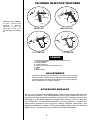
1
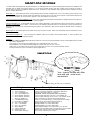
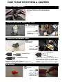
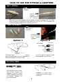
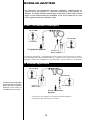
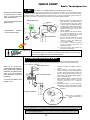
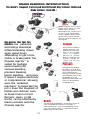
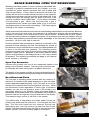
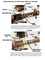
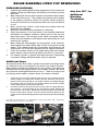
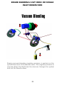
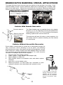
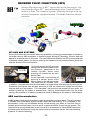
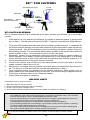
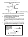
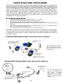
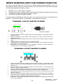
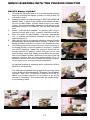
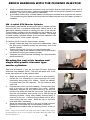
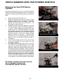
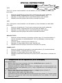
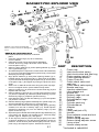
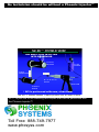
BENCH BLEEDING WITH THE PHOENIX INJECTOR 7. 8. When complete disconnect connector from tool output and let hose gravity bleed until a solid stream of fluid is seen. Position the bleeder hose into the primary reservoir to prevent draining. The m/c is now ready for installation. It should be noted many of these master cylinders are mounted at an angle on the vehicle. The procedures given earlier should be used on these vehicles once the master cylinder is installed. GM 4 outlet QTU Master Cylinder When dealing with the GM 4 outlet quick take up master cylinder that has the built in pressure differential switch there is an alternative bleeding method to raising the rear of the vehicle. These master cylinders can be identified by the presence of a hex plug located at the end of the master cylinder. The design of these master cylinders allows air to become trapped in the secondary portion of the master cylinder. To remove the air from this style master cylinder 1. Simply loosen the plug until fluid flow is established. With the plug loose Pressure bleed the secondary end of the master cylinder. 2. Tighten the plug as you end your last bleed stroke. The primary side of the master cylinder can be bled at the line without leveling the master cylinder. 3. Complete the bleed process following the recommended bleed procedure. Hex plug Bleeding the cast style tandem and single inlet plastic reservoir type master cylinders. Use this procedure if you do not have Phoenix Systems Universal Cap Adapter (UCA). The UCA will allow 90% of all screw cap reservoirs to be pressure bled. Begin by mounting the m/c in a vise in a level position. Install the m/c bleeding kit (not included) into both secondary and primary m/c outlets. Route the bleeder kit hoses back into the reservoir. Fill the reservoir with new fluid. 2. Prepare the tool for vacuum bleeding. Connect the input end of the tool to the secondary m/c outlet. Before beginning, depress the m/c piston about ½ so that the primary cup seals are past the vent ports. This will ensure that the low pressure area of the m/c is filled during the bleeding process. Using slow steady strokes apply a vacuum to the m/c. Continue this process until no air is seen exiting the m/c outlet. Keep an eye on the fluid level and refill if necessary. 3. Once the secondary portion of the m/c is bled route the bleeder kit hose back into the secondary reservoir. Repeat this procedure with the primary portion of the m/ c. Note - if m/c is mounted at an angle then follow appropriate steps for bleeding the rest of the system. See Brake Bleeding With The Phoenix Injector. Place in vise 1. 34 Install bleed kit and fill reservoir Depress piston & Vacuum bleed