1
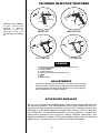
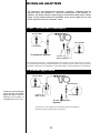
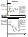
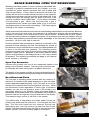
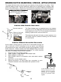
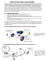
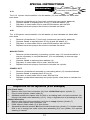
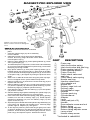
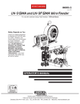
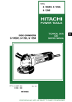
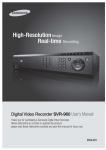
MAXIJECT-PRO EXPLODED VIEW
4a
1
2
5
6
4b
3
10
12
7
8
9
22
23
15
11
13
14
18
17
Adapter (19) must be turned 90 deg.
before it can be removed or damage will
occur.
27
28
21
24
25
19
REPAIR KIT INSTRUCTIONS
Tools required-slotted screw driver or coin and
pliers
1. Unscrew cylinder cage (15) as an assembly
from the handle.
2. Hold body of push rod (6) firmly without damaging
surface and using large flat blade screw driver,
unscrew piston cap (1).
3. Remove piston washers (4), piston spacing washer (5), check
valve (3) and spring (2).
4. To install new piston components, insert check valve assembly
(2,3) into the internal threaded end of push rod (6). Ensure that
the spring is pointing outward.
5. Align piston washers (4) with piston spacing washer (5) inbetween and fit over the piston cap (1). Place them in the palm
of your hand and carefully merge the push rod (6) onto the end
of the piston cap (1) and tighten by turning the push rod until it
stops.
6. With a coin or wide flat screw driver snug the piston cap tight.
Do not overtighten as the piston washers may distort.
7. Remove nozzle nut (12) and remove nozzle seal ring (9) and
replace with new seal.
8. Remove delivery cage lock nut (13) and remove delivery cage
(14) from the cylinder (18). Remove cylinder seal ring (17) from
the delivery cage(14). Replace cylinder seal ring.
9. Insert delivery cage (14) with new seal ring (17) into the cylinder
(18) at the 2.5 ml end.
10. Reinsert delivery cage cylinder assembly into cylinder cage (15)
and reinstall delivery cage lock nut (13) finger tight.
11. Insert new outlet check valve and spring (7&8), spring pointing
outward, into the end of delivery cage (14). Install injection
attachment assembly (10) onto the delivery cage (14) and
tighten nozzle nut (12)
12. Squeeze injector handle and install cylinder cage assembly (15)
over piston into handle until threads meet. Carefully align
cylinder cage an adapter (19) and tighten.
13. To test injector pressure, place index finger tightly over outlet
of injection attachment (10) and squeeze handle to check for
pressure. To test vacuum, place thumb tightly over inlet, rear of
push rod (6) and squeeze injector. Should feel vacuum.
43
20
26
PART
DESCRIPTION
1.
2.*
3.*
4.*
5.
6.
7.*
Piston cap
Inlet check valve spring
Inlet check valve and seal ring
Piston washer (set of 2)
Piston spacing washer
Piston Push rod
Outlet check valve and
seal ring
Outlet check valve spring
Nozzle seal ring
Injection attachment
Luer adapter nut
Nozzle nut
Delivery cage lock nut
Delivery cage
Cylinder/barrel cage
Deleted
Cylinder seal ring
Cylinder/barrel
Adapter
Lever
Lever pad (set of 2)
Handle
Dose adjuster screw and nut
Return spring
Return spring adjuster
Return spring adjuster screw
Lever screw
Handle clamp screw
8.*
9.*
10.
11.
12.
13.
14.
15.
16.
17.*
18.*
19.
20.
21.*
22.
23.
24.*
25.
26.
27.
28.
* Included in rebuild kit