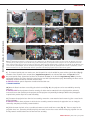
1
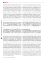
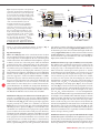
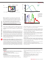
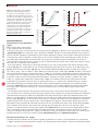
protocol © 2012 Nature America, Inc. All rights reserved. a b Sample plane Camera C-mount coupler Inverted Petri dish ///ALLIED Figure 1 | Optical configuration of the system and components. (a) Final optical configuration for the system. The epifluorescence optics are replaced by an accessory tube lens (infinity corrected) or relay lens pair (160 mm) and a modified 3-LCD projector. (b) Optical configuration of the projector in the original unmodified state. (c) Optical configuration of the constructed illumination system for an infinity-corrected microscope. (d) Optical configuration of the constructed illumination system for a 160-mm microscope. ATL, accessory tube lens; BFLRLP, back focal length of the RPL; FFLRLP, front focal length of the RLP; FLATL, focal length of the ATL; PDL, projector diverging lens; PI, projected image (M > 1); PPI, projector primary image; PZL, projector zoom lens; OL160mm, objective lens (160 mm); OLIC, objective lens (infinity corrected); RLP, relay lens pair; IP160 mm,160 mm back image plane; SLM, spatial light modulator; SP, sample plane (M < 1). Adapted from reference 12. PI PZL Motorized XY stage SLM PPI Primary projector Image 3-LCD PROJECTOR x4 objective PDL 662 nm dichroic c SLM Accessory tube lens (infinity corrected) or relay lens pair (160 mm) PZL ATL PPI d OLIC SLM PZL RLP PPI OL160 mm IP160 mm SP FLATL inputs or closed-loop automated analysis of images (Fig. 2; e.g., targeting neurons and muscles in C. elegans12,13). Experimental design Choice of 3-LCD projector. A few considerations must be taken into account when selecting a 3-LCD projector. The main specifications of importance are the brightness, the size of the LCD panels and the contrast ratio. The combination of the brightness (reported in lumens) and the size of the LCD panels define the maximum possible intensity of the demagnified image at the sample plane. Because the etendue of an optical system cannot decrease, a projector with the same reported brightness yet smaller LCD panels will yield greater intensity at the sample plane. Therefore, a projector that maximizes the brightness (minimum suggested is 2,000 ANSI lumens) with the smallest panels should be chosen (maximum panel size suggested is 1 inch). The Hitachi CP-X605 is a 4,000– ANSI lumen projector with 0.79-inch LCD panels and is used in this protocol. Also important is the contrast ratio. Both DLP- and LCD-based systems have no true zero intensity: even when the DLP or LCDs are in the off state, there is a finite amount of background illumination. To minimize the background illumination (thus preventing unwanted excitation of the optogenetic reagents), a high-contrast-ratio projector (at least 500:1) should be selected. The Hitachi CP-X605 has a stated contrast ratio of 1,000:1. Modification of the projector and insertion of custom optics. The protocol to reconfigure the 3-LCD projector (Hitachi CP-X605) begins by removing the diverging projection lens and inserting custom filters internally (Fig. 3a). The action spectra of the optogenetic reagents previously used12, ChR2 (ref. 1) and MAC3, are shown in Figure 3b. The spectrum of each color of the unmodified Hitachi CP-X605 projector is quite broad (Fig. 3c)12 and would thus cause considerable cross-activation between optogenetic reagents. Similar spectra would be observed for other 3-LCD projectors. Therefore, to limit the spectral width of the excitation, custom filters are added inside the projector; the filters in this protocol are chosen to maximize optogenetic activation and minimize cross-activation. To fit in the projector, the new filters must either be custom sized by a filter company (e.g., Semrock or Chroma) or cut from a larger filter by a professional glass cutter. The specifications, dimensions SP FFLRLP BFLRLP 160 mm and method of cutting of the filters used in this protocol (for the Hitachi CP-X605) are found in Supplementary Table 1. Filter sizes for alternative projectors can be determined through careful mea suring (Supplementary Note 2) of the locations for filter insertion in PROCEDURE Step 9. The postmodification spectrum (Fig. 3c) has much narrower spectral widths for each color, allowing for highly defined multicolor excitation. Modification of microscope optics for infinity-corrected systems. The epifluorescence optical train of a microscope cannot properly relay the projector image to the sample plane as its lenses are not of the proper style or focal length and thus must be removed to make room for the custom optics. In this protocol, we describe the modifications for both the infinity-corrected microscope and for the 160-mm fixed-tube-length microscopes. In an infinitycorrected microscope, the objective lens and tube lens combine to form a two-lens system, and when imaging the amount of magnification is determined by the ratio of the focal lengths of two lenses (M = TLfl/OLfl > 1). To transfer the projector’s primary image (PPI, Fig. 1c) to the sample plane (Fig. 1c), an accessory tube lens (ATL, Fig. 1c) must be inserted in the optical path between the projector and the objective. The magnification in this direction is again determined by the ratio of the focal lengths of two lenses (M = FLOL/FLTL), which will yield M < 1 or cause demagnification. Tube lenses from different microscope manufacturers have different focal lengths (Leica, 200 mm; Nikon, 200 mm; Olympus, 180 mm; and Zeiss 165 mm). The ATL to be inserted should be chosen to best match the focal length of the tube lens of the microscope manufacturer; in this way, the power of the objective closely matches the amount of demagnification. The distance between the ATL and the PPI should be equal to the focal length of the ATL (Fig. 1c). The distance between the ATL/projector combination and the objective lens is not as critical; however, it is generally recommended that this distance be kept as short as possible. Modification of microscope optics for 160-mm fixed-tube-length systems. Although the 160-mm fixed-tube-length microscopes are an older style, they are more than adequate for the purpose of constructing this multispectral illumination system and can often be found more inexpensively. In a 160-mm fixed-tube-length microscope, nature protocols | VOL.7 NO.2 | 2012 | 209