1
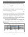
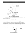
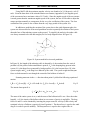
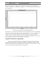
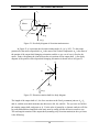
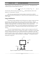
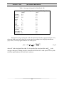
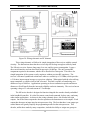
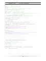
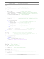
December 7, 2010
[SKY VISION: FINAL DESIGN]
.
Eq. 17
In order to obtain the angular momentum, the inertia tensor in the
determined. The inertia tensor of the output shaft and camera in the
frame must be
frame is the following:
Eq. 18
Since there are two planes of symmetry, all of the products of inertia drop out (
principal set of axes). The angular momentum,
, is
frame is
Eq. 19
To find the necessary motor torque , the moments must be summed and set equal to the time
derivative of the angular momentum. Point A is a valid location to sum moments since it is not
accelerating (no longer acceptable when azimuth rotation is considered).
Eq. 20
Eq. 21
It can be determined from Figures 21 and 22 that
. Setting the latter two relations equal
exposes the fact that
For the static situation (
, the moment balance
degenerates into
,
Eq. 22
which is the static holding torque required by the elevation rotation motor. The maximum
holding torque occurs at
, and is dependent on the mass of the shaft, length of the
shaft, and mass of the camera. The MATLAB code provided in Appendix G calculates the
holding torque across all values of .
Mechanical Imaging System Component Selection
Three possible mechanisms for accomplishing the elevation and azimuth rotation are
available: stepper motors, brushless DC (direct current) motors, and servomotors. Stepper
motors are available in different angular step rotations per pulse. As step size decreases, control
of the camera location increases in precision. Stepper motors seem to be heavier than
servomotors, but also less complex. The next option for camera rotation is brushless DC motors;
39