1
December 7, 2010
[SKY VISION: FINAL DESIGN]
HARDING UNIVERSITY
Sky Vision: Final Design
Philip Varney
Cristina Belew
Julianne Pettey
Peng Yang
12/7/2010
1
December 7, 2010
[SKY VISION: FINAL DESIGN]
Table of Contents
Requirements Specification……………………………………………………………………………… 4
Overview………………………………………………………………………………………….. 5
Problem Statement………………………………………………………………………………... 5
Requirements………………………………………………………………………………………6
Deliverables………………………………………………………………………………………..6
User Manual………………………………………………………………………………………..7
Test Plans ………………………………………………………………………………………….7
System Design……………………………………………………………………………………………...9
Background……………………………………………………………………………………….10
System Overview…………………………………………………………………………………11
Organization and Management…………………………………………………………………...13
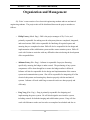
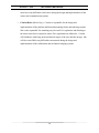
System Block Diagram…………………………………………………………………………...15
Functional Descriptions of Subsystems ………………………………………………………….16
Final Design………………………………………………………………………………………………19
Stabilization System Design…………………………………………..………………………….20
Mechanical Imaging Design……………………………………………………………………...37
Electrical Imaging Design………………………………………………………………………..45
Platform Design…………………………………………………………………………………..48
Tethering Design………………………………………………………………………………….59
Power System Design…………………………………………………………………………….61
Communication System Design………………………………………………………………….70
User Interface Design…………………………………………………………………………….82
Budget ……………………………………………………………………………………………………83
Budget Overview…………………………………………………………………………………84
Subsystem Budgets……………………………………………………………………………….85
Project Management……………………………………………………………………………………..88
Fall 2010 Gantt Chart…………………………………………………………………………….89
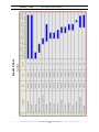
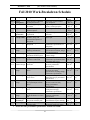
Fall 2010 Work-Breakdown Schedule……………………………………………………………90
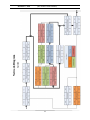
Fall 2010 Network Diagram ……………………………………………………………………..91
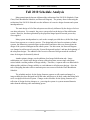
Fall 2010 Schedule Analysis……………………………………………………………………..92
Spring 2011 Gantt Chart………………………………………………………………………….93
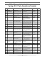
Spring 2011 Work-Breakdown Schedule ………………………………………………………..94
Spring 2011 Network Diagram…………………………………………………………………...96
References………………………………………………………………………………………………...97
2
December 7, 2010
[SKY VISION: FINAL DESIGN]
Appendices …………………………………………………………………………………………….…99
Appendix A: FAA Regulations………………………………………………………………….100
Appendix B: Propeller Justification MATLAB Code…………………………………………..105
Appendix C: Maximum Wind Force MATLAB Code …………………………………………107
Appendix D: APC 10 x 4.7 Propeller Data Sheet……………………………………………….109
Appendix E: Hacker A20 - 20L Motor Data Sheet……………………………………………...112
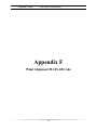
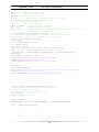
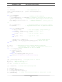
Appendix F: Wind Alignment MATLAB Code………………………………………………...115
Appendix F – 1: Wind Response MATLAB Code ……………………………………………..117
Appendix G: Elevation Rotation Motor Holding Torque MATLAB Code……………………..120
Appendix H: Hitec HS-81 Servomotor Data Sheet……………………………………………..122
Appendix I: Transmissibility MATLAB Code………………………………………………….124
Appendix J: Sorbothane Vibration Isolation Material…………………………………………..126
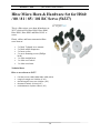
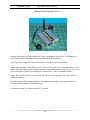
Appendix J – 1: Hitec HS-81 Attachment Kit…………………………………………………..129
Appendix K: Booster Vision GearCam…………………………………………………………131
Appendix L: Balloon Data Sheet………………………………………………………………..133
Appendix M: Microprocessor…………………………………………………………………...135
Appendix N: Microprocessor Power Demands…………………………………………………139
Appendix O: Schmart Board……………………………………………………………………141
Appendix P: Voltage Regulators………………………………………………………………..143
Appendix Q: Auxiliary to USB Connector ……………………………………………………..146
Appendix R: Remote controller system…………………………………………………………148
Appendix S: Transmitter………………………………………………………………………...151
Appendix T: Receiver…………………………………………………………………………...153
3
December 7, 2010
[SKY VISION: FINAL DESIGN]
Requirements
Specification
4
December 7, 2010
[SKY VISION: FINAL DESIGN]
Overview
The goal of Sky Vision is to design and construct a cost effective, mobile flight platform
with the capability to remotely capture video and transmit the data to a user on the ground
in real time. The need for aerial imaging spans a wide array of markets, such as search
and rescue, law enforcement, construction, the media, fire fighting, and general
recreation.
Aerial imaging greatly expands the capabilities of the aforementioned markets. It
reduces the manpower (and thus costs and risks) needed for many dynamic situations,
such as monitoring the scene of a crime or surveying the extent of a wildfire. In short,
aerial imaging extends the sensing capabilities of a market from a two dimensional field
into a third dimension: the sky.
Currently, this capability is far too often accomplished through the use of expensive
rotary and fixed wing aircraft. The costs of the prior options often far eclipse the
resources of many markets, thus necessitating a cost effective alternative. The goal of
Sky Vision is therefore to create an aerial imaging product which meets both the high
performance and low cost requirements of many under resourced markets.
Problem Statement
Obtaining aerial imaging of a dynamic situation can be both costly and complicated.
There is a need spanning a wide range of markets for an aerial device with the capability
of remotely capturing aerial images at a low cost. In order to fulfill the market
requirements, the device should have the capability to be easily transported to the area of
interest.
5
December 7, 2010
[SKY VISION: FINAL DESIGN]
Requirements
The power system should allow for a minimum of 1 hour flight time and also a
minimum of 30 minutes of live video, not necessarily continuous, from the camera
system.
The motion of the device and/or camera should allow for both 360 of azimuth
rotation and 90 of elevation rotation of the camera in order to provide a stabilized
image (Stabilized: no more than 25% displacement within a 0.5 s interval of a screen
centered, locked object).
The 360 degrees of azimuth rotation should be accomplished in a 5 minute time
interval.
The camera system will be able to lock on (via either user control or automation) to
some object on the ground and remain fixed on that object until the user acquires a
new target object.
The device will be able to rise to a maximum height of no less than 36.6 meters (120
ft) in order to ensure customer‟s needs for aerial imaging are met.
The device should obey all pertinent FAA regulations (FAA regulation 101, subparts
A and B; see Appendix A).
The communication range of the device should be at least 50 meters.
The device should be able to withstand maximum winds of no less than 5 m/s.
The device should be no more than 0.43 m3 (15 cu. ft) and the dimensions should not
exceed 1.30 m x 1.04 m x 0.56 m. when deflated, in order to fit into the trunk of a
standard mid-sized car (based on stats for 2011 Honda Accord).
The device development costs should not exceed 1,000 USD.
Deliverables
Parts manual and corresponding budget
User manual
Detailed schematic and final report on device capabilities
System capability specifications
6
December 7, 2010
Aerial surveillance device
User interface
Non-supplied parts:
-
[SKY VISION: FINAL DESIGN]
Helium gas will be provided for testing purposes, but the customer will be
responsible for obtaining helium gas for later flight.
-
A user provided laptop computer will be necessary to view the live video feed.
User Manual
1. Remove device from storage and ensure the tether system is correctly connected to
the blimp.
2. Connect the power system to the tethering system and power on the device and user
interface.
3. Add necessary helium gas to the blimp until fully inflated.
- User must supply helium gas.
4. Slowly extend tethering line to allow blimp to rise to desired elevation.
5. Obtain desired imaging using camera and blimp positioning systems, done via the
user interface.
6. Slowly reel in tethering line until blimp has reached ground level.
- Maintenance: ensure blimp is intact with no leaks.
- Maintenance: when reeling in tethering line, check visually for damaged areas.
7. Remove gas from blimp and disconnect tether system from power system.
8. Place system in storage.
Test Plans
The power system will be connected to the imaging and stabilization systems and
tested at a short vertical height for 1 hour to verify power needs (this includes 30 min.
of video feed testing). The time duration will be tested using a commercial stopwatch
device.
To test image stability, 1 minute of continuous video will be recorded with the
camera locked onto a single object for the entire 1 minute duration. The 1 minute
video clip will then be broken into 0.5 second intervals and it will be verified that the
locked object did not drift more than 25% of the screen size during each interval.
To test 360 of azimuth rotation and 90 of elevation rotation, the device will be
flown indoors and the 360 will be verified by the ability of the camera to capture a
full panoramic picture (or protractor in case of camera failure), and the 90 elevation
7
December 7, 2010
[SKY VISION: FINAL DESIGN]
rotation measured using a protractor. The 360 azimuth rotation will be timed using a
commercial stopwatch device to verify the 5 minute rotation duration.
The device will be flown outdoors to verify camera locking ability. An object on the
ground will be preselected and the camera should keep the object in the video feed for
a duration of 5 minutes.
To verify the maximum flight height of no less than 36.6 meters, the device will be
flown and the amount of tethering cable measured using a measuring tape and related
appropriately (accounting for cable droop due to the weight of the cable) to the height
of the device. This will cause the measured tether cable to be greater than the
maximum flight height. The appropriate relation for cable droop will be provided
following appropriate testing and analysis.
The device will be flown in 5 m/s or greater winds to test flight stability. To verify
flight stability, the positioning and camera systems should still be capable of locking
onto an object on the ground and remaining locked onto that object for a duration of 5
minutes with 5 m/s wind present.
To allow for wind variability, a 2 week testing period will be selected and the device
tested at different states of wind speed. The extended testing time allows for
adjustments to be made to the device, as well as to account for random wind speed
variation.
The communication system will be tested by flying the device at its maximum height
of 36.6 meters and ensuring communication is not lost.
The dimensions of the deflated device will be measured to ensure that both the
volume and dimensions of the device do not exceed the specified dimension/volume
requirements. The dimensions will be measured using a standard measuring tape.
8
December 7, 2010
[SKY VISION: FINAL DESIGN]
System Design
9
December 7, 2010
[SKY VISION: FINAL DESIGN]
Background
Sky Vision will meet the needs provided in the Requirements Specification by being far
less expensive than the current methods used to obtain aerial images. Sky Vision aerial imaging
will be an alternative to renting or purchasing expensive equipment outright. Using Sky Vision
will be much more convenient for the customer, since the system can be easily transported to the
required location. Sky Vision will use helium to fly a small video camera to the altitude
necessary to obtain the desired live video feed. The camera will transmit the live video feed to a
user interface on the ground. The system will be stabilized by a lightweight stabilization system.
The stabilization system will be remote-controlled from the user interface on the ground.
10
December 7, 2010
[SKY VISION: FINAL DESIGN]
System Overview
The goal of Sky Vision is to provide a cost effective method of aerial surveillance for
dynamic situations. Sky Vision will consist of a lighter-than-air aerial platform with stable live
video imaging and a stabilization system. Since most markets with a need for aerial surveillance
also demand high adaptability, Sky Vision will measure no more than 1.30 m x 1.04 m x 0.56 m.
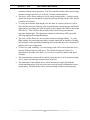
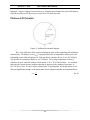
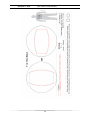
To satisfy the needs of the customer, Sky Vision will be capable of providing both 360 of
azimuth rotation and 90 of elevation rotation of the imaging system. Azimuth rotation is
defined as a horizontal rotation in a fixed reference plane; in this case the fixed reference plane is
the plane perpendicular to an axis fixed to the device which passes vertically through the center
of gravity of the device when it is in a vertical orientation (see Figure 1). Ninety degrees of
elevation rotation is defined as a rotation from the previously mentioned fixed plane to a position
perpendicular to the plane, directed downward. The stabilization system will provide
stabilization against wind force. The elevation rotation and azimuth rotation will be provided
independent of the stabilization system.
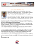
Figure 1: Azimuth and elevation rotation
Sky Vision will be operated by the customer using a portable user interface device. The
user interface will provide three important functions: (1) control of the imaging system and
simultaneous viewing of the live video feed, (2) control of the stabilization system, and (3)
control of deflation of the balloon.
To use Sky Vision, the user will remove the system from storage and ensure the aerial
platform is correctly secured to the tethering system (prior to inflation with helium gas). The
11
December 7, 2010
[SKY VISION: FINAL DESIGN]
platform will then be connected to the power source and both the platform and user interface will
be powered on. The user will then add the required volume of helium gas to inflate the platform
(note that the customer will provide any required helium gas, except for that required by system
development and testing). The tethering system will then be slowly released, allowing Sky
Vision to slowly rise to the desired altitude. Once Sky Vision has reached the desired altitude, the
user may then utilize the imaging and stabilization systems to obtain the desired field of view for
the live video feed. Once imaging is complete, the user will slowly reel in the device, while
visually inspecting the tether for damage. Once the platform has reached ground level, the user
will inspect it to ensure the integrity of the platform has not been compromised. The valve
system will then be used to remove the helium gas from the platform. Following helium gas
removal, the system will be powered off and returned to storage.
Platform Selection
Three options were considered concerning the type of platform the aerial imaging system
would be mounted on. The three choices were a fixed wing aircraft, a fully mobile and untethered blimp, or a tethered spherical balloon with limited propulsion/mobility. A downside of
the fixed wing aircraft is that it would have been too difficult to design in the allotted time; also,
it would not have provided the necessary level of imaging stability. One disadvantage of the
spherical balloon is that it would not have given the freedom for the user to move to the desired
location needed for imaging. The first choice considered was the blimp; this option would have
provided an easier method for moving the blimp to the desired imaging location dictated by the
user. However, the problem which arose when looking at blimp-shaped balloons was the price:
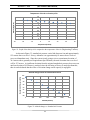
most small blimp-shaped balloons were between $500 and $1000. The decision matrix utilized
to decide on a platform is shown in Table 1.
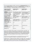
Table 1: Decision matrix between balloon, airplane and blimp.
Stability
Cost
User Control
Complexity
Total
Weight
0.3
0.3
0.2
0.2
1.0
Balloon
3
3
3
4
3.2
12
Airplane
2
1
1
1
1.3
Blimp
2
1
4
2
2.1
December 7, 2010
[SKY VISION: FINAL DESIGN]
Organization and Management
Sky Vision’s team consists of two electrical engineering students and two mechanical
engineering students. The project tasks will be distributed between the project members as
follows:
o Philip Varney (Mech. Eng.) - Phil is the project manager of Sky Vision, and
primarily responsible for making sure the subsystem plans are completed, integrated,
and tested on time. Phil is also responsible for finalizing all required reports and
ensuring they are completed on time. Phil will also be responsible for the design and
implementation of the stabilization system and the camera rotation system. Phil will
work with Cristina to assist her with any difficulties that arise during the development
of her responsibilities.
o Julianne Pettey (Elec. Eng.) - Julianne is responsible for project financing;
specifically, ensuring the budget is under control. The purchasing of any system
components will be done through her to ensure the budget outline is followed.
Julianne will also be responsible for the design and implementation of the camera
system and communication system. She will be responsible for integrating all of the
electrical subsystems and ensuring they function properly with the mechanical
systems. Julianne will work with Peng to ensure his tasks are done properly and
efficiently.
o Peng Yeng (Elec. Eng.) - Peng is primarily responsible for designing and
implementing the power system. He will also design the user interface system,
including controls for both the imaging and stabilization systems. Peng will also
work with Julianne to make sure her tasks are completed on schedule and also to
13
December 7, 2010
[SKY VISION: FINAL DESIGN]
assist her in any difficulties which arise during the design and implementation of the
camera and communication systems.
o Cristina Belew (Mech. Eng.) - Cristina is responsible for the design and
implementation of the platform (balloon and mounting frame) and tethering systems.
She is also responsible for examining any relevant FAA regulations and dictating to
the entire team what is required to ensure FAA regulations are adhered to. Cristina
will collaborate with Peng on the mechanical aspect of the user interface design. She
will also assist Phil in any difficulties encountered during the design and
implementation of the stabilization and mechanical imaging systems.
14
[SKY VISION: FINAL DESIGN]
System Block
Diagram
December 7, 2010
15
December 7, 2010
[SKY VISION: FINAL DESIGN]
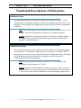
Functional Descriptions of Subsystems
Stabilization System:
The stabilization system will consist of two propellers mounted on a shaft. A wind
alignment plate will align the propellers in a direction parallel to the wind velocity. The
propellers will be capable of providing stability against wind-induced lateral translation
of balloon.
Input: User control signal from user interface via motor control circuit (see „User
Interface‟ functional description for specifics on user input mechanism)
Output: Stabilization of balloon (maximum of 10 N thrust to stabilize against
wind speed range specified in Requirements Specification) and alignment of
propellers with wind direction.
Communication System:
The communication system will remotely control the stabilization system and imaging
rotation motors. It will transmit a signal from the user interface via a DSPIC30F6015
microprocessor to a motor control circuit that determines stabilization thrust. The signal
will be transmitted wirelessly and will be in compliance with all relevant FCC
communication standards and regulations.
Input: Signal generated from remote-control device on user interface and
transmitted at radio frequency at 2.4 GHz.
Output: Signal to a DSPIC30F6015 microprocessor, motor control circuit and
camera control circuit; which sends power to the stabilization units and camera; 5
V and 25 mA control signal to stabilization system and imaging rotation motors
16
December 7, 2010
[SKY VISION: FINAL DESIGN]
Power System:
The power system provides the necessary power for the stabilization system, user
interface, and communication system (power for camera is described under Imaging
System). The power system consists of a system of four lithium polymer batteries (2500
mAh, 11.1 V), two voltage regulators, and an 11.1 V 850 mAh secondary battery. The
power system will provide power to the system for a minimum of one hour, including 30
minutes of power to the imaging system and a variable amount of power to the
stabilization system as dictated by imaging position needs and wind speed.
Input: Power of batteries (11.1 V, 2500 mAh and 850 mAh).
Output: Power to systems ( Maximum of 120 W to each Hacker A20-20L
propeller motor, 5 V and 45 mA to microprocessor, receiver, and decoder, and 6.0
V and 0.5 A to imaging rotation servomotors).
Tethering System:
The tethering system includes both a reel device to allow for ascending and descending of
the balloon and also a tethering cable which is capable of securing the balloon. The
device should be deployable to and from its maximum height of 36.6 meters within 10
minutes. In order to ensure that the height of the device does not exceed 36.6 meters, the
tethering system will only be capable of letting out 36.6 meters of cable. The tethering
material will have a factor of safety against rupture of at least 2.0
Inputs: 10 N mechanical reeling force.
Outputs: Change in device elevation, from 0 meters to the maximum height of
36.6 meters.
17
December 7, 2010
[SKY VISION: FINAL DESIGN]
Imaging System:
The imaging system will consist of a small camera mounted onto the balloon. The
camera will be capable of 90 elevation rotation and 360 of azimuth rotation,
accomplished via independently controlled motors. The live video feed will be
transmitted to the ground and made viewable on the user interface. The camera will be
adjusted to focus at a distance sufficient to accommodate the maximum flight height.
Inputs: Control signal from user interface. 9 volt power supply from battery to
camera. 6.0 V and 500 mA to servomotors.
Outputs: Live video feed displayed on the user interface. 90 elevation rotation
and 360 of azimuth rotation at 9.52 rad/s and 0.3 N m.
Platform:
The platform consists of both a helium filled balloon and the required mounting
infrastructure. The helium filled balloon will provide enough lift to bring the system to
the desired elevation, and the required mounting infrastructure will support the imaging
and stabilization systems.
Input: 5
of helium gas required to lift system (helium gas can lift
approximately 1.1 kg/m3 at 20 C and 1 atm .
Output: Desired elevation of the system.
User Interface:
The user interface consists of the user provided laptop used to view the live video feed.
The live video feed will be viewable on the user interface, which will be a user-supplied
laptop computer.
Input: AUX signal from transmitter.
Output: Viewing of live video feed on laptop computer via USB
18
December 7, 2010
[SKY VISION: FINAL DESIGN]
Final Design
19
December 7, 2010
[SKY VISION: FINAL DESIGN]
Stabilization System Design
Overview
The goal of the stabilization system is to provide platform stabilization in varying wind
conditions, as dictated by the Requirements Specification. The stabilization system consists of
two propellers driven by high rpm electric brushless motors mounted on the same rigid shaft
beneath the balloon. In order to effectively stabilize against wind, the propellers must provide a
thrust force equal but opposite to the drag force on the balloon caused by the wind. To fully
stabilize against the wind, the thrust force generated by the propellers must therefore be opposite
in direction of the drag induced by the wind. In order to align the thrust force opposite to the
drag force, the propeller assemblies must be capable of 360 horizontal rotation. To accomplish
the necessary rotation, a light-weight alignment plate will be attached perpendicular to the shaft
supporting the motors. The drag force on the alignment plate will cause a moment which will
rotate the propellers to the position necessary to stabilize against the wind.
Stabilization System Components
The main components of the stabilization system are the following:
1.
2.
3.
4.
5.
Propellers
Electric motors driving the propellers
Shaft/bracket connecting the propeller/motor assemblies to the same shaft
High frequency passive (not powered) vibration damping/isolation bolts/brackets
Wind alignment plate
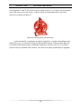
Stabilization System Justification
In order to justify the use of a dedicated stabilization system, a simulation was created
and performed which analyzed the dynamics of the system both with the stabilization system and
without it. The simulation used a free-body analysis of the balloon to calculate the tension in the
tethering cable and the angular deflection of the balloon about an axis parallel to the ground.
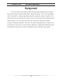
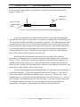
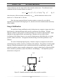
The first step in the simulation was to develop a dynamic model of the system. The
model developed is provided below in Figure 2.
20
[SKY VISION: FINAL DESIGN]
December 7, 2010
Figure 2: Dynamic model of system
In Figure 2, the center of mass of the simplified system is shown to be at the center of the
spherical balloon and is represented by the designation G. The weight of the system is
designated
, the tension in the tethering capable is , the buoyant force exerted on the
balloon is , the drag force is , and the thrust force generated by the propellers is . The
tension in the cable is along the direction of the cable, which is inclined an angle . The buoyant
force acts through the centroid of the balloon, which in this simplified case also corresponds to
the center of gravity, . The drag force
acts through the centroid, and the line of action of the
thrust force is assumed to act through the center of gravity (this assumption is valid since the
center of gravity can always be shifted to a desired location by adding an appropriate amount of
mass at the required distance).
From Figure 2, the differential arc length
the coordinate axes by the following relation:
can be related to the differential lengths of
.
To determine the deflection angle of the cable, it is first necessary to sum forces in the
directions. The sum of the forces in the direction is
Eq. 1
and
Eq. 2
and the sum of the forces in the
direction is
.
21
Eq. 3
[SKY VISION: FINAL DESIGN]
December 7, 2010
The above expressions can be simplified by realizing that
and
. Setting
and inserting the latter expressions and also Eq. 1 into the force balance equations yields
the following simplified results for the force balance equations:
Eq. 4
.
Eq. 5
Once , , , and
are quantified, the above nonlinear expressions can be solved in
MATLAB using the code provided in Appendix B.
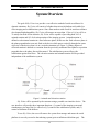
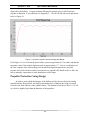
The goal of the simulation is to check the response of the tilt and the cable tension to
variations in thrust force and to ensure that the addition of a stabilization system is justified by
significant reductions in both tilt and cable tension. Large values of tilt in the cable cause large
angular deflections of the balloon, which contribute to decreased image stability. Large tension
values decrease the total weight the balloon can lift, as the buoyant force has to then counter both
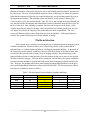
the system weight and the tension. The values generated by the MATLAB code for tilt versus
thrust force and tension versus thrust force are provided in Figures 3 and 4, respectively.
Tilt vs. Thrust Force
60
Tilt (degrees)
50
40
30
20
10
0
0
2
4
6
8
Thrust Force (N)
Figure 3: Tilt vs. Thrust Force
22
10
12
14
[SKY VISION: FINAL DESIGN]
December 7, 2010
Tension vs. Thrust Force
18
16
14
Tension (N)
12
10
8
6
4
2
0
0
2
4
6
8
10
12
14
Thrust Force (N)
Figure 4: Tension vs. Thrust Force
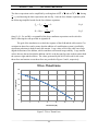
Figures 3 and 4 were created by holding the wind force constant at 12 N (worst case
scenario corresponding to wind value exceeding the maximum value specified), the system
weight constant at 49 N, and the buoyant force constant at 59 N and varying the thrust force from
0 to 12 N. From Figures 3 and 4, it is clear that as thrust force is increased, the tilt decreased
exponentially and the tension in the cable decreases towards a constant value equal to the
difference between the system weight and buoyant force. It is evident from the above simulation
that the addition of thrust force decreases the cable tilt from a large value to a much smaller
value, and also decreases the tension in the cable to a lesser value, thus justifying the use of a
dedicated stabilization system.
Wind Force Calculation
In order to determine the necessary thrust force to stabilize against wind, the drag force
caused by the wind must be quantified. The Requirements Specification document dictates that
the system must be capable of providing a stabilized image in wind speeds up to 5 m/s. Drag
force is caused by fluid flow external to the body over which the fluid is flowing. Assuming that
23
[SKY VISION: FINAL DESIGN]
December 7, 2010
the flow over the body can be modeled as incompressible (accurate assumption since the free
stream fluid velocity is very low), the drag force can be quantified by the following expression:
.
Eq. 6
The coefficient of drag is
the density of the free stream is , the velocity of the free stream is
, and the projected frontal area of the body is
The projected frontal area of a spherical body
is
, where the diameter of the body is . The drag coefficient for a spherical body
depends on the Reynolds number of the fluid flow, and can only be determined empirically. The
Reynolds number for external flow over a spherical body is
,
Eq. 7
where is the kinematic viscosity of the fluid flow. The critical Reynolds number for the flow is
approximately
(Cengel and Cimbala 2006). At the critical Reynolds number, the flow
over the sphere sharply transitions from laminar flow to turbulent flow, causing a commensurate
reduction in drag force. Corresponding to the change in the flow regime of the fluid is a
proportionate change in the drag coefficient across the sphere; in the laminar regime,
,
and in the turbulent regime
(Cengel and Cimbala 2006). For the discussion to be
useful, it is necessary to determine the sensitivity of the drag force to changes in air temperature,
as kinematic viscosity varies greatly with temperature variation.
An analytical expression for the change in kinematic viscosity with temperature change
was obtained by plotting empirical data points in Microsoft Excel and then performing a
regression analysis on the data points. The data for kinematic viscosity of air was obtained from
the properties charts provided by Cengel and Cimbala, 2006. The results of the regression are
shown below in Figure 5.
Kinematic Viscosity (m^2/s)
Kinematic Viscosity v. Temperature
-30
2.000E-05
1.500E-05
y = 8.79302E-08x + 1.34039E-05
R² = 9.99640E-01
1.000E-05
5.000E-06
0.000E+00
-20
-10
0
10
20
Air Temperature (deg. C)
Figure 5: Kinematic Viscosity vs. Temperature
24
30
40
[SKY VISION: FINAL DESIGN]
December 7, 2010
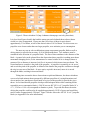
It is evident from Figure 5 that kinematic viscosity of air at a pressure of 1 atm varies
linearly with temperature changes. The linear regression equation obtained in Excel is shown in
the upper right corner of Figure 5. The regression analysis was very accurate, as the squared
correlation coefficient ( ) was very close to 1. Entering the regression equation shown in
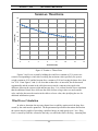
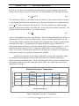
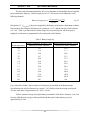
Figure 5 into the MATLAB code in Appendix C yielded the data for maximum wind force vs.
temperature provided in Table 2. The wind velocity values in Table 2 were selected based upon
wind values inducing the maximum drag on the system; an explanation is provided in the
following pages.
Table 2: Maximum wind force
Air Temperature (°C)
-20
-15
-10
-5
0
5
10
15
20
25
30
Max Wind Force (N)
5.09
5.49
5.91
6.34
6.79
7.20
7.68
8.17
8.68
9.21
9.68
Velocity (m/s)
2.32
2.41
2.50
2.59
2.68
2.76
2.85
2.94
3.03
3.12
3.20
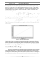
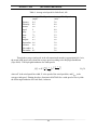
A sample wind force vs. wind velocity plot is shown below in Figure 6 for a temperature of 30
C and a 1 m diameter balloon.
Abrupt transition
due to change in
fluid flow from
laminar to
turbulent
Figure 6: Wind Force vs. Wind Velocity
25
December 7, 2010
[SKY VISION: FINAL DESIGN]
It is interesting to note that the critical Reynolds number is reached at approximately 3
m/s. This causes the drag coefficient to drop significantly, causing the maximum drag force to
occur at a velocity between 0 and 5 m/s. For this reason, Table 2 also contains data showing at
what velocity the maximum wind force occurs at. Evident from Table 2 is the observation that
drag force increases with air temperature. From Table 2, it was determined that the stabilization
units needed to produce a combined value of at least 10 N to successfully stabilize against wind
speeds from 0 – 5 m/s.
Note, however, that the transition from laminar to turbulent flow is not as abrupt a
phenomenon as Figure 6 portrays. In order to approximate the drag over a wide range of wind
velocities, the drag coefficient had to be approximated as being either laminar or turbulent, with
no intermediary values. In reality, Figure 6 is a smoother curve, with a lower maximum peak.
The approximation used above is therefore a very liberal approximation of wind drag.
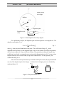
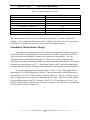
Stabilization Unit Selection
The next step in the stabilization system design was to select appropriate stabilization
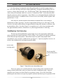
units to generate the required minimum of 10 N of thrust. Two options were initially considered:
ducted fans and open-air propellers. Ducted fans consist of a motor and propeller blade
surrounded by a low clearance cylindrical duct (see Figure 7). Open-air propellers, however, do
not have the cylindrical duct encasing the propeller blade.
Exterior duct
encasing motor
Interior propeller
(removed from duct)
Figure 7: Ducted fan (www.ductedfans.com)
These two options were considered because a large market (radio-controlled aircraft)
already existed which relied on the use of those two forms of stabilization units. Open-air
propellers were chosen over ducted fans for two primary reasons. First of all, ducted fans
producing the same thrust as an open-air propeller consumed much more power (upwards of 900
26
December 7, 2010
[SKY VISION: FINAL DESIGN]
W for the Fury EDF ducted fan on www.ductedfans.com). Second, ducted fans were generally
much more expensive and also heavier than open-air propellers producing the same thrust.
Ducted fans are used in the remote controlled aircraft market because they are capable of
producing values of thrust which could only be obtained otherwise by using very large
conventional propellers.
Predicting the thrust generated by an open-air propeller is a very complex problem. The
thrust force generated by the propeller is due to a pressure difference between the inlet and outlet
surfaces of the propeller. The pressure difference is due to some very complicated effects. The
pressure change is essentially generated because the propeller blade is a rotating wing with a
varying angle of attack and changing airfoil shape. Using Bernoulli‟s Law in combination with
the fact that force is equal to change in pressure times area yields the following result for a
rotating blade modeled as a thin disk:
.
Eq. 8
where
and were defined previously. The complication arises in that neither the exit
velocity nor the inlet velocity are known. The only other known method for analytically
determining the thrust force generated by a certain propeller is to use a finite element fluid
dynamics simulation based upon advanced airfoil theory. However, this analysis has been
performed by radio-control enthusiasts with knowledge of aerospace engineering and placed
online in the form of „thrust calculators‟. In order to validate the thrust calculators, two different
thrust calculators were used and the same numbers were input into each calculator. The results
were compared and found to be reasonably close in magnitude; they are presented in Figures 8
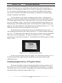
and 9 below. The results obtained from the online calculators seem to be reasonable, considering
the large pitch and diameter of the blades.
Figure 8: Thrust calculator #1 (http://www.gobrushless.com/testing/thrust_calculator)
27
December 7, 2010
[SKY VISION: FINAL DESIGN]
Figure 9: Thrust calculator #2 (http://adamone.rchomepage.com/calc_thrust.htm)
It is clear from Figures 8 and 9 that both the motor rpm and calculated thrust values (shown
circled) are close in magnitude. Please note that 18 oz-force of thrust is equivalent to
approximately 5 N of thrust, or half of the desired value of 10 N of thrust. For this reason, two
propellers were chosen rather than one larger propeller, as to minimize power consumption.
The next step was to select stabilization system components (propeller blade as well as
driving motor) to provide the necessary 10 N of stabilization thrust. Two attributes must be
considered in the selection of a propeller blade. The first of these attributes is the diameter of the
blade. A general rule can be gleaned from the observation that a propeller is nothing more than a
momentum changing device; as the momentum of a control volume of air is changed, thrust is
generated. So as diameter is increased, air flow is increased, which in turn increases thrust. The
second attribute to consider is the pitch of the propeller. A propeller is essentially an „air-screw‟,
and as such the pitch of the propeller is defined as the distance the propeller would move through
the air given one turn of the blade. So once again, as pitch is increased, more air is moved
through the blade, resulting in increased thrust.
Taking into account the above observations on pitch and diameter, the thrust calculators
were used to both estimate thrust generated by different propellers of varying dimensions and
also to analyze how much power would need to be given to the propeller to provide the given
thrust. It was found that the propeller which provided adequate thrust while remaining within
reasonable power consumption limits (< 200 W) was an APC SF 10 x 4.7 propeller blade (10‟ x
4.7‟ ( 25.4 cm x 11.94 cm) corresponds to diameter x pitch). To provide the thrust, the motor
driving the propeller would need to be supplied approximately 130 W of power and would also
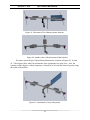
need to rotate at approximately 5500 rpm. Figure 10 below shows the APC SF 10 x 4.7 propeller
blade (see Appendix D for more information).
28
December 7, 2010
[SKY VISION: FINAL DESIGN]
Figure 10: APC SF 10 x 4.7 propeller blade
The next step was to select an appropriate motor to drive the propeller blade at the
necessary angular speed. In order to achieve high values of rpm and stay within reasonable
power supply limits, a brushless dc motor was chosen instead of a brushed motor, even though
the brushed motors often have substantially lower costs. An important factor to consider in
selecting the motor was a KV value high enough to allow the high rotation rates. The KV value
of an electric motor is a measure of how many rpm the motor can rotate per volt supplied.
Another important factor influencing motor selection was the weight of the motor. Since the
balloon can only lift a specified weight, it is crucial that the weights of all the components be
minimized. The last factor influencing motor selection was power demands. In order to produce
at least 5 N of thrust per propeller/motor assembly, each motor must be capable of receiving at
least 130 W of power.
The motor selected to meet the above criteria was a Hacker A20-20L Brushless outrunner motor. The mass of the motor is 55 g (1.94 oz), and the motor is capable of receiving 200
W of power at 11.1 V. The KV value of the motor is 1022 rpm/V; at 11.1 V the motor should
therefore be more than capable of rotating at 5500 rpm. The motor can sustain a constant current
of 6 – 15 A, with a maximum burst current of 19 A. It is interesting to note that the
manufacturer of the motor recommends the same propeller blade as was selected earlier in order
to prevent motor overload. The Hacker A20-20L brushless motor is shown below in Figure 11
(see Appendix E for more information and technical specifications).
Figure 11: Hacker A20-20L brushless motor
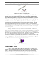
Wind Alignment Design
In order to stabilize against wind, the thrust force generated by the propellers must be
equal and opposite when compared to the drag force caused by the wind. Since the drag force
caused by the wind is in the same direction as the wind velocity, the propellers need to be
aligned such that the thrust is generated in a direction opposite the wind velocity. The thrust
29
December 7, 2010
[SKY VISION: FINAL DESIGN]
force generated by the propellers is perpendicular to the plane in which the propeller blade
rotates (see Figure 12).
Direction of
thrust force
Plane in which
propeller blades
rotate
Figure 12: Direction of thrust force in relation to rotating propeller
A system or mechanism is therefore needed to align the plane of the rotating propeller
perpendicular to the direction of the wind. Two options were considered to accomplish this task.
The first option was differential thrust generated by the propellers. The differential thrust would
be produced in one of two ways. The first method would be to cause one propeller to generate
more thrust than the other, causing a net moment inducing rotation. The second method would
be to cause the propellers to rotate in opposite directions, thus generating a couple moment
causing rotation of the system. The second option to align the system was a wind alignment
plate, which works in a fashion similar to a weather vane.
Differential thrust was eliminated as an option for two reasons. First, and most
importantly, the alignment process would not be automatic and would have to be controlled by
the user. The user would need to continuously adapt the differential thrust to compensate for
randomly shifting wind velocity, a feat which would be much too complex for even the most
skilled operator. Secondly, the differential thrust would need to be controlled electronically, thus
significantly complicating the control circuitry design.
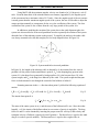
The first step in designing the wind alignment plate was generating a free-body diagram
of the balloon and plate. The free-body diagram is shown below in Figure 12. The center of
gravity and centroid of the balloon are labeled and , respectively. The drag force on the
alignment plate is
and is directed in the same direction as the wind velocity,
. The
axis is attached to the alignment plate axis shown in Figure 11 and rotates with the system at .
The propellers are shown from the side, since the alignment plate and the propellers are
perpendicular. The distance is the moment arm of the drag force about point .
30
[SKY VISION: FINAL DESIGN]
December 7, 2010
Wind velocity
out of page
Balloon
Alignment plate
Propellers (side
view)
Figure 13: Wind alignment free-body diagram
For a preliminary analysis, the alignment plate will be designed as a rectangular rod. The
drag force on the plate, , is
,
Eq. 9
where
is the projected frontal area of the plate. The coefficient of drag is , and is
dependent on the geometry of the alignment plate. Since a fast response is desired, the geometry
will be chosen to provide a large coefficient of drag. The geometry providing the largest drag
coefficient is a rod with a rectangular cross-section with a dimensional ratio of 0.5 (cross-section
height divided by cross-section width) (Cengel and Cimbala 2006). For this geometry, the
coefficient of drag is 2.5.
Since the wind velocity direction stays constant and the plate rotates, the projected frontal
area
of the alignment plate also changes. A relation for the changing area was obtained by
analyzing Figure 14.
Figure 14: Projected frontal area
31
December 7, 2010
[SKY VISION: FINAL DESIGN]
From Figure 14, the projected frontal area as a function of
is
.
Eq. 10
The absolute value of the cosine of is necessary because the projected frontal area is always a
positive quantity. The initial equation of motion (EOM) obtained by summing the moments
about the center of gravity was
,
Eq. 11
where
is the mass of the plate and
is the mass of the balloon. Two stability points are
gleaned from the above EOM:
and
. The first stability point,
, is stable
because small displacements from this point do not induce large deviations from
. The
second stability point, though, is only marginally stable since small disturbances from
cause large deviations from the stability point.
It is immediately evident from Equation 11 that there was no term. Since there was no
term, the damping coefficient is zero, and the response will not decay to the desired stability
point of
. The model initially developed and presented above was therefore inadequate, as a
term inducing decay towards stability is not present.
The damping in the system arises because of relative velocity between the alignment
plate and the surrounding air. The velocity of the air on the back of the plate causes a drag force
which is proportional to the rotational rate of the system. The drag is demonstrated below in
Figure 15.
Figure 15: System damping
32
December 7, 2010
[SKY VISION: FINAL DESIGN]
The back wind velocity and back drag on the alignment plate are represented by
and ,
respectively. The distance to the point of action of both forces is . The
frame rotates with
the system. The velocity of the air at the back of the alignment plate is then
.
The magnitude of the force
Eq. 12
is therefore
.
Eq. 13
Summing the moments about O yields the following result:
.
Eq. 14
The absolute value term on the term compensates for the fact that the direction of the moment
caused by changes when becomes greater then
. The time response of Equation 14 can
be found by solving the equation using the ordinary differential equation solvers in MATLAB.
The MATLAB code used to solve the EOM is provided in Appendix F. The time response is
given below in Figure 16.
Figure 16: Time response of wind alignment plate
33
December 7, 2010
[SKY VISION: FINAL DESIGN]
The wind alignment plate geometry used to generate Figure 16 is contained in the
MATLAB code in Appendix F. After adjusting the geometries in the MATLAB code and
observing the results, it was found that decreasing the moment arm of the alignment plate
decreased the time till the peak was reached, but increased the magnitude of the oscillations
about equilibrium. A value of one meter was found to provide the best balance between initial
response time till peak and magnitude of oscillation about equilibrium.
The material used to construct the alignment plate needs to be as light-weight as possible;
for this reason, Styrofoam will be used to create the alignment plate.
Image Stability: Stabilization Concerns
The effect of the motion of the system (particularly the oscillation about equilibrium)
induced by the wind alignment plate must be addressed. In order to gage the effect of the motion
on image stability, the response time of the
azimuth rotation motor of the imaging system
(see Mechanical Imagine Design) must be compared to the angular velocity of the system, ,
because these two rotations occur about the same axis.
The largest angular velocity in the system response was found by plotting the angular
velocity of the system versus time using the MATLAB code provided in Appendix F. The plot is
provided below in Figure 17.
Maximum angular velocity
Figure 17: Angular velocity of system
34
December 7, 2010
[SKY VISION: FINAL DESIGN]
Using MATLAB, the maximum angular velocity was found to be 2.81 degrees/s, or 0.05
rad/s. From the data sheet of the azimuth rotation servomotor (Appendix H), the angular speed
of the servomotor has a maximum value of 9.52 rad/s. Since the angular speed of the servomotor
is much greater than the maximum angular speed of the system, the user will be able to adjust the
camera position manually to compensate for the very slow oscillation of the system. The slow
oscillation of the system is also evident from the very large period of the system: 44 s.
In addition to modeling the rotation of the system due to the wind alignment plate, the
system was also modeled as an inverted pendulum in order to quantify the rotation of the system
about the base of the tethering system on the ground. To simplify the analysis, the tether cable
was always assumed to be taut and straight (see free body diagram below in Figure 18).
Figure 18: System modeled as inverted pendulum
In Figure 18, the length of the tethering cable is denoted by , the rotation from the vertical
position is , the point of tether attachment is point ,
is the damping drag present in the
system,
is the thrust force generated by both propellers,
is the buoyant force,
is the
system weight, and
is the drag force induced by the wind. The system weight and buoyant
force are both assumed to act through the centroid of the balloon of radius .
Summing moments in the
motion:
direction about point
yielded the following equation of
.
The inertia about point
Eq. 15
is
Eq. 16
The mass of the entire system is
and the mass of the balloon itself is
Since the tether
length
, the inertia of the balloon about its own center of gravity is negligible. The drag
forces
and
can be obtained by inserting the proper terms for velocity (wind velocity and
rotational velocity of balloon, respectively) into Equation 6. The thrust force is equal to the wind
drag
in order to provide stability. The buoyant force is equal to the weight of the air
35
December 7, 2010
[SKY VISION: FINAL DESIGN]
displaced by the balloon. Using an ordinary differential equation solver in MATLAB, the
response to Equation 15 was obtained (see Appendix F - 1 for MATLAB code used) and shown
below is Figure 19.
Figure 19: System response about tethering attachment
From Figure 19, it is clear that the period of the system is approximately 15 seconds, and that the
maximum value of the angular displacement is approximately 1.7 . Due to a combination of
the slow response of the system (large period) and small angular displacement, the quick
response time of the elevation rotation servomotor (see Appendix H) should suffice to allow the
user to manually compensate for slow disturbances of the image.
Propeller Protection Casing Design
In order to protect both the integrity of the balloon and also the user from the rotating
propeller blades, the propellers will each be surrounded by a cylindrical duct with wire mesh
secured to the front and rear of the cylindrical duct. The diameter of the duct will be 12” (0.305
m), which is slightly larger than the diameter of the propellers.
36
December 7, 2010
[SKY VISION: FINAL DESIGN]
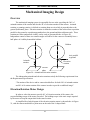
Mechanical Imaging Design
Overview
The mechanical imaging system is responsible for two tasks: providing the 360 of
azimuth rotation of the camera and also the 90 of elevation rotation of the camera. Azimuth
rotation, or panning rotation, is defined as rotation about an axis which is perpendicular to the
ground (horizontal) plane. Elevation rotation is defined as rotation of the camera from a position
parallel to the ground to a position perpendicular to the ground and directed downwards. These
rotations are better understood visually, and as such are presented below in Figure 20.
Independent control of these two rotation angles will allow for the camera to essentially have a
half sphere of visibility beneath the balloon.
Balloon
Balloon
Axis parallel
to ground
Azimuth
rotation
Elevation
rotation
Ground
plane
Figure 20: Azimuth and elevation rotation
The independent azimuth and elevation rotations satisfy the following requirement from
the Requirements Specification:
“The motion of the device and/or camera should allow for both 360 of azimuth rotation
and 90 of elevation rotation of the camera in order to provide a stabilized image”.
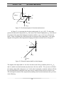
Elevation Rotation Motor Design
In order to select the motor to provide 90 of elevation rotation of the camera, the
required holding torque of the motor is needed. The holding torque is the static torque required
by the motor to keep the output shaft in the same location.
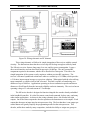
A simplified free-body diagram of the elevation rotation motor is shown below in Figure
21, with the camera modeled as a point mass on the end of the L-shaped shaft.
37
December 7, 2010
Motor
[SKY VISION: FINAL DESIGN]
A
Camera
Figure 21: Free-body diagram of elevation rotation motor
In Figure 21, represents the elevation rotation angle (
), is the torque
generated by the motor output shaft,
is the mass of the camera components,
is the mass of
the portion of the output shaft changing orientation, and the
set of axes is fixed to the
motor. Point A designates the joint between the two portions of the output shaft. A free-body
diagram of the portion of the output shaft changing orientation is shown below in Figure 22.
Figure 22: Elevation rotation shaft free-body diagram
The length of the output shaft is , the force reactions at the fixed, permanent joint are
and , and the associated moments (not shown) are
,
, and . The
axes are fixed to
the rotating output shaft, and rotate at . For the sake of generality, a dynamic analysis will first
be performed and then simplified to the static state by setting all time derivative terms to zero.
The total angular rotation of the output shaft (assuming only elevation rotation) in the
frame
is the following:
38
December 7, 2010
[SKY VISION: FINAL DESIGN]
.
Eq. 17
In order to obtain the angular momentum, the inertia tensor in the
determined. The inertia tensor of the output shaft and camera in the
frame must be
frame is the following:
Eq. 18
Since there are two planes of symmetry, all of the products of inertia drop out (
principal set of axes). The angular momentum,
, is
frame is
Eq. 19
To find the necessary motor torque , the moments must be summed and set equal to the time
derivative of the angular momentum. Point A is a valid location to sum moments since it is not
accelerating (no longer acceptable when azimuth rotation is considered).
Eq. 20
Eq. 21
It can be determined from Figures 21 and 22 that
. Setting the latter two relations equal
exposes the fact that
For the static situation (
, the moment balance
degenerates into
,
Eq. 22
which is the static holding torque required by the elevation rotation motor. The maximum
holding torque occurs at
, and is dependent on the mass of the shaft, length of the
shaft, and mass of the camera. The MATLAB code provided in Appendix G calculates the
holding torque across all values of .
Mechanical Imaging System Component Selection
Three possible mechanisms for accomplishing the elevation and azimuth rotation are
available: stepper motors, brushless DC (direct current) motors, and servomotors. Stepper
motors are available in different angular step rotations per pulse. As step size decreases, control
of the camera location increases in precision. Stepper motors seem to be heavier than
servomotors, but also less complex. The next option for camera rotation is brushless DC motors;
39
December 7, 2010
[SKY VISION: FINAL DESIGN]
these are less suitable for the task at hand since they offer the least amount of control over
position. Also, there is no accurate way of measuring how far the output shaft has rotated. The
last option, servomotors, are feedback controlled motors which receive a pulse-width modulation
(PWM) signal instructing them to rotate the shaft to a specified angular position. Low torque
servomotors are lightweight and generally low in cost, but are also the most complicated of the
rotation mechanisms.
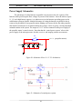
One concern with using a rotating motor is supplying the power to the second motor,
which is rotating relative to the control signal and power supply (assuming power supply is
placed apart from motor). In order to avoid excessive twisting of the signal/power wires, the
rotation range of the azimuth rotation motor will be limited to
. The two-motor system is
shown below in Figure 23.
+
Azimuth rotation motor
Motor mounting bracket
+
-
Camera
Elevation rotation motor
Figure 23: Motor attachment system
Elevation Rotation Motor Design
The first step in determining the torque requirement for the
elevation rotation
servomotor was to determine the inertia of the load on the output shaft of the servomotor. A
diagram of the system is shown below in Figure 24.
Servomotor
9 V Battery
A
Figure 24: Elevation motor design
40
Camera
December 7, 2010
[SKY VISION: FINAL DESIGN]
The torque of the motor is , and the output shaft attaches to the servomotor at point A. The
mass of a 9 V battery (
is 45 g, and the dimensions are 48 mm x 25 mm x 15 mm, and the
mass of the camera (
is 14.2 g (see Appendix K). The camera was approximated as a cube
with side length of 25 mm. Setting
equal to 30 mm and
equal to 70 mm yields a total
inertia tensor about point A of
Eq. 23
Summing the moments about the axis of the output shaft yields following relation, where
equals the angular acceleration of the output shaft:
Eq. 24
Figure 25 demonstrates the relationship between angular acceleration of the output shaft and the
required torque.
Figure 25: Elevation rotation torque
Using the above Figure, a servomotor was found which provided an output torque sufficient to
generate a high angular acceleration (higher angular acceleration equates to faster user response
time, and thus increases image stability). The servomotor selected was a Hitec HS-81 Standard
Micro RC Servomotor (see Appendix H for data sheet).
Azimuth Rotation Motor Design
The next step in the design of the mechanical portion of the imaging system is the design
of the azimuth rotation motor. The inertia that the azimuth rotation motor is required to rotate
only differs by the inertia added by the elevation rotation servomotor (which is very small due to
the small dimensions and mass of the servomotor) because the elevation rotation motor will be
41
December 7, 2010
[SKY VISION: FINAL DESIGN]
connected directly onto the output shaft of the azimuth rotation motor. The additional inertia
contributed by the elevation rotation servomotor is
Eq. 25
where the mass of the servomotor is denoted by
inertia are
and
.
, and the dimensions relative to the
Since the torque generated by the elevation rotation servomotor far exceeded the
maximum (see discussion following Figure 25), and the load on the azimuth rotation motor only
differs slightly
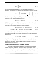
Image Stabilization
The problem of image stabilization can be broken into two categories: image noise due to
high frequency vibration and image drift caused by oscillations of the balloon. The high
frequency vibration of the system is caused by the high rate of rotation of the propellers. Slight
imbalance in the propeller blade can transmit large vibration to the rest of the system.
Oscillations of the balloon, however, are caused by displacement of the balloon due to varying,
periodic, random wind force. The approach towards solving each of these problems is very
different.
The task of eliminating high frequency vibration is simple in comparison to the task of
maintaining image stability caused by oscillations of the platform. The problem of reducing high
frequency vibration transmission can be visualized theoretically by modeling the camera and
propeller assemblies (motor, propeller, and protective casing) as single degree of freedom (DOF)
masses attached to ground by a joint with stiffness and damping . The simplified system is
shown below in Figure 26.
Figure 26: Simplified model for camera and propeller assemblies
42
December 7, 2010
[SKY VISION: FINAL DESIGN]
The propeller assemblies can be modeled as a simple mass which is being forced by
; the periodic forcing is caused by a rotating unbalanced mass. The frequency of the forcing
can be modeled as approximately equal to the rotation rate of the propeller (the unbalanced
mass). In this case, a vibration damping system can be added to remove mechanical energy from
the vibration in the form of heat. The imaging system can be modeled as a mass having a
moving base (
). The damping system in both cases can be thought of as a vibration isolation
system, where the goal is to minimize the force ( ) transmitted through to the base.
Transmissibility is defined as
Eq. 26
The magnitude of the actual periodic force is , which occurs at a frequency of . The
damping ratio depends on the mass of the system, the natural frequency , and the damping
coefficient . Important image stabilization attributes can be obtained from making observations
of the frequency response of the transmissibility. The non-dimensional response of the system
shown in Figure 26 is shown below in Figure 27 for varying values of . See Appendix I for the
MATLAB code used to generate Figure 27.
Resonance (bad)
Increasing damping
ratio (good)
Figure 27: Transmissibility
43
December 7, 2010
[SKY VISION: FINAL DESIGN]
Since the goal is to minimize transmissibility, it is desirable to have low damping
coefficients and low natural frequencies. The worst possible scenario occurs when the natural
frequency is equal to the driving frequency; at this point, the transmitted force becomes much
larger than the actual driving force, causing large disturbances in the system. The solution to the
high frequency vibration problem is therefore to change the system parameters to decrease the
natural frequency and also change the damping to increase the value of . This can be
accomplished by changing the mounting infrastructure of the stabilization units and imaging
system by using materials specifically designed for vibration isolation, such as Sorbothane
(Appendix J).
The manufacturer of the Hitec HS-81 servomotor provides an accessory kit for attaching
the servomotors to the supporting structure which comes with rubber dampers designed to mount
onto the side bolt connections on the servomotor (see Appendix J – 1). Since the actual
excitation frequency causing the high frequency vibration of the system is unknown and can only
be measured via testing, matching material properties of a damper material to the characteristics
of the excitation provides little useful design information. For this reason, the rubber dampers
included in the servomotor accessory kit will be used to damp the high frequency vibration in the
system. If it is discovered during testing that the dampers are not fulfilling their purpose, further
analysis will be performed and a second material selected to provide damping. The simplicity
and very low cost of rubber dampers permit the adaptation of the design at a late stage, during
testing.
44
December 7, 2010
[SKY VISION: FINAL DESIGN]
Electrical Imaging Design
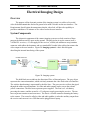
Overview
The purpose of the electronic portion of the imaging system is to collect a live aerial
video feed and transmit that feed to the ground to be made viewable on the user interface. The
Requirements Specification document states that the video feed will have the capability to
provide a minimum of 30 minutes of live video feed to the user interface.
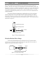
System Components
The electronic component of the camera imaging system as a whole consists of three
parts on the balloon and five parts on the ground. The parts in the air are the camera itself, a
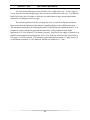
2.4GHz PLL receiver, a 12 volt supply for the receiver, a SMA (sub millimeter array) antenna
connector with rubber duck antenna, and two standard RCA audio/video cables that connect the
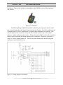
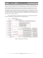
video output to the user interface. Figure 28: Imaging system is a basic block diagram
describing the internal interfacing of the system.
Coaxial Connector
Receiver
Video
Audio
9 Volts
AUX to USB
Camera
12 Volts
Figure 28: Imaging system
The bold black arrows indicate the direction of flow of data and power. The gray object
represents the camera/transmitter, which wirelessly transmits the video feed to the user interface.
The wireless broadcasting is represented by the blue lines. The green receiver collects the signal
through the rubber encased antenna. Its video and audio outputs can be seen as the red and
yellow connections. The blue boxes represent power supplies. The first is a 9 volt battery
powering the camera, and the second is a 12 volt power supply powering the receiver. The tan
boxes represent connectors and converters. The first is a coaxial connector fastening the battery
to the camera. The second is called a video and audio grabber; it takes the auxiliary output from
the receiver and converts it to a USB that can be plugged into a laptop.
45
December 7, 2010
[SKY VISION: FINAL DESIGN]
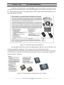
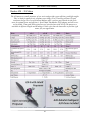
Camera Selection
The specific camera chosen is provided by boostervision.com (see Appendix K). The
criteria for camera selection consisted of factors of weight, size, image quality, wireless range,
price, and availability. The following decision matrix demonstrates the justification for choosing
the 2.4GHz BoosterVision GearCam.
Table 3: Decision matrix for camera selection
Category
Weight
Price
0.4
Weight
0.2
Wireless Range
0.2
Video Quality
0.2
Totals:
1
BoosterVision
4
5
5
3
Pencil Eraser Cam
2
5
3
3
Zoom Cam
1
2
1
4
GearCam DVR
3
4
1
5
4.2
3
1.8
3.2
The features include a small size and light weight 2.4 GHz wireless mini color camera.
The camera also includes audio from a built in microphone. However, the audio feature will not
be utilized by the system. The device has low power consumption and needs only a 9 volt
battery for power. The size is 20 mm (W) by 20mm (H) by 20mm (D). These dimensions are
equivalent to the size of a dime which makes the device small enough to be suitable for the
aircraft. The field of view of the camera is 60 degrees, and it provides CMOS 380 TV lines of
resolution. The range is said to be 91.44 to 213.36 meters (300 to 700 feet) in the air on an
aircraft by the manufacturer. The camera transmission distance was successfully tested; the
range was found to be greater than 45.72 meters (150 feet) outdoors on the ground. The zoom
on the camera must be adjusted manually by twisting the lens with a small tool. The solution to
the focusing complication is to focus the camera at infinity; this is the method used by cheap
disposable cameras. This method will allow all objects at a significant distance to be in focus.
Because objects from a distance of approximately 36.6 meters (120 feet) will be recorded, this
method will provide adequate focus for the imaging system. The operation time of the camera
was also tested using a new 9 volt battery; the operation time was found to be greater than one
hour. These results surpass the requirement of 30 minutes of live video feed.
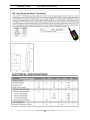
Receiver
The BoosterVision camera includes a no tuning needed PLL (Phase-locked Loop)
receiver. A phase-locked loop is a control system that tries to generate an output signal whose
phase is related to the phase of the input “reference” signal. The end goal of this control process
is to keep the input phases matched. It has a SMA (Sub millimeter Array) antenna connector
with rubber duck antenna. The input to this component is the wirelessly transmitted 2.4 GHz
video and audio feed. It also requires a 12 volt power supply. The output is the auxiliary
46
December 7, 2010
[SKY VISION: FINAL DESIGN]
connections. A USB video and audio grabber will be needed to convert these auxiliary
connections into a format that can be used by the laptop portion of the user interface.
47
December 7, 2010
[SKY VISION: FINAL DESIGN]
Platform Design
System Overview
The platform design consists of the infrastructure to secure the subsystems to the balloon
and the balloon itself. The balloon must be a lighter-than-air system in order to rise on its own
without the aid of the stabilization system. The main purpose of the balloon is to assist the user
in getting the camera to the desired elevation specified by the user. Some of the factors that
helped to determine the size of the balloon included the weights of the components needed on the
infrastructure of the balloon and also the amount of helium gas needed in the balloon.
Helium Gas Design
Two potential choices for lifting gas were compared to decide which would be used to
raise the balloon: hydrogen or helium. The principle governing the mass a certain body can lift
when immersed in a fluid is determined by Archimedes‟ Principle, which states that the buoyant
force exerted on a body is equal and opposite to the weight of the volume of fluid the body
displaces (the buoyant force acts through the centroid of the displaced volume of fluid). After
performing a dynamic analysis of a spherical balloon immersed in air, it was evident that the
amount of mass the balloon could lift was proportional to the difference in density between the
air
and the lifting gas
(with the proportionality factor being the volume of the displaced
air).
.
Eq. 27
Figure 29 shows a comparison of the densities of hydrogen, helium, and air over a wide
temperature range. When the density of hydrogen and helium were compared to the density of
air (shown in Figure 29), there was only a slight difference; therefore, for the same volume
balloon, hydrogen and helium can lift almost the same mass (refer to this quantity as static lift
potential). Figure 30 demonstrates the static lift potential for a spherical balloon with a one
meter radius. It is clear from the figure that the lift potential of both gases is very similar.
48
[SKY VISION: FINAL DESIGN]
December 7, 2010
Densities of Useful Gases @ 1 atm
1.600
1.400
Density (kg/m^3)
1.200
1.000
0.800
Air
0.600
Helium
0.400
Hydrogen
0.200
0.000
-40
-30
-20
-10
0
10
20
30
40
Temperature (°C)
Figure 29: Densities of air, helium and hydrogen at 1 atm.
Static Lift Potential
1.6000
Static Lift Potential (kg/m^3)
1.4000
1.2000
1.0000
0.8000
Helium
0.6000
Hydrogen
0.4000
0.2000
0.0000
-40
-30
-20
-10
0
10
20
30
40
Temperature (°C)
Figure 30: Static lift potential of helium and hydrogen.
Hydrogen is a highly inflammable gas, the presence of which creates substantial hazards
when working with it. Helium, however, continues to increase in price for unknown reasons.
Helium was chosen for use as the lifting gas because of the high safety concerns associated with
49
[SKY VISION: FINAL DESIGN]
December 7, 2010
hydrogen. Airgas Company (located in Searcy, Arkansas) provided the best quote on helium at
$104.00 per tank plus $0.40 per day of rental for a 220 cubic feet tank.
Platform Lift Potential
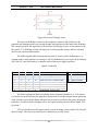
Figure 31: Balloon lift potential diagram
is the total mass of the system including the mass of the supporting and attachment
infrastructure. The density of air (
is proportional to the air temperature and pressure; the
relationship is provided in Equation 28. The specific air constant (R), for air is 0.287 kJ/kg·K.
The specific air constant for helium is 2.077 kJ/kg·K. The average temperature of Searcy,
Arkansas in April, when the balloon will be tested, is 20° C (US Climate Data). It is assumed
that since the system operates outdoors then the air pressure is the standard air pressure, or
101.325 kPa (1 atm). It can be inferred from Figure 32 and Equation 28 that the density of air
does not significantly change as the temperature varies within reasonable environmental limits.
Eq. 28
50
[SKY VISION: FINAL DESIGN]
December 7, 2010
Temperature of the Air vs. Density of Air
1.6
1.4
Density (kg/m^3)
1.2
1
0.8
0.6
0.4
0.2
0
-30
-20
-10
0
10
20
30
40
Temperature (Celcuis)
Figure 32: Graph of the density of air compared to the temperature of the air (Engineering Toolbox)
As shown in Figure 33, standard air pressure varies little between 0 m and approximately
152 meters above sea level. Searcy, Arkansas is at approximately 81 meters above sea level
(www.usclimatedata.com). Since the system is only going to rise to a maximum elevation of
36.6 meters above ground (see Requirements Specification), the total elevation above sea level
will be 127 meters. A significant deviation from the original standard air pressure does not occur
until an elevation of 914 meters is reached; since the elevation of Searcy is much less than this,
then it can be deduced that the effect of elevation change on lift capacity is negligible.
Altitude change effects on Standard Air Pressure
Standard Air Pressure (kPa)
102
100
98
96
94
92
90
88
0
200
400
600
800
1000
Altitude (meters)
Figure 33: Altitude change vs. Standard Air Pressure
51
1200
December 7, 2010
[SKY VISION: FINAL DESIGN]
The amount of mass a spherical balloon can lift is proportional to the volume of the
balloon. Since the volume of the balloon is a cubic function of the balloon radius, the amount of
mass the system can lift increases exponentially as the balloon radius increases. Therefore, a
slight increase in the diameter gives a large increase in lifting capabilities (shown in Figure 34).
Maximum System Mass (kg)
Maximum System Mass
5.0000
4.5000
4.0000
3.5000
3.0000
2.5000
2.0000
1.5000
1.0000
0.5000
0.0000
0
0.2
0.4
0.6
0.8
1
1.2
Radius (m)
Figure 34: Maximum lifting capabilities determined by radius of balloon.
The equation to determine the required lifting capability of the balloon is:
Eq. 29
The mass of the system,
, is all the components included on the infrastructure
underneath the balloon. The balloon selected is 2.13 m in diameter (7 ft); see Appendix L. In
order to reduce complexity and weight, the balloon will be designed to be lighter-than-air (rise
on its own) rather than neutrally buoyant (buoyant force equal to system weight); this will
eliminate the need for the propulsion system to lift the balloon, thus eliminating the motor
needed to rotate the propellers to the vertical direction. Since the weight of the balloon itself is
approximately 2.3 kg, the estimated lifting capability for the balloon is approximately 2.9 kg (a
massless 1 meter radius helium balloon can lift 4.5 kg).
The system mass includes the mass of the imaging system, stabilization system, power
system, wires, material to hold the components, shafts to move the camera and propellers, etc.
The mass of the components are summarized in Table 4.
52
December 7, 2010
[SKY VISION: FINAL DESIGN]
Table 4: System component weights.
Component
Power Supply
Balloon
Stabilization system
Camera
0.9144 meters (3 feet) PVC
Tethering cable
Other electrical components
Camera Motors
Mass (g)
763
2268
110
85
218
498
300
33.2
The combined mass of the system is therefore estimated to be 4275.2 grams. Equation 29
estimates a 2.13 m diameter balloon to be capable of lifting 5254 grams; since the system mass is
predicted to be less than this value, the system will indeed be lighter-than-air.
Attachment Infrastructure Design
On the platform infrastructure, the two locations most important to consider are going to
be where the tether is attached and where the propellers are attached. The infrastructure has to
be able to support the combined 10 N thrust force generated by the propellers. Also, the
infrastructure has to withstand the tethering force. These issues will be considered when
choosing the material to construct the platform and also the methods of attachment. The material
selected for the infrastructure is PVC. A finite element analysis (FEA) shows the connection to
the tether and to the propeller assemblies will withstand the force from the propeller assemblies.
The results of the analysis are shown in Figures 35 and 36. The yield strength of PVC is
approximately 55.15 MPa (Engineering Toolbox). The maximum stress on the infrastructure is
shown in Figure 35 to be 3.8 MPa, yielding a factor of safety is 14. There is a 5 N force at each
end of the pipe where the four bolts are connected to the PVC pipe. The stress could be reduced
by shortening the length of the PVC, if needed. The PVC is 1.27 cm diameter (1/2 inch). The
deflection of the infrastructure due to the 10 N force is minimal. The deflection is approximately
0.00716 meters, as shown in Figure 36.
53
December 7, 2010
[SKY VISION: FINAL DESIGN]
Figure 35: Stress analysis of the PVC pipe.
Figure 36: Deflection of the pipe from the 10 N force.
The actual attachment of the motor and propeller combination to the PVC is
accomplished using bolts. There is a bracket attached to the back of the motor (see Appendix E)
for Hacker A20-20L motor) which then can be attached with four screws onto an aluminum
circle cut-out. Two bolts will hold the aluminum to the PVC. The attachment is shown in
Figures 37 and 38.
54
December 7, 2010
[SKY VISION: FINAL DESIGN]
Figure 37: Propeller and Motor attachment to the PVC.
Figure 38: Attachment of stabilization system.
The bottom of the balloon has four connections for a payload attachment; these
attachments are a feature of the balloon purchased. The four attachments are shown in Figure 39
The mounting rings will be connected onto the balloon infrastructure via a rigid attachment.
55
December 7, 2010
[SKY VISION: FINAL DESIGN]
Figure 39: Infrastructure attachment to balloon.
The camera will be attached to a system of two motors. The first motor will be bolted to
the PVC with two screws. The second motor will be attached with a bracket to the first motor,
and the camera itself will be glued to the rotating arm attached to the second motor‟s output
shaft. The 9 V battery will be attached via a battery case for the purpose of changing the battery
once the battery loses charge. These connections are shown in Figure 40.
Azimuth rotation
servomotor
9 V battery
Elevation rotation
servomotor
Camera
Figure 40: Attachment of camera and 9 V battery to the second motor.
There are also five lithium polymer batteries that will be attached to the PVC
infrastructure. Each battery will be placed into a metal case to fit the battery. The case will be
screwed into the PVC; this is shown in Figures 41 and 42 .
56
December 7, 2010
[SKY VISION: FINAL DESIGN]
Figure 41: Placement of five lithium polymer batteries.
Figure 42: Another view of the placement of the batteries.
The entire system design of the platform infrastructure is shown in Figures 43, 44, and
45. These figures show where the placements of the components are going to be. Also, the
symmetry of the design is evident; symmetry is beneficial, as it keeps the center of gravity along
the center of the balloon.
Figure 43: Attachment of major subsystems.
57
December 7, 2010
[SKY VISION: FINAL DESIGN]
Figure 44: Bottom view of the infrastructure design.
Figure 45: Comparison between platform infrastructure and balloon dimensions.
58
[SKY VISION: FINAL DESIGN]
December 7, 2010
Tethering Design
Overview
The purpose of the tethering system is to secure the system to the ground and also to reel
in the platform from the desired elevation. The two factors primarily affecting the design of the
tethering system are how much the entire system will weigh and also ensuring the system is
small enough to fit in the 0.425 meters (15 cubic feet) requirement. The tethering cable must be
able to support the stress generated by the balloon pulling upwards and the user reeling the
system in. It can be assumed that the vertical acceleration of the system is negligible, since the
user can dictate the rate at which the balloon rises by adjusting how much tethering cable is
released.
System Components
1. Tethering cable
2. Reeling mechanism and supporting infrastructure
Tethering Cable Tension
The relation to determine the needed strength of the tethering cable is shown in Equation
30. Since the acceleration of the system is negligible when the system has reached the desired
height, the system can be modeled as a static system, where the sum of the forces is zero. The
tension, , determines the required strength of the tethering cable material.
Eq. 30
The mass of the system, provided in the platform design, is 4037.2 grams and the radius
of the balloon chosen is 1.065 meters. Also, the density of air is 1.204 kg/m3 and the density of
helium is 0.1664 kg/m3. With this equation, the tension in the cable is 91.1 N. The material
selected for the tethering cable is 6.35 mm diameter (0.25 inch) hollow braid polypropylene.
This material can withstand up to 4404 N (990 lbf).
The force on the reeling system is calculated by subtracting the system weight from the
buoyant force cause by the displacement of air by the balloon. Equations 31 and 32 show the
required reeling force calculations:
Eq. 31
Eq. 32
59
December 7, 2010
[SKY VISION: FINAL DESIGN]
From Equations 31 and 32, the net force on the reeling system is 11.9 N; this is also the required
force of the user to reel in the system. A Bayco deluxe reel with stand will be used as the
structure; it is shown in Figure 46.
Figure 46. Reeling system for tether rope.
As stated in the FAA regulations provided in Appendix A, a bright colored flag must be
attached for every 15.24 meters (50 feet) of tethering cable released. Plastic pennant flags will
be attached to the tethering cable to fulfill this requirement, and since only 36.6 m of cable is
required, only two pennants will be needed. The mass of the plastic pennant flags is negligible.
60
December 7, 2010
[SKY VISION: FINAL DESIGN]
Power Supply Design
Overview
The objective of the power supply is to fulfill the following requirement from the
Requirements Specification document:
“The power system should allow for a minimum of 1 hour flight time and also a
minimum of 30 minutes of live video, not necessarily continuous, from the imaging
system.”
The components of the system requiring power are the brushless motors driving the propellers,
the servomotors providing mechanical imaging rotation, the microprocessor, the receiver, and the
decoder which transforms the user input signal from the receiver to a form useable by the
microprocessor.
The components consuming the largest amount of power are the motors of the
stabilization system. The servomotors providing the 360 azimuth rotation and 90 elevation
rotation of the imaging system consume the next highest amount of power. The microprocessor,
receiver, and decoder all consume far less power than either of the previously mentioned
components. Note that the interface between the power supply and the communication system is
referenced in the Communication System Design.
Selection of Power Supply for Propeller Motors
The motors driving the propellers of the stabilization system require large amounts of
power due to the high rotation rates of the motor output shafts. The battery required to provide
power to the motors must be capable of meeting the power requirements necessary to generate
the required amount of thrust.
The primary concern in the selection of the power supply for the propeller motors was the
need for a battery capable of providing substantial amounts of current (in the range of 10 - 12 A).
To address this concern, two options were available; the first option was to utilize a conventional
battery with a high capacity, on the order of approximately 10 – 12
. The second option was
to use a battery with a high discharge rate. Due to concern over the maximum weight of the
system, it was deemed more feasible to use a battery with a high discharge rate rather than a
large capacity. Also, a battery with a high discharge rate can provide large bursts of current only
when large gusts of winds demand it. In order to keep operating costs low for the users of Sky
Vision, the batteries selected to provide power must be rechargeable.
Several alternatives were examined in order to select the design which best fit the needs
presented in the prior discussion. The first alternative was to provide power through the
61
December 7, 2010
[SKY VISION: FINAL DESIGN]
tethering cable and utilize a lead-acid battery on the ground to provide the required power.
However, it was found that the weight of 36.3 m of wire of a gage large enough to handle 10 –
12 A of current was substantially large, and far exceeded the lift capabilities of the balloon.
Also, the cost of both the cable and the lead acid battery exceeded the cost of batteries light
enough to be mounted on the balloon.
The next option for power supply was lithium polymer batteries. Lithium polymer
batteries were selected to provide power to the stabilization system for several primary reasons.
First, lithium polymer batteries have a high energy density: they can provide large amounts of
power for small battery weights. Due to this, the weight of the lithium polymer batteries was
smaller than any of the aforementioned options. Next, the batteries are capable of being easily
recharged. Also, the manufacturer of the propeller motors recommends using an 11.1 V, 3 cell
lithium polymer battery pack for providing power to the motors.
The specific battery selected to provide power to the stabilization system is an 11.1 V, 3
cell (3S) lithium polymer battery with a battery capacity of 2.5
and a maximum discharge
rate of 10 – 12 C (this is discussed in relation to the worst case scenario for power requirements
and run time in the following pages). The mass of each battery is 175 g. The 3S lithium
polymer battery is shown below in Figure 47. The dimensions of each battery pack are 58mm x
95mm x 19mm.
Figure 47: 11.1 V, 3S lithium polymer battery
The next step in the design of the power supply was to determine the quantity of 11.1 V,
3S lithium polymer battery packs needed to provide the correct amount of power to the
stabilization system
Estimating Required Power of Propeller Motors
The power consumed by each motor driving the propellers in order to generate 5 N of
thrust each is 130 W (see thrust calculators on in Stabilization System Design). 5 N of thrust
corresponds to the worst case scenario corresponding to the wind speed causing the maximum
drag on the balloon (wind speed of approximately 3 m/s).
62
December 7, 2010
[SKY VISION: FINAL DESIGN]
The first step in determining battery life was to determine a relationship between supplied
power and battery longevity. Battery longevity for a 2.5
battery can be obtained via the
following formula:
Eq. 33
In Equation 33,
is the power supplied by the battery to the motors (dependent on thrust
force needed), the voltage of the batteries is constant at 11.1 V, and the capacity of the batteries
is 2.5
. Table 5 provides data for battery longevity versus wind speed, where the power
supplied to each motor is proportional to the wind speed on the balloon.
Table 5: Battery longevity
Wind Speed (m/s)
3.0
2.8
2.5
2.3
2.0
1.8
1.5
1.3
1.0
0.8
0.5
0.3
0.0
Battery Longevity for one 2.5 A h
batteries per motor (minutes)
12.5
13.6
15.0
16.7
18.8
21.4
25.0
30.0
37.5
50.0
75.0
150.0
NA
Battery Longevity for two 2.5 A h
batteries per motor (minutes)
25.0
27.3
30.0
33.3
37.5
42.9
50.0
60.0
75.0
100.0
150.0
300.0
NA
It is evident from Table 5 that a runtime of 60 minutes (as specified in the Requirements
Specification) can only be obtained via a single 2.5
battery when the average wind speed
over the entire hour is approximately 0.7 m/s (1.5 mi/h).
Table 6 contains average wind speed data per month for Little Rock, Arkansas. It is clear
from the table that the average wind speed in March thru April (when testing occurs) is
approximately 4.0 m/s.
63
December 7, 2010
[SKY VISION: FINAL DESIGN]
Table 6: Average wind speed for Little Rock, AR
Average Wind Speed
(mph)
January
8.4
February
8.9
March
9.6
April
9
May
7.6
June
7.1
July
6.7
August
6.3
September 6.6
October
6.8
November 8
December 8.1
Average Wind Speed
(m/s)
3.8
4.0
4.3
4.0
3.4
3.2
3.0
2.8
3.0
3.0
3.6
3.6
Though the average wind speed in the aforementioned months is approximately 4.0 m/s,
the actual wind speed varies about the average speed according to the Rayleigh distribution
(Gipe 2004). The Rayleigh distribution for wind speed is
Eq. 34
where
is the wind speed bin width, is the speed of the wind speed bin, and
is the
average wind speed. Plotting the above function in MATLAB for a wind speed of 4 m/s yields
the following distribution for Little Rock, Arkansas.
64
December 7, 2010
[SKY VISION: FINAL DESIGN]
Figure 48: Rayleigh wind distribution for average wind speed of 4 m/s
Summing the frequency of occurrences of a range of wind speed bins provides the
frequency of occurrence of a range of wind speeds. Since 3 m/s is a worst case scenario,
summing from 2.5 m/s to 3 m/s will give a frequency of occurrence of the worst case wind speed
range. The frequency of occurrence for a range 2.5 m/s to 3 m/s is 11% (found using
MATLAB). Therefore, even on a day with an average wind speed of 4 m/s, the worst case range
occurs only 11% of the total time. Since the drag force of the wind on the balloon drops
drastically at 3 m/s, wind values between 4 and 5 m/s only require low values of power to the
propeller motors to stabilize against wind. Dividing the runtime calculated in Table 5 for a worst
case scenario of 3 m/s winds by the frequency of occurrence for the worst case range of 2.5 – 3
m/s wind range gives an approximate expected runtime of 112.6 minutes.
The approximation, however, assumed that the propeller motors are not running except
when the wind speed is in the worst case scenario range and also that each propeller motor is
connected to a single 11.1 V, 2.5
battery. To account for compensating for wind speeds at
all times (not merely the worst case scenario), it is assumed that the influence of all other wind
speeds on battery longevity is equal to the influence on battery longevity of the worst case wind
speed range. Since both wind speed ranges have the same effect, the prior mentioned run time
accounting for only the worst case range is essentially halved, causing a run time of 56.3
minutes.
Since the projected run time is less than that dictated by the Requirements Specification
(60 min.), further capacity must be added to the power supply system. The further capacity will
be accomplished by adding another battery of equal capacity to each propeller motor. The
addition of more power than necessary will incorporate a factor of safety into the power supply
65
December 7, 2010
[SKY VISION: FINAL DESIGN]
system, which will allow for days on which the wind speed distribution does not fit the Rayleigh
probability density function curve and instead has a higher frequency of occurrence of the worst
case wind speed range.
Estimating Power Required by Other Power Consuming Systems
The four other systems requiring power (other than the camera, which operates on its
own 9 V power supply) are the two servomotors providing imaging rotation (6 V and 0.5 A, see
Appendix H), the microprocessor (5 V and 48 mA, see Appendix N), the decoder for the
controller receiver (5 V and 670 A, see Appendix T), and the controller receiver itself (5 V and
5.2 mA, see Appendix T). The combined power of all the aforementioned components is 6.3 W;
therefore, 30 minutes of run time for the system requires 3.15
.
Due to the light weight of the lithium polymer batteries, a lithium polymer battery will
also be used to provide power to all other power consuming components. Since only 3.15
.
are needed, another 3 cell lithium polymer battery with lower energy (11.1 V 830 mAh) will be
used, as opposed to the 3 cell lithium polymer batteries used by the stabilization system. The
battery selected for providing power to all other power consuming systems is a 3 cell 11.1 V,
830 mAh lithium polymer battery with the following capacity in
:
Eq.
Since the required capacity was 3.15
, the 3 cell 11.1 V 830 mAh lithium polymer battery
will be capable of providing power for the required 30 minutes of run time. The battery selected
is shown below in Figure 49.
Figure 49: 11.1 V 830 mAh, 3S lithium polymer battery
The mass of the battery is 63 g and the dimensions are 36 x 53 x 21 mm. The cost of the battery
is $10.00.
66
[SKY VISION: FINAL DESIGN]
December 7, 2010
Power Supply Schematics
The advantage of wiring batteries in parallel is an increase in the
capacity of the
batteries while preserving the same voltage of just one of the batteries. Since the motors require
11.1 V and a high battery capacity, it is judicious to wire the batteries providing power to the
stabilization system in parallel. Another advantage of wiring the batteries in parallel is that it
removes the possibility of one propeller motor running out of power before the other propeller;
this situation would cause a net moment about the system‟s center of gravity, causing unwanted
azimuth rotation of the system. The output of 11.1 V will be connected to the power supply of
the propeller motor‟s control circuits. Note that that the „central power system‟ refers to the
power supply of the microprocessor, decoder, receiver, and imaging rotation servomotors.
J1
(propeller
motors)
11.1 V (propeller
motor
)
Key = A
11.1 V
V1
11.1 V
V3
V5
V8
11.1 V 11.1 V
Figure 50: Schematic of four 11.1 V 2.5 Ah batteries
Figure 51: Schematic of central power system
67
December 7, 2010
[SKY VISION: FINAL DESIGN]
Voltage regulators will be used to drop the 11.1 V down to 6 V and 5 V. Voltage
regulator MC7806 will be used to drop the voltage from 11.1 V to 6 V, and voltage regulator
LM7805 will be used to drop the voltage from 11.1 V to 5 V (see Appendix P for data sheets of
voltage regulators). .The two servomotors providing imaging rotation will draw the 6 V from the
power supply circuit (Figure 51). The output of 6V will connect to the power supply of
servomotors control circuit. The 5 V power branch will provide the necessary power to
microprocessor and the decoder for the controller receiver. The output will connect with the
power supply pin of microprocessor and the decoder.
The reason that the smaller capacity battery will not be in parallel with the other four
batteries was obtained by analyzing the work down by the previous blimp senior design group.
The prior group found that electrical interference noise from the propeller motors is significant,
and will interfere with the camera: to minimize this noise, the power supply of the imaging
rotation motors and microprocessor will be separated from the power supply of the propeller
motors.
Although the central battery can also provide the surplus power to the propeller motors
when they are in parallel, the surplus power of (9.21Wh-3.15Wh)/2=3.03Wh for each propeller
motors is insignificant when compared to the maximum of 130W drawn by each propeller motor.
Therefore, the best scenario is to provide power to the central power system from a source
independent of the propulsion motor‟s power supply.
Wiring Selection
One issue with using large amounts of current is that conventionally available 18 gage
wire cannot withstand the current required to drive the stabilization motors. A lower gage of
wire is therefore needed for use in the stabilization system. Selecting an appropriate gage for the
wiring depends on several factors. The first factor is the type of wiring desired, as the type of
wiring dictates how much current the wire gage can withstand before failure. The two types of
wiring are power transmission wiring and chassis wiring. Power transmission wiring is wiring in
which open air is allowed to dissipate the heat generated by the wire. Chassis wiring, however,
is wiring in which the space is enclosed and the heat is not dissipated, leading to increased wire
temperatures and corresponding increases in internal wire resistance. Since the system will be in
the air and the wiring external, the wire gage should be selected based on the current estimates
for power transmission wiring.
The next criteria influencing wiring selection is the internal resistance of the wire gage.
Higher gage of wire (smaller diameter wiring) typically involves higher values of resistance per
unit length. Large values of resistance per unit length are undesirable, as they introduce
transmitted power loss through conversion of electrical energy to thermal energy.
68
December 7, 2010
[SKY VISION: FINAL DESIGN]
The last criteria influencing wiring selection is the weight of the wire. A lower gage of
wire is much heavier than a higher gage, due to the increased diameter of the wire. It is therefore
beneficial, for the sake of weight, to select the wire which meets a large current requirement,
without far exceeding the necessary gage.
The current requirement for the wire gage was set at a value exceeding the maximum
burst current from the lithium polymer batteries supplying power to the stabilization system.
The maximum current draw of each propeller motor is specified by the manufacturer to be 15 A
continuous current, though the projected maximum draw of the propeller motors in this
application is 12 A (to generate 5 N of thrust per motor). Since the power supply of batteries is in
parallel, the maximum current through the wire is 30A. From the American Wire Gage Table, a
wire gage of 7 will be selected. The maximum power transmission current of 7 gage wire is 30
A, the internal resistance is 1.634 ohms/km, and the wire diameter is 3.7 mm.
69
December 7, 2010
[SKY VISION: FINAL DESIGN]
Communication System Design
Overview
The purpose of the communication system is to maneuver the balloon and camera
positioning according to user inputs from the ground. The communication process begins when
the user manipulates a hand held controller. These movements are converted to a signal that is
wirelessly transmitted at a frequency originally planned to be 2.4GHz. This signal is picked up
by a receiver mounted on the system. This receiver is interfaced with a microprocessor which
interprets the signal from the ground. The microprocessor outputs the appropriate pulse width
modulated signal to the motor control circuit. The motor control circuit sends power in the
correct direction through the propeller motors and camera rotation motors causing the system
and camera to respond according to the user‟s instruction.
System Components
The communication system can be broken down into three major components. The first
component consists of the hand held radio controller and includes both the transmitter and
receiver. A microprocessor makes up the second major component. It must be programmed to
interface with the receiver and interpret the input signal into outputs that can be used by the
motors. The third major component consists of all the necessary motor control circuitry which
sends the necessary power to the motors. The figure below is a basic block diagram describing
the original internal interfacing of this system before significant design changes were made.
Figure 52: Communication system
70
December 7, 2010
[SKY VISION: FINAL DESIGN]
Controller
The original controller chosen is the Exceed RC 2.4GHz Radio Control System. This
programmable device was thought to be perfect for the system because it is typically used for
small RC helicopters. The low cost of approximately 45 dollars made it financially attractive as
well. This component will take the user manipulations and transmit them to the system.
Figure 53: Initial RC controller
Features include a six channel transmitter complete set with receiver. Controls allow for
complete forward/backward, left/right, up/down, and pitch control. It uses a rotor head for
precision and smooth movements; it claims it can display great stability and precision for 3D
flight; this stability may aid the system greatly with the task locking the camera onto a stationary
object on the ground particularly during windy situations. The system uses frequency
modulation and a frequency of 2.4GHz. It is capable of simultaneously controlling three servo
motors. A main concern is whether it will be possible to control all four motors with the device.
If only three motors can be controlled at a time, then perhaps one of the three signals can be
utilized as a “switching” signal. If this signal was set one way, then the other two signals could
control the propeller motors. If the signal were set the other way, then the remaining signals
could control the camera motion. Because the device is programmable, it will be possible to
modify the signal output to conform to the system needs. Another solution to having three
outputs would be to control both propeller motors using the same signal.
All of the above assumptions made it seem that the communication system was basically
designed except for the programming of the device. This assumption turned out to be false upon
further research. First of all, upon contacting the manufacturer of the camera, it was made clear
that some 2.4GHz RC controllers interfere with the 2.4GHz GearCam. Upon researching the
71
December 7, 2010
[SKY VISION: FINAL DESIGN]
non-interfering 2.4GHz radios, it was discovered that one would cost between three and five
hundred dollars. Second of all, research lead to the realization that the device was designed for
a very specific application. The tutorials for programming the device made it evident that user
manipulation of a single control would cause outputs on multiple receiver channels. For the sake
of simplicity in programming balloon control, it is desirable for each input from the user to affect
one output. However, with the Exceed RC, each input will necessarily produce multiple outputs.
The fact that the device was programmable led to the false conclusion that it could be
conveniently modified to fit the needs of Sky Vision. Therefore, a new control option needed to
be chosen for the project.
Alternative Controller Selection
The following decision matrix was formulated after extensive research of available
transmitters and receivers. The main factors considered in the purchasing decision included
adequate number of transmission channels, adequate transmission range, and a price low enough
to fit within Sky Vision’s budget.
Table 7: Decision Matrix for transmitter
The OTX by Linx Technologies was selected as the replacement transmitter for the
system (see Appendix S); it is also called the MS long range handheld transmitter. The handheld
transmitter cost less than $40.00, had a transmission range of 304 m (1000 ft), and comes with an
eight button option. This device is available to purchase in a number of different available
frequencies. The linxtechnologies.com website gives a very helpful recommendation for this
exact topic. The website says 315MHz is primarily used for remote keyless entry and garage
door openers. As a result, this frequency is somewhat crowded. In addition, the FCC allowed
power is lower than for other frequencies, and selection of antennas is limited. 418MHz is a
good to use in the U.S. as it is not very crowed. Therefore, it has less chance of encountering
interference and performs better. 433.92MHz is not good in the U.S. due to the chance of
interference from amateur radio and the nearby pager band. 902-928MHz modules are more
expensive due to the more complex filtering and modulation required for link reliability at these
higher frequencies. The option of 2.4GHz was immediately ruled out due to the risk of camera
72
December 7, 2010
[SKY VISION: FINAL DESIGN]
interference. Based on the website recommendations, the 418MHz version of the transmitter
was selected.
Figure 54: Transmitter
The MS Long-Range Handheld transmitter is ideal for general-purpose remote control
and command applications that require longer transmission distances. It will be configured with
8 buttons to meet Sky Vision control needs. It contains an on-board MS Series encoder. This
encoder enhances ease of use and security and allows instant creation of up to
unique
addresses without cumbersome dip switches. When paired with a MS Series decoder, transmitter
identity can be determined and button functions can be established. The unit is powered by a
single 3V CR2032 lithium button cell. The below diagram illustrates the internal wiring and
organization of the handheld device.
Figure 55: Wiring diagram of transmitter
73
December 7, 2010
[SKY VISION: FINAL DESIGN]
In addition to the transmitter, a corresponding receiver and decoder are necessary to pick
up and utilize the transmitted signal. The selected transmitter was available to purchase in a full
kit. The kit in the below figure cost approximately $150.00 USD, which unfortunately does not
fall within budget limitations.
Figure 56: Transmitter master development kit
Even though this all inclusive kit is not within budget, it did allow for an efficient way of
selecting compatible components. The necessary parts were selected based on the
recommendations laid out in both this development system and also on the website. First of all,
a LR series receiver and MS series decoder were selected. They are shown below along with a
wiring schematic of the pins.
Figure 57: Decoder features (left) and receiver IC (right)
74
December 7, 2010
[SKY VISION: FINAL DESIGN]
Figure 58: Wiring schematic and IC dimensions for receiver and decoder
This wiring schematic will allow for simple integration of the receiver with the control
circuitry. The dimensions show that the receiver chip will be large enough to solder by hand.
The LR series receiver features long range, low cost, and low power consumption. It uses a
direct serial interface and can detect data at rates up to 10,000 bps. The only external RF
component required is the antenna, which will be described at a later point. This allows for
simple integration of the system even by engineers without previous RF experience. The
receiver‟s advanced synthesized architecture achieves a sensitivity of -112dBm, which provides
a 5-10 times improvement in range over previous solutions. When paired with the selected long
range transmitter, a reliable wireless link is formed. This link is capable of transferring over
distances of up to 3000 feet. Applications operating at slower transmission speeds and shorter
distances will still benefit from the increased reliability and noise immunity. The receiver has an
operating voltage of 5 volts and current of 5.2 milliamps.
The MS series decoder is designed to function alongside the encoder already embedded
in the handheld controller. It is ideal for remote control and command, keyless entry, and many
other similar applications. As shown in the wiring schematic above, the decoder has eight
outputs. On each of these outputs the decoder reproduces the button states on its outputs. Each
output then becomes an input into the microprocessor chip. The fact that there is one output per
control button will greatly simplify the programming needed on the microprocessor. This
decoder, unlike those made by many competitors, includes the ability to assign user groups to
75
December 7, 2010
[SKY VISION: FINAL DESIGN]
individual output lines. It can recognize up to 40 different encoders, but only one encoder will
be utilized by the Sky Vision system. Outputs can be either latched or momentary. Like the
receiver, the decoder features low voltage supply of 5 volts and low current consumption of only
670 micro amps.
An antenna is a necessary part of the communication system. The specific type
recommended for the 418 transmitter is a CW Series Whip Antenna. The dimensions of this part
are shown below.
Figure 59: CW Series Whip Antenna
This ¼-wave antenna delivers good performance in a rugged and attractive package. It
comes available with standard SMA (sub millimeter array) connectors or RP-SMA (reverse
polarity SMA) connectors. It detects a center frequency of 418MHz and is recommended for
frequencies in the range of 380 to 450MHz. A wide variety of matching connectors make
numerous mounting options possible. This antenna‟s output is connected to the input on pin 16
of the LR series receiver IC.
The figure below represents an updated block diagram for the communication system.
76
[SKY VISION: FINAL DESIGN]
December 7, 2010
Figure 60: Updated communication system
Microprocessor Selection
The microprocessor selection process was very simple for the project. There were a
number of convincing factors that led to the final choice of the DSPIC30F6015. The main
factors considered were the availability of a programmer, the benefit of working together with
other teams, and the functionality of the microprocessor in regards to motor control. The
following figure outlines this decision process.
Figure 61: Microprocessor decision matrix
The final goal is that the microprocessor will have two main functions. Both functions
will be a direct result of user inputs onto the handheld transmitter device. The first function will
control the output sent to the stabilization motors. The signal sent to the stabilization motors will
be a pulse width modulated signal. This signal will be sent to a power MOSFET to allow current
77
December 7, 2010
[SKY VISION: FINAL DESIGN]
to flow to the stabilization servo motors. Different duty cycles will be selected to allow high,
medium, or low power supply levels to be sent to these motors. The level to be sent to the motor
will be determined by the user based on the amount of wind drag on the balloon. The second
function will be to control the direction the camera is pointing. These outputs will be sent into
an H-bridge to allow for changes in the direction of camera rotation. The microprocessor will be
programmed using the PIC programmer owned by the Harding Engineering Department. It will
be mounted on a Schmart-board prototyping board (see Appendix O) for ease in interfacing with
the other communication components.
A flow chart describing the operation of the microprocessor is shown below in Figure 62,
and a pin-out diagram of the microprocessor is provided in Figure 63.
Figure 62: Microprocessor flow chart
78
December 7, 2010
[SKY VISION: FINAL DESIGN]
Figure 63: Microprocessor pin out diagram
Motor Control
The simplicity and familiarity of an H-Bridge to control the motors powering the
stabilization system makes the use of an H-Bridge an attractive option for motor control. The
issue with the H-Bridge circuit is that the propellers in the stabilization system require as much
as 10 Amps. As of yet, two H-Bridge circuits that claim to handle 10 A have been found.
Though using an IC version of an H-Bridge would simplify the design, no IC versions of an HBridge have been found which can handle the current requirements of the system. A generic HBridge circuit is shown below in Figure 64.
79
[SKY VISION: FINAL DESIGN]
December 7, 2010
Figure 64: Generic H-Bridge circuit
The reason an H-Bridge is attractive for component control is that it allows for the
propellers and imaging motors to be turned in either direction based on the state of the H-Bridge.
The control system for this application will need four of H-Bridge circuits, as four motors are on
the system. Two H-Bridge circuits will send power to the propeller motors, and two will send
power to the camera rotation motors.
The following truth table demonstrates the result of various switch configurations. A
warning must be made against ever closing S1 and S3 simultaneously (see Figure 64 for labeling
of S1 and S3), since this results in a complete short of the power supply to ground.
Table 8: Truth table
S1
1
0
0
0
1
1
x
S2
0
1
0
1
0
1
x
S3
0
1
0
0
1
x
1
S4
1
0
0
1
0
x
1
Result
motor moves right
motor moves left
motor runs free - slows to stop
motor brakes
motor brakes
not allowed - short circuit
not allowed - short circuit
Key
1 switch closed
0 switch open
x doesn't matter
The following diagram shows an H bridge that is designed to handle 10 A. This feature
is crucial to our project because the propellers must be able to provide adequate thrust against the
wind. In order to provide this thrust, adequate power must be provided to the motors driving the
propellers. In order to deliver adequate power, the control circuitry must be able to handle 10 A
of current.
TTL type Q and inverted Q inputs control a classic H-bridge circuit, rated at 50 volts and
about 10 amps. The circuit can control power and direction of a DC motor.
80
December 7, 2010
[SKY VISION: FINAL DESIGN]
Figure 65: H-Bridge circuit to be used
81
December 7, 2010
[SKY VISION: FINAL DESIGN]
User Interface Design
The user interface consists of a device on which the user can view the live video feed
transmitted from the imaging system on the balloon. Initially, it was thought that an LCD screen
and corresponding circuitry would be used to view the live video feed. However, it was found
that analog output to USB output connectors were cost effective, simple to use, and readily
available (see Appendix Q); see Figure 66 below.
Figure 66: Analog to USB connector
The USB connector supports video formatting and high quality video resolution, and
complies with USB Specification Rev. 2.0 (see Appendix Q). Due to the ease with which the
video format will be converted to USB, a user supplied laptop computer will be used to view the
live video feed.
The handheld radio controller utilized by the user to send control signals to the system is
described in detail in the Communication System Design.
82
December 7, 2010
[SKY VISION: FINAL DESIGN]
Budget
83
[SKY VISION: FINAL DESIGN]
December 7, 2010
Budget Overview
Table 9. Budget overview table.
Initial Projected Current Projected Spent
Stabilization
$110.00
$107.80
$107.80
$82.00
$124.13
$124.13
$135.00
$103.95
$73.95
$50.00
$19.98
$11.50
$350.00
$395.90
$286.30
Communication
$50.00
$69.82
$69.82
User Interface
$48.00
$9.00
MicroProcessor and Circuitry
$40.00
$51.09
Imaging System
Main Power Supply
Tether
Platform
Contingency
$135.00
$51.09
$118.33 Percent Spent
78.78%
Total
$1,000.00
$1,000.00
$724.59
The initial budget estimate of the stabilization system was a fairly accurate estimate, as
the difference between the funds spent and funds estimated was only $3. The estimated camera
budget was inaccurate, because the imaging rotation servomotor costs were not included in the
initial budget estimate. The power supply was approximately $30 under the initial amount
estimated, because lithium polymer batteries were found to be cheaper than initially expected.
The tethering system had a much less cost than that anticipated, because the decision was made
to power the system using batteries on the balloon rather than sending power through the
tethering cable. The platform was approximately $50 more than anticipated, for two primary
reasons: helium was more expensive than estimated, and also the cost of the balloon was
increased due to selecting a balloon with premade load attachments. The communication budget
is approximately the same as that initially estimated. The user interface was much cheaper than
initially estimated, because a user-supplied laptop will be used as the user interface, eliminating
the need for an LCD display.
The estimated budget for the control circuitry (combination microprocessor and
transmitter) was very inaccurate, due to the decision to use a microprocessor to control the
stabilization system and mechanical imaging system.
84
December 7, 2010
[SKY VISION: FINAL DESIGN]
Subsystem Budgets
Imaging System
Component
Camera
Camera
Receiver
Receiver
Camera
Connector
Motors
Motor Attachment
Item to Purchase
2.4 ghz Mini GearCam
shipping
no tuning needed PLL receiver
12 volt ac/dc supply
9 volt battery clip
Mini Coaxial Plug (size H)
Hitec HS-81
Hitec HS-81 Kit
Quantity
1
1
1
1
1
1
2
2
Total
Total
$69.95
$8.95
$0.00
$0.00
$0.00
$3.23
$34.00
$8.00
$124.13
Vendor
boostervision.com
boostervision.com
boostervision.com
boostervision.com
boostervision.com
Radio Shack
rctoys.com
rctoys.com
Stabilization System
Component
Motors
Propeller
Casing
Mounting
Motors
Propellers
Item to Purchase
Hacker A20-20L
APC SF 10 x 4.7 inch
Quantity
2
2
2
shipping
shipping included above
1
1
Total
Total
Vendor
$89.90 rctoys.com
$7.90 rctoys.com
undecided
undecided
$10.00 rctoys.com
$0.00 rctoys.com
$107.80
Main Power Supply
Component
Camera Pwr
Motor Pwr
Motor Pwr
Receiver Pwr
Motor Pwr
Item to Purchase
9 Volt Battery
Lipo; 11.1V / 2500mah; 10-12C;
Shipping
12 Volt AC/DC Supply
Lipo; 11.1V / 830mah; 10-12C;
85
Quantity
2
4
1
1
1
Total
$6.00
$80.00
$7.95
$0.00
$10.00
Total
$103.95
Vendor
Kroger
maxxprod.com
maxxprod.com
boostervision.com
maxxprod.com
December 7, 2010
[SKY VISION: FINAL DESIGN]
Tether System
Component
Item to Purchase
Reel
Bayco Deluxe 150' Reel with Stand
Tether Cord 1/4 polypropylene (120 feet)
Tether Cord shipping
Quantity
1
1
1
Total
Vendor
$8.48 Lowes
$6.00 knotandrope.com
$5.50 knotandrope.com
Total
$19.98
Platform System
Mounting
Balloon
Balloon
Helium
Helium
PVC Pipe 0.5 inch by 5 feet
7 feet Urethane Balloon
shipping
220 cubic feet tank
Rental fee per day
1
1
1
1
14
Total
$1.30
$265.00
$20.00
$104.00
$5.60
Lowes
southernballoonworks.com
southernballoonworks.com
AirGas
AirGas
$395.90
Communication System
Component
Transmitter
Decoder
Receiver
Attena
Connector
Connector
Item to Purchase
Quantity
MS Long Rang Handheld Transmitter
1
MS series decoder
2
LR Series Receiver
2
CW series whip attena
1
Attena connector
1
Attena connector
1
Total
86
Total
$32.80
$6.20
$19.60
$5.74
$2.30
$3.18
$69.82
Vendor
linxtechnologies.com
linxtechnologies.com
linxtechnologies.com
linxtechnologies.com
linxtechnologies.com
linxtechnologies.com
December 7, 2010
[SKY VISION: FINAL DESIGN]
User Interface System
Component
AUX to USB
AUS to USB
screen
Item to Purchase
Quantity
EasyCAP (captures video & audio)
1
free shipping
1
user's own laptop
1
Total
Total
Vendor
$9.00 dealextreme.com
$0.00 dealextreme.com
$0.00 user
$9.00
Microprocessor and Control Circuitry
Component
Item to Purchase
Microprocessor free sample DSPIC30F6015
Evaluation Board SchmartBoard 202 - 0011 - 01
87
Quantity
3
2
Total
Vendor
$0.00 microchip.com
$51.09 schmartboard.com
Total
$51.09
December 7, 2010
[SKY VISION: FINAL DESIGN]
Project Management
88
December 7, 2010
[SKY VISION: FINAL DESIGN]
Fall 2010 Schedule Analysis
Many unanticipated elements influenced the realization of the Fall 2010 Schedule (Gantt
Chart, Work-Breakdown Schedule, and Network Diagram). The primary factor influencing the
realization of the Fall 2010 Schedule was the influence of recursive design elements and system
interdependencies.
The main design of all of the subsystems was directly influenced by the design of at least
one other subsystem. For example, the power system relied on the design of the stabilization
system. However, the thrust generated by the propellers hinged upon how much power they
were supplied.
Many system interdependencies, such as the example provided above, shifted the design
from a linear process to a recursive process. The design had to be based on estimates of other
systems, the influencing system design was then edited, and those edits were factored into the
design of the systems contingent on the edited system. For this reason, the Network Diagram
was changed to add an arrow leaving the „System Design and Analysis‟ and into the beginning of
the subsystem designs. The addition of the recursive element of design caused the estimated
times for design to be drastically altered.
Another primary change was the addition of an Image Stabilization task. Image
stabilization was a factor in the design of most of the subsystems; no one single subsystem
existed which cured the problem of image stability. Therefore, a separate task was added which
addressed the problem of image stability as a task inherent to all subsystem designs. Also, the
task of designing the tether cable to transmit power was removed from the Work-Breakdown
Schedule.
The schedule analysis for the Spring Semester appears to still remain unchanged, as
image stability has been designed into all the other subsystems to be built, rather than being built
as its own physical/electrical system. Changes to the schedules for the Spring Semester are a
reflection of design decision changes; ex., powering the system via system mounted batteries
rather than the tethering cable transmitting power.
89
[SKY VISION: FINAL DESIGN]
Fall 2010
Gantt Chart
December 7, 2010
90
December 7, 2010
[SKY VISION: FINAL DESIGN]
Fall 2010 Work-Breakdown Schedule
ID
Activity
Description
Deliverables/ Checkpoints
F1.0
F 2.0
Project
Management
Documentation
F 3.0
Project Choice
Description of team member
task completion
Engineering notebooks, A3
reports, and design reports
Problem specification report
F4.0
Requirements
Specification
System Design
& Project Plan
Ensure project is completed
correctly and on time
Ensure changes and progress
is recorded
Decide on which problem
solution to pursue
Complete set of all system
requirements
Report of semester goals and
deadlines, along with
functional descriptions of
subsystems
Complete design of
subsystems
F 5.0
F6.0
Device Design
F6.1
Platform
Design
Design of balloon and
mounting infrastructure
F6.2
Camera Design
F
6.2.1
Imaging Design
Design of imaging system
and camera rotation system
Design of camera system to
provide live video feed
F
6.2.2
Camera
Rotation Design
Design of system to rotate
camera 90
F6.3
Stabilization
Design
Stabilize, rotate, and translate
device
F6.4
Power Design
Design power system to
power device
F6.5
Communication
Design
Design system to transmit
user inputs/outputs to/from
device
F6.6
Tether Design
Design system to secure
device
F6.7
User Interface
Design
F7.0
System Design
and Analysis
Final Design
Design system to receive
inputs and display live video
feed
Ensure correct integration of
subsystems and order parts
The final design of system
and subsystems
F8.0
Requirements specification
document
System Design and Project Plan
final report
Component selection and
performance specifications. of
subsystems
Type of balloon; performance
specifications of balloon; design
of mounting brackets
Camera selection; camera
rotation design
Camera selection and
performance specifications; data
transmitter and receiver
Motor and mounting system
selection; performance
specifications
Stabilization unit design and
selection; movement
specifications; mounting design;
performance specifications
Battery selection; power
distribution design; performance
specifications
Communication method
selected; control circuitry
design; performance
specifications
Selection of tethering cord;
reeling device design;
performance specifications
User interface control circuitry
designed; performance
specifications
Final system design and
documentation of parts ordering
Final Design Report (includes
schematics and project model)
Please note that ‘performance specifications’ includes test results
91
Duration
(days)
Aug. 23rd
– Dec. 9th
Aug. 23rd
– Dec. 9th
Aug. 23rd
– Sept. 7th
Sept. 7th –
Sept 28th
Sept. 28th
– Oct. 12th
People
Oct. 12th –
Nov. 16th
Ph, P,
J, C
Oct. 12th –
Nov. 2nd
C (1),
Ph (2)
Oct. 12th –
Oct. 26th
Oct. 12th –
Oct. 26th
J, Ph
Oct. 12th –
Oct. 26th
Ph
Oct. 12th Oct. 26th
Ph (1),
C (2)
Nov. 2nd –
Nov. 16th
P (1), J
(2)
Oct. 26th –
Nov. 9th
J (1), P
(2)
Nov. 2nd –
Nov. 16th
C (1),
Ph (2)
Oct. 22nd
– Nov. 9th
P (1), J
(2)
Nov. 9th –
Dec. 7th
Nov. 9th –
Dec. 9th
Ph, P,
J, C
Ph, P,
J, C
Ph
Ph, P,
J, C
Ph, P,
J, C
Ph, P,
J, C
Ph, P,
J, C
J
[SKY VISION: FINAL DESIGN]
Fall 2010
Network Diagram
December 7, 2010
92
[SKY VISION: FINAL DESIGN]
Spring 2011
Gantt Chart
December 7, 2010
93
December 7, 2010
[SKY VISION: FINAL DESIGN]
Spring 2011 Work-Breakdown Schedule
ID
Activity
Description
S 1.0
Project
Management
S 2.0
Documentation
S 3.0
Device Build
S 3.1
Platform Build
Ensure project is
completed correctly and on
time
Ensure changes and
progress is recorded
Complete builds of
subsystems
Connect mounting
infrastructure to balloon
S 3.2
Camera Build
Build imaging system and
camera rotation system
S
3.2.1
S
3.2.2
Imaging Build
Build camera system
Camera
Rotation Build
Build of camera rotation
system
S 3.3
Stabilization
Build
Build of stabilization
system to stabilize device
S 3.4
Power Build
Build power system to
power device
S 3.5
Communication
Build
Build system to transmit
user inputs/outputs to/from
device
S 3.6
Tether Build
Build system to secure
device to ground
S 3.7
User Interface
Program
S 4.0
Device Testing
S 4.1
Platform
Testing
Program software to
receive inputs and display
live video feed
Complete testing of each
subsystem
Test the platform to ensure
it can support subsystems
S 4.2
Camera Testing
S
4.2.1
Imaging
Testing
S
Camera
Ensure camera can provide
live feed and rotate through
specified angle
Ensure the camera can
provide satisfactory video
feed
Ensure camera can rotate
Deliverables/
Checkpoints
Description of team member
task completion
Duration
(days)
Jan. 18th –
May 5th
People
Engineering notebooks, A3
reports, design reports
All of subsystems connected as
specified by design
Mounting brackets for tether,
stabilization system, and
imaging system attached to
balloon
Imaging and camera rotation
subsystems connected. Camera
control circuitry built for both
imaging and camera rotation
Receiver/transmitting circuitry
built and connected to camera
Camera mounted to elevation
rotation shaft and motor. Motor
connected to control circuitry
Stabilization units built,
assembled, and mounted to
platform frame
Power distribution system and
voltage regulating system built
and connected to battery
Remote control circuitry built
and ready to be mounted to user
interface and aerial portion of
platform
Reeling mechanism connected to
rope. Rope attachment to
balloon mechanism built
Laptop displays live video feed
and records.
Jan 18th –
May 5th
Jan. 18th –
Feb. 22nd
Jan. 18th –
Feb. 8th
Ph, P,
J, C
Ph, P,
J, C
C (1),
Ph (2)
Jan. 18th –
Feb. 1st
J, Ph
Jan. 18th –
Jan. 25th
Jan 25th –
Feb. 1st
J
Jan 18th –
Feb. 1st
Ph (1),
C (2)
Feb. 8th –
Feb. 22nd
P (1), J
(2)
Feb. 1st –
Feb. 15th
J (1), P
(2)
Feb. 8th –
Feb. 22nd
C (1),
Ph (2)
Feb. 1st –
Feb. 15th
P (1), J
(2)
Test results of subsystems;
modification recommendations
Results of balloon lift and
stability tests; modification
recommendations
Results of camera imaging and
rotation tests; modification
recommendations
Results of imaging testing;
modification recommendations
Feb. 1st –
Mar. 8th
Feb. 8th –
Feb. 22nd
Ph, P,
J, C
C (1),
Ph (2)
Feb. 1st –
Feb. 15th
J, Ph
Feb. 1st –
Feb. 15th
J
Actual range of rotation
Feb. 1st –
Ph
94
Ph
Ph
December 7, 2010
4.2.2
S 4.3
Rotation
Testing
Stabilization
Testing
[SKY VISION: FINAL DESIGN]
specified elevation range
Ensure stabilization units
compensate for wind drag
and angular deflection
Ensure power outputs can
provide power for all
subsystems
Ensure system can
communicate to device at
max. altitude and
receive/transmit user
signals
Ensure tether can support
system
Ensure user interface can
transmit/receive signal
from/to communication
system
S 4.4
Power Testing
S 4.5
Communication
Testing
S 4.6
Tether Testing
S 4.7
User Interface
Testing
S 5.0
Project Status
Statement of project status
S 6.0
S 8.0
System
Integration
System Testing
and
Modifications
User’s Manual
S 9.0
Final Report
Integrate subsystems to
ensure correct functionality
Testing of total integrated
system and corresponding
modifications
Instructions to user on how
to operate system
Presentation of final device
and system capabilities
S 7.0
specified; modification
recommendations
Actual thrust output quantified;
modification recommendations
Feb. 15th
Feb. 1st –
Feb. 15th
P (1),
C (2)
Actual power output quantified;
modification recommendations
Feb. 22nd –
Mar. 8th
P (1), J
(2)
Actual communication range
quantified; modification
recommendations
Feb. 15th –
Mar. 1st
J (1), P
(2)
Actual reeling force quantified;
modification recommendations
Test proper response of balloon
to user input on the user
interface. Verify live video
feed; modification
recommendations
Project status report
Feb. 22nd –
Mar. 8th
Feb 15th –
Mar. 1st
C (1),
Ph (2)
P (1), J
(2)
Feb. 15th –
April 5th
Mar 1st –
Mar. 29th
Mar. 22nd –
April 12th
Ph, P,
J, C
Ph, P,
J, C
Ph, P,
J, C
April 19th –
May 3rd
April 12th –
May 3rd
Ph, P,
J, C
Ph, P,
J, C
Provides fully integrated
prototype to test
Complete system prototype
User‟s manual report
Final report document
95
[SKY VISION: FINAL DESIGN]
Network Diagram Spring 2011
December 7, 2010
96
December 7, 2010
[SKY VISION: FINAL DESIGN]
References
97
December 7, 2010
[SKY VISION: FINAL DESIGN]
"Air - Altitude, Density, and Specific Volume." Engineering Toolbox. Web. 25 Nov. 2010.
<http://www.engineeringtoolbox.com/air-altitude-density-volume-d_195.html>.
"American Wire Gauge Table and AWG Electrical Current Load Limits with Skin Depth
Frequencies." PowerStream Power Supplies and Chargers for OEMs in a Hurry. Web.
06 Dec. 2010. <http://www.powerstream.com/Wire_Size.htm>.
"Climate Searcy - Arkansas - Climate Graph." Climate - United States - Monthly Averages. Web.
25 Nov. 2010. <http://www.usclimatedata.com/climate.php?location=USAR0508>.
Gipe, Paul. Wind Power: Renewable Energy for Home, Farm, and Business. 1st Edition, Chelsea
Green Publishing Company
Y.A. Cengel, Cimbala, Fluid Mechanics: A Practical Approach, Third Edition, McGraw Hill.
98
December 7, 2010
[SKY VISION: FINAL DESIGN]
Appendices
99
December 7, 2010
[SKY VISION: FINAL DESIGN]
Appendix A
FAA Regulations
100
December 7, 2010
[SKY VISION: FINAL DESIGN]
Subpart A - General
101.1 Applicability.
(a) This part prescribes rules governing the operation in the United States, of the following:
(1) Except as provided for in 101.7, any balloon that is moored to the surface of the earth or an
object thereon and that has a diameter of more than 6 feet or a gas capacity of more than 115
cubic feet.
(2) Except as provided for in 101.7, any kite that weighs more than 5 pounds and is intended to
be flown at the end of a rope or cable.
(3) Any unmanned rocket except:
(i) Aerial firework displays; and,
(ii) Model rockets:
(a) Using not more than four ounces of propellant;
(b) Using a slow-burning propellant;
(c) Made of paper, wood, or breakable plastic, containing no substantial metal parts and
weighing not more than 16 ounces, including the propellant; and
(d) Operated in a manner that does not create a hazard to persons, property, or other aircraft.
(4) Except as provided for in 101.7, any unmanned free balloon that(i) Carries a payload package that weighs more than four pounds and has a weight/size ratio
of more than three ounces per square inch on any surface of the package, determined by dividing
the total weight in ounces of the payload package by the area in square inches of its smallest
surface;
(ii) Carries a payload package that weighs more than six pounds;
(iii) Carries a payload, of two or more packages, that weighs more than 12 pounds; or
(iv) Uses a rope or other device for suspension of the payload that requires an impact force of
more than 50 pounds to separate the suspended payload from the balloon.
(b) For the purposes of this part, a gyroglider attached to a vehicle on the surface of the earth
is considered to be a kite.
[Doc. No. 1580, 28 FR 6721, June 29, 1963, as amended by Amdt. 101-1,
101
December 7, 2010
[SKY VISION: FINAL DESIGN]
29 FR 46, Jan. 3, 1964; Amdt. 101-3, 35 FR 8213, May 26, 1970]
101.3 Waivers.
No person may conduct operations that require a deviation from this part except under a
certificate of waiver issued by the Administrator.
[Doc. No. 1580, 28 FR 6721, June 29, 1963]
101.5 Operations in prohibited or restricted areas.
No person may operate a moored balloon, kite, unmanned rocket, or unmanned free balloon in a
prohibited or restricted area unless he has permission from the using or controlling agency, as
appropriate.
[Amdt. 101-1, 29 FR 46, Jan. 3, 1964]
101.7 Hazardous operations.
(a) No person may operate any moored balloon, kite, unmanned rocket, or unmanned free
balloon in a manner that creates a hazard to other persons, or their property.
(b) No person operating any moored balloon, kite, unmanned rocket, or unmanned free balloon
may allow an object to be dropped there from, if such action creates a hazard to other persons or
their property.
(Sec. 6(c), Department of Transportation Act (49 U.S.C. 1655(c)))
[Doc. No. 12800, Amdt. 101-4, 39 FR 22252, June 21, 1974]
Subpart B - Moored Balloons and Kites
Source: Docket No. 1580, 28 FR 6722 June 29, 1963, unless otherwise noted.
101.11 Applicability.
This subpart applies to the operation of moored balloons and kites. However, a person operating
a moored balloon or kite within a restricted area must comply only with 101.19 and with
additional
limitations imposed by the using or controlling agency, as appropriate.
101.13 Operating limitations.
(a) Except as provided in paragraph (b) of this section, no person may operate a moored
balloon or kite102
December 7, 2010
[SKY VISION: FINAL DESIGN]
(1) Less than 500 feet from the base of any cloud;
(2) More than 500 feet above the surface of the earth;
(3) From an area where the ground visibility is less than three miles; or
(4) Within five miles of the boundary of any airport.
(b) Paragraph (a) of this section does not apply to the operation of a balloon or kite below the
top of any structure and within 250 feet of it, if that shielded operation does not obscure any
lighting on the structure.
101.15 Notice requirements.
No person may operate an unshielded moored balloon or kite more than 150 feet above the
surface of the earth unless, at least 24 hours before beginning the operation, he gives the
following information to
the FAA ATC facility that is nearest to the place of intended operation:
(a) The names and addresses of the owners and operators.
(b) The size of the balloon or the size and weight of the kite.
(c) The location of the operation.
(d) The height above the surface of the earth at which the balloon or kite is to be operated.
(e) The date, time, and duration of the operation.
101.17 Lighting and marking requirements.
(a) No person may operate a moored balloon or kite, between sunset and sunrise unless the
balloon or kite, and its mooring lines, are lighted so as to give a visual warning equal to that
required for obstructions to air navigation in the FAA publication "Obstruction Marking and
Lighting" .
(b) No person may operate a moored balloon or kite between sunrise and sunset unless its
mooring lines have colored pennants or streamers attached at not more than 50 foot intervals
beginning at 150 feet above the surface of the earth and visible for at least one mile.
(Sec. 6(c), Department of Transportation Act (49 U.S.C. 1655(c)))
[Doc. No. 1580, 28 FR 6722, June 29, 1963, as amended by Amdt. 101-4,
39 FR 22252, June 21, 1974]
103
December 7, 2010
[SKY VISION: FINAL DESIGN]
101.19 Rapid deflation device.
No person may operate a moored balloon unless it has a device that will automatically and
rapidly deflate the balloon if it escapes from its moorings. If the device does not function
properly, the operator shall immediately notify the nearest ATC facility of the location and time
of the escape and the estimated flight path of the balloon.
104
December 7, 2010
[SKY VISION: FINAL DESIGN]
Appendix B
Propeller Justification MATLAB Code
105
December 7, 2010
[SKY VISION: FINAL DESIGN]
% Balloon pitch deflection
syms T p real
Ft = 11.99; % Thrust force from propulsion units (N)
Fd = 12; % Wind force (N)
w = 5*9.81; % system weight (N)
Fb = 6*9.81; % Bouyant force (N)
eq1 = -Ft + Fd - T/sqrt(1 + p^2);
eq2 = Fb - w - T*p/sqrt(1 + p^2);
% Sum of forces in x-direction
% Sum of forces in y-direction
S=solve(eq1,eq2,'T,p');
Tension = vpa(S.T,4);
slope = vpa(S.p,4);
disp(sprintf('Thrust
disp(sprintf('Wind Force
disp(sprintf('System Weight
disp(sprintf('Bouyant Force
disp('
')
disp(sprintf('Tension
disp(sprintf('Tilt
disp(' ')
=
=
=
=
%8.2f
%8.2f
%8.2f
%8.2f
N',double(Ft)))
N',double(Fd)))
N',double(w)))
N',double(Fb)))
= %8.2f N',double(Tension)))
= %8.2f degrees',double(90-atand(slope))))
phi = 90 - atand(slope);
rising_force = Fb - w - Tension*cos(phi);
106
% Lifting force
December 7, 2010
[SKY VISION: FINAL DESIGN]
Appendix C
Maximum Wind Force MATLAB Code
107
December 7, 2010
%%%
%%%
%%%
%%%
%%%
%%%
%%%
%%%
%%%
%%%
%%%
[SKY VISION: FINAL DESIGN]
Wind Force Calculation
This program calculates the average wind force exerted on the
balloon by a constant wind velocity
C_d = drag coefficient
F_wind = 0.5*C_d*p*V^2*A
Assumption: Balloon is spherical
Assumption: P = 1 atm and T = 20 C
clear
T = -20:5:30;
F_max = zeros(length(T),1);
% Air temperature (C)
V_max = zeros(length(T),1);
for i = 1:length(T)
rho = 1.204;
% Density of air (kg/m^3)
v = 8.79302e-8*T(i) + 1.34039e-5; % Kinematic viscosity of air (m^2/s)
V_wind = [0:0.01:5];
% Relative wind speed range on balloon (m/s)
C_d = zeros(length(V_wind),1);
r = 1;
% Radius of balloon (assume spherical (m)
Re = V_wind*2*r/v;
A = pi*r^2;
% Reynolds number for flow over a sphere
% Projected frontal area of spherical balloon
for j = 1:length(V_wind)
if Re(j) <= 4e5
% 4 x 10^5 slightly larger than Re_cr
C_d(j) = 0.5;
% C_d for flow Re < Re_cr
elseif Re(j) > 4e5 && Re(j) < 1e6
C_d(j) = 0.1;
% C_d for flow Re > Re_cr
else
C_d(j) = 0.2;
% C_d for Re > 1e6
end
V_wind_2(j) = V_wind(j)^2;
% Wind speed squared
F_wind(j) = 0.5*C_d(j)*rho*V_wind_2(j)*A; % Wind force (N)
end
[F_max(i), k] = max(F_wind);
V_max(i) = V_wind(k);
end
plot(V_wind,F_wind)
title('Wind Force (N)','fontsize',14)
xlabel('Wind Velocity (m/s)','fontsize',12)
ylabel('Wind Force (N)','fontsize',12)
108
December 7, 2010
[SKY VISION: FINAL DESIGN]
Appendix D
APC10 x 4.7 Propeller Data Sheet
109
December 7, 2010
[SKY VISION: FINAL DESIGN]
APC 10x4.7 SF Slow Flyer Electric RC Airplane Composite Propeller
Product Description:
APC Landing Products Slow Flyer RC electric composite model airplane propeller A10047SF /
LP 10047SF is designed for use with electric rc airplanes. APC Slow Flyer props are not for high
power applications but are specifically crafted for low power use. Includes locating rings in
various sizes and instructions on adaptation procedures.
APC Landing Products electric model airplane propellers have enjoyed strong acceptance and
growth since their introduction in 1989. They are especially popular in rc pattern flying and rc
airplane racing events. The performance and low noise advantages are largely spawned by the
precision methods APC - Landing Products uses to design and manufacture APC electric rc
airplane propellers.
APC 10x4.7 SF Slow Flyer Electric RC Airplane Composite Propeller Specifications
Length: 10 inches
Pitch: 4.7 inches per revolution
Type: Slow Flyer Electric
Material: 1 Piece Composite
Use: Electric RC Airplanes
APC - Landing Products preserves a close rapport with the rc aircraft competition community to
benefit from technical interchange so important to improved rc airplane propeller designs. There
is continuous evolution in rc aircraft design and engine performance. Consequently, propeller
design must continuously evolve as well to keep pace with these improving technologies.
Due to APC's excellent quality and consistent performance APC - Landing Products' rc airplane
propellers are perfect for any electric rc application from parkflyers to 3D aerobatics to scale rc
aircraft.
110
December 7, 2010
[SKY VISION: FINAL DESIGN]
Note: This rc airplane propeller is designed only for use with electric motors. Do not attempt to
use this propeller with glo or gas powered engines.
111
December 7, 2010
[SKY VISION: FINAL DESIGN]
Appendix E
Hacker A20-20L Motor Data Sheet
112
December 7, 2010
[SKY VISION: FINAL DESIGN]
Hacker A20 – 20L Motor
The A20 motors are small outrunner of our series and provides great efficiency and light weight.
They’re ideal for small electric airplanes up to 600g (21oz). Featuring a Slotted 14-pole
outrunner design. The Curved Neodym-Magnets offer a perfect gap from the inside of the
rotor for optimal power and efficiency. Spare shafts, Backmount, Prop adapter and all screws
are included. 3,5mm gold bullet connectors are provided (not with A20-S) The motors are
available in different Lengths and Windings. Please refer data the data tables to find the right
motor for your application.
113
December 7, 2010
[SKY VISION: FINAL DESIGN]
Hacker Motor GmbH
Hummler Str. 5 D-85416 Niederhummel
Phone: +49-8761-752 129 Fax: +49-8761-754 314
email: [email protected]
114
December 7, 2010
[SKY VISION: FINAL DESIGN]
Appendix F
Wind Alignment MATLAB Code
115
December 7, 2010
[SKY VISION: FINAL DESIGN]
mb = 2.5; % Mass of balloon (kg)
R = 1;
% Radius of balloon (m)
mp = 0.1; % Mass of plate (kg)
r = 0.5;
% Moment arm of centroid of drag force (m)
D = 0.05;
% vertical height of plate (m)
L = 2;
% Length of plate (m)
vw = 5;
% Wind velocity (m/s)
pair = 1.204;
% Density of air (kg/m^3)
Ap = D*L;
% Projected frontal area
C_d = 2.5;
% Drag coefficient thickness is L2 Thickness of L2/D = 0.5
%corresponds to C_d of 2.5
j = 2/5*mb*R^2 + 1/12*mp*D^2 + mp*r^2;
% Inertia
% Rectangular rod, projected area still D*L, thickness is L2:
% Thickness of L2/D = 0.5 corresponds to C_d of 2.5
F_d_r = 0.5*C_d*pair*vw^2*Ap*r;
c = F_d_r/j;
c2 = 1/2*pair*Ap*C_d*r^3/j;
t = [0:0.1:150];
%Numerical solution
options = odeset; %Using default options for ode solver
th0 = [0, 0]; %initial conditions on thdot=0 and th=0
[time,th_vals] = ode113(@wind_alignment_fcn, t, th0,options,c,c2);
figure(1)
plot(time,th_vals(:,1),'r');
title('Wind Stability Response','Fontsize',14)
xlabel('Time (s)','Fontsize',12)
ylabel(texlabel('theta (deg)'),'Fontsize',12)
figure(2)
plot(t,th_vals(:,2))
title('Wind Stability Response: Angular Rate of Change','Fontsize',14)
xlabel('Time (s)','Fontsize',12)
ylabel(texlabel('d*theta/dt(deg/s)'),'Fontsize',12)
function dth = wind_alignment_fcn(t, th0, c, c2)
% Need to provide function with th and thdot.
% th(1) is theta itself, and
% th(2) is first derivative of theta
th = th0(1);
thdot = th0(2);
thdot = thdot;
thdoubledot = c*cosd(th)*abs(cosd(th)) - c2*thdot*abs(thdot);
dth = [thdot; thdoubledot];
116
December 7, 2010
[SKY VISION: FINAL DESIGN]
Appendix F – 1
Wind Response MATLAB Code
117
December 7, 2010
[SKY VISION: FINAL DESIGN]
clear
T = -20:5:30;
F_max = zeros(length(T),1);
g = 9.81;
% Air temperature (C)
V_max = zeros(length(T),1);
for i = 1:length(T)
pair = 1.204;
% Density of air (kg/m^3)
v = 8.79302e-8*T(i) + 1.34039e-5; % Kinematic viscosity of air (m^2/s)
V_wind = [0:0.01:5];
% Relative wind speed range on balloon (m/s)
C_d = zeros(length(V_wind),1);
% Drag coefficient
R = 1.065;
% Radius of balloon (assume spherical
(m)
Re = V_wind*2*R/v;
A = pi*R^2;
% Reynolds number for flow over a sphere
% Projected frontal area of spherical balloon
for j = 1:length(V_wind)
if Re(j) <= 4e5
% 4 x 10^5 slightly larger than Re_cr
C_d(j) = 0.5;
% C_d for flow Re < Re_cr
elseif Re(j) > 4e5 && Re(j) < 1e6
C_d(j) = 0.1;
% C_d for flow Re > Re_cr
else
C_d(j) = 0.2;
% C_d for Re > 1e6
end
V_wind_2(j) = V_wind(j)^2;
% Wind speed squared
F_wind(j) = 0.5*C_d(j)*pair*V_wind_2(j)*A; % Wind force (N)
end
end
vw = 0.1;
F_w = -1;
% Desired velocity to analyze motion of balloon
% Initializes force of wind to unrealistic value so it
% will be known if no value is found
for i = 1:length(V_wind)
if V_wind(i) == vw
F_w = F_wind(i);
break
elseif i == length(V_wind) && F_w == -1
error('Wind speed out of specified range')
end
end
F_B = pair*4/3*pi*R^3*g;
%% Buoyant force on balloon
mb = 2.5; % Mass of balloon (kg)
msys = 4; % System mass (kg)
h = 30;
% Height of balloon (m)
I_o = msys*h^2;
% Inertia about tether-ground
c1 = h*F_w/I_o;
c2 = -(F_B - msys*g)*h/I_o;
c3 = -0.3*pair*pi*R^2*h^3/2/I_o;
c4 = -F_w*h/I_o;
% thrust force should be equal to drag force of wind
t = [0:0.01:120];
118
December 7, 2010
[SKY VISION: FINAL DESIGN]
%Numerical solution
options = odeset; %Using default options for ode solver
phi0 = [0, 0]; %initial conditions on thdot=0 and th=0
[time,phi_vals]= ode45(@pendulum_balloon_fcn, t, phi0,options,c1,c2,c3,c4);
plot(time,abs(phi_vals(:,1)),'r');
title('Wind Response','Fontsize',14)
xlabel('Time (s)','Fontsize',12)
ylabel(texlabel('phi (deg)'),'Fontsize',12)
function dphi = pendulum_balloon_fcn(t, phi0, c1, c2, c3, c4)
% Need to provide function with th and thdot.
% th(2) is first derivative of theta
th(1) is theta itself, and
phi = phi0(1);
phidot = phi0(2);
phidot = phidot;
phidoubledot = c2*cos(phi) + c3*phidot*abs(phidot);
% Approximate with no damping
% to obtain max the
dphi = [phidot; phidoubledot];
119
December 7, 2010
[SKY VISION: FINAL DESIGN]
Appendix G
Elevation Rotation Motor Holding Torque MATLAB
Code
120
December 7, 2010
[SKY VISION: FINAL DESIGN]
%%% 90 deg Elevation Rotation Motor Holding Torque
%%%
%%%
This program calculates the holding torque necessary from the
%%%
stepper motor providing the 90 degrees of elevation rotation of the
%%%
camera. An 'L' shaped shaft is attached to the motor output shaft,
%%%
and the camera is attached to the end of the 'L'. The first
%%%
portion of the L shaft is shaft 1, the second portion is shaft 2
%%%
g = 9.81;
% m/s^2
mc = 0.0141;
% Mass of camera (kg)
ms2 = 0.01;
% Mass of shaft 2 (kg)
psi = 0:1.8:90;
% Elevation rotation angle, in increment typical of a
% stepper motor (1.8 deg)
L2 = 0:0.005:0.05;
% Length of shaft 2 (m)
h_torque = g*L2*sind(90)*(0.5*ms2 + mc); % Max torque is when psi = 90
plot(L2, h_torque)
title('Maximum Holding Torque','fontsize', 14)
xlabel('Length of Shaft 2 (m)')
ylabel('Holding Torque (N m)')
h_torque_max = max(h_torque)
% Max Holding torque (N m)
121
December 7, 2010
[SKY VISION: FINAL DESIGN]
Appendix H
Hitec HS-81 Servomotor Datasheet
122
December 7, 2010
[SKY VISION: FINAL DESIGN]
123
December 7, 2010
[SKY VISION: FINAL DESIGN]
Appendix I
Transmissibility MATLAB Code
124
December 7, 2010
[SKY VISION: FINAL DESIGN]
% Transmissibility Curves
w_wn = 0:0.01:3;
z = [0.05;0.10;0.15;0.25;0.50;1];
for i = 1:length(z);
for j = 1:length(w_wn)
x(i,j) = (1 + (2*z(i)*w_wn(j))^2)^0.5./sqrt((1 - w_wn(j)^2)^2 + ...
(2*z(i)*w_wn(j))^2);
end
end
plot(w_wn,x)
title('Transmissibility','Fontsize',14)
xlabel(texlabel('omega/omega_n'),'Fontsize',14)
ylabel(texlabel(' |X(jw)|/A , F_tr/F_0'),'Fontsize',14)
125
December 7, 2010
[SKY VISION: FINAL DESIGN]
Appendix J
Sorbothane Vibration Isolation Material
126
December 7, 2010
[SKY VISION: FINAL DESIGN]
Sorbothane® Polymer Sheet Stock
X-Tra Flex Sheet
X-Tra Flex Sheet is molded with hemispherical bumps. The hemispheres permit the material to
flex more easily and allow for soft deformation under load. Overall sheet thickness is
approximately 0.185-inch. The hemispheres are approximately 0.09 high and 0.12 diameter. XTra Flex sheets are easier to apply to curved and irregular surfaces and provide a softer spring
rate.
Pressure Sensitive Adhesives
Selected Sizes (max width = 6-inches) are offered with Pressure Sensitive Adhesive (PSA) on
one side.
Die Cutting
Sheet stock up to 0.25-inch thick, with or without PSA can be die cut at additional cost. Die cut
materials will have a concave edge. Consult factory on costs.
Water Jet Cutting
Sheet stock of any thickness can be water jet cut. Water jet cut materials will have a clean edge.
Consult factory on costs.
Gaskets
Sorbothane is a popular material for gaskets because of its chemical resistance, conformability
to irregular surfaces, low creep and reusability. Its natural tackiness makes it easy to install.
Gaskets can be knife-cut, scissor-cut, die cut, molded or water jet cut.
Special Sizes, Colors and Thicknesses
The factory can pour special shapes, colors and thicknesses. Tooling costs can be as low as 500
USD per mold. The tooling charge is normally less than your internal fabrication costs for
special work except for the smallest volumes.
Sheet Stock for Vibration Applications
In designing your own vibration mounts from sheet stock keep the following in mind:
More is not better. A large, lightly loaded sheet will have a high spring rate and will not
deflect enough to provide good isolation. Over compression will lead to short service life.
The proper compression range is 3 to 20 per cent depending on the "Shape Factor." Shape
factor is the ratio of contact surface (one side) divided by perimeter area. See page 11 for
calculation of shape factors.
Geometry matters. Small circular pieces and rings "bulge" better than squares and
rectangles. "Bulgeability" makes for better isolation. Use many small discs rather than a
few large rectangles for best vibration isolation performance.
Thickness matters. The thicker the sheet, the lower the natural frequency. You need a
sheet at least one-inch thick to get your natural frequency down to 10 Hertz. (10 Hertz is
your target natural frequency for a 900 RPM motor.)
127
December 7, 2010
[SKY VISION: FINAL DESIGN]
Do not "bolt through" your Sorbothane sheet. The bolt will carry the vibration to the
base. Use the natural tackiness of Sorbothane, or apply adhesives to glue the Sorbothane
to metal plates on both sides, or consider a custom design with molded-in stud mounts.
Use vibration-rated connections. Where bolted connections are used, use high-quality
(thread deforming) lock nuts or doubled jam nuts to prevent connections from vibrating
loose.
To order: Specify part number, durometer, color, and quantity. Standard colors are black, gray or
royal blue. Special colors quoted upon request. Dimensional variations are available by special
order. Durometer tolerance: ±5 units. Factory direct purchases subject to 100 USA dollar
minimum per color, per durometer and per class.
128
December 7, 2010
[SKY VISION: FINAL DESIGN]
Appendix J - 1
Hitec HS-81 Attachment Kit
129
December 7, 2010
[SKY VISION: FINAL DESIGN]
Hitec Micro Horn & Hardware Set for HS60
/ 80 / 81 / 85 / 101 RC Servo (56327)
This is a Hitec micro servo horn & hardware set
56327 which will fit Hitec HS60, Hitec HS80,
Hitec HS81, Hitec HS85 and Hitec HS101 rc
servos.
Plastic, rubber, and brass construction Hitec
servo horn set
2 x black T-shaped servo mounts.
2 x black rubber dampeners
2 x brass eyelets.
2 x servo mounting screws (Phillips
head)
1 x white straight horn.
1 x white servo wheel.
1 x white cross horn.
Technical Data:
Hitec rc servo horn set 56327
Fits Hitec servos: HS60, HS80, HS81, HS85, HS101
Length of straight arm: 29.0mm (1.14")
Overall length of cross arm: 23.0mm (.91")
Diameter of wheel: 17.0mm (.67")
Inside diameter of spline: 6.0mm (.24")
130
December 7, 2010
[SKY VISION: FINAL DESIGN]
Appendix K
Booster Vision GearCam
131
December 7, 2010
[SKY VISION: FINAL DESIGN]
| BoosterVision GearCam (BVGM-1)
Features: Small Size & Light Weight Low Power Consumption Powered by 9 Volt Battery 2.4
Ghz Wireless Mini Color Camera with Audio from built in microphone.
Size: 20mm (W) 20mm (H) 20mm (D) About 3/4 of an inch…the size of a dime!
Comes with no tuning needed PLL receiver, 12 volt ac/dc supply for receiver and camera 9 volt
battery clip, and ac power pack for Mini GearCam. Camera/transmitter weight is only .5oz, 2.5oz
with 9 volt battery. Field of view 60 degrees, CMOS 380 TV lines of resolution sensor.
Range 300-700 feet in the air on an aircraft, 300-500 feet on the ground. Over 1 mile with the
14db patch antenna.
Receiver unit has SMA antenna connector with rubber duck antenna. Use optional Hi-Gain
receiver antenna avalible for additional range.
Consumer use item, no license needed. FCC certified.
132
December 7, 2010
[SKY VISION: FINAL DESIGN]
Appendix L
Balloon Data Sheet
133
December 7, 2010
[SKY VISION: FINAL DESIGN]
134
December 7, 2010
[SKY VISION: FINAL DESIGN]
Appendix M
Microprocessor
135
December 7, 2010
[SKY VISION: FINAL DESIGN]
MicroProcessor DSPIC30F6015 Features
136
December 7, 2010
[SKY VISION: FINAL DESIGN]
Parameter Name
Architecture
CPU Speed (MIPS)
Memory Type
Program Memory (KB)
RAM Bytes
Temperature Range C
Operating Voltage Range (V)
I/O Pins
Pin Count
System Management Features
Internal Oscillator
nanoWatt Features
Digital Communication Peripherals
Analog Peripherals
Comparators
CAN (#, type)
Capture/Compare/PWM Peripherals
Motor Control PWM Channels
Quatrature Encoder Interface (QEI)
Timers
Parallel Port
Hardware RTCC
DMA
Value
16-bit
30
Flash
144
8,192
-40 to 125
2.5 to 5.5
52
64
PBOR, LVD
7.37 MHz, 512 kHz
Fast Wake/Fast Control
2-UART, 2-SPI, 1-I2C
1-A/D 16x10-bit @ 1000(ksps)
0
1 CAN
8/8
8
1
5 x 16-bit 2 x 32-bit
GPIO
No
0
Features
High-Performance Modified RISC CPU:
-bit wide instructions, 16-bit wide data path
-bit working register array
eration: - DC to 40 MHz external clock input - 4 MHz-10 MHz
oscillator input with PLL active (4x, 8x, 16x)
-Reversed Addressing modes
-bit wide accumulators with optional saturation logic
-bit x 17-bit single cycle hardware fractional/ integer multiplier
Single cycle Multiply-Accumulate (MAC) operation
137
[SKY VISION: FINAL DESIGN]
December 7, 2010
-stage Barrel Shifter
-bit timers into 32-bit timer modules
-wire SPI™ modules (supports 4 Frame modes)
-Master/Slave mode and 7-bit/10-bit addressing
Features:
ned modes
ace Module
Features:
-bit up/down position counter
-bit Timer/Counter mode
-bit 1 Msps Analog-to-Digital Converter (A/D)
rocontroller Features:
- 10,000 erase/write cycle (min.) for industrial
temperature range, 100K (typical)
- 100,000 erase/write cycle (min.) for industrial
temperature range, 1M (typical)
-reprogrammable under software control
-on Reset (POR), Power-up Timer (PWRT) and Oscillator Start-up Timer
(OST)
-chip low power RC oscillator for
reliable operation
-Safe clock monitor operation
Detects clock failure and switches to on-chip low power RC oscillator
-Circuit Serial Programming™ (ICSP™)
-out Detection and Reset generation
- Sleep, Idle and Alternate Clock modes
CMOS Technology:
138
December 7, 2010
[SKY VISION: FINAL DESIGN]
Appendix N
Microprocessor Power Demands
139
December 7, 2010
[SKY VISION: FINAL DESIGN]
Microprocessor: dsPIC30F6010A/6015
24.0 ELECTRICAL CHARACTERISTICS
This section provides an overview of dsPIC30F electrical characteristics. Additional information will be provided in
future revisions of this document as it becomes available. For detailed information about the dsPIC30F architecture
and core, refer to the “dsPIC30F Family Reference Manual” (DS70046).
Absolute maximum ratings for the dsPIC30F family are listed below. Exposure to these maximum rating conditions for
extended periods may affect device reliability. Functional operation of the device at these or any other conditions
above the parameters indicated in the operation listings of this specification is not implied.
Absolute Maximum Ratings(†)
Ambient temperature under bias............................................................................................................. -40°C to +125°C
Storage temperature .............................................................................................................................. -65°C to +150°
Voltage on any pin with respect to VSS (except VDD and MCLR) (Note 1) .................................... -0.3V to (VDD + 0.3V)
Voltage on VDD with respect to VSS ......................................................................................................... -0.3V to +5.5V
Voltage on MCLR with respect to VSS....................................................................................................... 0V to +13.25V
Maximum current out of VSS pin ........................................................................................................................... 300 mA
Maximum current into VDD pin (Note 2)................................................................................................................250 mA
Input clamp current, IIK (VI < 0 or VI > VDD) ..........................................................................................................±20 mA
Output clamp current, IOK (VO < 0 or VO > VDD) ...................................................................................................±20 mA
Maximum output current sunk by any I/O pin..........................................................................................................25 mA
Maximum output current sourced by any I/O pin .............................................................................................. .....25 mA
Maximum current sunk by all ports ......................................................................................................................200 mA
Maximum current sourced by all ports (Note 2)....................................................................................................200 mA
Note 1: Voltage spikes below VSS at the MCLR/VPP pin, inducing currents greater than 80 mA, may cause latch-up.
Thus, a series resistor of 50-100Ω should be used when applying a “low” level to the MCLR/VPP pin, rather
than pulling this pin directly to VSS.
2: Maximum allowable current is a function of device maximum power dissipation. See Table 24-6.
†NOTICE: Stresses above those listed under “Absolute Maximum Ratings” may cause permanent damage to the
device. This is a stress rating only and functional operation of the device at those or any other conditions above those
indicated in the operation listings of this specification is not implied. Exposure to maximum rating conditions for
extended periods may affect device reliability.
140
December 7, 2010
[SKY VISION: FINAL DESIGN]
Appendix O
Schmart Board
141
December 7, 2010
[SKY VISION: FINAL DESIGN]
Products - Part# 202-0011-01
Schmartboard.com
202-0011-01
QFP, 32 - 100 Pins 0.5mm Pitch, 2" X 2" Grid EZ Version
Support up to 100 pins QFP, TQFP, PQFP package IC with 0.5mm pitch, 20 pcs. of 0603
package, and some thru hole passive components. 6 ground holes are connected a copper plane
on the bottom side.
This product utilizes the "EZ" technology to assure fast, easy, and flawless hand soldering
142
December 7, 2010
[SKY VISION: FINAL DESIGN]
Appendix P
Voltage Regulators
143
December 7, 2010
[SKY VISION: FINAL DESIGN]
LM7805CT and MC7806 Voltage Regulator Data Sheets
144
December 7, 2010
[SKY VISION: FINAL DESIGN]
145
December 7, 2010
[SKY VISION: FINAL DESIGN]
Appendix Q
Auxiliary to USB Connector
146
December 7, 2010
[SKY VISION: FINAL DESIGN]
EasyCAP
- Model: DC60
-
Supports NTSC, PAL, Video format
Supports high quality video resolution
Capture & edit high quality video & audio without sound card
Include Professional and easy to learn & used video editor software: Ulead Video Studio 8.0 SE DVD
Plug & play
Applying to internet conference / net meeting
Complies With Universal Serial Bus Specification Rev. 2.0
USB bus power
147
December 7, 2010
[SKY VISION: FINAL DESIGN]
Appendix R
Remote Control System
148
December 7, 2010
[SKY VISION: FINAL DESIGN]
149
December 7, 2010
[SKY VISION: FINAL DESIGN]
Features
1. 6 Channel 2.4GHz R/C Transmitter Complete Set w/ Receiver. Features complete
Forward/Backward, Left/Right, Up/Down & Pitch Control (RUDDER, AILERON, ELEVATOR,
Pitch AND THROTTLE)
2. New longer 3K battery mounting plate connects to main frame. It makes the center of gravity
closed to rotor blade, and can adjust the center of gravity according to the weight of battery, it
reduces the correction when the heli rolling.
3. Rotor head for precision and smooth movements.
4. Great stable and sensitive mixing lever design! Can display the great stability and precision for
3D flight.
5. Using Ball and Hiller two systems mixing control. Through simple structure of Ball control system,
power-saving of Hiller system and CCPM control, can simultaneously control 3 servo for AILE,
EVLE, PIT 3 actions. This control system is great for 3D flying control and extending life cycle of
servos.
6. Software for Raido Download Here: Click Here
150
December 7, 2010
[SKY VISION: FINAL DESIGN]
Appendix S
Transmitter
151
December 7, 2010
[SKY VISION: FINAL DESIGN]
152
December 7, 2010
[SKY VISION: FINAL DESIGN]
Appendix T
Receiver
153
December 7, 2010
[SKY VISION: FINAL DESIGN]
154