1
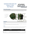
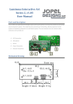
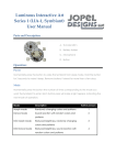
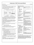
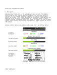
Automotive Computer
Peripheral Power Supply
Version 1, Rev. 1.03
User Manual
Brief:
The ACPPSv1 R1.03 is an
automotive specific Point of
Load (POL) aimed at USB
power applications. It offers
high power, accuracy,
reliability, low noise, and
durability. Safety features
include output short circuit, and
over temperature protection.
Specifications:
Input Voltage: 9-20V
Stand by Current: <5µA
Idle Current, No Load: <40mA
Remote Enable Signal: 5-20V
Auxiliary Output Current: 5A
Switching Frequency: 300 kHz
Operating temperature: 50˚C to -40˚C
Output Voltage: 5V+/- 2%
Output Current: 7.5A (Continuous)
10A (Peak, <1min)
Output Ripple: <35mV (30C)
<125mV (-40C)
System Block Diagram:
Connections and Indicators:
Top View
A.
B.
C.
D.
E.
F.
+5V Output
+5V Output
+5V Output
Ground
Ground
+12V Input
G.
H.
I.
J.
K.
L.
+12V Input
Remote Enable
Auxiliary Output
USB Enable
Status LED
Fuse (15A ATO)
Description of Connections:
Auxiliary Output:
The Auxiliary Output is connected to the 12V Input by a fuse and relay. When the
ACPPS is “Enabled” the relay closes and the 12V Input is routed to this pin. The
Auxiliary Output is not voltage regulated and should be limited to 5A to avoid damaging
the contacts inside the relay. This output can be used to control other POL devices, Amp
triggers, etc.
Remote Enable:
This pin turns the ACPPS on when a positive voltage is applied. This pin will trigger on
with as little as 5V or as much as 20V.
12V Input:
In the aftermarket automotive industry this connection is commonly referred to as a
“Constant Hot” or “Battery.” It should be connected to a 12V source that is not switched
by the ignition. Both 12V inputs are tied together internally. One connection can be used
as the input while the other is used to daisy-chain other devices requiring a constant 12V
source. Do not exceed 5A on a daisy chained device.
Ground:
This connection should be connected to a ground, chassis or negative power source. Both
grounds are connected directly together internally. This can be used to daisy-chain
multiple devices or provide the negative output to the load.
5V Output:
These 3 connections provide the 5V output from the ACPPS. All three connections are
tied together internally. The (combined) output current must be 7.5A or less for
continuous operation.
Status LED:
This Blue LED will illuminate solid when there is voltage at the 5V output. This
indicates the ACPPS is producing 5V. If this light is flashing, the load is too big, or the
ACPPS is in thermal protection mode.
USB Enable:
This connection monitors the power state of the host computer through a USB cable.
When the host computer turns on, power is supplied through the USB ports and the
ACPPS turns on. When power is removed from the USB ports the ACPPS will follow in
sync. The ACPPS is not an actual USB device. The computer will not communicate with
the ACPPS in any way and will not know it is attached.
Application Notes:
Do not use the Remote Enable and the USB Enable connections at the same time. It is
possible for these signals to conflict and cause improper operation.
When using the vehicles’ chassis as a ground point, keep wire lengths as short as possible
(ACPPS and Load). This helps keep the 5V output accurate and stable at the load.
To minimize voltage fluctuations when powering multiple loads use a separate 5V wire
for each load, starting from the ACPPS.
Remove the fuse while installing the ACPPS to avoid accidental power-ups and short
circuits.
Tighten any unused screws on the terminal block to keep them from falling out or
causing shorts circuits.
Reversing power wires can cause serious damage. Don’t do it. Be careful and mindful
while installing.
Typical Application, Computer Synchronized:
Troubleshooting:
Problem
Possible Causes/Solutions
No lights when remote signal is applied.
Bad connection(s). Remote, ground,
enable. Check that relay clicks with remote.
Short circuit at 5V output. Try with load
disconnected.
Over temperature protection active.
Short circuit on Aux output.
Input power is connected backwards.
One of your hubs is a “non-powered” hub
with a power input. Power is feeding from
the hub into the computer and back out to
the USB enable on the ACCPS.
Replace hub, or contact Jopel Designs for a
USB Isolator.
Bad connection (5V or GND), wire(s) too
small or long.
Blue Light Flashing
Fuses blows immediately upon insertion
ACCPS stays on after computer is powered
down or in standby.
Load Malfunctions
Mechanical Specifications:
Disclaimer of Liability
Jopel Designs shall not be held liable for any improper or incorrect use of the information
described and/or contained herein and assumes no responsibility for anyone's use of the
information. In no event shall Jopel Designs be liable for any direct, indirect, incidental,
special, exemplary, or consequential damages (including, but not limited to, procurement
or substitute goods or services; loss of use, data, or profits; or business interruption)
however caused and on any theory of liability, whether in contract, strict liability, or tort
(including negligence or otherwise) arising in any way out of the use of this product, even
if advised of the possibility of such damage.
This disclaimer of liability applies to any damages or injury, including but not limited to
those caused by any failure of performance, error, omission, interruption, deletion, defect,
delay in operation or transmission, computer virus, communication line failure, theft or
destruction or unauthorized access to, alteration of, whether for breach of contract
tortuous behavior, negligence or under any other cause of action.
User agrees to defend, indemnify, and hold harmless, Jopel Designs, its contributors, any
entity jointly created by them, their respective affiliates and their respective directors,
officers, employees, and agents from and against all claims and expenses, including
attorneys' fees, arising out of the use of any product or service by user or user's account.
Warranty Information
Jopel Designs warrants its products to be free from defects in material and workmanship
for 90 days, from date of purchase. If a product proves to be defective in material or
workmanship during the warranty period, Jopel Designs will, at its sole option, repair or
replace the product with a similar product. Replacement Product or parts may include
remanufactured or refurbished parts or components. The replacement unit will be covered
by the balance of the time remaining on the customer's original limited warranty.
Portland, Oregon. 2010
For Customer Support:
[email protected]
Author: Jesse Banks
Document Rev1.05