1
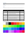
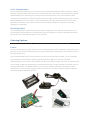
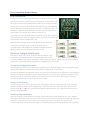
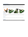
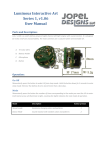
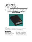
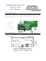
Luminous Interactive Art
Series 2, v1.05
User Manual
Parts and Description:
LIA-2 v1.05 is an eight channel LED light engine with sound reaction. It is known for small size and variety
of LED and power options. The model also has provisions for networking, allowing expansion of the
system to hundreds of channels in a multi-board system. The most common uses are costume attire,
stationary and wearable art.
A. LED Connection
B. Microphone
C. Button
D. Power Connection
E. Network Connection
Mechanical Drawing
Operation:
On-Off
Momentarily press the button to wake LIA from sleep mode. Hold the button down for 3 seconds to enter
sleep mode.
Mode
Momentarily press the button the number of times corresponding to the mode you want the LIA to enter.
Each button press will illuminate a light, counting the lights indicates the next mode of operation.
Mode
Description
Button presses
Morph
Custom color palette, random morph mode.
1
Dance
Custom color palette, dynamic sound processing.
2
Primary Color
Minimized color palette (red, orange, yellow, green, blue
3
Morph
purple and white), random morph mode.
Busy Morph
Custom color palette, ‘Choose from 3’ morph sub-mode
4
Dull Morph
Custom color palette, ‘Follow the leader’ morph sub-
5
mode.
Primary Color
Minimized color palette (red, orange, yellow, green, blue
Dance
purple and white), dynamic sound processing.
Twitchy Dance
Custom color palette, fast sound processing.
7
White mode
All lights full white, no morphing or changing
8
Default Color Palette
6
Color Customization
Color customization allows the user to control the color palette available for random selection. From an
ON state, hold the button (10 seconds) until all LED’s glow blue, then release. The available color palette
will be displayed in a repeating cycle, pausing several seconds on each color. Colors that have been
removed are not displayed. Pressing the button makes the lights go dark indicating the current color has
been disabled from the color palette. Color customization ends when the button is held until all LED’s
glow blue (5 seconds) or the sequence repeats 3 times without modification. The final color being
displayed is not disabled.
Resetting Colors
The full color palette is restored by holding the button longer when entering color customization. Five
seconds after the lights glow blue (customization) they will change to red (reset). Releasing the button
then enters color customization with all colors restored.
Ordering Options:
Depending on its final use the LIA-2 v1.05 can be configured in various ways when ordering.
Power:
LIA-2 can be powered by various power sources including batteries and wall adapters. Any power source
from 4.5-5V can be used. Ordering options for power include Mini-USB connector, wires, battery pack or
bare (finished by user).
Three standard battery cells in series produce 4.5V. Any size can be used; AA, AAA, C, or D. USB cables
from computers and cell phone chargers typically provide 5V. Both are easy and convenient.
Another elegant power source is the portable emergency cell phone charger sold online for $10-30. There
are a number of different manufacturers producing devices with a range of options. The battery may be
rechargeable lithium or standard alkaline, come in various capacities, possibly augmented by solar
panels and can come in many size/form/color combinations. A portable cell phone charger is typically
used with the Mini-USB option of LIA-2.
LED connections:
These are the possible LED connection options. LIA can be built with all
channels uniform in type or mix and match.
Direct
The LED’s can be mounted directly to the circuit board. You can also
order LED’s ‘on the side’ if the user wishes to complete assembly.
Wires
LIA-2 can be ordered with wires soldered to each channel. If installation
is going to be simple this is your lowest cost option for a fully
assembled unit. The LEDs can be omitted, mounted at the end of the
wires, or ready to be soldered by the user.
Connector
A small connector can be used allowing for easy disconnection of LIA and LEDs. This is the best option if
the final product will need to be serviced (cleaning, etc.) or the LED installation is complicated. The
connectors are fairly robust for their size, but care must still be taken as they are quite small.
Bare
LED connections can be left empty for soldering later. LED’s and wires can be ordered as separate pieces.
This option saves connector cost while still allowing for a complicated LED installation. With this option
the LEDs (with wire leads) can be installed in the final product and the electrical connection to the LIA
made in place. This requires some soldering know-how and a fine tip soldering iron.
Wires:
The length, size, color and flexibility of wire can be specified for each LED.
LEDs:
Many types of LEDs can be specified ranging in size and characteristics. The most common LED used is
the clear straw hat (small, bright, wide angle). Other types are flat, or focused or translucent. Nearly any
kind of RGB can be used.
Multi-board Systems:
Multi board systems (2-10) can be created upon request. To synchronize multiple boards, communication
wires are run between each LIA. There is a ‘master’ LIA and one or more ‘slaves’. The ‘master’ acts
identically to a ‘stand alone’ LIA in every way. In a multi board system the ‘master’ sets the color and
mode of all connected LIA’s, but each chooses patterns independently. They work together while
maintaining individuality. The network connections have the same ordering options as the LEDs (solder,
connector, bare).
Special Software:
The LIA software was developed in house with an emphasis on customization. Special modes, patterns,
sequences, colors and behaviors are all possible at minimal cost. Please contact us for a quote.
User Assembly Instructions:
LED Connections:
In the picture to the right is one LED output. It consists of one common
connection and three color outputs. All LED outputs are pinned out with
the same structure. Eight outputs are available, any can be left unused.
Care must be given to connect the LED’s correctly. Every 4-pin RGB LED
has an electrical connection for each color and a ‘common’ anode (+) or
cathode (-). Different styles of LED can be used, the only requirement is
that all LED’s must be the same polarity (common +/-).
The 3 color connections can be made in any way, but all LED’s need to be
connected the same way. All red light elements must be connected to the
same position across all LED outputs, etc.
Wires can be any length, but less than 10 feet is best. Each LED
consumes mere milliamps of current so the wires can be
incredibly small. A 40 gauge wire (smallest in the American wire
gauge system) can carry more than enough current.
Hardware Configuration Routine
This feature allows LIA-2 to be configured for LED polarity, color
connections, and output utilization. If an LED output has no LED
it can be disabled in this routine. Disabling an LED output turns off the output and excludes it in pattern
generation. An accurate output configuration is suggested for best results.
To enter the configuration routine:
Start with power removed. Hold the button and apply power. Hold the button until the lights glow white
(10 seconds). Release the button and the hardware configuration routine starts.
To abort the hardware configuration routine at any time remove power. If the sequence is not completed
(through verification) it will begin again automatically the next time power is applied. Automatic restart
is convenient when a mistake is made or a hardware problem is found. Once this routine is started it
must be completed before normal operation can resume.
Routine 1; LED Polarity
The first configuration routine determines the LED polarity. The LED’s will all glow the same, changing
between 4 different output signal configurations. Two steps will show a blend of colors, two will be a
primary color (R, G, or B). Two will be brighter and two will be dimmer. Press the button when the dim
primary color is displayed.
Routine 2; Output Utilization
This step configures which outputs are enabled. Each LED output will be tested one at a time, glowing
white. Press the button when you see an LED lit. Pressing the button will enable the output and make the
light dim in confirmation. If the output has no LED you will not see any light. The sequence will
automatically move to the next output after a 5 second delay. By not pressing the button the output will
be disabled. Do not press the button if there is no LED lit. LED hardware or harness malfunctions may
also cause an LED not to illuminate.
Routine 3; Color Configuration
The next part of the hardware configuration routine is color configuration. The device will now learn
which wires are connected to which LED colors. It assumes that all red LED’s use the same wire on every
output, and so on. All enabled outputs will begin cycling red, green and blue (in no particular order).
Press the button while red is being displayed, the lights will dim confirming the input. Now press the
button on green, and finally blue.
If the wiring is incorrect, different outputs will show different colors at the same time. Verify that all
outputs are showing the same color. Also verify that all intended outputs light up.
Routine 4; Final Verification
At this point the configuration is complete and all that’s left is verification. All enabled outputs will begin
morphing through a rainbow pattern. This diagnostic routine allows for color comparison of all enabled
outputs. All outputs will glow the same color at the same time and will fade thru red, orange, yellow,
green, blue, purple, and repeat. If any output is wrong (wired differently, damaged, shorted, open) the
colors will not display correctly. If the colors have not been programmed properly the displayed sequence
will be in a different order.
If everything looks correct, press the button to exit the hardware configuration routine. The hardware
configuration is saved and a marker set to disable the hardware configuration routine from running next
time the unit powers on.
Care Instructions:
Unplugging Connectors:
Use a small tool when unplugging any connector, pulling directly on the wires will damage the plug.
Small diagonal cutters work quite well for this purpose. The first 1mm of travel requires extra force
because of a restraint designed into the shape of the plug. Once the restraint is passed the plug removes
easily.
Cleaning:
LIA can be cleaned. Use high concentration (+70%) rubbing alcohol (isopropyl) on a q-tip or small paint
brush to clean the circuit board and connectors. Do not submerge the microphone in liquid. Allow LIA to
fully dry before use.
Storage:
When LIA is unused for more than a week remove the battery or power source and store separately.
Support:
For questions, repairs, software upgrades, and support contact: [email protected]