1
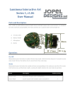
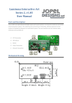
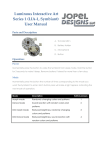
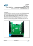
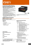
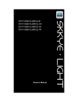
Luminous Interactive Art Series 3
(LIA-3) User Manual
LIA-3 is a stand alone multi channel light engine with sound interaction. It operates in two main modes;
morph and dance. At the core is a chaos engine designed to produce dynamic and beautiful displays of
light and color.
Morph mode produces a dynamic light show that is mesmerizing to watch and impossible to predict. It
consists of multiple sub-modes designed to create different effects. Some can appear static while others
change rapidly. The chaos engine is changing colors randomly from a user configurable color palette.
Every channel operates independently, choosing its own color and fade rate.
Dance mode generates a light display by sampling and analyzing local sounds using a built in omnidirectional microphone. Color and pattern changes occur at random intervals, similar to Morph mode,
but the brightness of each LED is controlled by a sound-to-light processor. The chaos engine is working
here too, it tweaks the sound-to-light processors’ variables so every interaction is unique.
The LIA-3 system is designed around a scalable control board for applications large and small. Each
control board has 8 color channels capable of driving 36 RGB LED’s per channel. Using low density
flexible LED strips that’s 4 feet. A total of 32 feet (8 x 4ft) can be powered by one control board.
Alternately, RGB spot and flood lights can also be used. High power models have three times the output
capability, or 108 LED’s per channel.
LIA -3 systems come in standard sizes ranging from 8-40 independent channels, and customized systems
have exceeded 150 channels. This design was created in house so customization is limitless. We can add
sensor inputs, create specialized modes, adapt for automotive and solar use, and build custom interfaces
and displays.
1
Parts:
8 Channel model pictured.
A. Power Plug
B. Power Switch
C. Mode Button
D. Microphone
E. LED Output
Normal Operation:
Power
The LIA-3 comes supplied with a standard computer power cord (C13 to NEMA-5) which is useful in the
US. The internal AC-DC power supply is designed to operate world wide. It has an operational range of
100-240V, 50-60Hz.
The Power Switch is the normal method for turning the unit ON and OFF.
2
Changing Mode
Quickly tap the Mode button the number of times corresponding to the mode you want the LIA-3 to
enter. Each press of the button will make a light glow white, indicating the next mode of operation.
Mode
Description
Button presses
Fully Random
Random color selection from customized palette and
Morph Mode
random morph sub-mode.
Fully Random
Sound reactive with random color selection from
Dance Mode
customized palette and random signal processing
1
2
variables.
Primary Color
Minimal color palette (red, orange, yellow, green, blue
Morph Mode
purple and white) and random morph sub-mode.
Extra Active
‘Choose from 3’ sub-mode and random color selection
Morph Mode
from customized palette.
Extra Dull
‘Follow the leader’ sub-mode, and random color selection
Morph Mode
from customized palette.
Primary Color
Sound mode, Minimal color palette (red, orange, yellow,
Dance Mode
green, blue purple and white) and random signal
3
4
5
6
processing variables.
Twitchy Dance
Sound mode, random color selection from customized
Mode
palette and fixed signal processing variables for fastest
7
response.
White mode
All lights full white, no morphing or changing
3
8
Colors
Available Colors
The default color palette
Customized Color Palette Programming
This function allows the user to limit which colors are available for most morph and dance modes. To
enter color programming mode hold the button until all LED’s glow blue, 15 seconds. Release the button
and color programming will begin.
All (only) enabled colors will be displayed in a repeating cycle. A color will be displayed for 5 seconds
providing an opportunity disable it. Pressing the button will disable the color in the customized color
palette. The light will dim confirming the button has been pressed, staying dark until it is released.
To end color programming mode hold the button until all the lights turn blue, 5 seconds. The final color
being displayed will not be removed. Alternately, color programming mode will automatically end when
the color cycle loops 3 times without modification.
Restoring Default Colors
Restoring a LIA-3 to default color settings is similar to entering programming mode, but the button is
held longer. About 5 seconds after the lights glow Blue to signal color programming mode they will glow
Red to signal the customized color palette has been restored to default. Releasing the Mode button will
enter color programming mode with all colors available.
4
Hardware Design
Preface
This section is intended to help the more adventurous user design and construct a custom installation
with a LIA-3 light engine. The following sections will describe the design requirements of the wire
harnesses, LED’s and how to configure the LIA-3 to properly use the custom hardware.
IDC Description
LIA-3 uses 0.050” Insulation Displacement Cable (IDC) to connect the controller to the lights. IDC is cost
effective, simple and easily configured. It also allows for multi directional and multi drop (output) wire
harnesses.
IDC Cable
Connectors attach to the cable without splicing or soldering. The housing is squeezed around the wire
while small pins pierce through the insulation and make a connection to each wire. Care must be given to
properly aligning the cable before crimping the connector. A small misalignment may cause wires to
short together or connections to be missed.
Uncrimped IDC Connector
IDC offers the ability to ’zip’ or split wires into separate groups with minimal effort. This is especially
useful when installing a LIA-3 system. The harness can be built on the bench as a generic harness cut to
5
the length of the longest run. During installation the harness is split apart to suite the needs of each
particular location. The harness starts as 1 wide cable and as each channel separates the harness gets
narrower.
IDC cable ‘Zipped’ to create separate wire groups.
Controller Side Harness Specifications
The controller side harness connection is made with a 40 pin connector (OMRON XG4M-4030-T or
equivalent). IDC connectors are polarized, meaning they only mate with receptacles in one orientation.
Pin 1 is generally designated by a Small triangle on one end.
IDC Connector with Pin 1 Highlight
LIA-3 light signals don’t start at pin 1, they start at pin 40 and work their way down. Every 4 wires is a
separate light channel. The highest numbered pin in a group is positive (+), the other 3 (A, B, C) are color
grounds.
6
All LED channels must be wired the in the same way. The positive (Anode) connection must be connected
to the LED positive. Color grounds can be configured with software but must be consistent across all
channels. The hardware configuration routine can learn which output drives witch color but only if all
light channels are wired the same. If Output A1 drives the Red LEDs in Channel 1, then Output Ax must
also control Red.
LIA-3 has 8 light channels that use 4 wires each, giving a total of 32 wires in use. The remaining 8 wires
(1-8) are unused and should remain unconnected (hint: fewer conductor IDC cable may be used to save
cable cost and waste.)
Controller side wire connections.
Wire/Pin descriptions.
Pin
Sig.
Pin
Sig.
Pin
Sig.
Pin
Sig.
Pin
Sig.
1
NA
5
NA
9
A8
13
A7
17
A6
2
NA
6
NA
10
B8
14
B7
18
B6
3
NA
7
NA
11
C8
15
C7
19
C6
4
NA
8
NA
12
+8
16
+7
20
+6
7
Wire/Pin descriptions. (cont.)
Pin
Sig.
Pin
Sig.
Pin
Sig.
Pin
Sig.
Pin
Sig.
21
A5
25
A4
29
A3
33
A2
37
A1
22
B5
26
B4
30
B3
34
B2
38
B1
23
C5
27
C4
31
C3
35
C2
39
C1
24
+5
28
+4
32
+3
36
+2
40
+1
If one or more channels are unused the wire can be left disconnected without harm. Do not let the wires
short-circuit together, this may cause damage. For custom installations it is advisable to leave portions of
the controller side connector empty to remove any chance of accidental shorts. If a harness has been
built with expansion in mind take care to isolate the unused wires from shorts.
LED Side Harness Specifications
The LED side harness connection is made with a 4 pin IDC connector (FCI 71600-104LF or equivalent). The
polarization of this connector is also important. The connector is too small to have an arrow marking pin
1, but it does have tabs protruding from one side to indicate correct orientation.
LED Side Wire Connections.
Care must be taken to properly orient the LED side connector in reference to the controller side
connector. Pin 1 of the LED connector is connected to the positive for that channel. If the connector is for
8
Channel 1, pin 40 from the controller connector goes to pin 1 of the LED connector. A felt maker helps
keep the positive wire located. Plugging your LED’s into this connector with improper orientation
*probably* will not damage them, but they will not work properly.
LIA-3 harness layout
The design of the harness can range from simple to complex. IDC cable provides flexibility and capability
to easily build harnesses for any situation. IDC gives the option for a connector to mount to the top or
bottom of the harness. It also allows for connectors to be added to the middle of a harness as easily as
the end.
A simple harness may have a cable cut 25 feet long, a controller connector attached to one end and 8
LED connectors pinched at the end. The harness is zipped apart to reach all the locations and the
remaining wire secured in bunches with zip ties.
A more complicated harness could have the 50 feet of cable, a controller connector mounted in the
middle and 16 LED connectors, 8 attached at each end. In this scenario each channel is running lights in 2
different locations. The lights connected at different locations will copy each other, fading together and
creating the same color light. Each channel can drive multiple LED sections as long as it is not
overloaded.
Led Hardware Description
Every LIA-3 has 8 light channels, each capable of driving an RGB light source. Each light channel consists
of 4 wires; A common anode (+), red (-), green (-), and blue (-). The simplest light source is Common
Anode 12V RGB LED strips. The LIA-3 system is designed with this light source in mind.
12V RGB LED strip.
LED strips vary, but most can be cut to 2” or 4” lengths as they are designed with repeating segments.
Each segment consists of 3 RGB LED’s (9 total LEDs) wired in series with a current limiting resistor. Each
channel can power 12 segments of LED strip or 36 RGB LED’s. The schematic below shows 4 segments or
12 RGB LEDs. High powered models can run 108 RGB LED’s per channel. Alternate LED light sources can
also be used (spot, flood light) but they should follow a similar design.
9
Schematic of 4 segments of flexible RGB LED strip.
LED Header
All LED’s in a system must be wired the same way. RGB strips offer a simple way to mount the header
and force uniformity. A piece of dual row 1/10” header strip can be soldered to the LED strip with the 2
center pads directly soldered to the header. The other two connections are made with small pieces of
wire bridging the gap between the header pins and the edge pads of the LED strip. The finishing touch is
a piece of heat shrink tube around the whole thing to avoid short circuits.
Breaking apart a dual row header.
LIA-3 standard LED to header mounting scheme.
10
An RGB LED strip ready to use
An RGB LED strip connected to a harness.
11
Hardware Configuration Routine
The LIA-3 can be configured depending on how many light channels are being used and how the red
green and blue lights are connected. If a channel is disabled the outputs are turned off and that channel
is not included in pattern generation. Proper channel configuration is suggested for best results.
To enter the configuration routine start with the unit powered off. Hold the Mode button and turn ON
the power switch. Hold the button until the lights glow white. Once the button is released the hardware
configuration routine starts.
The first configuration routine handles which channels are enabled. Each channel will be tested one at a
time. The channel being tested will light up white (all outputs on). Pressing the button when you see a
channel illuminated will enable the channel. The light will dim confirming the button has been pressed.
If the channel has no LED(s) you will not see any light. The sequence will automatically move to the next
channel after a 5 second delay. By not pressing the button the channel will be disabled. Do not press the
button if there are no LED’s lit. Led hardware or harness malfunction can also cause a light not to
illuminate.
The next part of the hardware configuration routine is color configuration. The device will now learn
which wires are connected to which LED colors. It assumes that all red LED’s use the same wire on every
channel, and so on. All enabled channels will begin cycling red, green and blue (in no particular order).
If the wiring is not correct then different channels will show different colors. Verify that all light channels
light up. Also verify that all channels are showing the same color. Press the mode button while red is
being displayed, then green, and finally blue. The lights will dim each time the button has been pressed
confirming the input.
All configuration is complete, the next step is color verification. All enabled channels will begin morphing
through a rainbow pattern. This is diagnostic routine allowing for color comparison of all enabled
channels. All channels will glow the same color at the same time. The sequence will fade thru red,
orange, yellow, green, blue, purple, and repeat. If any channel is wired differently (or damaged, shorted,
open) the colors will not display correctly.
If everything looks correct, press the Mode button to complete the hardware configuration routine. At
this point the hardware configuration is saved and a marker set to stop the hardware configuration
routine running next time the unit powers on.
12
To abort the hardware configuration routine at any time switch the unit OFF. If the sequence is not
completed the hardware configuration routine will begin again automatically the next time the unit is
turned ON. This is convenient when a mistake is made or a problem is found.
Disclaimer of Liability
Jopel Designs shall not be held liable for any improper or incorrect use of the information described
and/or contained herein and assumes no responsibility for anyone's use of the information. In no event
shall Jopel Designs be liable for any direct, indirect, incidental, special, exemplary, or consequential
damages (including, but not limited to, procurement or substitute goods or services; loss of use, data, or
profits; or business interruption) however caused and on any theory of liability, whether in contract, strict
liability, or tort (including negligence or otherwise) arising in any way out of the use of this product, even
if advised of the possibility of such damage.
This disclaimer of liability applies to any damages or injury, including but not limited to those caused by
any failure of performance, error, omission, interruption, deletion, defect, delay in operation or
transmission, computer virus, communication line failure, theft or destruction or unauthorized access to,
alteration of, whether for breach of contract, tortuous behavior, negligence or under any other cause of
action.
User agrees to defend, indemnify, and hold harmless, Jopel Designs, its contributors, any entity jointly
created by them, their respective affiliates and their respective directors, officers, employees, and agents
from and against all claims and expenses, including attorneys' fees, arising out of the use of any product
or service by user or user's account.
Warranty Information
Jopel Designs warrants its products to be free from defects in material and workmanship for 90 days,
from date of purchase. If a product proves to be defective in material or workmanship during the
warranty period, Jopel Designs will, at its sole option, repair or replace the product with a similar
product. Replacement Product or parts may include remanufactured or refurbished parts or components.
The replacement unit will be covered by the balance of the time remaining on the customer's original
limited warranty.
Support:
For questions, repairs, software upgrades, and support contact: [email protected]
13
Portland, Oregon. 2011
Author: Jesse Banks
Document Rev1.00
14