1
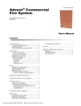
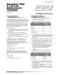
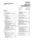
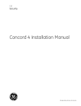
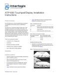
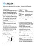
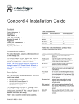
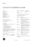
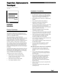
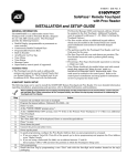
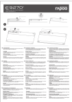
ITI Part No. 60-839
Document Number: 466-1759 Rev. B
August 2000
T e s t S y s te m
W e e k ly
p re s s b o th
2
3
S ile n t
P a g e r
4
5
6
F e a tu re s
S y s te m
M e n u
7
8
9
S ta tu s
L ig h ts
B y p a s s
0
#
C
p re s s b o th
D
A w a y
1
B
p re s s b o th
H o m e
O ff
N o D e la y
A
*
Installation Instructions
Product Summary
Table 1. Touchpad Power Usage
The Multilingual SuperBus 2000 2x16 LCD (liquid-crystal
display) Alphanumeric Touchpad lets you control all programming and operation of the International Concord security system.
Current (mA)
The 2-line, 16-character display provides messages to indicate the current status of the system. The touchpad includes
police, fire, and auxiliary panic buttons that can be activated
anytime. A built-in speaker provides alarm, status, and button-press sounds.
This touchpad can be quickly connected and disconnected
from the panel circuit board, as described later in this document. If you plan on installing systems with no alphanumeric touchpads, you may want to keep one of these
touchpads with you for programming.
Conditions
115
Maximum alarm current with the
buzzer sounding and the keypad
illuminated from a keypad press
90
Maximum alarm current with the
buzzer sounding or a keypad press,
but not both.
57
Typical operation
12
Standby current (no AC power)
Table 2. Maximum Touchpad Wire Lengths
Installation Guidelines
❑
❑
❑
Mount the touchpad in an environmentally controlled
area (4°C to 38°C or 40°F to 100°F).
When mounting the touchpad, allow at least 4¼ inches
on the left side for the Quick Guide slide-out card.
Do not exceed the maximum available power. See the
panel installation instructions for maximum available
power when using panel power for bus devices and
hardwire devices.
Important !
If separate power supplies are necessary to accomodate bus devices and hardwire devices, safety standards require that each power supply be prominently
marked with adequate instructions for removing all
power from the unit.
❑
❑
❑
❑
Wire Gauge
(Unshielded or
Shielded)
Max. Touchpad Wire Length
Between Touchpad and Panel
18
750 feet
22
300 feet
Tools and Equipment Needed
❑
❑
❑
❑
❑
4-conductor, 22- or 18-gauge wire
Screwdriver
#6 screws and anchors (included)
Panhead screws for gang box installation
Saw or utility knife for cutting wallboard
Table 1 describes the power used by the touchpad.
Table 2 describes the maximum wire lengths allowed
between the touchpad and the panel.
Up to 16 SuperBus 2000 devices can be connected to
and addressed by an International Concord panel.
Language and bus device address settings are automatic for International Concord systems.
Multilingual SuperBus® 2000 2x16 LCD Alphanumeric Touchpad
1
Installation
PRESS
MOUNTING
PLATE TAB
WALL MOUNTING HOLES (4)
R E M O V E S C R E W
(IF N E C E S S A R Y )
WIRE
ACCESS
AREA
9064A33.DS4
BREAK-AWAY TAMPER
MOUNTING HOLE
Figure 2. Marking the Mounting Holes
S W IN G M O U N T IN G
P L A T E A W A Y F R O M
T O U C H P A D C O V E R
9064a32.DSF
4.
Slide the card in the direction of the arrow
until it snaps into the position shown.
5.
Position the mounting plate in its normal mounting
position (tab at the bottom) and fold the card toward
you at all three scored lines. The “Zones” section
should be facing you and the folds should create a tab
to slide the card in and out.
6.
Align the mounting plate holes with the wall or gang
box screw holes and secure the back plate using the
screws provided.
Figure 1. Separating the Touchpad from the Mounting
Plate
Installation
The touchpad can be installed on a wall or in an electrical
gang box, either single- or dual-gang.
To comply with safety standards, the touchpad must be
secured to the building structure before operation.
Installing the Mounting Plate
1.
Separate the mounting plate from the touchpad by first
removing the screw, if necessary. Then press in the tab
at the bottom and swing the mounting plate away from
the touchpad cover (see Figure 1).
2.
For wall-mount installations, place the mounting plate
on the wall. Mark the wall at the break-away tamper
hole and the mounting holes (see Figure 2). Be sure to
leave a 4¼-inch clearance on the left side to allow for
the Quick Guide slide-out card. Insert anchors into the
wall at the marked locations where studs are not
present.
3.
Looking at the back side of the mounting plate, turn it
so the tab is on the left (see Figure 3) and position the
Quick Guide slide card into the slots on the back of the
mounting plate as shown. Make sure the card is
unfolded and the “Zones” section is facing you.
2
Note
Do not overtighten screws or the back plate may bind
and prevent the touchpad from mounting properly.
7.
For wall-mount installations, cut a hole in the wall in
the wire access area of the mounting plate to pull the
wiring cable through.
Multilingual SuperBus® 2000 2x16 LCD Alphanumeric Touchpad
Wiring
3.
Connect the 4-conductor cable wires to the +12V, A, B,
and GND terminals on the back of the touchpad.
4.
Connect the touchpad wiring to the panel terminals as
shown in Figure 4.
GND/BLACK
BUS B/WHITE
BUS A/GREEN
+12V/RED
1
+12V
RED
Z O N
0 1 _ E S
_
_
0 2 _ _ _ _ _ _
_
0 3 _ _ _ _ _
_
_
0 4 _ _ _ _ _ _
_
0 5 _ _ _ _ _ _
_
0 6 _ _ _ _ _ _
_
0 7 _ _ _ _ _ _
_
0 8 _ _ _ _ _ _
_ _ _ _ _
SWING CARD OVER IN
DIRECTION OF ARROW
UNTIL CARD SNAPS
INTO PLACE
2
3
A BUS B
GREEN WHITE
4
GND
BLACK
PANEL TERMINALS
Figure 4. Wiring the Touchpad to Panel Terminals
Attaching the Touchpad to the
Mounting Plate
Align the tab at the top of the touchpad with the slot on the
mounting plate and swing the touchpad down until you hear
the latch on the mounting plate click into place. Install the
screw into the bottom of the touchpad.
Power Up and Bus Communication
Z O
0 1 _
0 2 _
0 3 _
0 4 _
0 5 _
0 6 _
0 7 _
0 8 _
N E
_ _ _
_ _ _
_ _ _
_ _ _
_ _ _
_ _ _
_ _ _
_ _ _
S
_ _ _
_ _ _
_ _ _
_ _ _
_ _ _
_ _ _
_ _ _
_ _ _
9064A34.DSF
Figure 3. Inserting the Quick Guide Slide Card into the
Mounting Plate
Wiring
After making all wiring connections from the touchpad to
the panel, you are ready to power up the panel and verify
correct communication between the touchpad and the panel.
Upon power up, the panel scans the bus for connected
devices, assigns a unit number to each bus device, and automatically learns the device ID number of each bus device.
To power up the panel and verify bus
communication:
1.
Verify that all wiring between the panel and touchpad is
correct.
2.
Connect the panel battery and restore AC power.
Alphanumeric touchpads briefly show SCANNING
BUS DEVICES, then display date and time.
Wiring consists of connecting the touchpad to the panel terminals.
Note
Wiring the Touchpad to International
Concord Panels
1.
Remove power from the panel and disconnect the
backup battery.
2.
Run a 4-conductor, 18- to 22-gauge wire from the panel
to the touchpad location (see Table 2).
Multilingual SuperBus® 2000 2x16 LCD Alphanumeric Touchpad
Steps 3 through 10 are optional.
3.
At the touchpad, enter program mode by pressing 8 +
installer/dealer code (default = 54321) + 0 + 0.
The touchpad should display SYSTEM PROGRAMMING.
4.
Press ƒ and the display shows SECURITY.
5.
Press A or B until the display shows ACCESSORY
MODULES, then press ƒ. The display should read
BUS DEVICES.
3
Testing
6.
Press ƒ. The display shows the lowest device address
and its ID. The following example shows what the
International Concord device address display may look
like:
UNIT - ID
0—02110185*
*The 8-digit SuperBus ID number is also located on a
label on back of the touchpad.
7.
Press A or B to cycle through all bus device addresses
until the touchpad appears.
8.
After verifying the touchpad device ID, press ‚ repeatedly until the display shows SYSTEM PROGRAMMING.
To connect a programming touchpad to an
International Concord panel:
1.
With the panel powered up, connect the cable onto a
panel Programming Touchpad Header (see Figure 5).
Note
If you connect the touchpad before the panel is powered up, the panel will add the touchpad to system
memory when power is applied. You will then need to
delete the touchpad from the panel memory before
you disconnect it to prevent a bus failure. See the
panel installation instructions for more information.
2.
Enable the programming (or service) touchpad by
pressing 8 + installer or dealer code + 0 + 2. While
the service touchpad is active, the touchpad will show a
flashing star and trouble beeps will sound (5 beeps per
minute).
Programming
3.
Enter programming mode by pressing 8 + installer or
dealer code + 0 + 0 and program the panel using the
panel installation instructions.
To progam options for the newly installed touchpad (such
as key beeps and display brightness) see the panel installation instructions.
4.
When programming is completed, simply disconnect
the programming touchpad.
9.
Press A or B until the display shows EXIT PROGRAMMING READY, then press ƒ. The touchpad
should show the date and time display.
Connecting the Touchpad for System
Programming Only
For system programming of installations that don’t include
an alphanumeric touchpad as a permanent part of the system, you can temporarily connect the touchpad to the panel.
To do this, you must first connect a Programming Touchpad
Cable (60-858) to the touchpad wires (see the installation
instructions included with the cable). Then connect the
cable to the Programming Touchpad Header on the panel.
Note
Be aware that the “partition jumping” feature is not
available to users when a temporary programming
touchpad is connected to the International Concord
panel Programming Touchpad Header.
T e s t S y s te m
O ff
W e e k ly
A
p re s s b o th
p re s s b o th
If you need to use partition jumping while the touchpad is connected to the Programming Touchpad
Header, you must add the touchpad to panel memory
as if it were a permanent touchpad. To do this, you
must remove power from the panel before connecting
the Programming Touchpad Cable to the panel. Then
use the procedure described earlier in this manual
under “Power Up and Bus Communication.”
D
A w a y
2
3
S ile n t
P a g e r
4
5
6
F e a tu re s
S y s te m
M e n u
7
8
9
S ta tu s
L ig h ts
B y p a s s
0
#
C
p re s s b o th
H o m e
1
N o D e la y
B
*
PROGRAMMING
TOUCHPAD
CABLE (60-858)
9064A37.DSF
Figure 5. Where to Connect a Programming Touchpad
Testing
CAUTION
Contact the central monitoring station before activating
alarms, to avoid dispatching local police and fire
departments.
Test the touchpad by arming/disarming the system, activating the touchpad panics, bypassing sensors, and by turning
chime and lights on/off to verify correct operation. Refer to
the panel User’s Manual for complete system operating
instructions.
4
Multilingual SuperBus® 2000 2x16 LCD Alphanumeric Touchpad
Adjusting Display Contrast
Adjusting Display Contrast
Specifications
The touchpad display contrast can be adjusted for easier
viewing to help compensate for lighting conditions in the
touchpad location. The contrast adjustment lightens or darkens the text.
Compatibility:
To adjust display contrast:
Temperature Range: 40°F (4°C) to 100°F (38°C)
1.
Enter configuration mode by pressing the D and 6
buttons together for at least two seconds. The display
shows DA nnn.
2.
Press and release the 1 and 2 buttons together repeatedly, until the desired contrast level is displayed.
3.
Press ‚ and the display briefly shows DONE, then
shows the time and date.
International Concord
Power Requirements: 12 VDC nominal (8 - 15.4 VDC),
115 mA (maximum), see Table 1.
Maximum Humidity: 70% relative, noncondensing
Dimensions:
5” (127 mm) x 4.5”(114 mm) x 1”
(25 mm)
Notices
This Intruder Alarm System Accessory (Security Grade 2, Environmental
Class II) has been manufactured to comply with the following European
directives:
Troubleshooting
[i] EMC Directive 89/336/EEC amending directive 92/31/EEC & 93/68 EEC as per
Table 3 describes what to do if the touchpad does not operate correctly.
EN 50081: 1992
EN 50130-04: 1995
[ii] Low Voltage Directive (Safety) 73/23/EEC as per
EN 60950: 1997-A11
Table 3: Troubleshooting
Problem
Changes or modifications not expressly approved by Interactive Technologies, Inc.
can void the user’s authority to operate the equipment.
Action/Solution
Touchpad doesn’t power 1.
up (no display and no
beeps when buttons are
pressed).
2.
Check for correct wiring connections at touchpad and panel
terminals.
Make sure panel battery is
connected correctly and that
AC power is present.
Touchpad display
Check the touchpad display
appears blank, but beeps contrast setting.
sound when buttons are
pressed.
Touchpad display shows
a flashing *, indicating a
trouble condition and
system doesn’t respond
to commands from
touchpad.
Check for correct bus wiring
connections (green and white
wires) at touchpad and panel
terminals.
©2000 Interactive Technologies, Inc., an Interlogix™ company.
Interlogix is a trademark of Interlogix, Inc. ITI and SuperBus are registered
trademarks of Interactive Technologies, Inc. Concord and SnapCard are
trademarks of Interactive Technologies, Inc.
Interactive Technologies, Inc.
2266 Second Street North
North Saint Paul, MN, USA 55109-2900
T: 651/777-2690
F: 651/779-4890
1-800-777-1415
Security
Automation
Fire Protection
Access Control
Multilingual SuperBus® 2000 2x16 LCD Alphanumeric Touchpad
www.ititechnologies.com
5