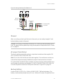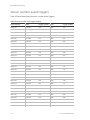
1
GE
Security
Concord 4 Installation Manual
P/N 466-2182 • REV G • ISS 12JUL10
Copyright
© 2010 GE Security, Inc.
This document may not be copied in whole or in part or otherwise reproduced without prior
written consent from GE Security, Inc., except where specifically permitted under US and
international copyright law.
Disclaimer
The information in this document is subject to change without notice. GE Security, Inc.
(“GE Security”) assumes no responsibility for inaccuracies or omissions and specifically disclaims
any liabilities, losses, or risks, personal or otherwise, incurred as a consequence, directly or
indirectly, of the use or application of any of the contents of this document. For the latest
documentation, contact your local supplier or visit us online at www.gesecurity.com.
This publication may contain examples of screen captures and reports used in daily operations.
Examples may include fictitious names of individuals and companies. Any similarity to names
and addresses of actual businesses or persons is entirely coincidental.
Trademarks and patents
GE and the GE monogram are trademarks of General Electric Company.
Other trade names used in this document may be trademarks or registered trademarks of the
manufacturers or vendors of the respective products.
Intended use
Contact information
Use this product only for the purpose it was designed for; refer to the data sheet and user
documentation for details. For the latest product information, contact your local supplier or visit
us online at www.gesecurity.com.
For contact information see out Web site: www.gesecurity.com
Content
Important information iii
Chapter 1 Introduction 1
Planning the installation 2
SuperBus 2000 bus devices 3
Chapter 2 Installation 5
Installation overview 6
Mounting the panel 10
Intrusion detection devices 14
Smoke detectors 14
Speakers and sirens 17
SuperBus 2000 touchpads 21
SuperBus 2000 modules 21
Phones 27
Power 29
Chapter 3 Programming 31
Overview 32
Quick programming mode 34
Tier 1 programming menus 35
Tier 2 programming menus 37
Security menu 43
Phones menu 48
Phone options menu 52
Timers menu 55
Light control menu 57
Touchpad options menu 58
Reporting menu 59
Siren options menu 64
Sensors menu 65
Audio verification menu 69
Accessory modules menu 71
Onboard options menu 75
Macro keys menu 78
User programming mode 79
Downloader programming 89
Chapter 4 Testing and troubleshooting 91
Testing the system 92
Concord 4 Installation Manual
i
Troubleshooting 101
Appendix A System planning sheets 111
Customer information 112
Wireless devices 112
Hardware devices 113
Zone and sensor assignments 115
System settings index and record 118
Appendix B Reference tables 123
Sensor group characteristics 124
Sensor text 128
System event triggers 130
Sensor group event triggers 131
Sensor number event triggers 132
System feature event triggers 135
Response characteristics 136
Response numbers 136
Specifications 138
ii
Concord 4 Installation Manual
Important information
Intended use
Use this product only for the purpose it was designed for; refer to the data sheet and
user documentation for details. For the latest product information, contact your local
supplier or visit us online at www.gesecurity.com.
Changes or modifications not expressly approved by GE Security can void the user’s
authority to operate the equipment.
About this manual
This manual provides information for planning, installing, programming, and testing
this security system. Planning sheets are included for you to record hardware layout
and software programming settings.
Use this manual for the following panels:
600-1021-95R
Concord 4 RF
600-1022-95R
Concord Express V4
600-1040
Concord Commercial V4
600-1042
Concord Hybrid
When necessary, this manual refers you to other documentation with compatible
peripherals.
The Concord 4 User Manual (P/N 466-2183) contains user worksheets that you should
fill out during the installation and programming of the system. For multiple-partition
systems, we suggest a user manual for each partition.
Read these instructions and all related documentation entirely before installing or
operating this product.
Note: A qualified service person, complying with all applicable codes, should perform
all required hardware installation.
Concord 4 Installation Manual
iii
iv
Concord 4 Installation Manual
Chapter 1
Introduction
Summary
This chapter provides information to help you plan your Concord 4 panel and system
installation.
Content
Planning the installation 2
Standard panel 2
SuperBus 2000 bus devices 3
Concord 4 Installation Manual
1
Chapter 1: Introduction
Planning the installation
This section describes system capabilities to help you get familiar with the system.
Appendix A “System planning sheets” on page 111 provides planning sheets that let
you record the hardware and programming configuration of the system. Fill in all
necessary information ahead of time to help prepare for system installation.
Standard panel
Table 1 below shows the standard panel capabilities.
Table 1: Panel capabilities
Capabilities
Concord Express v4
Concord 4/Concord Commercial v4
Zones
32
96
Partitions
2
6
Bus devices
16
16
User codes
16
230
Table 2 describes the basic panel (out-of-box) hardware capabilities for all panels.
Table 2: Basic panel hardware capabilities
Power
Input for an AC step-down, plug-in style transformer.
Auxiliary power output
Output that supplies 9 to 14 VDC with up to 1 amp for bus devices and
hardwired detectors, such as smoke and motion detectors.
Bus A and B
Input and output that provides communication between bus devices
and the panel.
Siren driver
Output that can drive an 8-ohm load and provides intrusion and fire
alarm sounds for partition 1 (15 watts maximum).
Two onboard outputs
Can be used to activate other signaling devices based on system
events.
Out 1 is a 9 to 14 VDC source output, limited to 1.0 amp max.
Out 2 is an open-collector output, rated up to 14 VDC, 300 mA max
Microphone input
Input used for 2-way audio when used in conjunction with the
Interrogator 200 audio verification module.
Eight supervised hardwired
zones
Inputs for various hardwired detectors. Zone 8 can be set up in
programming to accept two-wire smoke detectors. It sources 9 to 14
VDC, 90mA max.
Built-in RF receiver
Allows use of up to 96 (Concord 4) or 32 (Concord Express v4) 319.5
MHz. crystal and/or SAW learn mode wireless sensors and touchpads.
Phone line connection
Allows panel to communicate with central monitoring station and/or
pagers.
2
Concord 4 Installation Manual
Chapter 1: Introduction
SuperBus 2000 bus devices
The following components can be used with the Concord 4 panel:
Table 3: SuperBus devices
Touchpads
Use the following touchpads for installer/user programming and
system operation.
•
•
•
•
•
•
SuperBus 2000 2x16 LCD touchpad
SuperBus 2000 2x20 LCD touchpad
SuperBus 2000 2x20 VFD touchpad
SuperBus 2000 ATP 1000 touchpad
SuperBus 2000 ATP 2100 touchpad
SuperBus 2000 ATP 2600 touchpad
Use the following touchpads for installer quick programming,
system operation and user programming:
•
•
SuperBus 2000 fixed display touchpad
SuperBus 2000 FTP 1000 touchpad
SuperBus 2000 RF transceiver
Use the transceiver to receive signals from sensors and touchpad
that may be on the fringe of panel reception. The transceiver is
compatible with all 319.5 MHz crystal and SAW learn mode
wireless sensors and touchpads.
Power line carrier transformer
Allows the use of X10 powerhouse lamp modules for light control
and light activation during alarms.
SuperBus 2000 voice only
module
Provides an output for a speaker that sounds system status and
alarm voice messages.
SuperBus 2000 phone
interface/voice module
Allows system access and control using touchtone telephones,
onsite or offsite. The module includes an output for a speaker
that sounds system status and alarm voice messages
SnapCards
The following SnapCards expand the system as described:
8Z input Snapcard: Provides eight additional hardwired zone
inputs, of which two are dedicated for using two-wire smoke
detectors.
4 output SnapCard: Provides four form C relay outputs that can
be set up to activate other signaling devices, based on system
events, schedules, or direct control.
4Z input/output combo SnapCard: Provides three hardwired zone
inputs, one two-wire smoke detector loop, and two outputs that
can be set up to activate other signaling devices, based on
system events, schedules, or direct control.
SuperBus 2000 8Z input module
(HIM)
Provides eight additional hardwire zone inputs.
SuperBus 2000 four-relay output
module (HOM)
Provides four form C relay outputs that can be set up to activate
other signaling devices, based on system events.
Concord 4 Installation Manual
3
Chapter 1: Introduction
Interrogator 200 audio
verification module
Allows central station operators to listen in and talk to occupants
on the premises to verify the emergency when an alarm report is
received.
SuperBus 2000 energy saver
module (ESM)
Provides a money-saving and convenient way to monitor and
control temperatures. The ESM uses low- and high-temperature
limits to save energy by overriding the existing HVAC thermostat.
SuperBus 2000 automation
module
Provides a connection to a compatible home automation device.
SuperBus 2000 wireless cellular
gateway
Allows users to control and monitor the status of their system
from the alarm.com internet website.
SuperBus 2000 2-amp power
supply
Provides an additional 12 VDC, 2 amps for powering system
devices and is supervised via the panel data bus.
4
Concord 4 Installation Manual
Chapter 2
Installation
Summary
This chapter provides information on locating and installing the panel and system
components.
Content
Installation overview 6
Mounting the panel 10
Intrusion detection devices 14
Smoke detectors 14
Speakers and sirens 17
SuperBus 2000 touchpads 21
SuperBus 2000 modules 21
Phones 27
Power 29
Concord 4 Installation Manual
5
Chapter 2: Installation
Installation overview
Before starting the installation, plan your system layout and programming using the
worksheets provided in Appendix A “System planning sheets” on page 111.
Note: Class 2, Class 3, and power-limited fire alarm circuits must be installed using
FPL, FPLR, FPLP, or substitute cable permitted by the National Electrical Code
ANSI/NFPA 70 or Class 2, Class 3, and power-limited fire alarm circuit conductors
must be installed as Class 1 or higher circuits.
Note: Class 2, Class 3, and power-limited burglar alarm circuits must be installed
using CL2, CL2R, CL2P, or substituting cable permitted by ANSI/NFPA 70. Wire that
extends beyond the cable jacket must be separated from all other conductors by a
minimum of 0.25 in. or by a nonconductive barrier.
Use the following installation guidelines:
•
Centrally locate the panel with relation to detection devices whenever possible, to
help reduce wire run lengths and labor.
•
Locate the panel where the temperature will not exceed 120°F (49°C) or fall below
32°F (0°C).
•
Avoid running wires parallel with electrical wiring or fixtures such as fluorescent
lighting, to prevent wire runs from picking up electrical noise.
•
Mount the panel at a comfortable working height (about 45 to 55 in. from the floor
to the bottom of the panel, as shown in Figure 1 on page 7).
•
Leave space to the left and right of the panel for wiring, phone jack, and mounting
optional modules. Allow at least 9 in. (23 cm) above the panel cabinet for
antennas. Allow at least 24 in. (62 cm) in front of the panel to open the panel door.
6
Concord 4 Installation Manual
Chapter 2: Installation
Figure 1: Panel and component locations on a wall
19.25 in.
(48.9 cm)
23 in.
(58.5 cm)
45 to 55 in.
Phone jack and
optional module
mounting area
(114 to 140 cm)
Panel
9 in.
(23 cm)
Antenna area
7.25 in.
(18.4 cm)
14 in.
(35.5 cm)
12 in.
(30.5 cm)
Leave at least 24 in. (62 cm) in front of the panel
to allow the user to open the cabinet door and
access the panel components.
Floor
Total system power and wire length guidelines
The panel can supply up to 1 amp (1,000 mA) in full load alarm condition for system
devices connected to panel terminals 4 (+12V), 7 and 8 (speaker terminals), 9 (OUT1),
11 (+12V), 24 (2W SMK ZONE 8), and SnapCard terminals.
For 24-hour backup, the total standby current draw for all devices connected to
panel terminals 4 (+12V), 9 (OUT1), 11 (+12V), 24 (if configured for 2-wire smoke loop),
and SnapCard terminals is limited to 90 mA (during normal standby condition) using a
4.5 or 5.0 Ah battery, or 190 mA (during normal standby condition) using a 7.0 Ah
battery.
The total system wire length allowed can vary depending on devices powered by the
panel, the wire length between devices and the panel, and the combined wire length
of all devices.
Table 4 on page 8 describes the maximum wire length allowed between compatible
devices and the panel, and the minimum and maximum current draw of each device.
Concord 4 Installation Manual
7
Chapter 2: Installation
Table 4: Wire length requirements
Device
Max. wire
Standby mA
length to panel draw
Alarm mA draw
SuperBus 2000 2x16 LCD alphanumeric
touchpad
22 ga.: 300 ft.
18 ga.: 750 ft.
15 mA
90 mA
SuperBus 2000 ATP 1000 alphanumeric
touchpad
22 ga.: 300 ft.
18 ga.: 750 ft.
12 mA
110 mA
SuperBus 2000 ATP 2100 alphanumeric
touchpad
22 ga.: 300 ft.
18 ga.: 750 ft.
30 mA
165 mA
SuperBus 2000 ATP 2600 alphanumeric
touchpad
22 ga.: 300 ft.
18 ga.: 750 ft.
30 mA
165 mA
SuperBus 2000 fixed display touchpad
22 ga.: 300 ft.
18 ga.: 700 ft.
11 mA
65 mA
SuperBus 2000 FTP 1000 fixed display touchpad 22 ga.: 300 ft.
18 ga.: 700 ft.
12 mA
75 mA
SuperBus 2000 RF transceiver
22 ga.: 1,000 ft. 45 mA
18 ga.: 2,500 ft.
55 mA
SuperBus 2000 phone interface/voice module
22 ga.: 40 ft.
18 ga.: 120 ft.
25 mA
600 mA
SuperBus 2000 voice-only module
22 ga.: 40 ft.
18 ga.: 120 ft.
20 mA
300 mA (jumper)
SuperBus 2000 2 amp power supply
600 mA (no
jumper)
No load
No load
4 input/2 output SnapCard
N/A
20 mA
185 mA*
8Z hardwired zone expander SnapCard
N/A
38 mA
230 mA*
4 output SnapCard
N/A
1 mA
130 mA*
SuperBus 2000 8Z input module
22 ga.: 1,800 ft. 18 mA
18 ga.: 4,000 ft.
35 mA
SuperBus 2000 4-relay output module
22 ga.: 350 ft.
18 ga.: 900 ft.
180 mA
SuperBus 2000 energy saver module
22 ga.: 1,600 ft. 20 mA
18 ga.: 4,000 ft.
20 mA
SuperBus 2000 automation module
22 ga.: 1,500 ft. 30 mA
18 ga.: 4,000 ft.
35 mA
SuperBus 2000 wireless cellular gateway
22 ga.: 40 ft.
18 ga.: 90 ft.
1600 mA
Interrogator 200
22 ga.: 3,200 ft. 10 mA
18 ga.: 4,500 ft.
10 mA
Interrogator AVM
22 ga.: 110 ft.
18 ga.: 260 ft.
300 mA
8
12 mA
65 mA
45 mA
Concord 4 Installation Manual
Chapter 2: Installation
Device
Max. wire
Standby mA
length to panel draw
Alarm mA draw
Two-wire smoke detectors (ESL 429AT, 429C,
429CT, 521B, 521BXT, 521NCSXT
22 ga.: 330 ft.
18 ga.: 330 ft.
70 µA
60 mA
120 µA
80 mA
Two-wire smoke detectors (system sensor 2400, 22 ga.: 330 ft.
2400TH)
18 ga.: 330 ft.
Hardwired interior siren (13-949)
22 ga.: 750 ft. 0 mA
18 ga.: 1,500 ft.
85 mA
Piezo dynamic exterior siren (13-950)
22 ga.: 750 ft. 0 mA
18 ga.: 1,500 ft.
150 mA
Speaker siren (60-528 or 13-060)
18 ga.: 100 ft.
500 mA
0 mA
*Maximum current draw for the SnapCards does not include the load which may be applied to their
auxiliary DC supply.
Table 5 below describes the total system wire lengths allowed for all SuperBus 2000
devices when installing systems using unshielded or shielded cable. After determining
panel location, run all necessary wires to that location using the information in
Table 6 below.
Table 5: Wire lengths
Wire type
Total system wire
18-gauge, unshielded
18-gauge, shielded
4,000 ft.
3,000 ft.
22-gauge, unshielded
22-gauge, shielded
4,000 ft.
3,000 ft.
Table 6: Device wire requirements
Device
Wire requirements
AC power transformer
2-conductor, 18-gauge, 25 ft. max.
Earth ground
Single conductor, 16-gauge solid, 25 ft. max.
Telephone (RJ-31X)
4-conductor
Detection devices
2- or 4-conductor, 22-gauge, 1,000 ft. max.
2- or 4-conductor, 18-gauge, 2,500 ft. max.
(based on 30 ohms max. loop resistance including
device)
Speakers
2-conductor, 18-gauge, 100 ft. max.
SuperBus 2000 devices
4-conductor, 22- or 18-gauge
Interrogator 200 AVM power and microphone
4-conductor, 22-gauge, shielded
2-wire smoke detectors
2-conductor, 22-gauge, 330 ft. max.
2-conductor, 18-gauge, 830 ft. max.
Concord 4 Installation Manual
9
Chapter 2: Installation
Mounting the panel
Mount the panel to the wall or wall studs.
Caution: Make sure you are free of static electricity whenever you work on the panel
with the cover open. To discharge any static, first touch the metal panel chassis, and
then stay in contact with the chassis when touching the circuit board. We
recommend using a grounding strap.
To mount the panel:
1. Remove the panel door and remove the necessary wiring knockouts. Be careful
not to damage the circuit board.
2. Feed all wires through wiring knockouts and place the panel in position against
the wall.
3. Level the panel and mark the top and bottom mounting holes (see Figure 2
below).
4. Install anchors where studs are not present.
5. Partially insert screws into the two top mounting hole locations, then hang the
panel on the two screws.
6. Recheck for level, insert the two lower screws, and tighten all four mounting
screws.
Figure 2: Panel components and mounting holes
Antennas
Mounting hole
Backup battery terminals
Programming
touchpad header
Mounting hole
10
Mounting hole
Snapcard connector
Processor
Terminal strip
Mounting hole
Concord 4 Installation Manual
Chapter 2: Installation
Grounding the panel
For maximum protection from lightning strikes and transients, connect the enclosure
to earth ground as shown in Figure 3 below. Use 16-gauge, solid copper wire from an
earth grounded cold water pipe clamp to the enclosure.
Figure 3: Grounding the panel
Grounding wire
Grounding clamp
Water pipe
Note: For best results, we recommend that you crimp a spade lug on the wire end at
the panel and secure the lug to the enclosure.
Antenna shrouds
Install a plastic antenna shroud (included with panel) over each antenna and snap
them into the holes on the top of the enclosure (skip this step for hybrid and
commercial systems).
Concord 4 Installation Manual
11
Chapter 2: Installation
Optional SnapCards
Use the SnapCard header on the right side of the panel (Figure 4 below) to install an
optional SnapCard. Install the SnapCard onto the panel SnapCard header and secure
it in place with two screws, included with the SnapCard. To connect all necessary
input/output wiring, refer to the SnapCard documentation.
Figure 4: Installing a SnapCard
Mounting hole
Snapcard connector
Snapcard
Mounting hole
12
Concord 4 Installation Manual
Chapter 2: Installation
Panel terminals
Figure 5 below shows an overview of panel terminals. The following sections provide
details on how to connect devices to the panel.
Figure 5: Panel terminals
16.5 VAC
1
2
GND
+12V
A
B
3
4
5
6
SPKR SPKR
7
8
OUT1 OUT2 +12V
9
10
11
MIC
12
GND ZONE1 ZONE2 GND ZONE3 ZONE4 GND ZONE5 ZONE6 GND ZONE7 ZONE8 GRN
13
14
15
16
17
18
19
20
21
22
23
24
25
BRN
GRY
RED
26
27
28
GRY
BRN
(-) (+)
_
+
NC COM
GRN
RED
BUS A - Green
+12V - Red
GND - Black
BUS B - White or Yellow
(-) (+)
TIP
(+)
RING
(-)
SW SW GND #1 #2
Zones
The panel comes with factory programmed onboard hardwired zones. Install 2 kohm,
end-of-line (EOL) resistors on all unused factory programmed onboard hardwired
zones. If you don’t want to install EOL resistors, delete any unused zones from
memory.
Zone inputs 1 through 8 are supervised using the included 2-kohm, end-of-line
resistors at the last device on each circuit. All eight zones accept either normally open
(NO) or normally closed (NC) detection devices.
Concord 4 Installation Manual
13
Chapter 2: Installation
Intrusion detection devices
Figure 6 below shows the typical wiring for NC and NO door/window intrusion
detection and the typical wiring for a PIR motion detector. The minimum available
panel voltage for hardwired PIR motion detectors is 8.5 VDC.
Figure 6: Connecting intrusion detection and motion detector circuits
GND
ZONE1 ZONE2
GND
ZONE3
+12V
GND
ZONE5
Panel terminals
Normally closed
(NC) contacts
in series
Normally open
(NO) contacts
in series
Motion
detector
NC COM
2 kohm resistor
2 kohm resistor
Smoke detectors
You can connect two-wire and four-wire smoke detectors to the system.
Two-wire smoke detectors
Zone input 8 can be set up (in program mode) to accept the following 12 VDC, twowire smoke detectors:
ESL models 429AT, 429C, 429CT, 521B, 521BXT, 521NCSXT (models 521B and
521BXT require the following dip switch settings: 1-on, 2-off)
Caution: Use only the two-wire smoke detector models listed. Alarm signals from
other detectors may not process correctly if the panel loses AC power and is
operating only from the backup battery.
When set up for two-wire smoke detectors, zone 8 can handle up to 20 smoke
detectors (all of the same model, as listed above) with 120 uA maximum idle current
per detector. Maximum total loop current allowed in an alarm condition is 90 mA.
Connect one or more, two-wire smoke detectors to the panel as shown in Figure 7 on
page 15.
14
Concord 4 Installation Manual
Chapter 2: Installation
Note: When using two-wire smoke detectors on zone 8, the two-wire smoke setting
(in program mode) must be turned on before entering the learn sensors menu.
Figure 7: Connecting two- and four-wire smoke detectors
GND ZONE 7 ZONE 8
GND ZONE 7 ZONE 8
Panel terminals
Two-wire smoke
detectors
Four-wire smoke
detectors
Note: The two-wire smoke setting (in program mode) must be on when using fourwire smoke detectors as shown in Figure 7 above. See “Onboard options - inputs
settings” on page 75 for complete details.
If two-wire smoke detectors with built-in sounders are used (521INCSXT), a polarity
reversal relay (model 405-03) may be used to activate the sounders on all smoke
detectors during a fire alarm (see Figure 8 on page 16). An output must be used to
activate the polarity reversal relay. This output must be configured for fire alarm
trigger, and siren tracking response (001-11).
Note: Onboard outputs 1 or 2, SnapCard outputs, or output module outputs may be
used to activate the polarity reversal relay.
Maximum alarm current that the panel can source to all external devices is limited to
1 amp. Be sure to include the alarm current for all sounder smoke detectors in the
alarm current calculation.
Concord 4 Installation Manual
15
Chapter 2: Installation
Figure 8: Polarity reversal module
OUT 2
+12V
GND
2W-SMK
ZONE 8
Polarity reversal
module (part # 405-03)
521NCSXT
521NCSXT
Four-wire smoke detectors
Terminal 24 provides power to four-wire smoke detectors that latch and remain in
the alarm state until power turns off, then restores to the detector. The panel
provides this power interruption from terminal 24 (2W SMK ZONE 8) only when the
two-wire smoke option is on.
Note: The two-wire smoke feature must be on for smoke detectors to reset after
canceling a fire alarm.
Table 7 below describes the minimum available panel power. Use only four-wire
smoke detectors that operate at these power limits. Connect up to five smoke
detectors as shown in Figure 7 on page 15.
Table 7: Minimum available panel power
Minimum voltage
Maximum current available
8.3 VDC
Up to 30 mA total (combined alarm) current
8.1 VDC
Up to 40 mA total (combined alarm) current
7.6 VDC
Up to 60 mA total (combined alarm) current
7.1 VDC
Up to 80 mA total (combined alarm) current
16
Concord 4 Installation Manual
Chapter 2: Installation
Speakers and sirens
The panel provides one siren driver output for intrusion (steady), fire (temporal 3), and
auxiliary (on-off-on-off) alarm sounds. This output trips only for partition 1 alarms.
Install all sirens/speakers indoors in a concealed location.
Note: Do not connect a bell or piezo siren to the speaker output (terminals 7 and 8).
The output can drive a single 8-ohm speaker or a multiple speaker circuit of 8 ohms
or higher. When connecting two or more speakers, wire them in series. Wiring
speakers in parallel can permanently damage the panel. Compatible speakers are
shown below.
Caution: To avoid disabling the panel speaker output, do not make speaker
connections with the panel power on.
15-watt speaker (13-060)
For exterior siren applications, connect the speaker to the panel using 18-gauge wire
as shown in Figure 9 below.
Figure 9: Connecting exterior speakers
SPKR SPKR
SPKR SPKR
Panel terminals
Two 8-ohm speakers
in series (16 ohms)
Splice
Hardwired interior speaker (60-528)
Connect interior speakers to the panel (see Figure 10 on page 18) using 18-gauge
wire.
Caution: Connect only the large speaker to panel terminals 7 and 8 as shown. The
smaller speaker cannot handle output to terminals 7 and 8. To avoid damaging the
speaker, do not connect the smaller speaker to terminals 7 and 8.
Concord 4 Installation Manual
17
Chapter 2: Installation
Figure 10: Connecting hardwired interior speakers
SPKR SPKR
7
SPKR SPKR
8
7
8
Not used
Not used
Exterior/interior piezo sirens
Onboard output 1 (OUT 1—terminal 9) is a 9 to 14 VDC switched, programmable
output that can handle a maximum of 1,000 mA current. The default setting (01614)
activates the output 30 seconds after a police or fire alarm condition occurs. This
allows you to connect a piezo siren without changing the output configuration
number in programming. This output is typically used for exterior siren applications.
Connect multiple piezo sirens in parallel. (For more information on output
configuration numbers, see “Onboard options menu” on page 75.)
Note: For 24-hour backup, external power drain is limited to 90 mA (during normal
standby condition), using a 4.5 or 5.0 Ah battery, or 190 mA continuous using a 7.0 Ah
battery.
Piezo dynamic exterior siren (13-950)
Connect the siren to panel as shown in Figure 11 on page 19.
18
Concord 4 Installation Manual
Chapter 2: Installation
Figure 11: Connecting exterior sirens
OUT1
GND
Panel terminals
Red
Black
Output 2
Onboard output 2 (OUT 2—terminal 10) is an open-collector (switched path-toground), programmable output that can handle a maximum of 300 mA current sink
and up to 14 VDC. The default setting (01710) activates the output for status and
alarm tones, allowing for a piezo siren connection without changing the output
configuration number. This output is typically used for interior siren applications. (For
more information on output configuration numbers, see “Onboard options menu” on
page 75.)
Hardwired interior siren (13-949)
This siren has two inputs, steady (#1) and warble (#2). Use the steady (#1) terminal for
Concord 4 panels. The siren also includes a cover tamper switch that can be
connected to a hardwired zone input on the panel, SnapCard or SuperBus 2000
hardwired input module. Connect the siren to the panel/zone input terminals as
shown in Figure 12 below.
Figure 12: Connecting an interior siren
OUT2
+12V
To zone input
2 kohm resistor
Concord 4 Installation Manual
19
Chapter 2: Installation
Interrogator 200 audio verification module
A maximum of two audio veification modules (AVM) are allowed (partition 1 only).
Connect the Interrogator 200 AVM to the panel terminals as shown in Figure 13
below. Use shielded cable to prevent crosstalk between the speaker and microphone.
Figure 13: Connecting an Interrogator 200
SPKR SPKR
+12V
MIC
GND
Panel terminals
Yellow
Splice
Audio verification
module
Caution: If a speaker is already connected to panel terminals 7 and 8, the
Interrogator 200 speaker must be hooked up in series with that speaker to provide a
16-ohm load. Hooking up speakers in parallel to panel terminals 7 and 8 creates a 4ohm load that can cause permanent damage to the panel.
20
Concord 4 Installation Manual
Chapter 2: Installation
SuperBus 2000 touchpads
SuperBus 2000 touchpads may have wires or screw terminals. All use the same
wiring scheme for power and bus connections. Connect touchpads as shown in
Figure 14 below.
Figure 14: Connecting touchpads
GND
+12V
A BUS B
GND
+12V
A BUS B
B
GND/COM
Touchpad with terminals
+12V
A
GND - Black
BUS B - White or Yellow
+12V - Red
Touchpad with wires
BUS A - Green
Panel terminals
SuperBus 2000 modules
You may install SuperBus 2000 modules inside the panel cabinet or away from the
panel in the enclosure provided with the module.
Mounting modules inside the panel enclosure
Use the following guidelines when mounting modules inside the panel enclosure
(Figure 15 on page 22):
•
Up to four of the SuperBus 2000 modules listed in Table 3 on page 3 can be
mounted inside the cabinet.
•
The 2-amp power supply and phone interface/voice module each use two
mounting spaces when mounted inside the panel enclosure.
•
The panel includes two support standoffs you install to secure module bookplates
to the panel.
Even if you don’t plan to mount modules inside the cabinet, install the support
standoffs for future use and to avoid losing them.
The cabinet has built-in mounting clips on the top and sides that module backplates
slide onto for mounting.
Concord 4 Installation Manual
21
Chapter 2: Installation
Figure 15: Installing SuperBus 2000 modules
SuperBus 2000 2-amp power supply (600-1019)
Refer to the power supply documentation for the mounting procedure. Connect the
power supply to the panel terminals and devices to be powered as shown in
Figure 16 below.
Note: Do not connect power (AC and battery) to the power supply until the panel is
ready for power-up. For power supply AC and battery connections, refer to the power
supply documentation.
Figure 16: Wiring the SuperBus 2-amp power supply to the panel
GND
+12V
A BUS B
Panel terminals
Power supply terminals
To power inputs on devices
SuperBus 2000 transceiver modules
The transceiver expands RF reception range when placed near sensors on the fringe
of panel RF reception. Refer to the transceiver documentation for mounting
information.
Connect the transceiver (up to four) to the panel as shown in Figure 17 on page 23.
22
Concord 4 Installation Manual
Chapter 2: Installation
Figure 17: Wiring transceivers
GND
+12V
A BUS B
Panel terminals
+12V
A
B
GND/COM
Transceiver terminals
SuperBus 2000 voice-only module
The module can be mounted inside or outside of the control panel cabinet. Refer to
the documentation included with each module, for complete mounting instructions.
For RJ-31X connections, see “RJ31X phone jack” on page 27.
The module requires panel power and bus connections, and speaker connection
through panel terminals as shown in Figure 18 below.
Figure 18: Wiring for the voice-only module
GND
+12V
A BUS B
SPKR SPKR
Panel terminals
Module terminals
+12V
A BUS B
GND SPK 1 SPK 2 AUD 1 AUD 2
Not used
SuperBus 2000 phone interface/voice module
The phone interface/voice module includes two backplates for mounting the module
inside the control panel cabinet. You may also mount the module outside of the
Concord 4 Installation Manual
23
Chapter 2: Installation
cabinet using an optional plastic housing (part no. 60-800). Refer to the
documentation that comes with each module, for complete mounting instructions.
The module requires panel power and bus connections, phone line connection
through panel terminals and DB- 8 cord (from an RJ-31X jack), and speaker
connection through panel terminals. Connect the module to the panel power and bus
terminals as shown in Figure 19 below.
For partition 1, connect the phone line to the module through the panel terminals and
DB-8 cord (from an RJ-31X jack) as shown in Figure 19 below. For partitions 2 to 6
phone connections, see the documentation that comes with each module.
Figure 19: Wiring the phone interface/voice module
Note: To prevent status voice messages from being broadcast outside, do not
connect exterior speakers to phone interface/voice module terminals 6 and 7.
Wiring for status voice messages only
Connect an interior speaker to the phone interface/voice module terminals as shown
in Figure 20 on page 25. When connected as shown, the speaker only produces
status voice messages. In an alarm, the speaker announces voice status messages.
Wiring for status and alarm messages
Make all of the connections shown in Figure 20 on page 25 only if the phone
interface/voice module is being installed in partition 1 and alarm sounds are desired.
In an alarm, the speaker alternates between alarm siren tones and voice status
messages.
24
Concord 4 Installation Manual
Chapter 2: Installation
Figure 20: Wiring for status and alarm (or status only) messages
SPKR SPKR
Panel terminals
7
8
For alarm messages
(for status only messages,
do not connect these
panel terminals)
AUD 1
AUD 2
GND
TIP 1
TIP 2
RING 1
RING 2
+12V
A
B
GND
GND
SPK 1
SPK 2
Module terminals
Hardwired interior
speaker (60-528)
SuperBus 2000 energy saver module
Connect the energy saver module to the panel and premises thermostat as shown in
Figure 21 below. Refer to the energy saver module documentation for thermostat
wiring details.
Figure 21: Wiring the thermostat and energy saver module
Thermostat
Energy saver module
HVAC
HVAC
GND
+12V
A BUS B
Panel terminals
Concord 4 Installation Manual
25
Chapter 2: Installation
SuperBus 2000 8Z input and 4-relay output modules
Connect the modules to the panel as shown in Figure 22 below. Connect all
necessary input and output wiring using the module documentation.
Figure 22: Wiring input and output modules
Input module
Output module
GND +12V
A BUS B
GND +12V
A BUS B
SuperBus 2000 automation module
Connect the SuperBus 2000 automation module to the panel as shown in Figure 23
below.
Figure 23: Connecting an automation device
Automation module circuit board
Automation device
DB-9 serial cable
Zone Com
Zone 1
GND
+12V
A Bus B
Panel terminals
26
Concord 4 Installation Manual
Chapter 2: Installation
SuperBus 2000 wireless cellular gateway
Connect the SuperBus 2000 wireless cellular gateway module to the SuperBus 2000
terminals as shown in Figure 24 below.
Caution: Since the SuperBus 2000 wireless cellular gateway module draws more
than 1 amp, it must be powered by the SuperBus 2000 2-amp power supply and not
the panel.
Figure 24: Connecting a wireless cellular gateway module
1 2 3 4 5 6
24 VAC
24 VAC
+12 V
BUS A
BUS B
GND
+12 V OUT
GND
ZONE
GND
SuperBus 2000 2-amp
power supply terminals
Phones
The panel cannot be used on a digital or PBX phone line. These systems are designed
for digital type devices only, operating anywhere from 5 VDC and up. The panel uses
an analog modem and does not have a digital converter, adapter, or interface to
operate through such systems.
Note: Some telephones are polatity-sensitive. Green and red wires may need to be
reversed.
RJ31X phone jack
Use the following guidelines when installing an RJ31X phone jack for system control
by phone and central station monitoring:
•
Locate the RJ31X jack (CA-38A in Canada) no further than 5 feet from the panel.
•
The panel must be connected to a standard analog (loop-start) phone line, that
provides 48 VDC (on-hook or idle).
•
For full line seizure, install an RJ31X phone jack on the premises phone line so the
panel is ahead of all phones and other devices on the line. This allows the panel to
Concord 4 Installation Manual
27
Chapter 2: Installation
take control of the phone line when an alarm occurs, even if the phone is in use or
off-hook.
Note: Connecting the panel to an analog line off the phone switch places the
panel ahead of the phone system, preventing panel access from phones on the
premises. However, the panel can still be accessed from offsite phones.
•
If an analog line is not available, contact a telecommunication specialist and
request an analog line off the phone switch (PBX mainframe) or a 1FB (standard
business line).
To connect a phone line to the panel using an RJ31X/CA-38A jack:
1. Run a four-conductor cable from the TELCO protector block to the jack location.
2. Connect one end of the cable to the jack.
3. At the TELCO protector block, remove the premises phone lines from the block
and splice them to the black and white (or yellow) wires of the 4-conductor cable.
4. Connect the green and red wires from the 4-conductor cable to the TIP (+) and
RING (-) posts on the block.
5. Check the phones on the premises for a dial tone and the ability to dial out and
make phone calls. If phones do not work correctly, check all wiring and correct
where necessary.
Connecting the phone line to the panel with a DB-8 cord
After installing the RJ31X jack, you are ready to connect the phone line to the panel. A
DB-8 cord (not included) uses a plug at one end for connecting to the RJ31X module
and flying leads on the other end for panel terminal connections.
To connect the DB-8 cord to the panel terminals and RJ31X jack:
1. Connect the green, brown, gray, and red flying leads from the DB-8 cord to panel
terminals 25, 26, 27, and 28.
2. Insert the DB-8 cord’s plug into the RJ31X.
3. Check the phones on the premises for a dial tone and the ability to dial out and
make phone calls. If phones do not work correctly, check all wiring and correct
where necessary.
28
Concord 4 Installation Manual
Chapter 2: Installation
Figure 25: Wiring an RJ31X jack and DB-8 cord
Telco
House
GRN
BRN
GRY
RED
25
26
27
28
DB-8 cord
RJ31X jack
BRN
GRY
Telco protector
block
TIP
(+)
GRN
RING
(-)
Lines from phones
on premises
RED
Dealer cable
Power
After connecting and wiring all devices to the panel, you are ready to apply AC and
backup battery power to the panel.
Caution: Do not plug in the power transformer or connect the backup battery at this
time. The panel must be powered up using the sequence of steps described in “Power
up” on page 30.
AC power transformer
The panel must be powered by a plug-in, step-down transformer that supplies 16.5
VAC, 40 VA (600-1023 or 600-1023-CN).
Note: Do not short the transformer terminals together. The transformer contains an
internal fuse that permanentaly disables the output if the terminals are shorted.
For systems that include X10 lamp modules, the panel must be powered with the line
carrier power transformer that supplies 16.5 VAC, 40 VA (600-1024 or 600-1024-CN).
Connect the power transformer to the panel as shown in Figure 26 on page 30.
Backup battery
Use the 60-681 (12 VDC, 4.5 or 5 Ah) or 60-680 (12 VDC, 7Ah) backup battery. The
battery is automatically tested every 24 hours. Without AC power, the panel will shut
Concord 4 Installation Manual
29
Chapter 2: Installation
down if the battery voltage falls below 10.2 VDC. Replace the battery when necessary
with the same battery model.
Note: The backup battery leads must be routed along the side of the enclosure and
secured with a cable tie.
Figure 26: Connecting panel power transformer and backup battery
16.5 VAC
1
2
Black (negative)
Red (positive)
Battery
Power up
To power up the panel:
1. Connect the red and black backup battery leads (included with panel) to the lugs
on the panel.
2. Connect the other ends of the backup battery leads to the battery terminals.
3. Plug the transformer into an outlet that is not controlled by a switch.
4. Alphanumeric touchpads display ************, then SCANNING BUS DEVICES,
and finally a date and time display.
Note: If alphanumeric touchpads don’t display anything, immediately unplug the
transformer and disconnect the backup battery.
5. To permanently mount the transformer, unplug it and remove the existing screw
securing the AC outlet cover
WARNING: Use extreme caution when securing the transformer to a metal outlet
cover. You could receive a serious shock if a metal outlet cover drops down onto
the prongs of the plug while you are securing the transformer to the outlet box.
6. Hold the outlet cover in place and plug the transformer into the lower receptacle.
7. Use the screw supplied with the transformer to secure the transformer to the
outlet cover.
30
Concord 4 Installation Manual
Chapter 3
Programming
Summary
This chapter provides instructions on how to program the Concord 4 and includes
descriptions of the programming settings.
Content
Overview 32
Quick programming mode 34
Tier 1 programming menus 35
Tier 2 programming menus 37
Security menu 43
Phones menu 48
Phone options menu 52
Timers menu 55
Light control menu 57
Touchpad options menu 58
Reporting menu 59
Siren options menu 64
Sensors menu 65
Audio verification menu 69
Accessory modules menu 71
Onboard options menu 75
Macro keys menu 78
User programming mode 79
Downloader programming 89
Concord 4 Installation Manual
31
Chapter 3: Programming
Overview
For onsite system programming, you must have an alphanumeric touchpad.
You must use an installer/dealer code (default = 4321) to enter program mode. You
must disarm all partitions before you can place the system into program mode.
Note: If the system is powered up after the programming touchpad is connected or if
a bus command scan is executed, the programming touchpad will be “learned” into
the system and must later be manually deleted.
To enter program mode:
1. Make sure you disarm the system in all partitions.
2. Press 8, 4321, 0, 0. The display shows SYSTEM PROGRAMMING.
To enter program mode using a programming touchpad:
1. Connect the red, black, green, and white wires from the programming touchpad
cable (60-791) to the power and bus wires/terminals on an alphanumeric
touchpad, matching the +12V (red), Bus A (green), Bus B (white), and GND (black)
on each.
2. Make sure the system is powered up and disarmed.
3. Connect the plug on the cable onto the panel programming touchpad header (see
Figure 27 on page 33).
4. Press 8, 4321, 0, 2. The touchpad sounds one short beep. Press * and verify that
the display shows SERVICE TOUCHPAD ACTIVE.
5. Press 8, 4321, 0, 0 and the display shows SYSTEM PROGRAMMING.
6. After programming is complete, disconnect the touchpad from the panel header.
32
Concord 4 Installation Manual
Chapter 3: Programming
Figure 27: Programming touchpad
Programming touchpad
connector
Programming touchpad
Programming touchpad cable (60-791)
In program mode, touchpad buttons let you navigate to all installer programming
menus for configuring the system. Table 8 below describes the touchpad button
functions in program mode.
Table 8: Touchpad programming functions
Button
Programming function
#
Select menu item or data entry.
*
Deselect menu item or cancel data entry (if pressed before #).
A (c)
B (d)
Scroll through available options at the current menu tier. Also, scroll
through sensor text options during sensor text programming.
C
Enter pauses when programming phone numbers.
D
Delete certain programmed settings.
0 to 9
Enter numeric values wherever needed.
1 and 2
Select off (1) or on (2) wherever needed.
1 to 6
Press and hold to enter alphabetical characters A through F for account
numbers
7 and 9
Press and hold to enter * (7) or # (9) for phone numbers.
Concord 4 Installation Manual
33
Chapter 3: Programming
Quick programming mode
Use the quick programming mode to program basic system programming with a
SuperBus 2000 fixed display touchpad, SuperBus 2000 FTP 1000 touchpad, or any
SuperBus 2000 alphanumeric touchpad. The following menus are accessible:
•
Account number (all partitions)
•
CS phone 1
•
CS phone 2
•
CS phone 3
•
Learn sensors—limited to selecting sensor number, sensor group, and partition
assignment. An alphanumeric touchpad is required for programming sensor text
in standard programming mode.
See Table 8 on page 33 for touchpad programming functions.
To enter quick programming mode:
1. Make sure the system is disarmed in all partitions.
2. Press 8, installer/dealer code, 03. The display shows ACCOUNT NUMBER.
3. Cycle through the menus as shown in Table 9 below.
Table 9: Quick programming menus
Account number
Partition n (1 to 6)
Account number 00000
CS phone
CS phone 1
CS phone none
CS phone 2
CS phone none
CS phone 3
CS phone none
Sensor partition n (1 to 6)
Sensor group 0
Trip sensor n (1 to 96)
Learn sensors
End programming
34
Concord 4 Installation Manual
Chapter 3: Programming
Tier 1 programming menus
There are two basic tiers of programming menus as shown in Table 10 below.
Table 10: Tier 1 and Tier 2 programming menus
Tier 1
Tier 2
System programming
Security
Phones
Phone options
Timers
Light controls
Touchpad options
Reporting
Siren options
Sensors
Audio verification
Accessory modules
Onboard options
Macro keys
Demo kit
Partition 1 copy
Clear memory
Exit programming
This section guides you through tier 1 programming menu items as they appear in
sequence. The exact order you follow depends on whether you’re installing a new
system or changing programming in an existing system.
Concord 4 Installation Manual
35
Chapter 3: Programming
System programming Use this setting to access the tier 2 programming menus. (See “Tier 2
programming menus” on page 37.)
Demo kit mode
Default = Off
This setting determines whether you use your panel for a standard installation
(off) or as a demo kit (on). When the demo kit option is on, only sensors learned
into groups 01 and 03, duress code use, and phone test (8, system master
code, 2) are reported. Turning on this feature and doing a memory clear
changes the following settings:
Partition 1 master code = 1000
Partition 2 master code = 2000
User code 00 = 1001 (partition 1 code – you may use to jump to partition 2)
User code 01 = 1002 (partition 1 code – you may use to bypass sensors)
User code 02 = 2001 (partition 2 code – you may use for remote or offsite
access)
User code 03 = 2002 (partition 2 code – you may use to perform system tests)
User code 04 = 1122 (partition 1 code – you may use to jump to partition 2, for
remote or offsite access, and system tests)
User code 05 = 2233 (partition 2 code – you may use to jump to partition 1, for
remote or offsite access, bypassing sensors, and system tests)
Partition 1 house code = 255 (P)
Partition 2 house code = 254 (O)
Zone 1 (hardwired input 1) = Group 10, front door
Zone 2 (hardwired input 2) = Group 13, bedroom window
Zone 3 (hardwired input 3) = Group 17, living room motion sensor
Zone 4 (hardwired input 4) = Group 1, panic
Zone 5 (wireless keyfob, ID F00201) = Group 01, (no text)
Zone 6 (wireless DWS, ID A00206) = Group 13, kitchen window
Com failure = off, Demo kit = on
AVM code = 1212
Entry delay = 8 seconds
Exit delay = 8 seconds
Extended delay = 1 minute
Siren timeout = 2 minutes
To turn demo kit mode off or on:
1. With the display showing DEMO KIT MODE OFF/ON (current setting),
press 1 (off) or 2 (on). The display flashes the entered setting.
2. Press #. The display shows DEMO KIT MODE OFF/ON (new setting).
Partition 1 copy
Default = None
After programming all settings pertaining to partition 1, you may make an
exact copy to use for partitions 2 to 6. This helps reduce programming time
when the system is set up for multiple partitions. If there are certain settings
that are unique to partitions 2 to 6, simply advance to the appropriate menu
and make the necessary changes.
To copy partition 1:
1. With the display showing PARTITION 1 COPY, press #, installer code, #.
The display flashes.
2. Press #. The display shows DONE.
36
Concord 4 Installation Manual
Chapter 3: Programming
Clear memory
Clearing memory deletes all existing programming information (except the
dealer code).
Note: Clearing the memory erases onboard hardwired zone factory
programming.
To clear panel memory:
1. With the system in program mode, press A or B until the display shows
CLEAR MEMORY.
2. Press #. The display shows ENTER CODE TO CLEAR MEMORY.
3. Enter the four-digit installer or dealer code (if programmed) and press #.
After about 5 seconds, the system restarts and the panel scans the bus to
learn all bus devices. If the system doesn’t respond as shown, repeat the
process.
Exiting programming
After all installer/dealer programming is completed, exit programming mode.
To exit programming mode:
1. Press * until the display shows SYSTEM PROGRAMMING.
2. Press A or B until the display shows EXIT PROGRAMMING READY.
3. Press #. The touchpad displays the time and date.
Tier 2 programming menus
Table 10 below shows the tier 2 system programming menus. Where applicable, the
setting name is followed by the (shortcut) and [default].
Table 11: System programming menus
Security
Global
Partition
Downloader code (0000) [12345]
Installer code (0001) [4321]
Dealer code (0002) [****]
Access code lock (0003) [On]
Ptn security (0004) [On]
Multi ptn arm (0005) [None]
Keychain tp ptn (0006)
Account number (0010 to 0060) [00000]
Quick arm (0011 to 0061) [Off]
Quick exit (0012 to 0062) [Off]
Exit extension (0013 to 0063) [On]
Keyswitch sensor (0014 to 0064) [None]
Keyswitch style (0015 to 0065) [Transition]
Duress code (0016 to 0066) [****]
Concord 4 Installation Manual
37
Chapter 3: Programming
Phones
CS phone 1
CS phone 2
Phone number (01000) [None]
High lvl rpts (01001) [On]
Low lvl rpts (01002) [On]
Exception rpts (01003) [On]
Open/close rpts (01004) [Off]
Backup (01005) [On]
Reporting format (01006) [CID]
Cellular backup (01007) [On]
Phone number (01010) [None]
High lvl rpts (01011) [Off]
Low lvl rpts (01012) [Off]
Exception rpts (01013) [Off]
Open/close rpts (01014) [Off]
Backup (01015) [Off]
Reporting format (01016) [CID]
Cellular backup (01017) [Off]
CS phone 3
Pager 1
Phone number (01020) [None]
High lvl rpts (01021) [Off]
Low lvl rpts (01022) [Off]
Exception rpts (01023) [Off]
Open/close rpts (01024) [Off]
Backup (01025) [Off]
Reporting format (01026) [CID]
Cellular backup (01027) [Off]
Phone number (01030) [None]
High lvl rpts (01031) [On]
Low lvl rpts (01032) [Off]
Exception rpts (01033) [Off]
Open/close rpts (01034) [Off]
Latchkey rpts (01035) [On]
Streamlining (01036) [On]
Ptn assignment (01037) [1]
Pager 2
Pager 3
Phone number (01040) [None]
High lvl rpts (01041) [On]
Low lvl rpts (01042) [On]
Exception rpts (01043) [Off]
Open/close rpts (01044) [Off]
Latchkey rpts (01045) [On]
Streamlining (01046) [On]
Ptn assignment (01047) [1]
Phone number (01050) [None]
High lvl rpts (01051) [On]
Low lvl rpts (01052) [On]
Exception rpts (01053) [Off]
Open/close rpts (01054) [Off]
Latchkey rpts (01055) [On]
Streamlining (01056) [On]
Ptn assignment (01057) [1]
Pager 4
Pager 5
Phone number (01060) [None]
High lvl rpts (01061) [On]
Low lvl rpts (01062) [On]
Exception rpts (01063) [Off]
Open/close rpts (01064) [Off]
Latchkey rpts (01065) [On]
Streamlining (01066) [On]
Ptn assignment (01067) [1]
Phone number (01070) [None]
High lvl rpts (01071) [On]
Low lvl rpts (01072) [On]
Exception rpts (01073) [Off]
Open/close rpts (01074) [Off]
Latchkey rpts (01075) [On]
Streamlining (01076) [On]
Ptn assignment (01077) [1]
Downloader phone
Phone number (01090) [None]
38
Concord 4 Installation Manual
Chapter 3: Programming
Phone options
Timers
Light control
Global
Partition
Phone test (02000) [On]
Auto phone test (02001) [Off]
Auto test reset (02002) [On]
Comm failure (02003) [On]
DTMF dialing (02004) [On]
Dial abort delay (02006) [30 sec.]
Cancel message (02007) [On]
Pager delay (02008) [15 sec.]
Call wait cancel (02009) [Off]
Dial tone detect (02010) [On]
Local phone ctrl (0210 to 0260) [On]
Remote access (0211 to 0261) [On]
Ring/hang/ring (0212 to 0262) [On]
Line fail delay (0213 ptn 1 only) [None]
Toll saver (0214 to 0264) [On]
Phone panic (0215 to 0265) [Off]
Phone ACC key (0216 to 0266) [#]
Global
Partition
Supervisory time (0300) [Random]
RF Tx timeout (0302) [12 hrs]
Phone test freq. (0303) [7 days]
Next phone test (0304) [7 days]
Output trip time (0305) [4 seconds]
Activity timeout (0306) [24 hours]
Daylight savings (0307) [On]
Entry delay (0310 to 0360) [30 seconds]
Exit Delay (0311 to 0361) [60 seconds]
Extended delay (0312 to 0362) [4 minutes]
Siren timeout (0313 to 0363) [4 minutes]
Sleep time (0314 to 0364) [22:00]
No usage time (0315 to 0365) [None]
Partition
Entry lights (0400 to 0450) [None]
House code (0401 to 0451) [1B 2C 3D 4E 5F 6G
Touchpad
options
Global
Partition
Latchkey zones (0500) [None]
Fire panic (0510 to 0560) [On]
Auxiliary panic (0511 to 0561) [On]
Police panic (o512 to 0562) [On]
Keychain TP arm (0513 to 0563) [Off]
Star is no delay (0514 to 0564) [Off]
Reporting
Global
Partition
24-hour tamper (06000) [Off]
Antenna tamper (06001) [Off]
Buffer control (06002) [Off]
Back in service (06003) [On]
Bypass reports (06004) [Off]
Low CPU battery (06005) [On]
Battery restoral (06006) [Off]
Buffer full report (06007) [Off]
Zone restorals (06008) [Off]
Two trip error (06009) [Off]
TP panic rpt fmt (06010) [Off]
AC failure (06011) [Off]
Receiver failure (06012) [Off]
RF low bat rpt (06013) [Weekly]
RF supv rpt (06014) [Weekly]
Swinger limit (06015) [1]
Ground fault (06017) [On]
Aux power fail (06016) [On]
Opening reports (06100 to 06600) [Off]
Closing reports (06101 to 06601) [Off]
No activity (06102 to 06602) [Off]
Duress option (06103 to 06603) [Off]
Force armed (06104 to 06604) [Off]
Latchkey format (06105 to 06605) [Off]
Freeze alarm (06106 to 06606) [Off]
Freeze temp (06107 to 06607) [42]
Alarm verify (06108 to 06608) [Off]
System tamper (06109 to 06609) [Off]
Report confirm (06111 to 06611) [Off]
Concord 4 Installation Manual
39
Chapter 3: Programming
Siren options
Sensors
Audio
verification
Accessory
modules
40
Global
Partition
Immediate beeps (0700) [Off]
Disable trbl beeps (0701) [Off]
UL 98 options (0702) [Off]
Global fire (0703) [Off]
Silent panic (0704) [Off]
Siren verify (0710 partition 1 only) [Off]
Learn sensors (080)
Sensor text (081)
Sensor partition 1 2 3 4 5 6
Sensor group [0]
Trip sensor n
Text for sensor n
Sensor n item 0
Delete sensors (082)
Edit sensors (083)
Delete sensor n
Delete sensor n done
Sn P1 Gnn NC/NO/TP/RF/HW
Sensor partition n
Sensor group n
Partition 1
Audio verify (09000) [Off]
Audio mode (09001) [1]
Fire shutdown (09002) [Off]
Silent talkback (09001) [Off]
Access timeout (09004) [90 seconds]
Beep delay (09005) [2 seconds]
Access code (09006) [****]
VOX mic gain (09007) [14]
VOX gain range (09008) [64]
Manual mic gain (09009) [04]
VOX RX gain (09010) [08]
Bus device
Unit – ID (10000 to 10015) [Off]
Change ID
Device ID nnnnn
Device partition
Partition assign 1 2 3 4 5 6
Keypad options
Status beeps [On]
Key beeps [On]
Energy options
Freeze temp [42°F]
Temperature 40 to 90 °F
Temperature 40 to 90 °F
Outputs
Output in
Partition assign 1 2 3 4 5 6
Configuration * * * * *
Cellular options
Cellular system [B]
Concord 4 Installation Manual
Chapter 3: Programming
SnapCards
Onboard
options
Output programming
Output text
Output 1
Partition assign (101100) [1]
Configuration (101101) [01400]
Output 2
Partition assign (101110) [1]
Configuration (101111) [00410]
Output 3
Partition assign (101120) [1]
Configuration (101121) [00903]
Output 4
Partition assign (101130) [1]
Configuration (101131) [01003]
Output 1 (10120)
Output 1 item n
Output 2 (10121)
Output 2 item n
Output 3 (10122)
Output 3 item n
Output 4 (10123)
Output 4 item n
Inputs
Smoke verify (1100) [Off]
Two-wire smoke (1101) [Off]
Output programming
Output text
Output 1
Partition assign (11100) [1]
Configuration (11101) [01614]
Output 2
Partition assign (11110) [1]
Configuration (11111) [01710]
Output 1 (1120)
Output 1 item n
Output 2 (1121)
Output 2 item n
Concord 4 Installation Manual
41
Chapter 3: Programming
The following sections guide you through the tier 2 system programming menu items
as they appear in sequence:
•
•
•
•
•
•
•
•
•
•
•
•
•
“Security menu” on page 43
“Phones menu” on page 48
“Phone options menu” on page 52
“Timers menu” on page 55
“Light control menu” on page 57
“Touchpad options menu” on page 58
“Reporting menu” on page 59
“Siren options menu” on page 64
“Sensors menu” on page 65
“Audio verification menu” on page 69
“Accessory modules menu” on page 71
“Onboard options menu” on page 75
“Macro keys” on page 78
Each tier 2 menu represents a group of settings related to the menu name. Some tier
2 menus break down into settings that affect the whole system (global) or a specific
partition.
To advance to tier 2 menus from the tier 1 menu, scroll until the display shows
SYSTEM PROGRAMMING, and then press #. The display shows SECURITY (the
first tier 2 menu). You can then scroll through the tier 2 menus and submenus.
Shortcut numbers
To go directly to some settings in tier 2, you can enter the shortcut number for that
setting. Shortcut numbers in this section are provided after the setting name (where
applicable). Shortcut numbers can be used from any setting location within tier 2.
42
Concord 4 Installation Manual
Chapter 3: Programming
Security menu
Security - global settings
Downloader code
Shortcut: 0000
Default: 12345
Installer code
Shortcut: 0001
Default: 4321
Use the five-digit downloader code in conjunction with downloader
programming. The downloader operator must have the panel account
number and downloader code in order to perform any programming.
You cannot delete the downloader code from the panel memory. To
change the downloader code to its default setting, enter 12345. The
downloader code resets to defaults during a memory clear only if the
dealer code is not set or if the dealer code is used to initiate the memory
clear.
The four-digit installer code is used for entering program mode and
changing system settings. If you program a dealer code, only those
settings not associated with phone numbers and the downloader code
may be changed
You may not delete the installer code or clear it from the panel memory.
To change the installer code to its default setting, enter 4321.
Dealer code
Shortcut: 0002
Default: None
The four-digit dealer code is used to prevent unauthorized persons from
changing the programmed central station phone numbers and
downloader code. When this feature is enabled, central station phone
numbers and the downloader code cannot be changed (unless you enter
the program mode by using the dealer code). All other system settings are
still accessible by entering the program mode with the installer code.
The dealer code cannot be deleted by clearing panel memory. To delete a
dealer code, with the display showing DEALER CODE nnnn (current
code), press D. The display shows DEALER CODE ****.
Access code lock
Shortcut: 0003
This feature determines whether the panel includes access codes when
sending user information to the automation module. When this option is
on, it means the access codes are not sent.
Default: On
Partition security
Shortcut: 0004
Default: On
This feature controls whether an access code is necessary for partition
jumping. When on, you must jump partitions with an access code by
pressing 8, code, 6, PTN. When off, you may jump partitions without an
access code by pressing 7, 4, PTN n (n = 1 to 6).
Regardless of the setting, you may always use an access code to jump
partitions.
Concord 4 Installation Manual
43
Chapter 3: Programming
Multipartition
arm/disarm
Shortcut: 0004
Default: Off. Partition to
turn on
This feature controls which partitions (1 to 6) can be armed/disarmed
simultaneously when using a touchpad and access code assigned to
those partitions. When enabled, users can arm/disarm selected partitions
using an authorized access code. When disabled, multiple partitions
cannot be armed/disarmed simultaneously. For this feature:
• At least two partitions must be selected.
• Touchpads must be assigned to at least one of the selected partitions of
this menu.
• Access codes must be assigned to all selected partitions of this menu. If
the partition assignment for a specific access code does not match the
partitions selected in this menu, only those partitions common to both
menu settings can be armed/disarmed simultaneously with that code.
• A partition cannot be armed/disarmed if it is being controlled by another
source at that time.
• All arming modifiers except Silent affect all partitions being armed. Only
the arming partition can be armed silently.
• When arming multiple partitions, any conditions that prevent arming
are identified on touchpad displays with the affected partition number
flashing. The normal protest/auto force arm sequence follows, or pressing
* cancels the arming request.
• When disarming multiple partitions, any partitions in alarm have the
affected partition number flashing on touchpad displays. Pressing #
cancels all alarms in the selected partitions. Alarm memory information is
then displayed for all canceled alarms.
To disable mulitipartition arm/disarm, with the display showing MULTIPTN ARM/DISARM n n n n n n n, select all of the partitions by
entering the appropriate partition number. The partition numbers
disappear from the display. Press #.
44
Concord 4 Installation Manual
Chapter 3: Programming
Keyfob PTN
Shortcut: 0006
Default: On
This feature controls which partitions the selected keyfob can
arm/disarm. When enabled, the selected keyfob can arm/disarm the
partitions selected in this menu. When disabled, the selected keyfob
cannot arm/disarm multiple partitions. For this feature:
• If no keyfobs are learned into panel memory, the menu displays NOT
AVAILABLE. When keyfobs are learned into panel memory, two
submenus appear. The first one lets you view keyfob assignments similar
to that of viewing learned sensors. The second submenu lets you view
and change the multipartition arming assignments for that keyfob.
• At least two partitions must be selected.
• Keyfobs can arm/disarm multiple partitions only for those partitions set
up in the Multipartition arm/disarm menu.
• A partition cannot be armed/disarmed if it is being controlled by another
source at that time.
• When arming multiple partitions from a keyfob, any conditions that
prevent arming are identified on touchpad displays in the partition where
that condition exists. Touchpad displays in all other partitions being
armed display PROTEST. The normal protest/auto force arm sequence
follows, or pressing * on any touchpad in a partition being armed cancels
the arming request. Pressing the Lock button again during a protest
bypasses any open sensors in the affected partitions and arms those
partitions.
• When disarming multiple partitions with a keyfob and alarms are active
in one or more of the assigned partitions, protest beeps sound for 5
minutes in all partitions being disarmed; partitions in alarm where sirens
have timed out sound protest beeps for 5 minutes; and partitions in alarm
with active sirens continue sounding the alarm.
In any case where alarms are active the premises may not be safe to
enter. The user has these options: leave and call for help from a safe
location; if entering the premises anyway, go to a hardwired touchpad
and check the system status to determine the alarm. Disarm and alarm
memory is displayed for all assigned partitions; and press the keyfob
Unlock button a second time (within the 5-minute protest period) to
disarm all assigned partitions and cancel all alarms, then go to a
hardwired touchpad and check alarm memory.
To enable keyfob PTN:
1. Learn all keyfobs into panel memory. (See “Sensors menu” on page 65.)
2. Enter this menu (display showing KEYFOB TP PTN), then press #. The
display shows the lowest touchpad sensor number assignment such as:
S1 P1 G0 TP RF where S1 is sensor 1, P1 is partition 1, G0 is sensor
group 0, TP is touchpad and RF is wireless.
3. Press # to accept this keyfob or press A or B until the desired keyfob
appears, then press #. The display shows ARM PARTITION.
4. Enter the desired partitions 1 to 6 (at least two). The display flashes the
entered partitions.
Concord 4 Installation Manual
45
Chapter 3: Programming
5. Press # and the display stops flashing.
To disable keyfob PTN:
1. Enter this menu (display showing KEYCHAIN TP PTN), then press #.
The display shows the lowest touchpad sensor number assignment such
as: S1 P1 G0 TP RF where S1 is sensor 1, P1 is partition 1, G0 is
sensor group 0, TP is touchpad and RF is wireless.
2. Press # to accept this keyfob or press A or B until the desired keyfob
appears, then press #. The display shows ARM PARTITION.
3. Enter the partition numbers that are displayed (except for the partition
you assigned the touchpad when it was learned). Each disappears from
the display with the touchpad’s original partition number left flashing.
4. Press # and the display stops flashing.
46
Concord 4 Installation Manual
Chapter 3: Programming
Security - partition 1 to 6 settings
Account number
Shortcut: 0010 to 0060
Default: 00000
The account number is used as panel (or customer) identification for the
central monitoring station. The panel sends the account number every time
it reports to the central station. Account numbers must be 1 to 10
characters long.
Alpha characters A to F can be assigned to the account number by pressing
and holding buttons 1 to 6 respectively, until the character appears.
When using the CID reporting format, the letter A is reported as a 0.
Quick arm
Shortcut: 0011 to 0061
Default: Off
Quick exit
Shortcut: 0012 to 0062
Default: On
Exit extension
Shortcut: 0013 to 0063
Default: On
This feature allows system arming without using an access code. When
quick arm is on, the system arming level can be increased from off to stay,
from off to away, or from stay to away, without entering an access code. A
valid access code is still required to decrease the arming level or disarm the
system.
This feature determines whether or not users can open and close a
standard entry/exit door without causing an alarm (while the system is
armed). This feature also allows you to leave the armed premises without
having to disarm and rearm the system. When this feature is on, pressing D
on a touchpad (while the system is armed) starts a two-minute timer that
allows one standard entry/exit door (sensor groups 10 and 19 only) to be
activated once (opened, then closed). When this feature is off, you must
disarm the system before any protected door is opened.
This feature determines whether you can reenter and exit again through an
entry or exit delay door (without disarming and rearming the system). This
helps prevent exit faults and false alarms by allowing you to reenter the
premises for a forgotten item.
When this feature is on, the panel restarts the exit delay timer if you reenter
the premises through a standard delay door before the standard exit delay
time expires. When this feature is off, the exit delay timer does not restart if
you reenter the premises, forcing you to disarm the system to avoid setting
off an accidental alarm.
Keyswitch sensor
Shortcut: 0014 to 0064
Default: None
This feature lets you arm and disarm the system using either a keyswitch
wired to a hardwired zone input or a wireless door/window sensor (sensor
01 to 96).
Note: We recommend you program (learn) keyswitch sensors into group 28.
For example, if sensor 1 is designated as the keyswitch sensor and the
system is disarmed, then tripping sensor 1 could arm the system to Away. If
the system is armed to Stay or Away, then tripping the sensor could disarm
the system (depending on keyswitch style).
The panel reports opening, closing, and force-armed reports (if turned on) to
the central monitoring station.
Concord 4 Installation Manual
47
Chapter 3: Programming
Note: A bypassed keyswitch sensor cannot arm or disarm the system.
During an audible alarm, keyswitch sensors can disarm the system (which
sends a cancel report to the central monitoring station), but cannot arm the
system. The system can be armed only after the siren timeout expires.
Keyswitch sensors test the same as any other sensor and do not arm or
disarm the system during a sensor test.
To delete a keyswitch sensor, with the display showing KEYSWITCH
SENSOR nn (current sensor number), press D to erase the keyswitch
sensor attribute.
Keyswitch style
Shortcut: 0015 to 0065
Default: Transition
This feature determines how the system behaves when armed/disarmed by
a keyswitch sensor. The choices are as follows:
Transition (press 1): If keyswitch style is set to transition and the keyswitch
sensor is tripped (opened) when the system is disarmed, the panel will
automatically arm to Away. If the sensor is tripped (opened) when the
system is armed to Away or Stay, the panel will automatically disarm
State (press 2): If keyswitch style is set to state, when the keyswitch sensor is
tripped (opened) the panel arms to Away. If the sensor is restored (closed)
the panel disarms.
Opening, closing, and force arming reports (if turned on) are reported to the
central station for both keyswitch styles.
Duress code
Shortcut: 0016 to 0066
Default: ****
The duress code is a unique 4-digit access code that allows users to operate
the system and, at the same time, instructs the panel to send a silent alarm
report to the central station.
Do not use a duress code unless it is necessary. Using duress codes often
results in false alarms due to code entry errors.
To use this feature, the Duress option setting under the “Reporting menu” on
page 59 must be turned on.
Phones menu
Use the Phones menu to set up central station reporting for the system. The Phones
menu has the following submenus:
•
Central station phones 1 to 3 (see “Phones - central station phone 1 to 3 settings”
on page 49).
•
Pager phones 1 to 5 (see “Phones - pager phone 1 to 5 settings” on page 50).
•
Downloader phone (see “Phones - downloader phone settings” on page 52).
48
Concord 4 Installation Manual
Chapter 3: Programming
Phones - central station phone 1 to 3 settings
Phone number
Shortcut: 01000, 01010,
and 01020
Default: None
Use this setting to program the central station receiver phone number.
Phone numbers can be 1 to 24 digits long, including pauses or *and #
characters.
The phone menus are not accessible if a dealer code is programmed and
the installer code is used to enter installer programming mode. To access
these menus when a dealer code is programmed, you must enter installer
programming mode using the dealer code. Call-waiting services should be
disabled to prevent interrupting panel communication to the central
monitoring station. To program a dialing prefix that disables call waiting,
see the call wait cancel setting under the menu “Phone options - global
settings” on page 52.
To delete a central station phone number, with the display showing PHONE
NUMBER (current number), press D. The display shows PHONE NUMBER _.
High level reports
When this setting is on, the following conditions report to the central station:
Shortcut: 01001, 01011,
and 01021
• Fire, police, auxiliary, and duress alarms
• No activity
• Receiver failure (or jam)
• Tamper conditions, including zone tampers and system tamper (40
incorrect key presses or touchpad supervisory)
• Entering or exiting sensor test mode
• Phone test
Default: On (1),
Off (2 and 3)
Low level reports
Shortcut: 01002, 01012,
and 01022
Default: On (1),
Off (2 and 3)
Exception reports
Shortcut: 01003, 01013,
and 01023
When this setting is on, the following nonalarm conditions report to the
central station:
• Force armed
• Hardwired zone trouble (open or short)
• Supervisory (wireless devices)
• Low battery (wireless devices)
• Phone test
• Other nonalarm related conditions
When this setting is on, the panel reports to the central station if the system
is not armed or disarmed at the specified schedule times.
Default: Off
Open/close reports
Shortcut: 01004, 01014,
and 01024
Default: Off
Concord 4 Installation Manual
This setting determines whether opening and closing reports are sent to the
central station. When turned on, the panel sends a closing report when the
system is armed and an opening report when the system is disarmed.
To use this feature, the opening reports and closing reports settings under
the “Reporting menu” on page 59 must be turned on for that partition.
49
Chapter 3: Programming
Backup
Shortcut: 01005, 01015,
and 01025
Default: On (1),
Off (2 and 3)
SIA/CID reporting
Shortcut: 01006, 01016,
and 01026
This setting determines whether the panel uses another programmed
central station phone number for reporting if attempts with the first number
are unsuccessful.
When backup is off, the panel makes up to eight attempts to deliver a report
with the programmed phone number. When backup is set to on, the panel
makes up to 16 attempts to deliver the report, alternating between the
programmed phone number and the backup phone number. Central station
phone 1 is backed up by central station phone 2. Central station phones 2
and 3 are backed up by central station phone 1.
This setting determines whether the panel uses the SIA (press 1) or CID
(press 2) reporting format for central station communication.
Default: CID
Cellular backup
Shortcut: 01007, 01017,
and 01027
This setting determines whether the panel uses cellular communication for
reporting if attempts using a landline are unsuccessful.
Default: On (1),
Off (2 and 3)
Phones - pager phone 1 to 5 settings
Cellular backup
Shortcut: 01030, 01040,
01050, 01060, and
01070
Default: None
This feature programs a phone number that communicates to a pager.
Phone numbers can be 1 to 24 digits long and include pauses, a sky link
number, and 7-digit PIN code.
Call-waiting services should be disabled to prevent interrupting panel
communication to the pagers. To program a dialing prefix that disables call
waiting, see the call wait cancel setting under the “Phone options - global
settings” on page 52.
To delete a pager phone number, with the display showing PHONE
NUMBER (current number), press D. The display shows PHONE NUMBER _.
High level reports
Shortcut: 01031, 01041,
01051, 01061, and
01071
Default: On
50
This setting determines whether the following alarm conditions report to a
pager:
• Fire, police, auxiliary, and duress alarms
• No activity
• Receiver failure (or jam)
• Tamper conditions, including zone tampers and system tamper (40
incorrect key presses or touchpad supervisory)
• Entering or exiting sensor test mode
• Phone test
Concord 4 Installation Manual
Chapter 3: Programming
Low level reports
Shortcut: 01032, 01042,
01052, 01062, and
01072
Default: Off
Exception reports
Shortcut: 01033, 01043,
01053, 01063, and
01073
This setting determines whether the following nonalarm conditions report to
a pager:
• Force armed
• Hardwired zone trouble (open or short)
• Supervisory (wireless devices)
• Low battery (wireless devices)
• Phone test
• Other nonalarm related conditions
This setting determines whether the panel reports to a pager if the system is
not armed or disarmed at the specified schedule times, if open/close reports
are turned on.
Default: Off
Open/close reports
Shortcut: 01034, 01044,
01054, 01064, and
01074
Default: Off
Latchkey reports
Shortcut: 01035, 01045,
01055, 01065, and
01075
This setting determines whether opening and closing reports are sent to a
pager. When turned on, the panel sends a closing report when the system
arms and an opening report when the system is disarms.
To use this feature, the opening reports and closing reports settings under
the “Reporting menu” on page 59 must be turned on for that partition.
This setting determines whether the panel reports to a pager when the
system arms or disarms, according to latchkey time scheduling.
Default: On
Streamlining
Shortcut: 01036, 01046,
01056, 01066, and
01076
This setting determines whether the panel includes (off) or excludes (on) the
account number when reporting to a pager.
Default: On
Partition assignment
Shortcut: 01037, 01047,
01057, 01067, and
01077
This setting determines the partition that reports to a pager. All partitions
may be set to report to a single pager.
Default: 1
Concord 4 Installation Manual
51
Chapter 3: Programming
Phones - downloader phone settings
Phone number
Shortcut: 01090
Default: None
Use this setting to enter the phone number of an offsite computer that can
be used to program the panel through the phone line. Phone numbers can
be 1 to 24 digits long, including pauses or * and # characters.
Call-waiting services should be disabled to prevent interrupting panel
communication to the downloader. To program a dialing prefix that disables
call waiting, see the call wait cancel setting under the “Phone options global settings” below.
To delete a downloader phone number, with the display showing PHONE
NUMBER (current number), press D to erase the number. The display shows
PHONE NUMBER_.
Phone options menu
A phone interface/voice module must be installed for the system to use these
settings (except line fail delay).
Phone options - global settings
Phone test
Shortcut: 02000
This setting determines if you can test the communication from the panel
to the central station or a pager by entering 8, code, 2 (#, 8, code, 2 from a
touch tone phone).
Default: On
Automatic phone test
Shortcut: 02001
This setting determines if the panel sends a phone test automatically to
the central station or a pager on a predetermined schedule. (See Phone
test freq. and Next phone test under “Timers -global settings” on page 55).
Default: Off
Automatic test reset
Shortcut: 02002
Default: On
This setting determines whether the automatic phone test interval is reset
after any successful report to the central monitoring station. (See Phone
test freq. and Next phone test under “Timers -global settings” on page 55).
When this feature is on, the panel considers any successful report to the
central monitoring station to be a successful phone test. Thus, any panel
report resets the next phone test setting to the phone test frequency
value. The panel only conducts an automatic phone test if no other
reports have been made during the phone test frequency time. Phone test
frequency must be set to 2 or higher for automatic test reset to work.
When this feature is off, an automatic phone test is always conducted
according to the schedule of the phone test frequency setting, even if the
panel makes other reports to the central monitoring station during that
time.
52
Concord 4 Installation Manual
Chapter 3: Programming
Communication failure
Shortcut: 02003
Default: On
This setting determines whether the panel activates trouble beeps to alert
users on the premises that communication to the central station failed.
Failure notification occurs after the third unsuccessful reporting attempt
to the central station/pager.
Failure notification can occur immediately if inadequate phone line
voltage is detected upon the initial dialing attempt.
DTMF dialing
Shortcut: 02004
This setting determines whether the panel uses DTMF tones (on) or pulse
(off) for dialing programmed phone numbers.
Default: On
Dialer abort delay
Shortcut: 02006
This setting determines how much time the user has to abort a panel
alarm report (15 to 45 seconds).
Default: 30 seconds
Cancel message
Shortcut: 02007
This setting determines whether the panel displays a cancel message
after the user disarms the system to clear an alarm condition.
Default: On
Pager delay
Shortcut: 02008
Default: 15 seconds
Call wait cancel
Shortcut: 02009
Default: None
This setting determines how long a report is delayed to a pager (0 to 30
seconds), after the panel dials the pager number.
The pager delay time should not be set below 5 seconds, unless
necessary.
This feature sets up a dialing prefix to disable the call waiting feature
before the panel makes its first dialing attempt to any programmed
central monitoring station or downloader phone number. The prefix can
be up to eight digits.
Note: We recommend that you program two pauses in any call wait
cancel dialing prefix to ensure proper operation.
To delete the call wait cancel prefix, with the display showing CALL
WAIT CANCEL (or current setting), press D.
Caution: Do not change this option from its default until verifying with the
customer that he has call waiting with his phone service provider.
Changing this option from its default without call waiting will prohibit the
panel from calling the central station.
Dial tone detect
Shortcut: 02010
Default: On
Concord 4 Installation Manual
When this setting is on, the panel begins dialing as soon as it detects a
dial tone. When this feature is off, the panel begins dialing a few seconds
after seizing the phone line. There is no dial tone detect on the last dialing
attempt.
53
Chapter 3: Programming
Phone options - partition 1 to 6 settings
Local phone control
Shortcut: 0210 to 0260
When this feature is on, the panel can be accessed from a phone on the
premises.
Default: On
Remote access
When this setting is on, the panel can be accessed from an offsite phone.
Shortcut: 0211 to 0261
Default: On
Ring/hang/ring
Shortcut: 0212 to 0262
Default: On
This setting determines how the panel picks up (seizes) the phone line.
Select On if an answering machine shares the phone line with the panel.
Select Off if there is no answering machine sharing the phone line with the
panel. The remote access setting must be turned on for this feature to work.
When this feature is on, you must use do the following to call the panel,
listen for one or two full rings and then hang up. Call the premises again
within the next 10 to 40 seconds. The system answers after the first ring.
When this feature is off, the system answers after 12 full rings.
Line fail delay
Shortcut: 0213
Default: None
(partition 1 only)
This setting determines the amount of time the partition 1 phone line
voltage must be absent before the panel indicates a phone failure trouble
condition (10 to 240 seconds). If a delay is not programmed (default), the
panel will not monitor the phone line voltage. Line fail delay is not available
for partitions 2 to 6 at this time.
To delete the line fail delay time, with partition 1 selected, press A or B until
the display shows LINE FAIL DELAY nn SECS (current setting). Press
D to delete the current line fail delay time.
Toll saver
Shortcut: 0214 to 0264
This setting determines whether the panel answers a phone call on the
eighth ring (on) or twelfth ring (off) when a trouble or alarm condition exists.
Default: On
Phone panic
Shortcut: 0216 to 0266
This setting determines whether a police panic alarm can be activated from
a touch-tone phone. When this feature is on, pressing #, ****** from a touch
tone phone on the premises causes a panic alarm.
Default: Off
Phone access key
Shortcut: 0216 to 0265
Default: #
This setting determines which touch-tone phone button is used for system
access and control. If the local phone control feature is enabled, the user
can pick up the phone and press # (within 5 seconds) to access the security
system. The panel seizes the phone line and waits for the user to enter
system commands. Phone access can be changed from # (1) to * (2).
Use the default setting (#) to avoid conflicts between the security system
and other phone devices and services. Many phone devices and services
require * to initiate their operation, so using * for this security feature could
cause conflicts.
54
Concord 4 Installation Manual
Chapter 3: Programming
Timers menu
Timers -global settings
Supervisory time
Shortcut: 0300
Default: set randomly
between 01:00 and 4:00.
This setting determines what time of day the panel sends supervisory, low
battery, or automatic phone test reports to the central station. Enter the 4digit time value (HH:MM). For example, enter 0330 to set the supervisory
time for 3:30 a.m.
The panel clock must be set with the correct time for accurate supervisory
time reporting. See “
Time and date menu” on page 80.
RF Tx timeout
Shortcut: 0302
Default: 12 hours
Phone test frequency
Shortcut: 0303
This setting determines how many hours (2 to 24) the panel has to receive at
least one signal from a wireless sensor (learned into a supervised group). If
the panel does not receive a signal from any supervised wireless sensor
within the set time, the panel reports a supervisory condition to the central
station.
This setting determines how often (1 to 255 days) the panel conducts the
automatic phone test (see “Phone options - global settings” on page 52).
Default: 7 days
Next phone test
Shortcut: 0304
Default: 7 days
Output trip time
Shortcut: 0305
This setting is used by the automatic phone test feature under “Phone
options - global settings” on page 52 to determine when the next automatic
phone test should occur (1 to 255 days). This setting should be the same as,
or less than, the phone test frequency setting.
This setting determines how long outputs are activated when tripped (1 to
12 seconds), if they are configured for a momentary response.
Default: 4 seconds
Activity timeout
Shortcut: 0306
This setting determines when the system sends a no activity report (1 to 42
hours). If no user interaction or device activation occurs in that time, the
panel sends a report to the central station.
Default: 24 hours
Daylight saving
Shortcut: 0307
When this setting is on, the panel clock automatically adjusts for daylight
saving time changes.
Default: On
Concord 4 Installation Manual
55
Chapter 3: Programming
Timers - partition 1 to 6 settings
Entry delay
Shortcut: 0310 to 0360
This setting determines how much time you have to disarm the system
(after entering the armed premises through a designated delay door)
without causing an alarm (30 to 240 seconds).
Default: 30 seconds
Exit delay
Shortcut: 0311 to 0361
This setting determines how much time you have (after arming the system)
to leave the premises through a designated delay door without causing an
alarm (45 to 184 seconds).
Default: 60 seconds
Extended delay
Shortcut: 0312 to 0362
This setting determines how much time you have (after arming the system)
to enter or exit the premises through a designated extended delay door (1
to 8 minutes).
Default: 4 minutes
Siren timeout
Shortcut: 0313 to 0363
This setting determines how long sirens sound (1 to 30 minutes) if no one is
present to disarm the system.
Default: 4 minutes
Sleep time
Shortcut: 0314 to 0364
Default: 22:00 (10:00
p.m.)
This setting determines the start time and restart of a 10-hour window
during which trouble beeps are suppressed (00:00 to 23:50 using 10 minute
intervals). The initial occurrence of an event that causes trouble beeps
within this window does not sound trouble beeps until the sleep time
window expires. If trouble beeps from a previous event are due to be
restarted during the sleep time window, they restart one hour prior to sleep
time.
To turn off sleep time, with the display showing SLEEP TIME hh:mm
(current setting), press D.
No usage time
Shortcut: 0315 to 0365
Default: None
This setting determines how many days (2 to 255) a partition can remain
disarmed before the panel sends a no usage report to the central
monitoring station and stores the event in the history buffer.
When this feature is set:
• This timer decreases by one at sleep time each day the selected partition
remains disarmed.
• If the timer gets to 0 at sleep time, the panel sends a no usage report to
the central monitoring station and stores the event in the history buffer.
• If the partition is armed before the timer reaches 0, the timer resets to the
programmed setting.
When this feature is not set (default), the panel does not send or log no
usage reports.
To turn off no usage time, with the display showing NO USAGE TIME
(current setting), press D.
56
Concord 4 Installation Manual
Chapter 3: Programming
Light control menu
The Light control menu lets you set up light activation for a specific partition.
Note: For light control to work you must power the panel with a power line carrier
transformer and X10 powerhouse lamp modules must be installed at desired lamps.
Light control - partition 1 to 6 settings
Entry lights
Shortcut: 0400 to 0450
Default: None
This setting determines which X10 controlled lights turn on during entry
and exit delays.
The X10 lamp modules set to 1 always turn on during the entry and exit
delays. X10 lamp modules set to 2 always flash the arming level when
arming the system. For example, lights flash two times when arming to
stay (Level 2), and three times when arming to away (Level 3).
To set the entry lights:
1. With the desired partition selected, press #. The display shows ENTRY
LIGHTS nnnnnnn (current setting).
2. Enter all the desired light numbers (3 to 9) based on the unit dial
setting on each X10 lamp module.
3. The display flashes the entered settings. Press # and the display
shows the new settings.
To delete entry lights, enter any light number that appears on the
display, then press #. The number disappears from the display.
House code
This setting enables X10 controlled lights to work in a selected partition
without interfering with the X10 controlled lights of the other partitions.
Shortcut: 0401 to 0451
After setting the panel house code for each partition, you must set the
Default: 01 B, 02 C, 03 D, X10 controlled lights for that partition to the same house code. The
04 E, 05 F, and 06 G
letter that appears automatically after the house code number
indicates the necessary house dial setting for X10 modules in that
partition (1 to 255).
Concord 4 Installation Manual
57
Chapter 3: Programming
Touchpad options menu
Touchpad options - global settings
Latchkey zones
Shortcut: 0500
Default: None
This setting defines the range of keyfobs that will function as latchkey users
(1 to 96). The value you enter in this section may be any valid zone number.
When you enter a zone number, all zones at or below that zone number
function as latchkey users. For example, if you enter 5, any keyfobs learned
into zones 1 to 5 will be latchkey users and all others (6 to 96) will not.
To delete or disable latchkey zones, with the display showing LATCHKEY
ZONES nnn (current setting), press D.
Touchpad options - partition 1 to 6 settings
Fire panic
Shortcut: 0510 to 0560
This setting determines whether touchpad fire panic buttons are enabled
(on) or disabled (off).
Default: On
Auxiliary panic
Shortcut: 0511 to 0561
This setting determines whether touchpad auxiliary panic buttons are
enabled (on) or disabled (off).
Default: On
Police panic
Shortcut: 0512 to 0562
This setting determines whether touchpad police panic buttons are enabled
(on) or disabled (off).
Default: On
Keyfob (keychain TP)
arm
Shortcut: 0513 to 0563
When this setting is on, pressing the Lock button on keyfob arms the system
directly to away with no delay. When this setting is off, each key press
increments the arming level (for example, from off to stay, from stay to
away).
Default: Off
Star is no delay
Shortcut: 0514 to 0564
This setting determines whether the keyfob Star button controls an output
(off) or the no delay feature (on).
Default: Off
58
Concord 4 Installation Manual
Chapter 3: Programming
Reporting menu
Reporting - global settings
24-hour tamper
Shortcut: 06000
Default: Off
When this setting is turned on, the panel sounds sirens and reports a
tamper alarm (even when the system is disarmed), when nonfire wireless
sensor tamper switches are activated.
When this setting is turned off, the panel sounds sirens and reports a
tamper alarm only when nonfire wireless sensor tamper switches are
activated and those sensors are active for the current arming level. For
nonfire sensors not active in the current arming level that have their
tamper switch activated, trouble beeps sound and the panel sends a
sensor tamper report to the central station if the system tamper feature is
on for that partition.
Tamper conditions for fire sensors (group 26) always cause trouble beeps
to sound and report the tamper condition to the central station,
regardless of this feature setting.
Antenna tamper
Shortcut: 06001
Default: Off
Buffer control
Shortcut: 06002
Default: Off
Back in service
Shortcut: 06003
This setting determines whether the panel monitors for antenna tamper
of onboard and all connected bus transceivers and receivers. When
turned on, the panel sounds trouble beeps in all partitions and reports an
antenna tamper condition. Touchpads in all partitions show a receiver
tamper trouble condition. When turned off, the panel ignores antenna
tampers.
When this setting is on, only arming level changes and time changes
(system time and daylight saving time) are logged in the buffer (memory)
of the panel. When this setting is off, all system events are logged in the
buffer.
When this setting is on, the panel reports to the central station when AC
and backup battery power are restored (after an extended power outage).
Default: On
Bypass reports
Shortcut: 06004
When this setting is on, the panel reports to the central station whenever
sensors or zones are bypassed.
Default: Off
Low CPU battery
Shortcut: 06005
Default: On
Battery restoral
Shortcut: 06006
When this setting is on, the panel reports a low panel battery to the
central station when the system battery test fails. If this setting and the
Aux power fail feature are both on, the panel also monitors for and
reports a low battery for the SuperBus 2000 2-amp power supply.
If this setting is on, the panel reports to the central monitoring station
when a wireless sensor or touchpad reports a battery replacement to the
panel.
Default: Off
Buffer full report
Concord 4 Installation Manual
When this setting is on, the panel sends an event buffer full report to the
central monitoring station when the event buffer is nearing full. When
59
Chapter 3: Programming
Shortcut: 06007
turned off, no report is sent.
Default: Off
Zone restorals
Shortcut: 06008
Default: Off
Two-trip
Shortcut: 06009
Default: Off
Touchpad panic report
format
Shortcut: 06010
Default: Off
When this setting is on, the panel reports a restoral to the central
monitoring station for wireless or hardwire zones in alarm before the
alarm is canceled.
Hardwired smoke detectors connected to panel or SnapCard hardwired
zones do not send restorals.
This setting works with the Alarm verify setting (see Alarm verify in
“Reporting - partition 1 to 6 settings” on page 62. If Alarm verify is on, the
panel waits for a second sensor trip before sending an alarm.
If two-trip is on and a second sensor trip does not occur within 4 minutes,
the panel sends an error report to the central monitoring station.
This setting determines how the panel formats touchpad panic alarm
reports to the central station. When this feature is turned on, touchpad
panic alarms report using the following three-digit codes:
• Auxiliary—597
• Police—598
• Fire—599
When turned off, touchpad panic alarms report using a three-digit code
from 500 to 515, with the last two digits identifying the touchpad device
number.
AC failure
Shortcut: 06011
Default: Off
When this setting is on, the panel reports to the central station at a
random time between 15 and 45 minutes after AC power to the panel is
lost. Making the report random helps prevent systems in an area affected
by a power outage from trying to report at the same time.
If this feature and the auxiliary power failure feature are both on, the
panel also monitors for and reports an AC failure for the SuperBus 2000 2amp power supply.
Receiver failure
Shortcut: 06012
Default: Off
60
When this setting is on, the panel reports a receiver failure under the
following conditions:
• No wireless sensor signals have been received for two hours.
• The receiver is being jammed with a constant signal.
Concord 4 Installation Manual
Chapter 3: Programming
Flow battery report
Shortcut: 06013
This setting determines whether the panel sends daily (1) or weekly (2) low
battery reports to the central monitoring station when a wireless device is
reporting a low battery condition to the panel.
Default: Weekly
RF low battery report
Shortcut: 06013
This setting determines whether the panel sends daily (1) or weekly (2) low
battery reports to the central monitoring station when a wireless device is
reporting a low battery condition to the panel.
Default: Weekly
RF supervisory report
Shortcut: 06014
This setting determines whether the panel sends daily (1) or weekly (2)
reports to the central monitoring station when the panel detects a
supervisory condition in a wireless device.
Default: Weekly
Swinger limit
Shortcut: 06015
Default: 1
This setting determines the maximum number of times (1 or 2) a sensor or
zone can go into alarm (during a single arming period) before the panel
automatically bypasses that sensor or zone. This feature only applies to
sensors or zones in groups 00–20, 29, 34, 35, or 38.
When set to 1, the panel automatically bypasses a sensor or zone after it
causes an alarm. When set to 2, the panel waits until a sensor or zone has
caused a second alarm (during the same arming period) before bypassing
it. At any setting, the automatic bypass is logged into the event buffer.
A bypassed sensor or zone will be cleared (automatically unbypassed) if
the system receives no further activations from that sensor or zone over
the next 48 to 50 hours.
Changing the arming level also clears all automatically bypassed sensors
and zones and resets the swinger limit count on all sensors and zones.
Auxiliary power failure
Shortcut: 06015
Default: On
Ground fault
Shortcut: 06017
Default: On
When this setting is on, the panel sends a report to the central monitoring
station if the 12 VDC power outputs on the panel and/or SuperBus 2000
2-amp power supply fail.
If this feature is on and the AC failure and low CPU battery features are
both on, the panel sends AC failure and low backup battery reports for the
SuperBus 2000 2-amp power supply.
When this setting is on, the panel will annunciate and send a report to the
central monitoring station if it detects current flow between the panel’s
circuitry and the chassis. This indicates that a short to earth ground exists
somewhere in the system.
This feature must be on if hardwired smoke sensors are used in this
system.
Concord 4 Installation Manual
61
Chapter 3: Programming
Reporting - partition 1 to 6 settings
Opening reports
Shortcut: 06100 to
06600
Default: Off
Closing reports
Shortcut: 06101 to
06601
Default: Off
No activity option
Shortcut: 06102 to
06601
When this setting is on, the panel sends an opening report to the central
station after disarming the system.
To use this feature, the open/close reports settings under the “Phones
menu” on page 48 must be turned on for the specific CS phone or pager
number.
When this setting is on, the panel sends a closing report to the central
station after arming the system.
To use this feature, the open/close reports settings under the “Phones
menu” on page 48 must be turned on for the specific CS phone or pager
number.
When this setting is on, the panel sends a no activity report to the central
station when the activity timeout expires.
Default: Off
Duress option
Shortcut: 06103 to
06603
Default: Off
Force armed
Shortcut: 06104 to
06604
Default: Off
62
When this setting is on, the system can be controlled using a
programmed duress code (see “Security - partition 1 to 6 setting” on page
47) and will send a duress alarm to the monitoring station.
Do not use a duress code unless it is necessary. Using duress codes often
results in false alarms due to code entry errors. If a duress code is
necessary, use it with the audio verification module to reduce false
alarms and accidental dispatches. The audio verification module is listen
only.
When this setting is on, the panel reports to the central monitoring station
when you “force arm” the system.
Forced arming occurs if you press Bypass when arming the system with
open sensors/zones protesting. Auto-forced arming occurs when you do
not press Bypass when arming the system with open sensors/zones
protesting, and then leave through an entry/exit door and the arming
protest period expires. This causes the system to automatically bypass
the open (protesting) sensors. Auto-forced arming always reports to the
central monitoring station.
Concord 4 Installation Manual
Chapter 3: Programming
Latchkey format
Shortcut: 06105 to
06605
Default: Off
This setting determines whether the selected partition is set up for basic
(off) or advanced (on) latchkey opening report operation.
• Basic: If the partition is armed by entering 2 (or 3), code, disarming using
a designated latchkey user code or keyfob within an assigned time
schedule sends a page. Arming the partition by entering 2 (or 3), code, 6
(latchkey) sends a page. If the partition is armed by entering 2 (or 3), code,
6 (latchkey), disarming using a designated latchkey user code or keyfob
inside or outside of an assigned time schedule sends a page.
• Advanced: Arming the partition by entering 2 (or 3), code, 6 (latchkey)
within an assigned time schedule sends a page.
Refer to the Concord 4 User Manual for complete latchkey setup and
operation.
Freeze alarm
Shortcut: 06106 to
06606
This setting determines whether the panel reports a freeze alarm to the
central station or pager, when the selected partition’s energy saver
module detects a temperature that matches a predetermined setting.
Default: Off
Freeze temperature
Shortcut: 06107 to
06607
Default: 42°F
Alarm verify
Shortcut: 06108 to
06608
Default: Off
System tamper
Shortcut: 06109 to
06609
Default: Off
This setting determines the temperature point the EnergySaver module
detects a potential freeze (heating failure) condition. The adjustable range
is from 40 to 90°F.
This is the same menu found under “Accessory modules - bus device
settings” on page 71.
This setting determines whether the panel reports to the central
monitoring station after a single sensor or zone trip (off) or waits for a
second trip before reporting (on).
This setting affects sensors/zones in groups 10 through 20. If Alarm verify
is on, group 18 responds the same as group 17 (Table 24 on page 124).
This setting determines how the panel handles possible tamper situations.
When this feature is on, the panel reacts as follows:
• Initiates an alarm when the system prompts for an access code
(arming/disarming, etc.) and several wrong access codes are entered (40
consecutive invalid key presses).
• Reports to the central station if a bus device stops communicating with
the panel.
• Reports to the central monitoring station if a tamper condition occurs
on unarmed RF (wireless) devices.
Report confirm
Shortcut: 06111 to
06611
When this setting is on, system status speakers announce, “Report is
okay” followed by a single beep each time a successful report is made to
the central monitoring station. When turned off, no status message or
beep sounds.
Default: Off
Concord 4 Installation Manual
63
Chapter 3: Programming
Siren options menu
Siren options - global settings
Immediate beeps
Shortcut: 0700
Default: Off
Disable trouble beeps
Shortcut: 0701
Default: Off
UL 98 options
Shortcut: 0702
This setting determines whether the panel activates trouble beeps as soon
as a wireless device supervisory condition is detected (on), or if the panel
waits 10 hours after the supervisory condition is detected to activate
trouble beeps (off). (See “Timers -global settings” on page 55).
When you turn on this setting, the panel does not initiate beeps to alert
users of nonfire wireless device supervisory trouble and does not protest on
arming if the condition exists.
If Immediate beeps is on, trouble beeps sound for supervisory trouble
conditions regardless of this menu setting.
This setting determines whether the panel complies with UL 98
requirements (4-hour trouble beep restart, 4-hour backup battery test, 4hour smoke (group 26) zone supervisory).
Default: Off
Global fire
Shortcut: 0703
This setting determines whether sirens in all partitions sound (on) if any
partition activates a fire alarm.
Default: Off
Silent panic
Shortcut: 0704
This setting determines whether touchpad police panic alarms are audible
(off) or silent (on).
Default: Off
Siren options - partition 1 setting
Siren verify
Shortcut: 0710
This setting determines whether the panel supervises the panel speaker
terminals (7 and 8). When this feature is on, the panel indicates a trouble
condition if no speaker is connected to panel speaker terminals.
Default: Off
64
Concord 4 Installation Manual
Chapter 3: Programming
Sensors menu
Learn sensors
Shortcut: 080
Default: None
The panel comes with factory programmed onboard hardwired zones.
Install 2 kohm, end-of-line (EOL) resistors on all factory programmed
hardwired zones. If you don’t want to install EOL resistors, delete any
unused zones from memory. Sensors must be placed in a partition or sensor
group. To change the sensor group or partition assignment after adding a
sensor or zone, use the Edit sensors menu.
To add (learn) sensors into panel memory:
1. With the display showing SENSORS, press # and the display shows
LEARN SENSORS.
2. Press # and the display shows SENSOR PTN 1.
3. Press # to select partition 1 or press 2, 3, 4, 5, or 6, # to select the desired
partition. The display should show SENSOR GROUP 0.
4. Enter the sensor group and press #. (See Table 24 on page 124 for a
description of all sensor group characteristics.) The display shows TRIP
SENSOR nn, where nn is the displayed (next available) sensor number.
5. To change the displayed sensor number, enter the desired sensor number
and press #. The desired sensor number is displayed.
6. With the desired sensor number displayed, use the guidelines in Table 12
on page 68 to force the sensor or zone you are adding (learning) into the
panel memory to send a signal to the panel.
7. To add another sensor to the same sensor group and partition, repeat the
process.
8. To add sensors to another sensor group or partition, press * twice and
repeat the process.
The factory default zone inputs and group number are:
Zone input 1 – Group 10 (entry/exit)
Zone input 2 – Group 17 (instant interior follower)
Zone input 3 to Zone input 8 – Group 13 (instant perimeter)
If the panel memory is cleared, all onboard zone factory programming will
be erased.
Concord 4 Installation Manual
65
Chapter 3: Programming
Sensor text
Use the following guidelines to name zone and sensor locations:
Shortcut: 081
• Use the item numbers that appear in Table 25 on page 128 for characters
and words listed there.
Default: None
• If a desired word does not appear in the table create it using the
characters (custom text).
• When using words from the table, spaces between them appear
automatically. When using characters from the table to create words, you
must reserve an item number for a ‘space’ after the word.
• Each character or word uses one item number. For example, a word from
the list counts as one item number.
• Only 16 item numbers are allowed for each zone or sensor name, so plan
before programming sensor text. You may need to abbreviate words to
avoid running out of item numbers.
To program sensor text:
1. Press A or B until the display shows SENSOR TEXT.
2. Press # and the display shows TEXT FOR SN 01.
3. Press A or B until the display shows the desired sensor number (or enter
the desired sensor number and press #).
4. Press # and the display shows: SN 1 ITEM 0 0 - ________. Where
ITEM 0 is the first character/word location and 0 is the character/word
number.
5. Enter the number of the character or word, or scroll through the numbers
by pressing B (forward) or A (backward). If you make a mistake, enter the
correct number or continue scrolling through choices.
6. Press # to accept the displayed choice and the display shows:
SN 1 ITEM 1 0 -.
7. Repeat the process as needed to complete the zone or sensor name.
8. Press * after entering the last character or word number. The display
shows the complete text name. For example: TEXT FOR SN 01 FRONT
ENTRY DOOR.
Delete sensors
Shortcut: 082
Default: None
Note: Deleting sensors do not delete sensor text associated with the deleted
sensor number. To delete sensor text, enter the sensor text setting and
enter 000 (nulls) for each item number.
To remove hardwired zone and wireless sensor numbers from panel
memory:
1. Press A or B until the display shows DELETE SENSORS.
2. Press # and the display shows DELETE SENSOR nn (lowest
zone/sensor number in panel memory).
3. Press # to delete the displayed sensor or, enter the desired sensor
number, then press #.
4. Repeat the process until all desired sensors are deleted.
66
Concord 4 Installation Manual
Chapter 3: Programming
Edit sensors
Shortcut: 083
Default: None
This menu lets you view and, if desired, change the group and partition
assignment for each learned zone or sensor. For example, the display
shows:
S01 P1 G13 NC HW BACK DOOR.
Where S01 is the zone/sensor number, P1 is partition 1, G13 is sensor group
13, NC is normally closed, HW is hardwired, and BACK DOOR is the
programmed text name.
Other description codes include:
•
•
•
RF (wireless sensor)
TP (touchpad)
NO (normally open)
To edit sensors:
1. Press A or B until the display shows EDIT SENSORS.
2. Press # and the display shows the sensor or zone with the lowest number.
3. Press A or B to scroll through all learned zones and sensors.
4. When the desired zone or sensor is displayed, press #. The display shows
SENSOR PTN n (current partition assignment).
5. Enter the desired partition number, then press #. The display shows the
new partition assignment.
6. Press A or B and the display shows SENSOR GROUP nn (current group
assignment).
7. Enter the desired group number, then press #. The display shows the new
group assignment.
Concord 4 Installation Manual
67
Chapter 3: Programming
Table 12 below describes how to trip different types of sensors to program (learn)
them in the panel.
Table 12: Tripping sensors
Sensor
How to trip the sensor
Hardwired zones
Start with the zone in its “normal” state, and then trip the zone into its alarm
state. A normally closed door, for example, should be closed when you
begin the learn sensors process. To trip the zone, open the door.
Wireless sensors
Follow the instructions included with each sensor.
Wireless door/window
sensors with external
contacts
Place the external contact in the alarm condition, and then activate the
sensor tamper switch.
Handheld wireless
touchpads
Press the Bypass button.
Keyfobs
Press and hold the Lock and Unlock buttons together until the keyfob LED
flashes.
ELM keyfobs
Press and release the Unlock button twice quickly, then press and hold until
the LED flashes three times.
Press and release the Unlock button once quickly, then press and hold until
the LED flashes two times.
Press and hold the Unlock button until the LED flashes once.
68
Concord 4 Installation Manual
Chapter 3: Programming
Audio verification menu
The Audio verification menu lets you set up the audio verification module (AVM)
operation in partition 1. If you want audio verification for partitions 2 to 6, you must
install a standalone audio verification module and a four-relay output module (HOM)
(60-770) output for that partition.
Audio verification - partition 1 settings
Audio verify
Shortcut: 09000
This setting determines whether the system can be accessed by phone for
alarm verification.
Default: Off
Audio mode audio
verification
This setting determines how the audio verification module operates. Choose
one of the following:
Shortcut: 09001
• Instant (1): Allows the central station operator instant access for an audio
session by entering the AVM code or by pressing * (if an AVM access code is
not programmed) upon completion of panel alarm report (see “Access
timeout” below). The panel does not report any alarms during the AVM
session except for fire alarms, even if the operator extends the session by
pressing any valid key.
Default: 1
• Callback (2): Allows the central station operator to place a call to the
premises within 5 minutes of the alarm report (panel picks up after one ring).
The operator must press * or enter the AVM access code within 20 seconds
after ring. The panel does not report any alarms during the AVM session
except for fire alarms, even if the operator extends the session by pressing
any valid key.
• Callback silent (3): Same as Callback, except premises phones do not ring.
Fire shutdown
Shortcut: 09002
This setting determines whether system sirens turn off during a fire alarm
audio session.
Default: Off
Silent talkback
Shortcut: 09003
This setting determines whether the central station operator can speak to
persons on the premises (on) or only listen (off) during a silent or duress
alarm audio session.
Default: Off
Access timeout
Shortcut: 09004
Default: 90 seconds
Beep delay
Shortcut: 09005
If the audio mode is set to Instant, then this setting determines how much
time (30 to 300 seconds, in 2-second increments) the central station
operator has to enter the AVM access code after the panel is accessed for
an audio session.
This setting determines how long AVM access beeps are delayed (0 to 300
seconds, in 2-second intervals) at the beginning of a two-way audio session.
Default: 2 seconds
Concord 4 Installation Manual
69
Chapter 3: Programming
Access code
Shortcut: 09006
Default: **** or None
VOX microphone gain
Shortcut: 09007
Default: 14
VOX gain range
Shortcut: 09008
This setting determines the four-digit code required to access the audio
verification module to start an audio session. If no code is programmed,
pressing * starts an audio session.
To delete an access code, with the display showing AUDIO VERIFY
OFF/ON, press A or B until the display shows ACCESS CODE nnnn
(current code). Press D to delete.
This setting determines the microphone sensitivity for triggering voiceactivated switching (VOX). For the Interrogator 200, the default setting (14) is
recommended.
Room size, acoustics, and furnishings where the Interrogator 200 is located
will influence the setting. Setting range is from 01 (low) to 64 (high).
This setting determines the gain range for voice-activated switching (VOX).
Setting range is from 01 (low) to 64 (high). For best results, this setting
should be higher than the VOX microphone gain.
Default: 64
Manual microphone
gain
Not used.
VOX RX gain
This setting determines the receiver (talkback) gain level for voice-activated
switching (VOX). Setting range is 01 to 10. If the VOX is switching the speaker
on when the central station operator is not talking, lower this setting and
the VOX microphone gain setting. If the VOX is not switching the speaker on
when the central station operator is talking, raise this setting and lower the
VOX microphone gain setting.
Shortcut: 09010
Default: 08
70
Concord 4 Installation Manual
Chapter 3: Programming
Accessory modules menu
The Accessory modules menu gives you access to the following menus:
Bus devices: Use these settings to read bus device unit numbers, assign bus devices
to a partition, and configure other features associated with a specific bus device.
(Most bus device settings do not have shortcut numbers).
SnapCards: Use these settings to set the configuration number for each SnapCard
output, assign SnapCard outputs to a partition, and name the SnapCard outputs.
Accessory modules - bus device settings
Unit-ID
Shortcut: 10000 to
10015
Default: **** or None
This menu lets you identify all connected bus devices, view each unit
number, view the device ID number, and configure other settings based on
a specific device. This menu also lets you delete learned bus devices.
To help identify bus devices, the 8-digit device ID number is also located on
a label on each SuperBus 2000 device.
To identify bus device unit and ID:
1. With the display showing BUS DEVICES, press #. The display shows the
bus unit number and the 8-digit device ID number. For example: UNIT ID 0—02110185. Where 0 is the unit number and 02110185 is the device
ID number.
2. Press A or B to identify all other bus unit numbers (0 to 15) and device ID
numbers.
To delete learned unit numbers:
1. With the display showing BUS DEVICES, press #. The display shows the
bus device set to unit number 0.
2. Press A or B until the bus device unit number you want to delete is
displayed.
3. Press D. The display changes the unit number to None.
Device ID
Default: None
This menu lets you change the bus device ID number when replacing a
defective bus device.
To change a device ID:
1. With the display showing the desired bus device, press #, #. The display
shows DEVICE ID (current ID).
2. Enter the ID of the new bus device. The display flashes the entered
selection. Press # and the display shows the new setting.
3. Exit programming mode.
4. Remove AC and battery power from the panel.
5. Replace the defective bus device with a new one.
6. Apply AC and battery power to the panel.
Concord 4 Installation Manual
71
Chapter 3: Programming
Partition assign
This menu lets you assign bus devices to work in the desired partition.
Note: SuperBus 2000 8Z input modules, SuperBus 2000 4-relay output
modules, and SuperBus 2000 RF receivers are not assigned to partitions.
To assign bus devices to partitions:
1. With the display showing the desired bus device, press #.
2. Press A or B until the display shows DEVICE PTN and then press #. The
display shows PARTITION ASSIGN n.
3. Press 1 to 6 to select the desired partition. The display flashes the entered
selection. Press # and the display shows the new setting.
Output programming
Use these settings to program the output points of any installed SuperBus
2000 hardwire output module. The installer programs a HOM output point
into the Concord security panel by entering three kinds of information.
• Partition: The system partition (1 to 6).
•Trigger: The event that activates the output point. Trigger events can be
partition alarms, trouble conditions, open sensors, etc.
• Response: How the output responds to a trigger event.
Only the onboard and SnapCard outputs can be configured for user control.
To program each of the HOM output point configurations into the security
panel:
1. With the display showing the desired bus device, press #.
2. Press A or B until the display shows OUTPUTS.
3. Press #. The display shows OUTPUT 1.
4. Press A or B to select an output, then press #. The display shows
PARTITION ASSIGN 1.
5. Press 1 to 6 to select the desired partition assignment for this relay. The
display flashes the entered setting. Press # and the display shows the new
setting.
6. Press A or B. The display shows CONFIGURATION tttrr (current
setting). The point configuration number is tttrr, where ttt is the trigger
number and rr is the response number.
7. Enter the desired five-digit configuration number for this relay. The
display flashes the entered setting. Press # and the display shows the new
setting.
8. Press # and repeat the process until all outputs are programmed.
Status beeps
Default: On
Key beeps
Default: On
72
This setting determines whether the selected touchpad sounds status
beeps. Each touchpad can be set individually. This feature is usually turned
off for a touchpad that is located in or near bedrooms, to avoid disturbing
sleeping persons.
This setting determines whether or not selected touchpads beep when their
buttons are pressed. This feature is usually turned off for a touchpad that is
located in or near bedrooms, to avoid disturbing sleeping persons.
Concord 4 Installation Manual
Chapter 3: Programming
Freeze temperatures
Default: 42°F
This setting determines the temperature point (40 to 90°F) that the energy
saver module detects a potential freeze (heating failure) condition.
This is the same menu found under Reporting – partition 1 to 6 settings. The
setting is used by both the SuperBus 2000 energy saver module and dialog
RF thermostat. Individual freeze temperature settings for each device are
not allowed.
Temperatures
Default: None
This setting lets you adjust the energy saver module (ESM) room
temperature setting (40 to 90°F) to match the premises thermostat.
To ensure accuracy, wait at least 15 minutes before setting the ESM
temperature to allow the ESM to warm or cool to actual room temperature.
Cellular system
Default: B
This setting determines the cellular transmission system, A (press 2) or B
(press 1) used for cellular communication. This information is provided by
the cellular provider based on installation zip code.
Accessory modules - SnapCard settings
Output programming
This setting lets you assign a partition and a five-digit configuration number
for each SnapCard relay output. This number determines both which system
event activates the output and the duration or time the output is activated.
To program the settings:
1. Assign the partition (1 to 6).
2. Assign the configuration number (combination of a trigger number and a
response number).
• Trigger: The event that activates the output point. Trigger events can be
partition alarms, trouble conditions, open sensors, etc.
• Response: How the output responds when trigger event occurs.
To assign configuration numbers to SnapCard relay outputs:
1. With the display showing SNAPCARDS, press #. Then press A or B until the
display shows OUTPUT PROGRAMMING.
2. Press # again and the display shows OUTPUT 1.
3. Press A or B to select the desired output (1 to 4), then press #.
4. With the display showing PARTITION ASSIGN 1, press 1 to 6 to select
the desired partition. Press # to confirm the partition.
5. Press A or B until the display shows CONFIGURATION tttrr (current
setting).
6. Enter the desired five-digit configuration number for this relay. Press # to
confirm the setting.
7. Press # and repeat the process until all outputs are programmed.
Concord 4 Installation Manual
73
Chapter 3: Programming
Output text
Shortcut: 10120 to
10123
Default: None
Entering text for an output allows the user to control it directly or by
schedule. Use the following guidelines to name SnapCard outputs:
• Use the item numbers that appear in Table 25 on page 128 for characters
and words listed there.
• If you want an output for user output control, you must use the output text
feature to name the output. If no output text is programmed, the user will
not have access to the output.
• When using words from Table 25 on page 128, spaces between them
appear automatically. When using characters from the table to create
words, you must reserve an item number for a space after the word.
• Each character or word uses one item number. For example, a word from
the list counts as one item number.
• Only 16 item numbers are allowed for each output name, so plan before
programming output text. You may need to abbreviate words to avoid
running out of item numbers.
To program output text:
1. With the display showing SNAPCARDS, press #, then A or B until the
display shows OUTPUT TEXT.
2. Press # and the display shows OUTPUT 1.
3. Press A or B until the desired output number is displayed.
4. Press # and the display shows OUTPUT N ITEM 0 0 - where ITEM 0
is the first character/word location and 0 is the character/word number.
5. Enter the number of the desired character or word, or scroll through the
numbers by pressing B (forward) or A (backward). If you make a mistake,
enter the correct number or continue scrolling through choices.
6. Press # to accept the displayed choice and the display shows OUTPUT N
ITEM 1 0 -.
7. Repeat the process as needed to complete the output name.
8. Press * after entering the last character or word number. The display
shows the complete text name. For example: OUTPUT 1 GARAGE DOOR.
74
Concord 4 Installation Manual
Chapter 3: Programming
Onboard options menu
The Onboard options menu includes input, output programming, and output text
settings.
Onboard options - inputs settings
Smoke verify
Shortcut: 1100
Default: Off
This setting control the number of sensor group 26 (fire) zone trips needed
to report a fire alarm.
When turned off, hardwire and wireless smoke alarms are reported
immediately.
When turned on:
• Hardwire smoke sensors. Onboard or SnapCard zones learned into group
26 must be in alarm for at least 3 seconds or tripped twice within 5 minutes
before activating system sirens and reporting to a central station (or pager).
• Wireless smoke sensors. The firest trip of a group 26 RF sensor will cause a
local fire alarm. The second trip of any group 26 zone within the siren
timeout will cause that fire alarm to be reported to the central station.
Note: RF smoke detectors repeat the alarm transmission every 60 seconds
as long as they are detecting smoke. This repeated transmission will serve
as the second zone trip, causing the alarm to be reported.
Note: For California State Fire Marshall Listed installations, this feature must
be off.
Two-wire smoke
Shortcut: 1101
This setting determines how onboard hardwired zone 8 is configured. When
this setting is on, zone 8 will be configured for two-wire smoke detectors.
When off, it will be configured for a normal hardwire input.
Default: Off
Concord 4 Installation Manual
75
Chapter 3: Programming
Onboard options - output programming settings
Output 1, 2
Shortcuts:
11100 (output 1ptn)
11101 (configuration);
11110 (output 2 ptn),
11111 (configuration)
Default:
Ptn 1, 01614 (output 1)
Ptn 1, 01710 (output 2)
This setting assigns the partition and the five-digit configuration number for
the two onboard outputs. The configuration number determines:
• Which system event activates the selected output.
• The duration or time the output is activated.
The first three digits represent the trigger number of an event (such as
triggering an alarm, opening a sensor, or arming the system). The last two
digits represent how the output responds, For example, momentary
switching, maintained (or latched) switching, or switching for a preset time.
Note: If you want to configure an output for user output control you must
use the output text feature to name the output. If no output text is
programmed, user output control will not function for that output.
Use the system event trigger and response numbers listed in Table 31 on
page 136.
To set up onboard output 1 and 2 partition and configuration assignments:
1. With the display showing ONBOARD OPTIONS, press #, B. The display
shows OUTPUT PROGRAMMING.
2. Press # and the display shows OUTPUT 1. Press B to select output 2.
3. Press # and the display shows PARTITION ASSIGN n (current
setting).
4. Press 1 to 6 to assign the output to the desired partition, then press #. The
display shows PARTITION ASSIGN (new setting).
5. Press B and the display shows CONFIGURATION tttrr (current
setting).
6. Enter the configuration number. The display flashes the entered number.
Press # and the display shows the new setting.
7. Press # and repeat the process until all outputs are programmed.
76
Concord 4 Installation Manual
Chapter 3: Programming
Onboard options - output text settings
Output text
Shortcut: 1120 to 1121
Default: None
Entering text for an output allows you to control it directly or by schedule.
Use the following guidelines to name onboard outputs:
• Use the item numbers listed in Table 25 on page 128 for characters and
words.
• If you want to configure an output for user output control you must use
the output text feature to name the output. If no output text is programmed,
output control will not function for that output.
• If a desired word does not appear in Table 25 on page 128, create it using
the characters (custom text).
• When using words from the table, spaces between them appear
automatically. When using characters from the table to create words, you
must reserve an item number for a space after the word.
• Each character or word uses up one item number. For example, a word
from the list counts as one item number.
• Only 16 item numbers are allowed for each output name, so plan before
programming output text. You may need to abbreviate words to avoid
running out of item numbers.
To program output text:
1. With the display showing ONBOARD OPTIONS, press # then press B
twice and the display shows OUTPUT TEXT.
2. Press # and the display shows OUTPUT 1.
3. Press #and the display shows: OUTPUT 1 ITEM 0 0 -. Where ITEM 0
is the first character or word location and 0 is the character or word
number.
4. Enter the number of the character or word, or scroll through the numbers
by pressing B (forward) or A (backward). If you make a mistake, enter the
correct number or continue scrolling through choices.
5. Press # to accept the displayed choice and the display shows OUTPUT 1
ITEM 1 0 -.
6. Repeat the process as needed to complete the output name.
7. Press * after entering the last character or word number. The display
shows the complete text name. For example, OUTPUT 1 GARAGE DOOR.
Concord 4 Installation Manual
77
Chapter 3: Programming
Macro keys menu
The macro keys menu lets you set up single-button system commands with the
ATP2100 and ATP2600 touchpads.
Macro keys - partition 1 to 6 settings
Macro keys
Default:
Chime 71 (macro 1),
Stay 2 (macro 2),
Quick Exit D (macro 3),
Away 3 (macro key 4)
This menu lets you program the Chime, Stay, Exit, and Away macro keys on
ATP2100 and ATP2600 touchpads. Macro keys let you perform a system
command with one button, eliminating manual entry of the command. For
example, the Stay key can be programmed so that it automatically arms the
system to Level 2 with no delay just by pressing it once.
• Each partition can accept up to four macros.
• All touchpads in a partition use the same set of macros.
• Macro keys can execute a system command up to 14 key presses in
length. Use keys 0 to 9, #, *, and A to F to program macros.
• Panic keys, long key presses (press and hold), and macro keys themselves
cannot be used in a macro.
• When programming a macro to enter user programming, you must enter
two delays (F key) after the access code - and before any shortcut number.
For example, the macro key sequence for entering the set time menu would
be 9CODEFF020.
• When using an ATP2100 or ATP2600 to jump to another partition, pressing
the macro buttons on the jumped touchpad will execute macro commands
based on the macros programmed in the jumped partition.
Note: We recommend that you do not program macros that disarm the
system.
To program/change a macro key:
1. With the display showing MACRO KEYS, press #. The display shows
PARTITION 1.
2. Press A or B to select the desired partition (1 to 6), then press #. The
display shows MACRO KEY 1 (current setting).
3. Press A or B to select the desired macro key you want to program (1 to 4).
4. To change this macro, press the associated macro key. The current
setting disappears and is replaced with a flashing cursor.
5. Enter the desired system command. The display flashes the entry. If you
make a mistake, press the macro key twice to clear the entry and start over.
6. Press the macro key again to accept the entered command. The display
stops flashing.
78
Concord 4 Installation Manual
Chapter 3: Programming
User programming mode
The user programming mode allows you to view system version information and
program system settings. You can enter user programming from an alphanumeric or
fixed display touchpad by using the system or partition master code. The default
system master code is 1234. To enter user programming mode, press 9, code. The
display shows TIME AND DATE. The default settings are shown in brackets in the
table where applicable.
Table 13: User programming menus
Time and date
Time
Date
User codes
Options
Regular user
User 00
Direct bypassing [Off]
Remote access [Off]
System test [Off]
Latchkey report [Off]
Partition assign [1]
Partition master
Partition master code [None]
System master
System master code [1234]
Downloading [On]
Touchpad brightness [2]
Volume [4]
Voice chime [On]
Chime on close [Off]
Set up schedules
Schedule 00 to 15
Start time [00:00]
Stop time [00:00]
Monday [Off]
Tuesday [Off]
Wednesday [Off]
Thursday [Off]
Friday [Off]
Saturday [Off]
Sunday [Off]
Attach schedule to
events
Latchkey opening
Schedule 00 to 15 [Off]
Latchkey closing
Schedule 00 to 15 [Off]
Exception opening
Schedule 00 to 15 [Off]
Exception closing
Schedule 00 to 15 [Off]
Lights 1 to 9
Schedule 00 to 15 [Off]
Output 1 to 6
Schedule 00 to 15 [Off]
Arming
Schedule 00 to 15 [Off]
Concord 4 Installation Manual
79
Chapter 3: Programming
Away
Energy saver
Schedule 00 to 15 [Off]
Low setpoint 45 to 89° [50]
High setpoint 48 to 90° [90]
Exit programming
System version
Factory code
System number
System level
SW version
Time and date menu
The panel uses a global clock and calendar for time and date. This menu lets you set
this clock and calendar. Alphanumeric touchpads display the panel time and date
whenever the system is disarmed.
Note: Setting the time and date is important for accurate tracking of system events
stored in the event buffer.
Time
Shortcut: 020
This setting lets you adjust the panel clock to the correct time. The panel
uses a 24-hour clock (HH:MM). For example, to set the time to 4:17 p.m.,
enter 1617.
Default: 00:00
Date
Shortcut: 021
This setting lets you adjust the panel calendar to the correct month, day,
and year. Enter the correct month (01 to 12), day (01 to 31), and year (00 to
99). For example, enter 090107 for September 1, 2007.
Default: 01/01/00
80
Concord 4 Installation Manual
Chapter 3: Programming
User codes menu
The user codes menu lets you program/change regular user access codes, partition
master codes, and the system master code. You can enter up to 230 separate user
codes, allowing up to 230 different users access to the security system. You can also
specify whether a specific user is able to perform specific actions, like bypassing
sensors or testing the system.
User nnn
Shortcut: 030nnn0,
where nnn is user
number 000 to 229
Default: None
User codes provide basic arming and disarming functions. The system
allows up to 230 user codes (user numbers 000 to 229). User numbers that
show **** indicate no code is currently programmed for that user
number.
To program regular user codes:
1. With the display showing USER CODES, press # and the display shows
REGULAR USER CODES.
2. Press # and the display shows USER nnn (first available user number).
3. Press A or B to select the desired user number, then press #. The display
shows USER nnn - nnnn.
4. With the user number displayed, enter a four-digit user code. The display
flashes the entered code. Press # and the display shows USER nnn nnnn (new code).
To delete regular user codes:
1. With the display showing USER CODES, press # and the display shows
REGULAR USER CODES.
2. Press # and the display shows USER nnn - nnnn (first available user
number).
3. Press A or B to select the user number/user code you want to delete (if it
is not already displayed), then press #. The display shows USER nnn nnnn.
4. Enter the system or partition master code. The display flashes the entered
code. Press # and the display shows USER nnn -- **** (no code).
Concord 4 Installation Manual
81
Chapter 3: Programming
Direct bypassing
Shortcut: 030nnn1,
where nnn is user
number 00 to 229
Default: Off
This setting determines whether a specific user code provides access to the
bypass sensors feature. Set this feature to on for all users who need to be
able to bypass sensors.
To turn the direct bypassing setting off or on:
1. With the display showing USER CODES, press # and the display shows
REGULAR USER CODES.
2. Press # and the display shows USER nnn (first available user number).
3. Press A or B to select the desired user number, then press #. The display
shows USER nnn - nnnn.
4. Press A or B until the display shows DIRECT BYPASSING OFF/ON
(current setting).
5. Press 1 (off) or 2 (on). The display flashes the entered setting. Press # and
the display shows the new setting.
Remote access
Shortcut: 030nnn2,
where nnn is user
number 000 to 229
Default: Off
This setting determines whether the user can access the panel from a
remote phone (a phone located off the premises).
To turn the remote access setting off or on:
1. With the display showing USER CODES, press # and the display shows
REGULAR USER CODES.
2. Press # and the display shows USER nn (first available user number).
3. Press A or B to select the user number, then press #. The display shows
USER nnn - nnnn.
4. Press B until the display shows REMOTE ACCESS ON/OFF (current
setting).
5. Press 1 (off) or 2 (on). The display flashes the entered setting. Press # and
the display shows the new setting.
System tests
Shortcut: 030nnn3,
where nnn is user
number 000 to 229
Default: Off
This setting determines whether a specific user code provides access to the
phone and sensor tests. Set this feature to on for all users who need to be
able to conduct phone and sensor tests.
To turn the system tests setting off or on:
1. With the display showing USER CODES, press # and the display shows
REGULAR USER CODES.
2. Press # and the display shows USER nn (first available user number).
3. Press A or B to select the user number, then press #. The display shows
USER nnn - nnnn.
4. Press A or B until the display shows SYSTEM TESTS OFF/ON (current
setting).
5. Press 1 (off) or 2 (on). The display flashes the entered setting. Press # and
the display shows the new setting.
82
Concord 4 Installation Manual
Chapter 3: Programming
Latchkey report
Shortcut: 030nnn4,
where nnn is user
number 000 to 229
Default:
On (for 000 to 005),
Off (for 006 to 229)
This setting determines whether the user code causes a latchkey report to
be sent to a pager when the code is used to change arming levels.
To assign the latchkey report attribute to user codes:
1. With the display showing USER CODES, press # and the display shows
REGULAR USER CODES.
2. Press # and the display shows USER nn (first available user number).
3. Press A or B to select the user number, then press #. The display shows
USER nnn - nnnn.
4. Press A or B until the display shows LATCHKEY OFF/ON (current
setting).
5. Press 1 (off) or 2 (on). The display flashes the entered setting. Press # and
the display shows the new setting.
Partition assign
Shortcut: 030nnn5
where nnn = user
number 000 to 229
Default: Ptn 1
This setting determines which partitions a user code can access. A code can
be assigned to all partitions if desired, making it usable at any touchpad in
any partition and able to jump to any selected partition.
To assign partitions to a user code:
1. With the display showing USER CODES, press # and the display shows
REGULAR USER CODES.
2. Press # and the display shows USER nn (first available user number).
3. Press A or B to select the user number, then press #. The display shows
USER nnn - nnnn.
4. Press A or B until the display shows PARTITION ASSIGN (current
setting).
5. Enter the desired partitions (1 to 6). The display flashes the entered
numbers. Press # and the numbers stop flashing.
Partition master
Shortcut: 0310 to 0315
Default: None
The partition master code provides access to all system operations and user
programming for a single partition. You must be in the partition of the
partition master code you wish to change.
To change the partition master code:
1. With the display showing USER CODES, press # then A or B until the
display shows PARTITION MASTER CODE.
2. Press # and the display shows PARTITION nnnn (current code).
3. Enter a new four-digit code. The display flashes the entered code. Press #
and the display shows the new code.
Concord 4 Installation Manual
83
Chapter 3: Programming
System master
Shortcut: 0320
Default: 1234
The system master code provides access to all system operations and user
programming. In the partition where the indicating power device is located,
only the system master code may be enabled to disarm that partition.
To change the system master code:
1. With the display showing USER CODES, press # then A or B until the
display shows SYSTEM MASTER CODE.
2. Press # and the display shows SYSTEM MASTER nnnn (current code).
3. Enter a new four-digit code. The display flashes the entered code. Press #
and display shows the new code.
Options menu
The Options menu lets you set up the system for downloading and silent arming. You
can also adjust alphanumeric touchpad display brightness from this menu.
Downloading
Shortcut: 041
Default: On
Touchpad brightness
Shortcut: 043
Default: 2
Volume
Shortcut: 044
Default: 4
Voice chime
Shortcut: 045
Default: On
Chime on close
Shortcut: 046
When this setting is on, the panel can communicate with Enterprise
Downloader software for programming the system from offsite.
For this feature to work, the panel must be connected to a phone line and
be programmed with remote access on, with a Downloader phone number,
and with a Downloader code.
This setting lets the user lighten or darken the background on touchpad
displays. Each touchpad can be set to compensate for lighting conditions in
the touchpad location. Enter a setting from 0 (darkest background) to 3
(brightest background).
This setting determines the volume level of status sounds from speakers
connected to the phone interface/voice module or voice only module (VOM).
This menu setting appears only if a phone interface/voice module or a VOM
is connected to the panel. Enter a setting from 0 (off) to 7 (loudest).
This setting determines whether speakers connected to the phone
interface/voice module or voice-only module announce perimeter
sensor/zone numbers that are tripped when the chime feature is on. This
menu appears only if a phone interface/voice module or a VOM is
connected to the panel.
When this setting is on, the panel sounds a single chime when a perimeter
door or window is closed.
Default: Off
84
Concord 4 Installation Manual
Chapter 3: Programming
Set up schedules menu
The set up schedules menu lets you set up timeframes for light control, output
control, automatic arming, latchkey times, and exception opening/closing reports.
The system (all partitions) allows you to set up to 16 schedules (00 to 15) that are
shared by all partitions.
Setting up schedules consists of setting a start and stop time for each schedule, then
selecting which days of the week the schedule will be active. You can also set up a
rollover schedule, which starts on one day and ends on another day. This saves
programming time and leaves more schedules available (in case they are needed
later).
For example, to set up a schedule to rollover from Tuesday evening to Wednesday
morning, set a schedule start time for 2200 (10:00 p.m.) and a stop time for 0500 (5:00
a.m.). Set the schedule to turn on Tuesday. Because the stop time is set for morning,
the system automatically carries the schedule over to the next day.
If you use the same start and stop times described above and set the schedule to
turn on Monday through Friday, then one schedule will cover the entire week.
Set up schedules
Shortcut: 05XXY,
where XX is schedule 00
to 15 and Y is start
(0)/stop (1) Monday to
Sunday (2 to 8)
Default: 00:00
This menu lets you set up start/stop times for each day of the week.
Schedules used by one partition cannot be viewed or changed from a
different partition.
If you are programming schedules for your customer, be sure to record the
settings in the Concord 4 User Manual.
To set up a time schedule:
1. Press A or B until the display shows SET UP SCHEDULES.
2. Press # and the display shows SCHEDULE 00. If you want a different
schedule number, press A or B until the schedule number appears.
3. Press # and the display shows START TIME hh:mm (current setting).
4. Enter the starting time (00:00 to 23:59). The display flashes the entered
time. Press # and the display shows START TIME hh:mm (new setting).
5. Press B and the display shows STOP TIME hh:mm (current setting).
6. Enter the desired stop time (00:00 to 23:59). The display flashes the
entered time. Press # and the display shows STOP TIME hh:mm (new
setting).
7. Press B and the display shows MONDAY OFF/ON (current setting). To
select a different day, continue pressing B until the desired day appears.
8. Press 1 (off) or 2 (on). The display flashes the entered selection. Press #
and the display shows the new setting for the selected day.
9. Repeat the process until all desired settings for each day are set.
Concord 4 Installation Manual
85
Chapter 3: Programming
Attach schedules to events menu
This section describes how to link the system events to time schedules.
Latchkey reports
Shortcut:
060nn (opening),
061nn (closing), where
nn is schedule number
Default: Off
This setting lets you attach the latchkey opening report feature and the
latchkey closing report feature to time schedules.
To attach a schedule to latchkey opening or latchkey closing:
1. Press A or B until the display shows ATTACH SCHEDULES TO EVENTS.
2. Press # then A or B until the display shows LATCHKEY OPENING or
LATCHKEY CLOSING.
3. Press # and the display shows SCHEDULE 00 OFF/ON (current
setting). If you want a different schedule, press A or B until the desired
schedule appears.
4. Press 1 (off) or 2 (on). The display flashes the entered selection. Press #
and the display shows the new setting for the selected schedule.
Exception reports
Shortcut:
062nn (opening),
063nn (closing), where
nn is schedule number
Default: Off
This setting lets you attach the exception opening report feature and the
exception closing report feature to time schedules.
To attach a schedule to exception opening or exception closing:
1. Press A or B until the display shows ATTACH SCHEDULES TO EVENTS.
2. Press # then A or B until the display shows EXCEPTION OPENING OR
EXCEPTION CLOSING.
3. Press # and the display shows SCHEDULE 00 OFF/ON (current
setting). If you want a different schedule, press A or B until the schedule
appears.
4. Press 1 (off) or 2 (on). The display flashes the entered selection. Press #
and the display shows the new setting for the selected schedule.
Lights
This setting lets you attach light controls to a time schedule.
Shortcut: 064xnn where
nn is schedule number
and x is light number
minus 1
To attach schedules to lights:
Default: Off
1. Press A or B until the display shows ATTACH SCHEDULES TO EVENTS.
2. Press # then A or B until the display shows LIGHTS. Press # to enter the
Lights menu.
3. Press A or B until the light appears.
4. Press # and the display shows SCHEDULE 00 OFF/ON (current
setting). If you want a different schedule, press A or B until the desired
schedule appears.
5. Press 1 (off) or 2 (on). The display flashes the entered selection. Press #
and the display shows the new setting for the selected schedule.
6. Repeat the process until all desired lights are attached to schedules.
86
Concord 4 Installation Manual
Chapter 3: Programming
Outputs
Shortcut: 065xnn where
nn is schedule number
and x is output number
minus 1
Default: Off
This setting lets you attach outputs to a time schedule. Onboard outputs are
1 to 2; SnapCard outputs are 3 to 6.
Only onboard and SnapCard outputs can be scheduled. These outputs can
only be scheduled if output text has been entered in installer programming
and if the output is assigned to the same partition as the touchpad used.
To attach schedules to outputs:
1. Press A or B until the display shows ATTACH SCHEDULES TO EVENTS.
2. Press # then A or B until the display shows OUTPUTS. Press # to enter the
Outputs menu.
3. Press A or B until the output appears.
4. Press # and the display shows SCHEDULE 00 OFF/ON (current
setting). If you want a different schedule, press A or B until the schedule
appears.
5. Press 1 (off) or 2 (on). The display flashes the entered selection. Press #
and the display shows the new setting for the selected schedule. Repeat the
process until all desired outputs are attached to schedules.
Arming
Shortcut: 0660nn where
nn is schedule number
Default: Off
This setting lets you arm according to a time schedule. This setting will allow
you to arm to away only. There is no disarm schedule.
To attach schedules to arming:
1. Press A or B until the display shows ATTACH SCHEDULES TO EVENTS.
2. Press # then A or B until the display shows ARMING.
3. To select arm to Away press #.
4. Press # and the display shows SCHEDULE 00 OFF/ON (current
setting). If you want a different schedule, press A or B until the schedule
appears.
5. Press 1 (off) or 2 (on). The display flashes the entered selection. Press #
and the display shows the new setting for the selected schedule.
6. Repeat the process until all desired schedules are attached.
Concord 4 Installation Manual
87
Chapter 3: Programming
Energy saver menu
The Energy saver menu lets you set the energy saver module or dialog RF thermostat
low- and high-setpoints. These setpoints override the premises thermostat allowing
the energy saver module or dialog RF thermostat to activate the furnace/air
conditioner.
Low setpoint
Shortcut: 070
This setting determines the temperature at which the energy saver module
relay closes to activate the furnace. The low setpoint cannot be set equal to
or higher than the high setpoint. Enter the desired temperature (45 to 89°F).
Default: 50°F
High setpoint
Shortcut: 071
Default: 90°F
This setting determines the temperature at which the energy saver module
relay closes to activate the air-conditioner. The high setpoint cannot be set
equal to or lower than the low setpoint. Enter the desired temperature (46 to
90°F).
Attach lights to sensors menu
This menu lets you assign a light number to a sensor. Each time the sensor is
activated, the attached light will turn on for 5 minutes. When the 5-minute timer
expires, the light will turn off. If the same light is scheduled, it will only turn on during
the schedule time.
Light X to Sensor Y
Shortcut: 08n where n is
light number minus 1
Default: 0
This menu attaches light x to sensor y. Each time a selected sensor is
tripped, the selected light will turn on and a 5-minute timer will start. The
sensor must be learned into the current partition before it can be attached.
To attach a light to a sensor:
1. With the display showing LIGHT 1 TO SENSOR y (current setting),
press A or B to select the light number.
2. Enter the sensor number (01 to 96). The display flashes the entered
setting. Press # and the display shows the new setting.
3. Repeat the process until all desired lights are attached to sensors.
To detach a light from a sensor:
1. With the display showing LIGHT 1 TO SENSOR y (current setting),
press A or B to select the light number.
2. Enter 0 as the sensor number and press #.
88
Concord 4 Installation Manual
Chapter 3: Programming
System version menu
The System version menu lets you view and identify panel hardware and software.
This information is primarily used for troubleshooting purposes.
System version
Shortcut:
010 (factory code),
011 (system number),
012 (system level),
013 (software version)
This menu lets you view and identify panel hardware and software
version.
To view and identify the system version:
1. Press A or B until the display shows SYSTEM VERSION.
2. Press # and the display shows FACTORY CODE nnn*nnnn.
3. Press B and the display shows SYSTEM NUMBER *nnnnnnn.
4. Press B again and the display shows SYSTEM LEVEL nnnn.
5. Press B again and the display shows SW VERSION nnnnx (panel
firmware version).
Downloader programming
The panel can be programmed remotely using Enterprise Downloader. Use the
information you recorded in Appendix A “System planning sheets” on page 111 to
inform the downloading operator of the programming requirements for this system.
A Downloader phone number should be programmed and the user-programmable
option Downloading must be powered on for remote downloader programming to
work.
To initiate an Enterprise Download session:
1. Contact your download station and ask the operator to prepare to download to
the panel.
2. Make sure the system is disarmed.
3. Press 8, system master code, 7, 0 (any), 1 (down) or 2 (up). The display shows
SYSTEM DOWNLOAD IN PROGRESS during the downloading process.
If the alphanumeric touchpad does not display SYSTEM DOWNLOAD IN
PROGRESS, call the downloader operator to verify the downloader phone number.
Also, make sure Enterprise ToolBox is set up properly.
Concord 4 Installation Manual
89
Chapter 4
Testing and troubleshooting
Summary
This chapter provides information to help you test and troubleshoot the system.
Content
Testing the system 92
Troubleshooting 101
Concord 4 Installation Manual
91
Chapter 4: Testing and troubleshooting
Testing the system
Before testing, we recommend that you close the panel cabinet door and the covers
on all modules (mounted outside the cabinet.) The testing environment should match
the system working environment.
You should test the system after installation or service and after adding or removing
devices from the system. See “Cellular backup communication” on page 100 if you do
not achieve correct test results.
Testing the system includes:
•
•
•
•
•
•
•
•
•
•
“Basic system commands” below
“Zones/sensors” on page 93
“Phone communication” on page 94
“Central station/pager communication” on page 95
“Outputs and sirens” on page 96
“Light control” on page 97
“Energy saver module (ESM)” on page 97
“Fixed display LCD touchpad chime and trouble beep tones” on page 98
“Audio verification module communication” on page 99
“Cellular backup communication” on page 100
Basic system commands
Table 14 below describes basic touchpad operating commands. For complete details
on system operation, including user programming, refer to the Concord 4 User
Manual.
Table 14: Basic touchpad commands
Command
System response
* (STATUS)
Indicates current system status
*, *
Indicates AC power, battery, and current system status
1, code
Disarms system to OFF
2, code
Arms system to STAY
2 (quick arm on)
Arms system to STAY
3 (quick arm on)
Arms system to AWAY
2 or 3, code, 4
or
2 or 3, 4
Arm system—no delay (no exit or entry delay)
5, 2 or 3, code
or
5, 2 or 3
Arms system silently (no arming status beeps
92
Concord 4 Installation Manual
Chapter 4: Testing and troubleshooting
Command
System response
* (STATUS)
Indicates current system status
7, 1
Turns chime feature on and off
7, 2
Turns energy saver on and off
7, 4
Partition jump without entering code (only if partition
security option is off)
7, 6
Identifies alarms in memory
7, 7, n (n = output number [1to6])
1 to 2 = onboard outputs;
3 to 6 = module outputs
Turns the output on or off. (This command is only functional
after output text is entered into panel memory.)
8, code, 2
Initiates a phone test
8, code, 3
Initiates a sensor test
8, installer code, 3
Initiates a dealer sensor test
8, code, 6
Partition jump
8, code, 8
View event history
0, 0
Turns all controlled lights on and off
0, n (n = light number 1 to 9)
Turns individual controlled light on and off
Zones/sensors
Test sensors/zones after all programming is completed; whenever there is a change
in environment, equipment, or programming; and whenever a zone- or sensorrelated problem occurs.
If the system does not respond as described in the following procedure, see
Troubleshooting.
Note: While the sensor test is a valuable installation and service tool, it only tests
sensor operation for the current conditions. You should perform a sensor test after
any change in environment, equipment, or programming.
To test zones/sensors:
1. Place all sensors and zones in their nonalarm state.
2. At an alphanumeric touchpad, enter the sensor test mode by pressing 8, installer
code, 3. The touchpad sounds one beep and displays SENSOR TEST. The panel
starts a 15-minute timer.
3. Trip each zone/sensor one at a time. Touchpads (and interior sirens) should sound
one short, high-pitched beep, and the display should show the sensor name (or
number) and OK.
Concord 4 Installation Manual
93
Chapter 4: Testing and troubleshooting
4. Press the Status button when you think all zones/sensors are tested. The
touchpad displays any untested sensors/zones and touchpad panics. If all
sensors/zones and touchpad panics have been tested, the display shows SENSOR
TEST OK.
5. Test any untested zones/sensors and touchpad panics.
Note: If you hear a long, low-pitched beep, proceed to “If a wireless sensor does
not test” below.
6. The system stays in sensor test mode for 15 minutes. When less than 5 minutes
remain, touchpads and interior sirens beep and the panel announces the
remaining time over the speakers once every minute. After 15 minutes, the panel
disarms to off automatically. If you need more time to complete the sensor test,
press 8, installer code, 3 while the system is still in sensor test mode. This restarts
the 15 minutes of test time.
7. When all sensors/zones and touchpad panics have been tested, press 1, installer
code to exit sensor test mode.
If a wireless sensor does not test
If touchpads display SENSOR FAILURE and sirens sound a long, low-pitched beep
when a zone or sensor is tripped, this indicates that the wireless sensor signal
strength is below acceptable limits affecting the sensor signal strength.
When possible, locate wireless sensors within 100 ft. of the panel. While a transmitter
may have a range of 1,000 ft. (3000 m) or more out in the open, the environment at
the installation site can have a significant effect on transmitter range. See
Troubleshooting to resolve the problem.
For wireless sensors that don’t respond, use an RF Sniffer (60-401) test tool to verify
that the sensor is transmitting. Constant beeps from the RF Sniffer indicate a
runaway (faulty) sensor. Remove the sensor batteries and replace the sensor.
Phone communication
Do a phone test to check the phone communication between the panel and the
central monitoring station.
To test phone communication:
1. Contact the central monitoring station to inform them that you are testing the
system.
2. Press 8, system master code, 2. The display reads PHONE TEST and the
touchpad sounds one beep. When the panel completes the test, the system
returns to the previous arming level automatically.
94
Concord 4 Installation Manual
Chapter 4: Testing and troubleshooting
3. If the display continues to show PHONE TEST for 90 seconds or more, enter 1,
system master code and see Troubleshooting.
Central station/pager communication
After doing sensor and phone tests, check that the system is reporting alarms
successfully to the central station or pager.
Caution: Be sure to contact the central monitoring station before activating outputs
that trigger from an alarm condition.
Account numbers vary when displayed, depending on pager service. Account
numbers are not displayed if Streamlining is turned on.
To test communication with the central station/pager:
1. Call the central station and tell the operator that you will be testing the system.
2. Arm the system.
3. Test each of the touchpad and wireless panic buttons and trip at least one sensor
of each type (fire, intrusion, etc.) to verify correct operation.
4. Check pager displays to verify reports are received. Pagers display an event code,
digit sensor number, and the last four digits of the account number. A pager
display of 999 002 7468 indicates the following:
999 (alarm condition)
002 (sensor/zone in alarm or user number)
7468 (last four digits of account number)
5. When you finish testing the system, call the central monitoring station to verify
they received the alarms.
Table 15 below describes pager system event codes
Table 15: Pager system event codes
Codes
System event
009
Zone restoral
111
System disarmed
115
Sensor test exit
118
Trouble condition cleared
119
Alarm canceled
222
System armed to STAY
333
System armed to AWAY
Concord 4 Installation Manual
95
Chapter 4: Testing and troubleshooting
Codes
System event
555
Phone/sensor test
888
System trouble condition
999
System in alarm
Table 16 below describes pager sensor/zone number and user number report codes.
Table 16: Pager sensor/zone code and numbers
Code
Sensor/zone or user number
000
System event not caused by a zone or user
001–096
Sensor/zone numbers 1 to 96
600–829
Regular user codes 0 to 229 used
830-837
Partition master code used
838-845
Partition duress code used
846
System master code used
847
Installer code used
848
Dealer code used
850
Quick arm used
851
Keyswitch sensor used
852
System armed Itself (during service or power-up)
Outputs and sirens
You should test all outputs (onboard and SnapCard) to verify configuration
programming.
Note: Be sure to contact the central monitoring station before activating outputs that
trigger from an alarm condition.
To test outputs:
1. Contact the central monitoring station to inform them you are testing the system.
2. Verify that all wiring at the panel and output devices is correct.
3. Activate the appropriate device to trigger each output as programmed.
4. Verify that each output responds according to the programmed configuration
number. For outputs that trigger sirens, verify that the correct alarm sounds are
produced from these sirens (see Table 17 on page 97).
96
Concord 4 Installation Manual
Chapter 4: Testing and troubleshooting
5. Contact the central monitoring station when you are finished testing.
Table 17 below describes the system alarm sounds you should hear for each alarm
event.
Table 17: System alarm sounds
Alarm type
Alarm sound
Fire
Repeating series of three beeps
Police/Intrusion
Continuous tone
Auxiliary
Rapid beeps
Light control
Test all lights plugged into X10 lamp modules to verify house code and light number
settings.
To test light control:
1. Press 0, 0 repeatedly to turn all lights on and off together.
2. Press 0, 1 repeatedly to turn light 1 on and off.
3. Repeat step 2 for remaining lights (0 + 2 for light 2, 0 + 3 for light 3, etc.).
4. Arm the system to away. All lights plugged into modules set to unit 1 (or set as
entry lights) should turn on and stay on for 5 minutes. All lights plugged into
modules set to unit 2 should blink three times to indicate the arming level.
Remaining lights should not be affected.
5. Disarm the system. If unit 1 (or entry) lights were on for an entry or alarm, they will
turn off in 5 minutes. Unit 2 lights should blink once to indicate the system is off.
Remaining lights should not be affected.
6. All lights should turn on and remain on during fire and auxiliary/medical alarms.
All lights should flash during a police or intrusion alarm.
Energy saver module (ESM)
Test the energy saver module to verify it overrides the thermostat.
Note: The system must have high- and low-temperature limits set to test the energy
saver module.
Concord 4 Installation Manual
97
Chapter 4: Testing and troubleshooting
To test the energy saver module:
1. Press *, * to display the system status, ENERGY SAVER OFF, and the present
TEMPERATURE nn°. The temperature displayed (and/or announced) should
match the house thermostat. If the temperatures do not match, refer to
“Accessory modules - bus device settings” on page 71.
Note: There is a 5-minute delay after the energy saver module returns control to
the furnace/AC before it will override the furnace/AC again.
2. Press 7, 2 to turn on the ESM. The display shows ENERGY SAVER ON and the
ESM relay will click once.
3. Press 7, 2 again to turn the ESM off. The display shows ENERGY SAVER OFF.
Fixed display LCD touchpad chime and trouble beep tones
You can adjust the frequency (pitch) of chime and trouble beep tones from a fixed
display touchpad to a more desirable or distinct tone, or to compensate for hearing
impaired persons.
To change status tone pitch:
1. Press and hold the * and 0 buttons together until you hear a steady tone, then
release the buttons.
Note: Chime and trouble beep tones sound using the default frequency during, or
within 15 seconds of, any button activity at that specific touchpad.
2. Press and hold 1 to lower the pitch or press and hold 2 to raise the pitch.
3. Release the button when the desired pitch is heard.
After about 15 seconds of no touchpad activity, the steady tone stops sounding.
Touchpad display contrast
You can adjust touchpad displays for easier viewing to help compensate for lighting
conditions in the touchpad location. The contrast adjustment lightens or darkens the
text. (Vacuum fluorescent displays do not have a contrast adjustment.)
To adjust display contrast:
1. Enter configuration mode by pressing the D and 6 buttons together for at least 2
seconds. The display shows DA nnn.
2. Press and release the 1 and 2 buttons together repeatedly, until the desired
contrast level is displayed.
3. Press * and the display briefly shows DONE, and then shows the time and date.
98
Concord 4 Installation Manual
Chapter 4: Testing and troubleshooting
Audio verification module communication
Test the audio verification module (AVM) from offsite and the central station to verify
that it works properly.
You will need a helper and DTMF phone at an offsite location to perform this test.
When testing the AVM from offsite you must follow these guidelines:
•
Set the remote access feature to on (default).
•
Set the audio verify feature to on.
•
Set the system to a nonalarm state.
•
Set the optional ring/hang/ring feature (default) to work with steps 1 and 2 below.
Otherwise wait for 12 rings and the panel will pick up automatically.
To test the module from offsite:
1. The offsite helper calls the panel, lets the phone ring twice, and hangs up.
2. The helper must call the panel again in 10 to 40 seconds. The panel answers
System hello. This works if you have a phone interface voice module (part #60777-01) installed.
3. The helper dials the following on the phone, #, 1234, #, 8 (AVM access CODE), 5.
4. The helper should now be able to hear you through the AVM.
5. Walk through the vicinity of the AVM while speaking at a normal conversation
level.
6. Tell the helper to dial a 1 and speak to you. To return to listen mode, the helper
dials a 3.
7. When testing is complete, have the helper dial 99 and hang up.
To test the module with the central station:
1. Inform the central station that you will be sending an alarm and testing an AVM.
2. Give them the programming selections you made for the panel.
3. Use a panic button to initiate an auxiliary alarm.
4. The central station operator waits for the alarm to be reported and initiates an
audio session.
5. Walk through the vicinity of the AVM while speaking at a normal conversation
level.
6. Have the operator speak to you.
7. When testing is complete, the operator will end the session.
Concord 4 Installation Manual
99
Chapter 4: Testing and troubleshooting
Cellular backup communication
To check the cellular communication between the panel and the central monitoring
station:
1. Contact the central monitoring station to inform them that you are testing the
system.
2. Install and activate the SuperBus 2000 cellular backup module.
3. Verify or change the following CS phone panel option settings shown in “Cellular
backup communication” above.
Note: If the current settings do not match the test settings, record the current
settings (Table 17 on page 97), so that they can be restored when this test is
complete.
4. Disconnect the phone line by unplugging the DB-8 cord from the RL 31X jack.
5. Initiate a phone test (8, system master code, 2).
6. The phone test attempt should fail via the phone line within 5 minutes. The panel
will emit a long low tone (and speak “phone failure 1” if so equipped).
7. Wait for the phone test to succeed via the cell backup. The panel should emit a
short high tone (and speak “phone test okay” if so equipped).
8. Verify the CS report.
9. If success does not occur, verify that the signal strength (RSSI) shown on the
cellular backup module is acceptable and repeat the process.
Table 18: Cellular backup communication
CS phone 1 option
Test setting
Phone number
Central station phone number
High level reports
On
Backup
Off*
Cellular backup
On
Previous setting
*Can be set to On if no CS phone 2 phone number is programmed.
100
Concord 4 Installation Manual
Chapter 4: Testing and troubleshooting
Troubleshooting
This section provides information to help you diagnose and solve various problems
that may arise while configuring or using your GE product.
•
•
•
•
•
•
•
•
•
•
•
•
•
•
•
•
•
“Panel power issues” below
“Access code issues” on page 103
“Arming and disarming issues” on page 103
“Bypassing issues” on page 104
“Wireless sensor and touchpad battery issues” on page 104
“Central station/pager reporting issues” on page 104
“Alphanumeric touchpad issues” on page 105
“Fixed display touchpad issues” on page 105
“Speaker issues” on page 106
“Siren issues” on page 106
“Hardwired zone issues” on page 106
“Wireless sensor zone issues” on page 107
“Wireless touchpad issues” on page 108
“Phone issues” on page 108
“Light control issues” on page 109
“Energy saver module issues” on page 109
“Automation module issues” on page 110
Panel power issues
Concord 4 transformers
Concord 4 uses a 16.5 VAC transformer, (600-1023 or 600-1024 with power line
carrier). Concord 3 uses a 24 VAC transformer. Using a 24 VAC transformer on
Concord 4 damages the panel.
The panel does not power up and touchpads don’t display or respond.
•
Verify that the panel transformer is plugged into an unswitched outlet.
•
Check the AC circuit breaker to be sure the circuit is live.
•
Check that the backup battery is installed correctly and the AC power transformer
is plugged in.
•
Check for proper panel and transformer wiring.
•
Measure the incoming AC voltage at panel terminals 1 and 2. It should read about
16.5 VAC.
Concord 4 Installation Manual
101
Chapter 4: Testing and troubleshooting
No incoming AC voltage at panel terminals 1 and 2.
1. Unplug the AC power transformer and disconnect the wires from the transformer
and the panel.
2. Check transformer to panel wire for short or open circuits.
3. Plug in the transformer and check for 16.5 VAC at the transformer unconnected
terminals. If it shows zero (0) volts, replace the transformer.
WARNING: Do not check for voltage by touching two live wires together. This may
damage the transformer.
Touchpad display indicates System Low Battery or voice sounds, “System low
battery.”
•
Check that the backup battery is installed correctly and the AC power transformer
is plugged in.
•
Measure the incoming AC voltage at panel terminals 1 and 2. It should read about
16.5 VAC.
•
Check for 11.75 to 13.8 VDC battery voltage between the backup battery spade
lugs. If the battery voltage is not within this range, replace the battery.
Note: When the panel is running a backup battery test, the reading at the connected
battery can range from 11.2 to 13.5 VDC. The panel automatically runs a backup
battery test under the following conditions: (1) on initial power-up, (2) during user
sensor test, (3) once every minute when backup battery has failed, (4) once every 24
hours at the programmed STIME (UL 98 Options off) or once every 4 hours (UL 98
Options on).
With the AC power transformer plugged in, the panel automatically charges the
battery. While the battery is charging for the first time, it is normal for the system to
indicate System Low Battery. This can take a number of hours depending on the
initial battery charge. Once the battery reaches 12.5 VDC (full charge as measured
while in battery test), the condition clears. If the trouble condition persists after 24
hours, replace the backup battery.
The touchpads flash AC or display AC Power Failure/AC Failure After pressing
STATUS the panel continues to operate from backup battery.
•
Check the AC circuit breaker to be sure the circuit is live.
•
Check for proper panel and transformer wiring.
•
Check that the transformer is plugged into a nonswitched outlet and secured with
the provided screw.
•
Check that the transformer is supplying AC to the panel.
102
Concord 4 Installation Manual
Chapter 4: Testing and troubleshooting
WARNING: Be careful when securing the transformer to an outlet with a metal cover.
Hold the cover tightly in place. You could receive a serious shock if the metal outlet
cover drops down onto the prongs of the plug while you are securing the transformer
and cover to the outlet box.
Access code issues
Customer cannot remember access codes.
•
Check your records to see if you have the customer’s access codes on file.
•
Verify the access codes using the Enterprise Downloader software.
•
Clear memory and reprogram the panel locally. Clearing the memory erases all
programming.
Installer cannot remember install code.
•
Check your records to see if you have the install code on file.
•
Verify the install code using the Enterprise Downloader software.
•
Use the dealer code to enter program mode and view the installer code.
Installer cannot remember dealer code.
Check your records to see if you have the dealer code on file. If you don’t have dealer
codes, you need to replace the panel.
Arming and disarming issues
System protests and won’t arm.
•
If arming to level 2, make sure all monitored perimeter doors and windows are
closed.
•
If arming to level 3, make sure all perimeter and interior sensors are closed.
•
Press STATUS for an indication of the problem.
System won’t disarm.
•
You may be trying to disarm using an incorrect code. Verify correct code and
enter it.
•
Access code is not programmed or set up in user programming to disarm system.
Wireless touchpad is not learned into system or hardwired touchpad is not
communicating to panel.
Concord 4 Installation Manual
103
Chapter 4: Testing and troubleshooting
•
The installer code is being used to disarm the system. The system is designed not
to disarm using the installer code. Use a regular or system master code to disarm
the system.
Bypassing issues
Touchpad indicates Invalid and/or “Invalid” is heard when you attempt to bypass
a sensor.
•
You may be attempting to bypass a 24-hour sensor that cannot be bypassed
(group 26 fire sensors).
•
The sensor is not active in the current arming level.
•
Arm the system to the desired arming level, then bypass.
System cancels sensor bypass when you try to arm to Level 2 or 3.
Sensor is being bypassed before arming to Level 2 stay or Level 3 away. Arm to the
desired level before bypassing a sensor.
Wireless sensor and touchpad battery issues
System indicates Sensor/Touchpad nn low battery.
Replace the indicated device battery and test the sensor/touchpad after replacing
the battery.
Central station/pager reporting issues
Trouble with your central station or pager.
Check the programming, panel connections, and proper phone line with line seizure.
To check your programming:
1. Make sure you enter the correct phone number.
2. Make sure you enter the correct account number.
3. Check that the appropriate format is chosen (SIA or CID).
4. Make sure the appropriate reports are turned on.
To check your panel connections:
1. Concord panels are polarity sensitive, so check for proper polarity:
The positive green lead or (TIP) wires must connect to terminal 25 on the board.
The negative red lead or (RING) wires must connect to terminal 28 on the board.
104
Concord 4 Installation Manual
Chapter 4: Testing and troubleshooting
2. Concord panels are voltage sensitive, so it’s necessary to check for proper
voltage:
On hook voltage should be approximately 48-52 volts.
Off hook voltage should be approximately 6-10 volts.
Note: The Concord panel has a built-in line voltage meter. If it does not see proper
voltage, it will not dial on a tone phone line. This does not apply to a pulse phone line.
To check proper phone line with line seizure:
1. Check the type of phone line. Concord panels work with analog phone lines or DSL
with a DSL filter inline to the panel. VOIP or digital phone lines may not work with
the panels.
2. Check that the premise’s phone line is working.
3. Check that the DB-8 cord is plugged into the RJ31X/CA-38A jack.
4. Check for correct phone line wiring between the TELCO block and the RJ31X/CA38A jack.
Alphanumeric touchpad issues
Display shows all ************.
Touchpad is not connected to panel bus terminals or is wired incorrectly. Check and
correct wiring.
Display is blank.
•
Check that panel is powered up.
•
Check for touchpad power and/or incorrect bus wiring, opens, or shorts.
•
Check the touchpad brightness setting. (See Options menu on page 108.)
Touchpad buttons don’t beep when pressed.
•
Check for touchpad power and/or incorrect bus wiring, opens, or shorts.
•
Check that key beeps option is set to on. (See the Accessory modules - bus device
settings on page 93.)
Fixed display touchpad issues
Display is lit but does not respond to key presses.
•
Touchpad is not connected to panel bus terminals or is wired incorrectly. Check
and correct wiring.
•
Check that touchpad is learned into panel memory.
Concord 4 Installation Manual
105
Chapter 4: Testing and troubleshooting
Display is blank.
•
Check that panel is powered up.
•
Check for touchpad power and/or incorrect bus wiring, opens, or shorts.
•
Check the touchpad brightness setting. (See the user-programming Options menu
on page 108.)
Touchpad buttons don’t beep when pressed.
•
Check for touchpad power and/or incorrect bus wiring, opens, or shorts.
•
Check that key beeps option is set to on. (See the Accessory modules - bus device
settings on page 93.)
Speaker issues
Speakers don’t sound alarms.
•
Speaker output has shut down because panel detected terminal 7 or 8 is shorted
to ground. Disconnect panel AC and battery backup power. Locate short and
correct. Apply panel AC and backup battery power and retest.
•
Alarm is in partition 2 to 6 and speaker is connected to panel terminals 7 and 8,
which activate only for partition 1 alarms.
Siren issues
Piezo sirens connected to SnapCard, or onboard (panel) outputs 1 and/or 2 don’t
produce any alarm sounds.
•
Check for incorrect wiring between siren and panel, and correct where necessary.
•
Output has not been configured (set up) to activate sirens. Enter program mode
and configure output. (See Accessory modules - bus device settings on page 93.)
•
Check for correct output partition assignment.
•
Check that your wires are connected to the appropriate terminals:
Output 1 (exterior) uses terminals 9 (positive) and 13 (ground).
Output 2 (interior, follows status beeps) uses terminals 11 (positive) and 10
(ground).
Hardwired zone issues
System doesn’t go into alarm when zone is tripped.
•
106
System is disarmed. Arm system and then trip the zone.
Concord 4 Installation Manual
Chapter 4: Testing and troubleshooting
•
Zone is not learned into panel memory. Enter installer/dealer program mode—
LEARN SENSORS, and learn zone into memory.
•
Zone is learned into wrong partition. Delete zone and learn into correct partition
or change the partition in the EDIT SENSORS menu.
•
For Hardwire Input Module (HIM) zones, check that the HIM LED is blinking to verify
communication with the panel. If LED is off, check wiring between HIM and panel.
Zone reports trouble condition.
•
Check that onboard, HIM, and SnapCard zone inputs have a 2 kohm EOL resistor
installed at the last device on the loop in series for NC loops, in parallel for NO
loops.
•
Check for zone wire fault—short circuit on NC loops, open circuit on NO loops.
Wireless sensor zone issues
System doesn’t respond (in sensor test or when armed) when sensor is tripped.
•
Verify that receiver antennas are routed through holes on top of enclosure and
antenna shrouds are installed.
•
Check that the wireless sensor batteries are installed.
•
Check the sensor batteries for low voltage. Replace batteries if necessary.
•
Use an RF Sniffer (60-401) to verify that sensor is transmitting.
•
Sensor is not learned into panel memory. Enter installer/dealer program mode—
LEARN SENSORS, and learn sensor into memory.
•
Zone is learned into wrong partition. Delete zone and learn into correct partition
or change the partition in the EDIT SENSORS menu.
Sensor reports trouble condition.
•
Sensor tamper switch is tripped—sensor cover is off, not latched securely, or
sensor is not mounted securely. Secure sensor mounting and/or cover, then trip
sensor to clear the condition.
•
Check the sensor battery for low voltage. Replace batteries, if necessary.
Touchpad indicates [sensor #] supervisory.
•
Use an RF Sniffer (60-401) to verify that sensor is transmitting. If sensor is not
transmitting, check battery for low or no voltage and replace.
•
Change mounting position of sensor (from horizontal to vertical or vice versa) and
test sensor several times for consistency.
Concord 4 Installation Manual
107
Chapter 4: Testing and troubleshooting
•
Sensor signal is not reaching panel/receiver because sensor is too far away.
Remove sensor from mounted location and test from other locations. Mount
sensor in area where signal can reach panel/receiver or install a SuperBus 2000
RF transceiver near the sensor. You may also install a Repeater 80-922-1 to boost
signal.
Smoke sensor beeps intermittently.
Sensor batteries are getting low. Replace batteries.
Wireless touchpad issues
System doesn’t respond to commands entered from wireless touchpad.
•
Verify that receiver antennas are routed through holes on top of enclosure and
antenna shrouds are installed.
•
Check that touchpad batteries are properly installed.
•
Check the touchpad batteries for low voltage. Replace batteries, if necessary.
•
Use an RF Sniffer (60-401) to verify that touchpad is transmitting.
•
Touchpad is not learned into panel memory. Enter program mode and learn
touchpad into memory (see Sensors menu on page 85.
•
Touchpad is learned into wrong partition. Delete touchpad and learn into correct
partition or change the partition in the Sensors menu on page 85.
Touchpad reports trouble condition.
Check the touchpad batteries for low voltage. Replace batteries, if necessary.
Phone issues
Loss of dial tone at onsite phones after wiring RJ31X jack or connecting the DB-8
cord.
•
Wait two minutes and try again. The panel may be busy trying to report to the
central station.
•
Disconnect the panel DB-8 cord from the RJ31X jack. If the phone still doesn’t
work, the system is okay and the problem is in the wiring.
•
Check RJ31X jack wiring and TELCO block wiring. Replace RJ31X jack if necessary.
•
Check DB-8 cord connections at the panel and RJ31X jack. Replace cord if
necessary.
•
Perform a phone test after troubleshooting the phone line.
Constant dial tone, preventing dial-out on premises phones.
108
Concord 4 Installation Manual
Chapter 4: Testing and troubleshooting
One or more polarity-sensitive phones exist on-site. Reverse the phone wires
connected to the brown and gray wire terminals on the RJ31X jack.
Light control issues
Light controlled by X10 lamp module is not working.
•
Partition house codes are not programmed into panel. Enter program mode and
set partition house codes.
•
Check that the HOUSE dial on the X10 module matches the partition house code
programmed into the panel.
•
Panel is not powered by a power line carrier transformer. Replace existing
transformer with a power line carrier transformer.
•
Check to make sure X10 module is not plugged into an outlet controlled by a
switch. Move to a nonswitched outlet location and test.
•
Check that the lamp has a working bulb and that the lamp switch is on.
•
Power transformer and X10 modules are not plugged into outlets on the same
electrical phase. Relocate modules or transformer to different outlets to
determine working locations.
Energy saver module issues
Module does not respond to system commands or appear to control furnace.
•
Check that the module is wired correctly to the panel terminals.
•
Verify the module LED is flashing continuously. If the LED is not flashing, remove
power and check wiring.
•
There is a 5-minute delay after the module returns control to the furnace/AC
thermostat, before the module overrides the thermostat again. Wait 5 minutes
and try again.
Module temperature does not match actual room temperature.
The module room temperature setting has not been adjusted or was adjusted before
the module warmed or cooled to room temperature. To ensure accuracy, wait at
least 15 minutes after installing the module before adjusting the temperature. To
adjust the module room temperature setting, see Temperature under “Accessory
modules - bus device settings” on page 71.
Concord 4 Installation Manual
109
Chapter 4: Testing and troubleshooting
Automation module issues
Module is not controlling or communicating with the panel and panel indicates a
“BUS FAILURE UNIT nn” where nn is the automation module bus unit number.
•
Check that the module is wired correctly to the panel terminals.
•
Verify the SuperBus module’s red LED is flashing continuously. If the LED is not
flashing, remove power and check wiring.
•
Check that the RS-232 cable is firmly connected to the automation module and
the automation device.
•
Verify the automation device is powered and turned on.
Module is not controlling or communicating with the panel and panel does not
indicate a bus failure.
Verify the automation module is learned into panel memory.
110
Concord 4 Installation Manual
Appendix A
System planning sheets
Summary
This appendix provides various system planning sheets for the Concord 4.
Content
Customer information 112
Wireless devices 112
Hardware devices 113
Zone and sensor assignments 115
System settings index and record 118
Concord 4 Installation Manual
111
Appendix A: System planning sheets
Customer information
Table 19: Customer information
Customer name
Address
City
County
State
Zip
Phone
Wireless devices
Table 20: Wireless devices
Part number
Description
60-362
Door/window sensor
60-670-95R
SAW door/window sensor
60-741-95
Micro recessed door/window sensor
60-499
Slim line door/window sensor
60-688
Micro door/window sensor
60-641
Long-life door/window sensor
60-461
Shock sensor
60-459
Sound sensor
60-462
Glass guard sensor
60-506
System sensor smoke sensor
60-838-95R
2100ARFT smoke sensor
60-848-02-95
ESL 562 smoke sensor
60-460
Rate-of-rise heat sensor
60-589
Manual fire pull sensor
60-504
Freeze sensor
60-452
Pendant panic sensor
60-458
Single button panic sensor
112
Quantity
Concord 4 Installation Manual
Appendix A: System planning sheets
Part number
Description
Quantity
60-457
Dual button panic sensor
60-578
Water-resistant panic sensor
60-511-01-95
DS924i PIR motion sensor
60-639-95R
SAW indoor PIR motion sensor
60-639-95R-OD
SAW outdoor PIR motion sensor (not for intrusion
protection)
60-703-95
Crystal indoor PIR motion sensor
60-834-95R
Adjustable dual technology sound sensor
60-597
HiTech handheld wireless touchpad
60-607
Two-button keyfob touchpad
60-606
Four-button keyfob touchpad
60-659-95R
SAW four-button keyfob touchpad
60-832-95R
Two-button ELM keyfob touchpad
Hardware devices
Table 21: Hardware devices
Part number
Description
Quantity mA (max.) Subtotal
Hardwire sensors/detectors
System sensor models 2400, or 2400TH or ESL series 429AT,
429C, 429CT, 521B, 521BXT, 521NCSXT, 711U, 711UT, 721U,
721UT, TS7-2, or TS7-2T
80 mA*
13-082
PIR motion detector
10 mA
13-046
Hardwire exterior siren
145 mA
13-949
Hardwire interior siren
85 mA
13-950
Piezo dynamic exterior siren
150 mA
Sirens
SuperBus 2000/miscellaneous components
60-746-01
2x16 LCD alphanumeric touchpad
90 mA
60-820
Fixed display LCD touchpad
65 mA
600-1020
FTP 1000
75 mA
60-803
2x20 LCD alphanumeric touchpad
120 mA
60-804
2x20 VFD alphanumeric touchpad
120 mA
Concord 4 Installation Manual
113
Appendix A: System planning sheets
Part number
Description
Quantity mA (max.) Subtotal
60-983
ATP 1000
110 mA
60-984
ATP 2600
165 mA
60-985
ATP 2100
300 mA
600-1013
GTS 50
300 mA
60-836
Voice only module (with current jumper
installed) / (with current jumper removed)
300 mA /
600mA
60-777-01
Phone interface/voice module
600 mA
600-1019
2-amp power supply
N/A
60-756
4 input/2 output SnapCard
185 mA
60-757
8Z hardwired zone expander SnapCard
230 mA
60-758
4 output SnapCard
130 mA
60-774
Hardwired input module
35 mA
60-770
Hardwired output module
180 mA
60-620-01
Energy saver module
20 mA
60-850
Cellular backup module (standard power)
10 mA
60-850-01
Cellular backup module (high power)
60-861
Wireless cellular gateway
1900 mA
60-677
Interrogator 200 audio verification module
1600 mA
60-783-02
Automation module
10 mA
60-528
Hardwired interior speaker
35 mA
13-060
15-watt speaker
500 mA
Total power consumption:
mA
Total power consumption not to exceed:
1,000 mA
* Total current only for all two-wire smoke detectors connected to panel two-wire smoke loop.
114
Concord 4 Installation Manual
Appendix A: System planning sheets
Zone and sensor assignments
Table 22: Zone and sensor assignments
No.
RF zone
Module
bus ID
number
Module
input
number
Group
Partition
Zone/sensor text
1
2
3
4
5
6
7
8
9
10
11
12
13
14
15
16
17
18
19
20
21
22
23
24
25
26
27
28
29
Concord 4 Installation Manual
115
Appendix A: System planning sheets
No.
RF zone
Module
bus ID
number
Module
input
number
Group
Partition
Zone/sensor text
30
31
32
33
34
35
36
37
38
39
40
41
42
43
44
45
46
47
48
49
50
51
52
53
54
55
56
57
58
59
60
61
116
Concord 4 Installation Manual
Appendix A: System planning sheets
No.
RF zone
Module
bus ID
number
Module
input
number
Group
Partition
Zone/sensor text
62
63
64
65
66
67
68
69
70
71
72
73
74
75
76
77
78
79
80
81
82
83
84
85
86
87
88
89
90
91
92
93
Concord 4 Installation Manual
117
Appendix A: System planning sheets
No.
RF zone
Module
bus ID
number
Module
input
number
Group
Partition
Zone/sensor text
94
95
96
System settings index and record
Table 23: System settings index and record
Setting reference (default)
Shortcut number
Setting
Installer programming—8, installer/dealer code, 00
24-hour tamper (Off)
06000
AC failure (Off)
06011
Access code lock (On)
0003
Access timeout (90 seconds)
09004
Account number (00000)
0010 to 0060
Activity timeout (24 hours)
0305
Alarm verify (Off)
06108 to 06608
Antenna tamper (Off)
06001
Audio mode (1)
09001
Audio verify (Off)
09000
Auto phone test (Off)
02001
Auto test reset (On)
02002
Auxiliary panic (On)
0511 to 0561
Auxiliary power fail (On)
06016
AVM access code (None)
09006
Back in service (On)
06003
Backup CS phone 1 (On)
CS phone 2-3 (Off)
01005,
01015, 01025
Battery restoral (Off)
06006
Beep delay (2 seconds)
09005
Buffer control (Off)
06002
Buffer full report (Off)
06007
118
1__________
2__________ 3__________
Concord 4 Installation Manual
Appendix A: System planning sheets
Setting reference (default)
Shortcut number
Bypass reports (Off)
06004
Call wait cancel (None)
02009
Cancel message (On)
02007
Cellular backup CS phone 1 (On),
CS phone 2-3 (Off)
01007,
01017, 01027
Setting
1__________
2__________ 3__________
Cellular system (B)
Closing reports (Off)
06101 - 06601
Comm. failure (On)
02003
CS phone 1 to 3 (None)
01000, 01010, 01020
Daylight saving (On)
0307
Dealer code (None)
0002
Delete sensors (None)
082
Dial tone detect (On)
02010
Dial abort delay (30 seconds)
02006
Disable trouble beeps (Off)
0701
Downloader code (12345)
0000
Downloader phone number (None)
01090
DTMF dialing (On)
02004
Duress code (None)
0016 to 0066
Duress option (Off)
06103 to 06603
Edit sensors (None)
083
Entry delay (30 seconds)
0310 to 0360
Exception reports phones (Off)
01003,
01013, 01023
1__________2__________
3__________
Exception reports pagers (Off)
01033, 01043,
01053, 01063,
01073
1__________2__________
3__________4__________
5__________
Exit delay (60 seconds)
0311 to 0361
Exit extension (On)
0013 to 0063
Extended delay (4 minutes)
0312 to 0362
Fire panic (On)
0510 to 0560
Fire shutdown (Off)
09002
Force armed (Off)
06104 to 06604
Freeze alarm (Off)
06106 to 06606
Freeze temp (42)
06107 to 06607
Concord 4 Installation Manual
119
Appendix A: System planning sheets
Setting reference (default)
Shortcut number
Setting
Global fire (Off)
0703
Ground fault (On)
06017
High level reports (phones) CS phone 1 (On),
CS phone 2-3 (Off)
01001, 01011,
01021
1__________2__________
3__________
High level reports pagers (On)
01031, 01041,
01051, 01061,
01071
1__________2__________
3__________4__________
5__________
House code (1B, 2C, 3D, 4E, 5F, 6G)
0401 to 0451
Immediate beeps (Off)
0700
Installer code (4321)
0001
Keyfob arming (Off)
0513 to 0563
Keyfob PTN
0006
Keyswitch sensor (None)
0014 to 0064
Keyswitch style (Transition)
0015 to 0065
Latchkey format (Off)
06105 to 06605
Latchkey reports pagers (On)
01035, 01045,
01055, 01065,
01075
Latchkey zones (None)
0500
Learn sensors (None)
080
Line fail delay (None)
0213
Local phone control (On)
0210 to 0260
Low CPU battery (On)
06005
1__________2__________
3__________4__________
5__________
Low level reports CS phone 1 (On), CS phone 01002, 01012,
2-3 (Off)
01022
1__________2__________
3__________
Low level reports pagers (Off)
01032, 01042,
01052, 01062,
01072
1__________2__________
3__________4__________
5__________
Manual mic gain
09009
Multiple-partition arm (Off)
0005
Next phone test (7 days)
0304
No activity (Off)
06102 to 06602
Open/close reports phones (Off)
01004, 01014,
01024
1__________2__________
3__________
Open/close reports pagers (Off)
01034, 01044,
01054, 01064,
01074
1__________2__________
3__________4__________
5__________
120
Concord 4 Installation Manual
Appendix A: System planning sheets
Setting reference (default)
Shortcut number
Opening reports (Off)
06100 to 06600
Onboard output 1 (01614 - any audible
alarm)
11101
Onboard output 2 (01710 - status and
alarm tones)
11111
Output trip time (4 seconds)
0305
Pager delay (15 seconds)
02008
Pager partition assignment (1)
01037, 01047,
01057, 01067,
01077
1__________2__________
3__________4__________
5__________
Pager phone 1 to 5 (None)
01030, 01040,
01050, 01060,
01070
1__________2__________
3__________4__________
5__________
Partition security (On)
0004
Phone access key (#)
0216 to 0266
Phone panic (Off)
0215 to 0265
Phone test (On)
02000
Phone test frequency (7 days)
0303
Police panic (On)
0512 to 0562
Program report (Off)
06015
Quick arm (Off)
0011 to 0061
Quick exit (On)
0012 to 0062
Receiver failure (Off)
06012
Remote access (On)
0211 to 0221
RF low battery rpt (Weekly)
06013
RF supervisory rpt (Weekly)
06014
RF TX timeout (12 hours)
0302
Ring/hang/ring on
0212 to 0262
Reporting format (SIA/CID)
01006, 01016,
01026
Sensor text (None)
081
Silent talkback (Off)
09003
Siren timeout (4 minutes)
0313 to 0363
Siren verify (Off)
0710
Sleep time (Off)
0314 to 0364
Smoke verify (Off)
1100
Concord 4 Installation Manual
Setting
1__________2__________
3__________
121
Appendix A: System planning sheets
Setting reference (default)
Shortcut number
SnapCard output 1 (01400 - keyfob star
button activation)
101101
SnapCard output 2 (00410 - any audible
alarm)
101111
SnapCard output 3 (00903 - arming to stay
or away)
101121
SnapCard output 4 (01003 - arming to
away)
101131
Star is no delay (Off)
0514 to 0564
Streamlining (On)
01036, 01046,
01056, 01066,
01076
Supervisory time (03:00)
0300
Swinger limit (1)
06015
System tamper (Off)
06109 to 06609
Toll saver (On)
0214 to 0264
TP panic RPT FMT (Off)
06010
Two-trip error (Off)
06009
Two-wire smoke (Off)
1101
UL 98 options (Off)
0702
VOX gain range
09008
VOX mic gain
09007
VOX RX gain
09010
Zone restorals (Off)
06008
122
Setting
1__________2__________
3__________4__________
5__________
Concord 4 Installation Manual
Appendix B
Reference tables
Summary
This appendix provides reference tables and specifications.
Content
Sensor group characteristics 124
Sensor text 128
System event triggers 130
Sensor group event triggers 131
Sensor number event triggers 132
System feature event triggers 135
Response characteristics 136
Response numbers 136
Specifications 138
Concord 4 Installation Manual
123
Appendix B: Reference tables
Sensor group characteristics
Table 24 below shows what the sensors on your Concord 4 system do. Every sensor is
assigned to a group, and this table specifies those groups and functions. Every device
must be assigned to one of these groups.
Table 24: Sensor group characteristics
00
Fixed
panic
24-hour audible fixed
emergency buttons.
Police
Instant
1,2,3
01
Portable
panic
24-hour audible portable
emergency buttons.
Police
Instant
1,2,3
02
Fixed
panic
24-hour silent fixed
emergency buttons.
Silent
Instant
1,2,3
03
Portable
panic
24-hour silent portable
emergency buttons.
Silent
Instant
1,2,3
04
Fixed
auxiliary
24-hour auxiliary sensor,
such as Pendant Panic or
holdup button.
Auxiliary Instant
1,2,3
05
Fixed
auxiliary
24-hour auxiliary
emergency button. Siren
shutoff confirms CS report.
Auxiliary Instant
1,2,3
06
Portable
auxiliary
24-hour portable auxiliary
alert button.
Auxiliary Instant
1,2,3
07
Portable
auxiliary
24-hour portable auxiliary
button. Siren shutoff
confirms CS report.
Auxiliary Instant
1,2,3
08
Special
intrusion
Special belongings, such as Police
gun cabinets and wall safes.
Instant
1,2,3
09
Special
intrusion
Special belongings (i.e. gun
cabinets and wall safes.)
Police
Standard
1,2,3
10
Entry/
exit delay
Entry and exit doors that
require a standard delay
time.
Police
Standard
2,3
11
Entry/
exit delay
Garage doors and
entrances that require an
extended delay time.
Police
Extended
2,3
124
Active levels
Delay
Chime (Level)
Alarm
CS Report
Application
Supervisory
Name
Restoral
#
Concord 4 Installation Manual
Appendix B: Reference tables
12
Entry/
exit delay
Driveway gates and
entrances that require a
twice extended delay time.
Police
Twice
extended
2,3
13
Instant
perimeter
Exterior doors and windows Police
Instant
2, 3
14
Instant
interior
Interior doors (Hardwired)
Police
Follower
2,3
15
Instant
interior
Interior PIR motion sensors.
(RF wireless)
Police
Follower
2,3
16
Instant
interior
Interior doors. (Hardwired)
Police
Follower
3
17
Instant
interior
PIR motion sensors (RF
wireless.)
Police
Follower
3
18
Instant
interior
Instant interior cross-zone#
PIR motion sensors. *
Police
Follower
3
19
Delayed
interior
Interior doors that initiate a
delay before going into
alarm.
Police
Interior
3
20
Delayed
interior
PIR motion sensors that
Police
initiate a delay before going
into alarm.
Standard
3
21
Local
instant
interior
24-hour local alarm zone
protecting anything that
opens and closes.
Police
Instant
1,2,3
22
Local
delayed
interior
Same as group 21, plus
activation initiates a delay
before going into alarm.
Police
Standard
1,2,3
23
Local
instant
auxiliary
24-hour local alarm zone
protecting anything that
opens and closes.
Auxiliary Instant
1,2,3
24
Local
instant
auxiliary
24-hour local alarm zone
protecting anything that
opens and closes. Sirens
shut off at restoral.
Auxiliary Instant
1,2,3
25
Local
special
chime
Notify the user when a door Special
is opened. Sounds emit from chime
a local annunciator.
Instant
1,2,3
26
Fire
24-hour fire, rate-of-rise
heat, and smoke sensors.
Instant
1,2,3
Concord 4 Installation Manual
Fire
Active levels
Delay
Chime (Level)
Alarm
CS Report
Application
Supervisory
Name
Restoral
#
125
Appendix B: Reference tables
27
Output
module
Hardwire Output Module
(HOM) lamp control or other
customer feature.
Silent
Instant
1,2,3
28
Output
module
HOM, PIR motion sensor,
sound sensor or pressure
mat.
Silent
Instant
1,2,3
29
Auxiliary
Freeze sensor.
Auxiliary Instant
1,2,3
32
Output
module
HOM, PIR motion sensor,
sound sensor or pressure
mat.
Silent
Instant
1,2,3
33
Siren
Wireless siren supervision.
Silent
Instant
1,2,3
34
Gas
Carbon monoxide (CO) gas
detectors
Auxiliary Instant
1,2,3
35
Local
Local alarm in levels 1 and
instant
2. Report to CS in level 3.
police (day
zone)
Police
Auxiliary
Auxiliary Instant
38
Water sensor.
Instant
Active levels
Delay
Chime (Level)
Alarm
CS Report
Application
Supervisory
Name
Restoral
#
1,2,3
(Lev
el 3
only)
1,2,3
Note: Check marks ( ) represent characteristics present in a group.
* Sounds instant police siren if two or more sensors are tripped within 4 minutes. Otherwise, sensors
are followers to delayed sensors. If Alarm Verification is on, group 18 functions like group 17.
126
Concord 4 Installation Manual
Appendix B: Reference tables
Cross-zoning
Cross-zoning (two-trip) refers to two different group 18 sensors that must be tripped
within two minutes of each other to report an alarm to the central station. Figure 28
below shows the path of a person walking from the kitchen to the living room. When
the person is detected walking through the kitchen, the motion sensor in the kitchen
is tripped, sounding a local alarm. If motion is detected by the living room motion
sensor within two minutes, an alarm report will be sent to the central station.
Figure 28: Cross-zone diagram
Motion sensor
Path of
person
walking
Motion sensor
Note: We do not recommend cross-zoning for exit/entry zones. Each zone can
individually protect the intended area.
Concord 4 Installation Manual
127
Appendix B: Reference tables
Sensor text
Table 25 below provides sensor text with the applicable item number.
Table 25: Item numbers and sensor text
Item #
Sensor text
Item # Sensor text
Item # Sensor text
Item # Sensor text
001
Aborted
061
Entry
121
North
181
Up
002
AC
062
Error
122
Not
182
West
003
Access
063
Exit
123
Now
183
Window
004
Active
064
Exterior
124
Number
184
Zone
005
Activity
065
Factory
125
Off
185
0
006
Alarm
066
Failure
126
Office
186
1
007
All
067
Family
127
OK
187
2
008
AM
068
Father’s
128
On
188
3
009
Area
069
Feature
129
Open
189
4
010
Arm
070
Fence
130
Opening
190
5
011
Armed
071
Fire
131
Panic
191
6
012
Arming
072
First
132
Partition
192
7
013
Attic
073
Floor
133
Patio
193
8
014
Auxiliary
074
Force
134
Pet
194
9
015
Away
075
Foyer
135
Phone
195
A
016
Baby
076
Freeze
136
Please
196
B
017
Back
077
Front
137
PM
197
C
018
Bar
078
Furnace
138
Police
198
D
019
Basement
079
Gallery
139
Pool
199
E
020
Bathroom
080
Garage
140
Porch
200
F
021
Battery
081
Gas
141
Power
201
G
022
Bedroom
082
Glass
142
Press
202
H
023
Bottom
083
Goodbye
143
Program
203
I
024
Breezeway
084
Hallway
144
Progress
204
J
025
Building
085
Heat
145
Quiet
205
K
026
Bus
086
Hello
146
Rear
206
L
027
Bypass
087
Help
147
Receiver
207
M
028
Bypassed
088
High
148
Report
208
N
029
Cabinet
089
Home
149
RF
209
O
128
Concord 4 Installation Manual
Appendix B: Reference tables
Item #
Sensor text
Item # Sensor text
Item # Sensor text
Item # Sensor text
030
Canceled
090
House
150
Right
210
P
031
Car
091
In
151
Room
211
Q
032
Carbon
Monoxide
092
Install
152
Safe
212
R
033
Central
093
Interior
153
Schedule
213
S
034
Chime
094
Intrusion
154
Screen
214
T
035
Closed
095
Invalid
155
Second
215
U
036
Closet
096
Is
156
Sensor
216
V
037
Closing
097
Key
157
Service
217
W
038
Code
098
Kids
158
Shed
218
X
039
Computer
099
Kitchen
159
Shock
219
Y
040
Control
100
Latchkey
160
Side
220
Z
041
Date
101
Laundry
161
Siren
221
(space)
042
Daughters
102
Left
162
Sliding
222
‘(apostrophe)
043
Degrees
103
Level
163
Smoke
223
- (dash)
044
Delay
104
Library
164
Sons
224
_(underscore)
045
Den
105
Light
165
Sound
225
*
046
Desk
106
Lights
166
South
226
#
047
Detector
107
Living
167
Special
227
:
048
Dining
108
Load
168
Stairs
228
/
049
Disarmed
109
Loading
169
Stay
229
?
050
Door
110
Low
170
Supervisory
051
Down
111
Lower
171
System
052
Download
112
Main
172
Tamper
053
Downstairs
113
Master
173
Temperature
054
Drawer
114
Mat
174
Test
055
Driveway
115
Medical
175
Time
056
Duct
116
Memory
176
To
057
Duress
117
Menu
177
Touchpad
058
East
118
Mother’s
178
Trouble
059
Energy Saver
119
Motion
179
Unbypass
060
Enter
120
No
180
Unit
Concord 4 Installation Manual
129
Appendix B: Reference tables
System event triggers
Table 26 below describes the system event triggers.
Table 26: System event trigger
System event
Description
Trigger
number
Null trigger (used for direct control)
Activates only by schedule or direct command.
000
Fire alarm
When fire sirens are started.
001
Police alarm
When police sirens are started.
002
Auxiliary alarm
When auxiliary sirens are started.
003
Any audible alarm
When any of the above sirens are started.
004
Silent alarm (sensor groups 2, 3, and
duress)
When a group 2 or 3 sensor goes into alarm or
when a duress alarm is activated (does not
include groups 25, 27, 28, or 32).
005
Any audible or silent alarm
When any alarm is started (does not include
groups 25, 27, 28, or 32).
006
HOM group 27, 28, 32 in alarm
When a sensor in group 27, 28, or 32 goes into
alarm.
007
Major trouble (phone or receiver
failure)
When a receiver failure (S94) or a phone failure
(S96) occurs.
008
Arming to stay or away
When the system is armed to level 2 or 3.
009
Arming to away
When the system is armed to level 3.
010
AVM is interactive (audio session in
progress)
When the central station operator begins
listening or talking to the premises.
011
Fail-to-communicate (panel can’t
call CS or pager)
When the fail-to-communicate output is
activated.
012
AVM trip (edge)
When an AVM alarm occurs, output is activated
momentarily.
013
Keychain touchpad star buttonpress
When the star button on a keychain touchpad is
pressed.
014
Smoke power (for resetting four-wire Deactivated when hardwire smoke detectors
smoke detectors)
need to be reset.
015
Exterior siren
Activated for police or fire alarms.
016
Interior siren
Activation follows all system noises
017
AVM trip (pulse)
When an AVM alarm occurs, output is
deactivated for 10 ms
018
State of system status
Follows the state of system status (ready or
trouble).
019
Tamper condition
When any tamper is tripped
020
130
Concord 4 Installation Manual
Appendix B: Reference tables
Trigger
number
System event
Description
Closing report sent
When a closing report has been successfully
transmitted to the central station.
021
Arming to Level 1
When the system is disarmed.
022
Group XX in alarm
When any sensor in group XX goes into alarm
Sensor XX in alarm
When sensor number XX goes into alarm
Sensor XX open
When sensor number XX is opened
Sensor group event triggers
Table 27 below describes the sensor group event triggers.
Table 27: Sensor group event trigger numbers
Sensor group
Trigger number
Sensor group
Trigger number
Group 00 in alarm
064
Group 17 in alarm
081
Group 01 in alarm
065
Group 18 in alarm
082
Group 02 in alarm
066
Group 19 in alarm
083
Group 03 in alarm
067
Group 20 in alarm
084
Group 04 in alarm
068
Group 21 in alarm
085
Group 05 in alarm
069
Group 22 in alarm
086
Group 06 in alarm
070
Group 23 in alarm
087
Group 07 in alarm
071
Group 24 in alarm
088
Group 08 in alarm
072
Group 25 in alarm
089
Group 09 in alarm
073
Group 26 in alarm
090
Group 10 in alarm
074
Group 27 in alarm
091
Group 11 in alarm
075
Group 28 in alarm
092
Group 12 in alarm
076
Group 29 in alarm
093
Group 13 in alarm
077
Group 30 in alarm
094
Group 14 in alarm
078
Group 31 in alarm
095
Group 15 in alarm
079
Group 32 in alarm
096
Group 16 in alarm
080
Group 35 in alarm
102
Concord 4 Installation Manual
131
Appendix B: Reference tables
Sensor number event triggers
Table 28 below describes the sensor number event triggers.
Table 28: Sensor number event trigger numbers
Sensor number
State
Trigger number
State
Trigger number
Sensor 01
In alarm
129
Open
257
Sensor 02
In alarm
130
Open
258
Sensor 03
In alarm
131
Open
259
Sensor 04
In alarm
132
Open
260
Sensor 05
In alarm
133
Open
261
Sensor 06
In alarm
134
Open
262
Sensor 07
In alarm
135
Open
263
Sensor 08
In alarm
136
Open
264
Sensor 09
In alarm
137
Open
265
Sensor 10
In alarm
138
Open
266
Sensor 11
In alarm
139
Open
267
Sensor 12
In alarm
140
Open
268
Sensor 13
In alarm
141
Open
269
Sensor 14
In alarm
142
Open
270
Sensor 15
In alarm
143
Open
271
Sensor 16
In alarm
144
Open
272
Sensor 17
In alarm
145
Open
273
Sensor 18
In alarm
146
Open
274
Sensor 19
In alarm
147
Open
275
Sensor 20
In alarm
148
Open
276
Sensor 21
In alarm
149
Open
277
Sensor 22
In alarm
150
Open
278
Sensor 23
In alarm
151
Open
279
Sensor 24
In alarm
152
Open
280
Sensor 25
In alarm
153
Open
281
Sensor 26
In alarm
154
Open
282
Sensor 27
In alarm
155
Open
283
Sensor 28
In alarm
156
Open
284
Sensor 29
In alarm
157
Open
285
132
Concord 4 Installation Manual
Appendix B: Reference tables
Sensor number
State
Trigger number
State
Trigger number
Sensor 30
In alarm
158
Open
286
Sensor 31
In alarm
159
Open
287
Sensor 32
In alarm
160
Open
288
Sensor 33
In alarm
161
Open
289
Sensor 34
In alarm
162
Open
290
Sensor 35
In alarm
163
Open
291
Sensor 36
In alarm
164
Open
292
Sensor 37
In alarm
165
Open
293
Sensor 38
In alarm
166
Open
294
Sensor 39
In alarm
167
Open
295
Sensor 40
In alarm
168
Open
296
Sensor 41
In alarm
169
Open
297
Sensor 42
In alarm
170
Open
298
Sensor 43
In alarm
171
Open
299
Sensor 44
In alarm
172
Open
300
Sensor 45
In alarm
173
Open
301
Sensor 46
In alarm
174
Open
302
Sensor 47
In alarm
175
Open
303
Sensor 48
In alarm
176
Open
304
Sensor 49
In alarm
177
Open
305
Sensor 50
In alarm
178
Open
306
Sensor 51
In alarm
179
Open
307
Sensor 52
In alarm
180
Open
308
Sensor 53
In alarm
181
Open
309
Sensor 54
In alarm
182
Open
310
Sensor 55
In alarm
183
Open
311
Sensor 56
In alarm
184
Open
312
Sensor 57
In alarm
185
Open
313
Sensor 58
In alarm
186
Open
314
Sensor 59
In alarm
187
Open
315
Sensor 60
In alarm
188
Open
316
Sensor 61
In alarm
189
Open
317
Sensor 62
In alarm
190
Open
318
Sensor 63
In alarm
191
Open
319
Concord 4 Installation Manual
133
Appendix B: Reference tables
Sensor number
State
Trigger number
State
Trigger number
Sensor 64
In alarm
192
Open
320
Sensor 65
In alarm
193
Open
321
Sensor 66
In alarm
194
Open
322
Sensor 67
In alarm
195
Open
323
Sensor 68
In alarm
196
Open
324
Sensor 69
In alarm
197
Open
325
Sensor 70
In alarm
198
Open
326
Sensor 71
In alarm
199
Open
327
Sensor 72
In alarm
200
Open
328
Sensor 73
In alarm
201
Open
329
Sensor 74
In alarm
202
Open
330
Sensor 75
In alarm
203
Open
331
Sensor 76
In alarm
204
Open
332
Sensor 77
In alarm
205
Open
333
Sensor 78
In alarm
206
Open
334
Sensor 79
In alarm
207
Open
335
Sensor 80
In alarm
208
Open
336
Sensor 81
In alarm
209
Open
337
Sensor 82
In alarm
210
Open
338
Sensor 83
In alarm
211
Open
339
Sensor 84
In alarm
212
Open
340
Sensor 85
In alarm
213
Open
341
Sensor 86
In alarm
214
Open
342
Sensor 87
In alarm
215
Open
343
Sensor 88
In alarm
216
Open
344
Sensor 89
In alarm
217
Open
345
Sensor 90
In alarm
218
Open
346
Sensor 91
In alarm
219
Open
347
Sensor 92
In alarm
220
Open
348
Sensor 93
In alarm
221
Open
349
Sensor 94
In alarm
222
Open
350
Sensor 95
In alarm
223
Open
351
Sensor 96
In alarm
224
Open
352
134
Concord 4 Installation Manual
Appendix B: Reference tables
System feature event triggers
Table 29 below describes the system feature event triggers.
Table 29: System feature event trigger numbers
Feature
State
Trigger number
Phone test
Initiated
225
AC failure
For 15 minutes
226
CPU low battery
Detected (excluding first minute after powerup)
227
Auto phone test
Begun
228
Receiver failure
Detected
229
Back in service
Alarm (AC loss, battery drain, then AC restore)
230
Phone failure
Detected
231
Buffer full
Detected
232
Two trip error
Detected
233
System tamper
Alarm (40 incorrect code entry keystrokes)
237
Freeze
Alarm
238
No activity
Alarm
239
Fire panic
Alarm
240
Police panic
Alarm
241
Auxiliary panic
Alarm
242
Opening report
Occurred
243
Closing report
Occurred
244
Latchkey opening or
closing
Occurred
245
Duress
Alarm
246
Forced armed report
Occurred
247
Fire in partition
Alarm
248
Recent closing report
Occurred
249
Sensor test
Entered
251
Concord 4 Installation Manual
135
Appendix B: Reference tables
Response characteristics
Table 30 below describes the response characteristics.
Table 30: Response characteristics
Response characteristics
Description
Momentary trip time
The point remains active for nn seconds (n is 1 to 12 seconds). The
default is 4 seconds.
3-minute trip time
The point remains active for 3 minutes.
Siren-time trip time
The point remains active while the sirens are sounding.
Sustained trip time
The point remains active for the duration of the event.
Siren pattern
The point activates and deactivates according to the current alarm
type:
Auxiliary: fast on/off/on
Police: constant on
Fire: repeating
Trip delay
The point activates 30 seconds after the trigger event occurs.
Response numbers
Table 31 below describes the response numbers.
Table 31: Response numbers
Response number
Siren tracking
Trip delay
Response time
00
No
No
Momentary
01
No
No
3 minutes [5]
02
No
No
Siren time [2]
03
No
No
Sustained [3]
04
No
Yes [4]
Momentary
05
No
Yes [4]
3 minutes [5]
06
No
Yes [4]
Siren time [2]
07
No
Yes [4]
Sustained [3]
08
Yes [1]
No
Momentary
09
Yes [1]
No
3 minutes [5]
10
Yes [1]
No
Siren time [2]
136
Concord 4 Installation Manual
Appendix B: Reference tables
Response number
Siren tracking
Trip delay
Response time
11
Yes [1]
No
Sustained [3]
12
Yes [1]
Yes [4]
Momentary
13
Yes [1]
Yes [4]
3 minutes [5]
14
Yes [1]
Yes [4]
Siren time [2]
15
Yes [1]
Yes [4]
Sustained [3]
[1] If an event does not trigger sirens, siren tracking response numbers activate without turning on the
output. If sirens are triggered by another event, the output pulses to match the siren. If the siren
cadence changes (from police to fire, for example), outputs set up for siren tracking change to match
the siren and all pulsing outputs pulse to one common cadence.
[2] If an event does not trigger sirens, siren time response times activate outputs only if sirens are
active for another reason.
[3] If an alarm event does not necessarily require disarming (no activity, closing report, etc.), outputs
set up for a sustained response time remain activated until the next arming level change.
[4] If an event occurs that activates an output set up for trip delay, the delay and output activation can
be canceled by trigger event restoral.
[5] Activated outputs set up for a 3-minute response time remain active for the entire three minutes.
To deactivate the output before the 3-minute time expires, you must enter program mode or remove
panel power. Activated outputs set up for a momentary or 3-minute response time restart if the same
trigger event occurs again.
Note: The mechanical lifetime of the relay may be exceeded if an output is set up for
a siren tracking response and a pulsing siren (auxiliary or fire) is active for long
periods. A SnapCard relay output’s lifetime expectancy is about 350 total pulsing
hours.
Note: The trip delay is factory set for 30 seconds and cannot be changed.
Concord 4 Installation Manual
137
Appendix B: Reference tables
Specifications
Power requirements
Auxiliary power output
Class 2, 16.5 VAC, 40 VA, 60 Hz (part no. 600-1023 or 600-1024)
Batteries
Rechargeable 12 VDC, 4.5 or 5.0Ah Lead-Acid (part no. 60-681)
OR 12 VDC, 7Ah (part no. 60-680). The battery will last 24 hours
with no AC and specified standby load
Radio frequency
319.5 MHz
Nominal RF range
1,000 ft (305 m) typical open air
Storage temperature
- 30 to 140°F (-34 to 60°C)
Operating temperature
32 to 120°F (0 to 49°C)
Relative humidity
85% maximum noncondensing
Dimensions
14 x 12 x 3 in. (356 x 305 x 76 mm)
138
Concord 4 Installation Manual