1
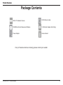
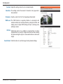
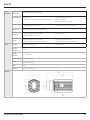
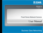
Version 1.00 | 09/01/2014
User Manual
HD Day and Night WDR Camera with Lowlight+
DCS-3714

Preface
D-Link reserves the right to revise this publication and to make changes in the content hereof without obligation to notify any
person or organization of such revisions or changes. Information in this document may become obsolete as our services and
websites develop and change.
Manual Revisions
Revision
Date
Description
1.0
April 11, 2014
DCS-3714 Revision A1 with firmware version V1.00
Trademarks
D-Link and the D-Link logo are trademarks or registered trademarks of D-Link Corporation or its subsidiaries in the United States or
other countries. All other company or product names mentioned herein are trademarks or registered trademarks of their respective
companies.
Copyright © 2014 D-Link Corporation.
All rights reserved. This publication may not be reproduced, in whole or in part, without prior expressed written permission from D-Link
Systems, Inc.
D-Link DCS-3714 User Manual
2

Table of Contents
Product Overview......................................................... 4
Package Contents.................................................... 4
Introduction............................................................... 5
System Requirements........................................ 5
Features................................................................... 6
Hardware Overview...................................................... 7
Hardware Overview.................................................. 7
Rear.................................................................... 7
Front................................................................... 8
Configuration with Wizard....................................... 11
Configuration.............................................................. 16
Web-based Configuration Utility............................. 16
Live Video............................................................... 18
Setup...................................................................... 20
Wizard............................................................... 20
Internet Connection Setup Wizard.................... 20
Motion Detection Setup Wizard........................ 23
Network Setup.................................................. 25
Dynamic DNS................................................... 28
Image Setup..................................................... 29
Audio and Video............................................... 31
Preset............................................................... 33
Motion Detection............................................... 35
Time and Date.................................................. 36
Event Setup...................................................... 37
D-Link DCS-3714 User Manual
Application........................................................ 38
Add Server........................................................ 39
Add Media......................................................... 40
SD Card............................................................ 46
Advanced................................................................ 47
Digital Input/Output........................................... 47
RS-485.............................................................. 48
ICR.................................................................... 49
HTTPS.............................................................. 50
Access List........................................................ 51
SNMP..................................................................... 52
Maintenance........................................................... 54
Device Management......................................... 54
Backup and Restore......................................... 55
Firmware Upgrade............................................ 56
Status..................................................................... 57
Device Info........................................................ 57
Logs.................................................................. 58
Help.................................................................. 59
Appendix..................................................................... 60
DI/DO Schematics.................................................. 60
DI/DO...................................................................... 60
Technical Specifications......................................... 61
3
Product Overview
Package Contents
DCS-3714 Network Camera
CAT5 Ethernet cable
CD-ROM with User Manual and Software
C-CS Mount Adapter (5mm Ring)
Power Adapter
Camera Stand
If any of the above items are missing, please contact your reseller.
D-Link DCS-3714 User Manual
4
Product Overview
Introduction
The DCS-3714 HD Day and Night WDR Camera with Lowlight+ is a professional surveillance and security solution for small,
medium, and large enterprises. The DCS-3714 uses a 1.3 megapixel progressive scan CMOS sensor which produces high
quality images with low noise allowing the DCS-3714 to provide outstanding performance with color night vision in low lightconditions, resulting in more vibrant color detail regardless of the amount of light available. The noise reduction feature has
been upgraded and enhanced as well to provide a level of detail in the image quality that is unmatched by other offerings in
the market. In addition, the DCS-3714 has Wide Dynamic Range (WDR) enhancement, users can identify image details in both
extremely bright and dark conditions.
The DCS-3714 has a built-in removable IR-cut filter for day/night functionality which provides clear detail and high quality
video at any hour of the day. The DCS-3714 incorporates Power over Ethernet (PoE) and an SD card slot, allowing it to be
easily installed in a variety of locations. The DCS-3714 input and output ports allow connectivity to external devices such as
IR sensors, switches, and alarm relays. It also comes with an RS-485 interface, providing connectivity to an optional pan/tilt
enclosure which effectively adds pan/tilt functionality to the DCS-3714. An additional 12 V interface provides power for an
optional LED illuminator. This combination of features makes the DCS-3714 a high-performance, reliable and cost-effective
24-hour megapixel surveillance solution.
System Requirements
•
•
•
•
•
•
Computer with Microsoft Windows® 8, 7, Vista®, or XP (for CD-ROM Setup Wizard), Mac OS® X or Linux
PC with 1.3GHz processor or above, and at least 128MB RAM
Internet Explorer® 7 or above , Firefox® 3.5 or above, Safari® 4 and Chrome™ 8.0 or above
Existing 10/100 Ethernet-based network
A SD memory card (optional) is required for recording to onboard storage. SDHC Class 6 or above is recommended.
Broadband Internet connection
D-Link DCS-3714 User Manual
5
Product Overview
Features
High-Quality Color Night Vision
The DCS-3714 provides outstanding performance in low light-conditions, resulting in more vibrant color detail regardless of the amount of
lightavailable.
Wide Dynamic Range
Wide Dynamic Range technology corrects imperfect lighting conditions, providing clear images with the right amount of contrast even when a
subject is backlit.
Remote Monitoring Utility
The D-ViewCam application adds enhanced features and functionality for the DCS-3714 and allows administrators to configure and access the
Network Camera from a remote site via Intranet or Internet. Other features include image monitoring, recording images to a hard drive, viewing
up to 32 cameras on one screen, and taking snapshots.
PoE (Power over Ethernet) for Streamlined Installation
The DCS-3714 can get all the power it needs from a PoE switch or PoE injector, for a simple and clutter-free installation.
All-Day Surveillance with low light color image capability
The built-in Sony sensor allows you to monitor an area during the night with full color images. The DCS-3714 provides clear detail and high quality
video at any hour of the day by automatically adjusting its a built-in removable IR-cut filter.
Add External Controls or Devices
An integrated RS-485 interface provides connectivity to an optional pan/tilt enclosure which effectively adds pan/tilt functionality to the DCS-3714
while input and output ports allow connectivity to external devices such as IR sensors, switches, and alarm relays..
D-Link DCS-3714 User Manual
6
Hardware Overview
Hardware Overview
Rear
1
2
8
3
4
5
6
7
1
Ethernet (PoE)
RJ-45 connector for Ethernet which can also be used to power the camera using PoE
2
DC Power
12 V DC
3
Audio In
Audio input connector for a microphone
4
Reset
Press and hold this button for 5 seconds to reset the camera
5
BNC
Analog video output
6
Audio Out
Audio output for external speakers
7
I/O Connector
I/O connectors for external devices
8
LED
Power and network indicator
D-Link DCS-3714 User Manual
7
Hardware Overview
Front
1
2
1
Lens Connector
Connect to a CS mount
2
ICR Sensor
The IR-Cut Removable sensor judges lighting conditions and switches from color to infrared accordingly
D-Link DCS-3714 User Manual
8
Hardware Overview
1
2
1. AES: Auto Electric Shutter
2. DC IRIS: Use an auto iris (DC drive)
1
DC-Iris Connector
Connector for DC auto Iris lens
2
DIP Switch
Toggles between several
regional formats
3. NTSC: TV output signal selector
4. PAL: TV output signal selector
D-Link DCS-3714 User Manual
9
Hardware Overview
1
1
SD Card Slot
D-Link DCS-3714 User Manual
Local SD Card for storing recorded images and video
10
Hardware Overview
Configuration with Wizard
Insert the DCS-3714 CD into your computer's CD-ROM drive to begin the installation. If the Autorun function on your computer is
disabled, or if the D-Link Launcher fails to start automatically, click Start > Run. Type D:\autorun.exe, where D: represents the drive
letter of your CD-ROM drive.
Click Installation Wizard to begin the installation.
After clicking Setup Wizard, the window on the right will open.
Click Next to continue.
D-Link DCS-3714 User Manual
11
Hardware Overview
Click Yes to accept the License Agreement.
To start the installation process, click Next.
Note: The installation may take several minutes to finish.
D-Link DCS-3714 User Manual
12
Hardware Overview
Click Finish to complete the installation.
Click on the D-Link Setup Wizard SE icon that was created in your Windows
Start menu.
Start > D-Link > Setup Wizard SE
D-Link DCS-3714 User Manual
13
Hardware Overview
The Setup Wizard will appear and display the MAC address and IP address of
your camera(s). If you have a DHCP server on your network, a valid IP Address
will be displayed. If your network does not use a DHCP server, the network
camera's default static IP address 192.168.0.20 will be displayed.
Click the Wizard button to continue.
Enter the Admin ID and password. When logging in for the first time, the default
Admin ID is admin with the password left blank.
Click Next, to proceed to the next page.
D-Link DCS-3714 User Manual
14
Hardware Overview
Select DHCP if your camera obtains an IP address automatically when it boots up.
Select static IP if the camera will use the same IP address each time it is started.
Click Next, to proceed to the next page.
Take a moment to confirm your settings and click Restart.
D-Link DCS-3714 User Manual
15
Configuration
Web-based Configuration Utility
This section explains how to configure your new D-Link Network Camera using the Web-based Configuration Utility.
Click on the D-Link Setup Wizard SE icon that was created in your Windows
Start menu.
Start > D-Link > Setup Wizard SE
Select the camera and click the button labeled "Link" to access the web
configuration.
The Setup Wizard will automatically open your web browser to the IP address of
the camera.
Alternatively, you may manually open a browser and enter the IP address of the
camera: 192.168.0.20
D-Link DCS-3714 User Manual
16
Configuration
Enter admin as the default username and leave the password blank. Click OK to
continue.
This section shows your camera’s live video. You can select your video profile and
view or operate the camera. For additional information about web configuration,
please refer to the user manual included on the CD-ROM or the D-Link website.
D-Link DCS-3714 User Manual
17
Configuration
Live Video
This section shows your camera’s live video. You may select any of the available icons listed below to operate the camera. You may
also select your language using the drop-down menu on the left side of the screen.
You can zoom in and out on the live video image using your mouse. Right-click to zoom out or left-click to zoom in on the image.
Digital Input
Indicator
Motion Trigger
Indicator
This indicator will change color when a digital
input signal is detected.
This indicator will change color when a trigger
event occurs.
Recording
Indicator
Note: The video motion feature for your
camera must be enabled.
When a recording is in progress, this indicator
will change color.
Video Profile 1
Video Profile 2
Video Profile 3
Full screen mode
Taking a Snapshot
Recording a Video Clip
Set a Storage Folder
Listen/Stop Listening
Talk/Stop Talking
Control Pad
This control pad can be used to pan, tilt, and zoom
within the camera's predefined view area, if one
has been defined.
Start/Stop Digital Output
D-Link DCS-3714 User Manual
18
Configuration
Go To: If any presets have been defined, selecting a preset from this list
(Preset List) will display it.
SD Status: This option displays the status of the SD card. If no SD card has
been inserted, this screen will display the message "Card Invalid."
IO Status: This option displays the status of your I/O device if a device has
been connected.
PTZ Control: This camera uses electronic pan/tilt/zoom (ePTZ) to select and
view areas of interest in the field of view. Please see "Audio and
Video" on page 31 for information about setting the frame size
and view window area.
ePTZ Speed: You may select a value between 0 and 64. 0 is the slowest and 64
is the fastest.
Global View: This window indicates the total field of view (FOV) of the camera.
The red box indicates the visible region of interest (ROI).
Language: You may select the interface language using this menu. The
available options are English and Traditional Chinese.
Auto Pan
Stop
Preset Path
D-Link DCS-3714 User Manual
Starts the automatic
panning function. The
ROI will pan from back
and forth within the
FOV
Stops the camera
ePTZ motion
Starts the camera's
motion along the
predefined path
19
Configuration
Setup
Wizard
To configure your Network Camera, click Internet Connection
Setup Wizard. Alternatively, you may click Manual Internet
Connection Setup to manually configure your Network Camera and
skip to "Network Setup" on page 25.
To quickly configure your Network Camera’s motion detection
settings, click Motion Detection Setup Wizard. If you want to
enter your settings without running the wizard, click Manual Motion
Detection Setup and skip to "Motion Detection" on page 35.
Internet Connection Setup Wizard
This wizard will guide you through a step-by-step process to
configure your new D-Link Camera and connect the camera to the
internet. Click Next to continue.
Note: Select DHCP if you are unsure of which settings to choose.
Click Next to continue.
D-Link DCS-3714 User Manual
20
Configuration
Select Static IP if your Internet Service Provider has provided you with
connection settings, or if you wish to set a static address within your
home network. Enter the correct configuration information and click Next
to continue.
If you are using PPPoE, select Enable PPPoE and enter your user name
and password, otherwise click Next to continue.
If you have a Dynamic DNS account and would like the camera to update
your IP address automatically, Select Enable DDNS and enter your host
information. Click Next to continue.
Enter a name for your camera and click Next to continue.
D-Link DCS-3714 User Manual
21
Configuration
Configure the correct time to ensure that all events will be
triggered as scheduled. Click Next to continue.
If you have selected DHCP, you will see a summary of your
settings, including the camera's IP address. Please write down
all of this information as you will need it in order to access your
camera.
Click Apply to save your settings.
D-Link DCS-3714 User Manual
22
Configuration
Motion Detection Setup Wizard
This wizard will guide you through a step-by-step process to configure your
camera's motion detection functions.
Click Next to continue.
Step 1
This step will allow you to enable or disable motion detection, specify the
detection sensitivity, and adjust the camera’s ability to detect movement.
You may specify whether the camera should capture a snapshot or a video
clip when motion is detected.
Please see the Motion Detection section on "Motion Detection" on page
35 for information about how to configure motion detection.
Step 2
This step allows you to enable motion detection based on a customized
schedule. Specify the day and hours. You may also choose to always
record motion.
D-Link DCS-3714 User Manual
23
Configuration
Step 3
This step allows you to specify how you will receive event notifications
from your camera. You may choose not to receive notifications, or to
receive notifications via e-mail or FTP.
Please enter the relevant information for your e-mail or FTP account.
Click Next to continue.
Step 4
You have completed the Motion Detection Wizard.
Please verify your settings and click Apply to save them.
Please wait a few moments while the camera saves your settings and
restarts.
D-Link DCS-3714 User Manual
24
Configuration
Network Setup
Use this section to configure the network connections for your camera. All relevant information must be entered accurately.
LAN Settings: Settings for your local area network.
DHCP: Select this connection if you have a DHCP server running on
your network and would like your camera to obtain an IP address
automatically.
Static IP You may obtain a static or fixed IP address and other network
Address: information from your network administrator for your camera. A
static IP address may simplify access to your camera in the future.
IP Address: Enter the fixed IP address in this field.
Subnet Mask: This number is used to determine if the destination is in the same
subnet. The default value is 255.255.255.0.
Default Gateway: The gateway used to forward frames to destinations in a different
subnet. Invalid gateway settings may cause the failure of
transmissions to a different subnet.
Primary DNS: The primary domain name server translates names to IP addresses.
Secondary DNS: The secondary DNS acts as a backup to the primary DNS.
Enable UPnP: Enabling this setting allows your camera to be configured as a
UPnP device on your network.
Enable UPnP Enabling this setting allows the camera to add port forwarding
Port Forwarding: entries into the router automatically on a UPnP capable network.
D-Link DCS-3714 User Manual
25
Configuration
Enable PPPoE: Enable this setting if your network uses PPPoE.
User Name: The unique name of your account. You may obtain this information
from your ISP.
Password: The password to your account. You may obtain this information
from your ISP.
HTTP Port: The default port number is 80.
Access Name for The default name is video#.mjpg, where # is the number of the
Stream 1~3: stream.
HTTPS Port: You may use a PC with a secure browser to connect to the HTTPS
port of the camera. The default port number is 443.
Authentication: Choose to enable or disable RTSP digest encryption. Digest
encryption uses MD5 hashes.
RTSP Port: The port number that you use for RTSP streaming to mobile
devices, such as mobile phones or PDAs. The default
port number is 554. You may specify the address of a
particular stream. For instance, live1.sdp can be accessed at
rtsp://x.x.x.x/video1.sdp where the x.x.x.x represents the ip address
of your camera.
D-Link DCS-3714 User Manual
26
Configuration
Enable CoS: Enabling the Class of Service setting implements a best-effort
policy without making any bandwidth reservations.
Enable QoS: Enabling QoS allows you to specify a traffic priority policy to
ensure a consistent Quality of Service during busy periods. If the
Network Camera is connected to a router that itself implements
QoS, the router's settings will override the QoS settings of the
camera.
Enable IPv6: Enable the IPv6 setting to use the IPv6 protocol. Enabling the
option allows you to manually set up the address, specify an
optional IP address, specify an optional router and an optional
primary DNS.
Enable Multicast The DCS-3714 allows you to multicast each of the available
for stream streams via group address and specify the TTL value for each
stream. Enter the port and TTL settings you wish to use if you do
not want to use the defaults.
D-Link DCS-3714 User Manual
27
Configuration
Dynamic DNS
DDNS (Dynamic Domain Name Server) will hold a DNS host name and synchronize the public IP address of the modem when it has
been modified. A user name and password are required when using the DDNS service.
Enable DDNS: Select this checkbox to enable the DDNS function.
Server Address: Select your Dynamic DNS provider from the pull down menu or
enter the server address manually.
Host Name: Enter the host name of the DDNS server.
User Name: Enter your user name or e-mail used to connect to the DDNS.
Password: Enter your password used to connect to the DDNS server.
Timeout: Enter DNS Timeout values.
Status: Indicates the connection status, which is automatically determined
by the system.
D-Link DCS-3714 User Manual
28
Configuration
Image Setup
In this section, you may configure the video image settings for your camera. A preview of the image will be shown in Live Video.
Enable Privacy The Privacy Mask setting allows you to specify upto 3 rectangular
Mask: areas on the camera's image to beblocked/excluded from recordings
and snapshots.
You may click and drag the mouse cursor over thecamera image
to draw a mask area.Right clicking on the camera image brings up
thefollowing menu options:
Disable All: Disables all mask areas
Enable All: Enables all mask areas
Reset All: Clears all mask areas.
Mirror: Mirrors the images.
Flip: Rotates the image 180 degrees.
White Balance: If this option is enabled, white objects will be rendered as white on
the screen.
Exposure Mode: Changes the exposure mode. Use the dropdown box to set the
camera for Indoor, Outdoor, or Night environments, or to capture
Moving objects. The Low_Noise option will focus on creating a highquality picture without noise. You can also create 3 different custom
exposure modes. The Max Gain setting will allow you to control the
maximum amount of gain to apply to brighten the picture.
Denoise: This setting controls the amount of noise reduction that will be
applied to the picture.
Brightness: Adjust this setting to compensate for backlit subjects.
D-Link DCS-3714 User Manual
29
Configuration
Contrast: Adjust this setting to alter the color intensity/strength.
Saturation: This setting controls the amount of coloration, from grayscale to
fully saturated.
Sharpness: Specify a value from 0 to 8 for image edge enhancement.
WDR Level: The WDR function is especially effective in environment with
extreme contrast such as lobby entrances, parking lots, ATMs, and
loading areas. A higher WDR setting will help in reducing areas
with high contrast.
3D Filter: Setting this option to Low, Medium, or High will help to reduce
image artifacts, and result in images with less blur when viewing
the camera during the night or in areas where there are low levels
of light.
Reset Default: Click this button to reset the image to factory default settings.
D-Link DCS-3714 User Manual
30
Configuration
Audio and Video
You may configure up to 3 video profiles with different settings for your camera. Hence, you may set up different profiles for your
computer and mobile display. In addition, you may also configure the two-way audio settings for your camera.
Number of active You can use the dropdown box to set up to 3 active profiles.
profiles:
Aspect ratio: Set the aspect ratio of the video to 4:3 standard or 16:9 widescreen.
Mode: Set the video codec to be used to JPEG, MPEG-4, or H.264.
Frame size / View Frame size determines the total capture resolution, and View
window area: window area determines the Live Video viewing window size. If
the Frame size is larger than the Live Video size, you can use the
ePTZ controls to look around.
16:9 1280x720, 800x450, 640x360, 480x270, 320x176
4:3 1024x768, 800x600, 640x480, 480x 360, 320x240
Intra Frame Select which frame in which a complete image is stored in the video
Period: stream. This frame will be used as a reference for the compression
algorithm.
Maximum frame A higher frame rate provides smoother motion for videos. Lower
rate: frame rates will result in stuttering motion. The maximum number
of frames that is displayed in 1 second. 30 fps is the highest video
quality for this camera. In general, any frame rate above 15 fps is
imperceptible to the human eye.
Video Quality: This limits the maximal refresh frame rate, which can be combined
with the "Fixed quality" option to optimize the bandwidth utilization
and video quality. If fixed bandwidth utilization is desired regardless
of the video quality, choose "Constant bit rate" and select the
desired bandwidth.
D-Link DCS-3714 User Manual
31
Configuration
Constant bit rate: The bps will affect the bit rate of the video recorded by the camera.
Higher bit rates result in higher video quality.
Fixed quality: Select the image quality level for the camera to try to maintain.
High quality levels will result in increased bit rates.
Encoding: Set the audio codec to be used to G.711 or AAC. This will allow you
to control the quality of audio captured, at the expense of increased
use of bandwidth.
Audio in off: Ticking this checkbox will mute incoming audio.
Audio in gain This setting controls the amount of gain applied to incoming audio
level: to increase its volume.
Audio out off: Ticking this checkbox will mute outgoing audio.
Audio out This setting controls the amount of gain applied to outgoing audio
volume level: to increase its volume.
D-Link DCS-3714 User Manual
32
Configuration
Preset
This screen allows you to set preset points for the ePTZ function of the camera, which allows you to look around the camera's viewable
area by using a zoomed view. Presets allow you to quickly go to and view a specific part of the area your camera is covering, and you
can create preset sequences, which will automatically change the camera's view between the different presets according to a defined
order and timing you can set.
Note: If your View window area is the same as your Frame size, you will not be able to use the ePTZ function.
Video Profile: This selects which video profile to use.
ePTZ Speed: You may select a value between 0 and 64. 0 is the slowest and 64
is the fastest.
Arrow Buttons Use these buttons to move to a specific part of the viewing area,
and Home which you can then set as a preset. Click the Home button to return
Button: to the center of the viewing area.
Input Preset Enter the name of the preset you want to create, then click the
Name: Add button to make a new preset. If an existing preset has been
selected from the Preset List, you can change its name by typing in
a new name, then clicking the Rename button.
Preset List: Click this drop-down box to see a list of all the presets that have
been created. You can select one, then click the GoTo button
to change the displayed camera view to the preset. Clicking the
Remove button will delete the currently selected preset.
D-Link DCS-3714 User Manual
33
Configuration
Preset This section allows you to create a preset sequence, which
Sequence: automatically moves the camera's view between a set of preset
views.
Preset List: To add a preset to the sequence, select it from the drop-down box
at the bottom of this window, set the Dwell time to determine how
long the camera view will stay at that preset, then click the Add
button. The preset name will appear in the list, followed by the dwell
time to view that preset for.
You can rearrange your presets in the sequence by selecting a
preset in the sequence, then clicking the arrow buttons to move it
higher or lower in the current sequence.
Clicking the trash can button will remove the currently selected
preset from the sequence.
If you want to change the dwell time for a preset, select it from the
list, enter a new dwell time, then click the Update button.
D-Link DCS-3714 User Manual
34
Configuration
Motion Detection
Enabling Video Motion will allow your camera to use the motion detection feature. You may draw a finite motion area that will be used
for monitoring.
Enable Video Select this box to enable the motion detection feature of your
Motion: camera.
Sensitivity: Specifies the measurable difference between two sequential
images that would indicate motion. Please enter a value between
0 and 100.
Percentage: Specifies the amount of motion in the window being monitored
that is required to initiate an alert. If this is set to 100%, motion is
detected within the whole window will trigger a snapshot.
Draw Motion Draw the motion detection area by dragging your mouse in the
Area: window (indicated by the red square).
Erase Motion To erase a motion detection area, simply click on the red square
Area: that you wish to remove.
Right clicking on the camera image brings up the following menu
options:
Select All: Draws a motion detection area over the entire screen.
Clear All: Clears any motion detection areas that have been drawn.
Restore: Restores the previously specified motion detection areas.
D-Link DCS-3714 User Manual
35
Configuration
Time and Date
This section allows you to automatically or manually configure, update, and maintain the internal system clock for your camera.
Time Zone: Select your time zone from the drop-down menu.
Enable Daylight Select this to enable Daylight Saving Time.
Saving:
Auto Daylight Select this option to allow your camera to configure the Daylight
Saving: Saving settings automatically.
Set Date and Selecting this option allows you to configure the Daylight Saving
Time Manually: date and time manually.
Offset: Sets the amount of time to be added or removed when Daylight
Saving is enabled.
Synchronize with Enable this feature to obtain time automatically from an NTP server.
NTP Server:
NTP Server: Network Time Protocol (NTP) synchronizes the DCS-3714 with an
Internet time server. Choose the one that is closest to your location.
Set the Date and This option allows you to set the time and date manually.
Time Manually:
Copy Your This will synchronize the time information from your PC.
Computer's Time
Settings:
D-Link DCS-3714 User Manual
36
Configuration
Event Setup
The Event Setup page includes 4 different sections.
• Event
• Server
• Media
• Recording
1. To add a new item - "event, server or media," click Add. A screen will appear and
allow you to update the fields accordingly.
2. To delete the selected item from the pull-down menu of event, server or media, click
Delete.
3. Click on the item name to pop up a window for modifying.
Note: You can add up to four events, five servers, and five media fields.
D-Link DCS-3714 User Manual
37
Configuration
Application
In a typical application, when motion is detected, the DCS-3714 Network Camera sends images to a FTP server or via e-mail as
notifications. As shown in the illustration below, an event can be triggered by many sources, such as motion detection or external digital
input devices. When an event is triggered, a specified action will be performed. You can configure the Network Camera to send snapshots
or videos to your e-mail address or FTP site.
Action
Event Condition
ex.
Motion detection,
Periodically, Digital input,
System reboot
Media
(what to send)
ex.
Snapshot, Video Clips
Server
(where to send)
ex.
Email, FTP
To start plotting an event, it is suggested to configure server and media columns first so that the Network Camera will know what action
shall be performed when a trigger is activated.
D-Link DCS-3714 User Manual
38
Configuration
Add Server
Configure up to 5 servers to store media.
Server Name: Enter the unique name of your server.
E-mail: Enter the configuration for the target e-mail server account.
FTP: Enter the configuration for the target FTP server account.
Network Storage: Specify a network storage device. Only one network storage device
is supported.
SD Card: Use the camera's onboard SD card storage.
D-Link DCS-3714 User Manual
39
Configuration
Add Media
There are three types of media, Snapshot, Video Clip and System Log.
Media Name: Enter an unique name for media.
Snapshot: Select this option to enable snapshots.
Source: The stream source: Profile 1, Profile 2 or Profile 3.
Send pre-event The number of pre-event images.
image(s) [0~4]:
Send post-event The number of post-event images.
image(s) [0~7]:
File name prefix: The prefix name will be added on the file name.
Add date and Check it to add timing information as file name suffix.
time suffix to file
name:
Video clip: Select this option to enable video clips.
Source: The source of the profile: profile1, profile2, or profile3.
Pre-event The interval of pre-event recording in seconds.
recording:
Maximum The maximal recording file duration in seconds.
duration:
Maximum file The maximal file size would be generated.
size:
File name prefix: The prefix name will be added on the file name of the video clip.
System log: Select this option to save events to the camera system log.
D-Link DCS-3714 User Manual
40
Configuration
Send post-event image (s) [0~7)
Specify to capture the number of images after a trigger is activated. A maximum of seven images can be generated.
For example:
If both the Send pre-event images and Send post-event images are set to four, a total of 9 images are generated after a trigger is activated.
1 pic.
2 pic.
3 pic.
4 pic.
5 pic.
6 pic.
7 pic.
8 pic.
9 pic.
The moment the
trigger is activated.
Add a date and time suffix to the file name
Select this option to add a date and time to the file name suffix.
SNAPSHOTS20080104_100341
File name prefix Date and time suffix
The format is: YYYYMMDD_HHMMSS
Maximum duration
Specify the maximal recording duration in seconds. You can set up to ten seconds.
For example:
If the Pre-event recording is set to five seconds and the Maximum duration is set to ten seconds, the Network Camera continues to record
for another four seconds after a trigger is activated.
D-Link DCS-3714 User Manual
41
Configuration
1 sec.
2 sec.
3 sec.
4 sec.
5 sec.
6 sec.
7 sec.
8 sec.
9 sec.
10 sec.
The moment the
trigger is activated.
File name prefix
Enter the text that will be added at the beginning of the file name.
VIDEOS20080104_100341
File name prefix Date and time suffix
The format is: YYYYMMDD_HHMMSS
D-Link DCS-3714 User Manual
42
Configuration
Add Event
Create and schedule up to 3 events with their own settings here.
Event name: Enter a name for the event.
Enable this Select this box to activate this event.
event:
Priority: Set the priority for this event. The event with higher priority will be
executed first.
Delay: Select the delay time before checking the next event. It is being
used for both events of motion detection and digital input trigger.
Trigger: Specify the input type that triggers the event.
Video Motion Motion is detected during live video monitoring. Select the windows
Detection: that need to be monitored.
Periodic: The event is triggered in specified intervals. The trigger interval unit
is in minutes.
Digital input: The external trigger input to the camera.
System Boot: Triggers an event when the system boots up.
Network Lost: Triggers an event when if the network connection is lost.
Event Schedule: Select Always or enter the time interval.
Trigger D/O: Select to trigger the digital output for a specific number of seconds
when an event occurs.
D-Link DCS-3714 User Manual
43
Configuration
Add Recording
Here you can configure and schedule the recording settings.
Recording entry The unique name of the entry.
name:
Enable this Select this to enable the recording function.
recording:
Priority: Set the priority for this entry. The entry with a higher priority value
will be executed first.
Source: The image profile used for the source of the stream.
Recording Scheduling the recording entry.
schedule:
Recording Configuring the setting for the recording.
settings:
Destination: Select the folder where the recording file will be stored.
Total cycling Please input a HDD volume between 1MB and 2TB for recording
recording size: space. The recording data will replace the oldest record when
the total recording size exceeds this value. For example, if each
recording file is 6MB, and the total cyclical recording size is 600MB,
then the camera will record 100 files in the specified location (folder)
and then will delete the oldest file and create new file for cyclical
recording.
Please note that if the free HDD space is not enough, the recording
will stop. Before you set up this option please make sure your HDD
has enough space, and it is better to not save other files in the
same folder as recording files.
D-Link DCS-3714 User Manual
44
Configuration
Size of each file If this is selected, files will be separated based on the file size you
for recording: specify.
Time of each file If this is selected, files will be separated based on the maximum
for recording: length you specify.
File Name Prefix: The prefix name will be added on the file name of the recording
file(s).
D-Link DCS-3714 User Manual
45
Configuration
SD Card
Here you may browse and manage the recorded files which are stored on the SD card.
Format SD Card: Click this icon to automatically format the SD card and create
"picture" & "video" folders.
View Recorded If the picture files are stored on the SD card, click on the picture
Picture: folder and choose the picture file you would like to view.
Playback If video files are stored on the SD card, click on the video folder and
Recorded Video: choose the video file you would like to view.
Refresh: Reloads the file and folder information from the SD card.
D-Link DCS-3714 User Manual
46
Configuration
Advanced
Digital Input/Output
This screen allows you to control the behavior of digital input and digital output devices. The I/O connector provides the physical
interface for digital output (DO) and digital input (DI) that is used for connecting a diversity of external alarm devices such as IR-Sensors
and alarm relays. The digital input is used for connecting external alarm devices and once triggered images will be taken and e-mailed.
Select D/I or D/O The camera will send a signal when an event is triggered, depending
Mode: upon the type of device connected to the DI circuit.
N.C. stands for Normally Closed. This means that the normal
state of the circuit is closed. Therefore events are triggered when
the device status changes to "Open."
N.O. stands for Normally Open. This means that the normal state
of the circuit is open. Therefore events are triggered when the
device status changes to "Closed."
Video Output: Enable/ disable the BNC terminal TV output signal.
D/I and D/O
Pin Block
D-Link DCS-3714 User Manual
47
Configuration
RS-485
You may configure the RS-485 settings or communication specifications (baud rate, data bit, stop bit, and parity bit) for your camera.
RS-485 is a serial communication method for computers and devices. RS-485 is used to control a PAN/TILT apparatus, such as an
external camera enclosure.
Support When Support PAN-TILT is enabled, a control panel will be
PAN-TILT: displayed on the Live Video page allowing control through RS-485
for an external camera enclosure.
Protocol: Select one protocol type from the pull-down menu.
ID: This ID is the identifier for RS-485 devices. IDs range from 1 to 255.
Baud Rate: Baud Rate is a speed measurement for communication between a
transmitter and receiver which indicates the number of bit transfers
per second. A higher baud rate will reduce the distance of the
two devices (transmitter and receiver). Values range from 2400
(default) to 19200 bps.
Data Bit: This value is the number of data bits in a transmission. The data bit
can be 7 or 8 (default).
Parity Bit: Parity is a form of error checking used in serial communication. For
even and odd parities, the serial port sets the parity bit (the last bit
after the data bits) to a value to ensure that the transmission has
an even or odd number of logic-high bits. For example, if the data is
011, for even parity, the parity bit is 0 to keep the number of logichigh bits even. If the parity is odd, the parity bit is 1, resulting in 3
logic-high bits. Parity can be set to No (none), Even, and Odd.
RS-485
Pin Block
Stop Bit: The stop bit is used to signal the end of communication for a
single packet. The more bits used for stop bits, the greater the
lenience in synchronizing the different clocks but the slower the
data transmission rate. The stop bit can be set to 1 or 2. The default
value is 1.
D-Link DCS-3714 User Manual
48
Configuration
ICR
You may configure the ICR settings here. An IR(Infrared) Cut-Removable(ICR) filter can be disengaged for increased sensitivity in low
light environments.
Automatic: The Day/Night mode is set automatically. Generally, the camera
uses Day mode and switches to Night mode when needed.
Day Mode: Day mode enables the IR Cut Filter.
Night Mode: Night mode disables the IR Cut Filter.
Schedule Mode: Set up the Day/Night mode using a schedule. The camera will
enter Day mode at the starting time and return to Night mode at the
ending time.
DC Power The DC 12V Power Output port can supply 12V DC, 100mA of
Output: power to another device (such as a spotlight or infrared lamp). Its
default setting is Off, meaning it will not supply power. You can
select On to turn on the power supply. If you choose Sync With
ICR, the power output will be enabled whenever the IR Cut Filter
is active. Alternatively, you can select Schedule and manually
specify when the power should be enabled.
DC Power Output
12V DC, 100mA
D-Link DCS-3714 User Manual
49
Configuration
HTTPS
This page allows you to install and activate an HTTPS certificate for secure access to your camera.
Enable HTTPS Enable the HTTPS service.
Secure
Connection:
Create Certificate Choose the way the certificate should be created. Three options
Method: are available:
Create a self-signed certificate automatically
Create a self-signed certificate manually
Create a certificate request and install
Status: Displays the status of the certificate.
Note: The certificate cannot be removed while the HTTPS is still enabled.
To remove the certificate you must first uncheck Enable HTTPS
secure connection.
D-Link DCS-3714 User Manual
50
Configuration
Access List
Here you can set access permissions for users to view your DCS-3714.
Allow list: The list of IP addresses that have the access right to the camera.
Start IP address: The starting IP Address of the devices (such as a computer) that
have permission to access the video of the camera. Click Add to
save the changes made.
Note: A total of seven lists can be configured for both columns.
End IP address: The ending IP Address of the devices (such as a computer) that
have permission to access the video of the camera.
Delete allow list: Remove the customized setting from the Allow List.
Deny list: The list of IP addresses that have no access right to the camera.
Delete deny list: Remove the customized setting from the Delete List.
For example:
When the range of the Allowed List is set from 1.1.1.0 to
192.255.255.255 and the range of the Denied List is set from
1.1.1.0 to 170.255.255.255. Only users with IPs located between
171.0.0.0 and 192.255.255.255 can access the Network Camera.
Alowed
List
D-Link DCS-3714 User Manual
Denied
List
51
Configuration
SNMP
SNMP (Simple Network Management Protocol) is a widely used network monitoring and control protocol that reports activity on each
network device to the administrator of the network. SNMP can be used to monitor traffic and statistics of the DCS-3714. The DCS-3714
supports SNMP v1, v2c, and v3. After modifying any settings, click Save Settings to save your changes.
Enable SNMPv1, Select whether to Enable or Disable SNMPv1 or SNMPv2c
SNMPv2c: administration.
Read/Write Enter the private name in this field to enable read/write access to
community: the network using SNMP.
Read only Enter the public name in this field to allow read-only access to
community: network administration using SNMP. You can view the network, but
no configuration is possible with this setting.
Enable SNMPv3: Select whether to Enable or Disable SNMPv3 administration.
Read/Write Enter the private name in this field to enable read/write access to
Security Name: the network using SNMP.
Authentication Select the authentication type that matches with the remote
Type: SNMP server.
Authentication Enter the SNMP authentication password in this field.
Password:
Encryption Enter the SNMP encryption password in this field.
Password:
D-Link DCS-3714 User Manual
52
Configuration
Read Only Enter the Read only security name in this field to enable read
Security Name: only access to the network using SNMP.
Authentication Select the authentication type that matches with the remote
Type: SNMP server.
Authentication Enter the SNMP authentication password in this field.
Password:
Encryption Enter the SNMP encryption password in this field
Password:
D-Link DCS-3714 User Manual
53
Configuration
Maintenance
Device Management
You may modify the name and administrator’s password of your camera, as well as add and manage the user accounts for accessing
the camera. You may also use this section to create the unique name and configure the OSD setting for your camera.
Admin Password Set a new password for the administrator’s account.
Setting:
Add User Add new user account.
Account:
User Name: The user name for the new account.
Password: The password for the new account.
User List: All the existing user accounts will be displayed here. You may
delete accounts includes in the list, but please reserve at least one
as guest.
Camera Name: Create a unique name for your camera that will be added to the file
name prefix when creating a snapshot or a video clip.
Enable OSD: Select this option to enable the On-Screen Display feature for your
camera.
Label: Enter a label for the camera.
Show Time: Select this option to enable the time-stamp display on the video
screen.
D-Link DCS-3714 User Manual
54
Configuration
Backup and Restore
In this section, you may backup, restore and reset the camera configuration, or reboot the camera.
Save To Local You may save and document your current settings into your
Hard Drive: computer.
Local From Local Locate a pre-saved configuration by clicking Browse and then
Hard Drive: restore the pre-defined settings to your camera by clicking Load
Configuration.
Restore to You may reset your camera and restore the factory settings by
Factory Default: clicking Restore Factory Defaults.
Reboot Device: This will restart your camera.
Enable Schedule Select this option to schedule a time for the device to reboot.
Reboot:
After making any changes, click the Save button to save your
changes.
D-Link DCS-3714 User Manual
55
Configuration
Firmware Upgrade
The camera's current firmware version will be displayed on this screen. You may visit the D-Link Support Website to check for the latest
available firmware version.
To upgrade the firmware on your DCS-3714, please download and save the latest firmware version from the D-Link Support Page to
your local hard drive. Locate the file on your local hard drive by clicking the Browse button. Select the file and click the Upload button
to start upgrading the firmware.
Current Firmware Displays the detected firmware version.
Version:
Current Product Displays the camera model name.
Name:
File Path: Locate the file (upgraded firmware) on your hard drive by clicking
Browse.
Upload: Uploads the new firmware to your camera.
D-Link DCS-3714 User Manual
56
Configuration
Status
Device Info
This page displays detailed information about your device and network connection.
D-Link DCS-3714 User Manual
57
Configuration
Logs
This page displays the log information of your camera. You may download the information by clicking Download. You may also click
Clear to delete the saved log information.
D-Link DCS-3714 User Manual
58
Configuration
Help
This page provides helpful information regarding camera operation.
D-Link DCS-3714 User Manual
59
Appendix
DI/DO Schematics
DI/DO
D-Link DCS-3714 User Manual
60
Appendix
Technical Specifications
Camera
Network
Camera Hardware
Profile
• 1/3” Megapixel progressive CMOS sensor
• Minimum illumination: 0.1 lux (Color)
• Built-in Infrared-Cut Removable (ICR) Filter module
• DC iris varifocal length: 2.9 mm to 8.2 mm
• Aperture: F1.0
• Angle of view:
• (H) 35.6° to 95°
• (V) 20° to 50.9°
• (D) 41° to 112.3°
• Minimum object distance 0.5m
Image Features
• Configurable image size, quality, frame rate, and bit rate
• Time stamp and text overlays
• Configurable motion detection windows
• Configurable privacy mask zones
• Configurable WDR, white balance, shutter speed, brightness, saturation,
contrast, and sharpness
Video Compression
• Simultaneous H.264/MPEG-4/MJPEG format compression
• JPEG for still images
• H.264/MPEG-4 multicast streaming
Video Resolution
• 16:9 - 1280 x 720, 800 x 450, 640 x 360, 480 x 270, 320 x 176 up to 30 fps
• 4:3 - 1024 x 768, 800 x 600, 640 x 480, 480 x 360, 320 x 240 up to 30 fps
Audio Support
• AAC
• G.711
External Device
Interface
• 2 DI / 1 DO interface
• 12 V DC, 100 mA Output
• RS-485
• Audio input / output
• Video output
• SD/SDHC/SDXC card Slot, accepts cards up to 64 GB
Network Protocols
• IPv6
• IPv4
• TCP/IP
• UDP
• ICMP
• DHCP client
• NTP client (D-Link)
• DNS client
• DDNS client (D-Link)
• SMTP client
• FTP client
• HTTP / HTTPS
• Samba client
• PPPoE
• UPnP port forwarding
• RTP / RTSP/ RTCP
• IP filtering
• QoS
• CoS
• Multicast
• ONVIF compliant
• SNMP
Security
• Administrator and user group protection
• Password authentication
• HTTP and RTSP authentication
D-Link DCS-3714 User Manual
61
Appendix
System
Management
General
System Requirements
for Web Interface
• Browser: Internet Explorer, Firefox, Chrome, Safari
Event Management
• Motion detection
• Event notification and uploading of snapshots/video clips via e-mail or FTP
• Supports multiple SMTP, and FTP servers
• Multiple event notifications
• Multiple recording methods for easy backup
Remote Management
• Configuration accessible via web browser
• Take snapshots/video clips and save to local hard drive
Mobile Support
• Windows2000/XP/Vista/Windows7/8/iPhone/iPad/Android
D-ViewCam™ System
Requirements
• Operating System: Microsoft Windows 8/7/Vista/XP
• Web Browser: Internet Explorer 7 or higher
• Protocol: Standard TCP/IP
D-ViewCam™ Software
Functions
• Remote management/control of up to 32 cameras
• Supports all management functions provided in web interface
• Viewing of up to 32 cameras on one screen
• Scheduled motion-triggered or manual recording options
Power Input
• Input: 100 to 240 V AC, 50/60 Hz
• Output: 12 V DC, 1.5 A
Max. Power
Consumption
• 4.8 watts
Operating
Temperature
• 0 to 40 ˚C (32 to 104 ˚F)
Storage Temperature
• -20 to 70 °C (-4 to 158 °F)
Humidity
• 20% to 80% non-condensing
Weight
• 545 g
Certifications
• CE (Class A), LVD, FCC (Class A), C-Tick
Dimensions
D-Link DCS-3714 User Manual
62