1
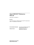
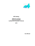
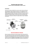
OKP 4221 DC CURRENT/VOLTAGE-TO-FREQUENCY CONVERTER "CVFC" User's Manual МС2.725.001 UM 2010 MARS-ENERGO CONTENTS INTRODUCTION....................................................................................................................... 3 1 SAFETY REQUIREMENTS .................................................................................................. 3 2 GENERAL DESCRIPTION AND OPERATION PRINCIPLE ......................................... 4 2.1 SCOPE OF APPLICATION ....................................................................................................... 4 2.2 OPERATING CONDITIONS ..................................................................................................... 4 2.3 CONTENTS OF CVFC DELIVERY PACKAGE ......................................................................... 5 2.4 SPECIFICATIONS .................................................................................................................. 5 2.5. DESIGN AND OPERATION .................................................................................................... 8 3 PREPARING FOR OPERATION ......................................................................................... 9 3.1. OPERATING RESTRICTIONS ................................................................................................. 9 3.2 CONTENTS OF CVFC DELIVERY PACKAGE ......................................................................... 9 3.3 PREPARING FOR OPERATION ................................................................................................ 9 3.3.1 Controls and Connectors ....................................................................... 9 3.3.2 Turning on ............................................................................................ 10 4. OPERATION ........................................................................................................................ 12 4.1 OPERATOR INTERFACE ...................................................................................................... 12 4.2 OPERATION IN THE "OFF-LINE" MODE ............................................................................... 12 4.2.1 Voltage-to-Frequency Convertion (VFC) mode .................................. 13 4.2.1 Current-to-Frequency Convertion (CFC) mode .................................. 14 4.2.3 Frequency-to-Frequency Conversion (FFC) mode ............................. 15 4.3 ON-LINE (PC-CONTROLLED) MODE ................................................................................... 16 4.2.3 Current/Voltage-to-Frequency Conversion (CVFC) mode ................. 18 4.3.2 Meter error calculation mode .............................................................. 18 5 USER MAINTENANCE ....................................................................................................... 20 6 STORAGE .............................................................................................................................. 21 7 TRANSPORTATION ............................................................................................................ 22 8. MARKING AND SEALING................................................................................................ 23 9 WARRANTY.......................................................................................................................... 24 10 PACKING FORM ............................................................................................................... 27 11 ACCEPTANCE FORM....................................................................................................... 27 12 WARRANTY CLAIM ......................................................................................................... 28 13 CALIBRATION PROCEDURE......................................................................................... 29 APPENDIX A CONNECTION DIAGRAMS ........................................................................ 30 2 МС2.725.001 UM Introduction This user's manual (UM below) covers DC Current/Voltage-to-Frequency Converter "CVFC" (hereinafter referred to as "CVFC" or the Converter) and describes its operation, design, maintenance, etc. This document also represents the appropriate acceptance and packing forms and contains the information about the manufacturer's warranty conditions. The Converter comes in two design versions: - "CVFC – 0.05" - "CVFC – 0.02" Here is an example of CVFC legend to be specified in the purchase order: "CVFC – 0.05" 1 2 1 – device name; 2 – metrological option (relative permissible error in the measurement of DC current and voltage). 1 Safety requirements 1.1 When putting the Converter into operation and during operation, “Interbranch Rules for Labor Safety (Safety Rules) When Operating Electrical Systems" (M, "Energoatomizdat", 2001) must be observed. The symbol ! placed on the Converter's panel is intended to alert the user to the presence of the important instructions (outlined in section 3.3.2 of this manual) that must be obeyed when connecting (disconnecting) the Converter to (from) the circuits under test. 1.2 The Converter provides electrical safety according to Russian Standard (GOST) 22261-94. 1.3 The Converter provides electrical shock protection according to Russian Standard (GOST) R 51350 that corresponds to IEC 61010-1 (Category II). 1.4 Protection provided by the enclosure is per Russian Standard (GOST) 14254 IP40. Mounting Category II, pollution grade 1. 3 MARS-ENERGO 2 General description and operation principle 2.1 Scope of application The Converter is designed to: - Convert output signals coming from voltage, current, and power meters (instrument converters) into frequency signals provided that the said signals are generated in the form of DC voltage or current; - Divide frequency of input pulse signal; - Determine measurement error of electric energy meters with pulse output using the comparison method (frequency signals from a reference meter and meter-under-test are compared). Scope of application: - As part of electrical measuring/testing labs (either mobile or stationary); - Calibration of voltage, current, power, and frequency meters (instrument converters) with DC voltage or current output; - As part of systems used to calibrate electric energy meters with pulse output; - In applications, where it is needed to divide input pulse signal frequency. Note: CVFC Converter is an auxiliary device optionally provided with the Energomonitor3.1K and Energomonitor-3.3T instruments. It can also be used as part of MTS ME-3.1 and MTS ME-3.3 systems. As a nationally recognized tool, CVFC Converter has been registered under N 34892-07 with National Registry of Measuring Instruments, and granted certifications as follows: Pattern Approval Certificate RU.C.34.001.A N 27923 and Certificate of Compliance N РОСС.RU.ME48.088 of 10.04.2007. 2.2 Operating conditions Operating Conditions: Ambient temperature, °C +10 to +55 Relative humidity, % up to 90 under 30 оC Atmospheric pressure, kPa (mm Hg) 70 to 106.7 (537 to 800) CVFC is connected to mains (190…264V, 50( 5%) Hz, THD ≤ 5%) via Power Adapter. 4 МС2.725.001 UM 2.3 Contents of CVFC Delivery Package Contents of the delivery package is specified in Table 2.1. Table 2.1 Name and description CVFC Converter Power adapter 220 V Uout = 12V, Iout = 1.2А) PC connection cable (Ethernet), 1GB (RJ-45) CVFC-EM Cable for connection to Energomonitor reference instrument(4F-4F) Cable for connection to instrument converters CVFC-IC connection cable (4F - 2 pieces) CVFC-EM Cable for connection to Energomonitor reference instrument(BNCBNC) Fin cable for connection to electric energy meters (BNC-2 pieces) CVFC Energoform software User's Manual Calibration procedure description Package Order No МС2.725.001 Qty МС4.853.017 1 1 1 1 МС4.853.018 1 МС6.705.071 1 МС6.705.072 МС0002-021 МС2.725.001 UM МС2.725.001 CP МС4.170.077 1 1 CD 1 1 1 МС3.811.002 МС3.811.001 МС2.084.001 1 1 1 Optional Accessories*: Scanning head SH-E Scanning head SH-I Pulse Former PF * Optional accessories are included in the delivery package when specified in the Supply Agreement. The range of accessories can be changed or expanded. Repair documentation can be supplied on request. 2.4 Specifications 2.4.1 CVFC Converter does the following: - Converts momentary values of input signals represented as DC current or voltage values into frequency proportional to the input signal; - Divides input signal frequency by the division factor specified within the range of 1 to 8192 provided that frequency range is 0.001 Hz to 100 kHz. 2.4.2 CVFC Converter provides measurement (with further transfer to a PC) of the following parameters: - DC current and voltage; - Output frequency; - Ratio of meter under test to reference frequency. 2.4.3 The Converter comes in two design versions: CVFC– 0.05 and CVFC – 0.02. 5 MARS-ENERGO CVFC general specifications are specified in Table 2.2. Table 2.2 Measured parameter Type and limit of Permissible Error Current range 1 DC voltage (UDC), V relative ±0.05%* ±0.02%** For 0…10V output For ±10V input 0 to 1.5Un 0 to ±1.5Un 2 DC current (IDC), A relative ±0.05%* ±0.02%** For 0…20mA input For ±5mA input 0 to1.5In 0 to ±1.5In 3 Frequency division factor of input pulse voltage 1 to 8192 relative ±0.003 % 4. Ratio between meterunder-test and reference frequencies. relative ±0.003 % 0.000001 to 1 Notes Pulse amplitude range is 3...15V; input signal frequency range is 0.001 to100000 Hz Pulse amplitude range is 3...15V ________________ * For CVFC – 0.05. ** For CVFC – 0.02. Data not marked with asterisks (* or **) are valid regardless of either version is in use: CVFC– 0.05 or CVFC – 0.02. 2.4.4. CVFC general specifications are specified in Table 2.3. Table 2.3 Parameter Rated (nominal) values of DC voltage (UnDC), V Rated (nominal) values of DC current (InDC), mA Power consumption, VA (or less) Overall dimensions (length, width, depth), mm (or less) Protection provided by the enclosure Weight, kg (or less) Mean Time to First Failure (MTFF)То, hours (or less) Value +10, ±10 +20, ±5 10 185х110х60 IP 40 0.5 44000 2.4.5 The Converter is controlled either from the keyboard, or remotely from a PC via Ethernet interface. The following CVFC settings are configurable: - Active measuring input (current, voltage, or frequency one); - Active threshold (Unom or Inom); - With the frequency input activated, division factor can be specified as a number from 1 to 8192 (instead of minimal and maximal input frequency). 6 МС2.725.001 UM 2.4.6 The Converter supports measurement of the input signals within the ranges specified below. The declared metrological characteristics are sustained unless signal values exceed 150% of an upper range limit of the corresponding current or voltage input (either uni- or bipolar) or drop below the nominal values of the lower range limits. The measured signals and corresponding ranges are as follows: - DC current signals, 0 to 20mA range (unipolar input), –5mA to +5mA range (bipolar input); - DC voltage signals, 0 to 10V (unipolar input), –10V to +10V (bipolar input); - frequency signals - pulse repetition rate, pulse amplitude range 3.5 to 5V; or pulses from an open collector output with pulse duration of no less than 10 µs and maximal frequency of 100kHz. 2.4.7 CVFC Converter is considered set for stable operation in 30 minutes (or less) after applying power. 2.4.8 Time of continuous operation of CVFC Converter powered from mains via Power Adaptor is within 24 hours. 2.4.9 Input impedance: - 200 Ohm or less for the current measurement channels; - More than 5 kOhm for the voltage measurement channels; - More than 5 kOhm for the frequency measurement channel. 2.4.10 CVFC Converter provides galvanic isolation between its input and output circuits. When the nominal signal is applied to the input, output signal frequency is 4 kHz. 2.4.11 Power consumption from mains (AC 220V, 50 Hz; powered via Power Adapter) is 10 VA or less. 2.4.12 Dimensions of CVFC Converter (length, width, depth) are within 185х110х60 mm. 2.4.13 CVFC weight does not exceed 0.5 kg. 2.4.14 Mean Time to First Failure (MTFF) of the Converter, T0 is at least 44000 hours. Average lifetime, Tlt is 10 years or longer. 7 MARS-ENERGO 2.5. Design and operation 2.5.1 Converter's block diagram is shown in Fig. 2.1. Fig. 2.1 CVFC block diagram 2.5.2 Operation principle of the Converter is based on Analog-to-Digital Conversion (ADC) of the variable DC current signal applied to the input. The frequency at the Converter's output is proportional to the measured voltage or current. Input voltages (maximal amplitude of the input signal is ±15V) are scaled down to the ADC range ±2.5 V by dividers. Input currents are measured by resistive shunts and scaled down to voltage drop across the current shunt ±2.5V. Signal values coming from the scaling converters are passed to the ADC. Instantaneous values of current and voltage are converted into digital codes by 2 two-channel ADCs and routed to the Microprocessor Unit (MPU). In the MPU, the arrays of instantaneous current and voltage values are created. Programmatically calculated values of the measured parameters are converted into the corresponding frequency values, which are transferred to the output and shown on LCD. Program modules obtain each measured parameter by calculating the measurement results from the array of sampled data according to the averaging algorithm. The Converter can also compare two meander-like input signals by analyzing their frequencies and transfer the result of comparison to LCD. The result shows how much one frequency is in error relative to the other. 2.5.3. CVFC Converter is a single board device where the following functional modules are placed: Input scaling converters for 2 voltage and 2 current channels, 2 two-channel ADCs, MPU, stabilizer (+5V) for supplying power to MPU, and converter (+5 - ±12V) for supplying power to analogue circuit components. 8 МС2.725.001 UM 3 Preparing for operation 3.1. Operating restrictions If the Converter has been moved from a cold environment (with ambient temperature below 0° C) into a warm one, it shall be left to stand for at least 4 hours at room temperature before applying power, to make sure that no condensation remains inside. Caution! The Converter shall not be used under the ingress of moisture inside its body. 3.2 Contents of CVFC Delivery Package Check that the delivery package contains all parts specified in the Supply Agreement. Check that the manufacturer‟s seal is intact. Should anything in the package be found damaged, contact the supplier immediately. The Converter's delivery package is specified in Table 2.1. 3.3 Preparing for operation 3.3.1 Controls and Connectors Table 3.1 describes functions of the keys located on the front panel. Table 3.1 Key `ENT` `ESC` `·` `F` Name and Function Press to scroll through items of the Main menu Press to type in numeric values. Press to scroll through items of the Main menu Press to activate a menu item or enter data. Press to return to the Main menu from any mode. Press to restart the error calculation mode. - The Converter‟s front panel is shown in Fig. 3.1. 9 MARS-ENERGO 1 2 3 4 5 6 1 – Alphanumeric display; 2 – keyboard; 3 – unipolar voltage input for connecting voltage scaling converters with (0 – 5V) and (0 – 10V) output ranges; 4 – bipolar voltage input for connecting voltage scaling converters with (-5 – +5V) and (-10 – +10V) output ranges; 5 – unipolar current input for connecting current converters with (0 – 20mA) and (4 – 20mA) output ranges; 6 – bipolar current input for connecting current converters with (0 – +5mA) and (-5 – +5mA) output ranges. Fig. 3.1Front panel The Converter‟s upper panel is shown in Fig. 3.2. 1 2 4 3 5 6 1 - connector for device-under-test (energy meter) frequency output; 2 – connector for scanning heads; 3 – Ethernet port; 4 – power supply connector; 5 - connector for reference device (Energomonitor) frequency input; 6 - connector for reference device (Energomonitor) frequency output. Fig. 3.2 Upper panel 3.3.2 Turning on The Converter is turned on by applying power from mains via Power Adapter. Caution! To avoid electric shock, it is strongly recommended to connect (disconnect) the Converter to the measured circuits when they are de-energized. Otherwise, connection (disconnection) to the measured circuits shall be carried out by qualified service personnel in compliance with local safety regulations in force. 10 МС2.725.001 UM CVFC Converter becomes operational immediately after turning on. After applying power and performing self-test and initialization during a few seconds, the Converter goes to the initial configuration mode. During the initialization, the performance of every unit is checked and signal processing and calculation programs are loaded. The display shows manufacturer's name, Converter's serial number and software version (Fig. 3.3). Fig. 3.3 Alphanumeric display after turning on To set the Converter for stable operation, it shall be kept powered for at least 15 minutes. 11 MARS-ENERGO 4. Operation The Converter operates in two modes: - Off-line mode - CVFC is controlled from its membrane keyboard; - On-line mode - CVFC is controlled from a PC via Ethernet using CVFC Energoform program: in the "CVFC conversion" or "Meter error calculation" modes. 4.1 Operator Interface After applying power and performing self-test, the Converter shows the "welcome" screen (Fig. 3.3). On pressing `ENT` key, the main menu appears (see Fig. 4.1.1). Fig. 4.1.1 Main menu Operator interface was designed on the model of nested menus. Keys `ENT`, `ESC`, , , , are used to navigate to a desired menu item. Location and functions of the controls and indicators are given in Fig. 3.1 – 3.2 and Table 3.1. Main menu items correspond to basic operation modes: - VFC (Voltage-to-Frequency Conversion); - CFC (Current-to-Frequency Conversion); - FFC (Frequency-to-Frequency Conversion - frequency division); - PC control configuration. Use , , and keys to select an item and `ENT` key to enter the selected mode. Note: The operator interface may be modified with respect to the order of displaying information. The changes do not affect metrological and technical characteristics of the Converter. 4.2 Operation in the "Off-line" mode In the off-line mode, the Converter is operated via its membrane keyboard (Fig. 3.1). For how the Converter is operated together with the Energomonitor 3.1K and Energomonitor 3.3T devices in the off-line mode, see "POWER QUALITY ANALYZER, REFERENCE STANDARD AND DATA LOGGER ENERGOMONITOR-3.1K, User's Manual МС3.055.026 UM” and 12 МС2.725.001 UM “POWER QUALITY ANALYZER, REFERENCE STANDARD AND DATA LOGGER ENERGOMONITOR-3.3T, User's Manual МС3.055.021 UM” documents. Converter's operation in the off-line mode is described below. 4.2.1 Voltage-to-Frequency Conversion (VFC) mode The mode is used to calibrate voltage, current, power, and frequency meters (instrument converters) with DC voltage output ranged as follows: 0 to 5V; 0 to 10V; -5 to +5V; or -10 to +10V. To select the Voltage-to-Frequency Conversion mode, put the cursor against "VFC" option and press Enter. Then select the measuring range as required and confirm the selection with Enter. Fig. 4.2.1 Selection of the input voltage range, VFC mode On selecting bipolar ranges, in the next menu you will be asked to select the type of referring output frequency to the measured signal (Fig. 4.2.2). Should you select a unipolar range, next options would relate to the modes of operation: measurement or CVFC calibration (Fig. 4.2.3). Fig. 4.2.2 Selecting the type of representing output frequency for bipolar ranges 1. – nominal value… 0 … + nominal value; Fout = Fnom at Uin = ± Unom; Fout = 0 at Uin = 0. 2. – nominal value…+ nominal value; Fout = Fnom at Uin = + Unom; Fout = 0 at Uin = – Unom. Select the option required and confirm by pressing Enter. The Converter will go to the operation mode selection screen: measurement or CVFC calibration (Fig. 4.2.3). 13 MARS-ENERGO Fig. 4.2.3 Selecting the mode of operation Choose the "Measurement" mode and press Enter. The Converter starts to measure voltage and generate signal with the corresponding frequency on its output. Values of input voltage and output frequency are shown on the display (Fig. 4.2.4). Fig. 4.2.4 "Input voltage and output frequency" screen, VFC mode Press „Esc‟ to exit the mode. When done, input voltage measurements are cancelled, and the value of output frequency is set to zero. The Converter goes to the operation mode selection screen (Fig. 4.2.3). Note: CVFC calibration function is unavailable in the present firmware version. On selecting the "CVFC calibration" item, the Converter displays an appropriate message (Fig. 4.2.5). Fig.4.2.5 "No access" message 4.2.1 Current-to-Frequency Conversion (CFC) mode The mode is used to calibrate voltage, current and power meters (instrument converters) with DC current output ranged as follows: 0 to 20mA, 4 to 20mA, 0 to +5mA, or –5 to +5mA. To select the Voltage-to-Frequency Conversion mode, put the cursor against "CFC" option and press Enter. Then select the measuring range as required and confirm the selection by pressing Enter. Fig. 4.2.6 Selection of the input current range, CFC mode On selecting bipolar ranges, in the next menu you will be asked to select the type of referring output frequency to the measured signal. Should you select a unipolar range, next options would relate to the modes of operation: measurement or CVFC calibration (Fig. 4.2.7). 14 МС2.725.001 UM Fig. 4.2.7 Selecting the type of representing output frequency for bipolar ranges 1. – nominal value… 0 … + nominal value; Fout = Fnom at Iin = ± Inom; Fout = 0 at Iin = 0. 2. – nominal value…+ nominal value; Fout = Fnom at Iin = + Inom; Fout = 0 at Iin = – Inom. Select the option required and confirm by pressing Enter. The Converter will go to the operation mode selection screen: measurement or CVFC calibration (Fig. 4.2.3). Choose the "Measurement" mode and press Enter. The Converter starts to measure current and generate signal with the corresponding frequency on its output. Values of input current and output frequency are shown on the display (Fig. 4.2.8). Fig. 4.2.8 "Input current and output frequency" screen, CFC mode Press „Esc‟ to exit the mode. When done, input voltage measurements are cancelled, and the value of output frequency is set to zero. The Converter goes to the operation mode selection screen (Fig. 4.2.3). 4.2.3 Frequency-to-Frequency Conversion (FFC) mode To select the Frequency-to-Frequency Conversion mode, put the cursor against "FFC" option and press Enter. The display will show the preset division factor (Fig. 4.2.9). The Converter starts to generate output signal of Fin/K frequency, where K is the division factor. To define a new value for the division factor, press the Enter key while in the FFC menu, and then increase or decrease the value with "Up" and "Down" arrow keys. Press Enter to save the new value. The Converter will generate an output signal at the new frequency. Fig. 4.2.9 "Division factor entry" window, FFC mode 15 MARS-ENERGO 4.3 On-line (PC-controlled) mode To operate the Converter in the on-line mode, "CVFC Energoform" software package shall be installed on a PC. The package works under MS Windows 200, XP operating systems (Unicode support is required). When working in CVFC Energoform program, it is recommended to use the Converter with MTS 3.1K or MTS 3.3 systems. System requirements: Proseccor: Pentium III at 700 MHz or more powerful; At least 256 MB RAM; Consumed disc space: at least 3 MB for installation (20 MB of additional space, if your operating system does not include the Microsoft .NET Framework package, version 2.0). Video adapter shall be of 1024x768 resolution and 32-bit color depth; CD drive for software installation; Mouse or compatible pointing device; Ethernet adapter with RJ-45 connector; Two free COM-ports (RS-232). The user may want a more powerful PC to feel comfortable when working with large volumes of data. To simultaneously operate multiple CVFCs, use switches to connect them to LAN. The Converter can be connected to the PC Ethernet connector via a LAN switch or directly via an inversely networked cable. Before working with CVFC Energoform program, connect RS-232 connector of Energomonitor-3.1K (Energomonitor-3.3T) device to the PC serial port. Select data transfer rate in the corresponding menu of the Energomonitor-3.1K (Energomonitor-3.3T) and enable the "Data exchange via RS232" mode (see "POWER QUALITY ANALYZER, REFERENCE STANDARD AND DATA LOGGER Energomonitor-3.1K, User's manual МС3.055.026 UM" and "POWER QUALITY ANALYZER, REFERENCE STANDARD AND DATA LOGGER Energomonitor-3.3T, МС3.055.021 UM" documents). For how to work with CVFC Energoform program, see "CVFC Energoform program, User's Manual" document. To enable this mode, put the cursor against "From PC" option and press Enter. The screen pictured below will appear (Fig. 4.3.1). 16 МС2.725.001 UM Fig. 4.3.1 PC-communication settings To establish connection between CVFC and PC, it is necessary to specify network IP address and COM port number. Put the cursor against "IP" option and press Enter. The following screen will appear (see Fig. 4.3.2). Fig. 4.3.2 IP-address entry window IP address is specified as a string of four three-digit numbers separated by symbol ".". Each number ranges from 0 to 255, and each digit can be specified from 0 to 9. Select a digit to be changed with , (the selected digit starts blinking). Each press of or key will increment or decrement the digit respectively. Press Enter to save the new value in the memory. The Converter will return to the PCcommunication settings screen (Fig. 4.3.1). Press Esc to return to the PC-communication settings screen without saving changes (Fig. 4.3.1). Note: CVFC IP-address must be different from the ones used for other Ethernet network subscribers. To enter a COM port number, select the "Port" option in the "PC communication settings" screen (Fig. 4.3.1), put the cursor against the option and press Enter. The Port number entry screen will appear (see Fig. 4.3.3). Fig. 4.3.3 Port number entry screen The port number can be specified from 1 to 65535. Select a digit to be changed with , (the selected digit starts blinking). Each press of key will increment or decrement the digit respectively. 17 or MARS-ENERGO Press Enter to save the new value in the memory. The Converter will return to the PCcommunication settings screen (Fig. 4.3.1). Press Esc to return to the PC-communication settings screen without saving changes (Fig. 4.3.1). In case the PC communication settings are set correctly, CVFC Energoform program allows the user to work in all of the CVFC operation modes as well as in the meter error calculation mode. 4.2.3 Current/Voltage-to-Frequency Conversion (CVFC) mode In this mode, the Converter is controlled from a PC. The modes of operation are identical to the off-line operation modes. On receiving the "DC input range" command, the Converter goes to the DC voltage or current measurement mode and generates signal with the corresponding frequency on its output. Values of input current and output frequency are shown on the display (Fig. 4.2.4 and 4.2.8). Measured values are transferred to a PC upon request. The Converter exits the mode either upon a command from a PC or on pressing the „Esc‟ key. When done, input signal measurements are cancelled, and the value of output frequency is set to zero. 4.3.2 Meter error calculation mode Before the meter error calculation mode is enabled, connect the meter's pulse output to „Fin‟ input of the Converter. For induction (ferraris) meters, set SH-I Photoelectric scanning head on the meter and connect it into "SH" input of the Converter. Pulse input of the reference device is connected to "F(r) in" input of the Converter. When done, CVFC Energoform program sets the measuring interval (number of pulses coming from the meter under test) and number of reference pulses, and then it starts the procedure of measurement and meter error calculation. On starting a measurement, the program keeps count of pulses, and the screen shows the current values of meter error and number of reference pulses (Fig. 4.3.4). Fig. 4.3.4 "Meter error calculation" screen 18 МС2.725.001 UM On completing the measurement (pulse counting), the meter-under-test error is displayed, and the program starts the next measurement procedure. Pulse count can be restarted either by pressing the "F" key or upon a command from a PC. To exit the mode, press the "Esc" key or select the corresponding command in CVFC Energoform program. The Converter will display the Main menu screen (Fig. 4.1.1). 19 MARS-ENERGO 5 User Maintenance 5.1 Maintenance is the care and servicing that the user provides for keeping the equipment operational over its life cycle. 5.2 Every maintenance operation shall meet safety requirements described in Sections 1 and 3.3.2. 5.3 Routine maintenance includes the following operations: - Cleaning the display and keyboard with a damp cloth; - Cleaning the oxidized contacts and checking the reliability of their fixing; - Cleaning the jaw faces of current clamps with a soft damp cloth; any dirt may cause malfunction of the clamps; do not use abrasives, solvents, alcohol. 5.4 Troubleshooting № 1 2 20 Fault CVFC does not start up How to solve the problem Power the Converter from mains via Power Adapter. Make sure that: There is no connection be- CVFC and PC are in the same Ethernet network; tween the Converter and PC. - CVFC driver is installed on the computer; - Network settings are correctly configured in the CVFC menu. МС2.725.001 UM 6 Storage 6.1 CVFC storage conditions shall comply with National Standard GOST 15150-69. 6.2 The Converter shall be stored indoor, in a heated storeroom. Storage conditions in the manufacturer‟s package: Ambient temperature from 0 to 40 С, relative humidity < 80% at 35 °C. Storage conditions without the package: Ambient temperature from 10 to 35 С, relative humidity < 80% at 35 °C. 6.3 The storeroom should be free from current-conductive dust, acid or alkali fumes and other aggressive substances. 21 MARS-ENERGO 7 Transportation 7.1 The Converter should be transported packed in the manufacturer‟s box. The Device can be transported in any enclosed vehicle including air-tight heated plane cargo compartment. Ambient conditions allowed during transportation: Ambient temperature: - 30 °C to +55 °C; Relative humidity < 90% at 25 °C. 22 МС2.725.001 UM 8. Marking and sealing 8.1 Marking The Converter's front panel bears: - Name (CVFC); - Manufacturer‟s trademark. The nameplate on the Converter's side panel bears: - Sign of Type Approval Certificate; - Conformity mark; - Design version: CVFC– -0.05 or CVFC – -0.02; - Manufacturer's name; - Date of manufacture; - Serial number. 8.2 Side and face walls of the transportation box bear handling symbols: "Fragile", "Keep dry" and "Top" 8.3 The seal is installed in the hole of a fastening screw on the rear panel. After opening the Converter for repair, the seal should be reinstalled by the authorized Service Companies only. 23 MARS-ENERGO 9 Warranty 9.1 The warranty terms and conditions listed below comply with applicable consumer protection laws of the Russian Federation. 9.2 All products of OOO Mars-Energo are warranted against defects in manufacture or material for a period of 18 (eighteen) months from the date of purchase from OOO Mars-Energo. Warranty period for the batteries is 6 (six) months from the date of purchase from OOO Mars-Energo. Equipment believed to be defective may be sent within the warranty period to Mars-Energo for inspection (Warranty Claim enclosed, transportation prepaid). If the inspection by Mars-Energo confirms that the product is defective, it will be repaired or replaced (at Mars-Energo‟s option) at no charge, within the underlisted limitations (paragraph 9.4), and returned prepaid to the location specified in the buyer‟s Warranty Claim. All replaced parts become the property of OOO Mars-Energo. Conditions 9.3 In the event of any Device‟s failure or defect in manufacture or material during the warranty period (provided that the transportation, storage and operating conditions outlined in this Manual are fulfilled), send the Device to OOO Mars-Energo along with the sales invoice or other proof of Device's ownership and date of purchase. If the documents outlined in the previous section are absent, the warranty period is calculated from the date of Device manufacture. OOO Mars-Energo retains the right to reject a warranty claim, if the documents listed in the previous section are filled out incompletely, incorrectly or illegibly. This warranty will not be applicable for the Devices whose serial number has been altered, removed or made illegible. This warranty will not be applicable for damages to your Device caused during shipment to and from Mars-Energo location. This warranty will not be applicable: 1) For parts requiring regular maintenance or replacement due to natural wear; 2) For consumable parts (parts, the nature of which is to become worn or depleted with use, such as batteries); 3) For damages to the Device caused by: a) any use other than correct use described in the User manual including: - Handling the Device resulting in mechanical damages, cosmetic defects, Device modification, or damages to the LCD; - Damages caused by incorrect installation; 24 МС2.725.001 UM - Damages caused by any maintenance other than correct maintenance described in the User manual; - Damages caused by installation and use inconsistent with the technical and safety standards in force in the country where the Device has been installed and used; b) Damages caused by computer virus infection or by use of software not supplied by Mars-Energo, or damages caused by incorrect software installation; c) Damages caused by condition or defects of a system or its elements with which or as part of which the Device was used, excluding the other Mars-Energo products intended for use with the Device; d) Damages caused by accessories or ancillary equipment not made or authorized by MarsEnergo with respect to their type, condition or characteristics; e) Damages caused by repairs or attempt to repair the Device executed by an unauthorized person or company; f) Damages caused by adjustments or modifications made to the Device without prior written consent of Mars-Energo; g) Damages caused by negligent handling; h) Damages caused by accidents, fire, ingress of liquids, chemicals or other materials, flood, vibration, heat, improper ventilation, variations of supply voltage, improper power supply or input voltage, , electrostatic discharge including lightning, or any other impacts or external actions beyond the reasonable control of OOO Mars-Energo and not covered by the technical documentation for the Device. The present warranty only covers hardware failures. This warranty does not cover failures of software (produced either by OOO Mars-Energo or by other manufacturers ), which are the subject of express or implied end user license agreements, separate warranties, or exclusions. 9.4 OOO Mars-Energo establishes the lifetime for the products outlined above (excluding the batteries) of 4 (four) years from the date of purchase from OOO Mars-Energo. Warranty period for the batteries is 2 (two) years from the date of purchase from OOO Mars-Energo. Please note that warranty period and lifetime differ from each other. 9.5 It is highly recommended to make a backup copy of the data from the Device's internal memory and store it on another (external) media. OOO Mars-Energo shall in no circumstances be liable for any direct or indirect damages or losses, whether incidental, consequential or otherwise, including but not limited to loss of profits, loss of use or any deletion, corruption, destruction or removal of data, disclosure of confidential information or infringement of privacy, data recovery expenses, losses 25 MARS-ENERGO arising out of interruption of commercial, production or other activities based on use or loss of use of the Device. Manufacturer‟s address for warranty claims follows. OOO Mars-Energo E-mail: [email protected] www.mars-energo.ru V.O. 13 Line, 6-8, office 41H, St. Petersburg, Russia, 199034 Tel/Fax: (812) 327-21-11, (812) 309-03-56 26 МС2.725.001 UM 10 Packing Form CONVERTER "CVFC- ____"_______ № _____________ The aforesaid equipment has been packed by OOO Mars-Energo in compliance with the Technical Requirements in force. Packer signature: ________________ (Initials and Name) Date:____________________ 11 Acceptance Form CONVERTER "CVFC- ____"_______ № _____________ The aforesaid equipment has been manufactured in compliance with Technical Specifications TS 4221-029-49976497-2006and conforms to the Technical Requirements in force. Head of Quality Control Department:________________ (Initials and Name) Corporate Seal: Date:____________________ Date of sale __________________ Corporate Seal: ________________ (Initials and Name) 27 MARS-ENERGO 12 Warranty Claim In the event of any Device‟s failure or defect in manufacture or material during the warranty period (provided that the transportation, storage and operating conditions outlined in this Manual are fulfilled), send the Device to OOO Mars-Energo along with the Warranty Claim containing the following information: Device‟s Model and Serial number; Date of manufacture; Date of putting the Device into operation; Condition of the manufacturer‟s seals (in place, destroyed, absent); Description of the failure or defect; Buyer details (Company name, address, etc., including name and phone number of whom the reply may concern). 28 МС2.725.001 UM 13 Calibration procedure CVFC Converter serial №_______ The Device‟s calibration procedure shall be carried out in compliance with the calibration methods established by D.I. Mendeleev Institute for Metrology (VNIIM, Saint-Petersburg, Russia). The Device undergoes primary post-manufacture calibration, and then it is calibrated after each repair. Regular calibration is performed during operation. Calibration interval is 2 years. Date of Calibration Type of Calibration Calibration Results Calibrator's Signature, Initials and Name 29 MARS-ENERGO Appendix A Connection Diagrams The Converter supports measurement of the input signals within the ranges specified below. The declared metrological characteristics are sustained unless signal values exceed 150% of an upper range limit of the corresponding current or voltage input (either uni- or bipolar) or drop below the nominal values of the lower range limits. The measured signals and corresponding ranges are as follows: - DC current signals, 0 to 20mA range (unipolar input), –5mA to +5mA range (bipolar input); - DC voltage signals, 0 to 10V (unipolar input), –10V to +10V (bipolar input); - frequency signals - pulse repetition rate, pulse amplitude range 3.5 to 5V; or pulses from an open collector output with pulse duration of no less than 10 µs and maximal frequency of 100kHz. Measured voltage signals are applied to the CVFC voltage inputs, and measured currents are applied to the current ones. The values of input current and voltage shall correspond to the active measuring ranges. Caution! Negative values of current and voltage must not be applied to the Converter's unipolar inputs. Fig. А1 CVFC Connection Diagram, Voltage-to-Frequency Conversion mode 30 МС2.725.001 UM Fig. А2 CVFC Connection Diagram, Current-to-Frequency Conversion mode Fig. А3 CVFC Connection Diagram, Frequency-to-Frequency Conversion mode 31 MARS-ENERGO Fig. А4 CVFC Connection Diagram, Meter Error Calculation mode PA – Power Adapter DUT – Device-Under-Test (instrument converter) 32