1
OKP 42 2000
INSTRUMENT FOR MEASURING
POWER QUALITY PARAMETERS
AND ELECTRIC VALUES IN POWER NETWORKS
PQP-A Energotester
User's Manual
Edition 1
2014
MARS-ENERGO
Contents
INTRODUCTION ........................................................................................................ 4
1 SAFETY REQUIREMENTS.................................................................................... 6
2 GENERAL INFORMATION AND OPERATION PRINCIPLE .........................6
2.1 PURPOSE AND FIELDS OF APPLICATION ................................................................... 6
2.2 ENVIRONMENTAL CONDITIONS ............................................................................... 7
2.3 CONTENTS OF DELIVERY PACKAGE ........................................................................ 7
2.4 SPECIFICATIONS..................................................................................................... 8
2.5. DESIGN AND OPERATION ..................................................................................... 18
3 PREPARING FOR OPERATION ......................................................................... 20
3.1. OPERATING RESTRICTIONS .................................................................................. 20
3.2 UNPACKING ......................................................................................................... 20
3.3 PREPARING FOR OPERATION ................................................................................. 20
3.3.1 Controls and Connectors ........................................................................... 20
3.3.2 Turning on / off.......................................................................................... 22
4. OPERATION.......................................................................................................... 24
4.1 OPERATOR INTERFACE......................................................................................... 24
4.1.1 Passwords ................................................................................................. 24
4.1.2 Status symbols ........................................................................................... 24
4.1.3 Main menu ................................................................................................. 26
4.2 MEASUREMENTS .................................................................................................. 26
4.2.1 Measuring currents and voltages .............................................................. 27
4.2.2 Measuring phase angles ............................................................................ 29
4.2.3 Measuring Power Quality Parameters ...................................................... 30
4.2.4 Measuring power ....................................................................................... 32
4.2.5 Measuring frequency and frequency deviation .......................................... 34
4.2.6 Measuring harmonics and interharmonics ................................................ 34
4.2.7 Waveforms ................................................................................................. 38
4.2.8 Events ........................................................................................................ 38
4.2.9 Measuring energy ...................................................................................... 39
4.2.10 Synchronized measurements .................................................................... 40
4.3 LOGGING OF PQP ................................................................................................ 42
4.3.1 Introduction. Applying Energotester's design versions for power quality
monitoring and analysis ........................................................................... 42
4.3.2 Logging options ......................................................................................... 43
4.3.3 Selecting site name .................................................................................... 44
4.3.4 Selecting declared voltage ......................................................................... 45
4.3.5 Supply system ............................................................................................ 45
4.3.6 PQ threshold sets ...................................................................................... 45
4.3.7 PQ report period ....................................................................................... 49
4.3.8 PQ report list ............................................................................................. 49
4.3.9 LOGGER START mode ............................................................................ 50
4.3.10 Clearing memory ..................................................................................... 50
2
МС2.725.003-01 UM
4.4 SETTINGS ............................................................................................................ 51
4.4.1 “Settings” menu and access levels ............................................................ 51
4.4.2 Connection type......................................................................................... 51
4.4.3 Voltage and current ranges ....................................................................... 53
4.4.4 Selecting type of external instrument transformers ................................... 53
4.4.5 Setting date and time ................................................................................. 55
4.4.6 Firmware version ...................................................................................... 56
4.4.7 Menu settings ............................................................................................ 57
4.4.8 Language................................................................................................... 58
4.4.9 Password ................................................................................................... 58
4.4.10 Distribution of measurement log memory ............................................... 59
4.4.11 Mains synchronization ............................................................................ 60
4.4.12 Reset to default settings ........................................................................... 60
4.5 DIAGNOSTICS ...................................................................................................... 61
4.5.1 Diagnostics of GPS receiver ..................................................................... 61
4.5.2 Diagnostics of power supply unit (accumulators) ..................................... 62
5 USER MAINTENANCE......................................................................................... 63
6 STORAGE ............................................................................................................... 64
7 TRANSPORTATION ............................................................................................. 64
8. MARKING AND SEALING ................................................................................. 64
9 WARRANTY........................................................................................................... 65
10 PACKING FORM ................................................................................................. 67
11 ACCEPTANCE FORM ........................................................................................ 67
12 WARRANTY CLAIM .......................................................................................... 68
13 CALIBRATION PROCEDURE .......................................................................... 69
APPENDIX А. CONNECTING CURRENT CLAMPS ......................................... 70
APPENDIX B. CONNECTION SCHEMATICS .................................................... 75
3
MARS-ENERGO
Introduction
This User Manual (the UM) describes Energotester PQP-A of Energotester PQP-A-AX,
Energotester PQP-A-SX and Energotester PQP-A-IX modifications, hereinafter referred to as the
instruments or Energotester (the latter name refers to any of the instruments), designed to measure
electrical values and power quality parameters (hereinafter referred to as PQP) in power networks .
The UM describes their operation, maintenance, transportation, storage, and manufacturer's
warranty conditions. The UM also includes information about the calibration procedure, packing form
and acceptance form.
Energotester comes in several modifications marked as follows:
Energotester PQP-A- Х Х-Х Х
Classes of measurement methods:
А — as defined by IEC 61000-4-30-2008
S — as defined by IEC 61000-4-30-2008
I — measurement errors are not standardized
1, 2, 3 — specifies sets of measured PQP (see Table 1)
Rated currents of input scaling converters:
Current Transformers Block — 0.1 A; 0.5 A; 1 A; 5 A;
10 A; 50 A
Current clamps — 5 A, 10 A, 100 A, 200 A; 1000 A
Flexible current clamps — 30 A, 50 A, 300 A, 500 A,
3000 A, 5000 A
Accuracy class of input scaling converters:
T01 — Current Transformers Block, accuracy class 0.1;
C02 — current clamps, accuracy class 0.2
C05 — current clamps, accuracy class 0.5
C10 — current clamps, accuracy class 1.0
C20 — current clamps, accuracy class 2.0
4
МС2.725.003-01 UM
Table 1
Sets of measured PQP according to design options
Power quality parameter
Steady-state voltage deviation
Frequency deviation
Negative sequence voltage ratio
Zero sequence voltage ratio
Total Harmonic Distortion of voltage
Voltage harmonics
Voltage dip duration
Voltage dip depth
Residual voltage (during voltage dip)
Voltage swell duration
Maximum swell voltage magnitude
Voltage swell height (as per Russian standard GOST 13109-97)
Duration of voltage interruption
Residual voltage (during voltage interruption)
Flicker short-term severity
Flicker long-term severity
Underdeviation of voltage
Overdeviation of voltage
RMS voltage of centred interharmonic subgroup
Mains signalling voltage
Note: PQP measurements available are marked with "+" sign.
Design option
(X)
1
2
3
+
+
+
+
+
+
+
+
+
+
+
+
+
+
+
+
+
+
+
+
+
+
+
+
+
+
+
+
+
+
+
+
+
+
+
+
+
+
+
+
+
+
+
+
+
+
+
+
Examples of legends that may be specified in purchase orders:
Energotester PQP-A-A3-100/1000C05 — Energotester with class A PQP measurement (IEC
61000-4-30-2008) and logging functions, design option 3 (set of measured PQP as per Table 1), with
100 A and 1000 A current clamps (accuracy class 0.5).
Energotester PQP-A-S2 — Energotester with class S PQP measurement (IEC 61000-4-302008) and logging functions, design option 2 (set of measured PQP as per Table 1), without input
scaling converters.
Energotester PQP-А-I2-10C02-300/3000C20 — Energotester with PQP indication (no logging
function, measurement error not standardized), design option 2 (set of measured PQP as per Table 1),
with 10A (0.2 accuracy class) and 300/3000A current clamps (2.0 accuracy class).
5
MARS-ENERGO
1 Safety requirements
1.1 When putting Energotester into operation and during operation, “Interbranch Rules for Labor
Safety (Safety Rules) When Operating Electrical Systems" (M, "Energoatomizdat", RD-153-34.003.150-00) must be observed.
The symbol
!
on the front panel is intended to alert the user to the presence of the important operating instructions.
See section 3, "Turning on".
1.2 The Instruments are operated according to the safety requirements specified in IEC 61010-1;
measurement performance classes II и III; degree of protection against pollution 1; and double
reinforced insulation.
Protection provided by the enclosure: IP51.
1.3 The maximum value of phase-to-neutral voltages at the measuring inputs shall not exceed
400 V.
The maximum value of line voltages between the measuring inputs shall not exceed 600 V.
2 General information
and operation principle
2.1 Purpose and fields of application
The Instruments are meant for:
Measuring and logging of basic power quality parameters (PQP), as defined by IEC 61000-430 and IEC 61000-4-7;
Measuring and logging of electrical network parameters in single- and three phase networks:
RMS currents and voltages, no matter what their waveforms may be (sinusoidal or not); active,
reactive and apparent electric power and energy;
For voltage and current meters as well as active, reactive and apparent power meters: in-situ
control of their performance and connection check;
For single- and three-phase electric energy meters: control of their performance and
connection check without breaking into current circuits;
Measurement of electrical parameters in secondary circuits (load power), as applied to
metering and billing systems.
6
МС2.725.003-01 UM
The instruments can be used for:
Inspecting the enterprises involved in electric power generation or consumption (electric
power audit);
AC power certification (applicable for "I" design option);
Long term monitoring of PQP and power quality analysis;
Adjustment and testing of power supply systems.
2.2 Environmental conditions
2.2.1 Environmental conditions are specified in Table 2.1.
Table 2.1
Operating and calibration conditions for Energotester PQP-A instruments
Contributing parameter
Ambient temperature, °C
Relative humidity, %
Atmospheric pressure, mm Hg (kPa)
Value (range of values)
Calibration
Operating
-20 to 55
23 ± 5
30 to 80
90 at 30 °C
630–795 (84–106)
537–800 (70–106.7)
Energotester shall be powered from the batteries or from mains (80V to 220V, 42 to 70Hz).
On powering up Energotester, the batteries are charged automatically.
2.3 Contents of delivery package
Particular delivery package may be agreed to contain items specified in Table 2.2.
Table 2.2
Item description
Order No
Energotester PQP-A
"Energomonitoring" software
AA type battery (at least 2100 mA∙h)
Test leads (4 colors)
PC connection cable, USB interface
User's Manual
Package
Optional accessories (included when specified in the Supply Agreement)
Current clamp kit 10 A
Shunt IN = 10 A, for 10 A current clamps
Current clamp kit 100 A
Shunt IN = 10 A, for 100 A current clamps
Shunt IN = 100 A, for 100 A current clamps
Current clamp kit 1000 A
Shunt IN = 100 A, for 1000 A current clamps
Shunt IN = 1000 A, for 1000 A current clamps
Qty
1
1
4
4
1
1
1
3
1
3
1
1
3
1
1
7
MARS-ENERGO
Item description
Current clamp kit 30/300/3000 A
Satellite antenna (for Energotester PQP-A-AX only)
Power adapter with mains cable (Uout = 12.6 V, Iout = 0.8 A)
Note: Repair documentation can be supplied on request.
Order No
Qty
3
1
1
2.4 Specifications
2.4.1 Available options
2.4.1.1 In terms of measurement characteristics and sets of measured parameters, Energotester
comes in the following modifications:
АХ — class А measurements of PQP (according to IEC 61000-4-30-2008), sets of measured
PQP as specified for the design options listed in Table 1;
SX — class S measurements of PQP (according to IEC 61000-4-30-2008), sets of measured PQP
as specified for the design options listed in Table 1;
IX — indication of PQP (measurement errors not standardized), sets of measured PQP as
specified for the design options listed in Table 1.
2.4.1.2 The instruments can be supplied:
without input scaling converters;
with input scaling converters.
If Energotester is supplied with input scaling converters, its legend contains the complete list of
these converters including their rated currents and accuracy class (as specified in the purchase order).
Energotester may be supplied complete with the following input current converters:
Current Transformer Block (CTB), accuracy class 0.1 (ХТ01 in the legend); "Х" means the
position where CTB rated currents are listed (divided by "/" symbol);
Current clamps, accuracy class 0.2 (ХC02 in the legend); "Х" means the position where rated
currents are listed (divided by "/" symbol);
Current clamps, accuracy class 0.5 (ХC05 in the legend); "Х" means the position where rated
currents are listed (divided by "/" symbol);
Current clamps, accuracy class 1.0 (ХC10 in the legend); "Х" means the position where rated
currents are listed (divided by "/" symbol);
Flexible current clamps, accuracy class 2.0 (ХC20 in the legend); "Х" means the position
where rated currents are listed (divided by "/" symbol).
In the legend, input scaling converters of different types are divided from each other by "–"
symbol.
Rated currents of input scaling converters:
Current Transformers Block — 0.1 A; 0.5 A; 1.0 A; 5 A; 10 A; 50 A;
Current clamps — 5 A, 10 A, 100 A, 200 A; 1000 A;
Flexible current clamps — 30 A, 300 A, 500 A, 3000 A, 5000 A.
2.4.2 Energotester PQP-А-АХ measures power quality parameters and other parameters of
electric power. See Tables 2.4 and 2.5 for measurement ranges and permissible limits of fundamental
measurement errors.
2.4.3 Specifications of Energotester PQP- A-SХ:
Limits of permissible fundamental error for measurements of basic PQP (listed in Table 1) are
two times greater than the values stated in items 1–25 (Table 2.4);
Limits of permissible fundamental error of real time clock is ±2 s per 24 hours;
8
МС2.725.003-01 UM
Limits of permissible fundamental error for current measurements (made with use of input
scaling converters) are two times greater than the values stated in items 1-16 (Table 2.5).
2.4.4 Specifications of Energotester PQP-A-IХ:
Limits of permissible fundamental measurement error are two times greater than the values
stated in items 1–5 (Table 2.4);
Limits of permissible fundamental error of real time clock is ±2 s per 24 hours;
Limits of permissible fundamental error for current measurements (made with use of input
scaling converters) are two times greater than the values stated in items 1-8 and item 15 (Table 2.5).
9
Table 2.4
Measurement ranges and permissible values of measurement error stated for Energotester PQP-A-АХ
Parameter
1 RMS of AC voltage [U], V
2 RMS of 1st (fundamental) voltage harmonic [U1], V
3 DC voltage [UD], V
4 Phase angle between fundamental harmonics of input
voltages, degrees
5 AC frequency [f1], Hz
6 Frequency deviation, Hz
7 Underdeviation of voltage, % of Udin
8 Overdeviation of voltage, % of Udin
9 Steady-state voltage deviation , % of Udin
10 Negative sequence voltage ratio (u2) and zero sequence
voltage ratio (u0), %
11 Total Harmonic Distortion of voltage [THDU]**, %
Current
range
from 0.01UN
to 2UN
from 0.01UN
to 2UN
from 0.01UN
to 2UN
from 0
to 360
from 42.5
to 75
from -7.5
to 25
from 0
to 100
from 0
to 100
from -100
to 40
from 0
to 20
from 0
to 100
Type and limit of permissible
fundamental measurement error
relative, %
±[0.1+0.01(Udin/U–1)]
relative, %
±[0.1+0.01(Udin/U1–1)]
relative, %
±[0.2+0.02(UN/UD–1)]
absolute, degrees
±0,1
absolute, Hz
±0,01
absolute, Hz
±0,01
absolute, % of Udin
±0.1
absolute, % of Udin
±0.1
absolute, % of Udin
±0.1
absolute, %
±0,15
absolute, %
±0,05
relative, %
±5,0
12 Voltage harmonic
of order n [КU(n)] **, %
from 0
to 50
absolute, %
±0,05
Note
Class A, IEC 61000-4-30
0.1UN ≤ U ≤ 1.5UN
0.1UN ≤ U ≤ 2UN
Class A, IEC 61000-4-30
0.1UN ≤ U ≤ 2UN
Class A, IEC 61000-4-30
0.1UN ≤ U ≤ 1.5UN
UMAX*< 2.8UN
Class A, IEC 61000-4-30
THDU < 1.0
THDU > 1.0
0.1UN ≤ U ≤ 1.5UN
UMAX < 2.8UN;
n from 2 to 50
Class A, IEC 61000-4-30
КU(n) < 1.0
Parameter
13 RMS value of a voltage harmonic subgroup of order n
[Usg,h], V
Current
range
Type and limit of permissible
fundamental measurement error
relative, %
±5,0
from 0
to 0.5UN
absolute, V
±0.0005 Udin
relative, %
±5,0
14 RMS value of a voltage interharmonic centred subgroup of
order n [Uisg,h], V
From 0 to 0.15UN
absolute, V
±0.0005 Udin
relative, %
±5
15 RMS value of mains signalling voltage at a carrier frequency
0.1 to 3 kHz, [US], V
16 Positive sequence voltage [Us], zero sequence voltage [U
0(1)] and negative sequence voltage U 2(1) for 1st harmonic, V
17 Residual voltage (during voltage dip), V
18 Residual voltage (during voltage interruption), V
19 Voltage dip depth, %
20 Duration of voltage interruption, s
from 0
to 0.3UN
from 0
to 2UN
from 0.01UN
to 1.1 UN
from 0.01UN
to 0.2 UN
from 10
to 100
from 0.01 s
to 60 min
absolute, V
±0.0015 Udin
relative, %
±5,0
absolute, V
±0.0015 Udin
relative, %
±[0.1+0.01(Udin/U–1)]
relative, %
±[0.1+0.01(Udin/U–1)]
absolute, %
±0,2
absolute, s
±0,2
Note
КU(n) > 1.0
0.1UN ≤ U ≤ 1.5UN
Umax < 2.8UN
n from 2 to 50
Class A, IEC 61000-4-30
Usg,h ≤ 0.01UN
Usg,h > 0.01UN
0.1UN ≤ U ≤ 1.5UN
Umax < 2.8UN;
n from 0 to 50;
Class A, IEC 61000-4-30
Uisg,h ≤ 0.01UN
Uisg,h > 0.01UN
0.1UN ≤ U ≤ 1.5UN
Umax < 2.8UN
Class A, IEC 61000-4-30
US ≤ 0.03UN
US > 0.03UN
Class A, IEC 61000-4-30
Parameter
21 Duration of voltage dip, s
22 Maximum magnitude of voltage swell, V
23 Duration of voltage swell, s
24 Flicker short-term severity, relative units
25 Flicker long-term severity, relative units
26 Reading of real-time clock
Current
range
from 0.02 s
to 600 s
from 1.1UN
to 2UN
from 0.02 s
to 600 s
from 0.2
to 10
from 0.2
to 10
—
Type and limit of permissible
fundamental measurement error
absolute, s
Note
±0,02
reduced, % of Udin
±0,2
absolute, s
±0,02
relative, %
±5,0
relative, %
±5,0
absolute, s
±0,005
absolute, s per 24 hours
Synchronized with
Coordinated Universal Time (UTC)
without UTC synchronization
At a temperature of –20 to 55 °C
±0,5
Notes:
1. UN — rated (nominal) voltage determined by the measurement range selected from the sequence: 240V, 60V, 10V (phase voltages) and 415V, 104V, 17.3V (line
voltages).
Udin — declared input voltage (the value obtained from the declared supply voltage as per EN 50160: 2010 divided by a transducer ratio).
2. * UMAX — maximal instantaneous voltage value at which Energotester PQP-A-X displays and logs an overvoltage condition;
** Total harmonic distortion and individual harmonic components are measured according to IEC 61000-4-30 and IEC 61000-4-7 standards (based on r.m.s. values of
voltage harmonic subgroups).
Table 2.5
Measurement ranges and permissible values of measurement error stated for Energotester PQP-AA-ХCХ (equipped with input current converters)
Parameter
Current
range
1 RMS of AC current (I), A
from 0.01IN
to 2IN
from 0.05IN
to 2IN
Type and limit of permissible fundamental
measurement error
relative, %
±[0.1+0.01(IN/I–1)] I
±[0.2+0.02(IN/I–1)] II
±[0.5+0.05(IN/I–1)] III
±[1.0+0.05(IN/I–1)] IV
±[2.0+0.1(IN/I–1)] V
Note
Parameter
Current
range
2 RMS of 1st current harmonic (I1),А
from 0.01IN
to 2IN
3 Phase angle between fundamental harmonics of voltage
and current in the same phase, degrees
4 Active power [Р], W
from 0.05IN
to 2IN
from 0
to 360
from 0.01PN
to 2.25PN
Type and limit of permissible fundamental
measurement error
relative, %
±[0.1+0.01(IN/I1–1)] I
±[0.2+0.02(IN/I1–1)] II
±[0.5+0.05(IN/I1–1)] III
±[1.0+0.05(IN/I1–1)] IV
±[2.0+0.1(IN/I1–1)] V
absolute, degrees
±0.2 I, II
±0.5 III, IV,V
relative, %
±0.1 I; ±0.2 II
±0.5 III; ±1.0 IV; ±2.0 V
±0.2 I; ±0.4 II; ±1.0 III
±0.15 I; ±0.3 II;
±1.0 III; ±2.0 IV; ±4.0 V
5 Reactive power (Q), Var, calculated with geometrical
method
from 0.01QN
to 2.25QN
±0.25 % I; ±0.5 % II
relative, %
±0.2 I±0.5 II
±1.0 III ±2.0 IV, V
±0.3 I; ±0.75 II; ±1.5 III
±0.2 I; ±0.5 II
±1.0 III; ±2.0 IV; ±4.0 V
±0.3 I; ±0.75 II; ±1.5 III
±0.3 I; ±0.75 II
±1.5 III; ±2.5 IV; ±4.0 V
Note
0.2 IN ≤ I ≤ 2IN
0.2UN ≤ U ≤ 2UN
PN = QN = SN = UN ∙ IN;
0.1 UN ≤ U ≤ 1.5UN
PF = 1
0.05 IN ≤ I ≤ 1.5 IN
0.01 IN ≤ I ≤ 0.05 IN
PF 0.5L…1… 0.5C
0.1 IN ≤ I ≤ 1.5 IN
0.02 IN ≤ I ≤ 0.1 IN
0.1 UN ≤ U ≤ 1.5UN
PFR = 1
0.05 IN ≤ I ≤ 1.5 IN
0.02 IN ≤ I ≤ 0.05 IN
PFR 0.5L…1… 0.5C
0.1 IN ≤ I ≤ 1.5 IN
0.05 IN ≤ I ≤ 0.1 IN
PFR 0.25L…1… 0.25C
0.1 IN ≤ I ≤ 1.5 IN
Parameter
6 Reactive power of the fundamental harmonic [Q1], Var
Current
range
from 0.01QN
to 2.25QN
Type and limit of permissible fundamental
measurement error
relative, %
±0.1 I; ±0.2 II;
±0.5 III; ±1.0 IV; ±2.0 V
±0.2 I; ±0.4 II; ±1.0 III
±0.15 I;±0.30 II;
±1.0 III; ±2.0 IV; ±4.0 V
±0.25 I; ±0.50 II
7 Apparent power [S], VA
8 Power factor [PF]
from 0.01 SN
to 2.25SN
from -1.0
to +1.0
9 Active energy (import and export), kW·h
10 Reactive energy (import and export), kVar·h
11 Total Harmonic Distortion of current VI [THDI], %
from 0
to 200
±[0.25+0.02(QN/Q – 1)] I
±[0.5+0.05(QN/Q – 1)] II
±[1.0+0.1(QN/Q – 1)] III
±[2.0+0.1(QN/Q – 1)] IV
relative, %
Note
0.1 UN ≤ U ≤ 1.5UN
PFR = 1
0.05 IN ≤ I ≤ 1.5 IN
0.01 IN ≤ I ≤ 0.05 IN
PFR 0.5L…1… 0.5C
0.1 IN ≤ I ≤ 1.5 IN
0.02 IN ≤ I ≤ 0.1 IN
PFR 0.2L…1… 0.2C
0.1 IN ≤ I ≤ 1.5 IN
0.01 IN < I < 1.5IN
0.1UN < U < 1.5UN
±0.2 I, II; ±1.0 III; ±2.0 IV
from 0.1SN to 2.25SN
±2.0 I, II; ±2.0 III; ±4.0 IV
from 0.01SN to 0.1SN
absolute
from 0.05PN to 2.25PN
0.01 IN < I < 1.5IN
I, II
III, IV
±0.01 ±0.04
0.1UN < U < 1.5UN
Limits of permissible error for active energy measurements are equal to the limits of
permissible error for measurements of active power stated for the corresponding
Energotester PQP-A design option.
Limits of permissible error for reactive energy measurements are equal to the limits of
permissible error for measurements of reactive power stated for the corresponding
Energotester PQP-A design option.
with Current Transformers Block
0.01 IN ≤ I ≤ 2 IN;
with Current clamp kit
0.1 IN ≤ I ≤ 2 IN
absolute, %
THDI < 1.0
±0.05
Parameter
12 Current harmonic of order n,VI
(КI(n)), %
13 Positive sequence current [I (1)], zero sequence current
[I 0(1)] and negative sequence current [I 2(1)] (for 1st
harmonic), A
14 RMS value of current in neutral conductor, A
Current
range
Type and limit of permissible fundamental
measurement error
relative, %
±5.0
from 0
to 100
from0 to 2IN
from0 to 2IN
absolute, %
±0.05
relative, %
±5.0
absolute, A
±0.01 IN I, II
±0.02 IN III, IV, V
absolute, A
±0.01 IN I, II
±0.02 IN III, IV, V
absolute, W
±0.01PN I, II
±0.02PN III, IV, V
Note
THDI > 1.0
n from 2 to 50;
with Current Transformers Block
0.01 IN ≤ I ≤ 2 IN;
with Current clamp kit
0.1 IN ≤ I ≤ 2 IN
KI(n) < 1.0
KI(n) > 1.0
0.01 IN ≤ I ≤ 2 IN
0.05 IN ≤ I ≤ 2 IN
0.01 IN ≤ I ≤ 2 IN
0.05 IN ≤ I ≤ 2 IN
0.1 IN ≤ I ≤ 2 IN
15 Positive sequence active power [P (1)], zero sequence
from 0.01INUN
active power [P 0(1)] and negative sequence active power
to 1.5IN UN
[P 2(1)] for 1st harmonic, W
Notes:
1 IN — Nominal (rated) current is determined by the rated current of input current converters that may be selected from the sequence: 0.1 A, 0.5 A, 1 A, 5 A, 10 A, 30 A,
50 A, 100 A, 300 A, 500 A, 1000 A, 3000 A, 5000 A.
2 PFR = Q/S — reactive power factor.
3 I for Energotester PQP-A with Current Transformers Block;
II
for Energotester PQP-A with Current clamp kit (0.2 accuracy class);
III
for Energotester PQP-A with Current clamp kit (0.5 accuracy class);
IV
for Energotester PQP-A with Current clamp kit (1.0 accuracy class);
V
for Energotester PQP-A with Flexible current clamp kit (2.0 accuracy class).
4 VI Total harmonic distortion and individual harmonic components are measured according to IEC 61000-4-30 and IEC 61000-4-7 standards (based on r.m.s. values of
current harmonic subgroups).
MARS-ENERGO
2.4.5 The Instruments of Energotester PQP-A-AX and Energotester PQP-A-SX modifications
support logging of the following data and events (with further transfer to a PC):
Statistic PQ data [number of measurements lying inside their Normal Permissible Limits
(NPL) and Utmost Permissible Limits (UPL) as well as number of measurements falling outside their
NPL and UPL throughout a day (24 hours) provided that averaging periods are 10 s for frequency
deviation and 3 s, 10 min and 2 hours for the other PQP; logging capacity is 512 days];
Residual voltage and duration of voltage dips and interruptions;
Maximum swell magnitude voltage and duration of voltage swells;
Flicker short-term severity values for 10 min measurement periods;
Power quality parameters (as per IEC 61000-4-30) and electric network parameters with 3
sec, 10 min, and 2 hour averaging periods with logging capacity of no less than:
36 hours at 3 sec averaging time;
12 months at 30 min averaging time;
24 months at 2 hour averaging time.
2.4.6 Limits of additional temperature error caused by ambient temperature fluctuations within
operating temperature range do not exceed 20% of the limits of fundamental measurement error per
each 10° C deviation from the calibration temperature.
2.4.7 When input signal does not constitute a sine waveform, the Instruments still support
measurement of network parameters and PQP, provided that amplitude values of current and voltage
never exceed 150% of the nominal values of measurement ranges (UN and IN).
2.4.8 The Instruments of Energotester PQP-A-AX and Energotester PQP-A-SX modifications
provide for calculation and logging of the following statistic PQ data: maximum and minimum (to be
checked against Utmost Permissible Limits), upper and lower (to be checked against Normal
Permissible Limits) PQ values and number of measurements lying inside and falling outside the NPL
and UPL per each day (24 hours). Logging capacity without rewriting is 512 days.
The instruments provide for simultaneous calculation and logging of electrical network
parameters (see section 4.3.3) averaged over 3 s, 10 min and 2 hours. Logging capacity (considering
memory distribution function) is no more than:
24 hours at 3 s averaging time;
200 days at 10 min averaging time;
6 years at 2 h averaging time.
The Instruments of Energotester PQP-A-AX and Energotester PQP- A-SX modifications provide
for:
Calculation and logging of magnitude and duration of voltage dips/swells with storage
capacity16000 events;
Flicker short-term severity values captured over 10 min measurement periods with logging
capacity of 512 days.
Energotester records measurement results into its internal non-volatile memory. Data storage time
is unlimited when the Instrument is powered off. Memory storage areas used to record PQ data and
averaged values of electric quantities are filled in rotation. By default, a logging session starts as it is
enabled and stops that very moment a month later. However, the user can set the end of the logging
session to any date and time.
Energotester supports data transfer to a PC via serial interfaces.
It provides for displaying the following measurement results on the graphic display:
Basic power quality parameters;
Electrical network parameters averaged over 1/3 s in 3 s periods;
Data length of measured voltage values on the display is five significant digits and a polarity sign
(represented as: ±х.хххх, ±хх.ххх, ±ххх.хх (V, kV). Data length of measured values of current on the
display is five significant digits and a polarity sign (represented as: ±х.хххх, ±хх.ххх, ±ххх.хх,
±хххх.х, ±х.хххх (A, kA). Measured values of power are represented by at least four significant digits
16
МС2.725.003-01 UM
and a polarity sign (represented as: ±х.xxхх, ±хх.ххх, ±ххх.хх, ±хххх.х, ±х.хххх (W, kW, Var, kVar,
VA, kVA)).
2.4.9 The built-in real time clock makes it possible to record the time of data logging over all
parameters measured, as they are stored in the internal memory (in the Energotester's logs). Date and
time setting to a new value is available. The clock is powered by a built-in battery with at least 2 years
life-time.
2.4.10 Energotester uses two-level protection system based on ten-digit passwords. The user
gains access to a certain operation level depending on the password entered at power-up.
2.4.11 Energotester remains operational when 0.5 sec. overload occurs on its measurement
channels, provided that:
RMS value of measured phase voltage never exceeds 600 V;
RMS value of measured current never exceeds 2IN A.
Energotester will regain its metrological characteristics within 15 min after the overload removal.
2.4.12 Apparent power consumed by each voltage measurement channel is 1.0 VA or less. Input
impedance per each voltage measurement channel is 0.4 MOhm as a maximum, input capacitance is 30
pF as a maximum.
2.4.13 Energotester is considered set for stable operation in 30 minutes after applying power.
From that point its technical characteristics are as stated in Tables 2.2 and 2.3.
2.4.14 At the instant of either power supply failure or full battery discharge, Energotester goes to
"power-off" state. The log being recorded is closed like in normal operation mode. Each time a
shutdown occurs in logging mode, the Instrument automatically restarts as soon as it regains power.
Then the Instrument resumes logging according to the parameters set before shutdown.
2.4.15 Time of continuous operation of Energotester powered from the battery (without mains
supply) is no less than 2 hours (after one full charge cycle).
2.4.16 Power consumption from mains is 10 VA or less.
2.4.17 Overall dimensions (length, width, depth), mm (or less): 250 × 160 × 91.
Energotester's weight (accessories excluded) does not exceed 1.0 kg.
2.4.18 Mean Time to First Failure (MTFF) is at least 44000 hours.
Average lifetime -10 years or longer.
17
MARS-ENERGO
2.5. Design and operation
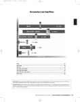
2.5.1 Energotester's block diagram is shown in Fig. 2.1.
Fig 2.1 Block Diagram
SCU— Unit of Scaling Converters of voltage (SCU) and current (SCI); ADCU— Unit of Analog-to-Digital
Converters of voltage (ADCU) and current (ADCI); D — Data Display Unit (graphical display and
keyboard); MU — Memory Unit; PCC — PC Connection Unit; GPS — GPS receiver; DPB— Data
Processing Block; FAMU, FAMI — "Former of Array" Modules; CMUrms, CMIrms — Calculating Modules
for RMS values, M P,Q,S — Module calculating active, reactive and apparent power; FFTMU, FFTMI —
Fast Fourier Transform Modules
2.5.2 Energotester shares basic principles of Analog-to-Digital Conversion (ADC) and the
Sampling Method. In the SCU, three-phase input voltages and currents are converted into 5V level
voltage signals compliant with ADCU and ADCI measuring ranges. Instantaneous signal values are
converted into digital codes by six ADCs and routed to the DPB. In the DPB, the arrays of sampled
instantaneous values of voltage (Uuj) and current (Uij) are created (j is the number of a sample).
Programmatically calculated values of measured parameters are shown on the Data Display, stored in
the Memory Unit and may be transferred to a PC, if necessary.
Energotester can determine all of the AC network parameters simultaneously: current, voltage,
frequency, phase angles, individual harmonic current and voltage components (n from 1 to 50), active,
reactive and apparent power.
2.5.3. The Unit of Scaling Converters includes clamp-on CTs (or instrument current transformers
– 3 pcs) each one individually calibrated (electronically compensated) to match a certain measuring
channel, and three voltage dividers. SCU relays are processor-controlled. The processor issues the
commands (in the form of a potential) to switch over voltage inputs. The controller outputs the value
of an active measuring range on the graphical display. The relays serve to switch among voltage
measuring ranges for the input transformers.
2.5.4 The ADC Unit has 6 identical channels. They operate independently converting ± 5V
analogue input signals into 24-bit binary data. Each channel includes two chips: an input amplifier and
ADC itself. Type AD8656 chip, the input amplifier, matches the scaling converters due to its low
output voltage drift, negligible temperature drift, and ultra-low input currents. Channel’s input
18
МС2.725.003-01 UM
impedance is over 50 MOhm. Signal taken from the amplifier is fed into the ADC chip. The latter
performs complete 24-bit conversion without signal quality degradation, and transmits the result in
serial code to the controller upon request. As to the entire Measuring board, it takes voltages applied
to the measuring inputs, digitizes them, and passes the results onto the Processor board.
2.5.5 Data Processing Block, otherwise called the Processor board or the Controller board,
exercises full control over Energotester. It is responsible for making calculations over the arrays of
digitized samplings, storing the results in non-volatile memory and displaying them on LCD screen,
counting time, marking the intervals as per real-time clock, exchanging data with external devices
(PCs), and receiving commands and data from operator’s keyboard. The Controller board bears the
ultimate responsibility for smooth operation of the entire instrument. At the heart of the Controller is a
Texas Instruments dual-core signal processor. Such a solution makes possible prompt upgrading of the
firmware, keeping the hardware intact.
Data from ADC are processed programmatically and shown on Data Display. Calculations over
sampled data are based on ADC readings taken over 0.2 sec (800 samples per period are taken at 50
Hz frequency). Actual values are recalculated and displayed every 3 s.
2.5.6 Memory Unit provides storage space for measurement results, settings, etc.
2.5.7 Power Supply Unit generates voltages for the Processor and Measuring boards
2.5.8 Graphical LCD Display and operator's membrane keyboard are both mounted on the
Device's front panel and connected to the Processor Board. The keyboard is used to select operation
and display modes, configure the Device etc.
2.5.9 GPS receiver provides for high-accuracy synchronization with international time scale
UTC which makes it possible to apply IEC 61000-4-30 (class A) measurement procedures and
flagging concept.
19
MARS-ENERGO
3 Preparing for operation
3.1. Operating restrictions
If Energotester has been moved from a cold environment (with ambient temperature below -5°
C) into a warm one, it shall be left to stand for at least 4 hours at room temperature before applying
power, to make sure that no condensation remains inside. In case of a drop in ambient temperature for
10° C or more, Energotester shall be kept for at least 30 minutes under operating conditions not
connected to power.
Note! Energotester must not be used under the ingress of moisture inside its body.
The contrast of LCD screen image can be impaired under the temperature below –10 ° C.
However, this does not affect the performance.
3.2 Unpacking
Check that the delivery package contains all parts specified in the Supply Agreement. Check to
see if the manufacturer’s seal is intact. Should anything in the package be found damaged, contact the
supplier immediately.
The delivery package is specified in Table 2.1.
Unpack the instrument, unscrew the cover of the battery compartment and insert 4 batteries
provided in the delivery package considering their polarity.
3.3 Preparing for operation
3.3.1 Controls and Connectors
Controls and connectors are listed in Table 3.1.
Table 3.1
Key
0...9
⇓⇑
⇐⇒
`ENT`
'ESC'
`F`
'ON'
20
Name and Function
Numeric keypad: Press to type in numeric values
Up and down arrow keys: press to scroll through various menu items or data fields;
Press to increase or decrease a value by 1 in the "value entry" mode
Left and right arrow keys: Press to scroll through various menu items or data fields
Enter: Press to activate a menu item, enter data, enable a selected mode,
or insert a symbol while entering a name
Escape: Press to exit a mode or leave some current menu item for an upper level menu
Function: press as a hot key to exit from any menu item and enable "Connections and
ranges" mode
Press (3 quick strokes) to turn on the Instrument,
Press and hold to turn the instrument off.
МС2.725.003-01 UM
Energotester's upper panel is shown in Fig. 3.1.
Fig. 3.1 Upper panel
UA (UL1), UB (UL2), UC (UL3), UN — plugholes for connection to phase voltages and neutral;
"Current" — connector for connection to input current converters (current clamps).
Front and rear panels are shown in Fig. 3.2.
1
2
3
4
5
6
7
Fig. 3.2. Front and rear panels
1 — Keyboard; 2 — Power Supply connector; 3 — USB port for connection to a PC; 4 — Graphic
display; 5 — GPS antenna connector; 6 — Seal; 7 — Battery compartment
21
MARS-ENERGO
3.3.2 Turning on / off
The symbol ! placed on the front panel is intended to alert the user to the presence of the
important operating instructions listed below. Warning notices are used in the text as follows: NOTE:
[important information on the topic discussed in a given section or paragraph]; Caution! [Affects
equipment – if not followed may cause damage to the Device]; Warning! [Affects personnel safety – if
not followed may cause bodily injury or death.]
Warning! To avoid electric shock, it is strongly recommended to connect (disconnect) the
Instrument to the measured circuits when they are de-energized. Otherwise, connection
(disconnection) to the measured circuits shall be carried out by qualified service personnel in
compliance with local safety regulations in force.
Caution! Current clamps must not be connected to DC circuits.
Clips of measuring cables and current clamps shall be connected to Energotester first, BEFORE
being attached to the powered contacts or live conductors of the circuit to be measured.
Caution! It is strongly recommended that jaw faces of current clamps be kept clean and free
from any dirt or oxidizing, to ensure the jaws are fully closed. If there is a tight clearance between the
clamped jaws, the measurement accuracy may be considerably impaired.
Caution! You must not connect Energotester to mains via Power Adapter if expendable (nonrechargeable) AA batteries are inside its battery compartment instead of rechargeable batteries
(accumulators).
Note! The number of charge cycles of the accumulators is limited and substantially determined
by their quality and operating conditions.
Power Energotester from mains in the following order:
Connect "12.6 V" output of the Power Adapter to “DC 12.6 V” input of the Instrument (see
Fig. 3.2);
Plug the mains cable of the Power Adapter to mains socket.
Press ON button three times to turn on the Instrument.
Voltage circuits have three plugholes UA (UL1), UB (UL2), UC (UL3) for phase voltages, one more
plughole UN for connection to neutral, and one connector for phase currents IA (IL1), IB (IL2), IC (IL3).
Galvanic isolation among the current circuits is provided by current clamps. The voltage circuits are
symmetrical and have one common point (neutral conductor). Use manufacturer-supplied cables only.
Inspect the cables. Ensure all joints are made properly to avoid overheating and excessively high
resistance. A multitude of Energotester's connections are pictured in Appendices A and B.
Note: When Energotester is powered by the accumulators (without mains supply), time of its
continuous operation depends on the number of charge cycles. With 2700mA*h Ni-Mh batteries,
Energotester is operational for at least 2 hours after one 4.5 hour charge cycle
Note! When Energotester is turned on for the first time, it is recommended to make it run into
shutdown without mains supply (to full discharge of the batteries). Then connect Energotester to mains
supply via Power Adapter and fully charge the batteries (battery condition indicator will be displayed
in green), see section 4.1.2.
After applying power and performing self-test and initialization during a few seconds,
Energotester goes to the initial configuration mode. During the initialization, performance of every
unit is checked and signal processing and calculation programs are loaded (Fig. 3.3).
22
МС2.725.003-01 UM
Fig 3.3 "Loading..." screen
At the conclusion of the load procedure, Energotester goes to the password entry mode
(Fig.4.1.1) and becomes operational immediately after entering a correct password. To ensure that its
metrological characteristics are as specified in Table 2.2, Energotester shall be kept powered for at
least 5 minutes.
The display shows: Manufacturer's logo, current date and time, circuit connection type and
various status symbols (battery charge level etc.) in the upper line, as well as measuring range and
some other status symbols in the lower line. The status symbols are described in section 4.1 (Operator
interface).
To turn off Energotester, press and hold ON key for 2 s, or select the "Shut down" option from
the Main menu. The latter option also allows the user to restart the Instrument via "Password entry"
screen.
Fig. 3.4 "Shut down / Restart" screen
23
MARS-ENERGO
4. Operation
4.1 Operator Interface
4.1.1 Passwords
After applying power and performing self-test, initialization and program loading procedures,
Energotester goes to the password entry mode (Fig. 4.1.1). User access within the Instrument may be
granted at two levels. The access level determines the set of options available within the “Settings”
menu (see section 4.4.1). Both 1st and 2nd level passwords must contain 10 digits.
Fig. 4.1.1 Password entry screen
The following passwords are factory preset:
2nd level password – 2222222222;
1st level password – 0000000000.
Password entry is finished by pressing ENT.
4.1.2 Status symbols
Operator interface was designed on the model of nested menus. Keys `ENT`, `ESC`, ⇓, ⇑, ⇐,
and ⇒ are used to navigate to a desired menu item. Location and functions of the controls and
indicators are given in Fig. 3.2 and Table 3.1.
Regardless of the mode, the top status line displays (Fig. 4.1.2):
Actual date and time
Power supply mode and charge level of the accumulators ("AC power plug" and "Battery"
symbols)
Three symbols
indicate PC connection and GPS receiver states:
— PC connection on/off,
— USB connection on/off,
— wireless (WLAN)
connection on / off.
The third ("Satellite") symbol is described in detail in sections devoted to time settings and GPS
diagnostics.
24
МС2.725.003-01 UM
Fig. 4.1.2 Top status line
Fig. 4.1.3 Bottom status line
The bottom status line (Fig. 4.1.3) displays:
Circuit connection scheme (the leftmost symbol);
Voltage and current measurement ranges (the range value displayed in red means that the
input signal is applied via instrument transformers) and type of input current converters:
c — current clamps
t — Current Transformer Block
f — flexible current clamps;
Nominal frequency;
Phase rotation indicator( ) L (red)— reversed; R (grey)— not determined; R (green)—
correct;
Synchronization with measured voltage:
Grey — no synchronization
Yellow — synchronization with phase L1 (A) or line L1L2 (AB)
Green — synchronization with phase L2 (B) or line L2L3 (BC)
Red — synchronization with phase L3 (C) or line L3L1 (CA);
Actual status of logging mode (black square - no logging; circle - logging is active; red circle
- an actual logging session was not interrupted; yellow circle - an actual logging session was
interrupted).
An hourglass (the rightmost symbol) appears for a short time while Energotester is being
reconfigured e.g. after changing its circuit connection scheme. In the presence of this symbol, the user
is allowed to navigate through screens / menu items. The indication of the delay only relates to
measurement processes. Operation mode is indicated by "3s" indicator (blinking from red to white
means updating of 3s averages).
Voltage measurement ranges are available as 10V, 60V and 240V.
Measuring range and circuit connection options are available via the “Settings” menu. In
addition, the Measuring range selection function may be called up promptly from no matter what menu
or item, just by pressing `F` hotkey.
25
MARS-ENERGO
4.1.3 Main menu
On entering the correct password, Energotester takes you to the “Main menu” window. Main
menu items correspond to basic operation modes and settings (Fig.4.1.4).
Fig. 4.1.4 Main menu
Use ⇓, ⇑ keys to select an item, and `ENT` key to enter the selected mode.
Note: The operator interface may be modified with respect to the order of displaying
information. However, the changes do not affect metrological and technical characteristics of the
Instrument.
4.2 Measurements
The “Measurements” screen is shown in Fig. 4.2.1.
Fig. 4.2.1 "Measurements" menu
CAUTION ! Before making any measurements, set the Instrument up for nominal phase voltage,
phase current and circuit connection scheme you want to measure and select voltage connection type
and CT type (if applicable). Press 'F' key to open the corresponding screen.
The "Measurements" menu contains nine options, the use and selection of which is dependent on
user need: power; current and voltage; harmonics; phase angles; etc. Press ⇓ or ⇑ to cycle through
menu options. Press 'ENT' to enable an option, press 'ESC' to return to the Main Menu
26
МС2.725.003-01 UM
Except for “Waveforms”, measurement modes specified in the menu show “real time”
parameters on their respective screens. On-screen data are updated each 3 seconds.
Note!
For all measurement screens:
Indication of phase parameters: Ua, Ub, Uc, Ia, etc.
Indication of phase-to-phase parameters: Uab, Ubc, Uca, Iab etc.
4.2.1 Measuring currents and voltages
In the "Voltage and Current" measuring mode, 4 screens are available. The screens are cycled
with ⇐, ⇒ keys. The screens are shown in Fig. 4.2.2 (three phase 4-wire connection).
Energotester displays measured values of voltage, current and power considering scaling factors
(turns ratios) selected in the corresponding items of the "Connections and Ranges" menu (called up by
pressing 'F' hotkey): "Voltage connection", "VT type" and "CT type". In particular, if Energotester is
connected to the object under review via voltage and/or current instrument transformers (namely to the
VT and/or CT secondary windings), it displays measurement results considering transformer ratios. To
display primary currents, voltages and power values, it is necessary to select proper types and
parameters of CTs and VTs.
Use `ESC` key to return to the main menu.
Fig. 4.2.2. "Voltage and Current" screen for three-phase 4-wire connection
Three-phase 4-wire connection
Values displayed:
RMS of phase and phase-to-phase voltages and currents;
Average-rectified values of phase voltages and currents;
Average values (DC component) of phase voltages.
27
MARS-ENERGO
Three-phase 3-wire connection
Values displayed:
RMS of phase currents and RMS of phase-to-phase voltages;
Average-rectified values of phase currents.
Single-phase 2-wire connection
Values displayed:
RMS of current and voltage;
Average-rectified values of current and voltage;
Average value of voltage UDC (DC component).
If a signal has no AC voltage component, its average voltage value UDC (DC component) equals
DC voltage supplied.
Note: Physically speaking, the effective (root mean square or RMS) values of voltage and current relate to power
(heat energy) dissipated through an active load (e.g., a bulb or a water heater),
2
2
R
R = I RMS
P = U RMS I RMS = U RMS
Where:
IRMS, URMS are the effective (root mean square) values of voltage and current;
P is the active power dissipated through an active load;
R is the active load resistance.
The algorithm of RMS voltage (current) calculation may be simplistically phrased as follows: instantaneous voltage
(current) values measured by the ADC are squared and averaged, and then the square root is extracted.
Average voltage (current) value is calculated from the weighted sum of voltage (current) instantaneous samples. The
sign is determined by the DC component.
Certain physical quantities (e.g. the magnetic force of attraction between a solenoid and a core) are proportional to
the average-rectified values of voltage (current). The algorithm of Average-rectified voltage (current) value calculation
may be simplistically described as averaging over the weighted sum of instantaneous samples coming from the ADC. All
voltage (current) samples are considered positive.
In case of DC voltage (current), its RMS, Average and Average-rectified values are equal in magnitude.
For a pure sinusoidal signal, the average value equals zero; the RMS and average-rectified values are related by a
constant factor.
If a signal is not sinusoidal, its RMS, Average, and Average-Rectified values may differ.
Let’s consider rectangular pulses with 10 V amplitude and pulse period-to-pulse duration ratio of 10.
RMS voltage value for such a pulse train would be:
U RMS =
28
10 2 V
≈ 3.16V
10
МС2.725.003-01 UM
Average and Average-Rectified voltage values are:
U average = U average-rectified =
10V
= 1V
10
When this voltage is applied to an 1 Ohm resistor, the power dissipated in the resistor would be:
P = U RMS I RMS = 3.16 ⋅ 3.16 ≈ 10 W
There are a number of RMS-scaled instruments that actually measure average-rectified values of voltage (current),
e.g. the instruments based on an electrodynamic measuring principle. It is important to consider that such instruments
display correct values of voltage (current) only in case of a pure sinusoidal signal.
Caution! The screen line showing average values of current is informative for technical service
personnel only, considering that DC current component cannot pass through input transformers and
current clamps.
4.2.2 Measuring phase angles
In the "Phasors" mode, the display shows: phase angles between 1st voltage harmonics and
phase angles between 1st voltage and current harmonics. Phase angles in degrees are put in column on
the left part of the screen; the right display area shows a vector diagram. The vector diagram reflects
the same phase relations, with long vectors being voltages, and shorter vectors standing for currents
(Fig. 4.2.6).
∧
∧
To check phase rotation for a three-phase system, make sure that angles U A(1) U B (1) , U B (1) U C (1) ,
∧
U C (1) U A(1) are positive (clockwise rotation).
Press `ESC` key to return to the previous mode.
Fig. 4.2.3 “Phasors” screen for different circuit connections
29
MARS-ENERGO
Three-phase 4-wire connection
Values displayed:
Phase angles between 1st harmonics of phase voltages
Phase angles between 1st voltage and current harmonics per each phase.
Three-phase 3-wire connections
Values displayed:
Phase angles between 1st harmonics of phase-to-phase voltages
Phase angles between 1st harmonics of phase-to-phase voltages and 1st harmonics of phase
currents.
Single phase 2-wire circuit connection
The screen displays phase angle between the 1st harmonics of current and voltage.
Caution! Each time the RMS value of voltage or current is found less than 1 % of its nominal
range, no parameters in “Phase Angles” mode are calculated. Instead, angles between voltages are
displayed as ~ 90°, and angles between voltages and currents are displayed as ~ - 90°.
4.2.3 Measuring Power Quality Parameters
Selecting "Power Quality Parameters" option from the Main menu will take you into a set of 6
screens (Fig. 4.2.4) linked in a chain (use ⇐, ⇒ to browse through the screens). These screens make it
possible to view all power quality parameters measured by Energotester.
Press 'ESC' to return from the "Power Quality Parameters" mode to the Measurements menu.
PQP being measured are displayed with or without logging.
Data are updated in intervals equal to averaging times stated in EN 50160 standard for
corresponding power quality parameters.
Other parameters are updated each 3 seconds.
Flicker measurement procedure starts on opening the Voltage Flicker window. The first
measured Pst value appears on the “real-time” screen with 10-minute delay which corresponds to the
Flicker observation period. Then Pst values are updated each 2 hours.
30
МС2.725.003-01 UM
Fig. 4.2.4 View of PQP screens
31
MARS-ENERGO
4.2.4 Measuring power
The Power screen displays the following power-related parameters:
Active power;
Reactive Power;
Apparent power;
Power factor.
Fig. 4.2.5 "Power" screen for
three-phase 4-wire connection
Three-phase 4-wire connection
Values displayed:
Per phase and total active, reactive and apparent power:
Active power P,
Apparent power S,
Q1 — Reactive power of fundamental harmonic.
In addition, the screen displays:
Power factor per each phase.
Three-phase 3-wire connection
Values displayed:
Total values of active, reactive and apparent power:
Active power P,
Apparent power S,
Q1 — Reactive power of fundamental harmonic.
In addition, the screen displays:
Total power factor.
Single-phase 2-wire connection
Values displayed:
Values of active, reactive and apparent power:
Active power P,
Apparent power S,
Q1 — Reactive power of fundamental harmonic.
In addition, the screen displays:
Power factor.
Notes on reactive power:
Reactive power can be calculated by geometrical, phase-shift, or cross-connection methods.
32
МС2.725.003-01 UM
When calculation of reactive power values follows the phase shift method, instantaneous voltage
value is multiplied by instantaneous current value displaced in phase by 90°. The method of crossconnection takes the product of instantaneous value of phase current, and the instantaneous value of
line voltage.
In theory, if a three-phase system is symmetrical and free of non-linear distortions, the reactive
power would be of the same value, regardless of the calculation method. When the symmetry is broken
within the system of voltage vectors (UАВ ≠ UВС ≠ UСА), the reactive power calculated with crossconnection method turns out different from what the other two methods give. Non-linear distortion
makes the power calculated with geometrical method differ from the other two. Thus, under real
conditions the three values of reactive power are never precisely the same.
Regular power system is typically equipped with reactive power meters of a certain type (e.g., in
Russia meters operating on the principle of cross-connection are used in three-phase systems; meters
based on phase shift method are typical for single-phase systems). Thus, when testing a meter, its
principle of operation should be taken into account.
Caution! Each time the RMS value of voltage or current is found less than 1 % of its nominal
range, the reactive power is not calculated with phase shift method: zeroes (0) are displayed instead of
a measured value.
Notes on power factor:
For pure sinusoidal signal, active, reactive and apparent powers are computed from the formulae:
P = U RMS I RMS cos ϕ ,
Q = U RMS I RMS sin ϕ ,
S = U RMS I RMS , ,
where
IRMS, URMS are effective (root mean square) values of voltage and current;
ϕ is phase angle between current and voltage.
Power factor can be expressed as:
PF = P S
For a perfect sinusoidal signal:
cos ϕ
P U I
PF = = RMS RMS
= cos ϕ
S
U RMS I RMS
By definition, the PF is a number between 1 and -1 (letters L or C stand for load type: L –
inductive; C – capacitive, e.g. 0.52L, 0.83C, -0.92C). Although PF is directly concerned with phase
angle between current and voltage, there may be a case (e.g. in the presence of severe signal distortion
in a current circuit), that PF < 1 at zero phase shift between current and voltage ( ϕ = 0 , cos ϕ = 1 ). The
more current and voltage curves differ from pure sine, the more K P differs from cos φ.
Power Factor is basically determined by the type of loads
U
I
I
U
connected to the system (inductive or capacitive). If current lags
ϕ
−ϕ
voltage (phase angle between current and voltage is positive),
the load is inductive. If current leads voltage (phase angle
between current and voltage is negative), the load is capacitive.
The current vector may be in one of 4 quadrants relative to the voltage vector.
33
MARS-ENERGO
Interval
Quadrant
Angle between current
and voltage
Active power
Reactive Power
I
0° to 90°
URMSIRMS to 0
0 to URMSIRMS
Inductive
II
90° to 180°
0 to –URMSIRMS
URMSIRMS to 0
Capacitive
(negative)
III
180° to 270°
(–180° to –90°)
–URMSIRMS to 0
0 to –URMSIRMS
Inductive
(negative)
IV
270° to 360°
(–90° to 0°)
0 to URMSIRMS
–URMSIRMS to 0
Capacitive
Load type
Positive active power (energy) relates to energy import, negative active power (energy)
corresponds to energy export. Positive reactive power (energy) indicates an inductive load with
energy import, or a capacitive load with energy export.
Note: To measure apparent power consumed by a current instrument transformer load, use
Un=10V.
4.2.5 Measuring frequency and frequency deviation
Fig. 4.2.6 "Frequency and frequency deviation" screen
The screen displays measured values of frequency and frequency deviation.
Press `ESC` key to return to the previous mode.
4.2.6 Measuring harmonics and interharmonics
In the "Harmonics" mode, the following screens are available:
34
МС2.725.003-01 UM
Fig. 4.2.7 "Harmonics and Interharmonics"
options
"RMS values" option on both screens will take the user into a set of screens (use ⇐, ⇒ keys to
browse through the screens). Number and contents of the screens depend on circuit connection scheme.
Keys ⇓, ⇑ are used to scroll up and down to see all of 50 harmonics.
For "Harmonic subgroups" the displayed parameters are as follows:
RMS values of U and I harmonics up to 50 (including THD and maximum values);
Coefficients - U and I harmonics from 2 to 50 with respect to the 1st harmonic in % (including
THD and maximum values)
Diagrams;
K-factor.
Maximum values of harmonic or interharmonic components can be set to zero by pressing
numeric key "0".
"RMS values" screens related to "Interharmonic groups" look in the same way.
35
MARS-ENERGO
Fig. 4.2.8. Typical "RMS Values" screens
("Harmonic subgroups" and "Interharmonic groups" options)
Fig. 4.2.9 Typical "Coefficients" screens ("Harmonic subgroups" menu)
Fig. 4.2.10 "Diagrams" screen ("Harmonic subgroups" menu)
36
МС2.725.003-01 UM
Fig. 4.2.11 "Diagrams" screens ("Interharmonic groups" menu)
Fig. 4.2.12 “K-factor” screen ("Harmonic subgroups" menu)
Note: Each time the RMS value of voltage or current is found less than 1 % of its nominal range,
the Harmonics mode related parameters are not calculated: zeroes (0) are displayed instead of
measured values.
Notes on K-factor:
Presence of high-order harmonics of current and voltage in electric circuits create a major problem either for the
circuits or for the connected equipment. For example, higher harmonic currents passing through the transformers
considerably impair their characteristics being responsible (among other things) for transformer heating and magnetic
flux losses. Moreover, conventional transformers can even become dangerous under severe non-linear load conditions.
K-factor is one of the parameters used to estimate non-linear load characteristics in electric circuits. K-factor =1
indicates a linear load in the circuit (no harmonics).
Regarding the transformers, the K-factor rating is used by transformer designers to reflect the ability of the
transformer to withstand harmonic content while operating within the temperature range specified for its insulation
system (typically, K-factor is given in the transformer’s technical specifications). The higher the transformer K-factor,
the greater is its resistance to non-linear distortion conditions.
The algorithm used to calculate K-factor is:
34
K=
∑ (i
h =1
h
⋅ h) 2
, where:
34
∑i
h =1
2
h
ih – rms value of h-order harmonic current passing through a load;
h - harmonic order.
K-factors for some typical loads:
Welders: К=4
UPS without input filtering: К=13
Motor drives: К=20
37
MARS-ENERGO
4.2.7 Waveforms
In the “Waveforms” mode, Energotester plots voltage and current waveforms on its display (Fig.
4.2.13). On entering the mode, the display shows “phase A” voltage waveform. By pressing number
keys `1`, `2`, `3`, `4`, `5`, `6` the user can make visible or hide other waveforms (Ua, Ub, Uc, Ia, Ib,
and Ic respectively). In addition, maximal amplitude values for all current and voltage curves being
displayed are shown in the upper part of the screen. Waveforms are updated each 3 s.
Press `ESC` key to return to the previous mode.
Fig. 4.2.13 “Waveforms” screen
4.2.8 Events
In the "Events" menu the user can specify thresholds for three types of events to be recorded in
the memory, namely:
Voltage dips;
Voltage swells;
Voltage interruptions.
"Events" options are shown in Fig. 4.2.14.
Fig. 4.2.14 "Event type" selection screen
38
МС2.725.003-01 UM
On selecting the event type, Energotester opens one of the screens pictured below.
Fig. 4.2.15 "Events" screens
4.2.9 Measuring energy
In the "Energy" measurement mode, 2 options are available:
Fig. 4.2.16 "Energy measurement type" selection screen
On selecting the "Progressive total" option, time count and energy measurement start
automatically. The screen displays:
Time count in minutes and seconds;
Cumulative total values of active (kW∙h) and reactive (kvar∙h) energy.
39
MARS-ENERGO
Energy is measured continuously. Energy measurements start on turning on the Instrument
and stop on turning it off, or on changing the basic settings, e.g., circuit connection scheme,
ranges and the like. The energy is measured for all phases in total and displayed separately for
export and import directions. In this mode, Energotester calculates energy usage like an
electric energy meter.
The mode is controlled with "1" and "2" numeric keys (reset and stop functions respectively).
Fig. 4.2.17 "Energy" screens
Note: It is recommended to carry out energy measurements as for on-peak load so also for offpeak load periods.
"Half-hourly" measurements start on XX:00 min or XX:30 min after entering the "Half-hourly"
option (e.g., if you enter the mode on 17:45, the measurements will start on 18:00, entering the mode
on 18:07 means that the measurements will start on 18:30). Measurement results are recorded
(updated) each 30 min. Each reading is an energy value calculated for the half-hour period from the
latest update. Multiplied by 2, the energy reading equals the average value of power (kW, kVar)
obtained for the corresponding 30 min.
4.2.10 Synchronized measurements
In the "Synchronized measurements" mode, the display shows: Start time of a measurement,
measurement duration (in periods) and measurement results.
Start time of measurements should be set at least 30 s later than the present time.
Other restrictions applied to measurement start time and duration settings are as follows: the
start time should be a multiple of 10 min (e.g. 16:10, 17:20 etc) and the measurement duration
should be a multiple of 10 (e.g. 150 periods, 160 periods etc).
40
МС2.725.003-01 UM
Fig. 4.2.18 Screens used to set up, enable and view synchronized measurements
The 4th screen displays changing of Start measurement time (the cursor is highlighted in red).
Fig 4.2.19 "Error setting" message
41
MARS-ENERGO
Synchronization chart
4.2.11 “Save actual measurements”
On selecting the item, the values of all measured parameters (averaged over 3 s) are recorded into
the internal memory for one time.
4.3 Logging of PQP
4.3.1 Introduction. Applying
Energotester's design versions for power quality monitoring and analysis
Energotester PQP-A-AX(-SX) comes in 3 design versions with regard to sets of measured PQP
(see Table 1).
Each set can be used for particular purposes:
1 — AC power certification (testing of compliance with EN 50160: 2010 requirements), PQP
monitoring. The following parameters are monitored and registered:
δU(−) and δU(+) — under- and overdeviation of power supply voltage, % UN;
δf — frequency deviation, Hz.
In addition, all of the parameters defined by EN 50160: 2010 (excluding Flicker values) along with
events and their data (not standardized) are monitored and documented. Option used for AC power
certification purposes (IEC 61000-4-30 class A measurements): Energotester PQP-A-A1.
2 — Regular power quality inspection and AC power certification (testing of compliance with EN
50160: 2010 requirements). All EN 50160: 2010 parameters are documented excluding events (not
registered). Option used for AC power certification purposes (IEC 61000-4-30 class A measurements):
42
МС2.725.003-01 UM
Energotester PQP-A-A2. Option intended for regular power quality inspection (IEC 61000-4-30 class S
measurements): Energotester PQP-A-S2.
3 — Used to record all power supply voltage changes defined and described in EN 50160: 2010.
Option used for AC power certification purposes (IEC 61000-4-30 class A measurements):
Energotester PQP-A-A3.
Complete with clamp-on current sensors (clamps), Energotester can be used to:
Carry out power quality analysis (determine distortion factors),
Build consumer load graphs,
Test automatic meter reading systems,
Detect sources of energy losses.
4.3.2 Logging options
Functions of measuring and viewing of power quality parameters as well as recording of
averaged values of electric quantities into the non-volatile memory (logging mode) are enabled from
the “Power Quality Logger” main menu option (Fig. 4.3.1).
Fig. 4.3.1 "Power Quality Logger"
options
"Power Quality Logger" menu has 10 options selectable with ⇓, ⇑ keys. Press `ENT` to select a
mode or `ESC` to return to the menu. On entering the selected menu option, a selection and/or editing
window for the parameter will appear.
Following the list of logging settings, the screen displays START LOGGER or STOP LOGGER
commands. The command active at the moment is visible (see the 3rd screen in Fig. 4.3.1). In other
43
MARS-ENERGO
words, when logging is in progress the screen shows STOP LOGGING command, and a "red circle"
indicator is displayed in the bottom line.
4.3.3 Selecting site name
The site name ("Installation name") option is used to specify identification fields that will be
represented in the test report. Energotester saves the current name of installation under review in the
memory and stores 10 names used earlier. The "Installation name" option of POWER QUALITY
LOGGER menu gives access to this data.
Fig. 4.3.2 shows the selection and editing windows used to create a new site (installation) name.
This is done by replacing characters in the current name field.
Fig. 4.3.2 Site name selection and entry windows
On entering the “Installation name” editing mode, the currently active installation name is
displayed in NEW NAME field. The editing procedure implies replacing characters (selected by the
cursor in the form of character’s red highlight) in this NEW NAME line.
At every step, a character in the current name line highlighted in red with upper cursor is
replaced. You can move this cursor along the NEW NAME line with commands
(located in the
bottom line of the Character Table). To do this, place the lower “Character Table” cursor on one of
these commands and press ENT.
On selecting the character to be replaced, position the cursor on the Character Table, select the
desired character using arrow keys and press ENT. On doing this, the old character in the NEW
NAME line is replaced with a new one, and the cursor will appear on the next character position. It is
possible to go to the lower case mode (only once while editing one name). To do this, select
field and press ENT.
Position the upper cursor (located in the NEW NAME line) on the next character to be replaced
and repeat the procedure. Then press ENT.
At the end of the procedure, place the cursor on
command and press the ENT key to
record the new name into the memory. Energotester will open the screen shown in Fig. 4.3.2 on the left
with the new name in the current name line. Press ESC to return to the "Power Quality Logger" screen.
Ten last used installation names are stored in the memory and can be selected from the "10 Lastused" menu.
44
МС2.725.003-01 UM
4.3.4 Selecting declared voltage
Fig. 4.3.4 Declared voltage selection screen
The screen is called up by selecting its name in the "Power Quality Logger" menu.
The default declared voltage can be edited with the right/left arrow keys and numeric keys. Press
ENT to open the editing window. The new value is confirmed by pressing ENT. Conditions of the
logging session will be changed at this moment.
Please note that the new declared voltage value can only be selected within the frames outlined
with min. and max. thresholds.
4.3.5 Supply system
The menu is used to select the type of power supply system under review. Power supply system
type determines how the results will be calculated.
Fig. 4.3.5 Supply system selection screen
4.3.6 PQ threshold sets
"PQ threshold sets" option contains sets of PQ thresholds (standard sets are listed in Table
4.3.1). Power Quality Parameters are measured and calculated on this basis. The PQ threshold
selection window contains six options. Four of them correspond to four GOST 32144-2013 (EN
50160: 2010) points related to standard nominal voltages of the network under review, as measured at
the probe connection point. Two more sets of PQ thresholds are customer-defined.
Settings of all types are stored in the internal memory, each one in two variant records: for single
phase / three-phase 4-wire and three-phase 3-wire networks. Selection of a variant is made automatically
according to the circuit connection type specified on the “Circuit connection” screen. By default, the
45
MARS-ENERGO
custom settings are set to 0.38 kV values. Use ⇓ or ⇑ keys to select the type of settings. Press ‘ENT’ to
activate the new set or ‘ESC’ to reject. Either of these actions will bring up the "Power Quality Logger"
window. The user can create and maintain the custom settings either on a PC (“Network
Energomonitoring” program) or via “PQ threshold sets” → ”Custom Threshold Sets 1” and “Custom
Threshold Sets 2” menu. Frequency deviation can take positive and negative values, other parameters are
always positive. The GOST 32144-2013 (EN 50160) standard settings cannot be changed. When using
instrument transformers to connect to a 6-25 kV, 35 kV, or 110-220 kV network, Energotester nominal
voltage is set so as to fit secondary voltage of the instrument transformers to let the logged results be
recalculated considering transformer ratio. While using PC “Network Energomonitoring” program to
process logged results, be sure to declare the transformer(s) by entering the actual transformer ratio in an
appropriate dialog box (see Network Energomonitoring program, User Manual).
Fig. 4.3.6 Sets of custom PQ thresholds
46
Table 4.3.1
Standard settings according to GOST R 54149-2010
Order
Total
2
3
4
5
6
7
8
9
10
11
12
13
14
15
16
17
18
19
20
21
22
23
24
25
26
27
28
29
30
31
32
95% of time
0.38 kV
8.00
2.00
5.00
1.00
6.00
0.50
5.00
0.50
1.50
0.50
3.50
0.20
3.00
0.20
0.30
0.20
2.00
0.20
1.50
0.20
0.20
0.20
1.50
0.20
1.50
0.20
0.20
0.20
not defined
0.20
not defined
0.20
6—25 kV
5.00
1.50
3.00
0.70
4.00
0.30
3.00
0.30
1.00
0.30
2.00
0.20
2.00
0.20
0.30
0.20
1.50
0.20
1.00
0.20
0.20
0.20
1.00
0.20
1.00
0.20
0.20
0.20
not defined
0.20
not defined
0.20
35 kV
4.00
1.00
3.00
0.50
3.00
0.30
2.50
0.30
1.00
0.30
2.00
0.20
1.50
0.20
0.30
0.20
1.00
0.20
1.00
0.20
0.20
0.20
1.00
0.20
1.00
0.20
0.20
0.20
not defined
0.20
not defined
0.20
110—220 kV
2.00
0.50
1.50
0.30
1.50
0.20
1.00
0.20
0.40
0.20
1.00
0.20
0.70
not defined
0.20
not defined
0.50
not defined
0.40
not defined
0.20
not defined
0.40
not defined
0.40
not defined
0.20
not defined
not defined
not defined
not defined
not defined
100% of time
0.38 kV
12.00
3.00
7.50
1.50
9.00
0.75
7.50
0.75
2.25
0.75
5.25
0.30
4.50
0.30
0.45
0.30
3.00
0.30
2.25
0.30
0.30
0.30
2.25
0.30
2.25
0.30
0.30
0.30
not defined
0.30
not defined
0.30
6—25 kV
8.00
2.25
4.50
1.05
6.00
0.45
4.50
0.45
1.50
0.45
3.00
0.30
3.00
0.30
0.45
0.30
2.25
0.30
1.50
0.30
0.30
0.30
1.50
0.30
1.50
0.30
0.30
0.30
not defined
0.30
not defined
0.30
35 kV
6.00
1.50
4.50
0.75
4.50
0.45
3.75
0.45
1.50
0.45
3.00
0.30
2.25
0.30
0.45
0.30
1.50
0.30
1.50
0.30
0.30
0.30
1.50
0.30
1.50
0.30
0.30
0.30
not defined
0.30
not defined
0.30
110—220 kV
3.00
0.75
2.25
0.45
2.25
0.30
1.50
0.30
0.60
0.30
1.50
0.30
1.05
not defined
0.30
not defined
0.75
not defined
0.60
not defined
0.30
not defined
0.60
not defined
0.60
not defined
0.30
not defined
not defined
not defined
not defined
not defined
33
34
35
36
37
38
39
40
41
42
43
44
45
46
47
48
49
50
0.20
0.20
not defined
0.20
not defined
0.20
0.20
0.20
not defined
0.20
not defined
0.20
0.20
0.20
not defined
0.20
not defined
0.20
0.20
0.20
not defined
0.20
not defined
0.20
0.20
0.20
not defined
0.20
not defined
0.20
0.20
0.20
not defined
0.20
not defined
0.20
0.20
0.20
not defined
0.20
not defined
0.20
0.20
0.20
not defined
0.20
not defined
0.20
0.20
0.20
not defined
0.20
not defined
0.20
0.20
not defined
not defined
not defined
not defined
not defined
0.20
not defined
not defined
not defined
not defined
not defined
0.20
not defined
not defined
not defined
not defined
not defined
0.30
0.30
not defined
0.30
not defined
0.30
0.30
0.30
not defined
0.30
not defined
0.30
0.30
0.30
not defined
0.30
not defined
0.30
0.30
0.30
not defined
0.30
not defined
0.30
0.30
0.30
not defined
0.30
not defined
0.30
0.30
0.30
not defined
0.30
not defined
0.30
0.30
0.30
not defined
0.30
not defined
0.30
0.30
0.30
not defined
0.30
not defined
0.30
0.30
0.30
not defined
0.30
not defined
0.30
0.30
not defined
not defined
not defined
not defined
not defined
0.30
not defined
not defined
not defined
not defined
not defined
0.30
not defined
not defined
not defined
not defined
not defined
МС2.725.003-01 UM
4.3.7 PQ report period
The PQ report period option is used to select one of two report periods. Power Quality logs will
be statistically processed on this basis.
Fig. 4.3.7 PQ report period screen
4.3.8 PQ report list
"PQ report list" screen shows data on PQ logs.
Fig. 4.3.8 "PQ report list" screen
More details about the PQ log are shown on pressing ENT.
Fig. 4.3.9 “PQ report list” details
49
MARS-ENERGO
4.3.9 LOGGER START mode
The "Logger Start" option is used to select start type - immediate (manual) or timed.
Fig. 4.3.10 Start type selection window
Note! To enable a timed start, specify start and stop time of a logging session, highlight the
"Timed Start" option and press ENT.
4.3.10 Clearing memory
Clearing memory command makes it possible to delete logs of all types from the internal
memory.
Fig. 4.3.11 Memory clearing
50
МС2.725.003-01 UM
4.4 Settings
4.4.1 “Settings” menu and access levels
The user gains access to a certain set of options available within the “Settings” menu (Fig. 4.4.1)
depending on the password entered at power-up. The 1st level password gives access to the following
5 menu items:
Connections and ranges;
Firmware version;
Date and time;
Menu settings;
Distribution of measurement log memory;
Mains synchronization.
The 2nd level password makes it possible to enable one more option in addition to the 5 listed
above:
Reset to default settins.
Fig. 4.4.1 "Settings" menu
Each item of the "Settings" menu gives access to relevant options to be modified. Use ⇓ and ⇑
keys to navigate through the items. Press `ENT` to select a mode or `ESC` to return to the main menu.
"Connections and ranges" function may be called up either via the menu or just by pressing 'F'
hotkey (from any menu item).
4.4.2 Connection type
“Connection type” is a compulsory screen displayed after power-up. However, the user may
want to enter “Connection type” window and declare another connection type gently, not forcing the
Energotester to be powered down and up. The "Connection type" window is shown in Fig. 4.4.2 on
the left.
Three phase 4-wire, three phase 3-wire, and single phase 2-wire connection types are available.
Typical connections to the circuits under test are pictured in the appendix.
Connection type selected from among the options of the corresponding window determines the
basis for further measurements and calculations. The actual type of circuit connection is constantly
displayed in the bottom status line.
51
MARS-ENERGO
Note: In the three-phase 3-wire mode, there are two options to connect the Device to the current
circuits:
Energotester is directly connected to phase A, B and C current circuits;
Energotester is connected to phases A and C (3-phase Aron connection). The value of phase B
current is derived programmatically.
Fig. 4.4.2 Circuit type selection window
In the "Connection type" screen (Fig. 4.4.2), the required connection scheme is selected with ⇓
and ⇑ keys and confirmed by pressing ENT. Measurement conditions will be changed at this
moment. The new status symbol appears on the left part of the status line, and the "hourglass" icon
indicating reconfiguration in progress appears on its right part. When the "hourglass" disappears (in a
few seconds), Energotester is ready for operation.
52
МС2.725.003-01 UM
4.4.3 Voltage and current ranges
Fig. 4.4.3 Voltage and current range selection screens
The required ranges are selected with ⇓ and ⇑ keys and activated by pressing ENT.
Measurement conditions will be changed at this moment. The new status symbol appears on the left
part of the status line, and the "hourglass" icon indicating reconfiguration in progress appears on its
right part. When the "hourglass" disappears (in a few seconds), Energotester is ready for operation.
Selection of nominal frequency (50 or 60 Hz) is made in the same way.
4.4.4 Selecting type of external instrument transformers
"CT type" and "VT type" items of "Connections and ranges" menu are used only if the input signal is
applied to Energotester via external instrument transformers ("Transformer operated" option shall be preset
in the menu). The required transformer type is selected with ⇓ and ⇑ keys and confirmed by pressing ENT.
At this moment, the measurement range of voltage (current) related to the selected transformer is
highlighted in red at the left side of the bottom status line. The hourglass icon at the right side indicates
that Energotester is being reconfigured.
At the same time, the first digit in the turns ratio entry field becomes red. This means that the
user has a possibility to confirm the selected turns ratio or to change it (if necessary).
In both cases, the value in the field is recorded into the memory on pressing ENT. The selected
value is marked with a tick.
53
MARS-ENERGO
Fig. 4.4.4 Transformer selection windows
54
МС2.725.003-01 UM
Fig. 4.4.5 Algorithm indicating selection of voltage nominal values and types of transformers for
various circuit connections
4.4.5 Setting date and time
Date and time can be adjusted in the window shown on the left of Fig. 4.4.6. The screenshot
corresponds to the active state of GPS-receiver:
"Satellite" symbol (the 3rd symbol from the right side of the top status line) is displayed in
yellow (in "No GPS signal" state the satellite is displayed in black outline);
Field displaying time deviation from GPS is being updated.
55
MARS-ENERGO
Fig. 4.4.6 Time correction screens
"Automatic correction" option is used to turn the automatic correction on and off (the right
screenshot of Fig. 4.4.6) with ⇓, ⇑ and ENT keys. The selected item is marked with a tick. This has no
effect on GPS receiver mode, since the receiver operates regardless of whether Energotester uses its
data for time correction or not.
Fig. 4.4.7 shows the window where the date and time can be set manually. The "Satellite"
symbol in the status line indicates that GPS-receiver is in "No signal" state.
Fig. 4.4.7 Screens for setting date and time
After selection of the screen (Fig. 4.4.7), it shows the date and time currently set for the system
clock (the same is displayed in the top status line). The first digit is highlighted, which means that the
field is editable.
Editing is done with the arrow keys: up/down arrow keys for selection of digits and left/right
keys for position. The selection is confirmed by pressing ENT.
On pressing ENT, Date and Time of the system clock is changed, and the "Corrections Logger"
is updated (see Fig. 4.4.7).
4.4.6 Firmware version
"Firmware version" is a read-only option showing manufacturer data (firmware version etc.).
56
МС2.725.003-01 UM
Fig. 4.4.8 "Firmware version" window
4.4.7 Menu settings
Fig. 4.4.9 shows 2 screens of the "Menu settings" option: "Backlight power saving" and
"Brightness". The windows are self-explanatory.
To set the required mode, select the corresponding field and press ENT. The tick appears next to
the selected mode. Then you can return to the previous menu by pressing ESC.
Fig. 4.4.9 Backlight intensity and power saving modes
"Measurements colour scheme" option (Fig. 4.4.10) is used to set monochrome or colour (yellow
- phase A(L1), green - phase B(L2), red - phase C(L3), blue - Neutral) modes of displaying
measurement results.
57
MARS-ENERGO
Fig. 4.4.10 "Measurements colour scheme"
window
4.4.8 Language
“Language” option gives the possibility to choose the language for messages and alphanumeric
fields on the screens.
Fig. 4.4.11 “Language” menu
4.4.9 Password
Fig. 4.4.12 shows a set of windows where you can change the current password of the
instrument, provided that its access level is equal or less to that typed in when turning the instrument
on. There is no need to enter the current password. Enter a new password, press ENT, repeat the
password and press ENT once again. If you fail to enter two identical numbers, you will be prompted
to make another attempt.
58
МС2.725.003-01 UM
Fig. 4.4.12 "Password changing" windows
In case of entering a correct password 2 times, the following message will be displayed:
Fig. 4.4.13 "Correct password" message
On pressing ENT, Energotester returns to the "Change passwords" menu. The new password is
accepted from this moment. Press ESC to return to the previous window without saving changes.
4.4.10 Distribution of measurement log memory
Fig. 4.4.14 shows 2 windows used to specify the percentage of memory capacity associated with
measurement logs of a certain type. The logs are sorted by averaging time. On selecting the log type
and pressing ENT, the memory capacity (%) entry field becomes editable.
59
MARS-ENERGO
Editing is done with the arrow keys: up/down arrow keys for selection of digits and left/right
keys for position. The selection is confirmed by pressing ENT.
Fig. 4.4.14 "Log memory distribution" windows
On pressing ENT, the changes are accepted and Energotester returns to the previous window.
NOTE! Memory capacity (expressed as a percentage) assigned to the log of a certain type
can be only changed by decreasing the percent value (the values assigned to other logs will be
increased automatically).
4.4.11 Mains synchronization
"Mains synchronization" function (Fig. 4.4.15) can be used to synchronize the sampling rate of
the instrument with mains frequency or frequency of the internal generator. It has 2 options: "Enable"
(synchronization with mains frequency) and "Disable" (synchronization with the internal generator).
Fig. 4.4.15 "Mains Synchronization" options
4.4.12 Reset to default settings
The function (Fig. 4.4.16) is used to clear the user configuration and to restore the factory
default settings.
60
МС2.725.003-01 UM
Fig 4.4.16 "Reset to default settings" window
4.5 Diagnostics
The “Diagnostics” screen is shown in Fig. 4.5.1. Units to be checked are selected with ⇓, ⇑ keys.
'ENT` and 'ESC` keys are used to access an option and return to the main menu respectively.
Fig. 4.5.1 "Diagnostics" screen
4.5.1 Diagnostics of GPS receiver
Fig. 4.5.2 shows 4 screens related to 4 states of GPS receiver:
Antenna not connected;
Antenna recently connected;
Normal GPS receiver operation;
Antenna recently disconnected.
61
MARS-ENERGO
Fig. 4.5.2 Four states of GPS receiver
The screens pictured above show that "Satellite" symbol is displayed in yellow only at reception
of correct GPS data.
4.5.2 Diagnostics of power supply unit (accumulators)
The screenshots shown in Fig. 4.5.4 ("Accumulators" submenu) represent two states of the
power supply unit:
Battery is half charged, Power Adaptor disconnected;
Battery charge is about 70%, Power Adaptor connected.
Fig. 4.5.4 Battery status screens
62
МС2.725.003-01 UM
5 User Maintenance
5.1 Maintenance is the care and servicing that the user provides for keeping the equipment
operational over its life cycle.
5.2 Every maintenance operation shall meet safety requirements described in Sections 1 and
3.3.2.
5.3 Routine maintenance includes the following operations:
Cleaning the display and keyboard with a damp cloth;
Cleaning the oxidized contacts and checking the reliability of their fixing;
Cleaning the jaw faces of current clamps with a soft damp cloth; any dirt may cause
malfunction of the clamps; do not use abrasives, solvents, alcohol.
5.4 Troubleshooting
No
1
2
3
4
5
Fault
How to solve the problem
Check that the batteries are inserted in the battery
compartment.
Power the Device from mains via Power Adapter. It is
Energotester does not start up.
highly recommended to fully charge the batteries. See
section 3.3.2.
Check that the Power Adapter cable is reliably
connected.
Energotester spontaneously
Charge the batteries or connect Energotester to mains via
shuts down.
Power Adapter
The batteries are discharged too Change the faulty batteries and fully charge the new ones
soon.
following the procedure described in section 3.3.2.
Check data transfer settings in the Device Manager tab
No USB connection between the or in the MarsEnergoCommunicator
Device and PC.
(MarsEnergoCommunicator.exe) program.
Check USB cable.
Check GPS antenna connection.
No GPS signal
See section 4.5.1. "Diagnostics of GPS receiver".
63
MARS-ENERGO
6 Storage
6.1 Energotester shall be stored indoor, in a heated storeroom.
Storage conditions in the manufacturer’s package:
Ambient temperature: from 0 to 40° С;
Relative humidity: 80% at 35° С.
Storage conditions without the package:
Ambient temperature: from 10 to 35° С;
Relative humidity: < 80% at 25° С.
6.2 The storeroom should be free from current-conductive dust, acid or alkali fumes and other
aggressive substances.
7 Transportation
The Device should be transported packed in the manufacturer’s box. The Device can be
transported in any enclosed vehicle including air-tight heated plane cargo compartment.
Ambient conditions allowed during transportation:
Ambient temperature: - 40 °C to +50 °C;
Relative humidity < 90% at 25 °C.
8. Marking and sealing
8.1 Marking
The Device's front panel bears the following stenciled marks:
Name of the Instrument (PQP-A Energotester);
Sign of National Registry of Measuring Instruments;
Manufacturer’s trademark;
Power supply type, nominal power supply voltage.
The nameplate on the Device's case bears:
Designation of the model and number of technical specifications;
Manufacturer's name;
Manufacturer's serial number (the number indicated on the Device's nameplate and the ones
specified in the User's manual and on the nameplate of the accessories shall be identical);
8.2 Side and face walls of the transportation box bear handling symbols: "Fragile", "Keep dry"
and "Top".
8.3 The Manufacturer's and Calibrator's seal is installed in the hole of a fastening screw. After
opening Energotester for repair, the seal should be reinstalled by the authorized Service Companies
only.
64
МС2.725.003-01 UM
9 Warranty
9.1 The warranty terms and conditions listed below comply with applicable consumer protection
laws of the Russian Federation.
9.2 All products of Mars-Energo are warranted against defects in manufacture or material for a
period of 18 (eighteen) months from the date of purchase from Mars-Energo. Warranty period for
the batteries is 6 (six) months from the date of purchase from Mars-Energo. Equipment believed to be
defective may be sent within the warranty period to Mars-Energo for inspection (Warranty Claim
enclosed, transportation prepaid). If the inspection by Mars-Energo confirms that the product is
defective, it will be repaired or replaced (at Mars-Energo’s option) at no charge, within the underlisted
limitations (paragraph 9.4), and returned prepaid to the location specified in the buyer’s Warranty
Claim. All replaced parts become the property of Mars-Energo.
9.3. Warranty terms and conditions
9.3 In the event of any Device’s failure or defect in manufacture or material during the warranty
period (provided that the transportation, storage and operating conditions outlined in this Manual are
fulfilled), send the Device to Mars-Energo along with the sales invoice or other proof of Device's
ownership and date of purchase. If the documents outlined in the previous section are absent, the
warranty period is calculated from the date of Device manufacture.
Mars-Energo retains the right to reject a warranty claim, if the documents listed in the previous
section are filled out incompletely, incorrectly or illegibly. This warranty will not be applicable for
the Devices whose serial number has been altered, removed or made illegible.
This warranty will not be applicable for damages to your Device caused during shipment to and
from Mars-Energo location.
This warranty will not be applicable:
1) For parts requiring regular maintenance or replacement due to natural wear;
2) For consumable parts (parts, the nature of which is to become worn or depleted with use, such
as batteries);
3) For damages to the Device caused by:
a) any use other than correct use described in the User manual including:
Handling the Device resulting in mechanical damages, cosmetic defects, modification of the
Device, or damages to the LCD;
Damages caused by incorrect installation;
Damages caused by any maintenance other than correct maintenance described in the User
manual;
Damages caused by installation and use inconsistent with the technical and safety standards in
force in the country where the Device has been installed and used;
b) Damages caused by computer virus infection or by use of software not supplied by MarsEnergo, or damages caused by incorrect software installation;
c) Damages caused by condition or defects of a system or its elements with which or as part of
which the Device was used, excluding the other Mars-Energo products intended for use with the
Device;
d) Damages caused by accessories or ancillary equipment not made or authorized by MarsEnergo with respect to their type, condition or characteristics;
e) Damages caused by repairs or attempts to repair the Device executed by an unauthorized
person or company;
f) Damages caused by adjustments or modifications made to the Device without prior written
consent of Mars-Energo;
g) Damages caused by negligent handling;
h) Damages caused by accidents, fire, ingress of liquids, chemicals or other materials, flood,
vibration, heat, improper ventilation, variations of supply voltage, improper power supply or input
65
MARS-ENERGO
voltage, electrostatic discharge including lightning, or any other impacts or external actions beyond the
reasonable control of OOO Mars-Energo and not covered by the technical documentation for the
Device.
The present warranty only covers hardware failures. This warranty does not cover failures of
software (produced either by OOO Mars-Energo or by other manufacturers ), which are the subject of
express or implied end user license agreements, separate warranties, or exclusions.
9.4 Mars-Energo establishes the lifetime for the products outlined above (excluding the batteries)
of 4 (four) years from the date of purchase from Mars-Energo. Warranty period for the batteries is 2
(two) years from the date of purchase from Mars-Energo. Please note that warranty period and
lifetime differ from each other.
9.5 It is highly recommended to make a backup copy of the data from the Device's internal memory
and store it on another (external) media. Mars-Energo shall in no circumstances be liable for any direct or
indirect damages or losses, whether incidental, consequential or otherwise, including but not limited to loss of
profits, loss of use or any deletion, corruption, destruction or removal of data, disclosure of confidential
information or infringement of privacy, data recovery expenses, losses arising out of interruption of
commercial, production or other activities based on use or loss of use of the Device.
Manufacturer’s address (for warranty claims):
Mars-Energo
V.O. 13 Line, 6 - 8, office 41H, St. Petersburg, Russia
Tel/Fax: (812) 327-21-11, (812) 331-87-35 (812) 334-72-41
E-mail: [email protected]
www.mars-energo.com
Manufacturer's address (Production and Service departments):
V.O. Kozhevennaja Line, 29-5, Saint-Petersburg, Russia, 199106
Tel/Fax: (812) 309-02-06
E-mail: [email protected]
66
МС2.725.003-01 UM
10 Packing Form
PQP-A Energotester ________________________________________ No ________ . The
aforesaid equipment has been packed by Mars-Energo in compliance with the Technical
Requirements in force.
Packer signature_____________________________________________ (Initials and name)
Date:____________________
11 Acceptance Form
PQP-A Energotester ________________________________________ No ________ Firmware
version ___________________________ The aforesaid equipment has been manufactured in
compliance with Technical Specifications TS 4220-034-49976497-2013 and conforms to the
Technical Requirements in force.
Head of Quality
Control Department ____________________________________________ (Initials and Name)
Corporate Seal:
Date:____________________
Date of sale____________________
Corporate Seal:
_________________________________ (Initials and Name)
67
MARS-ENERGO
12 Warranty Claim
In the event of any Device’s failure or defect in manufacture or material during the warranty
period (provided that the transportation, storage and operating conditions outlined in this Manual are
fulfilled), send the Device to Mars-Energo along with the Warranty Claim containing the following
information:
Device’s Model and Serial number; Date of manufacture; Date of putting the Device into
operation;
Condition of the manufacturer’s seals (in place, destroyed, absent);
Description of the failure or defect;
Buyer details (Company name, address, etc., including name and phone number of whom the
reply may concern).
68
МС2.725.003-01 UM
13 Calibration Procedure
PQP-A Energotester ________________________________ serial number______
The Device’s calibration procedure shall be carried out in compliance with the calibration
methods established by D.I. Mendeleev Institute for Metrology (VNIIM, Saint-Petersburg, Russia).
The Device undergoes primary post-manufacture calibration, and then it is calibrated after each repair.
Regular calibration is performed during operation. A period of four calendar years is considered
maximum time between calibrations.
Date of
Type of Calibration
Calibration
Calibration
Results
Calibrator's
Signature,
Initials and Name
69
MARS-ENERGO
Appendix А.
Connecting current clamps
The 10А Current clamps are connected to PQP-A Energotester via 10A Shunt (Fig. А1). In this
case, the Device’s current measuring range shall be set to “C 10A”. When connecting the Device to the
circuit under test via the 10A current clamps, take into account that current clamps are directional. Be
sure to plug each colour (red, yellow, green) wire from the Device into the “source” socket of the
associated clamp. Each blue or black (“return”) wire from the Device is correspondingly plugged into
the “load” socket of the associated clamp. An arrow embossed next to the clamp sockets stands for the
direction “source → load”. The direction is also meaningful when jaws are clamped around the current
carrying conductor. There is another “source → load“ arrow embossed on the jaws and pointing along
the conductor (see Fig. A-2). If the jaws are clamped correctly, the pointer shows which way the
power is transmitted.
Fig. А1 Connecting the 10A- or 100A-Current Clamps to Energotester via the corresponding shunt
70
МС2.725.003-01 UM
Fig. А2 Flow direction mark ‘source load' on the
10A and 100A clamps
71
MARS-ENERGO
The 100А Current clamps are connected to PQP-A Energotester via Shunt 100A (Fig. А1). In
this case, the Device’s current measuring range shall be set to “C 100A”. When connecting the Device
to the circuit under test via the 100A current clamps, take into account that current clamps are
directional. Be sure to plug each colour (red, yellow, green) wire from the Device into the “source”
socket of the associated clamp. Each blue or black (“return”) wire from the Device is correspondingly
plugged into the “load” socket of the associated clamp. An arrow embossed next to the clamp sockets
stands for the direction "load → source". The direction is also meaningful when jaws are clamped
around the current carrying conductor. There is another “source → load“ arrow embossed on the jaws
and pointing along the conductor (see Fig. A2). If the jaws are clamped correctly, the pointer shows
which way the power is transmitted.
The 1000А Current clamps are connected to PQP-A Energotester via a Shunt (Fig. А3). The
1000A Current Clamps can support both 1000A mode (if connected via 1000A Shunt) and 100A mode
(if connected via 100A Shunt). Depending on the mode, the Device’s current measuring range shall be
set to “C 1000A” or “C 100A”. When connecting the Device to the circuit under test, take into
account that current clamps are directional. Be sure to plug the “lead-in” ("source") and “return”
("load") wires from the Device into the `S1` and `S2` sockets of the clamp, respectively (see below
Fig. А6). The direction is also meaningful when jaws are clamped around the current carrying conductor. There is “A~” pointer (lateral arrow) stenciled on the jaws and pointing along the conductor .
`P1` and `P1` marks on its sides stand for “source” and “load”, respectively. If the jaws are clamped
correctly, the pointer shows which way the power is transmitted (see Fig. А4).
Fig. А3 Connecting PQP-A Energotester to 1000A Current Clamps
72
МС2.725.003-01 UM
Fig. А4 Stenciled marks "source load" on a
1000A Current Clamp
30 / 300 / 3000 A
flexible Current Clamps with amplifier (integrator)
The 30 / 300 / 3000A current clamps are of frameless design with flexible loops and a three-range
(30; 300; 3000A) amplifier (range selection module included, see Fig. A.5).
Fig. А.5. Flexible Current Clamps 30 / 300 / 3000A with 3-range amplifier
73
MARS-ENERGO
To enable the required range in the amplifier, short press the red button on its front panel. Each
pressing of the button enables the next range 30 А → 300 А → 3000 А → 30A. Do not forget to set
the corresponding measurement range in the Instrument.
To switch the amplifier off, press the red button for approximately 2 seconds.
When connecting Energotester to the circuit under test via flexible current clamps
30 / 300 / 3000A, take into account that the clamps are directional. When clamping each flexible loop
around the respective network’s conductor, take into account the pointer embossed on the loop’s
connector. This pointer looks like a lateral arrow and prompts the direction "Source Load". If the
loop is clamped correctly, the pointer shows which way the power is transmitted through the
conductor. NOTE: To achieve the highest accuracy, be sure to keep the measuring loop’s connector in
the point most distant from the current carrying conductor.
The 30A /300A/3000A amplifier (integrator) is powered either from two Ni-Cd or Ni-MH 1.25V
rechargeable batteries of AA type or from two expendable AA batteries (1.5V).
Time of battery-powered operation depends on the type, capacity (mA ∙ h) and lifecycle stage of
the batteries. The guaranteed time of continuous operation is 8 days.
The 30 / 300 / 3000A amplifier shows low charge level of the batteries (see the table below).
Low charge indication in 30 / 300 / 3000A amplifier
Mode
No power applied
Normal operation
Caution
Alarm
Indication
All LEDs are off
One of the measurement range
indicators is on, “Charge” indicator is
off
“Charge” indicator flashes once in 3 s
periods
State
Instrument is off
Instrument works correctly
Instrument works correctly
however charging / replacement
of the batteries is required
“Charge” indicator flashes 3 times in 3 s Instrument stops measurements,
periods
Charging / replacement of the
batteries must be done urgently
CAUTION!
It is strongly recommended to disconnect the clamps from measured circuits and switch the
amplifier off before opening the battery compartment.
CAUTION!
Do not connect the Power Adapter (used to charge rechargeable batteries) to the 30A
/300A/3000A amplifier with expendable batteries (1.25V rechargeable batteries of AA type)
inside it!
74
МС2.725.003-01 UM
Appendix B.
Connection schematics
A multitude of connections are pictured below in this Appendix. They cover both supplying the
instrument with power and connecting it to the circuits to be measured. Energotester can support
connection schemes of 3 types: three-phase 4-wire, three -phase 3-wire, and single-phase 2-wire.
Voltage signals (up to 400 V as measured phase-to-neutral) are applied to Energotester’s voltage
inputs via voltage test leads connected to phases of the network under review. Measured currents are
applied to Energotester's current inputs via current clamps (maximum permissible currents are
determined by the type of current clamps in use).
Each current clamp kit is connected to the instrument via a suitable shunt (Appendix А). The
Energotester’s measuring range should be set accordingly (C10A, C100A, C300A, C1000A, C3000A).
Fig. B1 Connecting Energotester to mains via power adapter
75
MARS-ENERGO
Fig. B2 Connecting Energotester to three-phase 4-wire network
Fig. B3 Connecting Energotester to three-phase 3-wire network
76
МС2.725.003-01 UM
Fig. B4. Connecting Energotester to three-phase 3-wire network
Fig. B5 Connecting Energotester to single-phase 2-wire network
77