1
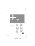
 EDP‐CM‐LPC1113 CPU Module User Manual Version 1.00 © Electrocomponents plc
Page 1
Contents 1. Introduction
2. 2.1 2.2 2.3 2.4 2.5 Pin Allocation
4 Allocation of MCU pins to backplane functions .............................. 4 Resources Used/Available by LPC1113 ........................................ 6 Alphabetical Listing of MCU Pins................................................... 7 Backplane - Base Board Signals ................................................... 8 Mapping Aid................................................................................. 11 3. Solder Link Options
12 4. Zero Ohm Links
16 5. 5.1 5.2 5.3 Software Support
17 RSEDP_Test_Suite ..................................................................... 17 MC1_Test_Suite.......................................................................... 17 MC2_Test_Suite.......................................................................... 18 © Electrocomponents plc
3 Page 2
1.
Introduction
The RS‐EDP platform is a system, has been designed to utilise many different manufacturers’ microprocessors. To support NXP range or ARM/Cortex MCU’s a single Command Module (CM) has been designed to accommodate four different device types. These are LPC2368 (ARM7), LPC1768 (Cortex M3), LPC1343 (Cortex M3) and LPC1113 (Cortex M0). Each of the boards comes with its own suite of software to fully exercise the RS‐EDP Application Modules and the peripherals available on the MCU device. In an RS‐EDP system there is usually one Command Module / CPU Module (CM) and one or more Applications Modules (AM) plugged in to the Base Board (BB). These NXP modules have been designed as the Command Module for the system. The ‘Command Module’ in a system dictates whether the whole system is a 3.3V one or a 5.0V one. All of these modules use a 3.3V microprocessor and consequently the I/O is mostly 3.3V also. To tell the rest of the system the Command Module is a 3.3V one not a 5.0V one, the Vcc_CM line on the base board is connected to 3.3V by the tracking on the Command Module board. This Vcc_CM is used as a reference by the other modules, such as the analogue module, to limit the output voltage to 3.3V. The command voltage line is also used by the #RESET circuit, as the voltage reference to pull up to after the reset line has been asserted low. The CPU Module maps the I/O of the NXP MCU on the board to the backplane of the RS‐EDP system. As there are quite a few dual function pins on the NXP processors and hence several link options have been made to accommodate the various options the user may wish to use. Extensive use of the I2C capability is used to communicate to the application modules in the system. © Electrocomponents plc
Page 3
2.
Pin Allocation
2.1 Allocation of MCU pins to backplane functions
The CM has been mapped to the backplane to maximise the functionality of the system and the AMs. A document called a Pin Allocation Spreadsheet exists which details the mapping of the pins to the backplane. The details of this mapping are detailed below. Below are detailed the pin number of the MCU, the pin name, a comment on its usage and the signals name to which it is allocated on the backplane. As the same PCB is used for variants of LPC processor some of the mapping may appear a little strange. For example this device has no CAN but is allocated some CAN resource on the backplane. This is because other NXP variants do have a CAN controller on board and the mapping is done to accommodate this other device. Pin 34 & 28 32 33 & 39 35 29 40 3 42 6 7 15 16 1 4 8 20 19 5 30 36 37 38 43 48 41 44 45 10 27 LPC1113FBD48 Name of function used on PIC TDO/PIO1_1/AD2/CT32B1_MAT0 & PIO0_9/MOSI0/CT16B0_MAT1 TDI/PIO0_11/ADC0/CT32B0_MAT3 TMS/PIO1_0/AD1/CT32B1_CAP0 & SWDIO/PIO1_3/AD4/CT32B1_MAT2 TRST/PIO1_2/AD3/CT32B1_MAT1 SWCLK/PIO0_10/SCK0/CT16B0_MAT2 PIO1_4/AD5/CT32B1_MAT3/WAKEUP #RESET/PIO0_0 PIO1_11/AD7 XTALIN XTALOUT PIO0_4/SCL PIO0_5/SDA PIO2_6 PIO0_1/CLKOUT/CT32B0_MAT2 VDDIO PIO2_5 PIO2_4 VSSIO PIO1_10/AD6/CT16B1_MAT1 PIO3_0/#DTR PIO3_1/#DSR PIO2_3/#RI/MOSI1 PIO3_2/#DCD PIO3_3/#RI VSSIO VDDCORE PIO1_5/#RTS/CT32B0_CAP0 PIO0_2/SSEL0/CT16B0_CAP0 PIO0_8/MISO0/CT16B0_MAT0 © Electrocomponents plc
Comment RS‐EDP‐BASE BOARD ‐ mapping Name JTAG interface on LPC module JTAG interface on LPC module JTAG interface on LPC module JTAG interface on LPC module JTAG interface on LPC module 2 link options 2 link options 2 link options 2 link options Xtal on module Xtal on module 2 link options 2 Link options ‐ User LED1 Unusable as USB Unusable as USB 3 link options 3 link options 3 link options 2 link options 2 link options 2 link options 2 link options 2 link options 2 link options 2 link options 2 link options 2 link options 2 link options 2 link options 2 link options 2 link options AN0 AN8 #RESIN AN4 AN12 CNTRL_I2C_SCL CNTRL_I2C_SDA EVG1_GPIO42 EVG0_GPIO40 3.3V USB_DEV_D+ USB_DEV_D‐ SGND EVG5_GPIO50 EVG8_GPIO56 EVG0_GPIO40 MOTORP0H EVG9_GPIO57 MOTORH0_ENC0 EVG10_GPIO58 EMG_TRAP EVG11_GPIO59 MOTORP0L EVG12_GPIO60 MOTORH1_ENC1 EVG13_GPIO61 SGND 3.3V EVM5_GPIO47 MOTORP2H EVG17_GPIO65 MOTORP2L Page 4
2 31 13 26 25 24 23 22 12 21 9 18 11 17 14 47 46 PIO2_0/#DTR/SSEL1 PIO2_11/SCK0 PIO2_1/#DSR/SCK1 PIO2_2/#DCD/MISO1 PIO2_10 PIO2_9 PIO0_7/#CTS PIO0_6/SCK0 PIO2_8 PIO3_5 PIO1_8/CT16B1_CAP0 PIO3_4 PIO2_7 PIO1_9/CT16B1_MAT0 PIO0_3 PIO1_7/TXD/CT32B0_MAT1 PIO1_6/RXD/CT32B0_MAT0 © Electrocomponents plc
2 link options 2 link options 2 link options 2 link options 2 link options 2 link options 2 link options 2 link option 2 link option 2 link option 2 link option 2 link option 2 link option 2 link options 2 Link options 2 link options 2 Link options 2 Link options 2 Link options 2 Link options 2 Link options 2 Link options 2 Link options 2 Link options 2 Link options 3 link options 3 link options 3 link options 2 link option 2 Link options 3 Link options 3 link options 3 link options 3 Link options 3 link options 3 link options Page 5
EVG18_GPIO66 GPIO0 EVG6_GPIO52 GPIO1 EVG7_GPIO54 ASC1_TX_TTL_ASC0_DTR CAN1_RX EVG4_GPIO48 EVG19_GPIO67 CPU_DAC01_GPIO19 EVG3_GPIO46 CPU_DACO0_GPIO17 EVG2_GPIO44 EVM9_GPIO55 ASC1_RX_TTL EVM8_GPIO53 ASC1_TX_TTL EVM7_GPIO51 EVM6_GPIO49 GPIO2_MCIDAT0 EVM4_GPIO45 GPIO14_MCIPWR EVM3_GPIO43 GPIO12_MCICMD EVM2_GPIO41_CAPADC GPIO10_MCICLK GPIO9_I2S_RX_WS EVM1_GPIO23 CPU_DACO0_GPIO17 GPIO7_I2S_RX_CLK EVM0_GPIO21 ASC0_TX_TTL AN7 AN15 ASC0_RX_TTL AN6 AN14 2.2 Resources Used/Available by LPC1113
Resources Used/Available to LPC1113 3.3V SGND #RESIN AN0 AN4 AN6 AN7 AN8 AN12 AN14 AN15 ASC0_TX_TTL ASC0_RX_TTL ASC1_TX_TTL ASC1_RX_TTL ASC1_TX_TTL_ASC0_DTR CAN1_RX CNTRL_I2C_SCL CNTRL_I2C_SDA CPU_DACO0_GPIO17 CPU_DAC01_GPIO19 EVG0_GPIO40 EVG1_GPIO42 EVG2_GPIO44 EVG3_GPIO46 EVG4_GPIO48 EVG5_GPIO50 EVG6_GPIO52 EVG7_GPIO54 EVG8_GPIO56 EVG9_GPIO57 EVG10_GPIO58 EVG11_GPIO59 EVG12_GPIO60 EVG13_GPIO61 EVG17_GPIO65 EVG18_GPIO66 EVG19_GPIO67 EVM0_GPIO21 EVM1_GPIO23 EVM2_GPIO41_CAPADC EVM3_GPIO43 EVM4_GPIO45 EVM5_GPIO47 EVM6_GPIO49 EVM7_GPIO51 EVM8_GPIO53 EVM9_GPIO55 GPIO0 GPIO1 GPIO2_MCIDAT0 GPIO7_I2S_RX_CLK GPIO9_I2S_RX_WS GPIO10_MCICLK GPIO12_MCICMD GPIO14_MCIPWR © Electrocomponents plc
Page 6
MOTORP0H MOTORP0L MOTORH0_ENC0 MOTORH1_ENC1 MOTORP2H MOTORP2L EMG_TRAP USB_DEV_D+ USB_DEV_D‐ Local User LED1 2.3 Alphabetical Listing of MCU Pins
Pin 3 4 10 14 15 16 22 23 27 40 45 46 47 9 17 30 42 2 13 26 38 19 20 1 11 12 24 25 31 36 37 43 48 18 21 29 32 34 & 28 33 & 39 35 44 8 5 41 6 Alphabetic Listing of Available I/O #RESET/PIO0_0 PIO0_1/CLKOUT/CT32B0_MAT2 PIO0_2/SSEL0/CT16B0_CAP0 PIO0_3 PIO0_4/SCL PIO0_5/SDA PIO0_6/SCK0 PIO0_7/#CTS PIO0_8/MISO0/CT16B0_MAT0 PIO1_4/AD5/CT32B1_MAT3/WAKEUP PIO1_5/#RTS/CT32B0_CAP0 PIO1_6/RXD/CT32B0_MAT0 PIO1_7/TXD/CT32B0_MAT1 PIO1_8/CT16B1_CAP0 PIO1_9/CT16B1_MAT0 PIO1_10/AD6/CT16B1_MAT1 PIO1_11/AD7 PIO2_0/#DTR/SSEL1 PIO2_1/#DSR/SCK1 PIO2_2/#DCD/MISO1 PIO2_3/#RI/MOSI1 PIO2_4 PIO2_5 PIO2_6 PIO2_7 PIO2_8 PIO2_9 PIO2_10 PIO2_11/SCK0 PIO3_0/#DTR PIO3_1/#DSR PIO3_2/#DCD PIO3_3/#RI PIO3_4 PIO3_5 SWCLK/PIO0_10/SCK0/CT16B0_MAT2 TDI/PIO0_11/ADC0/CT32B0_MAT3 TDO/PIO1_1/AD2/CT32B1_MAT0 & PIO0_9/MOSI0/CT16B0_MAT1 TMS/PIO1_0/AD1/CT32B1_CAP0 & SWDIO/PIO1_3/AD4/CT32B1_MAT2 TRST/PIO1_2/AD3/CT32B1_MAT1 VDDCORE VDDIO VSSIO VSSIO XTALIN © Electrocomponents plc
Page 7
7 XTALOUT 2.4 Backplane - Base Board Signals
Base Board Signal Name #CS0 #CS1 #CS2 #CS3 #PSEN #RD #RESIN #RESOUT #WR #WRH 12V 12V 12V 12V 12V GND 12V GND 12V GND 12V GND 3.3V 3.3V 3.3V 3V BAT 5.0V 5.0V 5.0V A0_AD0 A1_AD1 A2_AD2 A3_AD3 A4_AD4 A5_AD5 A6_AD6 A7_AD7 A8_AD8 A9_AD9 A10_AD10 A11_AD11 A12_AD12 A13_AD13 A14_AD14 A15_AD15 ALE AN_REF AN0 AN1 AN2 AN3 AN4 AN5 AN6 AN7 AN8 AN9 AN10 © Electrocomponents plc
EDPCON1 133 134 135 136 137 138 139 140 127 128 124 129 130 1 3 4 5 6 7 8 9 10 11 12 13 EDPCON2 53 & 54 55 & 56 57 & 58 59 & 60 51 & 52 45 & 46 1 & 2 3 & 4 47 & 48 49 & 50 95 & 96 97 & 98 41 & 42 39 & 40 37 & 38 35 & 36 33 & 34 31 & 32 29 & 30 27 & 28 25 & 26 23 & 24 21 & 22 19 & 20 17 & 18 15 & 16 13 & 14 11 & 12 43 & 44 Break Out Connector P603 P603 P603 P603 P603 P603 P603 P603 P603 P603 P603 P603 P603 P603 P603 P603 P603 P601 P603 P603 P603 P603 P602 P602 P602 P602 P601 P601 P601 Page 8
26 27 47 47 47 47 48 48 48 48 44 44 44 42 45 45 45 6 2 6 1 5 2 4 1 3 2 4 1 AN11 AN12 AN13 AN14 AN15 ASC0_RX_TTL ASC0_TX_TTL ASC1_RX_TTL ASC1_RX_TTL_ASC0_DSR ASC1_TX_TTL ASC1_TX_TTL_ASC0_DTR CAN0_RX CAN0_TX CAN1_RX CAN1_TX CANH0 CANL0 CNTRL_I2C_SCL CNTRL_I2C_SDA CNTRL_SPI_#CS_NSS CNTRL_SPI_CLK CNTRL_SPI_MRST CNTRL_SPI_MTSR CPU_DACO0_GPIO17 CPU_DACO1_GPIO19 EMG_TRAP ETH_LNK_LED ETH_RX‐ ETH_RX_LED ETH_RX+ ETH_SPD_LED ETH_TX‐ ETH_TX+ EVG0_GPIO40 EVG1_GPIO42 EVG2_GPIO44 EVG3_GPIO46 EVG4_GPIO48 EVG5_GPIO50 EVG6_GPIO52 EVG7_GPIO54 EVG8_GPIO56 EVG9_GPIO57 EVG10_GPIO58 EVG11_GPIO59 EVG12_GPIO60 EVG13_GPIO61 EVG14_GPIO62 EVG15_GPIO63 EVG16_GPIO64 EVG17_GPIO65 EVG18_GPIO66 EVG19_GPIO67 EVG20_GPIO69_ASCO_RTS EVM0_GPIO21 EVM1_GPIO23 EVM2_GPIO41_CAPADC EVM3_GPIO43 EVM4_GPIO45 EVM5_GPIO47 EVM6_GPIO49 © Electrocomponents plc
14 15 16 17 18 89 91 93 99 95 97 121 123 38 40 114 111 109 113 107 115 105 103 61 63 65 67 69 71 73 75 77 78 79 80 81 82 83 84 85 86 87 88 92 42 44 62 64 66 68 70 61 & 62 63 &64 89 & 90 91 & 92 79 & 80 77 & 78 75 & 76 69 & 70 71 & 72 73 & 74 P601 P603 P602 P603 P602 P602 P602 P602 P602 P602 P602 P602 P602 P603 P603 P603 P603 P603 P603 P603 P603 P603 P601 P601 P602 P602 P602 P602 P602 P602 P602 P602 P602 P602 P602 P602 P602 P602 P602 P602 P601 P602 P601 P602 P601 P602 P601 P602 P601 P602 P601 P601 P601 P601 P601 P601 P601 P601 P601 Page 9
3 4 6 3 5 30 31 32 35 33 34 46 47 40 41 35 34 33 30 31 32 7 7 44 41 40 42 39 43 38 37 16 17 18 19 20 21 22 23 24 26 25 27 26 28 27 29 28 30 29 31 33 8 9 18 19 20 21 22 EVM7_GPIO51 EVM8_GPIO53 EVM9_GPIO55 EVM10_GPIO68_ASCO_CTS GPIO0 GPIO1 GPIO2_MCI_DAT0 GPIO3 GPIO4_MCI_DAT1 GPIO5_I2S_TX_WS GPIO6_MCI_DAT2 GPIO7_I2S_RX_CLK GPIO8_MCI_DAT3 GPIO9_I2S_RX_WS GPIO10_MCI_CLK GPIO11_I2S_RX_SDA GPIO12_MCI_CMD GPIO13_I2S_TX_CLK GPIO14_MCI_PWR GPIO15_I2S_TX_SDA GPIO24_AD7 GPIO25_AD15 GPIO26_AD6 GPIO27_AD14 GPIO28_AD5 GPIO29_AD13 GPIO30_AD4 GPIO31_ADI2 GPIO32_AD3 GPIO33_AD11 GPIO34_AD2 GPIO35_AD10 GPIO36_AD1 GPIO37_AD9 GPIO38_AD0 GPIO39_AD8 I2C_GEN0_SCL I2C_GEN0_SDA I2C_GEN1_SCL I2C_GEN1_SDA IRQ_GPIO16_CNTRL_I2C_INT IRQ_GPIO18_I2C_GEN0_INT IRQ_GPIO20_I2C_GEN1_INT IRQ_GPIO22_I2C_INT MOTOR_TCO_FB MOTORH0_ENC0 MOTORH1_ENC1 MOTORH2_ENC2 MOTORP0H MOTORP0L MOTORP1H MOTORP1L MOTORP2H MOTORP2L MOTORPWM SGND SGND SGND SGND SPI_SSC_#CS_NSS SPI_SSC_CLK © Electrocomponents plc
72 74 76 90 21 22 23 24 25 26 27 28 29 30 31 32 33 34 35 36 45 46 47 48 49 50 51 52 53 54 55 56 57 58 59 60 119 117 37 39 41 43 122 116 118 120 102 100 106 104 110 108 112 131 132 101 98 7 & 8 5 & 6 9 & 10 99 & 100 P601 P601 P601 P601 P603 P603 P603 P603 P603 P603 P603 P603 P603 P603 P603 P603 P603 P603 P603 P602 P601 P602 P601 P602 P601 P602 P601 P602 P601 P602 P601 P602 P601 P602 P601 P603 P603 P602 P602 P603 P603 P603 P602 P601 P601 P601 P601 P601 P601 P601 P601 P601 P601 P601 P603 P603 P603 P603 P602 P601 Page 10
23 24 25 32 13 15 14 16 17 19 18 20 22 21 23 24 25 12 8 8 10 9 11 10 12 11 13 12 14 13 15 14 16 15 17 29 28 45 44 11 10 9 7 48 45 46 47 38 37 40 39 42 41 43 46 46 46 46 36 36 SPI_SSC_MRST_MISO SPI_SSC_MTSR_MOSI USB_DEBUG_D‐ USB_DEBUG_D+ USB_DEV_D‐ USB_DEV_D+ USB_HOST_D‐ USB_HOST_D+ VAGND VAGND Vcc_CM Vcc_CM Vcc_CM 94 96 19 20 125 126 67 & 68 65 & 66 87 & 88 85 & 86 83 & 84 81 & 82 93 & 94 P601 P601 P603 P603 P603 P603 P601 P601 P603 P603 P603 34 35 39 38 37 36 5 5 43 43 43 Note: This spread sheet is derived from the Pin Allocation Spreadsheet for this CPU Module.
The user manual for the base board also contains details of the back plane signals and the pin outs.
2.5 Mapping Aid
AN0
AN8
1
3
2
AN4
AN12
1
3
2
ASC0_RX_TTL
AN6
AN14
1
4
3
2
ASC0_TX_TTL
AN7
AN15
1
4
3
2
1
3
2
MOTORP0L
EVG12_GPIO60
1
3
2
MOTORP2H
EVG17_GPIO65
1
3
MOTORP2L
EVG18_GPIO66
1
3
2
2
EMG_TRAP
EVG11_GPIO59
1
3
2
MOTORH0_ENC0
EVG10_GPIO58
1
3
2
MOTORH1_ENC1
EVG13_GPIO61
EVM6_GPIO49
GPIO2_MCIDAT0
1
3
2
2
EVM4_GPIO45
GPIO14_MCIPWR
1
3
EVM3_GPIO43
GPIO12_MCICMD
1
3
2
1
3
2
EVM2_GPIO41_CAPADC
GPIO10_MCICLK
PIO1_4/AD5/CT32B1_MAT3/WAKEUP
JP405
42
PIO1_11/AD7
46
PIO1_6/RXD/CT32B0_MAT0
JP440
JP439
47
PIO1_7/TXD/CT32B0_MAT1
36
PIO3_0/#DTR
43
PIO3_2/#DCD
JP409
MOTORP0H
EVG9_GPIO57
1
3
JP403 40
2
JP412
JP417
10
PIO0_2/SSEL0/CT16B0_CAP0
JP418
27
PIO0_8/MISO0/CT16B0_MAT0
JP411
38
PIO2_3/#RI/MOSI1
JP410
37
PIO3_1/#DSR
JP413
48
PIO3_3/#RI
JP433
21
PIO3_5
JP434
9
PIO1_8/CT16B1_CAP0
18
PIO3_4
JP435
JP436
11
PIO2_7
USB_DEV_D+
USB_DEV_D‐
20
19
PIO2_5 (no USB functionality)
PIO2_4 (no USB functionality)
CNTRL_I2C_SCL
CNTRL_I2C_SDA
15
16
PIO0_4/SCL
PIO0_5/SDA
© Electrocomponents plc
Page 11
L
P
C
1
1
1
3 C
o
m
m
a
n
d M
o
d
u
l
e
3.3V
AN_REF
R101
SGND
VAGND
R102
#RESET
3.3V
4 PIO0_1/CLKOUT/CT32B0_MAT2
1
VCC_CM
1 EVG0_GPIO40
3
User LED D401
JP406
2
PIO2_6
EVG1_GPIO42
JP430
2
3
1
JP429
2
3
1
1
3
CPU_DACO0_GPIO17
EVG2_GPIO44
24
PIO2_9
25
PIO2_10
26
PIO2_2/#DCD/MISO1
JP428
2
30
PIO1_10/AD6/CT16B1_MAT1
JP407
2
2
PIO2_0/#DTR/SSEL1
JP421
2
1
3
GPIO0
EVG6_GPIO52
31
PIO2_11/SCK0
JP422
2
1
3
GPIO1
EVG7_GPIO54
14
PIO0_3
JP438
2
3
1
17
PIO1_9/CT16B1_MAT0
45
PIO1_5/#RTS/CT32B0_CAP0
23
PIO0_7/#CTS
JP437
2
CPU_DAC01_GPIO19
EVG3_GPIO46
EVG4_GPIO48
EVG19_GPIO67
1
3
4
EVG5_GPIO50
EVG8_GPIO56
EVG0_GPIO40
GPIO7_I2S_RX_CLK
EVM0_GPIO21
3
1
4
GPIO9_I2S_RX_WS
EVM1_GPIO23
CPU_DACO0_GPIO17
EVM5_GPIO47
EVM9_GPIO55
JP432
2
3
1
ASC1_TX_TTL
EVM7_GPIO51
ASC1_RX_TTL
EVM8_GPIO53
12
PIO2_8
22
PIO0_6/SCK0
JP431
2
3
1
13
PIO2_1/#DSR/SCK1
JP426
2
1
3
ASC1_TX_TTL_ASC0_DTR
CAN1_RX
3.
Solder Link Options
Many of the options for the Command Module board require a solder bridge to be made or a track to be cut. The CM board has been designed to be configured in the most popular setting by using a small track between the options, which will require cutting with a sharp knife before making the alternate connection options. A documents called a Mapping Aid exist to help explain the resources available on the MCU and how it can interface with the other modules within the system. An extract from it is in the section above. The options are as follows: VDDA JP201 (1‐2) VDDA on the MCU is connected to 3.3V JP201 (2‐3) VDDA on the MCU is connected to AN_REF on the backplane The LPC1113 does not use this VDDA reference so the jumper setting is irrelevant. This function is provided for the LPC1768 and LPC2368 variants of this CM. VDDA is the power supply voltage to the on board ADC circuitry. Using a lower noise AN_REF signal will yield better results. The AN_REF signal is usually provided by a stable voltage reference source present on the Analogue Module. Vref JP202 (1‐2) VREF on the MCU is connected to 3.3V JP202 (2‐3) VREF on the MCU is connected to AN_REF on the backplane The LPC1113 does not use this Vref signal. This function is provided for the LPC1768 and LPC2368 variants of this CM. This is the voltage reference that is used to measure the analogue input voltages against. An AN_REF signal will provide better results than the 3.3V signal. The AN_REF signal is usually provided by a stable voltage reference source present on the Analogue Module. VBAT JP203 (1‐2) VBAT on the MCU is connected to 3.3V JP203 (2‐3) VREF on the MCU is connected to 3V3_BATT on the backplane This option is irrelevant as the LPC1113 does not a VBAT terminal. This jumper is provided for the LPC1768/LPC2368 variants of the Command Module. Port PI00 Options PIO0_1/CLKOUT/CT32B0_MAT2 EVG0_GPIO40 JP406 (2‐1) JP406 (2‐3) (Default) User LED1 Selecting JP406 position 2‐3 allows use of the on board user led LED1 (D401). Note: EVG0_GPIO40 is also available on JP407. (PIO1_10) PIO0_2/SSEL0/CT16B0_CAP0 JP417 (2‐1) MOTORP2H JP417 (2‐3) (Default) EVG17_GPIO65 © Electrocomponents plc
Page 12
PIO0_3 GPIO7_I2S_RX_CLK JP438 (2‐3) JP438 (2‐1) (Default) EVM0_GPIO21 PIO0_6/SCK0 ASC1_RX_TTL JP431 (2‐3) JP431 (2‐1) (Default) EVM8_GPIO53 PIO0_8/MISO0/CT16B0_MAT0 JP418 (2‐1) MOTORP2L JP418 (2‐3) (Default) EVG18_GPIO66 Port PIO1 Options PIO1_4/AD5/CT32B1_MAT3/WAKEUP JP403 (2‐1) (Default) AN0 JP403 (2‐3) AN8 PIO1_6/RXD/CT32B0_MAT0 ASC0_RX_TTL JP440 (2‐1) (Default) JP440 (2‐4) AN6 JP440 (2‐3) AN14 Position 2‐1 is the main RS232/UART channel. Incoming logic level receive traffic is routed from the Communication Module. PIO1_7/TXD/CT32B0_MAT1 JP439 (2‐1) (Default) ASC0_TX_TTL JP439 (2‐4) AN7 JP439 (2‐3) AN15 Position 2‐1 is the main RS232/UART channel. Outgoing logic level transmit traffic is routed to the Communication Module where it is translated into RS232/RS485 logic levels. PIO1_8/CT16B1_CAP0 JP434 (2‐3) GPIO14_MCI_PWR JP434 (2‐1) (Default) EVM4_GPIO45 PIO1_9/CT16B1_MAT0 JP437 (2‐3) GPIO9_I2S_RX_WS JP437 (2‐1) (Default) EVM1_GPIO23 JP437 (2‐4) CPU_DACO0_GPIO17 Note: CPU_DACO0_GPIO17 is also available on JP430 (PIO2_9) PIO1_10/AD6/CT16B1_MAT1 JP407 (2‐1) (Default) EVG5_GPIO50 JP407 (2‐3) EVG8_GPIO56 JP407 (2‐4) EVG0_GPIO40 Note: EVG0_GPIO40 is also available on JP406. (PIO0_1) © Electrocomponents plc
Page 13
PIO1_11/AD7 JP405 (2‐1) (Default) JP405 (2‐3) AN4 AN12 Port PIO2 Options PIO2_0/#DTR/SSEL1 JP421 (2‐1) (Default) GPIO0 JP421 (2‐3) EVG6_GPIO52 PIO2_1/#DSR/SCK1 JP426 (2‐1) (Default) ASC1_TX_TTL_ASC0_DTR JP426 (2‐3) CAN1_RX PIO2_2/#DCD/SISO1 JP428 (2‐1) (Default) EVG4_GPIO48 JP428 (2‐3) EVG19_GPIO67 PIO2_3/#RI/MOSI1 JP411 (2‐1) EMG_TRAP JP411 (2‐3) (Default) EVG11_GPIO59 PIO2_7 JP436 (2‐3) GPIO10_MCI_CLK JP436 (2‐1) (Default) EVM2_GPIO41_CAPADC PIO2_8 JP432 (2‐3) ASC1_TX_TTL JP432 (2‐1) (Default) EVM7_GPIO51 PIO2_9 JP430 (2‐3) CPU_DACO0_GPIO17 JP430 (2‐1) (Default) EVG2_GPIO44 Note: CPU_DACO0_GPIO17 is also available on JP437 (PIO1_9) PIO2_10 JP429 (2‐3) CPU_DAC01_GPIO19 JP429 (2‐1) (Default) EVG3_GPIO46 PIO2_11/SCK0 JP422 (2‐1) (Default) GPIO1 JP422 (2‐3) EVG7_GPIO54 © Electrocomponents plc
Page 14
Port PIO3 Options PIO3_0/#DTR JP409 (2‐1) JP409 (2‐3) (Default) PIO3_1/#DSR JP410 (2‐1) JP410 (2‐3) (Default) PIO3_2/#DCD JP412 (2‐1) JP412 (2‐3) (Default) PIO3_3/#RI JP413 (2‐1) JP413 (2‐3) (Default) PIO3_4 JP435 (2‐3) JP435 (2‐1) (Default) PIO3_5 JP433 (2‐3) JP433 (2‐1) (Default) MOTORP0H EVG9_GPIO57 MOTORH0_ENC0 EVG10_GPIO58 MOTORP0L EVG12_GPIO60 MOTORH1_ENC1 EVG13_GPIO61 GPIO12_MCI_CMD EVM3_GPIO43 GPIO2_MCI_DAT0 EVM6_GPIO49 Not Connected Options As the circuit board for the LPC1113 is also used for higher pin count MCU such as LPC2368 and LPC1768, there are some configurations options that are not used. These are shown on the circuit schematic but do not have any relevance for this LPC1113 module as the pins are not connected. These jumper options are detailed below. JP401 (2‐1) (Default) AN2 JP401 (2‐3) AN10 JP402 (2‐1) (Default) AN1 JP402 (2‐3) AN9 JP404 (2‐1) (Default) AN5 JP404 (2‐3) AN13 AN3 JP408 (2‐1) (Default) JP408 (2‐4) AN11 JP408 (2‐3) CPU_DACO0_GPIO17 JP414 (2‐1) MOTORH2_ENC2 © Electrocomponents plc
Page 15
JP414 (2‐3) (Default) EVG14_GPIO62 JP415 (2‐1) JP415 (2‐3) (Default) MOTORP1H EVG15_GPIO63 JP416 (2‐1) JP416 (2‐3) (Default) MOTORP1L EVG16_GPIO64 JP419 (2‐1) JP419 (2‐4) (Default) JP419 (2‐3) CAN0_TX CAN0_TX_LOCAL I2C_GEN0_SDA JP420 (2‐1) JP420 (2‐4) (Default) JP420 (2‐3) CAN0_RX CAN0_RX_LOCAL I2C_GEN0_SCL JP423 (2‐1) (Default) JP423 (2‐3) IRQ_GPIO16_CNTRL_I2C_INT
IRQ_GPIO18_I2C_GEN0_INT JP424 (2‐1) (Default) JP424 (2‐3) ASC1_RX_TTL EVM10_GPIO68_ASCO_CTS JP425 (2‐1) (Default) JP425 (2‐3) ASC1_TX_TTL CAN1_TX JP427 (2‐1) JP427 (2‐3) (Default) MOTOR_TCO_FB User LED0 4.
Zero Ohm Links
CAN Load Resistor JP501 This link when inserted includes a 120 ohm resistor across CANH0 and CANL0. The default is connected. This option is irrelevant as the LPC1113 does not a CAN peripheral. This jumper is provided for the LPC1768/LPC2368 variants of the Command Module, which have a CAN transceiver fitted. AN_REF R101 This zero ohm link when inserted provides a 3.3V reference for the EDP platform. The 3.3V used is the local supply voltage derived from a local voltage regulator. This link should be used in the absence of a 3.3V voltage reference voltage provided by the Analogue Module when fitted. The default position is not connected. AGND & VAGND R102 This link when inserted provides a way of connecting the VAGND to the SGND. This is the default position. The two grounds alternatively can be connected to each other on the analogue module or on the base board. © Electrocomponents plc
Page 16
5.
Software Support
The NXP Command Module for the RS‐EDP platform is supported by all of the necessary software drivers to make driving of the platform very easy. All the low level support for the devices controlled by I2C for example have been written, as well as a test menu to exercise each of the modules independently of the others. This therefore provides working example of the code which will allow students and users to cut and paste various sections into their own applications. Each Applications Module has its own collection of header files, which provides the support for the functions that control it. Each module has its own set of high level functions that can be called to operate and control the hardware. This makes life a lot easier for the user, who can then spend most of his time working at the higher level application layer. The software has been packed up as several ZIP file which can be downloaded and unpacked. Most of the projects have been written for the Keil uVision environment. The majority of the applications written use the serial comm. channel ASC0 for outputting data to a terminal emulator. With this in mind a serial terminal emulation program should be used to read traffic outputted from the RS‐EDP platform. Hyper Terminal is included in windows as part of the Windows Operating system but this does not work reliability. With this in mind it may be worth looking at other terminal emulator especially if they are to be used with USB‐RS232 converters. The terminal emulator should be set up for 115,200 baud 8 data bits no stop bit no parity No flow control The default jumper options for JP439 and JP430 should be left in place to ensure serial traffic is routed to the communication module. Always check the software to see if the baud rate has been changed. Some of the provided software may includes... 5.1 RSEDP_Test_Suite
This software exercises the NXP LPC1113 MCU peripherals including the on board ADC, PWM output, input capture, I2C, and I/O. The software also allows you to exercise the basic Application Modules, which are the Communication Module, the Digital I/O Module, and the Analogue Module. A suite of drivers and test menus are provided to fully exercise all the hardware on these boards. 5.2 MC1_Test_Suite
This is similar to the RSEDP_Test_Suite, but the test menus provided are for the MC1 Brushed DC Motor Drive Application Module. The motors are nominally 12V brushed DC motors running in a full H bridge configuration. The test suite allows you to accelerate the motor, change its direction, turn the brake on and off, as well as allowing the monitoring of motor current, DC link voltage and tacho feedback signals. The MC1 motor drive module also has many external inputs for limit switch detection and conditioning of motor related stimuli. The provided software library will therefore allow you to fully exercise your motor. © Electrocomponents plc
Page 17
5.3 MC2_Test_Suite
This is similar to the MC1 test suite but for brushless DC/AC motors. The software assumes you have an MC2 motor drive module fitted, and you want to communicate to it via I2C packets. This set of software therefore allows you communicate with the MC2 motor drive module across the I2C backplane network, present in the RSEDP system. You can have up to three MC2 motor drives fitted and this suite of software allows you to communicate with all of them. © Electrocomponents plc
Page 18