1
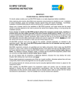
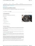
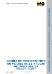
Department of Mechatronic Systems Engineering Simon Fraser University 250-13450 102 Avenue Surrey, BC V3T 0A3 #250 13450 – 102nd Avenue Surrey, British Columbia, V3T 0A3 Maureen Hindy Faculty of Applied Science – School of Mechatronic Systems Engineering Simon Fraser University Surrey Central City Galleria 4 2 July, 2013 Dear Ms Hindy, Please accept the accompanying document entitled ‘SF-1 Mechanical Division: Technical Manual’. This submission is to fulfill the appropriate course requirement for MSE 411. The technical manual will give an in depth understanding to SFU’s Formula SAE team in using, tuning, and maintaining the SF-1 car. The intended audience is the end user of the SF-1 car. As such, the manual is mainly concerned with maintenance, tuning, and customization. However, we also added operational guidelines where appropriate; these items may be confused with content similar to what would be found in a user manual, but were included when the end user would find them applicable or helpful. Sincerely, SF-1 Mechanical Division Spencer Steele George Ioannou Batuhan Atalay Richard Douglas Ph: 604 785 7060 [email protected] www.SF1engineering.com SF-1 Engineering @SF1engineering SF-1 Mechanical Technical Manual 2 July, 2013 Spencer Steele George Ioannou Batuhan Atalay Richard Douglas 301088654 301092041 301099145 301093301 TABLE OF CONTENTS 1.0 How to Use This Manual 1 2.0 General 2.1 Identification, Engine & Serial Numbers 2.3 Modifications 2.4 Instruments & Controls 2.5 Body 2.6 Electrical System 2 2 3 3 4 4 3.0 Powertrain Specifications & Maintenance 3.1 Engine & Transmission 3.2 Gear Ratios 6 6 7 4.0 Performance, Safety, and Other Testing 4.1 Performance Testing 4.2 Safety Testing 4.3 Road Test 8 8 9 10 5.0 Suspension Tuning 5.1 Suspension Overview & Layout 5.2 Suspension Tuning & Alignment 5.2.1 Ride Height 5.2.2 Spring Rate 5.2.3 Camber angle 5.2.4 Caster angle 5.2.5 Toe 5.2.6 Final Safety Check 5.3 Alignment & Suspension Specifications 11 11 12 13 13 14 15 16 16 17 6.0 Lubrication & Other Maintenance 6.1 Routine Maintenance 6.2 Running-In Speeds 6.3 General Data 6.4 Tire Type and Pressure Wet Conditions: Dry Conditions: 6.5 Running-In Period 18 18 19 19 21 21 21 22 7.0 23 References i LIST OF FIGURES Figure 1: Shorai Lithium Ion Battery 4 Figure 2: Shorai Charger 4 Figure 3: Main Starter Relay & Fuse Block 5 Figure 4: Yamaha 600cc Liquid Cooled 4 Cylinder 6 Figure 5: Driven sprocket with rear brake caliper 7 Figure 6: Yamaha YZF 600 Engine 18 LIST OF TABLES Table 1: Suspension Components Materials Table 12 Table 3: Suspension Alignment Specifications 17 ii 1.0 HOW TO USE THIS MANUAL This technical manual is designed for automotive enthusiasts, tuners, and drivers of the SF-1 race car. It covers various subjects from features of the car which are applicable to the user, to instructions to the tuner. Occasionally, design considerations and features of the car which were deliberately included by the SF-1 Engineering team, which may go unnoticed to an untrained observer, are included. As this is a manual for a race car, not a mass-produced passenger car, a certain level of mechanical aptitude and automotive knowledge is assumed on behalf of the reader. It should be referenced when racing, tuning, or modifying the SF-1 car. The SF-1 Engineering team recommends that the driver and pit crew become acquainted with the information contained in this report before starting a race weekend or event. Throughout the manual, look for the “Christmas Tree” icon and accompanying text box for items which we feel will be beneficial to the reader. The notes are shown with the Green, Yellow, or Red lights on as follows: The Christmas Tree with the Green Light lit up shows a “helpful hint” which may help the tuning process go a little quicker and easier. The Christmas Tree with the Yellow Light lit up shows a caution item which deserves your careful attention. The Christmas Tree with the Red Light and Exclamation Point shows a warning item which could create a hazardous condition if not respected. 1 2.0 GENERAL 2.1 Identification, Engine & Serial Numbers The identification number can be found stamped onto the chassis tube located close the drivers left shoulder. Explanation of Identification Number i.e., The current chassis number: SF-1-14 SF Simon Fraser 1 Iteration of cars produced at Simon Fraser 14 Year of competition Engine Number: The engine number is stamped on the right side of the transmission casing and can be used to assist part identification. 2.2 Dimensions & Weights Exterior Dimensions Wheelbase 81” Front track 55” Rear Track 53” Interior Dimensions The car was designed to accommodate drivers up to 6’8” and up to a maximum of 225 lbs. The seat is custom molded to the driver of the car and reproduced in carbon fibre for the ultimate in comfort, support and weight savings. The pedals are adjustable to accommodate different body types. Weights Dry Weight 492 lbs Wet Weight 522 lbs 2 2.3 Modifications Modifications should be limited to consumables, i.e., brake pads, rotors, oil, fuel, fluids, etc. As all the structural members of the race car have gone through FEA analysis, any modifications to the structure should be performed by professionals and backed by extensive study and analysis. It is advisable to get in contact with SF-1 for modification concerns. 2.4 Instruments & Controls The main controls of the vehicle are located in the instrument cluster in front of the driver: There are safety features as well as driving features. Brake Light: The race car is equipped with an automatic center-mounted brake light that switches on whenever the car is on and the brakes are applied. Brake-over-travel-switch: an automatic switch which kills the engine and fuel pump in case of the brake pedal over-travelling. Master Switches: The vehicle is equipped with two master switches which perform the shutdown procedure. Primary Master Switch: located on the driver’s right side of the vehicle near the Main Hoop. It disables all power to all electrical circuits, including the battery, alternator, lights, fuel pumps, ignition and electrical controls. Cockpit Mounted Master Switch: ON/OFF switch which enables/disables power to the ignition and the fuel pump. Transponder: The race car is equipped with a power transponder for measuring lap times, located on the driver’s rights side, forward of the front roll hoop. Digital Display: Located on the digital display unit, this turns the digital display unit on and off. Data Logging: enables data logging from the digital display unit, it can be set while the digital display unit is active. 3 2.5 Body SF-1 Bodies can come in two configurations: The standard configuration is aircraft grade polished aluminum skinning; while the performance option includes vacuum molded carbon fiber. 2.6 Electrical System The electrical system is powered by a 12 volt lithium ion battery made by Shorai. Figure 1: Shorai Lithium Ion Battery While the vehicle is running, the battery is charged by the alternator, driven by the engine. When not in use, the battery should be left on charge using the supplied Shorai battery charger: Figure 2: Shorai Charger 4 All of the components of the car are protected using a fuse block mounted off the side of the battery. If troubleshooting electrical problems, be sure to check this first. Figure 3: Main Starter Relay & Fuse Block 5 3.0 3.1 POWERTRAIN SPECIFICATIONS & MAINTENANCE Engine & Transmission The engine was originally purposed for a 1994-95 Yamaha 600 YZF. It features four cylinders that are water cooled and fed by 4 separately synchronized carburetors. The transmission is encased with the engine and is described as a 6 speed sequential. Type 4 Cylinder 4 Stroke Liquid cooled DOHC, 4 valves per cylinder Bore and Stroke 62 x 49.6 mm Compression Ratio 12.0:1 Induction 4x 36mm Keihin CV Downdraft Carburetors Ignition/Starting: Capacitive Discharge Ignition (CDI) Power 100 bhp (72.9 kW) @ 11500 rpm Torque 65.7 Nm @ 9500 rpm Transmission/Drive 6 Speed Sequential/Chain Average Fuel Consumption 16.4 km/litre Figure 4: Yamaha 600cc Liquid Cooled 4 Cylinder 6 3.2 Gear Ratios The 6 speed transmission in the 1995 Yamaha YZF600R engine features the following gear ratios: 1st gear 2nd gear 3rd gear 4th gear 5th gear 6th gear 37/13= 2.85:1 37/19= 1.95:1 34/22 = 1.55:1 28/21 = 1.33:1 25/21 = 1.19:1 29/27 = 1.07:1 At the output shaft of the transmission there is a 3.5:1 gear ratio with the driven axle which gives it a good balance of takeoff acceleration as well as a top speed (~190km/h). The driver sprocket has 15 teeth and the driven sprocket has 52. They are connected by a Forward Powersports #530 O-ring motorcycle chain. The benefit of using an O-ring chain is that the chain links do not need external lubrication due to its design. Additionally, the rubber O-ring built between the outside link plate and the inner roller links prevents dirt and other contaminants from entering the inside of the chain linkages, smooth operation and power transmission is guaranteed. A unique feature about the SF-1 car is that the driven sprocket is also used as the rear brake rotor (Refer to figure for details). The benefit of this design is that it reduces the weight on the rear of the car by reducing the usual ‘1 brake per wheel’ design to a single brake that acts for the entire rear axle. Figure 5: Driven sprocket with rear brake caliper 7 4.0 4.1 PERFORMANCE, SAFETY, AND OTHER TESTING Performance Testing Theoretical track performance figures are as follows: Acceleration (0-60mph) 4.3 s Top Speed 190 km/h Maximum force during braking 2.0 g It should be noted that these values may not be attained easily as the car is designed for maximum performance on an autocross track. It is intended to handle very well during cornering while placing minimum strain and loading on the driver. Performance testing was done on the car in accordance to the rulebook as well. In the table below you will find a brief summary on the performance testing the team conducts on the car: Acceleration Testing to measure the acceleration of the vehicle (0-60mph). Multiple runs were performed and the average time was taken. Skid-pad Measures the cornering ability of the car on a flat surface while making a constant radius turn. The car was driven in a circular manner in between set cones to determine the maximum speed and G-forces attained Autocross This tests all aspects of the vehicle: Braking, accelerating, constant turns, hairpin turns etc. Endurance and Similar to an autocross event but over a longer track (~22km vs. the Efficiency ~1km for autocross) that tests engine performance, fuel consumption, comfort and drivability of the car over extended lengths of time. Details of the testing including timed results, track mock-ups and videos can be found on the team website, www.SF1engineering.com. 8 A special note should be made that the fuel injection system that the vehicle has installed was also designed by university students that conducted research on current industry technologies and applied any necessary changes that improved fuel delivery to the engine. 4.2 Safety Testing The SF-1 Formula car has been rigorously tested to ensure user safety. Using our 3D modeling software (SolidWorks) we performed analytical testing on all the components of the vehicle. Every aspect of the car was tested to ensure it would not fail and that if any issues were to arise, that they did not endanger the driver in any way. Due to the team competing in professional events, there are certain criteria that need to be fulfilled in order for the team to be able to compete. The organizers provide a list of loading conditions that are to be implemented and tested on the model. The list includes loading on the main roll hoop, front bulkhead, secondary roll hoop, torque testing on the drive sprocket and brakes, suspension arms and many more. Documentation of all the testing is provided to the event organizers and if they feel that the car does not fulfill the criteria then it is not allowed to race. The list of loading conditions in addition to any other requirements for the competition can be found online at http://students.sae.org/competitions/formulaseries/rules. In addition, and although not required by the competition, testing was also conducted on the 6point harness that is installed on the car. Using Madymo (a worldwide standard software for analysing and optimizing occupant safety designs) the car seat was recreated and testing was performed to ensure that the driver’s body did not undergo any unnecessary loading. Furthermore, it lead to the design of the head cushion placed at the top of the seat that improves driver comfort and minimizes whiplash. 9 4.3 Road Test Everyone who likes driving on a race track, but is limited due to the associated costs, will be happy to know that the SF-1 Formula car allows you to do just that with your own formula car at drastically reduced costs. All you need to do is provide transportation to take the car to the track and all that is left is driving it. This car is built to withstand regular track conditions that enable you to take it out for a weekend of fun. The tires can be interchanged between slicks and wet slicks, depending on the weather conditions. Please be advised that this vehicle is NOT for use on commercial roads. Driving this vehicle on a commercial road can lead to a large fine and possible prosecution. 10 5.0 5.1 SUSPENSION TUNING Suspension Overview & Layout The SF-1 car uses Formula 1- inspired, race-proven technology to ensure excellent handling under normal track conditions. The suspension layout, including both purchased and customdesigned parts, has been engineered as a holistic system with fast response, high strength, and maximum stability in mind. The suspension system has also been painstakingly thought out for easy modification and chassis tuning between race events. The car rests on a four-wheel independent suspension; in particular, the double-wishbone geometry which has been the staple of high-profile Formula 1 teams for decades. In addition, the geometry has been designed for maximum stability under the high lateral and longitudinal loading (hard cornering and braking), while providing adequate driver input. The shock/spring coilovers are actuated via a custom-built pushrod and bell crank linkage, which alleviates all theoretical moments from the wishbones. This allows the coilovers to be mounted inboard of the suspension and the control arms to be built out of lighter material, both of which reduce the suspension’s unsprung mass. Spherical bearings and rod ends are all made from alloy steel, and use greasable bronze bushings necessary for high-loading applications and long service life. For quick reference on the materials used for major suspension components, refer to the table below: 11 Front Suspension Component Control Arm - Upper Control Arm - Lower Bell Crank Push Rod Upright Spherical Bearings - body - bushing Rod Ends - body - bushing Material SAE1020 SAE1020 6061 Billet SAE1020 6061 Billet Alloy Steel Phosphor Bronze Alloy Steel Phosphor Bronze Rear Suspension Component Control Arm - Upper Control Arm - Lower Bell Crank Push Rod Upright Spherical Bearings - body - bushing Rod Ends - body - bushing Material SAE1020 SAE1020 6061 Billet SAE1020 6061 Billet Alloy Steel Phosphor Bronze Alloy Steel Phosphor Bronze Table 1: Suspension Components Materials Table 5.2 Suspension Tuning & Alignment The following section outlines the procedure for setting suspension alignment (“chassis tuning”) in the SF-1 car. The alignment must be set in the following order: 1. 2. 3. 4. 5. Ride height and spring rate Rear caster and camber Front caster and camber Front toe Final alignment & safety check Before chassis tuning, ensure the entire weight of the car is supported by the wheels. Turn the steering wheel to the “straight ahead” position and have an assistant hold it securely, or otherwise clamp the steering wheel in that position. The alignment should be set with the car as close as possible to its race day setup: with a full tank of fuel and a driver (or suitably heavy ballast) in the driver’s seat, and tires at operating pressure. 12 Only approved alignment equipment, and an operator trained in its use, should be used to align any car. 5.2.1 Ride Height 1. Measure the ride height with a driver (or suitable ballast) in the driver’s seat, and all fluids in the car that would normally be used during a race event (fuel, oil, coolant, etc.). 2. Measure the distance from the ground to the bottom of the lowest frame rail on the applicable corner of the car. 3. To adjust height, loosen the ride height adjustment cam nut. 4. Turn the ride height adjustment cam bolt to raise or lower the suspension. Have an assistant check ride height at the applicable corner while adjusting. 5. Tighten the ride height adjustment cam nut. 6. Re-check that ride height is within spec. 5.2.2 Spring Rate The spring rate must be checked with the car resting on the ground (not on jack stands, service jack, or other hoisting apparatus). Check that tire pressure is the same as it would be on a track day. 1. Measure ride height from the ground to a frame rail, at the applicable corner of the chassis. 2. Apply a suitable ballast to the applicable corner of the chassis. Use the specifications table at the end of this section for reference. 3. Re-measure the ride height to get an appropriate spring displacement. 13 5.2.3 Camber angle Camber angle should be set to the specification range in the table at the end of this section. The camber angle may be changed in one of two ways: by lengthening the control arms or shimming out the mounts. The recommended procedure is to set the control arm lengths to get as close as possible to specification, and shim the mounts for fine adjustments or chassis tuning between track events. Note: Adjusting the caster angle will slightly change the camber angle, and vice-versa. The two must be set simultaneously, with toe set after these two. To set control arm length: To increase positive camber, lengthen both ends of the upper control arms (turn rod ends counter-clockwise) or shorten both lower control arms (turn rod ends clockwise). To increase negative camber, reverse these directions. 1. Use an open end wrench to loosen rod end jam nut. 2. Remove thru bolt from appropriate control arm mount. 3. Turn rod end according to guidelines above. Note: The rod end must be re-installed with the thru bolt orientated horizontally to reattach to the mount. Thus, the rod end can only be adjusted by multiples of 1/2 -turn, which corresponds to a change in length of ± 1/40 inch. 4. Align rod end with mount holes and re-install thru bolt. Use washers to shim up either side of the rod end spacer to prevent binding. Install washers and a new Ny-Loc nut. 5. Re-check caster and camber angles; repeat steps 2-4 as necessary. 6. Securely torque thru bolt with the new Ny-Loc nut. Tighten rod end jam nut. To shim control arm mount: 1. Loosen the two bolts connecting mount to frame rail. 2. Remove or install shims between the angled shim and the framerail, according to the guidelines above. Ensure the slot in the shim faces downwards. 1. Note: The angled shim must not be removed. 3. Snug up the two bolts connecting mount to frame rail. 4. Re-check camber and caster angles; repeat steps 2-3 as necessary. 5. Securely torque the mounting bolts using new Ny-Loc nuts and washers. 14 5.2.4 Caster angle Caster angle should be set to the specification range in the table at the end of this section. The caster angle may be changed in one of two ways: by lengthening the control arms or shimming out the mounts. The recommended procedure is to set the control arm lengths to get as close as possible to specification, and use mount shims for fine adjustments or chassis tuning between track events. To set control arm length: To increase positive caster, lengthen the front rod ends of the upper control arm while shortening the rear rod end of the lower control arm, or shorten the rear rod ends of the upper control arm while lengthening the front rod end of the lower control arm. To increase negative caster, reverse these directions. 1. Use an open end wrench to loosen rod end jam nut. 2. Remove thru bolt from appropriate control arm mount. 3. Turn rod end according to guidelines above. Note: The rod end must be re-installed with the thru bolt orientated horizontally to reattach to the mount. Thus, the rod end can only be adjusted by multiples of ½-turn, which corresponds to a change in length of ± 1/40 inch. 4. Align rod end with mount holes and re-install thru bolt. Use washers to shim up either side of the rod end spacer to prevent binding. Install washers and a new Ny-Loc nut. 5. Re-check caster and camber angles; repeat steps 2-4 as necessary. 6. Securely torque thru bolt with the new Ny-Loc nut. Tighten rod end jam nut. To shim control arm mount: 1. Loosen the two bolts connecting mount to frame rail. 2. Remove or install shims between the angled shim and the frame rail, according to the guidelines above. Ensure the slot in the shim faces downwards. Note: The angled shim must not be removed. 3. Snug up the two bolts connecting mount to frame rail. 4. Re-check camber and caster angles; repeat steps 2-3 as necessary. 5. Securely torque the mounting bolts using new Ny-Loc nuts and washers. 15 5.2.5 Toe Before adjusting toe, ensure the steering wheel is centered and secured in the “straight ahead” position. 1. 2. 3. 4. 5.2.6 Loosen the tie rod end clamps. Turn tie rod sleeves to lengthen/lengthen each tie rod as required. Re-check that toe is within specification as shown in the table below. Tighten tie rod end clamps. Final Safety Check After chassis adjustment is complete, a final safety check should be conducted. These steps may be completed in any order, but are necessary before starting a race event. Failure to complete a thorough safety check as outlined here may result in unsafe vehicle behaviour during performance-oriented driving. Check that all suspension hardware is torqued to specification. All safety-critical hardware uses either Ny-Loc nuts, or castle nuts with a cotter pin. Check that all Ny-Loc nuts are installed appropriately, with at least 2 bolt threads exposed out the open end of the nut. Check that a cotter pin is installed in all castle nuts. Grasp all control arms, push rods, and coil overs by hand and shake them vigorously to check for excessive play. Repair or replace any loose components as required. Record all suspension alignment settings before and after making changes to chassis tuning and keep track of the performance changes. 16 5.3 Alignment & Suspension Specifications Item Front Caster Front Camber Front Toe Alignment Specifications Min Spec Max Spec Notes +5.0 deg. +8.0 deg. L-R must be within 0.5 deg +1.5 deg. +2.5 deg. L-R must be within 0.5 deg 1/16" toed-in Rear Caster Rear Camber Rear Toe zero deg. +5.0 deg. zero inches +0.5 deg. +8.0 deg. Front Ride Height Rear Ride Height 2.0" 2.5" 3.0" 3.5" Item Spring Rate Test Spring Rate L-R must be within 0.5 deg Non-adjustable Chassis Tuning Specifications Spec Notes 100 lb Ballast weight 0.33" Approximate Jounce 500 lb/in Fox spec Table 2: Suspension Alignment Specifications 17 6.0 6.1 LUBRICATION & OTHER MAINTENANCE Routine Maintenance Various measures were taken by the SF-1 team to simplify the maintenance process as much as possible. Firstly, the chassis of the car can be disassembled into 2 separate pieces. The rear subframe (securing the engine, powertrain, etc.) is bolted onto the front half and can be disassembled in a matter of minutes. This allows the rear half of the frame, once all of the component bolts are removed, can be simply lifted off the ground. This provides easy access to the engine, transmission and power train components. Due to the light weight of the chassis, it was deemed that it would be much easier to simply lift the chassis of the engine as opposed to lifting the engine out from the chassis. With this method it is also easier for you to access the powertrain and the exhaust. Secondly, in the driver’s compartment, the layout is similar to an F-1 car. Equipped with a quick release steering wheel that allows removal within seconds, it provides access to the electronics bay. The side body panels and 6-point harness can easily be removed from the mounting brackets on the inside of the driver’s compartment as well. The front nose cone of the vehicle holds the impact attenuator and can be removed to provide access to the gas and brake pedals should any repairs or replacements need to be done. The engine has an abundance of maintenance information online from various Yamaha resources. It is integrated with a 6-speed transmission that is outlined in the gear ratio section. A picture of the model installed in the car can be seen in Figure 1. SF-1 is composed of core members that are firm believers of our product having a long life cycle. If you ever have an issue with the vehicle that you feel uncertain or unsafe repairing you will always be able to bring the car into the university to have it looked at Figure 6: Yamaha YZF 600 Engine 18 by the team, or have a member commute to your location to help with any maintenance. 6.2 Running-In Speeds During the first 5 kilometers of driving do not exceed 60 km/h. Avoid long periods of idling and do not over-rev the engine. Never overload the engine, and change down to a lower gear when necessary and avoid fierce acceleration. 6.3 General Data Engine: Mobil 1 or Royal Purple Synthetic 1040 Oil should be used in the engine and transmission. The Engine & Transmission capacity is 3 quarts and should be periodically inspected and changed for signs of wear on the engine or oil contamination. During the race season, oil should be changed after every race. Oil Filter: A K&N 303 Oil Filter should be replaced during each oil change to prolong engine life. As a precaution, the old oil filter should be cut in half to inspect debris, if any, that have been trapped in the filter. Fuel Tank: The fuel tank is fabricated out of aluminum sheet metal and pressure tested to ensure a leak proof containment. The filler of the fuel tank is located on the left side of the vehicle behind the drivers shoulder. The fuel tank itself is located under the seat of the driver. Unleaded 93 Octane should be used as the primary fuel for the YZF600 engine. Fuel additives can be used but should be used at your own discretion. The maximum fuel capacity is 2 US Gallons. Fuel Pump: The fuel pump is located in the top of the fuel tank in case of the need for replacement. Reference the stock fuel pump for the 94-95 YZF 600 Engine. Fuel Filter: The inline fuel filter is located directly beneath the carburetors and should be inspected every race and replaced every 5 races. 19 Air Cleaner: The K&N air cleaner should be inspected after every race and cleaned under cold water if found to be soiled. A recharge kit may be used to restore the air filter in the case that it is heavily soiled. Follow the manufacturer’s directions included in the kit. Cooling System: The cooling system is comprised of two dual aluminum radiators, mounted in front of each of the rear wheels, and one reservoir tank. Before each race, the fluid level should be checked and topped up if necessary. Use straight water with no additives for race purposes. If being winterized, an antifreeze or winterizing solution can be used, but should be thoroughly drained prior to the race season. The capacity of the coolant system is 4 US Gallons. Differential: A GL-4 or GL-5 gear oil is required by Torsen Type 1 units. A 75W-90 is recommended, but higher or lower viscosities can be used if they meet GL-4 or GL-5 specification. Either synthetic or conventional oils can be used as well. The oil capacity of the Torsen Housing is 1 US quart (0.964 l). Brakes: DOT 4 Brake fluid from a sealed container should only be used to bleed or top up the braking system. The front and rear braking system is separate and must be bled as such. Fox Vanilla R Shocks: The Fox Vanilla shocks are originally designed for performance mountain bikes, however they are still highly advanced, modification is not recommended by anyone other than Fox Service Representative. Chain: Forward Powersports #530 O-ring motorcycle chain is utilized, chain lubrication is not needed or recommended. If the chain shows signs of wear, replace it with a new O-ring chain right away. Steering Rack: White lithium or regular chassis grease can be used to supply lubrication to the steering rack. Suspension Rod Ends: These should be greased regularly, depending on the duration and frequency of race events. A general rule would be to grease the rod ends before a major race event, or twice per season, whichever comes first. SF-1 recommends “Extreme Pressure” chassis grease, or gold grease. Be sure to wipe excess grease off the rod ends with a rag. 20 6.4 Tire Type and Pressure For different track conditions, varying types of tires/slicks are recommended. Wet Conditions: Avon 6.2/20.0-13 Slick and Wet cut A45 Compound 7.2/20.0-13 Slick and Wet cut A45 Compound 8.2/20.0-13 Slick and Wet cut A45 Compound Hoosier 20.0 x 7.5-13 WET Compound 44150 21.0 x 6.5-13 WET Compound 44185 Dry Conditions: Hoosier 20.5 x 7.0-13 R25B Compound 43162 20.0 x 7.5-13 R25B Compound 43169 Goodyear 20.5 x 7.0-13 D2704 Compound 20.0 x 7.5-13 D2704 Compound In all situations, tire installation and wheel balancing should be performed by a trained professional. Tire pressure is rated at 35psi maximum, and should be checked prior to every track driving session to ensure maximum performance and minimum fuel consumption will be attained. Tires should also be rotated every 2 races, and checked every race for wear. 21 6.5 Running-In Period After every race: Check & Change Fluid in: Engine/ transmission Differential case Check tightness of: Cylinder head bolts Exhaust and intake bolts Chain tension Suspension control arm bolts Wheel nuts Check for leaks and Top up if necessary: Brake master cylinders & brake lines Fox shock fluid reservoirs Radiator (wait to cool before removing pressure cap) Battery Also Check/ change: Proper operation of brake light Tire wear Change all spark plugs. Check old plugs for correct colouring and heat range Spark plugs can tell a tuner a lot about the engine’s operating conditions. See references [4] and [5] to if you are unsure about reading your plugs, and for information on correct heat ranges. 22 7.0 REFERENCES 1. Scott. E, Clymer Yamaha YZF R1 1998-2003, Kansas, PRIMEDIA, 2004. 2. Everitt. C, How to Repair your Motorcycle, St. Paul, Minnesota, MOTORBOOKS, 2007. 3. SF-1 Electrical, The Racer’s Edge User Manual, Vancouver, BC, 2013. 4. NGK Inc., How do I “read” a spark plug? Website. <http://www.ngksparkplugs.com/ tech_support/ spark_plugs /faqs/faqread.asp> 5. Dan’s Motorcycle Repair. “Spark Plugs (Heat Ranges)”. Website: < http://www.dansmc.com/ sparkplugs1.htm> 23