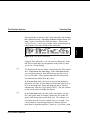
1
This chapter describes the operation of the PC-30 Runtime system. It includes start-up and exit instructions, descriptions of
help subwindows, function keys, and information on various
functions and operations used during Runtime sessions.
8.1 What the Runtime System Does
The Runtime system includes its own real-time multitasking operating system that allows simultaneous execution of control,
graphics, alarming, trending, data logging, file transfer, and I/O
drivers. Its purpose is to execute strategies you create in the PC30 Strategy Builder.
The Runtime system behaves in different ways, depending on
the choices you make when you create the strategy and corresponding displays. Its overall behavior is determined by the parameters you enter into the System Configuration submenu in
the Strategy Builder. (Refer to the SYS CNFG section in Chapter 4: The Strategy Builder.) Some of the system parameters
can be changed during Runtime and some cannot.
Security levels are also set for specific functions in the System
Configuration submenu and determine how much accessibility
operators have during Runtime. Many standard functions can
be invoked at any time during Runtime. You enter commands
and data using the keyboard or the mouse, which is on functional when enabled in the Strategy Builder.
PC-30 User’s Manual
8-1
Runtime
8 The Runtime System
What the Runtime System Does
☞
The Runtime System
The following files are used by the Runtime system:
Strategy Files
4/23/93
<strategy>.CFG
<strategy>.DB
<strategy>.CI
<strategy>.CA
<strategy>.MDB
<strategy>.XDB
Device Driver Files (for each installed driver)
<driver>.MNU
<driver>.DES
<driver>.DRV
Display Files
Option Files
<option>.OPT
8.1.1
EMS & XMS
Runtime
Support
8-2
PC-30 provides support for expanded memory (EMS) and extended memory (XMS) during Runtime sessions. The EMS support is designed to function with EMS memory managers that
conform to the LIM 4.0 format. XMS support is provided for
XMS memory managers conforming to Microsoft Corporation’s
DOS Version 2.0 specification.
PC-30 User’s Manual
RG-GA3-030-005
BOOT.GSP (boot-up display)
*.GSP (system subwindow files)
<file name>.GRP (user-created displays)
☞
What the Runtime System Does
PC-30 automatically recognizes the presence of any installed expanded and/or upper and extended memory and incorporates it
into Runtime operations, making more system memory available for the applications that require it. The amount of system
memory that is made available depends on what PC-30 is capable of placing into expanded and/or upper and extended memory.
Certain buffers, drivers, and options are placed into expanded
and extended memory. Buffers that can be loaded into expanded memory during Runtime include:
• Trend buffer
• Alarm buffer
• History Replay buffer
• Connection buffer
PC-30 detects upper and extended memory during the Runtime
start-up, implements XMS and uses it to store the following
items:
• Strategy database
• Subwindow display
• Other miscellaneous items
PC-30 User’s Manual
8-3
Runtime
The Runtime System
What the Runtime System Does
PC-30 integrates the available expanded memory into frames
and pages that are swapped during the various Runtime operations. During the Runtime start-up operation, available upper
and extended (high) memory is detected and its size is reported
on the screen.
Each EMS frame consists of four 16K pages, allowing 64K of
EMS memory for each frame. The number of EMS frames
available to the Runtime system depends on the amount of EMS
memory in your system. During the Runtime start-up process, a
message appears indicating the number of EMS frames available and the address of the first page.
☞
4/23/93
☞
The Runtime System
Refer to Appendix F: EMS and XMS Memory Support for more
information on the incorporation and use within EMS and XMS
memory.
Shared File
Support
Beginning with Runtime version 5.0, Runtime files can be
shared across a network. This feature is used in conjunction
with the DOS SHARE.EXE utility which allows files to be
viewed by a remote application while Runtime still has the
file(s) open. Shared Runtime files include alarm logs, history
files, trend data, etc.
The Runtime files logged to a shared node can be viewed by
the PC-30 List and History Replay functions as well as text editors that support shared file access (e.g. LIST and EDIT). Refer
to the Shared File Support section of Chapter 3: Before You Begin for more information regarding the features and limitations
of file sharing.
8-4
PC-30 User’s Manual
RG-GA3-030-005
8.1.2
Important!
Hint
What the Runtime System Does
The DOS file sharing-utility (SHARE.EXE) must be
installed on the PC executing PC-30 Runtime
version 5.0. If the file-sharing utility is not installed,
Runtime will abort execution during initialization.
Refer to the DOS Technical Manual for information
on installing SHARE.EXE.
The SHARE.EXE file-sharing utility remains active on the PC
until the PC is turned off. Hence, SHARE.EXE must be invoked
every time the PC is turned on. It is suggested that
SHARE.EXE be put in the AUTOEXEC.BAT file of the PC
executing PC-30 Runtime.
8.1.3
Runtime
Open Files
The number of open files that Runtime can maintain at any one
time is determined by the FILES= statement in the PC’s CONFIG.SYS file. These files include alarm logs, history files,
trend data, etc. The minimum and maximum number of open
files is 55 and 250 respectively. Refer to the Modifying or Setting up a CONFIG.SYS File in Chapter 2 for information regarding the FILES= statement.
PC-30 User’s Manual
8-5
Runtime
The Runtime System
Requirements
The Runtime System
Before you can use the Runtime system, you must have a completed strategy (a set of application-specific displays is optional). To monitor or control a process effectively, you should
understand the overall process and know what the goals and responsibilities are.
The displays designed by the developer within the Display
Builder help the operator understand and interface to the process. The operator may also need some additional written or verbal guidelines from the developer.
Reminder
8-6
The installation requirements for the Runtime system are included in the standard Installation operation. These installation
procedures are described in Chapter 2: Installation. Be sure
you complete the necessary installation requirements before
starting Runtime operation.
The DOS SHARE.EXE file-sharing utility must be
installed on the PC executing PC-30 Runtime.
PC-30 User’s Manual
RG-GA3-030-005
☞
4/23/93
8.2 Requirements
The Runtime System
Runtime Basics
This section describes the basic start-up and operating procedures necessary to begin using the Runtime system. Details on
each of the individual functions and operations available in the
Runtime system are described later in this chapter.
8.3.1
Starting a
Runtime
Session
Starting the Runtime system is performed from the DOS prompt
in the directory that contains the strategy to be executed.
To initiate a Runtime session, perform the following steps:
1. Use the DOS CD\ (C hange D irectory) command to move
into the directory that contains the strategy to be executed.
2. At the DOS prompt, type:
Type: runtime <strategy>↵
where strategy is the name of the strategy created in the
Strategy Builder.
3. The Runtime boot-up display appears as shown in Figure 8.1.
☞
PC-30 User’s Manual
The first page of the Help subwindows also appears on the
screen if the Startup Subwindow field in the SYS CNFG
System Parameters submenu is enabled (default setting).
Setting this field to DISABLED inhibits this subwindow.
The Help subwindow can be invoked by pressing the [?]
key.
8-7
Runtime
8.3 Runtime Basics
Runtime Basics
The Runtime System
4/23/93
Main
Window
VERSION 5.0
ABB Kent-Taylor
Message
Line
:F1:
:F3:
:F6:
:F8:
Operator Messages
Figure 8.1
Note
8-8
HELP SYSTEM
Display Directory
Get Attached Display
Recall Last Display
Tag Sort
:F2:
:F4:
:F7:
Page 1
Tag Details
Alarm Summary / ACK
System Trend
Alarm Alert Messages
Default boot-up display (BOOT.GSP)
The boot-up display that you see may be different
from that shown in the Figure 8.1, since the design
of a start-up display can be altered specifically for
your application. Additionally, the contents of the
Help subwindows can be altered (with the
KEYHELP utility) to reflect any key assignment
changes made via Key Macros.
PC-30 User’s Manual
RG-GA3-030-005
Subwindow
The Runtime System
Runtime Basics
Runtime Command Line
When invoking the Runtime environment for strategy execution, you can specify additional arguments that instruct PC-30
to perform various operations. As mentioned in the previous
section, the syntax for the Runtime command line is:
Runtime
runtime <strategy>↵
where strategy is the name of the strategy you created in the
Strategy Builder.
The Runtime system also supports these additional arguments
that can be included in the Runtime command line:
runtime <strategy> [start-up display] [-keyboard override]
where the meaning of each argument is defined in the following
paragraphs:
strategy
The strategy argument is required at all times in
conjunction with the runtime command. This argument
indicates the name of the control strategy to be executed in
the Runtime environment.
[start-up display]
The start-up display argument allows you to indicate the
name of a specific display (GRP file) to be used as the
Runtime boot screen instead of the standard BOOT.GSP
display. The display file name entered in this argument
should not include the .GRP extension.
PC-30 User’s Manual
8-9
Runtime Basics
The Runtime System
The -keyboard override argument allows you to force
PC-30 to expect your keyboard to function as a specific
keyboard type. Normally, PC-30 automatically determines
the type of system keyboard during the Runtime start-up
procedure. This argument should only be necessary for
computers that have incompatible keyboards when using
previous Runtime versions.
For example, if you had an 83/84 key keyboard and wanted to
bring up a the display file START.GRP as the boot screen for a
strategy named PROCESS, you would enter the following command from at the DOS prompt:
4/23/93
[-keyboard override]
Non-Standard Keyboard Support
During the Runtime start-up procedure, PC-30 implements a
routine that looks for the type of keyboard hardware being used
and automatically configures itself for that type of keyboard activity during the Runtime session.
In unusual instances where your system’s keyboard does not respond within the Runtime environment, you can force PC-30 to
look at your keyboard as a standard keyboard type. This is accomplished using the [-keyboard override] argument in the Runtime command line.
8-10
PC-30 User’s Manual
RG-GA3-030-005
Type: runtime process start -x ↵
The Runtime System
The syntax of the [-keyboard override] argument is:
-<k>
-e<k>
for 83/84 key keyboards (XT’s)
for 101/102 key keyboards (AT’s and above)
where k is replaced by the type of computer being used. The
valid entries for k is shown below.
P
X
A
3
5
PC
PC-XT
PC-AT
PS/2 Model 30
PS/2 Model 50
For example, if you had a 101/102 key type keyboard connected to a PS/2 Model 30 and need to force PC-30 to look at it
that way when executing the BATCH strategy, you would enter
the following Runtime command line at the DOS prompt:
Type:
Caution
runtime batch -e3 ↵
This argument should only be necessary for
computers that have incompatible keyboards when
using previous Runtime versions.
All other
computers should not specify this override
argument unless instructed by Technical Support.
PC-30 User’s Manual
8-11
Runtime
☞
Runtime Basics
Runtime Basics
The Runtime System
8.3.2
☞
The functions and operations that are available during each Runtime session are controlled by security levels. Various operations require specific security levels to be enabled before they
can be performed, e.g. entering process values into Data Entry
fields, toggling strategy blocks between Auto and Manual
modes, etc.
The PASS WORD section in Chapter 4: The Strategy Builder
describes the functions and operations that can be performed by
each security level. It also describes how to setup individual users with assigned security levels that they must enable before
they can perform security protected operations during Runtime.
4/23/93
Security Levels
After the Runtime system is booted, the operator using the system should enable his/her security level before attempting to perform any Runtime functions. The [Alt-P] Password-Security
subwindow shown in Figure 8.2 allows each operator to enable
his/her assigned security level.
1. Press the [Alt-P] key combination to access the Password-
Security subwindow (Figure 8.2).
Figure 8.2
8-12
Password-Security subwindow
PC-30 User’s Manual
RG-GA3-030-005
To logon and thus enable the assigned security level, perform
the following steps:
The Runtime System
Runtime Basics
3. When your password is entered successfully, your name appears in the Current Owner field and your security level
appears in the Current Security Level field. For more information on security levels, refer to the PASS WORD section in Chapter 4: The Strategy Builder.
Note
☞
Note
Your password must be entered exactly as it was
initially recorded with the same upper and
lowercase letters.
If your security level is not
enabled, the Default security level defined for the
strategy is the only level enabled.
Once you successfully log on, you can change your default security level and your password by typing the desired settings into
the Security Level and New Password fields respectively. The
default security level can be changed to a level no higher than
your assigned level. Save your new password or security level
by pressing the standard [Alt-C] (or [Alt-N]) key combination
to checkpoint the database.
The Node Name field in the Password-Security
subwindow (Figure 8.2) allows you to logon/logoff
remote nodes on a PC-30 Network system. Refer
to the Network option’s User’s Guide for additional
information on node security.
PC-30 User’s Manual
8-13
Runtime
2. Using the [Tab] key (the [Shift-Tab] key combination allows you to move backwards) or the mouse, select the Password to LOGON field then type in your Runtime password.
Runtime Basics
The Runtime System
8.3.3
☞
When you finish working in Runtime, your method of exiting
depends on your security level.
You can exit directly to DOS if your security level is 3 (engineer) by pressing the standard [Alt-E] key combination. A
prompt appears in the subwindow asking for confirmation to
exit. Pressing the [Y] key followed by pressing the [Enter]
key. If you do not desire to exit the Runtime system at this
time, continue with your next Runtime operation.
4/23/93
Exiting
Runtime
If your security level is less than 3, you cannot exit from the
Runtime system. Only users logged on with a security level of
3 (engineer) terminate a Runtime session.
RG-GA3-030-005
Each time a user logs on or off, the event is recorded in the
Alarm/Event Summary.
8-14
PC-30 User’s Manual
The Runtime System
Runtime Basics
8.3.4
Viewing
Window Areas
Three window areas, as shown in Figure 8.1, are available for
viewing information during Runtime sessions. They are:
The Main Window is the primary display area and is used
for application-specific displays, directories, trend displays,
etc.
Subwindow
The Subwindow area shows different kinds of displays,
some of which you use to control Main Window displays.
The subwindow also shows the algorithm parameters for
each block in the database when the Details for a specific
block are requested.
Message Line
The Message Line is used for displaying various text
messages during a Runtime session. The Message Line
consists of two parts: the Operator Message area and the
Alarm Alert Message area. Operator Messages are
displayed on the left side of the Message Line, Alarm
Alert Messages are displayed on the right.
☞
During a Runtime session, various operations involved with the
process being executed are performed in these areas. When performing an operation in the Main Window or Subwindow areas,
the active cursor should be in that area before attempting the desired operation. The location of the active cursor is usually indicated by a highlighted field in either the Main Window or Subwindow areas.
PC-30 User’s Manual
8-15
Runtime
Main Window
Runtime Basics
The Runtime System
8.3.5
Note
PC-30 provides several different methods for entering data into
the process during a Runtime session. Various procedures can
be used to access the fields that allow data to be entered into
the process. The following paragraphs describe these operations.
It is possible with the use of Key Macro key
assignments that the operation of the keystrokes
defined below are different than their description.
Refer to the respective Key Macro sections in both
Chapter 4: The Strategy Builder and Chapter 7: The
Display Builder for information on how Key Macros
can effect Runtime key assignments.
4/23/93
Entering Data
[Home] Key
[PgUp] & [PgDn] Keys
Use the [PgUp] and [PgDn] keys to page through any
multiple-page screens or subwindows. These include such
system screens as the Alarm/Event Summary in the Main
Window or any Algorithm Parameter subwindow in the
Subwindow area.
8-16
PC-30 User’s Manual
RG-GA3-030-005
Press the [Home] key to move the active cursor from the
subwindow to the main display and back.
The Runtime System
Runtime Basics
Use the [Tab] and [Shift-Tab] keys to move the active
cursor between pick fields in any display, between data
entry fields in an Algorithm Parameter subwindow, and
from one item to another in listing displayed in the Main
Window, such as the Tag Sort, Historian List, or Display
Directory. The [Tab] key allows you to move forward
through selections, the [Shift-Tab] key allows you to
move backward.
When enabled, a mouse can be used in place of the [Tab]
key, see the Using the Mouse section in this chapter for
more information on Runtime mouse operations. Unless
altered by Strategy or Display Key Macros, clicking on a
pick field or subwindow field with the center mouse key
downloads the value of that field’s process variable to the
database. This is equivalent to pressing the [Enter] key
while the field is selected (highlighted).
Note
If a parameter in an Algorithm Parameter
subwindow is configured as external, any data
entered into that field is not entered into the
database.
[Enter] Key
The [Enter] key downloads the data type into the system
into the real-time database. Type the data into subwindow
fields, and data entries and initialized data entry fields in
displays.
PC-30 User’s Manual
8-17
Runtime
[Tab] & [Shift-Tab] Keys
Runtime Basics
The Runtime System
For subwindows, all changes are downloaded into the
database when you press the [Enter] key. For displays,
only the field the active cursor is positioned on can have
its data downloaded when you press the [Enter] key. You
can download all of the data in a display’s fields
simultaneously by pressing the standard [Alt-D] key.
A mouse can be used during Runtime if its functionality is enabled in the Strategy Builder’s Options icons for the strategy being executed. The mouse can be used in any Main Window display or subwindow to select a pick field.
4/23/93
8.3.6
Using the
Mouse
8.3.7
Accessing
On-Line Help
8-18
The PC-30 Runtime system provides Help subwindows that define the standard key assignments available. These key assignments are based upon the standard Key Macro assignments that
are initially set for all Runtime operations. If Strategy- and/or
Display-based Key Macros are incorporated into a strategy or
display, the assignments made by those Key Macros override
those displayed in the standard Help subwindows.
PC-30 User’s Manual
RG-GA3-030-005
Based on the Cursor Off Delay parameter set in the Mouse Option submenu, the mouse cursor stays on the Runtime screen
while it is actively moving. If the mouse cursor remains idle
for a length of time specified in this Cursor Off Delay parameter, it disappears until the next time it is moved. Refer to the
Enabling the Runtime Mouse section of Chapter 4: The Strategy
Builder for more information on how to enable the Runtime
mouse for individual strategies.
The Runtime System
Runtime Basics
Standard Help Subwindows
The Help subwindows provides a quick on-line reference for
functions and operations that can be performed in the Runtime
system. You can display Page 1 of the Help subwindows any
time by pressing the [?] key. Figure 8.3 shows the six pages of
the standard Help subwindows.
Note
☞
Depending on the location of the “?” character on
your keyboard, it is assumed that you will probably
have to press the [Shift-/] key combination to get
“?” functionality.
While the active cursor is in the Subwindow area and a Help
subwindow is currently visible, the other Help pages can be
scrolled through by pressing the [PgDn] and [PgUp] keys.
Page 1 lists the top-level function keys. You can use the functions attached to many of these keys any time. Certain functions, however, are only operational in certain circumstances.
Page 2 defines the keys which control cursor movement, display
paging, and data entry. Pages 3-6 define the standard system
trace keys and other miscellaneous functions that you invoke
with Alt-key combinations.
PC-30 User’s Manual
8-19
Runtime
You can generate custom Help subwindows via the KEYHELP
utility provided with PC-30. This utility allows you to define
your own Help subwindows that are displayed when the On-line
Help system is called. Your customized Help subwindows can
be configured to reflect any Strategy- and/or Display-based Key
Macros that are in effect.
The Runtime System
Figure 8.3
Standard Help subwindows
The standard assignment of the arrow cursor keys (←,↑,→,↓)
are used for tracing only while the active cursor is in an Algorithm Parameters subwindow. At other times, depending on
Key Macro assignments, the arrow keys can be used for such
operations as invoking application-specific displays.
8-20
PC-30 User’s Manual
RG-GA3-030-005
4/23/93
Runtime Basics
The Runtime System
Runtime Basics
With the KEYHELP utility, you can define a new set of Help
subwindows that depict your key assignments. These new Help
subwindows are invoked by the same [?] operation used by the
standard Help system during Runtime. PC-30 provides the
standard KEYHELP subwindows (HELP1.GSP through
HELP6.GSP) that define the keyboard functions corresponding
to the standard key assignments described in Table 8.1.
The table below shows the KEYHELP Source File used to generate the Standard Help subwindows in Figure 8.3.
Table 8.1 Standard KEYHELP Source File
[F1] = (:F1:,Display Directory).; Display User Diagrams
[F2] = (:F2:,Tag Details).; Get Tag Details
[F3] = (:F3:,Get Attached Display).; Get Attached
Display
[F4] = (:F4:,Alarm Summary / ACK).; Alarm Summary
[F6] = (:F6:,Recall Last Display).; Recall Last Display
[F7] = (:F7:,System Trend).; System Trend
[F8] = (:F8:,Tag Sort). ; Tag Sort
[F9] = (:F9:,Auto / Manual).
[F10] = (:F10:,Remote / Local).
[HOME] = (:Home:,Toggle Between Windows).
[CR] = (:Enter:,Enter Data Field).
[TAB] = (:TAB:,Cursor to Next Field).
[Shift-TAB] = (:Shft TAB:,Cursor to Previous Field).
[PgUp] = (:PGUP:,Previous Page).
PC-30 User’s Manual
8-21
Runtime
KEYHELP Help Subwindows
Strategy- and Display-based Key Macros can be used to redefine the standard key assignments provided in the Help subwindows.
Runtime Basics
The Runtime System
8-22
PC-30 User’s Manual
RG-GA3-030-005
[PgDn] = (:PGDN:,Next Page).
[LEFT] = (::,Up Stream Trace).
[RIGHT] = (:-:,Down Stream Trace).
[UP] = (:UP:,Alternate Up Stream Trace).
[DOWN] = (:DOWN:,Next Page).
[?] = (:?:,Help System).
[Backspace] = (:Backspac:,Delete Character).
[Ctrl-PrtSc] = (:Ctrl-Prt:,Print Screen).
[Shift-F9] = (:Shift-F9:,Draw System Trend).
[Alt-A] = (:Alt-A:,System Parameters).
[Alt-C] = (:Alt-C:,Save Database).
[Alt-D] = (:Alt-D:,Enter All Data Entries).
[Alt-E] = (:Alt-E:,Exit to DOS).
[Alt-F] = (:Alt-F:,File Management).
[Alt-G] = (:Alt-G:,Acknowledge All Alarms).
[Alt-H] = (:Alt-H:,History Replay).
[Alt-J] = (:Alt-J:;Display Alarm Summary).
[Alt-K] = (:Alt-K:,Host Communications).
[Alt-L] = (:Alt-L:, List File Utility).
[Alt-M] = (:Alt-M:,Modem).
[Alt-O] = (:Alt-O:,Profile Directory).
[Alt-P] = (:Alt-P:,Password Security).
[Alt-Q] = (:Alt-Q:,SPC/SQC Replay).
[Alt-R] = (:Alt-R:,Save Recipe Display).
[Alt-S] = (:Alt-S:,System Performance).
[Alt-U] = (:Alt-U:,Run User Task).
[Alt-V] = (:Alt-V:,Display Event Summary).
[Alt-W] = (:Alt-W:,Network File Transfer).
[Alt-X] = (:Alt-X:,Clear Subwindow).
[Alt-Z] = (:Alt-Z:,Network Monitor).
4/23/93
Table 8.1 Standard KEYHELP Source File (cont.)
Runtime Basics
KEYHELP Source File Definitions
Custom Help subwindows are defined in a KEYHELP source
file using any off-line text editor or word processor capable of
handling ASCII files. This source file must be stored in an ASCII text format and have a .HLS extension. The KEYHELP
source file contains a listing of the individual key name, display key na me , and its description .
Once the KEYHELP source file is created, it must be compiled
into a library file using the KEYHELP utility. The KEYHELP
source file consists of a series of statements that define the key
name of each keystroke, how the key displays in the Help subwindow, a description of that key assignment, and any optional
comments. All of the key names that can be used in the source
file statements are defined in Table 4.7: User Definable Keys
in Chapter 4: The Strategy Builder. The syntax of KEYHELP
statements is:
[<key name>] = (<display key name>,<description>).<;comment>
where key name is the actual key or key combination that was
assigned from a Key Macro assignment. This entry must match
the exact syntax (upper and lower case) of the key definition
found in User Definable Keys in Chapter 4: The Strategy
Builder and it must be enclosed in square brackets ([ ]).
The display key name entry is a text string of up to 10 characters that will be displayed in the Help subwindow and is used to
indicate the key or key-combination that is assigned a function.
The display key name,description pair must be enclosed within
parenthesis ( ).
PC-30 User’s Manual
8-23
Runtime
The Runtime System
Runtime Basics
The Runtime System
☞
The KEYHELP source file can contain an unlimited number of
statements in which each successive eight lines is placed into a
single window. The first 8 statement lines make up page 1 of
the Help subwindows, the second 8 lines make up page 2 of the
Help subwindow, and so on. A display key name entry cannot
exceed 10 characters and the description cannot exceed 25 characters. Each source file statement must be terminated by a period (.).
The KEYHELP source file can contain comments. Comments
are preceded by a semicolon (;) and can contain any alphanumeric characters. The length of any single comment is limited
to a single line. When comments are placed on the same line as
a statement, they must appear after the terminating period. The
syntax for a comment string is:
<;alphanumeric comment>
or
[<key name>] = (<display key name>,<description>).<;comment>
8-24
PC-30 User’s Manual
RG-GA3-030-005
The comment entry is any comment string you want to enter
into a source file statement to describe what the definition is accomplishing.
4/23/93
The description entry is a string of up to 25 characters that display next to its corresponding display key name and describes
what function/operation the display key name performs. The
display key name,description pair must be enclosed within parenthesis ( ).
The Runtime System
Runtime Basics
Hint
When you complete your KEYHELP source file (.HLS), copy it
into the PC-30 system directory before compiling it with the
KEYHELP utility. This ensures that the generated .GSP and
.HLP files are found by PC-30 during Runtime start-up.
To compile a KEYHELP source file from the DOS prompt,
type:
Type: KEYHELP <source file name>↵
where the source file name is the name of the .HLS ASCII
source file to be compiled. After KEYMAC successfully compiles the .HLS source file, a screen similar to the one shown in
Figure 8.4 displays. KEYHELP generates the new Help subwindow files, HELPn .GSP, where n is the number of pages of Help
subwindows available.
PC-30 User’s Manual
8-25
Runtime
KEYHELP Operation
The KEYHELP utility accepts the ASCII-formatted .HLS
source file argument and compiles it into a format that is understood by PC-30. After KEYHELP successfully compiles the
source file, it generates the customized .GSP and .HLP Help
subwindow files.
The Runtime System
4/23/93
Runtime Basics
Note
8-26
A sample KEYHELP compilation screen
During compilation, the KEYHELP utility also
generates corresponding .HLP files. These files
currently are not used by PC-30, but they should be
maintained for later Help system enhancement
support.
PC-30 User’s Manual
RG-GA3-030-005
Figure 8.4
The Runtime System
The .HLS KEYHELP source file must be in an
ASCII text format.
If you are using a word
processor to generate your .HLS file, make sure it
can generate (convert) files into an ASCII format.
Files that are not in an ASCII format do not compile
properly with the KEYHELP utility. Refer to your
word processor’s documentation to determine how it
generates ASCII text files.
Runtime
Reminder
Runtime Basics
The last line in your KEYHELP source file must
contain a “CR” character (created by pressing the
[Enter] key) at the end of the line. Failure to place
the “CR” character at the end of the last line results
in an error when you attempt to compile the source
file.
Hint
Use the DOS TYPE command to determine if the .HLS file is in
an ASCII format. If normal alphanumeric characters (for
example, K, p, 4, &, /, etc.) are displayed on the screen, the file
is in ASCII format. If control and/or graphic characters appear
on the screen, the file is not in ASCII format and will not
compile with KEYHE LP properly. From the DOS prompt:
Type: type <file name>.HLS
PC-30 User’s Manual
8-27
Runtime Basics
The Runtime System
KEYHELP Error Messages
The following list contains the possible error messages and their
causes that are posted by the KEYHELP utility.
’,’ expected
’.’ expected
A statement was encountered that did not contain the
required period (.) terminator. All KEYHELP statements
are required to end with a period (.). If a comment is
included in a statement line, the comment cannot be placed
before the statement’s period.
4/23/93
KEYHELP expects the display key na me and its
description to be separated by a comma (,).
’=’ expected
’[’expected
KEYHELP encountered a phrase it determined was a key
na me that did not begin with an open bracket ([). All key
na me specifications must be enclosed by square brackets.
Only the key names listed in the User Definable Keys in
Chapter 4: The Strategy Builder can be used in the key
name definition part of a statement.
8-28
PC-30 User’s Manual
RG-GA3-030-005
KEYHELP encountered a parenthesis before the equal sign
(=) equator. KEYHELP requires the equal sign (=) to be
used to equate a key name to its display key na me and
description .
The Runtime System
Runtime Basics
8.3.8
The standard function key assignments listed in the standard
Help subwindows enable you to perform frequently used PC-30
operations with a simple keystroke. Some keys have more than
one function and require that you press the [Alt] key in combination with an function key to perform the desired operation.
Some combinations, like [Shift-] function key combinations,
may perform different operations based upon the task or subwindow it is being exercised on. Table 8.2 defines the standard
function keys and key combinations are standard throughout the
Runtime system (provided they are not overridden by Key
Macro assignments):
Table 8.2 Standard function key operations
PC-30 User’s Manual
Key
Function
Use
F1
Call up the directory of
displays
Call up a specific display
Anytime
When the Directory
Display is on the screen
and you tab to the
Display Name field
F2
Call up an Algorithm
subwindow menu
Call up an Algorithm
subwindow
Anytime
F3
Call up the display attached
to a block in the strategy
When the active cursor is
in an Algorithm
subwindow or on a PPT
F4
Call up the Alarm/Event
Summary
Anytime (when the
Alarm/Event Summary is
not already displayed)
When the active cursor is
on a data field in a
display or on any Alarm
8-29
Runtime
Using the
Function Keys
The Runtime System
8-30
Function
Use
F4
Acknowledge a specific
alarm
When the active cursor is
on an alarm line in the
Alarm/Event Summary
F4
Acknowledge the most
recent alarm
When the summary is
being displayed and the
cursor is in the
subwindow area
F6
Recall the last
application-specific display
Anytime
F7
Call up the Trend or Plot
window
Anytime
F8
Call up the Tag Sort window
Anytime
F9
Toggle Auto/Manual (output)
Whenever an algorithm
subwindow is displayed
or while the active cursor
is on a PPT
F10
Toggle Remote/Local (set
point)
Whenever an algorithm
subwindow is displayed if
a remote set point was
enabled for the algorithm
(in the Strategy Builder)
or while the active cursor
is on an appropriate PPT
Alt-A
System Parameters
subwindow
Anytime
Alt-C
Checkpoint (save) the
database
Anytime
Alt-D
Download all Data Entry
values
Anytime
Alt-E
Exit Runtime
Anytime (requires the
correct password level)
Alt-F
File Management
subwindow
Anytime
PC-30 User’s Manual
4/23/93
Key
RG-GA3-030-005
Runtime Basics
Runtime Basics
Key
PC-30 User’s Manual
Function
Use
Alt-G
Acknowledge all alarms
Anytime
Alt-H
History Replay subwindow
Anytime
Alt-J
Display Alarm Summary
Anytime
Alt-K
Host Communication
subwindow
Anytime provided the
option has been installed
Alt-L
List File Utility
Anytime
Alt-M
Modem Communications
subwindow
Anytime provided the
option has been installed
Alt-O
Profile Directory
Anytime provided the
Setpoint Profiler option
has been installed
Alt-P
Call Up the Password
Security window
Anytime
Alt-Q
SPC/SQC subwindow
Anytime provided the
option has been installed
Alt-R
Save recipe display to disk
Anytime provided an
operator display is in the
Main Window
Alt-S
System Performance
subwindow
Anytime
Alt-U
Execute the User Task
Anytime provided the
option has been installed
and configured
Alt-V
Display Event Summary
Anytime
Alt-W
Network File Transfer
subwindow
Anytime provided the
option has been installed
Alt-X
Clear Subwindow area
Anytime
Alt-Z
Network Monitor
subwindow
Anytime provided the
option has been installed
8-31
Runtime
The Runtime System
Operation of the Runtime System
The Runtime System
Displaying
Multipage
Directories
Long directories can be displayed in a multiple-page format during Runtime. Using the appropriate function keys, you can invoke a directory screen that identifies the files available for the
respective operation, e.g. [F1] for a Display directory, [F8] to
display a Tag Sort directory, etc. If there are more files than
can fit in a single directory screen, the directory can be scrolled
a page at a time. Press the [PgDn] key to view the next directory screen and press the [PgUp] key to view a previous directory screen.
4/23/93
8.3.9
8.3.10
Beginning with PC-30 Runtime version 5.0, a screen saver can
be enabled for the Runtime system. The Runtime screen saver
causes the screen to “black out” when there is no keyboard or
mouse activity for a user specifiable amount of time. When the
screen saver activates, any mouse or keyboard action restores
the screen that was displayed when the screen saver activated.
The screen saver is enabled and configured in the SYS algorithm block configuration menu in the Strategy Builder.
8.4 Operation of the Runtime System
Once the runtime <strategy> command line is executed from
the DOS prompt, the strategy included in this command line begins its execution. While the strategy is executing, any of the
functions and/or operations available within PC-30 can be performed (provided the strategy lends itself to each particular function or operation). The sections that follow describe the necessary procedures and options involved when performing the functions and operations in the Runtime system. Some functions
and operations have several methods for accomplishing the
same task. If so, each method is identified and described.
8-32
PC-30 User’s Manual
RG-GA3-030-005
Runtime
Screen Saver
The Runtime System
System Parameters
During strategy configuration in the Strategy Builder, the strategy developer specifies a number of parameters that affect the
overall behavior of the strategy during Runtime. These parameters are described in the SEL Function, System Configuration
section in Chapter 4: The Strategy Builder.
You can change some of these parameters during Runtime, using the System Parameters subwindows shown in Figure 8.5.
5.00
Figure 8.5
System Parameters subwindows
To invoke and make changes to the available Runtime system
parameters perform the following steps.
1. Press the [Alt-A] key combination to display the System Pa-
rameters subwindow. If necessary, use the [Home] key to
move the active cursor into the Subwindow area.
2. Make your change by tabbing to the appropriate field and
typing the new data into the field.
3. Press the [Enter] key to save the entered data.
PC-30 User’s Manual
8-33
Runtime
8.5 System Parameters
System Parameters
☞
The Runtime System
The System Parameters subwindows contains the following
fields:
Page 1
This parameter controls the system’s alarm annunciator
(speaker). Entering Y enables alarms to be sounded over
the computer’s speaker where higher pitched tones are
generated for higher priority alarms. Entering N disables
the annunciator.
4/23/93
Alarm Annunciator
Alarm Print?
This parameter determines whether alarms are printed to
the configured printer as they occur. Enter Y to print
alarms on the alarm printer, which is specified in the
Strategy Builder through the System Configuration –
ALRM CNFG’s Alarm Printer Port parameter. Entering
N inhibits the printing of alarms.
This field corresponds to the Alarm Squelch Level set in
the ALRM CNFG Logger Parameters submenu (Strategy
Builder). This parameter lets you define a level of
suppression for all process alarms. This acts as the
“master” squelch level for all alarms. The value (0 to 9)
entered in this field determines which alarms are
suppressed. All alarms with a priority less than the
squelch level are not displayed, sounded, printed, or logged
to disk.
8-34
PC-30 User’s Manual
RG-GA3-030-005
Global Squelch Level
System Parameters
Sub-squelch levels also exist for alarm annunciating,
printing, displaying, and logging to disk. The alarm
priority must be greater than or equal to the Global Alarm
Squelch level and greater than or equal to the sub-squelch
level for the particular action (printing, displaying, etc.) in
order for the action to take place. The sub-squelch level
fields are described below.
Display Squelch (DSP)
This squelch level determines if the alarm will appear on
the Alarm/Event Summary screen.
Disk Squelch (LOG)
This squelch value determines if the alarm will appear in
the alarm log file. This only applies if the Alarms to
Disk ? parameter is set to Y .
Printer Squelch (PRN)
This squelch value determines if the alarm will be sent
to the printer. This only applies if the Alarm Print ? parameter is set to Y .
Annunciator Squelch (ANC)
This squelch value determines if the alarm will sound.
This only applies if the Alarm Annunciator ? parameter is set to Y .
Screen Update Period
This parameter lets you override the default Display
Update Period setting defined in the SYS CNFG submenu
in the Strategy Builder. You may set this period at preset
values of .1, .25, .5, 1 , 2 , 3 , 4 , or 5 seconds. Longer times
leave more computing resources for disk-related operations
and give less information to the operator.
PC-30 User’s Manual
8-35
Runtime
The Runtime System
System Parameters
The Runtime System
Scan I/O
It is possible to turn on the I/O Scanner previously turned
off automatically based upon a digital event. During the
configuration of the strategy in the Strategy Builder, the
developing engineer needs to incorporate a SYS block into
the strategy. By connecting the controlling digital variable
to the SYS block’s SCAN input, when that digital goes
true (logical 1) the SYS block turns the I/O Scanner on.
4/23/93
This is a display-only field that displays Y or N . On
Demand displays as N . The I/O Scanner must be turned
on (Y) in the Strategy Builder’s SYS CNFG submenu in
order to access any I/O hardware installed. With the
scanner turned off (N), you can run a strategy in
simulation mode for test purposes.
This parameter indicates whether alarms are logged to a
disk file. This field accepts a value of Y or N . If Y ,
alarms are written to files on the hard drive. The file
LOGnn.TXT is created, where nn is a number from 0 to
99. The file is closed either when Runtime is exited or if
this function (and Events to Disk) is turned off by
entering a N in this field. The next time alarm logging
starts, the LOGnn.TXT file number increments. Note that
the alarm file name can be changed from LOG in the
Strategy Builder’s ALRM CNFG File Parameters submenu.
Plot (Y) or Trend (N) ?
This parameter allows you to specify how the PC-30
System Trend function is displayed. Enter Y for Plot
mode or N for Trend mode.
8-36
PC-30 User’s Manual
RG-GA3-030-005
Alarms to Disk?
The Runtime System
System Parameters
Events Print?
Events to Disk?
This parameter allows you to specify if Operator Events
are logged along with alarms to the disk file. Enter Y or
N . Events are logged to the same file as alarms,
LOGnn.TXT (or the file defined in the Strategy Builder’s
ALRM CNFG submenu).
Scan Periods
This is the interval at which PC-30 scans the four serial
ports for I/O communications. These values are initially
set up in the Strategy Builder’s COMM CNFG submenu.
(Note that the communication scan time set in COMM
CNFG should be set to scan twice as fast as the fastest
device block (i.e. block processor) or I/O block scan rate
associated with it.) Defining different scan period values
during Runtime requires that the respective serial port be
set to INSTALLED in the COMM CNFG submenu in the
Strategy Builder.
The furthest field to the left represents the COM1: scan
period field, COM2: is to the right of COM1:, and so on.
The valid values for these four scan period parameters are
0.05 through 99 seconds. Out-of-range entries are
automatically rounded to the nearest legal value.
PC-30 User’s Manual
8-37
Runtime
This parameter allows you to specify in Operator Events
items to be logged, along with alarms, to the configured
alarm printer. Enter Y to print operator events to the alarm
printer (defined in the Strategy Builder’s ALRM CNFG
submenu) or N to inhibit event printing.
System Parameters
The Runtime System
Disable Tabbing to Picks?
4/23/93
This parameter lets you define whether pick fields can be
tabbed to in operator displays or system subwindows.
Enter Y to disable tabbing to pick fields (process points
cannot be accessed). Enter N to enable pick field tabbing,
thus allowing the operator to tab to (select) a process point
and access the process variable within that process point.
Page 2
Version
The version of PC-30 Runtime presently operating.
Time
This parameter allows you to enter a new time setting for
the Runtime session. The fields available consist of: Hr ,
enter the 24-hour value (0 to 23) Min, enter the minutes
value (0 to 59) Seconds, enter the seconds value (0 to 59).
This parameter allows you to enter a new date setting for the
Runtime session. The fields consist of: Day; enter the
desired calendar day (1 to 31), M o; enter the desired calendar
month (1 to 12), Year; enter the desired calendar year.
Memory Left:
This parameter actually includes two fields: LOW and
HIGH which display how much corresponding RAM
memory is available for Runtime operations. The LO W
field displays how much conventional memory is available.
The HIGH field displays how much upper and high
memory is available.
8-38
PC-30 User’s Manual
RG-GA3-030-005
Date
The Runtime System
System Parameters
Database Caching
The following parameters for the Database Caching feature are
implemented in PC-30 Version 4.0 and higher. For more information on any of these parameters, refer to the Database Caching section in Chapter 3. All of these parameters are view-only;
you cannot change them from here.
Runtime
☞
I/O Block Caching
Shows the status of the I/O Block Caching System
Configuration parameter. 0 = OFF / 1 = ON
Distributed
Shows the status of the Distributed Block Caching System
Configuration parameter. 0 = OFF / 1 = ON
DB Cache Size
Shows the current System Configuration setting for the
total cache buffer size (in Kbytes).
Cache Block Size
Shows the current System Configuration setting for the
total cache block size (in bytes).
Cache Total
Shows the current total amount of the cache buffer in use.
Largest Hole
Depending on the Cache Block Size setting, more or less
memory segmentation occurs, leaving holes in the Cache
memory buffer. Largest hole size gives you an indication
of how efficiently the buffer is being used. The Units of
PC-30 User’s Manual
8-39
Tag Sort Function
The Runtime System
size are in Cache Blocks. For example, if the largest hole
value is 10 and Cache Block Size is 16 bytes, the largest
hole is 160 bytes (refer to Database Caching in Chapter 3).
Cache Used
% Cache Used
Shows the current percentage (% of total) of the cache
buffer in use.
4/23/93
Shows the actual amount of cache buffer memory in use.
8.6 Tag Sort Function
The Tag Sort function provides a sorted display of block tag
names from the strategy that is currently being executed. Figure 8.7 shows an example of a what a typical Tag Sort Display
looks like.
1. Press the [F8] key. The Tag Sort Menu subwindow appears
in the Subwindow area of the screen as shown in Figure 8.6.
Figure 8.6 Tag Sort Menu subwindow
2. Use the [Tab] key (or the mouse if it is enabled) to move
the cursor from one field to the next. If necessary, press the
[Home] key to place the active cursor in the Subwindow
area.
8-40
PC-30 User’s Manual
RG-GA3-030-005
Perform the following steps to use the Tag Sort function.
(These steps assume that you invoked the Runtime system and a
strategy is being executed.)
Tag Sort Function
Runtime
The Runtime System
Figure 8.7
Tag Sort Display sample
3. With the SORT TYPE field selected (highlighted), specify
the algorithm type that you want to display. You can enter
one of the following:
• “all” to display all algorithm types
• “alarm” to display all blocks currently in alarm
• a specific algorithm type, such as PID, ADD, AIN, etc.
4. With the TAG NAM E field selected, specify which tags to
display according to their defined tag names, e.g. all tags beginning with the letter F, etc.
You can use an asterisk (*) as a wildcard character, just as
you do in DOS. For example, * displays all tag names, S*
displays all tag names beginning with S, and DRUM* displays all tag names beginning with DRUM.
PC-30 User’s Manual
8-41
Tag Sort Function
The Runtime System
5. After both the SORT TYPE and TAG NAM E fields are de-
Figure 8.8
Hint
8-42
Tag Sort Display example with S* tags in alarm
While a Tag Sort Display is in the Main Window, it is possible,
with the proper security level enabled, to produce the Tag
Details subwindow for any Tag entry by selecting the desired
tag with the active cursor then pressing the [F2] key.
PC-30 User’s Manual
RG-GA3-030-005
4/23/93
fined, press the [Enter] key to display the Tag Sort Display
for block tag names that match those specifications.
Figure 8.8 shows a display of all tags in alarm beginning
with the letter “S”.
The Runtime System
Tag Sort Function
8.6.1
The Tag Sort Function operates differently for Intelligent I/O
device blocks. An intelligent I/O block contains input and output points.
To use the Tag Sort Function for Intelligent I/O blocks, perform
the following steps:
1. Press the [F8] key. The Tag Sort Menu subwindow appears
in the Subwindow area of the screen as shown in Figure 8.7.
2. Use the [Tab] key (or the mouse if it is enabled) to move
the cursor from one field to the next. If necessary, press the
[Home] key to place the active cursor in the Subwindow
area.
3. With the SORT TYPE field selected (highlighted), specify
the algorithm type that you want to display. You can enter
one of the following:
• “all” to display all algorithm types
• “alarm” to display all blocks currently in alarm
• a specific algorithm type, such as PID, ADD, AIN, etc.
4. With the TAG NAM E field selected, specify which tags to
display according to their defined tag names, e.g. all tags beginning with the letter F, etc.
You can use an asterisk (*) as a wildcard character, just as
you do in DOS. For example, * displays all tag names, S*
displays all tag names beginning with S, and DRUM* displays all tag names beginning with DRUM.
PC-30 User’s Manual
8-43
Runtime
Intelligent I/O
Blocks
Tag Sort Function
The Runtime System
5. After both the SORT TYPE and TAG NAM E fields are de-
fined, press the [Enter] key to display the Tag Sort Display
for block tag names that match those specifications.
Figure 8.9
8-44
Intelligent Device Path List screen
PC-30 User’s Manual
RG-GA3-030-005
Device Path List screen displays (Figure 8.9). This screen
lists the I/O point(s) written or read to for an Intelligent I/O
device.
4/23/93
6. Highlight a tag name and press [F2]. The Intelligent I/O
The Runtime System
Algorithm Subwindows
7. Press [F2] and a subwindow displays at the bottom of the
Runtime
screen. This subwindow displays the path name and various
parameters for the Intelligent I/O block.
Figure 8.10 Intelligent I/O Path Name subwindow
8.7 Algorithm Subwindows
An Algorithm subwindow (invoked by the Tag Details function) displays the current values of parameters and variables
within any block in your strategy. These subwindows also provide data entry fields which allow you to change variable/parameter values in the database. Because of the possible conditions that could occur by inadvertently changing process values,
Algorithm subwindows are protected by security levels.
Depending on the security level that is currently enabled, various levels of subwindows can be displayed. With level 0
(View-only) and level 1 (Operator) enabled, Algorithm subwindows cannot be displayed. Certain algorithm blocks have more
than one page of subwindows. If your system is set to security
level 2 (Technician), you can only enter values into the first
page of each Algorithm subwindow. At security level 3 (Engineer), you can enter values on all pages. Refer to Chapter 6:
Algorithms for a description of each parameter and variable displayed in its Algorithm subwindow(s).
PC-30 User’s Manual
8-45
Algorithm Subwindows
The Runtime System
Figure 8.11 Sample PID algorithm subwindow
4/23/93
Figure 8.11 shows an example of the first page of the PID algorithm’s Tag Details subwindow. This example illustrates the
common characteristics of Algorithm subwindows that are invoked via the Tag Details function.
8.7.1
Algorithm subwindows include both data entry and process
point fields for parameters and variables within the respective
block. The data entry fields are highlighted on the screen with
a solid box. Data entry fields are not dynamic; they display the
parameter values at the moment the subwindow was invoked or
the last value entered, if any.
The process point fields appear as text against a black background. These fields are for display only and cannot be tabbed
to and changed. Some data display fields contain static data,
such as the description field, while others contain live data,
such as the out field.
☞
8-46
If a parameter is configured as external (set to E in the block’s
configuration menu in the Strategy Builder) then the data entry
field for that parameter/variable is not active in the subwindow.
You can enter data into its field in the subwindow, but it will
not be downloaded into the database.
PC-30 User’s Manual
RG-GA3-030-005
Algorithm
Subwindow
Contents
Algorithm Subwindows
Most Algorithm subwindows include a bar graph faceplate that
shows the output, input(s), and set point (for controller algorithms) as percentage of span values. The field to the right of
the output bar indicates whether the block’s output is in Auto
mode (A) or Manual mode (M). For a Control algorithms, e.g.
PID, PD, INTG, DGAP, etc., the field to the right of the setpoint bar indicates whether the setpoint source is remote (R) or
local (L).
8.7.2
Invoking
Algorithm
Subwindows
There a several methods available during Runtime to invoke an
Algorithm subwindow. Each method is described in the following paragraphs.
METHOD
➊
If the active cursor is not in a tag name field or data field in a
Main Window display, press the [F2] key. The prompt shown
in Figure 8.12 appears in the Subwindow area. Type the desired tag name in the TAG field and press the [Enter] key.
Figure 8.12 Algorithm subwindow TAG prompt
METHOD
➋
With another block’s Algorithm subwindow already displayed,
use the [Tab] key (the [Shift-Tab] key to move backward) or
the mouse, select (highlight) the TAG field. Type the tag name
of the block to be displayed and press the [Enter] key.
PC-30 User’s Manual
8-47
Runtime
The Runtime System
Algorithm Subwindows
METHOD
The Runtime System
➌
METHOD
➍
With one of the system displays shown below in the Main Window, use the [Tab] key or the mouse, to select (highlight) the
desired tag then press the [F2] key. The corresponding Algorithm subwindow for the selected tag is displayed.
4/23/93
Use the [Tab] key (the [Shift-Tab] key to move backward) or
the mouse to select (highlight) a data entry or process point
field in a Main Window display. (Tabbing to pick fields may
be disabled in the Strategy Builder.) Press the [F2] key. The
Algorithm subwindow associated with the variable connected to
the corresponding field is displayed.
METHOD
➎
Using the trace method, you can overwrite the currently displayed Algorithm subwindow with the subwindow for the next
block to which it is connected upstream or downstream. In the
event that multiple connections are made to a block’s output,
the trace method displays the Algorithm subwindow of the first
connection made.
8-48
PC-30 User’s Manual
RG-GA3-030-005
• Tag Sort Display
• Alarm/Event Summary
• Trend and Plot List
• Historian List
Algorithm Subwindows
To Display
Press
a downstream block’s algorithm subwindow to
which the algorithm is sending output
→ key
an upstream measurement block’s algorithm
subwindow
← key
an upstream setpoint block’s algorithm
subwindow
↑ key
Runtime
The Runtime System
8.7.3
Entering/
Changing
Subwindow
Data
For most algorithms, the block’s output can be accessed by first
toggling between Auto and Manual modes. You can only enter
data in the data entry field when the block is in Manual mode.
The field to the right of the output bar indicates the current
mode (A or M).
When entering analog values into a data entry field, the number
may exceed the field size (7 characters). If a number greater
than 9999999 is entered in a field, Runtime attempts to display
the number in scientific notation. If there is not enough space
for scientific notation, the entry appears as ??????? meaning the
number too large for Runtime to handle.
☞
Note
While the active cursor is in a block’s Algorithm subwindow,
you can toggle the block’s output mode (Auto/Manual) by pressing the [F9] key. Auto/Manual mode for an algorithm block
can also be toggled by selecting a pick field in the main window for the desired block and then pressing the [F9] key.
A process point and data entry field associated with
the each block’s OUT variable appear to the right of
the out bar graph, (see Figure 8.11 shown previously).
PC-30 User’s Manual
8-49
The Runtime System
Setpoint modes for Control algorithms, e.g. PID, PD, INTG,
DGAP, etc., can be toggled between Remote (R) and Local (L)
modes by pressing the [F10] key while the active cursor is
either in the block’s Algorithm subwindow or on pick field in
the Main Window that is attached to the corresponding block.
When the block is in Local mode, you can enter setpoint values
into the corresponding data entry field. When in Remote mode,
setpoint values are controlled by the process.
☞
Remote/Local toggling can only be performed while the block
in question has its REM SETP parameter in the Strategy
Builder’s configuration menu is set to Y .
4/23/93
Checkpointing Database Changes
During Runtime, changes in process variable values and/or system parameters can be saved (checkpointed) at any time by
pressing the [Alt-C] key combination (or [Alt-N]). This operation causes PC-30 to create a new database file that has the
same strategy name, but the extension .NEW is used instead of
.DB. This checkpointed database is used if your computer
should lose power or some other system failure occurs and a
“warm start” is necessary. Refer to the SYS CNFG section of
Chapter 4: The Strategy Builder for information on warm starts.
During strategy development in the Strategy Builder, the strategy developer can also specify to checkpoint (save) the database periodically or have the checkpoint operation trigger automatically based on a digital event. Both methods of checkpointing are accomplished by incorporating a CKPT block into the
strategy. Refer to CKPT block section in Chapter 6: Algorithms for additional information on automatic checkpointing of
the Runtime database.
8-50
PC-30 User’s Manual
RG-GA3-030-005
8.8 Checkpointing Database Changes
The Runtime System
Operator Displays
Using the Display Builder, the process developer can design an
unlimited number of graphic displays for a specific application.
Often the developer designs a main display to illustrate the overall process and a series of other displays to illustrate important
details and/or operations associated with the process. Figure
8.13 shows a sample display.
Figure 8.13 Sample display
PC-30 User’s Manual
8-51
Runtime
8.9 Operator Displays
The Runtime System
Displays can be invoked automatically by the system, based on
external digital events or time. The design engineer specifies
how these displays are invoked using a DISP block in the Strategy Builder. The DISP block is also capable of executing a
Named Macro from a Key Macro library configured into the
strategy being executed. Refer to the DISP section in Chapter
6: Algorithms for more information on how to configure the
DISP block for automatic display calling. The Automatic Execution of Named Macros section in Chapter 4: The Strategy
Builder provides additional information on how the DISP block
can be configured to execute a Named Macro.
4/23/93
Operator Displays
8.9.1
The operator can also invoke any graphic display using several
different methods. These methods are described in the following paragraphs. The last two methods described are contingent
on decisions that the developing engineer makes when using the
Strategy or Display Builder.
METHOD
➊
The most common procedure used for selecting and invoking
operator graphic displays is the Display Directory screen. Pressing the standard [F1] key at anytime during a Runtime session
invokes the Display Directory screen. A sample Display Directory screen is shown in Figure 8.14.
8-52
PC-30 User’s Manual
RG-GA3-030-005
Invoking
Displays
Operator Displays
Runtime
The Runtime System
Figure 8.14 Display Directory screen
With this display in the Main Window area, you can either type
in a display file name from the keyboard into DISPLAY
NAM E field, or you can select a display file from the directory
by pressing the [Tab] key until the desired file is highlighted
(the [Shift-Tab] key to moves the cursor backward). With the
desired file highlighted, press the [F1] key again and that display is placed in the Main Window.
METHOD
➋
When a series of graphic displays are shown in the Main Window, you can recall the last display by pressing the [F6] key.
PC-30 User’s Manual
8-53
Operator Displays
The Runtime System
METHOD
➌
• in an Algorithm subwindow for the block
the block’s tag name in a: Tag Sort Display, Alarm/Event
• onSummary,
Trend and Plot List, or Historian List
4/23/93
Using the Strategy Builder, the design engineer can attach a display to any block in the strategy by entering the desired .GRP
display file name into the DISPLAY field in that block’s configuration menu. During Runtime, an operator can invoke this
attached display by pressing the [F3] key while the active cursor is:
point or data entry field for any variable contained
• onin thea process
block (in any other display)
➍
Using the either Strategy- or Display-based Key Macros, the developing engineer can use a Key Macro assignment to define
any valid key or key combination to invoke a particular display
during Runtime. The DISPLAY Key Macro Operator Interface
Command is used to define any .GRP display file to a valid key
or key combination. The NEXT_PAGE and PREV_PAGE
commands are used to assign display files to the [PgDn] and
[PgUp] keys respectively. When this method is used, the engineer should provide the operator with a window, either as part
of a display or as a reference sheet that explains the display file
assignments.
8-54
PC-30 User’s Manual
RG-GA3-030-005
METHOD
The Runtime System
Operator Displays
8.9.2
A display can include Process Point (PPT), Data Entry (DE), Initialized Data Entry (IDE), and Dynamic Data Entry (DDE)
fields as shown in Figure 8.15. DE and IDE fields are highlighted with a box when the are selected with the active cursor
in the Main Window.
A PPT field is updated periodically (every .1 to five seconds, depending on your configured Display Update Period parameter). This field is also referred to as a “pick field” in some of
the subwindows.
Figure 8.15 Data Fields in a display
PC-30 User’s Manual
8-55
Runtime
Process Point
& Data Entry
Fields
Note
A DE field is not updated while it is in the Main Window. It
displays the value of a variable at the time the display was invoked (or the last value entered, if any). An IDE is similar, except that the value of its variable is initialized in the Display
Builder. That initialized value is downloaded to its connected
process variable when the [Alt-D] key combination is pressed
while the display containing the IDE appears in the Main Window.
IDE values are only downloaded to their connected
process variable when the [Alt-D] key combination
is pressed while the IDE display is in the Main
Window. A DISP block can be used to cause the
contents of all DE and IDE fields in a display to be
automatically downloaded when it (the DISP) block
invokes the display.
If a variable’s value changes during the Runtime
session and a display containing an IDE connected
to that variable is placed in the Main Window, the
value contained in the IDE field may not represent
the actual value of the process variable it is
connected to . You may want to place a PPT along
with the DE and/or IDE field(s) to monitor actual
variable values.
The DDE field combines the function of both the DE and PPT
field into one field. As long as the active cursor is not positioned on the DDE field, the DDE periodically updates and displays the current value of its connected process variable. When
the active cursor is on a DDE field, its value is not updated, but
8-56
4/23/93
☞
The Runtime System
PC-30 User’s Manual
RG-GA3-030-005
Operator Displays
The Runtime System
Operator Displays
data entry can be performed by typing the desired value then
pressing the [Enter] key.
☞
You can move the active cursor to any DE, IDE, DDE, PPT, or
State Field (SF) in a display successively pressing the [Tab]
key until the desired field is selected. The [Shift-Tab] key
combination can also be used to move the active cursor backward. When the active cursor moves to a DE or IDE field, the
field is highlighted in red, indicating that data entry can take
place. When the cursor moves to a PPT, the field is outlined
with a yellow box.
In the Strategy Builder, the engineer can disable the ability to
tab process points so that the cursor moves only between DE
and IDE fields, making it easier to enter data quickly. This can
also be done during Runtime on the second page of the [Alt-A]
System Parameters subwindows.
☞
To enter data into a DE, IDE, or DDE field, tab to the field so
that it is highlighted in red, type in the data from the keyboard,
and press the [Enter] key. To enter all of the data that appears
in every DE, IDE, and DDE in a display simultaneously, type
in all the data into their respective fields and press the [ALT-D]
key combination. All data is downloaded into the database.
PC-30 User’s Manual
8-57
Runtime
With a Security Level 0 (View-only) enabled, these fields cannot be changed. Level 1 (Operator) and Level 2 (Technician)
can change DE fields. Only Level 3 (Engineer) can change and
IDE field.
Recipe Displays
The developing engineer can create recipe displays that include
IDE fields. These IDE fields contain values for specific process
variables that setup the recipe. During Runtime, the recipe data
is downloaded by invoking the recipe display and pressing the
[Alt-D] key combination as described above. PC-30 downloads
all IDE (and any other variable values in display data fields)
and executes the strategy based on those values.
☞
If your system has Security Level 3 (Engineer) enabled, the operator can also change the values in IDE fields. When IDE initialized values are changed they can be saved to the current display file or to a new display file. Pressing [Alt-R] causes PC30 to prompt you for the name of the file (diagram) to save the
recipe display to. The current display file name is shown in
this prompt. Either accept the current name or type in a new
one from the keyboard and press the [Enter] key.
Recipe displays can also be invoked automatically if the engineer configured one or more DISP blocks in the Strategy
Builder. When a display is invoked in this way, the data in
IDE fields may or may not be downloaded into the database
automatically, depending on whether the DISP block’s corresponding RECIPE parameter has been set to Y (yes).
A SYS block can also be incorporated into a strategy to control
the downloading of display data into the database. By connecting a digital into the SYS block’s DNLD variable, when this
digital goes true (logical 1) all data field values in the current
display are downloaded into the database. Refer to the DISP
and SYS sections in Chapter 6: Algorithms for details on how
to setup the DISP and SYS blocks for automatic recipe downloading.
8-58
PC-30 User’s Manual
4/23/93
The Runtime System
RG-GA3-030-005
Operator Displays
The Runtime System
Alarms and Operator Events
PC-30 provides an immediate alert of individual alarms that occur by placing an alarm message at the Message Line in the
lower right corner of the Runtime screen. The Alarm/Event
Summary screen, invoked by pressing the [F4] key, provides a
listing of all alarm conditions as well as operator events, such
as changing the value of a parameter.
Many parameters that affect how Runtime handles alarms and
events are set in the Strategy Builder (ALRM CNFG) and can
be changed during Runtime using the [Alt-A] System Parameters subwindows. Refer to the System Parameters section in
this chapter for more information on alarm/event parameters.
8.10.1
Alarms
Runtime reads certain process variables (data points) based on
how the I/O Scanner parameter is configured in the Strategy
Builder SYS CNFG menu (OFF, ON, ON DEMAND). Points
that are not read cannot have alarming performed on them.
Therefore, points that require alarming should have their respective blocks FUL L SCAN parameter set to Y so that point values will always be read during Runtime.
When using the PC-30 database caching feature, I/O points can
be polled for alarms provided the Alarm Cache option is enabled in the strategy. This option only applies to I/O points that
are connected to device blocks. The scan rate for polling
cached points is specified when the Alarm Cache option is configured and is set independently of the I/O Scanner and block
scan rate. Refer to the Enabling PC-30 options section in Chapter 4: The Strategy Builder for more information regarding the
operation and configuration of the Alarm Cache option.
PC-30 User’s Manual
8-59
Runtime
8.10 Alarms and Operator Events
Alarms and Operator Events
Alarm Squelch Level
The alarm squelch level is initially set in the ALRM CNFG Logger Parameters submenu (Strategy Builder) and can be changed
in the [Alt-A] System Parameters subwindow. The squelch
level (0 to 9) determines which alarms are suppressed. All
alarms with a priority less than the squelch level are not displayed, sounded, printed, or logged to disk.
Sub-squelch levels for alarm displaying, annunciating, printing,
and logging to disk also exist. These are configured in the
ALRM CNFG submenus of the Strategy Builder and can be
changed in the [Alt-A] System Parameters subwindow during
Runtime. If an alarm has a priority that is greater that the
Alarm Squelch Level but is less than the sub-squelch level for
a particular function, that function is not executed.
Alarm Alert Messages
As soon as an alarm occurs, PC-30 displays the alert message
similar to the one shown in Figure 8.16. This message remains
on the screen until the alarm is either acknowledged or another
alarm occurs.
8-60
PC-30 User’s Manual
4/23/93
You can inhibit all system alarms automatically based upon a
digital event. During the configuration of the strategy in the
Strategy Builder, incorporate a SYS block in the strategy. Connect the controlling digital variable to the SYS block’s INHB input variable. When that digital goes true (logical 1) the SYS
block inhibits all system alarms.
RG-GA3-030-005
☞
The Runtime System
Alarm message in the
Message Line
Alarms and Operator Events
Type of alarm
Tag name or description
of block in alarm
Figure 8.16 Sample Alarm Alert Message
Alarm Annunciators
If the annunciator is enabled (via the Strategy Builder’s ALRM
CNFG Annunciator Parameters submenu), the computer generates alarm tones with its speaker. The tone of the annunciator
corresponds to the alarm’s priority. The higher the alarm priority, the higher the pitch of the alarm. To silence an alarm, press
any key on the keyboard. You can toggle the annunciator on
and off through the ALARM ANNUNCIATOR field in the
[Alt-A] System Parameters subwindows.
☞
It is possible to disable the alarm annunciator automatically
based upon a digital event. During the configuration of the
strategy in the Strategy Builder, the developing engineer needs
to incorporate a SYS block. By connecting the controlling digital variable to the SYS block’s ANNC input variable, when that
digital goes true (logical 1) the SYS block disables the alarm annunciator if it is turned on.
PC-30 User’s Manual
8-61
Runtime
The Runtime System
Alarms and Operator Events
The Runtime System
Operator
Events
The Operator Events parameter in the ALRM CNFG Event
Configuration submenu (in the Strategy Builder) controls how
operator events are handled during Runtime. As long as Operator Events is enabled in the Strategy Builder, operator events
are displayed to the Alarm/Event Summary screens ([F4]) during Runtime. In addition, events can be directed to a printer
and/or to disk by means of the Strategy Builder ALRM CNFG
Event Configuration submenu or the [Alt-A] System Parameters
subwindows.
4/23/93
8.10.2
☞
8-62
• acknowledging alarms
• changing a block’s output from Auto to Manual and vice versa
• changing a block’s setpoint from Remote to Local and vice versa
• changing a block’s output, setpoint, and most other parameters
• changing the default security level
• logging on and logging off
• exiting to DOS
Digital alarms generated by the DIN, PDIN, PDIO, AND,
NAND, OR, NOR, NOT, XOR, and CNT blocks can be configured to display as events during Runtime. This is specified in
the ALM->EV T field in the respective block’s configuration
menu. If this field is set to Y, digital alarms show up as events
only. Therefore, alarming functions (annunciating, acknowledging, etc.) cannot be performed on these digital alarms.
PC-30 User’s Manual
RG-GA3-030-005
With operator events reporting enabled at the Strategy Builder
level, the following actions or occurrences during Runtime classify as operator events:
The Runtime System
Alarms and Operator Events
Alarm/Event
Summary
Each time an alarm or operator event occurs during the execution of a strategy, a corresponding message is displayed in the
Message Line on the Runtime screen. In addition to the a message being posted on the screen, each alarm/event that occurs
generates an entry identifying the alarm/event in the Alarm/
Event Summary.
All alarms and events can be viewed by invoking the
Alarm/Event Summary screen (Figure 8.17). This is done by
pressing the [F4] key at any time during a Runtime session.
Pressing the [F4] key causes Page 1 of the Alarm/Event Summary to appear in the Main Window with the active cursor on
the first entry in the list. You can advance the active cursor by
pressing the [Tab] key.
The top bar of the Alarm/Event Summary screen displays the
current time and date in the upper right corner. The upper left
corner displays the date of the alarm or event selected by the active cursor.
The page number is also displayed in the upper left corner of
the screen. If more than one page of entries exist on the screen,
additional pages can be viewed by using the [PgDn] and
[PgUp] keys. The number of Alarm/Event pages that are reserved by Runtime is specified by the Number of Alarm Pages
parameter in the ALRM CNFG Logger Parameters submenu
(Strategy Builder).
PC-30 User’s Manual
8-63
Runtime
8.10.3
Alarms and Operator Events
The Runtime System
Current time and date
ALARM DATE
displays the date
that the selected
4/23/93
alarm occurred
Figure 8.17 Sample Alarm/Event Summary screen
8-64
TYPE
The type of alarm/event.
TAG
The tag name of the block with the
alarm/event.
VAR
The variable involved with the alarm/event.
DESCRIPTION
The description text entered in the block’s
configuration menu.
VALUE
The variable’s value at the time of the
alarm/event.
ENG UNIT
The value of the UNITS parameter entered
in the block’s configuration menu.
PC-30 User’s Manual
RG-GA3-030-005
The Alarm/Event Summary screen provides various information
about each entry. This information includes:
TIME
The time the alarm/event occurred
The Runtime System
Alarms and Operator Events
• DIG — digital alarm
• FAIL — I/O hardware failure
• HALM — high alarm
• LARM — low alarm
• RALM — rate alarm
• DALM — deviation alarm
• EXT — external alarm
• EVNT — digital alarm configured to be recognized as an event
• NORM — displayed when a point comes out of alarm (optional)
Each entry in the Alarm/Event Summary is color coded to indicated each entry’s status. The colors of each alarm condition
can be configured to however you desire in the Strategy
Builder’s ALRM CNFG Color Configuration submenu. The following list contains default settings for Alarm/Event Summary
entries:
☞
Cyan
Operator event
Red
Active and unacknowledged alarm
Yellow
Active and acknowledged alarm
Green
Return from Alarm: an alarm that is inactive
now but was never acknowledged
If the Return to Normal parameter in the Strategy Builder
ALRM CNFG Display Parameters submenu is enabled, a
NORM message will appear in the TYPE field of the
Alarm/Event Summary screens when a point returns from
alarm. This action occurs in conjunction with the color change.
PC-30 User’s Manual
8-65
Runtime
The alarm/event types that can be posted in the Alarm/Event
Summary TYPE field include:
The Runtime System
Alarm Only/Event Only Viewing
PC-30 has Key Macro commands that allow you to view events
or alarms exclusively. Pressing [Alt-V] at any time during Runtime executes the SYSTEM(EVNT_ONLY) command which invokes the Event Summary screen (Figure 8.18) that lists events
only. Pressing [Alt-J] at any time during Runtime executes the
SYSTEM(ALRM_ONLY) command which displays the Alarm
Summary screen (Figure 8.19). This screen lists alarms only.
RG-GA3-030-005
The Alarm Summary and Event Summary screens follow the
same conventions as the Alarm/Event Summary screen, i.e.
color coded conditions, display fields (TIME, TYPE, TAG, etc.).
4/23/93
Alarms and Operator Events
Figure 8.18 Event Summary screen
8-66
PC-30 User’s Manual
Alarms and Operator Events
Runtime
The Runtime System
Figure 8.19 Alarm Summary screen
8.10.4
Acknowledging
Alarms
☞
The operation of acknowledging alarms provides a method of recording that someone was notified of an alarm condition and acknowledged it or rectified the condition. You can acknowledge
alarms in two different ways: individually or globally.
To acknowledge an individual alarm(s), perform the steps below:
1. Press the [F4] key any time during the Runtime session.
An Alarm/Event Summary screen similar to the one shown
previously in Figure 8.17 displays in the Main Window.
2. Press the [Tab] key (or use the mouse) until the desired
alarm is selected. (You may need to press the [Home] key
to get the active cursor into the Main Window area.)
PC-30 User’s Manual
8-67
Alarms and Operator Events
The Runtime System
3. With the desired alarm selected, press the [F4] key again.
red alarm line changes to yellow, indicating an active but
• Aacknowledged
alarm.
yellow alarm line stays yellow as long as the alarm is active.
• AWhen
the alarm condition returns to normal, the yellow line is
4/23/93
The alarm is acknowledged. This procedure also acknowledges all previous alarms for the same tag name.
When you acknowledge an alarm, some of the alarm lines
may change color or be cleared from the summary screen
based on:
cleared.
Note
☞
8-68
The colors specified above are based on the default
color assignments.
You can change the color
specifications for alarms and events in the Strategy
Builder’s ALRM
CNFG Color Configuration
submenu.
You can have all alarms globally acknowledged automatically
based upon a digital event. During the configuration of the
strategy in the Strategy Builder, the developing engineer needs
to incorporate a SYS block. By connecting the controlling digital variable to the SYS block’s ACK input, when that digital
goes true (logical 1) the SYS block globally acknowledges all
system alarms. The following blocks show graphical connections for ACK input: AIN, DIN, PAIN, PAIO, PDIN, and
PDIO blocks.
PC-30 User’s Manual
RG-GA3-030-005
alarm line is cleared from the summary if this alarm is
• Afromgreen
the same source as the alarm that you acknowledge.
The Runtime System
Alarms and Operator Events
It is also possible to acknowledge all alarms without invoking
the Alarm/Event Summary screen. Press the [Alt-G] key at any
time during a Runtime session to acknowledge all active alarms.
Printing
Alarms and
Events
☞
Using the System Configuration’s ALRM CNFG and SYS
CNFG submenus in the Strategy Builder, the developing engineer specifies whether alarms, events, or both are to be printed
during Runtime. Alarms are directed to the printer port specified in the Alarm Printer Port parameter field. Operator
events are directed (when enabled in the ALRM CNFG Event
Configuration submenu) to the same printer type as specified in
the SYS CNFG Graphics Printer field.
The following configuration causes alarms only to print to
LPT2:, and events only to print to LPT1:.
SYS CNFG - System Para meters
System Printer Port = LPT1:
ALRM CNFG - Printer Para meters
Alarm Printer = ON
Alarm Printer Port = LPT2:
ALRM CNFG - Event Configuration
Log to Printer = YES
Operator Events = ENABLED
During Runtime, you can start and stop the printing of alarms,
events or both using the corresponding parameter fields in the
[Alt-A] System Parameters subwindows. You cannot change
the physical printer ports; that can only be done in the ALRM
CNFG Printer Parameters submenu in the Strategy Builder.
PC-30 User’s Manual
8-69
Runtime
8.10.5
Alarms and Operator Events
☞
The Runtime System
Because a printed alarm cannot show color changes, a NORM
message displays in the TYPE field of an alarm statement when
a point comes out of an alarm that was never acknowledged.
Alarm acknowledgments appear as events when printed.
Logging
Alarms and
Events to Disk
Using the System Configuration’s ALRM CNFG submenus in
the Strategy Builder, the developing engineer specifies if
alarms, events, or both are to be logged to disk during Runtime.
Logging of individual alarms can also be inhibited based on the
alarm’s priority setting. This is done by using the Disk Squelch
sub-squelch level. For more information on sub-squelch levels,
refer to the System Parameters section earlier in this chapter.
4/23/93
8.10.6
Alarms and/or events are saved in multiple files. These files are
named <filename>nn.TXT, where nn represents a number from
00 to 99. The <filename> is specified in the Alarm Event File
field of the ALRM CNFG File Parameters submenu. If no file
name is specified, LOG is used as the default name. Log files
are closed when one of the following occur:
• Exit the Runtime system
Enter N in both the ALARMS TO DISK ? and EVENTS TO
• DISK
? fields in the [Alt-A] System Parameters subwindows. A
new log file opens when either field is reset to Y.
8-70
PC-30 User’s Manual
RG-GA3-030-005
The log files are generated in the directory path that is specified
in the File Path field of the ALRM CNFG File Parameters submenu (Strategy Builder). If no directory path is specified, log
files are generated in the directory that contains the Runtime system.
The Runtime System
Alarms and Operator Events
file has logged the maximum number of alarm/event pages
• The
specified by the Alarm Pgs/Log File field in the ALRM CNFG
When new log file opens, the message “OPENING FILE <filena me>nn.TXT ” appears in the lower left corner of the Runtime
screen and the nn file number increments by 1. When the number of alarm files reaches the maximum number specified in the
Number Alarm Files field of the ALRM CNFG File Parameters submenu, the nn file number resets to 00 and the file number sequence continues in the normal fashion.
Note
When the nn file number resets to 00, Runtime
begins overwriting alarm files beginning with the
oldest (<filename>00.TXT).
During Runtime, you can start and stop alarm/event logging independently by using the corresponding parameter fields in the
[Alt-A] System Parameters subwindows. However, you cannot
change the log file name or directory path that the alarms/events
are logged to. The file name and path specification can only be
configured in the Strategy Builder. (ALRM CNFG submenus).
PC-30 User’s Manual
8-71
Runtime
File Parameters submenu. A new log file opens on the next
alarm or event.
Trending Data
The Runtime System
Initially, the list of process variables to be trended is defined in
the Strategy Builder’s TRND LIST submenu. During Runtime,
you can create or change this list and specify which variables
display any time. You can also specify one of three different
trend periods which determine that rate at which the trended
variables are sampled. With the System Trend function’s
Zoom operation, any of the trended points (variables) can be
closely examined by expanding the trend’s display scale. The
System Trend function also provides the ability to take Snapshots of the current trend which can then be saved to disk.
Trend Windows, constructed from the Display Builder’s DYN
function, can be included in graphic displays. These dynamic
windows are similar to the full-screen Trend Display described
in this section but provide a short-term alternative to trended
data and once configured in the Display Builder, cannot be
altered in any way during Runtime.
8-72
PC-30 User’s Manual
RG-GA3-030-005
The PC-30 System Trend function allows trended data to be displayed in either a trend or plot format. The System Trend function collects data in memory for up to 20 variables simultaneously. You can graphically display the data in real time for up
to five variables at a time. You can also define the number of
decimal places to the right of a decimal place, as well as, display the name of an algorithm block being trended. Trending is
useful for monitoring critical process variables or control loop
tuning.
4/23/93
8.11 Trending Data
The Runtime System
The Plot mode portion of the System Trend function displays
the same trended data in a different format: up to four variables
on the Y-axis against one variable on the X-axis. You specify
to display data in either the trend or the plot format in the System Parameters subwindow.
8.11.1
Configuring
the Trend
Display
☞
The System Trend function provides a full-screen Trend Display for the graphic illustration of trend variable data. The first
step in invoking a Trend Display is the selection of the variables (up to 5) to be graphed in the Trend Display. This is initiated in the Trend Menu subwindow.
To invoke the Trend Menu subwindow, press the [F7] key at
any time during a Runtime session. Figure 8.20 shows the
Trend Menu subwindow.
The Trend Menu subwindow allows you to perform a variety of
operations with the System Trend function. Initially, you need
to define which process variables to trend. Assigning trend
pens is facilitated through the use of the Trend and Plot List display which lists all initially configured process variables. This
operation is described later in this section.
Figure 8.20 Trend Menu subwindow
PC-30 User’s Manual
8-73
Runtime
☞
Trending Data
Note
☞
The Runtime System
If Plot mode is defined, pressing the [F7] key
causes the Plot Menu subwindow to appear instead
of the Trend Menu subwindow. Plot mode can be
defined by either setting the Trend Display Mode
parameter to X/Y in the Strategy Builder’s SYS
CNFG submenu or by setting the PLOT (Y) or
TREND (N)? parameter to Y in the Runtime System
Parameters subwindow ([Alt-A]).
4/23/93
Trending Data
When assigning process variables to trend pens, be sure to only
select variables that are functional for trending. Refer to Table
4.1 in Chapter 4: The Strategy Builder for a complete listing of
variables (and the blocks they can be found in) that are valid
for the System Trend function.
While the Trend Menu subwindow is displayed, the TAG
NAM E and VAR fields define the process variable that is currently being performed on. The Trend Pen # field defines
The following paragraphs provide a brief description of the operations that can be performed from the Trend Menu subwindow. Details on these operations are provided later in this section.
Add Point – [Shift-F1]
This operation adds the process variable defined in the
TAG NAM E and VAR fields to the list of variables
available for trending. This list can be displayed by
pressing the [Shift-F3] key combination at any time
during a Runtime session.
8-74
PC-30 User’s Manual
RG-GA3-030-005
which of the 5 trend pens (1 to 5) is being performed on.
The Runtime System
Trending Data
Remove Point – [Shift-F2]
Trend List – [Shift-F3]
This operation invokes the Trend and Plot List display.
This display lists the process variables that are available
for trending.
Assign Pen – [Shift-F4]
This operation assigns the pen number defined in the
TREND PEN # field to process variable currently selected
(highlighted) in the Trend and Pen List display. If the pen
number in the TREND PEN # field already is assigned,
this operation reassigns that pen number to the new
variable. The Trend and Pen List display must be in the
Main Window for this operation to function.
Original – [Shift-F5]
This operation restores all previous Zoom/Unzoom
operations on the pen defined in the TREND PEN # field
to its original scale.
Zoom – [Shift-F6]
This operation expands the view of trace corresponding to
the pen number defined in the TREND PEN # field.
PC-30 User’s Manual
8-75
Runtime
This operation removes the process variable defined in the
TAG NAM E and VAR fields from the list of variables
available for trending. This list can be displayed by
pressing the [Shift-F3] key combination at any time
during a Runtime session.
Trending Data
The Runtime System
Unzoom – [Shift-F7]
This operation restores the Trend Display from the last
Zoom operation.
This operation toggles the trend period in the active Trend
Display between 1 minute, 6 minutes, and the user defined
third trend period that is greater than 30 minutes.
Trend – [Shift-F9]
4/23/93
1,6 > 30 – [Shift-F8]
This operation initiates the System Trend function by
invoking the Trend Display in the Main Window and starts
trending the variables that were assigned pens.
Load Snapshot – [Shift-F10]
Save Snapshot – [Alt-T]
This operation saves whatever portion of the active Trend
Display is currently in the Main Window to the next
available snapshot file, e.g. TREND01-TREND40.DAT.
Pg Keys – [PgUp], [PgDn]
These keys can be used to shift the current pen
assignments in groups of 5 variables (if that many exist).
8-76
PC-30 User’s Manual
RG-GA3-030-005
This operation allows you to select a previously saved
trend snapshot for static display in the Trend Display.
Only snapshots from the same strategy that is currently
being executed can be displayed.
Trending Data
Creating the Trend List
When the strategy being executed was developed in the Strategy Builder, the developing engineer most likely defined a list
of variables that could be trended in the TRND LIST submenu.
To display this list of defined variables and their pen assignments (if any), press the [Shift-F3] key combination. The
Trend and Plot List display appears on the screen. Figure 8.21
shows an example of a Trend and Plot List.
Figure 8.21 Trend and Plot List sample
Note
You can display the Trend and Plot List by pressing
the [Shift-F3] key combination at any time. You do
not need to have the Trend Menu subwindow
displayed.
PC-30 User’s Manual
8-77
Runtime
The Runtime System
Trending Data
The Runtime System
☞
To add a variable to the trend list, perform the following steps:
1. Invoke the Trend Menu subwindow by pressing the [F7]
4/23/93
While the Trend and Plot List display is in the Main Window
area and the Trend Menu subwindow is also displayed at the
bottom of the screen, several operations can be performed that
effect the operation of the System Trend function. The following paragraphs describe the various operations that can be performed.
key.
2. Invoke the Trend and Plot List display by pressing the
[Shift-F3] key (optional).
3. With the active cursor in the Trend Menu subwindow, select
the TAG NAM E field (using the [Tab] key or the mouse)
and type in from the keyboard the tag name of the strategy
block that contains the desired process variable.
type in from the keyboard the variable to trend. Note that
this variable must be a valid trend variable from the listing
in Table 4.1 in Chapter 4: The Strategy Builder.
5. If desired, tab to the TREND PEN # field and specify a pen
number from 1 to 5.
6. Press the [Shift-F1] key combination to put the selected
point on the trend list.
8-78
PC-30 User’s Manual
RG-GA3-030-005
4. Using the [Tab] key or the mouse select the VAR field and
The Runtime System
To remove a variable from the variable list
displayed in the [Shift-F3] Trend and Plot List, tab
to the variable to be removed, and press the
[Shift-F2] key combination.
Reassigning Trend Pens
You can add or change trend pen assignments at any time. To
assign a pen for a variable already on trend:
1. Invoke the Trend Menu subwindow by pressing [F7].
2. Invoke the Trend and Plot List display by pressing the
[Shift-F3] key.
3. With the active cursor in the Trend Menu subwindow, tab to
the TREND PEN # field and type in from the keyboard the
desired pen number (1-5).
4. Press the [Home] key to move the active cursor into the
Trend and Plot List display in the Main Window. Tab to
the desired variable line and press the [Shift-F4] key combination. The selected variable is now assigned the pen number defined in step 3.
☞
You can also reassign pens to consecutive groups of five defined trend variables by using the [PgDn] and [PgUp] keys.
Pens attached to variables 1 to 5 (in any order) would be reassigned to variables 6 to 10 (in consecutive order) by pressing
the [PgDn] key. You can reassign pens using this method even
when the Trend Display is active and the Trend Menu subwindow is present in the Subwindow area.
PC-30 User’s Manual
8-79
Runtime
Reminder
Trending Data
Trending Data
The Runtime System
8.11.2
The System Trend function can be initiated at any time during a
Runtime session. This is accomplished by pressing the [ShiftF9] key combination. A Trend Display screen similar to the
one shown in Figure 8.22 appears in the Main Window area.
Pen 1 High Range
Trend period
Pen 2 High Range
4/23/93
Displaying the
Trend
•
•
•
Tag Descriptions
Pen Low Ranges
Figure 8.22 Trend Display sample
The Trend Display is capable of showing the trend in three different time bases: one minute, six minutes, and a user-defined
third time period greater than or equal to 30 minutes, as specified in the Strategy Builder’s SYS CNFG Display Parameters
submenu.
8-80
PC-30 User’s Manual
RG-GA3-030-005
Pen variables
The Runtime System
Trending Data
☞
While a trend is active PC-30 collects trend data every second.
For the 1 minute trend period, each of the 61 one-second samples are displayed. For the 6 minute trend period, the 61 data
points that are displayed can represent either the actual samples
at six-second intervals or the average of the preceding six onesecond samples. Averaging can also be performed for the
longer trend period. The engineer specifies if averaging is to be
performed during strategy configuration in SYS CNFG Trend
Parameters submenu Average Trend Points field (in the Strategy Builder).
Zoom and Undo Zoom
The System Trend function allows you to expand the view
(zoom) into any one of the trend pens (traces) in an active
Trend Display. This provides an expanded scale view of that
trend pen.
To zoom into a trend pen in an active Trend Display, perform
the following steps:
1. Start the Trend by pressing the [Shift-F9] key combination
if a Trend Display was not previously initiated.
2. Press [F7] to invoke the Trend Menu subwindow.
3. With the active cursor in the Trend Menu subwindow, tab to
the TREND PEN # field and type in the pen number (1-5)
to zoomed into.
PC-30 User’s Manual
8-81
Runtime
To toggle through these time bases, press the [Shift-F8] key
combination while the Trend Display is active in the Main Window area.
Trending Data
The Runtime System
4. Press the [Shift-F6] key combination. You can zoom into
Each time you invoke the zoom function, PC-30 determines the
current maximum and minimum values of the selected trace. It
then calculates new high and low scale values so the trace is
centered in the window; this new range is approximately half
the current range.
☞
To undo the previous zoom, press the [Shift-F7] key combination. When you undo a zoom, the plot returns to its previous
magnification, but the trace remains centered in the plotting area.
4/23/93
a trace many times.
To undo all zooms for a particular trace, i.e. restore the original
scaling, enter the pen number of the trace in the TREND PEN#
field of the Trend Menu subwindow, and press the [Shift-F5]
key combination.
Snapshots
The System Trend function’s Snapshot operation lets you take a
picture of an active Trend Display and save it the disk. System
Trend snapshot files are named TREND00.DAT ,
TREND01.DAT , TREND02.DAT , etc., and are stored in the directory that the Runtime strategy was executed from. The System Trend function can save up to 40 snapshots to the disk.
The 41st snapshot operation overwrites the first snapshot file
(TREND00.DAT ).
Snapshots can be transferred to floppy disks for archiving purposes by using the [Alt-F] File Management subwindow. Refer
to the File Management section later in this chapter for more in-
8-82
PC-30 User’s Manual
RG-GA3-030-005
8.11.3
The Runtime System
Trending Data
☞
Note
Snapshots can also be triggered automatically based upon a digital event. To do this, the developing engineer must have configured a SYS block as part of the strategy. Whenever the digital
input connected to the SYS block’s INP parameter goes true
(logical 1), a snapshot is taken. The SYS block does not generate snapshots more frequently than once a minute. Refer to the
SYS block section in Chapter 6: Algorithms for additional configuration information.
If you take a snapshot of a system trend while an
existing snapshot file (.DAT file) is being replayed,
the new snapshot overwrites the .DAT file being
replayed.
Loading Snapshots
The System Trend function provides the ability to load snapshots previously saved to disk and display them in the Trend
Display (in replay). Since a snapshot is only a picture of a
trend at a given point in time when the trend was active, replaying a snapshot produces a static image of the trend at the time
the snapshot was taken.
PC-30 User’s Manual
8-83
Runtime
formation on performing file transfer operations from within the
Runtime system.
Note
The Runtime System
When you replay a snapshot, the Runtime system
must be executing the same strategy that was
running when the snapshot was taken. PC-30
obtains the ranges for the variables from the
strategy database.
To replay (view) a previously saved snapshot file, perform the
following steps:
4/23/93
Trending Data
1. Press the [Shift-F10] key combination. The Trend and Plot
RG-GA3-030-005
Replay Menu appears in the Main Window area of the Runtime screen (Figure 8.23).
8-84
PC-30 User’s Manual
Trending Data
Runtime
The Runtime System
Figure 8.23 Trend and Plot Replay Menu screen
2. With the active cursor in the Main Window area, tab to the
desired TRENDnn.DAT file to be replayed and press the
[Shift-F10] key combination again.
3. A Trend Display screen, similar to Figure 8.20, reappears in
the Main Window. The word “replay” appears under the
TREND title to indicate that this is indeed a static snapshot
replay.
PC-30 User’s Manual
8-85
Trending Data
The Runtime System
The System Trend’s Plot function plots the same data as the
Trend portion of the function but does it in a different format.
While the Trend function plots up to five variables against time,
the Plot function plots up to four variables on the Y-axis against
one variable on the X-axis. In the System Parameters subwindow, the PLOT (Y) TREND (N) ? is where you specify the
format (plot or trend) in which to display the data.
When Trend is selected (the System Parameter’s PLOT (Y)
TREND (N) ? field set to N ) the [F7] key invokes the Trend
Menu subwindow. When Plot is selected (the System Parameter’s PLOT (Y) TREND (N) ? field set to Y ) the [F7] key invokes the Plot Menu subwindow.
☞
The Plot function also uses the Trend and Plot List to define
variables and pen assignments. In a Plot Display, the variables
associated with pens 2, 3, 4, and 5 are plotted against the variable to which pen 1 is attached.
The rest of this section describes the features of the Plot function that differ from the Trend function. Refer to the preceding
section on the Trend function for information that is common to
both.
Invoking and Using the Plot Function
Before the Plot function can be used, the System Parameter subwindow’s PLOT (Y) TREND (N) ? field must be set to Y .
Once the Plot function is enabled, invoke the Plot subwindow
by pressing the [F7] key combination.
8-86
PC-30 User’s Manual
RG-GA3-030-005
Plot Function
4/23/93
8.11.4
The Runtime System
Trending Data
Runtime
This subwindow is similar to the Trend subwindow but includes
three additional fields: Start/Stop Time based Plot, Start, and
Stop. Figure 8.24 shows the Plot subwindow. Refer to the
Configuring the Trend Display section earlier in this chapter for
a description of the other fields in this subwindow.
Figure 8.24 Plot Menu subwindow
Using the Plot subwindow, you can create or change the Trend
and Plot List and make pen assignments in the same way that
you do for a Trend Display.
☞
The Plot function has two modes, selected from the Plot subwindow: Time-based and Start/Stop. In the Time-based mode,
you can display plots for three different time periods, just as
you can for trends. Plot segments older than the time period
are automatically deleted from the screen.
In the Start/Stop mode, the screen is cleared and plotting begins when you enter Y in the Start field and ends when you enter Y in the Stop field. Start and Stop can also be initiated
automatically from the Trigger block (TRIG). The plot remains
on the screen until you change the display.
☞
In the Start/Stop mode, the time scales (one minute, six minutes, and greater than 30 minutes) define only the update frequency and not the time period of the plot. For example, in a
six-minute plot, the screen is updated every six seconds. You
can plot data for a period longer than six minutes and have
more than 60 segments displayed. However, if you take a snap-
PC-30 User’s Manual
8-87
Event-Driven Historian
The Runtime System
shot, only the last 61 values are stored. Figure 8.25 shows an
example of a Plot Display.
Trend period
Pen 1variable (X-axis)
4/23/93
Pen 2 High Range
Pen 3 High Range
•
•
Pen Low Ranges
Figure 8.25 Plot Display sample
8.12 Event-Driven Historian
The Event-Driven Historian collects process data in disk files
for archiving, logging, or data reduction through spreadsheet
software. The Event-Driven Historian is implemented using the
HIST algorithm block. Each HIST block logs data to a file or
multiple files at constant or dynamic rates. That is, the logging
rate associated with each file can be modified based on process
conditions or operator selections during Runtime.
8-88
PC-30 User’s Manual
RG-GA3-030-005
Pen variables
☞
Event-Driven Historian
It is also possible to attach History Windows to HIST blocks in
the Display Builder. This allows you to graphically replay the
history files associated with the attached HIST block within a
display without having to exit from the current display. Refer
to the History Windows section in Chapter 7: The Display
Builder for more information on how to implement History Windows in operator displays.
8.12.1
Logging Data
Each HIST block in the strategy collects data for up to 20 process variables simultaneously. Each file that the historian generates contains data for all of the variables that you specify. The
the variables to be logged are initially configured in the Strategy Builder’s HIST block configuration menu. Refer to the Specials Algorithms section in Chapter 6: Algorithms for more information on configuring the HIST block.
History files are generated in the directory path specified in the
Historian Path field of the SYS CNFG Historian Parameters
menu. If no path is specified, the history files are generated in
the directory containing the Runtime system. All history files
have the .PRN extension and can be read into Lotus 1-2-3 and
compatible spreadsheets.
Data logging can be configured to start and stop based on discrete external variables connected to the HIST block. Logging
can also be started manually by pressing [Shift-F5] while the
HIST block’s algorithm subwindow is displayed on the Runtime screen. Pressing [Shift-F6] while the subwindow is on
the screen manually stops data logging.
Note
Multiple HIST blocks should not be triggered simultaneously.
This uses Disk Task which is relatively slow.
PC-30 User’s Manual
8-89
Runtime
The Runtime System
Event-Driven Historian
The Runtime System
When logging resumes to an Append history file, the data is
“appended” to the end of the file. When the file size reaches
the limit specified by the Max File Size parameter in the SYS
CNFG Historian Parameters submenu, the current file is copied
to a backup file (<filename>-O.PRN) and the original file is
cleared. Data logging continues from the top of the cleared file
and the message “<tagna me> HIST FILE BACKED UP &
RESTARTED” appears in the lower left portion of the Runtime screen.
Any pre-existing backup history file with the same
name is destroyed when the new backup is created.
Non-Append History Files
Non-Append history files are named in the following format:
<filename>nnn.PRN, where nnn is a number from 000 to 999.
The <filename> is specified when configuring the HIST block
in the Strategy Builder (only the first five characters are used).
If no <filename> is specified, HISTORY (HISTO) is used as a
default name.
When the file size reaches the limit specified by the Max File
Size parameter in the SYS CNFG Historian Parameters submenu, or if data logging resumes after having been stopped, a
new file opens and the previous file closes. The new file name
8-90
PC-30 User’s Manual
RG-GA3-030-005
Note
4/23/93
Append History Files
Append history files are named in the following format: <filename>.PRN. The <filename> is specified when configuring
the HIST block in the Strategy Builder. If no <filename> is
specified, HISTORY is used as a default name.
The Runtime System
Event-Driven Historian
When the number of history files reaches the limit specified by
the Number Hist Files field in the SYS CNFG Historian Parameters submenu, the nnn file number resets to 000 and data
logging continues in the normal fashion.
Note
When the nnn file number resets to 000, Runtime
begins overwriting alarm files beginning with the
oldest (<filename>000.PRN).
8.12.2
Using the
Event-Driven
Historian
Event-Driven Historian operations and parameters are controlled in the HIST block’s Runtime subwindow. To invoke the
HIST block Runtime subwindow, press [F2] at anytime during
Runtime and enter the tag name of the history block. Review
the Invoking Algorithm Subwindows section in this chapter for
more details regarding displaying algorithm block subwindows.
The HIST block algorithm subwindow is displayed in Figure
8.26. Parameters fields that can be changed during Runtime are
done so by pressing the [Tab] key until the field becomes highlighted and entering in a new value. The parameters contained
in this subwindow correspond to the parameters specified in the
Strategy Builder when the HIST block is configured.
PC-30 User’s Manual
8-91
Runtime
is the same as the previous file name with nnn file number increased by 1. The message “<tagna me> NEXT HIST FILE
STARTED” appears in the lower left portion of the Runtime
screen.
Event-Driven Historian
The Runtime System
The following function keys are used in conjunction with the
HIST block algorithm subwindow.
[Shift-F5]
[Shift-F6]
[Shift-F4]
Starts data logging for this HIST block
Stops data logging for this HIST block
Toggles between the two logging periods
(Period0 and Period1)
4/23/93
Figure 8.26 HIST algorithm Runtime subwindow
Analyzing
History Files
This section describes how the history files that are generated
by the PC-30 Event-Driven Historian can be read into spreadsheet programs. Files generated by the Event-Driven Historian
(HIST block) are named in the Strategy Builder when the respective HIST block(s) are configured. During the configuration of the HIST block, its history file can be defined to either
consist of one file that has history data appended each time its
HIST block starts logging data, or a new file can be created for
each logging session.
The defined history file name can be changed during Runtime
in each HIST block’s Algorithm subwindow. The file extension is used by all history files is .PRN.
Note
8-92
If a HIST block’s history file name is changed in
Runtime while the block is actively logging data, the
file name change does not take affect until the
active history file is closed, and a new logging
session started.
PC-30 User’s Manual
RG-GA3-030-005
8.12.3
The Runtime System
The Runtime List File Utility
To import data into a Lotus 1-2-3 spreadsheet:
1. Start the Lotus program and have a copy of the history data
file available for importing.
2. With the Lotus program running, type a back slash (\) to in-
voke the command mode.
3. Enter the sequence F (file), I (import), N (numbers).
4. Enter the history file name.
8.13 The Runtime List File Utility
The Runtime List File Utility lets you view text files such as
PC-30 Reports and Alarm Logs directly from Runtime.
While designed to view Reports and Alarm Logs, you can view
any file that is in standard ASCII format.
☞
The PC-30 List File Utility supports shared file capability. The
List File Utility can view a file that is currently opened in another node executing Runtime provided the file is in a shared directory. Refer to Chapter 3: Before You Begin, Shared File Support for a complete description of the features and limitations of
file sharing.
PC-30 User’s Manual
8-93
Runtime
Reading Data Into a Spreadsheet
You must do any work with Lotus 1-2-3 on an off-line computer. The Event-Driven Historian collects data on the hard
drive only. To transfer history files to an alternate drive, you
can use the file transfer operation of the File Management subwindow (see the File Management section later in this chapter).
The Runtime List File Utility
The Runtime System
4/23/93
To invoke the List File Utility, press [ALT-L]. The List File
submenu displays at the bottom of the screen (Figure 8.27).
The color of the List Filename field is initially red, indicating
that it is activated and ready for entry.
Figure 8.27 The List File submenu
Note
If you make an error and the file cannot be found,
an error message displays in the lower left corner of
the screen, indicating the file cannot be found.
Press the [Home] key and correct the error.
The text viewer allows you the following operations:
• scroll vertically 1 line at a time - Up/Down arrows
• scroll vertically 10 lines at a time - [PgUp]/[PgDn]
• scroll horizontally 40 characters - right/left arrows
• go directly to the bottom of the text display - Ctrl-End
• go directly to the top of the text display - Ctrl-Home
• search for the occurrence of a text string - Shift-F1
8-94
PC-30 User’s Manual
RG-GA3-030-005
Type in the full name of the file you want to view including the
complete pathname. When you press the [Enter] key, the first
20 lines of the text file displays on the screen (Figure 8.28).
Once the file is found, the List Filename field turns blue, indicating it is no longer selected for entries. If you want to reselect it, press the [Home] key. The field turns red again and
you can type in a new filename.
The Runtime List File Utility
Runtime
The Runtime System
Figure 8.28 List Function Utility Screen With a Report in
View
To search for the occurrence of a text string:
1. Press [Home] to select the List Filename field followed by
[Tab] to move to the Search String field. The field turns to
red, indicating that it is activated and ready for an entry.
2. Type in the text string you are searching for exactly as you
expect it to appear (upper and lower case are recognized).
3. Press [Shift-F1]. The text line containing the string shows
in red at the top of the list file screen.
4. To search again for the next occurrence of the same string,
move the cursor down one line and press [Shift-F1] again.
PC-30 User’s Manual
8-95
Replaying History Files
The Runtime System
8.14 Replaying History Files
The PC-30 History Replay supports shared file capability. The
History Replay function can view a file that is currently opened
in another node executing Runtime provided the file is in a
shared directory. Refer to Chapter 3: Before You Begin, Shared
File Support for a complete description of the features and limitations of file sharing.
Press the [Alt-H] key combination to invoke the History Replay
subwindow (Figure 8.29). At the same time, the Main Window
displays a directory of all history files that are present in the directory path specified in the Historian File Path field of the
SYS CNFG Historian Parameters submenu. If no path was
specified, the Runtime system directory is the default path. History file names displayed in cyan are closed files. A history file
name displayed in red is actively acquiring data.
While the History Replay subwindow is displayed, the FIL E
NAM E field is where you can either define a file name mask
for history files that will be displayed in the Main Window Directory when the [Shift-F1] Read Directory operation is performed or define/display the actual file to be replayed.
The PRINT? field specifies whether the history file replay occurs on the screen or the configured printer. The GRAPHIC?
field defines whether the ensuing replay occurs in Graphic
mode (when set to Y ) or in Tabular mode (when set to N ).
8-96
PC-30 User’s Manual
RG-GA3-030-005
☞
4/23/93
During Runtime, a previously saved or currently active history
file can be displayed on the screen in either tabular or graphic
format. Files collected by the Event-Driven Historian can be
displayed the same way.
The Runtime System
The printing of history replays can only be
performed when the replay is configured in Tabular
mode, i.e. GRAPHIC? set to N.
Runtime
Note
Replaying History Files
Figure 8.29 History Replay subwindow and Directory screen
The following paragraphs provide a brief description of the operations that can be performed from the History Replay subwindow.
Details on these operations are provided later in this section.
Read Directory – [Shift-F1]
This operation reads the current directory for files and
displays them in the Directory listing in the Main Window.
If a file name mask was defined in the subwindow’s FIL E
NAM E field, it is applied to the Directory listing.
PC-30 User’s Manual
8-97
Replaying History Files
The Runtime System
Replay File – [Shift-F5]
Pick File – [Shift-F6]
This operation places the file name that is currently
selected in the Main Window Directory into the FILE
NAM E field. When followed by a [Shift-F5] Replay File
operation, this “Picked” file is the file replayed.
☞
4/23/93
This operation initiates the History Replay function for the
file that is defined in the Directory listing’s FILE NAM E
field in the Main Window. Depending on the value in the
History Replay subwindow’s GRAPHIC field, the replay
occurs in Tabular or Graphic mode.
To initiate a History Replay operation, perform the following
steps:
1. Select a history file to replay by using one of the following
operations:
you want to choose a file from a Directory of history files,
• Ifenter
a file name mask containing the wild card character * and
the .PRN extension in the FILE NAME field, e.g. *.PRN. Press
the [Shift-F1] key combination, and all the files that match your
file name mask appear in the Directory in the Main Window area.
a file from the Directory by pressing the [Tab] key (while
• Select
the active cursor is in the Main Window) until the desired file is
highlighted (the [Shift-Tab] key to move backward). Press the
[Shift-F6] key combination to automatically place the highlighted
file name into the FILE NAME field.
8-98
PC-30 User’s Manual
RG-GA3-030-005
the desired history file name into the FILE NAME field in
• Type
the History Replay subwindow.
The Runtime System
Replaying History Files
2. In the PRINT? field, indicate whether the file should be di-
rected to the METACONF configured graphics printer. A
Y in this field directs the history replay to the graphic
printer; a N directs the history replay to the Runtime screen.
The printing of history replays can only be
performed when the replay is configured in Tabular
mode, i.e. GRAPHIC? set to N.
Runtime
Reminder
3. Tab to the GRAPHIC? field to specify the format in which
the selected file is to be replayed: Y selects Graphic mode
for the history replay; N selects Tabular mode.
4. Press the [Shift-F5] key combination to start the history re-
play.
5. If Tabular mode was selected, GRAPHIC? set to N , the
tabular replay begins as described in the next section. If
Graphic mode was selected, GRAPHIC? set to Y , skip to
the Graphic Replay section for further instructions.
8.14.1
Tabular Replay
If Tabular mode was selected in the History Replay subwindow
when the [Shift-F5] Replay File operation was performed and
the replay was directed to the screen, PRINT? set to N , PC-30
generates the history replay. Figure 8.30 shows an example of
a tabular replay. The data in this example was collected every
30 seconds for two variables.
PC-30 User’s Manual
8-99
The Runtime System
4/23/93
Replaying History Files
☞
To scroll through the file, the active cursor must be in the Main
Window. The [PgUp], [PgDn], and the up and down arrow
keys (↑,↓) scroll three-quarters of a page in the indicated direction. The left and right arrow keys (←,→ ) scroll one-half of a
page. The [Ctrl-Home] key scrolls to the beginning of the history file while the [Ctrl-End] key moves you to the end of the
history file.
8.14.2
Graphic Replay
If Graphic mode was selected in the History Replay subwindow
when the [Shift-F5] Replay File operation was performed
(GRAPHIC? set to Y ), PC-30 generates the History Replay
List shown in Figure 8.31.
This list displays all the variables that are associated with the selected history file and their respective pen assignments.
8-100
PC-30 User’s Manual
RG-GA3-030-005
Figure 8.30 Sample Tabular History Replay
Replaying History Files
Runtime
The Runtime System
Figure 8.31 Sample Tabular History Replay List
Graphic replay can display up to five variables at a time. The
subwindow portion of the History Replay List lets you change
how the graphic replay displays by altering the pen assignments.
History Replay List Subwindow
This History Replay List subwindow appears in conjunction
with History Replay List when a graphic replay operation has
been initiated. The following parameters/operations are available from the History Replay List subwindow:
File Name
This is the history file currently selected for replay. If this
file is incorrect, press the [Alt-H] key combination to
display the History Replay subwindow. A new history file
can be selected.
PC-30 User’s Manual
8-101
Replaying History Files
The Runtime System
Trend Pen #
This is the pen number currently being used. Pen
operations in this subwindow are performed on the pen
number specified in this field.
By pressing the [Shift-F2] key combination, the variable
currently selected in the History Replay List (enclosed in a
yellow box) has its assigned pen detached from the current
graphic history replay. The variable is not removed from
the history list, only its graphical trend is removed from
the next replay. The pen can be reassigned with the
[Shift-F8] Assign Pen function.
4/23/93
Detach Pen – [Shift-F2]
By pressing the [Shift-F8] key combination, the variable
that is currently selected in the History Replay List
(enclosed in a yellow box) is assigned the pen number that
is currently specified if the Trend Pen # field. If the pen
number in the Trend Pen # field is already assigned to
another variable in the History Replay List, the selected
variable is assigned that pen number and the variable that
previously held that pen assignment is detached.
Group – [PgDn/PgUp] Keys
Since graphic history replay uses the first five variables in
the History Replay List, it is possible to shift the pen
assignments in groups of five using the [PgDn] and
[PgUp] keys. Pressing the [PgDn] key causes the first
five variables in the History Replay List to become
detached and the next five variables (6 through 10) to
assume the pen 1 through 5 pen assignments. If pressed
8-102
PC-30 User’s Manual
RG-GA3-030-005
Assign Pen – [Shift-F8]
The Runtime System
Replaying History Files
Similarly, the [PgUp] key can be used to shift the pen 1
through 5 assignments up in the variable list. If variables
6 through 10 are currently assigned pens 1 through 5,
respectively, when the [PgUp] key is pressed, variables 1
through 5 assume those pen assignments.
Draw – [Shift-F5]
Pressing the [Shift-F5] key combination initiates the
graphic replay for the variables selected (up to five) in the
History Replay List. The graphic History Replay Display
is drawn in the Main Window area similar to the example
shown in Figure 8.32.
Cursor Date
Vertical Cursor
Current Date
& Time
Variable Ranges
Start Time
Current Variables
End Time
Cursor Time
Figure 8.32 Sample Graphic History Replay
PC-30 User’s Manual
8-103
Runtime
again, pens 1 through 5 are assigned to variables 11 to 15,
and so on (provided that many variables exist in the
history file).
Replaying History Files
The example shown in Figure 8.32 identifies all the areas in the
History Replay Display.
History Replay Display
When a graphic history replay is initiated by pressing the [ShiftF5] key combination from the History Replay List subwindow,
the following information fields are provided in the actual History Replay Display in the Main Window area:
Note
Pens can be reassigned while a history replay is
active by either using the [PgUp] and [PgDn] keys.
If desired, pens can also be reassigned by pressing
the [Shift-F4] to recall the History Replay List.
Cursor Date
The Cursor Date area of the History Replay Display (the
upper left corner of the screen) shows the date of the
history file that relates to the current position of the
Vertical Cursor. If the date changes while scrolling
through the history file data with the vertical cursor, i.e.
from 23:59:59 to 00:00:00, the Cursor Date changes
accordingly.
Current Date and Time
The current DOS date and time are displayed in the upper
right corner of the History Replay Display.
8-104
4/23/93
During a graphic history replay, if the entire history file cannot
fit into the History Replay Display in the Main Window, the
file is displayed so that the end of the history file is shown in
the window. Large history files may cause a brief delay in the
appearance of the history date and the vertical cursor.
PC-30 User’s Manual
RG-GA3-030-005
☞
The Runtime System
The Runtime System
Replaying History Files
The Vertical Cursor allows you to move through the data
in the history file. Pressing the left and right arrow keys
moves the vertical cursor through the history file data. As
you move the Vertical Cursor, the values in the Current
Variable fields and the Cursor Time are continually
updated to reflect the Vertical Cursor’s current location in
the history file.
Cursor Time
The Cursor Time area of the History Replay Display
continually displays the absolute time that corresponds to
the current location of the Vertical Cursor in the history
file. As the Vertical Cursor is moved, the Cursor Time is
updated to reflect the absolute time the data was logged
into the history file.
Start Time
The Start Time area of the History Replay Display shows
the absolute time when the history data at the left edge of
the History Replay Display was logged. If the data in the
History Replay Display is shifted, e.g. by pressing the
[Ctrl-Home] or [Ctrl-End] keys, or by entering new
relative time Min/Max values, the Start Time is adjusted
accordingly.
End Time
The End Time area of the History Replay Display shows
the absolute time when the history data at the right edge of
the History Replay Display was logged. If the data in the
History Replay Display is shifted, e.g. by pressing
[Ctrl-Home] or [Ctrl-End] keys, or by entering new
PC-30 User’s Manual
8-105
Runtime
Vertical Cursor
Replaying History Files
The Runtime System
relative time Min/Max values, the End Time is adjusted
accordingly.
The variable’s colors are coordinated to match the color
that they are graphed in and their variable range values
along the Y-axis. Variable Y1 is the top variable in the
list, Y2 is below Y1, and so on down to Y5 at the bottom
(if that many variables are being graphed).
The Current Variables area identifies each variable’s tag
name, variable name, current value (determined by the
vertical cursor’s location), and any engineering units
configured in the block’s UNITS parameter. As in the
History Replay List subwindow, [PgUp] and [PgDn] keys
can be used to shift between the variables that are being
graphed. You can press the [Shift-F4] key to recall the
History List display to reassign pens.
Variable Ranges
The Variable Ranges area of the History Replay Display
identifies the minimum and maximum range values for
each of the variables (up to five) that are displayed in the
current variables area of the screen. The colors used in the
Variable Ranges are coordinated to match the color that
the variable is graphed in and the variable’s text color in
the Current Variable area.
8-106
PC-30 User’s Manual
RG-GA3-030-005
The Current Variables area of the History Replay Display
identifies the variables (up to five) currently being
graphed. This area also displays each variable’s value that
corresponds to the position of the Vertical Cursor.
4/23/93
Current Variables
Replaying History Files
The minimum and maximum range value of each variable
can be modified individually by setting the appropriate Y
Min/Max value in the subwindow area of the History
Replay Display. As the range values are changed for each
variable, the graphing of the variable in the History Replay
Display is scaled accordingly. Modifying the Y1 Min or
Max value or both changes the first variable in the current
variable area. Y2 changes the range values for the second
variable in the current variable list, and so on.
Note
When replaying an active history file (from a HIST
block), the replay is displayed in the History Replay
Display in such a manner so that the end of the
current file is shown the middle of the History
Replay Display and the current data is appended.
When the current data reaches the right edge of the
replay display, the display is shifted a half screen
so that the end of the new data is again being
graphed in the center of the History Replay Display.
Modifying the History Replay
The subwindow area that is displayed with the History Replay
Display lets you modify the way history file data is displayed in
the History Replay Display by doing the following:
1. To define new parameter values into a subwindow field,
press the [Home] key so that the active cursor moves from
the Vertical Cursor in the Main Window to the subwindow
area. If using a mouse, point the mouse in the subwindow
area.
PC-30 User’s Manual
8-107
Runtime
The Runtime System
Replaying History Files
The Runtime System
2. Tab to the desired parameter field. A value can be typed
into a field that is highlighted (displayed in red).
☞
The following parameters can be changed in subwindow that appears in conjunction with the History Replay Display:
For example, entering a M in value of 000:10 and a Max
value of 000:30 displays the history data starting 10
minutes into the file and ending 20 minutes later. The
Start Time and End Time areas of the History Replay
Display are adjusted to display the new absolute times of
the history file data that is now in the History Replay
Display.
Note
The values set in the Rel. Time minimum and
maximum parameters are retained when you exit
from the History Replay Display. When you return
to the graphic History Replay Display screen, the
previously set Rel. Time parameters appear.
X Min/Max
These fields are not functional for graphical history replay.
8-108
PC-30 User’s Manual
RG-GA3-030-005
These parameters allow you to set the relative time scale
for the data to be displayed along the X-axis. The format
for the Min and Max relative time parameters is in
hours:minutes (HHH:MM) and relates to where and how
much of the history file is displayed in the History Replay
Display. The default value is one hour MIN - 000:00,
MAX - 001:00.
4/23/93
Rel. Time
The Runtime System
Replaying History Files
These fields allow you to specify different Y-axis lower
and upper (Min and Max, respectively) range values for
each of the Current Variables. After a range limit is
changed, the value entered is displayed in the Variable
Range area of the History Replay Display and the
variable’s graph is scaled according to the new range.
Unlike the Rel. Time parameters, Y1 - Y5 Min/Max
parameter changes are not kept after you exit from the
History Replay Display.
X Grids
This field allows you to specify the number of vertical grid
lines placed along the X-axis. Valid entries are between 0
and 10,000. The default value is 4 .
Y Grids
This field allows you to specify how many horizontal grid
lines are placed along the Y-axis. Valid entries are
between 0 and 10,000. The default value is 4.
Logarithm
This field changes the format of the History Replay
Display from a linear to a logarithmic scale. An entry of
N (no) in this field specifies a linear scale, an entry of Y
(yes) specifies a logarithmic scale.
When a logarithmic scale is used, Y1-Y5 Min/Max values
are adjusted to the nearest log interval, that is, a Y1 Max
of 0.5 is rounded to 1, Y1 Min of 0.5 is rounded to 0.1, a
Max of 7.5 is rounded to 10, etc.
PC-30 User’s Manual
8-109
Runtime
Y1 - Y5 Min/Max
Replaying History Files
☞
The Runtime System
The graphic History Replay Display has the following standard
key assignments:
Pressing the [Ctrl-Home] key combination causes the
History Replay Display to start displaying the history file
data from the beginning of the file. The Start and End
Time areas of the display are adjusted according to the
new settings.
4/23/93
[Ctrl-Home]
[Ctrl-End]
Pressing the [Ctrl-End] key combination causes PC-30 to
move the data that is displayed in the History Replay
Display so that the end of the history file data appears in
the middle of the display. The Start and End Time areas
of the window are adjusted according to the new settings.
The up and down arrow keys are used to scroll through
History Replay Display data a half page at a time
according to the interval setup in the Rel. Time Min/Max
parameters.
Left/Right Arrows ([← ]/[→ ]
The left and right arrow keys are used to move the Vertical
Cursor through the history file data in the History Replay
Display. As the Vertical Cursor is moved through the
history file’s data, the Current Variable’s data, as well as
the Cursor Time and Cursor Date, are continually updated
to reflect the Vertical Cursor’s current location in the
history file.
8-110
PC-30 User’s Manual
RG-GA3-030-005
Up/Down Arrows ([↑ ]/[↓]
The Runtime System
Replaying History Files
[Shift-F4]
[PgDn] / [PgUp]
Since graphic history replay can display up to five
variables in the History Replay Display, it is possible to
shift the Y1-Y5 pen assignments using the [PgUp] and
[PgDn] keys. Pressing the [PgDn] key causes the next
five variables (if available) to assume the Y1 through Y5
pen assignments and are graphed accordingly. If pressed
again, the next 5 variables are graphed, and so on.
Similarly, the [PgUp] key is used to shift the Y1 through
Y5 current variables up to the preceding five variables.
Note
You cannot escape out of a history replay to return
operation to the keyboard for further Runtime
functions. You must wait until it finishes drawing on
the screen.
PC-30 User’s Manual
8-111
Runtime
Pressing the [Shift-F4] key combination causes you to
exit from the History Replay Display and recall the History
Replay List). Pen modifications can then be made and the
graphical history replay redrawn.
History Windows
The Runtime System
History windows are configured into operator displays and provide a method for displaying a specific history data file previously or currently in the process of being logged by its attached HIST block. A History Window must be previously configured in the Display Builder to function as desired during Runtime. Refer to the History Windows section in Chapter 7: The
Display Builder for an explanation of how to construct and configure a History Window in a graphics display.
4/23/93
8.15 History Windows
The subwindow that appears at the bottom of the Runtime
screen reflects information from its attached History Window.
When there is more than one History Window in a display, the
subwindow shown at the bottom of the screen corresponds to
the History Window that is selected (enclosed in a yellow box)
in the Main Window.
☞
8-112
If another subwindow is invoked, or other History Window subwindows are desired to be displayed, a History Window can be
recalled by pressing the [Tab] key while the active cursor is in
the Main Window area. When the desired History Window is
selected, press the [Enter] key. The subwindow for that History Window appears at the bottom of the Runtime screen.
PC-30 User’s Manual
RG-GA3-030-005
During Runtime, whenever a display is initially placed on the
screen that contains a History Window, the History Window
subwindow appears at the bottom of the screen. Figure 8.33
shows an example of an operator display that contains two History Windows and the subwindow that is displayed along with
it.
The Runtime System
History Windows
History
Windows
Runtime
Y-Axis Range
Relative Time
Start Time
End Time
Figure 8.33 Example of a History Windows display
The following information is displayed about the History Window in the Main Window display area:
Y-Axis Range
This area of a History Window identifies the minimum and
maximum range values for a single variable pen. This
variable is configured by the Y-Axis Range Pen parameter
during the History Window’s configuration and cannot be
changed during Runtime.
PC-30 User’s Manual
8-113
History Windows
The Runtime System
Start Time
The Start Time area of a History Window displays the
absolute time when the history data at the left edge of the
History Window was logged. If the data in the History
Window is shifted, e.g. by pressing the [Ctrl-Home] key
combination or the [Ctrl-End] key combination, or by
entering new Rel. Time Min/Max values, the Start Time
is adjusted accordingly.
4/23/93
New range limits for other variables being graphed can be
entered through their respective Y Min/Max parameters in
the History Window’s subwindow, and their graphs are
scaled accordingly. Because the History Window can
display up to 20 variables, all of their range limits cannot
be placed into the History Window area.
The End Time area of a History Window displays the
absolute time only when the History Window is displaying
history data that has reached the right edge of the window.
If the data in the History Window is shifted so that it does
not extend to the right edge of the History Window, an
End Time value is not be displayed.
Relative Time
The Relative Time area of a History Window displays
where in the history file the data being displayed is in
relation to the entire file. The entries displayed in this area
correspond directly to the Rel. Time M in/Max values that
are defined in the History Window subwindow.
8-114
PC-30 User’s Manual
RG-GA3-030-005
End Time
History Windows
History Window Plot Mode
If you configured the History Window to display the history file
data in plot format, the variables are graphed on the Y-axis
against a single variable on the X-axis. (In the standard History
Window display, time is represented by the X-axis). Plot mode
is configured by specifying an X-axis variable during the configuration of the History Window in the Display Builder.
☞
Note
When in plot mode, the History Window can be configured to
scroll a certain percentage when data reaches the right edge of
the window. For more information on History Window plotting, refer to the History Window Connection section in Chapter
7: The Display Builder.
Plot mode cannot be enabled during Runtime.
Refer to the History Window section in Chapter 7:
The Display Builder for information on how to
configure a History Window for Plot mode.
8.15.1
Managing
History
Window Data
When the HIST block that controls a History Window is in nonappend mode, i.e. the HIST block’s configuration menu defines
APPEND = N, and an open history file exists, the open file is
displayed in the History Window when the display containing
the History Window appears. If an open file does not exist, the
previous history file for the specific History Window displays.
If the History Window never had data logged to its attached history file before, the data appears only when the HIST block
starts logging data. The HIST block can start logging data
through strategy control, i.e. START/STOP connections to the
HIST block, or manually using the [Shift-F5] key combination
from the respective HIST block’s Algorithm subwindow.
PC-30 User’s Manual
8-115
Runtime
The Runtime System
History Windows
The Runtime System
If multiple history files are being generated by the HIST block
(APPEND = N), the last history file that was generated is displayed in the History Window. Refer to HIST Block section in
Chapter 6: Algorithms for more information on how the HIST
block generates history files.
History Window Subwindows
The subwindows that are part of each History Window can have
values entered into them that modify how the data in its corresponding History Window is displayed. The following parameters can be changed in a History Window subwindow:
4/23/93
The format in which the history data is displayed can be altered
by various fields that appear in the History Window subwindow.
These parameters allow you to set the relative time scale
for the data to be displayed along the X-axis in the
Relative Time area. The format for the M in and Max
relative time parameters is in hours:minutes (HHH:MM)
and relates to where and how much of the history file is to
be displayed in the History Window. The default value is
one hour Min - 000:00, Max - 001:00.
For example, entering a M in value of 000:05 and a Max
value of 000:15 displays the history data starting 5 minutes
into the file and ending 10 minutes later. The Start Time
area of the History Window is adjusted to display the new
absolute time of the history file data now in the History
Window.
8-116
PC-30 User’s Manual
RG-GA3-030-005
Rel. Time
The Runtime System
History Windows
X Min/Max
These parameters allow you to modify the range limits
along the X-axis when the History Window is configured
for Plot mode. Entering new values into either or both if
these fields changes the range values along phi X-axis.
Once entered, the plot scale and Start Time are adjusted as
required.
Y1 - Y5 Min/Max
These fields allow you to modify the lower and upper
(Min and Max, respectively) range values for each of the
History Window variables. After a range limit is changed,
only the variable’s graph is scaled according to the new
range. The range values displayed along the Y-axis are
defined by the Y-Axis Range Pen variable in the History
Window Configuration submenu (in the Display Builder)
and cannot be changed during Runtime.
X Grids
This field allows you to specify how many vertical grid
lines are placed along the X-axis. Valid entries are
between 0 and 10,000. The default value of 4 is set during
the History Window’s configuration in the Display Builder.
PC-30 User’s Manual
8-117
Runtime
As data is logged into the History Window and reaches the
right edge of the window, the current end-point of the
logged data shifts to the middle of the History Window.
The time interval set by the Rel. Time Min/Max
parameters, 10 minutes as in the example, is maintained.
History Windows
The Runtime System
Y Grids
This field allows you to specify how many horizontal grid
lines are placed along the Y-axis. Valid entries are
between 0 and 10,000. The default value of 4 is set during
the History Window’s configuration in the Display Builder.
This field changes the format of the History Window from
a linear to a logarithmic scale. An entry of N (no) in this
field specifies a linear scale, an entry of Y (yes) specifies a
logarithmic scale.
4/23/93
Logarithm
☞
The following standard key assignments are available during
Runtime for History Windows while the History Window’s subwindow is displayed at the bottom of the screen. If Key Macros are assigned to the strategy or the display that contains the
History Window, these key assignments may not function as described.
[Ctrl-Home]
Pressing the [Ctrl-Home] key combination causes the
History Window to start displaying the history file data
from the beginning of the file. The Start Time areas of
the window is adjusted according to the new settings.
8-118
PC-30 User’s Manual
RG-GA3-030-005
When a logarithmic scale is used, Y Min/Max values are
adjusted to the nearest log interval, e.g. a Y Max 0.5 is
rounded to 1, a Y Min of 0.5 is rounded to 0.1, a Y Max
of 7.5 is rounded to 10, etc.
The Runtime System
History Windows
[Ctrl-End]
Up/Down Arrows ([↑ ]/[↓]
The up and down arrow keys are used to scroll through the
History Replay window data in half pages according to the
interval setup in the Rel. Time Min/Max parameters.
[PgDn] / [PgUp]
Pressing the [PgDn] key causes the next five variable Y
Min/Max range limits to be displayed in the subwindow
area. If Y1-Y5 are currently displayed, pressing the
[PgDn] key causes Y6-Y10 to be displayed, and so on.
Similarly, the [PgUp] key shifts the current Y Min/Max
range limits to move to the previous five variables.
Vertical Cursor
When a History Window’s subwindow is at the bottom of the
screen, there is a Vertical Cursor function that can be enabled to
let you display dynamic data about the currently selected History Window.
To enable the Vertical Cursor, the specific History Window
must be selected with its subwindow at the bottom of the
screen. Press the left or the right arrow keys ([← ]/[→ ] to place
the Vertical Cursor at the center of the History Window, and
the Cursor subwindow appears at the bottom of the screen as
shown in Figure 8.34.
PC-30 User’s Manual
8-119
Runtime
Pressing the [Ctrl-End] key combination causes PC-30 to
move the data that is displayed in the History Replay
window so that the end of the history file data appears in
the middle of the window. The Start Time area of the
window is adjusted according to the new settings.
History Windows
The Runtime System
4/23/93
Vertical
Cursor
Cursor
Time
Variable
Data
Note
The Vertical Cursor function cannot be used in
History Windows configured for Plot mode.
As you press the left or right arrow key, the Vertical Cursor
moves in the indicated direction through the data in the History
Window.
8-120
PC-30 User’s Manual
RG-GA3-030-005
Figure 8.34 History Window with Vertical Cursor
The Runtime System
History Windows
The following data fields are available in the Vertical Cursor
subwindow:
This field continually displays the absolute time that
corresponds to the current location of the vertical cursor in
the history file. As the vertical cursor is moved, the cursor
time is updated to reflect the absolute time that the data
was logged into the history file.
Variable Data (Values)
These fields identify each of the variables (up to 20) being
displayed in the History Window. The color of the
variable’s data is coordinated to match the color in which
they are graphed. Variable Y1 is the top-left variable in
the list, Y2 is below Y1, and so on down to Y4 at the
bottom of the first column. Y5 starts at the top of the
second column. Only the variables configured into the
History Window are shown in the Vertical Cursor
subwindow.
[PgUp] & [Esc]
Pressing either the [PgUp] or the [Esc] key disables the
Vertical Cursor function and returns its original History
Window subwindow to the screen. When the Vertical
Cursor is disabled, its corresponding subwindow is
removed from the screen.
PC-30 User’s Manual
8-121
Runtime
Time
File Management
The Runtime System
PC-30 provides a File Management facility that allows you to
perform a variety of file related operations from within the Runtime environment. This is very beneficial if you need to transfer history files, delete obsolete report files, etc., while the process is still being executed.
Using the File Management facility, you can read directories, delete files, and copy files between disks without having to exit to
the DOS operating system.
☞
4/23/93
8.16 File Management
To invoke the File Management facility’s File Handling Utility
subwindow (Figure 8.35), press the [Alt-F] key at any time during a Runtime session.
When this File Handling Utility subwindow appears at the bottom of the Runtime screen the following parameters/operations
can be performed.
File Name(s)
This field is where you define the file or files that are
going to have a File Management operation performed on.
The FILE NAME(s) field accept up to 67 DOS legal
characters, including wildcard characters and drive letter
pathnames, e.g. C:\HISTORY\*.PRN. (Wildcards cannot
be used when using the RENAME FIL E operation.)
8-122
PC-30 User’s Manual
RG-GA3-030-005
Figure 8.35 File Handling Utility subwindow
The Runtime System
File Management
This field defines the path and/or file name that the file(s)
specified in the FILE NAM E(s) field are copied or
renamed to. The TO PATH field accepts up to 67 DOS
legal characters. Wildcard characters can only be used
when specifying a destination for the COPY FILE(s)
operation. (e.g. A:\DISPLAYS\T*.GRP)
The TO PATH field is functional for the [Shift-F5]
COPY FILE(s) and [Shift-F3] RENAME FIL E
operations. All other File Handling Utility subwindow
operations (DE LETE FILE(s), PICK FIL E, etc.) are
performed on files defined in the FILE NAME(s) field.
Read Directory – [Shift-F1]
This operation lists the files defined by the file name mask
and/or path in the FILE NAME(s) field. The files are
displayed in the Directory listing in the Main Window.
Delete File(s) – [Shift-F2]
This operation deletes the files defined in the FILE
NAM E(s) field. If a file name mask and/or path is defined
in the subwindow’s FILE NAME(s) field, it is applied to
this DE LETE FILE(s) operation.
Copy File(s) – [Shift-F5] Keys
This operation reads the file(s) defined in the FILE
NAM E(s) field and copies them to the destination defined
in the TO PATH field.
PC-30 User’s Manual
8-123
Runtime
To Path
File Management
The Runtime System
Rename File – [Shift-F3] Keys
This operation renames a file defined in the FILE
NAM E(s) field to the name and/or path defined in the TO
PATH field. The old file is discarded after the RENAM E
FILE operation is completed.
Pressing the [Shift-F5] key combination causes the file
that is currently selected (enclosed in a yellow box) in the
Main Window Directory display to be placed into the
FILE NAME(s) field. Once the selected file is in the
FILE NAME(s) field, other File Handling Utility
subwindow operations can be performed on it.
4/23/93
Pick File – [Shift-F6]
8.16.1
☞
The File Management facility allows you to display directory
listings of files from any disk’s directory. This enables you to
examine desired files before a file operation is performed on it
(them) and without having to exit to the DOS operating system.
To display a directory listing of desired files in the Main Window, perform the following steps:
1. Press the [Alt-F] key combination to invoke the File Man-
agement facility’s File Handling Utility subwindow.
2. Place the active cursor in the Subwindow area by pressing
the [Home] key (if it is not already in the subwindow).
3. Tab to the FILE NAM E(s) field and type in any legal DOS
path name for the files to be displayed (up to 20 characters).
The path name can include wildcard characters and a drive
letter.
8-124
PC-30 User’s Manual
RG-GA3-030-005
File Directories
The Runtime System
File Management
4. Then press the [Shift-F1] key combination. A Directory
Runtime
display similar to the one shown in Figure 8.36 appears in
the Main Window. This Directory display lists all files
found in the path name defined in the FILE NAME(s) field.
Figure 8.36 Sample File Directory
☞
The following path name examples can be entered into the
FILE NAME(s) field in order to produce specific Directory display screens.
*.*
All files in the current directory
\PROCESS\*.GRP All display files in the PROCESS directory
A:\LOG\*.PRN
All history data files on the A: drive in the
LOG subdirectory
C:\TEST\*.DB
All .DB files in the C: drive’s TEST subdirectory.
PC-30 User’s Manual
8-125
File Management
☞
The Runtime System
Once the Directory is displayed, you can select a file from it,
placing the active cursor in the Main Window ([Home] key) by
tabbing to it and pressing the [Shift-F6] key combination. The
selected file name is entered in the FILE NAME(s) field in the
subwindow.
File
Management
Operations
The File Management facility provides additional file base operations that can be performed while the File Handling Utility
subwindow is at the bottom of the Runtime screen. This section describes those operations.
4/23/93
8.16.2
Deleting Files
To delete specific files from a defined source, perform the following steps:
1. Press the [Alt-F] key combination to invoke the File Man-
agement facility’s File Handling Utility subwindow.
2. Place the active cursor in the Subwindow area by pressing
3. Using either the keyboard, or the [Shift-F6] PICK FIL E
operation, select the FILE NAM E(s) field and define the
file(s) to be deleted (up to 67 characters).
4. Press the [Shift-F2] key combination. PC-30 prompts you
to press [Shift-F2] key combination again to confirm the deletion. If confirmed, the defined file are deleted. If you decide not to perform the deletion, continue to your next Runtime operation.
8-126
PC-30 User’s Manual
RG-GA3-030-005
the [Home] key (if it is not already in the subwindow).
The Runtime System
File Management
Copying Files
To copy specific files from a defined source to a defined destination, perform the following steps:
1. Press the [Alt-F] key combination to invoke the File Man-
2. Place the active cursor in the Subwindow area by pressing
the [Home] key (if it is not already in the subwindow).
3. Using either the keyboard, or the [Shift-F6] PICK FIL E
operation, select the FILE NAM E(s) field and define the
source path name of the file(s) to be copied (up to 67 characters).
4. Tab to the TO PATH field and define the destination path
name (up to 67 characters) that the source file(s) defined in
the FILE NAME(s) field will be copied to and press the
[Shift-F5] key combination. The copy operation performs.
Renaming Files
To rename a specific file from a defined source, perform the following steps:
1. Press the [Alt-F] key combination to invoke the File Man-
agement facility’s File Handling Utility subwindow.
2. Place the active cursor in the Subwindow area by pressing
the [Home] key (if it is not already in the subwindow).
3. Using either the keyboard, or the [Shift-F6] PICK FIL E
operation, select the FILE NAM E(s) field and define the
file to be renamed (up to 67 characters). No wildcards are
allowed in the file specification.
PC-30 User’s Manual
8-127
Runtime
agement facility’s File Handling Utility subwindow.
System Performance
The Runtime System
4. Tab to the TO PATH field and define the new name and/or
path for the file specified in the FILE NAME(s) field (up
8.17 System Performance
The System Performance subwindow is a view-only display that
gives the operator information on the amount of time the computer is spending on each critical task. To invoke this display,
press the [Alt-S] key combination. Figure 8.37 shows an example of a System Performance subwindow and the system tasks it
identifies.
4/23/93
to 67 characters). No wildcards are allowed in the new file
name specification. Press the [Shift-F3] key combination
and the renaming operation is performed. The rename operation performs and the old file name is discarded.
8.18 Printing the Runtime Screen
PC-30 allows you to print the Runtime screen image at any
time by pressing [Ctrl-PrtSc] key combination. This operation
cause the contents of the screen to be directed to the graphics
printer configured with the METACONF utility.
While the screen is being printed, it is frozen and the system
does not respond to operator keystrokes. To unlock the system
before printing is complete, put the printer off-line and then
back on-line.
8-128
PC-30 User’s Manual
RG-GA3-030-005
Figure 8.37 System Performance subwindow
The Runtime System
Links to Runtime
Note
Runtime
It is also possible to print a Runtime screen automatically based
on a digital event with the use of DISP block. The DISP block
must be incorporated into the strategy during the strategy’s development in the Strategy Builder. Refer to the DISP block section in Chapter 6: Algorithms for additional information on
how to configure a DISP block for automatic screen printing.
Serial printers can be supported for the [Ctrl-PrtSc]
function to print the contents of the Runtime screen.
However, the printer driver must be modified with
the Printer Toolkit before serial printer operations
can take place. The Printer Toolkit is free upon
request.
8.19 Links to Runtime
Almost all of the decisions made in the Configurator (Strategy
and Display Builders) influence the behavior of the PC-30 software at Runtime. The following table is a summary of how certain Runtime functions are controlled by parameter choices
made in the Configurator.
PC-30 User’s Manual
8-129
Links to Runtime
The Runtime System
Table 8.4 Runtime Operations Controlled by the Strategy
Builder
8-130
I/O Scanner (On/Off)
System Configuration /
SYS CNFG submenus
Alarm Squelching
System Configuration /
ALRM CNFG submenus
Alarm Annunciating
System Configuration /
SYS CNFG submenus
Printer Ports (alarm & event)
System Configuration /
SYS CNFG submenus
Logging Alarms/Events
to Disk
System Configuration /
ALRM CNFG submenus
I/O Communications Ports
System Configuration /
COMM CNFG submenu
Trend/Initial List
System Configuration /
TRND LIST submenu
Warm Start
System Configuration / SYS
CNFG submenu
History Function
Specials / HIST algorithm
configuration
Logging history files
System Configuration /
SYS CNFG submenus
Exit Runtime
System Configuration /
PASSWORD menu (Security
level)
Switch - Auto/Manual
System Configuration /
PASSWORD menu (Security
level)
PC-30 User’s Manual
4/23/93
Strategy Builder Function
RG-GA3-030-005
Runtime Effect
The Runtime System
Links to Runtime
PC-30 User’s Manual
Runtime Effect
Strategy Builder Function
Switch - Local/Remote
System Configuration /
PASSWORD menu (Security
level)
Changing Process Variables
System Configuration /
PASSWORD menu (Security
level)
Auto-invoke display
DISP algorithm configuration
Invoke displays attached to
blocks
Block configuration
Auto snapshots of trends
SYS algorithm configuration
Screen Saver
SYS algorithm configuration
Invoke displays with keys
Creating Key Macros
Boot-up display
Runtime boot-up display
Database Caching
System Configuration /
SYS CNFG submenus
8-131
Runtime
Table 8.4 Runtime Operations Controlled by the Strategy
Builder (con’t)
Operator Messages
The Runtime System
Runtime messages inform the operator what the Runtime system is doing in response to process conditions or the latest command input. These messages appear in the lower left corner of
the screen in the Message Line area. Some messages are warnings which indicate that the intended operation cannot be done
in the manner specified. They may also include ways to correct
the situation. Other messages indicate serious problems.
4/23/93
8.20 Operator Messages
ALARM ACKNOWLEDGED
This is a confirmation that an alarm condition was
acknowledged. To not show this message during Runtime,
you can toggle it off in the System Configuration
submenu. Refer to Chapter 4: The Strategy Builder for
more information.
BLOCK IN AUTOMATIC
BLOCK IN MANUAL
This is a confirmation of a change from Auto to Manual
mode.
BLOCK NOT IN MANUAL
An attempt was made to change a block’s output value
when the block was in the Auto mode. The block must be
in the Manual mode to change its output value. The [F9]
key can be used to alternate between Auto and Manual
modes.
8-132
PC-30 User’s Manual
RG-GA3-030-005
This is a confirmation of a change from Manual to Auto
mode.
The Runtime System
Operator Messages
BOOT DISPLAY FILE DOES NOT EXIST!!
The initial boot-up display (BOOT.GSP) does not exist.
Refer to Chapter 2: Installation.
An error occurred while attempting to initialize the Host
Communications option software.
CANNOT OPEN FILE
The disk is bad or the file does not exist.
CANNOT READ SENSOR DB FILE (.XDB), to run this
database, turn I/O off
The system was configured with the I/O scanner turned on,
but no connections were made to the I/O devices. Turn the
scanner off or connect to the I/O.
CANNOT READ FILE <name>
A file read error occurred while attempting to read the file
specified in the <name> argument. The disk or file is
damaged.
CANNOT WRITE TO FILE
A file write error occurred.
COMMAND SENT
A command was sent to the remote device.
COMMUNICATIONS RECEIVER TIMEOUT
A remote device failed to respond.
PC-30 User’s Manual
8-133
Runtime
CANNOT INITIALIZE HOST COMM.
Operator Messages
The Runtime System
COMMUNICATIONS SCANNER OVERRUN
The remote devices are being scanned too frequently.
Using the [Alt-A] System Parameters subwindow, increase
the Scan Period parameter value for the affected serial
communications port.
In response to the [Alt-C] key combination (or [Alt-N]) or
the Checkpoint block (CKPT), the database was
successfully saved.
4/23/93
DATABASE SAVED
DATA LOGGING STARTED
Data logging for the Shift Historian started. If data
logging for the Event-Driven Historian (HIST block)
begins, then the HIST block’s tag name precedes this
message.
DATA LOGGING STOPPED
DESIRED DEADTIME EXCEEDS MAX.
The Deadtime algorithm’s deadtime parameter exceeds the
allowable limit. Refer to Chapter 6: Algorithms.
<remote device> DETECTED CHECK SUM ERROR
Indicates communications errors.
<remote device> DETECTED INVALID PARAMETER
Indicates communications errors.
8-134
PC-30 User’s Manual
RG-GA3-030-005
Data logging for the Shift Historian or HIST block stopped.
The Runtime System
Operator Messages
<remote device> DETECTED SERIAL PARITY ERROR
Indicates communications errors.
<remote device> DETECTED SYNTAX ERROR
Indicates communications errors.
Runtime
<remote device> DETECTED UNKNOWN ERROR
Indicates communications errors.
DIAGRAM SAVED
In response to the [Alt-R] Save Recipe Display keystroke,
a display (normally a recipe type display) was updated to
the disk.
DISK ERROR
The disk is bad or was not inserted into the drive.
END OF FILE
The end of a file was reached in a history replay.
ERROR -> CONNECTION FILE <name> INVALID or
TOO BIG!
A load error occurred. A specific connection file
(<name>) contains errors or is too large to be loaded by
the Runtime system. This can happen in the
Evaluation-only version of PC-30.
ERROR -> CONTROL DATABASE NOT FOUND!!
A load error occurred. The specified database does not
exist.
PC-30 User’s Manual
8-135
Operator Messages
The Runtime System
ERROR ->DATABASE FILE DOES NOT EXIST
The database file (<strategy>.DB) for the strategy
attempting to be loaded could not be found.
ERROR -> DATABASE FILE TOO BIG
<Function name> <error type> ERROR in F(x)
An error occurred in the F(x) block. Possible error types
are: DOMAIN, SING, OVERFLOW, UNDERFLOW.
For example, LOG DOMAIN ERROR IN F(x).
4/23/93
The database cannot be loaded by the Evaluation-only or
Basics version of PC-30.
EXTERNAL DRIVER TYPE <name> INITIALIZATION
ERROR CODE <code>
An I/O driver initialization error occurred.
EXTERNAL ENTERED VALUE
FILE(s) COPIED
File Management, the copy command was performed
successfully.
FILE(s) DELETED
File Management, successful deletion occurred. This
message may also appear after file compression by the
Shift Historian when unnecessary files are deleted.
8-136
PC-30 User’s Manual
RG-GA3-030-005
Data cannot be entered into an Data Entry type field if that
field is configured as external.
The Runtime System
Operator Messages
FILE EMPTY
An attempt was made to replay a history file that did not
contain any data.
The Directory display or file directory gives this message
if no matching files are found.
FILE UTILITY BUSY
This message appears if a request is made for a File
Management operation when it has not completed the
previous operation. Repeat the request a little later.
PC-30 SOFTWARE COLD START
This is the PC-30 start-up message that indicates the
original version of the strategy is being used.
PC-30 SOFTWARE DONE
This message appears when the user exits from the
Runtime system to DOS.
PC-30 SOFTWARE WARM START
This is the PC-30 start-up message that indicates the most
recently saved version of the strategy is being used and
initialization of algorithms is not being performed.
GRAPHICS DEVICE DRIVER FILE NOT FOUND!
The graphics device driver file (EGA.DEV) is missing.
Refer to Chapter 2: Installation.
PC-30 User’s Manual
8-137
Runtime
FILE(s) NOT FOUND
Operator Messages
The Runtime System
GRAPHICS FONT FILE NOT FOUND!
The text font file (CONF104.FNT) is missing. See
Chapter 2: Installation.
HARDWARE FAILURE
<tagname> HIST FILE BACKED UP & RESTARTED
This message appears when the append history file
associated with the <tagname> HIST block reaches its
maximum specified size. The current file is backed up and
cleared. Logging begins at the top of the cleared file.
4/23/93
This message is from the I/O algorithm detecting a
hardware failure.
HOST COMMUNICATIONS TURNED OFF
This message appears in response to an attempt to use the
Host Communications option that is either not configured
or turned off because of errors.
The Runtime loader displays this message while it is
loading and initializing. This can take some time for a
large control application.
INSTALL PROTECTION KEY!!!
The hardware protection key is not installed. The system
shuts down in 30 minutes unless the problem is corrected.
Install the copy protection key.
8-138
PC-30 User’s Manual
RG-GA3-030-005
INITIALIZING DATA BASE...
The Runtime System
Operator Messages
INSUFFICIENT MEMORY
The combined size of the database, drivers, user program,
and/or any options is too big. The Runtime loader cannot
find space to load them.
The requested operator action requires a higher security
level than the level that is currently enabled.
INTERNAL ERROR #
These are system errors that should not normally occur. If
you see this message, make note of exactly what you were
doing when the error occurred, what version of software
you are using, I/O device drivers being used, your
hardware protection key’s serial number, and contact
Technical Support immediately.
INVALID ALGORITHM TYPE
A variable from certain algorithm types (such as AOUT)
cannot be trended or logged.
INVALID DATABASE ID
This message usually occurs if a display appears that was
created with a strategy that is not currently running. This
display contains dynamic connections from objects to
blocks not existing in the current strategy database.
INVALID DIAGRAM REQUEST
An attempt was made to use the [F3] key when no display
was attached to the block.
PC-30 User’s Manual
8-139
Runtime
INSUFFICIENT SECURITY LEVEL
Operator Messages
The Runtime System
INVALID KEY REQUEST
The key just pressed has no functional meaning in the
context of the operation.
INVALID PEN NUMBER
INVALID VARIABLE
Only certain variables can be trended or logged. See the
description of the System Trend function. If a variable
cannot be trended/logged, you can trend/log the output of
the block that is the source of the variable.
4/23/93
An attempt was made to use a trend pen number beyond
the legal range (1 to 5).
I/O NOT CONNECTED, NO HARDWARE PAGE
This message appears in response to paging I/O type block
subwindows if the block is not connected to the hardware.
The driver or user file specified in the system
configuration does not exist in the directory used by PC-30
(typically \PC30) or the current directory. Copy the user
program or I/O driver into the proper directory.
LOADER ERROR - CANNOT READ FILE
There is a damaged driver, user program file, or disk.
<name> LOGGED ON / OFF
The PC-30 user <name> either logged on or off the
system, thus enabling/disabling their security level.
8-140
PC-30 User’s Manual
RG-GA3-030-005
LOADER ERROR - CANNOT FIND I/O DRIVER or USER
PROGRAM <name>
The Runtime System
Operator Messages
<tagname> NEXT HIST FILE STARTED
This message displays when the next non-append history
file associated with the <tagname> HIST block opens.
In response to the operator’s request using the page or
arrow keys, the system did not find another page.
NO REMOTE SETPOINT OPTION
The operator requested a remote setpoint for the block
configured with no remote setpoint option.
NO SPACE ON DISK
There is not enough room left on the disk for the historian
to continue data logging.
NOT A VALID HISTORY FILE
An attempt was made to replay a file which is not a history
file, or the history file is corrupt.
NOT ALLOWED FOR PC-30 SOFTWARE SCADA
PRODUCT!
An attempt was made to run a strategy containing an
algorithm not supported by a SCADA program.
Algorithms not supported include: PID, INTG, PD, AMB,
DGAP, LLAG, DTIM, SHOT, RAMP, SEQ, SIM, and
User algorithms.
NOT ON A PICK FIELD
This message is displayed when the [F3] key is pressed
and the cursor is in the Main Window but not on a data
field (DE, DDE, IDE, or PPT).
PC-30 User’s Manual
8-141
Runtime
NO PAGE AVAILABLE
Operator Messages
The Runtime System
OPENING FILE <filename>.TXT
This message displays when the current alarm/event log
file closes and a new file opens.
OPERATION NOT SUPPORTED
PARAMETER WINDOW LOCKED
An attempt was made to access parameters in a subwindow
that requires a higher security level than what is currently
enabled.
4/23/93
The operation being attempted is not supported by the
version of PC-30 being executed.
PASSWORD INCORRECT
The password entered is not one of the current system
passwords.
POINT ADDED TO TREND LIST
PRINTER BUSY / OFF LINE
The printer is not responding. Check the printer.
PRINTER ERROR
The printer is not responding. Check the printer and the
printer cable.
PRINTER FILE NOT FOUND <name>
The printer driver file <name> is not in the PC-30
directory.
8-142
PC-30 User’s Manual
RG-GA3-030-005
This confirms a successful addition to the Trend List.
The Runtime System
Operator Messages
PRINTER OUT OF PAPER
The printer is out of paper. Load the paper and put the
printer back on line.
This message remains on the screen while the screen is
being printed. No other keyboard input can be made while
this message is displayed.
PROTECTION KEY PROBLEM, CHECK EQUIPMENT!
The copy protection key is not properly installed or an
error was detected with the attached printer. If the printer
is connected to the protection key, the printer must be
turned on and put on line for the key to operate properly.
This error can be avoided by connecting the printer to
LPT2:, COM1:, or COM2:. The error can also be avoided
by connecting the printer to LPT1: and the key to LPT2:.
RECEIVE FAULT
Indicates communications errors.
REPLY MESSAGE SYNTAX ERROR
Indicates communications errors.
REPLY MESSAGE CHECKSUM ERROR
Indicates communications errors.
RESPONSE ADDRESS MISMATCH
Indicates communications errors.
PC-30 User’s Manual
8-143
Runtime
PRINTING SCREEN, GRAPHICS LOCKED
Operator Messages
The Runtime System
RUNTIME REQUIRES SHARE.EXE TO BE INSTALLED
SENSOR DB FILE (.XDB) READ ERROR
There is a damaged sensor database file.
4/23/93
For Runtime version 5.0 to execute, the SHARE.EXE
DOS file-sharing utility must be installed on the PC
executing Runtime. Refer to the Shared File Support
section in Chapter 3: Before You Begin for information on
Runtime’s shared file capability.
SET POINT IN LOCAL
The setpoint is now in Local mode.
SET POINT IN REMOTE
The setpoint is now in remote mode.
TAG NOT IN DATABASE
<task name> TASK OVERRUN
The task <task name> did not complete its execution
within the scan period. When this occurs, the task skips
one scan period. This error is a result of overloading the
system. For example, if you build a control database with
100 PID loops, each with a scan period of 0.1 sec, the
“Control Task Overrun ” message appears during
Runtime.
8-144
PC-30 User’s Manual
RG-GA3-030-005
An unknown tag name was entered. Use the Tag Sort
function [F8] for a list of valid tag names.
The Runtime System
Operator Messages
THIS PC-30 PRODUCT CANNOT RUN MORE THAN 1
DRIVER !
TO CONFIRM, ENTER COMMAND AGAIN
A file deletion command was entered. Enter the command
again to confirm the deletion operation.
TOO MANY OPEN FILES
This message appears if a requested operation (typically an
attempt to open another file by the HIST block) would
result in more files open simultaneously than permitted by
the FILES= statement in the CONFIG.SYS files. The
operation is not performed. Refer to Chapter 2:
Installation.
TREND SNAPSHOT SAVED
The attempt to save a trend snapshot was successful.
TRENDED VARIABLES TABLE FULL
An attempt was made to put more than 20 variables in a trend.
UNKNOWN ERROR REPLY
An unknown error has occurred in the Runtime system.
Consult Technical Support if this error keeps reoccurring.
PC-30 User’s Manual
8-145
Runtime
An attempt was made to run a strategy requiring more than
one I/O driver with a PC-30 -1 or SCADA-1 or Basics
product.
Operator Messages
The Runtime System
USER FILE NOT CONFIGURED
VALUE(S) ENTERED
This is an acknowledgment of data entered.
4/23/93
PC-30 made a call to a user-written program that is not
entered in the System Configuration’s SYS CNFG System
Parameters submenu for the strategy. Run the Strategy
Builder and enter the user program file name into the User
Algorithm File parameter field.
WARNING -> CANNOT OPEN OR READ SYSTEM
CONFIGURATION FILE <strategy>.CFG!!
RG-GA3-030-005
The Runtime system cannot find the system configuration
information. Either the file <strategy>.CFG was damaged
or deleted, or the system configuration was not done.
Return to the Strategy Builder and do a system
configuration.
8-146
PC-30 User’s Manual