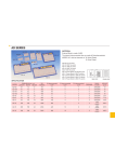
1
TINALab II Specification
SYNTHESIZED FUNCTION GENERATOR
WAVEFORM OUTPUT
Amplitude
Nominal Impedance
Protection
±10V, ±5V (into 50 Ohm)
50 Ohm
Short circuit protection in range of
±15V
Square, Ramp, Triangle, DC, Arbitrary
50MHz
Waveform
Bandwidth
Frequency range
Sine
Square, Triangle
Arbitrary
Synch Output (indicates 0V crossing)
4MHz
500kHz
depends on waveform
5V CMOS level
D/A CONVERTER
Resolution
Update Rate
10 [12] bits (<0.1% of full scale),
monotonic
40 MSPS
WAVEFORM MEMORY
Type
Capacity
Fast static RAM
Min. 65,536 * 16bits
DIGITAL OUTPUTS
# of Lines
Connection
16
all 16 bits wired to a shrouded male
connector
8 least significant bits wired to 2mm
sockets
5V tolerant devices
(5V TTL/CMOS, 3.3V LVCMOS)
Short circuit protection in range of ±15V
Compatibility
Protection
1
ANALOG INPUTS
# of Channels
Input Configurations
Full Scale Input Range
Nominal Impedance
2
Single ended
±80V
1 MOhm / 25pF
A/D CONVERSION
Resolution
Sample Rate (non-repetitive signal)
Equivalent Sample Rate
(repetitive signal)
10 [12] bit (no missing codes)
20 MSPS/channel
4 GSPS/channel
SYSTEM CHARRACTERISTIC
Bandwidth (-3dB)
dc .. 50MHz DC-coupled
2Hz .. 50MHz AC-coupled
FRAME MEMORY / CHANNEL
Type
Capacity
Input mode
Fast static RAM
min. 65536 * 16 bit
Digitized analog and/or digital
VERTICAL MEASUREMENT RANGES
Scale Factor
5mV/div .. 20 V/div
Attenuation Factors
x1, x2, x5
HORIZONTAL MEASURE RANGES
Scale Factor
10 s/div .. 2us/div
Scale Factor (repetitive signal)
10 s/div .. 10ns/div
Attenuation Factors
x1, x2, x5
TRIGGER SOURCE
Analog
Digital
Channels A, B, external
16 * 8 bits trigger pattern
TRIGGER RESPONSE (WAVEFORM GENERATING)
Free Run
[Internal] trigger then go
Single
One waveform then stop
Continuous
One waveform then wait for a trigger
2
DIGITAL INPUT
# of Lines
Connection
16
all 16 bits wired to a shrouded male
connector
8 least significant bits wired to 2mm
sockets
3.3V CMOS/TTL,
5V CMOS/TTL
min. ±15V
Compatibility
Overvoltage Protection
MULTIMETER
A/D CONVERSION
Resolution
12 bit
AC VOLTAGE
Measurement Range
Range Factors
Input Impedance
Bandwidth
10mV .. 100V RMS
x1, x2, x5
10 MOhm
20kHz
DC VOLTAGE
Measurement Range
Range Factors
Input Impedance
10mV .. 100V
x1, x2, x5
10 MOhm
AC CURRENT
Measurement Range
Range Factors
1mA .. 1A RMS
x1, x2, x5
DC CURRENT
Measurement Range
Range Factors
1mA .. 1A
x1, x2, x5
RESISTANCE
Measurement Range
Range Factors
10Ohm .. 1MOhm
x1, x2, x5
3
INTERFACE
USB 1.1
RS-232
full speed
115200 baud, full-duplex, 8, N, 1
DC POWER SUPPLY
Fixed DC output
+5V
-5V
Variable DC output
+15V
-15V
0.4A
0.1A
0.1A
0.2A
EXTERNAL POWER SUPPLY
Type
Input
Output
switching, external
100 .. 240VAC, 47 .. 63Hz
+5V/3A, +15V/0.8A, -15V/0.8A
GENERAL
Weight
Color
Dimensions (W x H x D)
ca. 1kg
Light gray
291 x 75 x 199 mm
4
Panel elements of TINALab II
5
1. Power On LED
2. +15V programmable power supply output Attention! For the time
being, the supply delivers only fixed +15V.
3. +5V fixed power supply output
4. Digital ground
5. Analog ground
6. -5V fixed power supply output
7. -15V programmable power supply output Attention! For the time
being , the supply delivers only fixed -15V.
8. Ch A Input (2mm socket connector) This is the signal input for
channel A.
9. Ch A Input (BNC connector) This is the signal input for channel A.
The outer (ground) connection is galvanically connected to the
instrument ground and consequently to the safety earth contact of
the line/mains plug.
10. Ch B Input (2mm socket connector) This is the signal input for
channel B.
11. Ch B Input (BNC connector) This is the signal input for channel B.
The outer (ground) connection is galvanically connected to the
instrument ground and consequently to the safety earth contact of
the line/mains plug.
12. Ext Trg Input (2mm socket connector) This serves as external trigger
signal input, if external triggering is selected.
13. Ext Trg Input (BNC connector) The serves as external trigger signal
input, if external triggering is selected. The outer (ground) connection
is galvanically connected to the instrument ground and consequently
to the safety earth contact of the line/mains plug.
14. 50Ω Output (2mm socket connector) Short-circuit-protected signal
output of the function generator.
15. 50Ω Output (BNC connector) Short-circuit-protected signal output
of the function generator. The output impedance is 50Ω, and the
maximum output amplitude is 20Vpp (open circuit) or 10Vpp when
terminated with 50 Ω.
16. Digital Inputs (shrouded male connector) Signal inputs of the Logical
Analyzer. The inputs are protected against external DC voltages up to
max. ±15V.
17. Digital ground
18. Digital Outputs (shrouded male connector) Signal outputs of the
Digital Signal Generator. The outputs are protected against external
DC voltages up to max. ±15V.
19. Digital ground
20. Digital Outputs (2mm socket connector) Signal outputs of the Digital
Signal Generator. The outputs are protected against external DC
voltages up to max. ±15V.
6
21. Test Card (50 contact card edge) Slot for test cards. Test cards are
ready-to-use circuits for measurement experiments manufactured by
DesignSoft, Inc.
22. Digital Inputs (2mm socket connector) Signal inputs of the Logical
Analyzer. The inputs are protected against external DC voltages up to
max. ±15V.
23. V Ω (2mm socket connector) Input terminal to measure voltage and
resistance with the multimeter. Attention! This input does not
work unless a TINALab II Multimeter Card is installed.
24. COM (2mm socket connector) Common ground of the multimeter
measuring V, Ω, I. This ground is independent of all the other
ground connections of the instrument (Gnd, Agnd).
25. I (2mm socket connector) Input terminal to measure current with the
multimeter. Attention! This input does not work unless a
TINALab II Multimeter Card is installed.
26. Reset button
27. User Port (shrouded male connector) Reserved for further
development.
28. USB interface Attention! All terminals of the USB interface are
galvanically connected with the instrument and subsequently
with protective (safety) earth potential.
29. RS-232 serial interface Attention! All terminals of the RS-232
interface are galvanically connected with the instrument and
subsequently with protective (safety) earth potential.
30. Power source connector
7
Accessories supplied
1.
2.
3.
4.
5.
6.
TINALab II Install CD (TINALab Basic)
TINALab II User Manual
External Power Supply (Fortron/Source, Model No: FSA30P32-S)
AC Power Cord (optional)
USB A-B Cable, 1.8m
RS-232 Cable, 2m (optional)
The cable contains 4 screened lines connected 1:1. TINALab II RS232 connection (9 pole D SUB female) is determined as follows:
Pin
1
3
5
7
8
Description
TXD (data from TINALab II to PC)
RXD (data from PC to TINALab II)
Ground (reference potential - connected via the power cord
with protective earth)
CTS (clear to send)
RTS (request to send)
7. 2 Oscilloscope Probe Kits (K&H, LF-101)
8. BNC Test Lead (K&H, LF-56)
9. Breadboard (K&H, RH-21)
10. Test Leads, 15cm, Standard color (K&H, KLG-0.65-2)
11. Test Leads, 30cm, Standard color (K&H, KLG-0.65-2)
12. Small wire set, 14 length/each 5pcs (K&H, SWS-03)
13. Test kit
200Ohm, 0.6W, Metal film, 1%
10nF, 400V, Foil capacitor, 10%
8.2mH, 0.1A, Inductor coil, 10%
Note: Subject to change without notice
8
TINALab II Specification
REV. E
DesignSoft Inc.
www.designsoftware.com
9