1
US006960190B2
(12) United States Patent
(10) Patent N0.:
(45) Date of Patent:
Stinson
(54) VACUUM REGULATOR AND METHOD
US 6,960,190 B2
Nov. 1, 2005
Brenda Shelton, et al, Medical Applications of Suction—A
Nursing Manual, 1985—Puritan Bennett Corporation.
(75) Inventor:
David C Stinson, Richmond Hill, CA
(Us)
(73) Assignee: AmveX Corporation, Richmond Hill
(CA)
(*)
Notice:
Subject to any disclaimer, the term of this
patent is extended or adjusted under 35
PA.
U.S.C. 154(b) by 0 days.
Boehringer Suction Regulators Operating and Maintenance
Instructions, 1992 NorristoWn, PA.
Boehringer Suction Regulators Information Brochure, 1998
NorristoWn, PA.
(21) Appl. N0.: 10/248,094
(22) Filed:
Dec. 18, 2002
(65)
* cited by examiner
Prior Publication Data
US 2004/0122365 A1
Vacutron Suction Regulator, Operations and Maintenance
Guide, Mar. 1989, Allied Healthcare Products, Inc., St.
Louis, MO.
Allied Healthcare Products, Inc., Instruments of Care.
Medical Gas Technology product brochure May 2002.
Ohmeda Product Information, Madison, WI.
Precision Medical User Manual, Nov. 1999, Northampton,
Primary Examiner—Nicholas D. Lucchesi
Jun. 24, 2004
Assistant Examiner—MattheW F. DeSanto
(51)
Int. Cl.7 .............................................. .. A61M 1/00
(52)
US. Cl. .................................................... ..
(58)
Field of Search ............................ .. 604/28, 30—31,
604/119
604/35, 500, 503, 505, 506,514, 65—67,
604/118—121, 245—247, 317—326; 128/205.19,
(74) Attorney, Agent, or Firm—EdWard W. Goebel, Jr.; Jon
L. Woodard; MacDonald Illig Jones & Britton
(57)
ABSTRACT
128/911
A vacuum pressure regulator system for use in association
(56)
References Cited
With a vacuum system in Which a vacuum is employed for
healthcare purposes, for assisting in monitoring and regu
U.S. PATENT DOCUMENTS
4,710,165 A *
12/1987 McNeil et a1. .............. .. 604/67
lating the vacuum pressure, and having a manual pressure
control valve to adjust the treatment vacuum pressure sup
4,795,448 A
1/1989 Stacey et 211.
plied to the patient, a vacuum pressure sensor to sense the
4,988,336 A *
1/1991
5,419,768 A *
5/1995 Kayser ..................... .. 604/119
treatment vacuum pressure for the patient in the system, and
producing a treatment vacuum pressure signal, a sampling
5,766,155 A
6,162,194 A *
2001/0035051 A1*
2003/ 0040687 A1
Kohn ........................ .. 604/67
6/1998 Hyman et 211.
12/2000 Shipp ....................... .. 604/151
11/2001 Karlicek .................... .. 73/708
2/2003 Boynton et a1.
circuit Which intermittently samples the pressure signal
generated by the pressure sensor and generate sampling
signals, an electrically poWered pressure display circuit, and
digital pressure display, for receiving the sampling signals
OTHER PUBLICATIONS
and providing a visible display, and, a non-mains poWer
supply.
AmveX Corporation Brochure.
Patricia L. Carroll, R.N., (MiddletoWn, CT) The Principles
of Vacuum & Its Use in the Hospital Environment.
8 Claims, 4 Drawing Sheets
/
VACUUM
SOURCE
46
32
22
u
“
com ROL
VE
MODE
,,
SELECTOR
r
as’)
CONTROL
I
KN ‘7B
PATIENT
44
PRESSURE
SAMPLER
AND DISPLAY
POTENTIOMETER l
48
U.S. Patent
Nov. 1,2005
Sheet 1 0f 4
US 6,960,190 B2
U.S. Patent
Nov. 1,2005
m !‘
mm
Sheet 2 0f 4
on
US 6,960,190 B2
US 6,960,190 B2
1
2
VACUUM REGULATOR AND METHOD
There is a need for a vacuum pressure regulator having a
The invention relates to medical and hospital healthcare
more precise pressure readout, preferably one that provides
a better visual readout, such as could be provided by a digital
numeral LCD display.
Preferably such a system Will be independent of mains
vacuum systems and in particular to a vacuum pressure
poWer, and Will be a system that is solid state operated, With
gauge and regulator having a solid state, non-mains poWered
battery poWer, for most applications, thus permitting it to be
sensor for monitoring the vacuum pressure and enabling the
used anyWhere in a facility or in the ?eld if needed.
BACKGROUND OF INVENTION
operator to maintain a stable level of vacuum for adminis
tration to a patient, and to a vacuum regulator incorporating
Preferably the vacuum pressure display Will be incorporated
10
such a vacuum pressure gauge.
In the ?eld of health care, vacuum systems are required in
many circumstances. A vacuum may be required to be
applied to a patient for a variety of reasons.
15
In these cases care must be taken to ensure that the level
attendant if there is a loss of vacuum.
Preferably the pressure regulator Will be designed to
of vacuum negative pressure is maintained at the level
required for a particular treatment. To do this manual con
trols, knoWn as vacuum regulators, are provided by Which
the level of vacuum pressure can be controlled and varied.
operate on a minimum of poWer, so that it can be poWered
by a long life battery, a rechargeable battery, a 12 volt
battery, or by solar poWer if desired. Mains poWer connec
tions could also be incorporated, so as to be available to be
Pressure gauges are also provided either incorporated in
used, When required, as an optional alternative supply.
The regulator control Will preferably incorporate a poten
or matched With the vacuum regulator Which monitor the
level of vacuum pressure.
In the past the mechanical systems in such vacuum
in the body of a manual vacuum pressure regulator, so that
the digital vacuum pressure display is provided in a single
compact unit.
Preferably there Will also be an alarm, of some form,
incorporated in the pressure gauge Which Will alert the
25
regulators for actually varying and controlling the vacuum
used simple vent valves and the like. Such valves could be
controlled manually usually by a control knob. The pressure
gauge Was usually a mechanical type gauge, Which consisted
tiometer connected to the logic so that When the control knob
is rotated to adjust the pressure, the sampling rate is
increased temporarily. This Will give an instantaneous read
out, on the display of the neW pressure.
SUMMARY OF INVENTION
of a pressure sensor With a dial, and a needle shoWing the
pressure. An operator Would glance at the dial and needle
With a vieW to providing the foregoing advantages, the
invention comprises a vacuum pressure regulator system for
from time to time to ensure that the vacuum level remained
stable at the desired pressure.
use in association With a vacuum system in Which a vacuum
Such knoWn pressure gauge systems have been someWhat
primitive.
35
is employed for healthcare purposes, for assisting in moni
toring and regulating the vacuum pressure, and Which
Usually knoWn vacuum regulators used a simple
mechanical type pressure gauge With a needle type readout
vacuum pressure regulator system has a manual pressure
dial shoWing the pressure. An operator Would monitor the
gauge reading and might adjust the manual pressure control
vacuum pressure supplied to the patient, a vacuum pressure
as desired. This system Was someWhat old fashioned for the
control valve operable by an operator to adjust the treatment
sensor operable to sense the treatment vacuum pressure for
40
the patient in the system, and to produce a treatment vacuum
pressure signal, a sampling circuit operable intermittently by
electrical poWer to sample said pressure signal generated by
hospital environment, and Was not alWays practical in emer
gency situations, for example in a paramedic environment,
at an accident scene for example, or in an ambulance. For
said pressure sensor at predetermined time intervals and
example, the dial and needle may require to be checked
repeatedly, and it Was possible for the paramedic to misread
the dial.
Such knoWn systems Were also capable of providing for
intermittent vacuum pulses to be supplied at intervals.
generate sampling signals, an electrically poWered pressure
display circuit, and digital pressure display, for receiving
said sampling signals and generating a visible digital pres
45
sure display, and, a non-mains poWer supply connected for
supplying poWer both to said sampling circuit for sampling
said vacuum sensor, and to said display circuit and said
The intermittent control in many cases was difficult to
digital display.
maintain and difficult to regulate as to timing.
The invention further seeks to provide such a vacuum
US. Pat. No. 4,988,336 issued Jan. 29, 1991, G. S. Kohn,
pressure regulator including a no-pressure signal generator
discloses a complex vacuum pressure regulator in Which the
for generating at least one no-pressure signal representing an
vacuum source is used to drive a rotary air poWered motor
Which in turn drives an electrical generator, Which is part of
absence of treatment vacuum pressure, and an alarm signal
55
the regulator. The vacuum control valve is electrically
generator, and an alarm responsive thereto, operable in
operated and turns the vacuum on and off for intermittent
supply of vacuum to the patient. This system is unnecessar
response to a no-pressure signal to generate an alarm.
The invention further provides such a vacuum pressure
ily complex in that it incorporates its oWn electrical genera
regulator system in Which said regulator is manually oper
tor, and uses that generator to poWer the electronic on/off
sWitching of the vacuum.
able to adjust said treatment vacuum pressure so as to
maintain a desired level of vacuum pressure.
US. Pat. No. 5,419,768 issued May 30, 1995, J. P. Kayser
The invention further provides such a vacuum pressure
discloses a vacuum regulator in Which the actual vacuum
gauge system in Which said no-pressure signal generator
control valve is operated by a solenoid. The solenoid is
programmed to open and close the valve automatically for
intermittent operation. This system is also complex, and
Would consume a considerable poWer supply.
65
responds to the occlusion of a treatment device connected to
a patient and signals an alarm.
The invention further provides such a vacuum pressure
regulator system in Which an operator override control is
US 6,960,190 B2
3
4
provided whereby an operator can manually override said
alarm (36). The alarm may be a ?ashing light, or an audible
buZZer or a combination of Warning alert devices.
pressure control valve and supply full vacuum for treatment
of said patient.
The vacuum applied to the patient may be and usually is,
A mode select sWitch (38) is operable to select either
automatic regulation or manual override, as desired.
In accordance With the invention a poWer source, in this
connected to the patient through a knoW collection bottle,
and material removed from the patient may be alloWed to
case a battery (40) is located Within housing (12) and is
collect in such a collection bottle thus preventing the mate
rial from being WithdraWn up into the vacuum system itself.
connected to a circuit board of the vacuum sensor as Will be
The invention also provides a method of supplying and
regulating a vacuum to a patient, With a non-mains poWered
10
regulator, and sampling the vacuum pressure at timed inter
supply and transformer.
vals so as to conserve poWer.
FIG. 4 illustrates the vacuum conduit connections Within
The various features of novelty Which characteriZe the
invention are pointed out With more particularity in the
claims annexed to and forming a part of this disclosure. For
the housing (12) betWeen the various mechanical compo
nents, corresponding to FIG. 3, but in schematic form.
15
a better understanding of the invention, its operating advan
tages and speci?c objects attained by its use, reference
should be made to the accompanying draWings and descrip
atmosphere (42) for alloWing entry of air to reduce the
vacuum pressure With the system. Such control valves are
tive matter in Which there are illustrated and described
knoWn, and the details are not shoWn for the sake of clarity.
The control knob (30) connects to the control valve for
manual operation and adjustment of the control valve by an
BRIEF DESCRIPTION OF DRAWINGS
operator. This permits the operator to manually adjust the
level of vacuum being supplied to the patient.
The mode selection control (38) alloWs an operator to
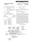
FIG. 1 is a schematic vieW of a vacuum pressure system,
25
invention;
select either an off position or an automatic operation
position, of the control valve, or manual override position,
FIG. 2 is a sectional illustration of a vacuum pressure
Which cuts out the control valve and applies full vacuum to
regulator of FIG. 1 along line 2—2 of FIG. 1;
FIG. 3 is a conduit diagram illustrating the layout of the
various conduits connecting the components of the pressure
regulator of FIG. 1;
FIG. 4 is a block diagram illustrating the connection of the
the patient.
A pressure sensor (44) senses the vacuum pressure and
mechanical components of the vacuum pressure controls
FIG. 1; and,
FIG. 5 is a block circuit diagram of the vacuum pressure
sensor and display.
The vacuum source (14) is shoWn connected to the control
valve (32). The valve (32) is connected to a vent, to
preferred embodiments of the invention.
shoWing the vacuum pressure regulator illustrating the
described beloW. Other forms of poWer source could replace
the battery or could be combined With the battery, a
rechargeable storage device, solar poWer, or a mains poWer
35
DETAILED DESCRIPTION
provides a pressure signal.
FIG. 5 illustrates the electronic circuit by Which the
pressure signal is sampled at intervals. Afurther vent (46) is
provided in the line connection to the patient. A sampler
circuit (48) is located in housing (12), Which is described
beloW.
A pressure sampler (50) is connected to the pressure
sensor (44), and operates at intervals to sample the pressure
detected in the pressure sensor. Sampler (50) is poWered by
Referring to FIG. 1 it Will be seen that the invention is
there illustrated in the form of a vacuum regulator (10)
having a housing (12), a vacuum source connection (14),
and a vacuum patient connection (16). Typically the vacuum
connection (14) Will be connected to a knoWn vacuum
40
conduit (18) common in many hospitals, and paramedical
45
poWer supply (40). This can be anyone of, or a combination
of the various different poWer supplies listed above.
Pressure sampler (50) is connected to ampli?er (52) to
amplify the pressure signal.
Ampli?er (52) is connected to micro controller (54).
vehicles. The conduit, in a hospital is located in or on a Wall,
Controller (54) is connected to a digital display, typically an
LCD display, shoWn as (56). Display (56) is located in
and has connection points in various rooms, by means of
WindoW 44 above. The controller (54) is also connected to
Which a paramedic, doctor or nurse, may have quick access
to a source of vacuum Wherever required. The patient
the potentiometer of control knob (30). The controller (54)
controls the sampler (50) Which then samples the pressure at
connection (16) may be connected by a patient hose (20) to
predetermined time intervals. This provides a read out on the
a vacuum tube or device (not shoWn), by means of Which the
patient may be treated With a vacuum in any desired cir
reduces the poWer consumption of the system. Thus, a poWer
cumstances.
supply in the form of a long-life battery Will provide
display (56) each time a sample is taken. This greatly
Typically a collector bottle (24) is provided in the patient
hose, for collecting any mucous or other material removed
from the patient via the hose.
Referring to FIGS. 2 and 3 the components Within the
vacuum regulator housing are seen in more detail. On the
housing (12) there is a manually operable control knob (30)
connected to a pressure control valve (32) Within housing
(12). By operation of knob (30) the vacuum pressure can be
adjusted, manually, as desired. Knob (30) is coupled With a
control sensor, in this case a potentiometer ring (31) knoWn
per se (FIG. 4), for reasons described beloW.
55
eXtended operation, Without the need for a mains connec
tion.
The sampling rate can be changed by the controller (54).
Thus, as the control knob (30) is rotated, the controller (54)
Will temporarily increase the sampling rate of the sampler
(50). In this Way the display Will give an instantaneous
reading of the neW pressure setting.
A memory (58) is connected to controller (54).
The foregoing is a description of a preferred embodiment
of the invention Which is given here by Way of eXample only.
The invention is not to be taken as limited to any of the
The vacuum regulator (10) has a visual indicator or 65 speci?c features as described, but comprehends all such
variations thereof as come Within the scope of the appended
WindoW (34) for a display (described beloW), on Which the
claims.
treatment vacuum pressure is displayed, and also has an
US 6,960,190 B2
6
5
What is claimed is:
3 and including sensing an absence of vacuum pressure and
generating an alarm signal thereby.
1. The method of regulating a vacuum treatment to a
patient supplied from a vacuum sources by means of a
5. The method of regulating a vacuum treatment to a
patient supplied from a vacuum source as claimed in claim
non-mains powered vacuum regulator and comprising:
sensing the pressure of vacuum being supplied to the
4 and including operating an override sWitch Whereby to
override said venting of said vacuum pressure, and to supply
full vacuum pressure to said patient.
6. A method of regulating the level of vacuum adminis
tered to a patient comprising:
patient, at regular time intervals, so as to conserve
poWer, and generating pressure signals thereby;
supplying said pressure signals to a display, Whereby the
pressure of said vacuum can be monitored;
manually operating a control valve to control said vacuum
pressure; and
10
administered to said patient;
(b) intermittently sensing said vacuum With circuitry to
sensing a change in the position of said manual control,
and generating a control signal thereby and said control
signal varying said intervals of said intermittent pres
general signals in response thereto;
(c) supplying said generated signals to a display to
digitally display said level of vacuum;
sure sensing, Whereby to provide an instantaneous
(d) poWering said circuitry by a battery;
(e) amplifying said intermittently sensed vacuum;
display of pressure.
2. A method as claimed in claim 1 including providing
circuitry poWered by a mains poWer supply With a trans
former.
(f) including a micro controller in the circuitry for gen
erating said signals to said display;
(g) reducing poWer requirements from said battery When
3. The method of regulating a vacuum treatment to a
patient supplied from a vacuum source by means of a
non-mains poWered vacuum regulator and comprising:
sensing the pressure of vacuum being supplied to the
patient, at regular time intervals, and generating pres
sure signals thereby;
supplying said pressure signals to a display, Whereby the
(a) adjusting a pressure control valve to a selected vacuum
said
micro processor intermittently
senses said
vacuum;
(h) generating an alarm When said microprocessor senses
an absence of vacuum;
25
pressure of said vacuum can be monitored;
manually operating a control valve to control said vacuum
pressure; and
sensing a change in the position of said manual control,
and generating a control signal thereby and said control
signal varying said intervals of said intermittent pres
(i) manually adjusting said pressure control valve;
intermittently sensing said vacuum at a pre-selected
time interval; and
(k) temporarily increasing said time interval When manu
ally adjusting said pressure control valve.
7. A method as claimed in claim 6 including the step of
manually overriding said pressure control valve to supply
sure sensing, Whereby to provide an instantaneous
full vacuum to said patient.
8. A method as claimed in claim 7 including saving said
display of pressure.
generated signals in memory.
4. The method of regulating a vacuum treatment to a 35
patient supplied from a vacuum source as claimed in claim
*
*
*
*
*