1
ADVANCED AND EVER ADVANCING
Mitsubishi Programmable Logic Controller
DATA BOOK
ELECTRIC CORPORATION
HEAD OFFICE : MITSUBISHI DENKI BLDG MARUNOUCHI TOKYO 100-8310 TELEX : J24532 CABLE MELCO TOKYO
NAGOYA WORKS : 1-14 , YADA-MINAMI 5 , HIGASHI-KU, NAGOYA , JAPAN
When exported from Japan, this manual does not require application to the
Ministry of International Trade and Industry for service transaction permission.
Specifications subject to change without notice.
Printed in Japan on recycled paper.
MITSUBISHI ELECTRIC
Opening up new possibilities for Factory Automation
with more compact, faster and easier to use PLCs.
The assets accumulated for the A and QnA series
can be utilized effectively for the Q series.
Windows, Microsoft Excel, Visual Basic and Visual C++ are either trademarks or registered trademarks of Microsoft Corporation in the
United States. Other product and company names herein may be either trademarks or registered trademarks of their respective owners.
48454
Features
SPACE EFFICIENT
Having about 60% of the conventional AnS series mounting area, the
ultracompact Q series contributes to equipment space saving.......Refer to P. 1-1.
OPTIMIZED CONFIGURATION
Program capacity Max. 252k steps, 8192 points of I/O control,allowing
optimal configuration of small to large scale systems.......Refer to P. 1-3.
Q mode
HIGH PERFORMANCE
1ms processing of 12k steps opens up possibilities for high
performance and precision control.................................................Refer to P. 1-2.
Improved debugging
A wide variety of functions designed for program design and
debugging efficiency...............................................................................Refer to P. 1-8.
A mode
USER FRIENDLY
Development and maintenance efficiency is improved with a user-friendly,
comfortable Windows comprehensive environment.......Refer to P. 1-7.
PC-related
INFORMATION CONSOLIDATION
Easy network configuration and high-performance networking in
response to computerization of production facilities.......Refer to P. 1-5.
RELIABILITY
GOT-A900
Reliable products and easy troubleshooting functions for
decreased downtime...............................................................................Refer to P. 1-4.
UTILIZATION
Ease of developing Q programs using the existing A/QnA programs. Use of the
A mode facilitates enhanced performance of the AnS system.......Refer to P. 1-9.
The Q series is available in two different modes of operation: the Q mode which uses the Q series' inherent functions and
performance capabilities; and the A mode which uses the conventional AnS series' programs and hardware and is
significantly enhanced in CPU processing capabilities. (Refer to P. 1-9.)
Unless otherwise specified, this data book introduces the Q mode features, which applicable may not be for A mode use.
Appendices
FEATURES
SPACE SAVING AND WIRING SAVING
To save machinery and equipment space and to reduce costs by
decreased wiring processes, the Q series is smaller in its mounting
area and has higher freedom of installation. It also has increased
affinity with CC-Link, for easier use.
Mounting Area
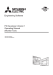
The mounting area of the Q series is 60% smaller than that of the conventional compact model (AnS series).
Mounting area comparison
Q25HCPU
QX10
QX10
QX10
QX10
QX41
QX41
QX41
POWER
MODE
RUN
ERR
USER
BAT
BOOT
98mm
(3.86inch)
PULL
USB
RS-232
QX41
QJ71BR11
RUN
T.PASS
SD
ERR
0
1
2
3
4
5
6
7
8
9
A
B
C
D
E
F
0
1
2
3
4
5
6
7
8
9
A
B
C
D
E
F
0
1
2
3
4
5
6
7
8
9
A
B
C
D
E
F
QJ71BR11
MNG
D.LINK
RD
L ERR
RUN
T.PASS
SD
ERR
QJ71BR11
MNG
D.LINK
RD
L ERR
RUN
T.PASS
SD
ERR
QJ71BR11
MNG
D.LINK
RD
L ERR
RUN
T.PASS
SD
ERR
MNG
D.LINK
RD
L ERR
0
1
2
3
4
5
6
7
8
9
A
B
C
D
E
F
(Depth: 98mm(3.86inch))
5-slot main base 245mm(9.65inch)
8-slot main base 328mm(12.92inch)
12-slot main base 439mm(17.30inch)
(Main and extension bases are the same size)
Mounting Freedom
CC-Link
The Q series has a wide assortment of 5-, 8- and 12-slot
bases. The freedom of mounting space allows reduction in the
number of required bases.
AnS
series
Q
series
Base unit types
Number of I/O Slots
5
8
12
Main Base
Q35B
Q38B
Q312B
Extension Base
Q65B
Q68B
Q612B
Mounting Size (mm(inch))
245(9.65)X98(3.86)
328(12.92)X98(3.86)
439(17.30)X98(3.86)
Note 1: The base units are designed for the Q series I/O, intelligent
function and network modules. The AnS series modules cannot
be loaded on the base units given in the above table.
1-1
The Q series has increased affinity with CC-Link, for easier
use. Using the GPPW network setting screen, you can set the
network parameters and the automatic refresh of the remote
I/O signals to the CPU internal memory. In addition, you can
make automatic setting of initial setting data to remote device
stations, such as the analog-to-digital converter and highspeed counter, so that you can carry out programming without
needing to be aware of the network.
FEATURES
Features
INCREASED PERFORMANCE AND ACCURACY OF FACILITIES
The Q series has significantly improved CPU operation processing speeds, e.g.
achieved a scan time of 0.5ms in programs of approx. 4k steps and 1ms in
programs of approx. 12k steps (Note 2). Also, with the addition of a cyclic
execution program run system and a program start interrupt function from
network/intelligent function module, the Q series has opened up possibilities for
shortened machinery/equipment tact time and increased machining accuracy.
Operation Processing Speeds
The Q series high-speed type CPU has realized speeds as high as 34ns for basic instruction processing time of and a PC MIX value of
10.3 (Note 3). It is about 5 times faster in performance than the conventional model A2USHCPU-S1 and about 2.7 times faster than the
Q2ASHCPU. In addition, it has dramatically increased floating-point operation speeds for PID and other arithmetic functions.
PC MIX values and LD instruction processing times
CPU operation processing speeds
10.3
Q25HCPU
3.8
Q2ASHCPU
Instruction
Q02CPU
LD
(LD X0)
OUT
(OUT Y0)
Timer (OUT T0 K5)
Transfer (MOV D0 D1)
Addition (+ D0 D1)
Floating-point addition (E+)
79ns
158ns
632ns
237ns
395ns
1815ns
4.4
2.0
A2USHCPU-S1
0
2
4
6
8
10
12
PC MIX value (instruction/ s)
34
Q25HCPU
75
Q2ASHCPU
90
A2USHCPU-S1
0
20
40
60
80
PC MIX value
Q02HCPU
Q06HCPU
Q12HCPU
Q25HCPU
34ns
68ns
272ns
102ns
170ns
782ns
10.3
100
LD instruction processing time (ns)
Also, the END instruction processing time has been reduced greatly by the use of a multi-processor configuration which is made up of
the control processor for program execution and the information processing processor for communication processing, etc.
Note 2: Scan time varies with the program contents and system configuration. The scan times given are values that can be achieved under given conditions.
Note 3: The PC MIX value is the average number of instructions such as the basic and data processing instructions executed in 1 s. A larger value indicates a higher processing speed.
Adoption of High-Speed System Bus
The Q series high-speed system bus is 4 to 8 times faster than
that of the conventional series, giving rapid I/O refresh and
network data refresh. (Refer to P. 9.)
Cyclic Execution Program
The DC input modules input response time can be changed.
The response time can be chosen from among 1, 5, 10, 20
and 70ms according to your application.
Event Interrupt
A cyclic execution program is started and run at predetermined time
intervals. High accuracy can be provided if you use this program in
the processing of areas which will particularly influence machining
accuracy. The cyclic time intervals can be set to 0.5ms-60s.
Ordinary scan execution program
Data
END
A CPU interrupt program can be started from a network or
intelligent function module. Using this function, fast response
can be made to an event which occurs asynchronously with
the program scan of the PLC, e.g. data receiving from a
network or count value match of high-speed counter.
Interrupt
0
Variable Time Constant of Input Module
Cyclic execution program
0.5ms
0.5ms
1-2
FEATURES
OPTIMUM SYSTEM CONFIGURATION
Production facility control grows more and more sophisticated. Also, it is
necessary to process large volumes of production data, e.g. more
precision production control, quality control, and recently, resources/energy
control in consideration of global environment. To meet such needs, the Q
series is designed to handle large volumes of programs and data.
Program Capacities
Extended Memory
The Q series has a wide assortment of CPU modules having
28k-, 60k-, 124k- and 252k-step program capacities, enabling
a selection of the CPU module which matches the
machinery/equipment control capacity.
Each CPU module is equipped with a small PC card slot to
accept extended memory of up to 32MB (when using the ATA
card). By loading large-capacity extended memory, you can
perform large-capacity file management, and comment
settings for all data devices and past programs can be stored
in memory as a correction history.
CPU program capacities (steps)
Q02CPU
Q02HCPU
28k
Q06HCPU
60k
Q12HCPU
124k
Q25HCPU
252k
All device comments
Memory card
Extended file registers
(when SRAM card/flash card is used)
Extended file registers
(when SRAM card/flash card is used)
Number of Control I/O Points and Number of I/O Modules
Program, year**, month**, day** version
The Q series can control a maximum of I/O. 4096 points (max.
8192 points when used with a remote I/O network such as
CC-Link)regardless of the CPU module type.
Program, year**, month**, day** version
Up to 7 Extension Bases Connectable
Up to seven extension bases (eight bases including the main)
can be connected to accept up to 64 modules. Also, the overall
distance of extension cables is max. 13.2m(43.28feet),
enabling high freedom of extension base layout.
se
n ba
Mai
Note 1: If a 12-slot base is used, the total number of I/O, intelligent
function and network modules is restricted to 64.
Max. 64
modules
th ex
Seven
1-3
tensio
n bas
e
Longest overall
distance of
13.2m(43.28feet)
FEATURES
Features
EASE OF MAINTENANCE
Needless to say, maintenance is essential to exhibit the inherent
performance of machinery and equipment. However, as business areas
increase and machinery and equipment are installed all over the world,
it will be important to smoothly carry out on-the-spot maintenance. The
Q series has functions to minimize this maintenance-related problem.
Remote Programming
The Q series-compatible GPPW function software
allows online programming and monitoring and testing
operations to be performed with the Q series PLCs
installed at remote locations. Connections to the Q
series PLCs connected to Ethernet can be made via
Ethernet and connections to the PLCs connected with
modems can be made
via telephone line/ISDN
line and modems.
Telephone line
Modem
Built-In ROM
To reduce the possibility of program data erasure due to
battery failure, built-in flash ROMs are included in all CPU
types so there is no need to add a memory card to store
programs onto ROM.
Modem
Output Modules Provided with Short-Circuit Protection
Some transistor output modules use transistors provided with
short-circuit protection to protect output modules from being
burnt out due to a wiring mistake or external device failure.
Intelligent Function Module Monitoring
System Monitoring
System monitoring gives you an at-a-glance error detection
condition of each module in a PLC system. It supports
restoration at occurrence of trouble.
You can confirm the operating status and error detection condition
of an intelligent function module (Note 2) on a monitor screen. In
addition, the intelligent function module is monitored via a CPU
module, eliminating the need for separate cable connection.
Note 2: An intelligent function module is a generic term for special modules other than
digital I/O such as analog-to-digital converter and high-speed counter.
Note 3: The utility package corresponding to the intelligent function module is needed.
1-4
FEATURES
COMPUTERIZATION
With the increase of demands for production control, quality control and
resources/energy control, to say nothing of control data, there is a demand for rapid
transmission of production information data between PLCs and between PLC and host
monitoring/controlling system. The Q series has increased network data transmission
speed and reinforced its tools to configure a network system more easily.
Communication Support Software Package
The communication support software package is a software tool for Windows
for easy connection of a host monitoring/controlling Windows personal
computer to the Q series (connection to QnA, A or FX series also possible).
You can easily create a monitoring/control application in Visual Basic, Visual
C++ or Excel, without being conscious of the different complicated
communication protocols of Ethernet, MELSECNET/10, CC-Link, RS-232
serial communication or CPU programming port (RS-232 or USB).
Utilization of the Internet
Automatic Notice from PLC
The Q series Ethernet module has an e-mail communication
function which utilizes the Internet. You can transfer production
control information to/from anywhere in the world and
configure a remote monitoring/control system easily.
Mail server
A serial communication module (RS-232/422) connected to a personal
computer has a function to automatically send data from the PLC to
the personal computer when a given condition holds. Also, on
Ethernet, this function can be used for e-mail transmission. Use of this
function permits rapid transmission of alarm occurrence information or
the like without waiting for polling from the personal computer.
Automatic notice of
alarm information
Q series PLC
Q series PLC
Mail address + attached file
GOT Connection
The GOT-A900 series graphic operation terminal can be
connected using a CPU RS-232 port or serial communication
module. By connection to
the Q series high-speed
bus, you can achieve a
much,
faster-response
graphic operation terminal.
1-5
Network Parameter Setting
In the Q series, the network parameter setting screens for
Ethernet, MELSECNET/10(H) and CC-Link are included in the
GPP function software. Ethernet, CC-Link or other network
setting which had to be made in sequence programs can be
made on the screen, reducing programs and improving
viewability of settings.
FEATURES
Features
COMPUTERIZATION
In the Q series, Ethernet, MELSECNET/10(H) and CC-Link are placed as
open networks having performance capabilities and functions required for
information network, controller network and field network, respectively, to
meet the needs requested for facility control and production control networks.
Seamless Communication
The Q series Ethernet, MELSECNET/10(H) and CC-Link allow communication in
which the differences in network type and network hierarchy are not perceivable. Data
can be transferred from any PLC to any PLC, and GPPW connected to the PLC can
monitor the program of any PLC. (Note 1)
Note 1: Accessible to a PLC on a network located
beyond max. 7 PLCs serving as gateways
connected to two networks.
Ethernet
MELSECNET/10H
MELSECNET/10H
CC-Link
Increased Communication Data Capacities
To respond to increasing information volumes, the Q series network has been
increased in the volume of data that can be read/written by one time of communication.
Number of link relays (LB)/link registers (LW) points per network
MELSECNET/10H
MELSECNET/10
16k points
each
8k points
each
The Q series MELSECNET/10H module has a choice
of two operation modes: the MELSECNET/10H mode
high in speed and large in capacity; and the
MELSECNET/10 mode which maintains compatibility
with the conventional A/QnA series.
Increased Data Communication Speed
The system bus has been increased in speed to shorten the total
transmission time if communication data capacity increases. The data
transfer speed between CPU module and network module is about 4 to
8 times higher than that of the conventional QnA series. This increased
speed can minimize the influence of large-capacity data communication
on the CPU scan time. However, communication speed of Ethernet,
MELSECNET/10H and CC-Link have not been changed to maintain
communication compatibility with the conventional series.
Number of word device points read/written by one time of
MELSEC communication protocol communication
960
points
Q series Ethernet
QnA series Ethernet
High-speed
bus
480
points
1-6
FEATURES
EASE OF PLC USE
Enhanced functions of PLCs tend to make them less user-friendly. The Q
series offers easier-to-use PLCs with Windows comprehensive environment.
Added-In Functions
Centering on the GPP function software, the Q series Windows
comprehensive environment allows various optional user-friendly
software programs to be added to GPPW.
Ladder logic test tool
GPP function software package
Added
Added
Added
Data setting/monitoring software for
various intelligent function modules
Data converting software
Batch Monitoring of CPU and Intelligent Function Modules
The Q series has utility packages available for intelligent function modules such as analog-to-digital conversion units. Using the utility
packages allows you to make function setting needed to use the functions of intelligent function modules on the screen, e.g. make analogto-digital conversion enable/disable setting and the automatic refresh setting of analog-to-digital conversion data to CPU internal memory
in an analog-to-digital converter module, thus removing the need for programs. Also, sequence programs and various intelligent function
modules can be monitored/tested at the same time to improve the debugging of programs related to the intelligent function modules.
Sequence
program
monitoring
Intelligent
function module
monitoring
1-7
FEATURES
Features
PROGRAM DEVELOPMENT/DEBUGGING EFFICIENCY IMPROVEMENT
Sophisticated machinery and equipment and increased program scale result in the increased number of
program development processes. The Q series has inherited and developed the program structuring and
standardizing techniques achieved by the QnA series, and has functions to suppress and further reduce the
increase in the number of program development processes. Also, debugging-related functional performance
has been improved to increase the debugging efficiency in the stage of adjusting machinery and equipment.
Program Structuring/Standardization
The Q series allows multiple programs made on a
machinery/equipment operating function basis to be created
and executed. The programs divided function-by-function can
increase program utilizability and viewability. The Q seriescompatible GPPW function software enables SFC
programming which is more suitable for structuring and
standardization, in addition to ladder and list programming.
Automatic operation program
Communication processing program
Manual operation program
Online Program Correction
During adjustment of machinery/equipment, partial correction to a
program may sometimes be made without stopping PLC processing.
The Q series enables online correction to a program (write during
RUN) and there are no restrictions on the corrected program
capacity. Online rewriting of a program file is also possible, exhibiting
the high performance of program correction during adjustment.
Creation of User-Defined Instructions
The Q series allows a given program block to be defined and registered as
a single instruction (macro instruction function). Definition/registration of an
frequently used program block as a macro instruction increases program
utilization efficiency. In addition, viewability is improved since the program
read from the PLC is displayed as-in the defined macro instruction format.
Increased Speeds of Programming Ports
Offline debugging (simulation)
The LLT (ladder logic test tool) is a personal computer
software tool designed to start a virtual PLC on a simulate PLC
operations and debug sequence programs. You can debug
programs on a personal computer right after designing, without
waiting for the completion of PLC I/O wiring.
The Q series CPU modules are standard-equipped with a RS-232
port operable at max. 115.2kbps and a 12Mbps USB port installed
in recent personal computers (Q02CPU is equipped with RS-232
only). These high-speed programming ports have achieved much
shorter program transfer time and faster monitoring, increasing the
efficiency of machinery/equipment adjustment.
26k-step program and parameter write time (s)
12
Q25HCPU(USB)
Q25HCPU(RS-232)
Virtual PLC in
personal computer
30
86
Q3ACPU
94
A4UCPU
0
Program
Monitoring/
debugging
10 20 30 40 50 60 70 80 90 100
Note: The time may be longer than above depending on the performance
of the personal computer and the conditions of communication with other devices.
Password Function
Programs and data within the Q series CPU module can be protected
by a password. This function is effective for prevention of program
damage due to accidental operation or copying of specifically
developed programming techniques included in the programs and data.
1-8
FEATURES
UTILIZATION OF EXISTING ASSETS (COMPATIBILITY MAINTAINED)
We offer the customers who already use the A/QnA series PLCs
with the means to utilize the assets of the A/QnA series and use the
excellent functions and performance capabilities of the Q series.
Mode Selection
The Q series CPU is available in two different CPUs: one for Q mode and the other for A mode. Use the Q mode CPU to make the most of the performance capabilities and
functions of the Q series, or the A mode CPU to use the hardware configuration of the conventional AnS series as-is and improve the performance of the CPU only.
Q Mode
Designed to make the most of the inherent functions and
performance capabilities of the Q series by combining the Q series
CPU and other Q series modules. If the appropriate module is not
available from the Q series, you can use the AnS series module.
Features
CPU type
Usable programs
Q02CPU, Q02HCPU, Q06HCPU, Q12HCPU, Q25HCPU
Q series programs
Usable functions
Various functions introduced in this data book are all usable.
Usable base units
For Q series modules: Q3 B, Q6 B, for A series modules: QA1S6 B
Usable power supply modules For Q series modules: Q6 P-A1/A2, for A series modules: A1S6 P
Usable I/O, special,
For Q series and AnS series (Note 1)
network and other modules
A900GOT. Connection method: CPU RS-232, serial
Usable GOT
communication module, MELSECNET/10, CC-Link, bus
A Mode
Designed for the customer who is using the AnS series to improve only the
processing performance of the CPU without changing its programs and
hardware. Among the current AnS series hardware, you only need to change the
CPU module, bases and extension cables to increase the processing speed.
Q02CPU-A, Q02HCPU-A, Q06HCPU-A
A series programs
Only the functions usable in the A series can be used, and various functions
introduced in this data book are not usable with the exception of some functions.
QA1S3 B, QA1S6
A1S6 P
For AnS series
A800/900GOT. Connection method: CPU RS-232, computer link
module, MELSECNET/II/10/B, CC-Link (bus not connectable)
For Q series
Usable peripheral devices
Main base
Q3 B is used
B
For A series
Main base of
A mode CPU Power supply, I/O, special and
QA1S3 B is used
network modules are all for Ans
Q mode CPU and Q series modules
Extension cable
for Q series is
used
System configuration example
Extension cable
for Q series is used
As required, AnS power supply, I/O special and
network modules may be used in extension
base. Use QA1S6 B with AnS modules. As a
matter of course, Q series modules can be
added. Use Q6 B with Q series modules.
Q series-compatible software
is used on Windows personal
computer. (SW4D5C-GPPWE or later is usable.) Use
QC30R2 cable.
Extension base
A series-compatible software is used on Windows personal
of QA1S6 B is used computer, or A6GPP, A8PUJ or similar A series peripheral
device may be used. Note that since peripheral port of A mode
CPU is RS-232, RS-232/422 conversion cable is needed for use
of A series-compatible device of RS-422 specifications. (Note 4)
Note 1: Some modules for the AnS series, e.g. MELSECNET/II and MELSECNET/B, are not usable or have operating restrictions.
When Using Q Mode CPU
When Using A Mode CPU
The Q mode CPU requires Q series (Q mode) programs. As a conversion
tool is available to convert A/QnA series programs into Q series (Q mode)
programs, transition to the Q series can be made easily without wasting
your program assets. (Note 2)
Note 2: Conversion into Q series programs is needed
when you use the Q mode which makes the most of
the Q series CPU functions. A series programs can
be used as-is when you use the A mode.
FX series
program
1-9
A series
program
Using the A mode CPU in the your current system,
you can enhance the CPU performance easily.
Q02HCPU-A
5.6
2.0
A2USHCPU-S1
Q series
program
0
1
2
2.8 times
3
4
5
PC MIX value
QnA series
program
Note 4: The RS-232/422 conversion cable FA-CNV2402CBL
(0.2m(0.66feet)) or FA-CNV2405CBL (0.5m(1.64feet)) is
available from Mitsubishi Electric Engineering Co., Ltd.
2. Q MODE
1. OVERVIEW
CONTENTS
• Utility Package for Serial Communication Modules:
• Overview of Q Mode ...................................................2-1
SW0D5C-QSCU-E.................................................... 2-83
• Comparison between Q Mode and A Mode ................2-2
• I/O Modules............................................................... 2-85
• Compatibility of Q Mode PLC with AnS/Q2AS ............2-3
• Input Modules ........................................................... 2-87
2. MODEL SELECTION
• Output Modules......................................................... 2-93
• General Specifications ................................................2-4
• Applicable Model List ..................................................2-5
• Q Mode CPU Modules: Q02CPU, Q02HCPU,
• CPU Built-in Memories/Memory Cards......................2-24
• Network Overview .....................................................2-27
• Ethernet: QJ71E71, QJ71E71-B2 .............................2-36
• MELSECNET/10H: QJ71LP21, QJ71BR11 ..............2-43
• MELSECNET/10H: A6BR10, A6BR10-DC................2-53
• CC-Link: QJ61BT11 ..................................................2-55
• MELSECNET/MINI-S3: A1SJ71PT32-S3, A1SJ71T32S3..............................................................................2-66
• MELSEC-I/O LINK: A1SJ51T64................................2-68
• B/NET: A1SJ71B62-S3 .............................................2-69
• JPCN-1 Field Network: A1SJ71J92-S3, A1SJ72J95
..................................................................................2-70
• S-LINK: A1SJ71SL92................................................2-71
• Profibus-FMS/Profibus-DP interface: A1SJ71PB96F
/A1SJ71PB92D .........................................................2-72
• DeviceNet: A1SJ71DN91 ..........................................2-73
• Modbus interface: A1SJ71UC24-R2-S2/
A1SJ71UC24-R4-S2 .................................................2-74
Q68ADV, Q68ADI ................................................... 2-100
• Utility Package for Analog-to-Digital Conversion
Modules: SW0D5C-QADU-E .................................. 2-103
• Digital-to-Analog Conversion Modules: Q62DA, Q64DA
................................................................................ 2-104
• Utility Package for Digital-to-Analog Conversion
Modules: SW0D5C-QDAU-E .................................. 2-107
• High-Speed Counter Modules: QD62, QD62E, QD62D
................................................................................ 2-108
• Utility Package for High-Speed Counter Modules:
SW0D5C-QCTU-E .................................................. 2-114
• Positioning Module: QD75P1, QD75P2, QD75P4,
QD75D1, QD75D2, QD75D4 .................................. 2-115
• Positioning Module Software: SW0D5C-QD75P-E . 2-123
• Current Consumption Calculation ........................... 2-125
• Power Supply Modules: Q61P-A1, Q61P-A2, A1S61PN,
A1S62PN, A1S63P ................................................. 2-126
• Base Units: Q3
B, Q6
B, QA1S6
B............ 2-129
• Accessories: Batteries, Cables, Connectors ........... 2-130
• External Dimensions ............................................... 2-136
3. PROGRAMMING
• Intelligent Communication: A1SD51S .......................2-75
• Sequence Programs ............................................... 2-138
• ID Interface: A1SJ71ID1-R4, A1SJ71ID2-R4,
• Network Setting: SW5D5C-GPPW-E ...................... 2-159
A1SD32ID1, A1SD32ID2 ..........................................2-76
• Serial Communication Modules: QJ71C24,
QJ71C24-R2 .............................................................2-77
• Data Conversion Software: SW0D5C-CNVW-E...... 2-160
• Peripheral Devices.................................................. 2-161
4. SIMULATION/DEBUGGING FUNCTIONS
• Sequence Program Simulation ............................... 2-162
Overview of Q Mode
The Q series CPU modules are available in either Q mode and A mode products, which offers a wide selection of products
for different purposes.
The Q series has been developed to be higher in performance and easier to use while simultaneously having the heritage
of MELSEC's programming capabilities, network capabilities, various functions and operation procedures. The Q mode is
designed to exhibit the inherent functions and performance capabilities of the Q series. It can improve functions and
performance capabilities in the whole PLC system including not only the CPU but also the I/O and network modules and
various intelligent function modules.
The A mode is designed to merely improve the performance capabilities of the CPU for users with AnS PLC. With the A
mode, only the CPU modules, base units and extension base cables need to be changed in a current AnS series system.
The other modules and programs can be used as they are, the new CPU brings about an increase in the CPU processing
speed and program capacity.
2-1
Q mode
Q06HCPU, Q12HCPU, Q25HCPU ...........................2-15
• Analog-to-Digital Conversion Modules: Q64AD,
1
OVERVIEW
Comparison between Q Mode and A Mode
Comparison between Q Mode and A Mode
Q Mode
CPU type
Q02CPU, Q02HCPU,Q06HCPU, Q12HCPU,Q25HCPU
Available functions, modules, etc.
Program
Inherits the basic programming and instruction representing
methods of MELSEC. However, because of different internal
codes, A/AnS/QnA/Q2AS programs must be used after
conversion into Q mode.
Function
Functions given in the "Features" Chapter of this data book
are usable.
I/O, special modules
Base unit
Extension cable
Power supply module
Connectable networks
Ethernet
MELSECNET/10H
(Inter-PC network)
MELSECNET/10
(Inter-PC network)
MELSECNET/10
(Remote I/O network)
MELSECNET/II
MELSECNET/B
CC-Link
MELSECNET/MINI-S3
RS-232/422/485
Other networks
For Q series and AnS series
A6SIM-X64Y64 cannot be used.
B
For loading Q series modules: Q3
B, Q6
For loading AnS series modules: QA1S6
B
QC
B
For loading into Q series base unit: Q6
P-A1/A2
For loading into AnS series base unit: A1S6
P
Basically, there are only functions that are usable with the
AnS series though some specifications have been expanded
in performance. For expanded specifications, refer to the
Chapter for the A mode.
For AnS series
A6SIM-X64Y64 cannot be used.
B, QA1S6
B
For loading AnS series modules: QA1S3
QC
B
P
A1S6
Allowed
Disallowed
Allowed
Allowed
Disallowed
Allowed
Disallowed
Allowed
Allowed (with automatic refresh parameter setting)
Allowed (without automatic refresh parameter setting)
Allowed
Same as the networks compatible with AnS series
Allowed (without automatic refresh parameter setting)
Allowed (with automatic refresh parameter setting)
Allowed
Same as the networks compatible with AnS series
SW4D5C-GPPW-E or later
Disallowed
Usable GOTs and connection method
Usable GOT
GOT-A900
Software
SW2D5C-GOTRE-PACK version C or later
Bus connection
CPU RS-232 port
connection
CPU USB port connection
Serial communication
(RS-232/422)
MELSECNET/10
MELSECNET/II
MELSECNET/B
CC-Link
Programs for the current AnS series
Allowed
Allowed
Usable peripheral devices and software
Windows personal
Allowed
computer
DOS/V (DOS)
Disallowed
A6GPP/HGP/PHP
A Mode
Q02CPU-A, Q02HCPU-A, Q06HCPU-A
Allowed
Allowed
Allowed
SW2D5C/F-GPPW-E or
later (Note 1)
SW2IVD-GPPA-E or later
(Note 1)
SW3GP-GPPAEE or later
(Note 1)
Allowed
Allowed (ladder monitor will be supported soon)
GOT-A900/800
SW1D5C-GOTRE-PACK or later, SW0NIW-A8GOTP or
later
Disallowed
Allowed (ladder monitor possible)
Allowed
Allowed (ladder monitor will be supported soon)
Disallowed
Allowed (ladder monitor possible)
Allowed (ladder monitor will be supported soon)
Disallowed
Disallowed
Allowed (ladder monitor will be supported soon)
Allowed (ladder monitor possible)
Allowed (ladder monitor possible)
Allowed (ladder monitor possible)
Allowed (ladder monitor possible)
Note 1: Depending on the software version, there are restrictions on the program capacities, CPU internal device capacities, etc. For
details, refer to Programming, A MODE.
Note 2: The above table gives general usability and connectability for comparison of the Q mode and A mode. Since there may be
restrictions on usable/connectable products, always check details in the applicable model list and corresponding model explanation
sections.
2-2
1
OVERVIEW
Compatibility of Q Mode PLC with AnS/Q2AS
Compatibility of Q Mode PLC with AnS/Q2AS
The following table indicates the compatibility between Q mode PLC programs and AnS/Q2AS series programs. Note that
the following table gives general information only and details should be checked in the corresponding module explanation
sections.
Item
Compatibility with AnS
Compatibility with Q2AS
Programs upwardly compatible with AnS.
Can be used after conversion into Q program by
GPPW software.
Programs upwardly compatible with Q2AS.
Can be used after conversion into Q program by
GPPW software.
Ethernet
Host
system
side
program
Compatible. Note that sequence program accessing
programs need corrections.
Compatible. Note that sequence programs and other
file accessing programs need corrections.
PLC side
Incompatible.
Compatible.
Compatible in LB/LW/LX/LY/SB/SW assignment.
Compatible in MELSECNET/10 dedicated
instructions.
Compatible in LB/LW/LX/LY/SB/SW assignment.
Compatible in MELSECNET/10 dedicated
instructions.
MELSECNET/10
CC-Link
Serial
communic
ation
Compatible in sequence programs.
Compatible in sequence programs.
Host
system
side
program
Compatible. Note that sequence program accessing
programs need corrections.
Compatible. Note that sequence programs and other
file accessing programs need corrections.
PLC side
Incompatible.
Compatible.
Note: If there is program compatibility, some of the instructions, e.g. special and network module dedicated instructions, have been deleted
in Q or changed in specifications. For full information, refer to the "Programming" section.
2-3
Q mode
General program
2
MODEL
SELECTION
General Specifications
General Specifications
General specifications indicate the specifications of the environment where these products can be installed and operated.
Unless otherwise exceptional specifications are indicated, the general specifications apply to all Q series products. Install
and operate the Q series products in the environment given in the general specifications.
Item
Specifications
Operating ambient
temperature
0 to 55 C
Storage ambient
temperature
-25 to 75 C (Note 5)
Operating ambient
humidity
5 to 95%RH, non-condensing (Note 4)
Storage ambient
humidity
5 to 95%RH, non-condensing (Note 4)
Vibration resistance
Conforming to JIS
B 3502, IEC
61131-2
Under intermittent vibration
Sweep count
Frequency
Acceleration
Amplitude
10 to 57Hz
—
—
57 to 150Hz
9.8m/s
2
10 times each in X,
Y, Z directions (for
80 min.)
—
Under continuous vibration
Frequency
Acceleration
Amplitude
10 to 57Hz
—
0.035mm
(0.001inch)
4.9m/s2
—
57 to 150Hz
2
Shock resistance
Conforming to JIS B 3502, IEC 61131-2 147 m/s , 3 times in each of 3 directions X, Y, Z
Operating atmosphere
No corrosive gases
Operating altitude
2000m (6557.38ft.) max. (Note 3)
Installation location
Inside control panel
Overvoltage category
(Note 1)
II or less
Pollution level
(Note 2)
2 or less
Note 1: This indicates the section of the power supply to which the equipment is assumed to be connected between the public electrical
power distribution network and the machinery within premises. Category II applies to equipment for which electrical power is
supplied from fixed facilities. The surge voltage withstand level for up to the rated voltage of 300 V is 2500 V.
Note 2: This index indicates the degree to which conductive material is generated in the environment where the equipment is used. In
pollution level 2, only non-conductive pollution occurs but temporary conductivity may be produced due to condensation.
Note 3: The PLC cannot be used under pressure higher than the atmospheric pressure of altitude 0m (0ft.). Doing so may cause a failure.
Note 4: When used with the AnS series modules, the Q series PLC should be operated within 10 to 90%RH.
Note 5: When used with the AnS series modules, the Q series PLC should be stored at -20 to 75 C .
2-4
2
MODEL
SELECTION
Applicable Model List
Overview
Whether the modules are restricted or not is indicated in
the table. For details of restrictions, refer to the
The following applicable model list gives models usable
corresponding module specification explanation sections.
with the Q mode. Note that the AnS series modules are
The following applicable model list provides only the
also available for the Q mode but there may be functional
modules loaded to base units. Accessories and others
restrictions. Also, among Q series network-related
which are not directly connected to the base units, e.g.
modules, there may be restrictions on the number of
optional connectors, are given in the model list at the end
modules loaded.
of this manual.
Q mode
Applicable Model List
Product
CPU module
Memory card
Battery
Type
Description
Number of Points
Occupied
[I/O Allocation]
Current
Consumption (A)
5VDC
24VDC
Q02CPU
Program capacity: 28k steps, number
of I/O points: 4096 points, basic
instruction processing speed: 79ns
—
0.60
—
Q02HCPU
Program capacity: 28k steps, number
of I/O points: 4096 points, basic
instruction processing speed: 34ns
—
0.64
—
Q06HCPU
Program capacity: 60k steps, number
of I/O points: 4096 points, basic
instruction processing speed: 34ns
—
0.64
—
Q12HCPU
Program capacity: 124k steps, number
of I/O points: 4096 points, basic
instruction processing speed: 34ns
—
0.64
—
Q25HCPU
Program capacity: 252k steps, number
of I/O points: 4096 points, basic
instruction processing speed: 34ns
—
0.64
—
Q2MEM-1MBS
SRAM card: 1M bytes
—
0.150
—
Q2MEM-2MBF
Flash card: 2M bytes
—
0.130
—
Q2MEM-4MBF
Flash card: 4M bytes
—
0.130
—
Q2MEM-8MBA
ATA card: 8M bytes
—
0.054
—
Q2MEM-16MBA
ATA card: 16M bytes
—
0.054
—
Q2MEM-32MBA
ATA card: 32M bytes
—
0.054
—
Q6BAT
Battery for program memory, standard
RAM
—
—
—
Remarks
When using Q3 B, Q6 B base unit (For details of whether there are restrictions or not, refer to
the next section "System Configuration".)
Product
Main base unit
Type
Description
Number of Points
Occupied
[I/O Allocation]
Current
Consumption (A)
5VDC
24VDC
Restrictions
Q33B
Q series module loading base
For power supply + CPU + 3 slots
—
0.105
—
No
Q35B
Q series module loading base
For power supply + CPU + 5 slots
—
0.110
—
No
Q38B
Q series module loading base
For power supply + CPU + 8 slots
—
0.114
—
No
Q312B
Q series module loading base
For power supply + CPU + 12 slots
—
0.121
—
No
2-5
2
MODEL
SELECTION
Applicable Model List
When using Q3 B, Q6 B base unit (For details of whether there are restrictions or not, refer to
the next section "System Configuration".)
Product
Extension base unit
Type
Q63B
Q65B
Q68B
Q612B
Extension cable
QC06B
QC12B
QC30B
QC50B
QC100B
Power supply module
Q61P-A1
Q61P-A2
Input module
Output module
Blank module
MELSECNET/10H module
QX10
QX40
QX41
QX42
QX80
QX81
QY10
QY40P
QY41P
QY42P
QY50
QY80
QY81P
QG60
QJ71LP21
QJ71BR11
Ethernet module
Serial communication
CC-Link module
Analog/digital conversion
module
Digital/analog conversion
module
QJ71E71
QJ71E71-B2
QJ71C24
QJ71C24-R2
QJ61BT11
Q64AD
Q68ADV
Q68ADI
Q62DA
Q64DA
High-speed counter module
Positioning module
QD62
QD62E
QD62D
QD75P1
QD75P2
QD75P4
QD75D1
QD75D2
QD75D4
Description
Q series module loading base
For power supply + 5 slots
Q series module loading base
For power supply + 5 slots
Q series module loading base
For power supply + 8 slots
Q series module loading base
For power supply + 12 slots
0.6m (1.97ft.) cable for extension base
1.2m (3.93 ft.) cable for extension base
3m (9.84 ft.) cable for extension base
5m (16.39 ft.) cable for extension bas
10m (32.79 ft.) cable for extension
base
Power supply for Q3
B/Q6
B,
100-120VAC, 5VDC 6A output
Power supply for Q3
B/Q6
B,
200-240VAC, 5VDC 6A output
16-point 120VAC input module
16-point 24VDC positive common
32-point 24VDC positive common
64-point 24VDC positive common
16-point 24VDC negative common
32-point 24VDC negative common
16-point relay contact output module
16-point 12/24VDC transistor (sink)
32-point 12/24VDC transistor (sink)
64-point 12/24VDC transistor (sink)
16-point 12/24VDC transistor (sink)
16-point 12/24VDC transistor (source)
32-point 12/24VDC transistor (source)
Dustproof module for unused slot
Duplex optical loop (control station,
normal station)
Coaxial bus (control station, normal
station)
Ethernet interface module (10BASE-T,
10BASE5)
Ethernet interface module (10BASE2)
RS-232, RS-422/485, 1 channel each
RS-232, 2 channels
Master station, local station
Analog input (voltage, current), 4
channels
Analog input (voltage), 8 channels
Analog input (current), 8 channels
Analog output, 2 channels (voltage,
current)
Analog output, 4 channels (voltage,
current)
DC input sink output
DC input source output
Differential input sink output
Pulse train open collector output, 1 axis
Pulse train open collector output, 2 axes
Pulse train open collector output, 4 axes
Pulse train differential output, 1 axis
Pulse train differential output, 2 axes
Pulse train differential output, 4 axes
Number of Points
Occupied
[I/O Allocation]
—
Current
Consumption (A)
5VDC
24VDC
0.105
—
Restrictions
No
—
0.110
—
No
—
0.114
—
No
—
0.121
—
No
—
—
—
—
—
—
—
—
—
—
—
—
—
—
—
No
No
No
No
No
—
—
—
No
—
—
—
No
16 [16pt X]
16 [16pt X]
32 [32pt X]
64 [64pt X]
16 [16pt X]
32 [32pt X]
16 [16pt Y]
16 [16pt Y]
32 [32pt Y]
64 [64pt Y]
16 [16pt Y]
16 [16pt Y]
32 [32pt Y]
16 [16pt S]
32 [32pt F]
0.050
0.050
0.075
0.090
0.050
0.075
0.430
0.065
0.105
0.150
0.080
0.080
0.095
—
0.55
—
—
—
—
—
—
—
0.010
0.020
0.040
0.020
0.020
0.040
—
—
No
No
No
No
No
No
No
No
No
No
No
No
No
No
Yes
32 [32pt F]
0.75
—
Yes
32 [32pt F]
0.80
—
Yes
32 [32pt F]
32 [32pt F]
32 [32pt F]
32 [32pt F]
16 [16pt F]
0.80
0.28
0.24
0.46
0.630
—
—
—
—
—
Yes
No
No
Yes
No
16 [16pt F]
16 [16pt F]
16 [16pt F]
0.640
0.640
0.330
—
—
0.125
No
No
No
16 [16pt F]
0.345
0.180
No
16 [16pt F]
16 [16pt F]
16 [16pt F]
32 [32pt F]
32 [32pt F]
32 [32pt F]
32 [32pt F]
32 [32pt F]
32 [32pt F]
0.30
0.33
0.38
0.40
0.46
0.58
0.52
0.56
0.82
—
—
—
—
—
—
—
—
—
No
No
No
No
No
No
No
No
No
Note: The "positive common" input module is used by applying a positive + voltage to the common terminal, and the "negative common"
input module is used by applying a negative - voltage to the common terminal.
2-6
2
MODEL
SELECTION
Applicable Model List
When using QA1S6 B base unit (For details of whether there are restrictions or not, refer to the
next section "System Configuration".)
Product
Extension base
Type
QA1S65B
QA1S68B
QC06B
QC12B
QC30B
QC50B
QC100B
Power supply module
A1S61PN
A1S62PN
A1S63P
AC input module
A1SX10
A1SX10EU
A1SX20
A1SX20EU
DC/AC input module
A1SX30
DC input module
A1SX40
A1SX40-S1
A1SX40-S2
A1SX41
A1SX41-S1
A1SX41-S2
A1SX42
A1SX42-S1
A1SX42-S2
A1SX42X
A1SX71
A1SX80
A1SX80-S1
A1SX80-S2
A1SX81
A1SX81-S2
A1SX81-S1
AnS series module loading base, for
power supply + 5 slots
AnS series module loading base, for
power supply + 8 slots
0.6m (1.97ft.) cable for extension base
1.2m (3.93 ft.) cable for extension base
3m (9.84 ft.) cable for extension base
5m (16.39 ft.) cable for extension bas
10m (32.79 ft.) cable for extension
base
Power supply for QA1S6
B, 100240VAC, 5VDC 5A output
Power supply for QA1S6
B, 100200VAC, 5VDC 3A/24VDC 0.6A output
Power supply for QA1S6
B,
24VDC, 5VDC 5A output
100-120VAC, 16 input points, terminal
block
100-120VAC, 16 input points, terminal
block
200-240VAC, 16 input points, terminal
block
200-240VAC, 16 input points, terminal
block
12/24VDC, 12/24VAC, 16 input points,
terminal block
12/24VDC, 16 input points, terminal
block (sink)
24VDC, 16 input points, terminal block,
for high-speed input (sink)
24VDC, 16 input points, terminal block,
for high leakage current sensor (sink)
12/24VDC, 32 input points, connector
(sink)
24VDC, 32 input points, connector, for
high-speed input (sink)
24VDC, 32 input points, connector, for
high leakage current sensor (sink)
12/24VDC, 64 input points, connector
(sink)
24VDC, 64 input points, connector, for
high-speed input (sink)
24VDC, 64 input points, connector, for
high leakage current sensor (sink)
12/24VDC dynamic, 64 input points,
connector (sink)
5/12VDC, 32 input points, connector
(sink)
24VDC, 16 input points, terminal block,
for high-speed input (sink/source)
24VDC, 16 input points, terminal block,
for high-speed input (sink/source)
24VDC, 16 input points, terminal block,
for high leakage current sensor
(sink/source)
12/24VDC, 32 input points, connector
(sink/source)
24VDC, 32 input points, connector, for
high leakage current sensor
(sink/source)
24VDC, 64 input points, connector
(sink/source)
Number of Points
Occupied
[I/O Allocation]
—
Current
Consumption (A)
5VDC
24VDC
0.117
—
—
0.118
—
No
—
—
—
—
—
—
—
—
—
—
—
—
—
—
—
No
No
No
No
No
—
—
—
No
—
—
—
No
—
—
—
No
16 [16pt X]
0.050
—
No
16 [16pt X]
0.050
—
No
16 [16pt X]
0.050
—
No
16 [16pt X]
0.050
—
No
16 [16pt X]
0.050
—
No
16 [16pt X]
0.050
—
No
16 [16pt X]
0.050
—
No
16 [16pt X]
0.050
—
No
32 [32pt X]
0.080
—
No
32 [32pt X]
0.120
—
No
32 [32pt X]
0.080
—
No
64 [64pt X]
0.090
—
No
64 [64pt X]
0.160
—
No
64 [64pt X]
0.090
—
No
64 [64pt X]
0.080
—
No
32 [32pt X]
0.075
—
No
16 [16pt X]
0.050
—
No
16 [16pt X]
0.050
—
No
16 [16pt X]
0.050
—
No
32 [32pt X]
0.080
—
No
32 [32pt X]
0.080
—
No
64 [64pt X]
0.16
—
No
Restrictions
No
Q mode
Extension cable
Description
2-7
2
MODEL
SELECTION
Applicable Model List
When using QA1S6 B base unit (For details of whether there are restrictions or not, refer to the
next section "System Configuration".)
Product
Contact output module
Type
A1SY10
A1SY10EU
A1SY14EU
A1SY18A
A1SY18EU
Triac output module
A1SY22
A1SY28A
A1SY28EU
Transistor output module
A1SY40
A1SY41
A1SY42
A1S42Y
A1SY50
A1SY60
A1SY60E
A1SY68A
A1SY71
A1SY80
A1SY81
A1SY81EP
A1SY82
I/O composite module
A1SH42
A1SH48-S1
A1SX48Y58
A1SX48Y18
High-speed counter
A1SD61
A1SD62
A1SD62D
A1SD62D-S1
Analog-to-digital converter
module
Digital-to-analog converter
module
2-8
A1SD62E
A1S64AD
A1S68AD
A1S62DA
A1S68DAV
A1S68DAI
Description
240VAC/24VDC 2A, 16 output points,
terminal block
240VAC/24VDC 2A, 16 output points,
terminal block
240VAC/24VDC 2A, 12 output points,
terminal block
240VAC/24VDC 2A, 8 independent
contact output points, terminal block
240VAC/24VDC 2A, 8 output points,
terminal block
100-240VAC 0.6A, 16 output points
100-240VAC 1A, 8 output points, all
points independent
100-240VAC 0.6A, 8 output points, all
points independent
12/24VDC 0.1A, 16 output points,
terminal block, with fuse (sink)
12/24VDC 0.1A, 32 output points,
terminal block, with fuse (sink)
12/24VDC 0.1A, 64 output points,
terminal block, with fuse (sink)
12/24VDC dynamic, 64 output points,
connector, with fuse (sink)
12/24VDC 0.5A, 16 output points,
terminal block, with fuse (sink)
24VDC 2A, 16 output points, terminal
block, with fuse (sink)
5/12/24VDC 2A, 16 output points,
terminal block, with fuse (sink)
5/12/24/48VDC 2A, 8 output points
(independent common), terminal block
5/12VDC, 32 output points, 16mA,
connector, with fuse
12/24VDC 0.8A, 16 output points,
terminal block, with fuse (source)
12/24VDC 0.1A, 32 output points,
connector, with fuse (source)
12/24VDC 0.1A, 32 output points,
connector (with short-circuit protection)
12/24VDC, 64 output points, connector
(source)
12/24VDC, 32 input points, transistor
0.1A, 32 output points
24VDC, 32 input points, transistor
0.1A, 32 output points
24VDC, 8 input points, transistor 0.5A,
8 output points, terminal block
24VDC, 8 input points, 2A contact, 8
output points, terminal block
High-speed counter
DC input sink output type
Differential input sink output type
(preset DC input)
Differential input sink output type
(preset differential input)
DC input source output type
Analog input, 4 channels
Analog input, 8 channels
Analog output, 2 channels
0 to 10V, analog output, 8 channels
0 to 20mA, analog output, 8 channels
Number of Points
Occupied
[I/O Allocation]
16 [16pt Y]
Current
Consumption (A)
5VDC
24VDC
0.120
0.090
Restrictions
No
16 [16pt Y]
0.120
0.090
No
12 [16pt Y]
0.120
0.100
No
8 [16pt Y]
0.240
0.075
No
8 [16pt Y]
0.240
0.075
No
16 [16pt Y]
8 [16pt Y]
0.270
0.130
0.002
—
No
No
8 [16pt Y]
0.270
—
No
16 [16pt Y]
0.270
0.016
No
32 [32pt Y]
0.500
0.008
No
64 [64pt Y]
0.930
0.016
No
64 [64pt Y]
0.100
0.008
No
16 [16pt Y]
0.120
0.120
No
16 [16pt Y]
0.120
0.030
No
16 [16pt Y]
0.200
0.020
No
16 [16pt Y]
0.11
—
No
32 [32pt Y]
0.400
—
No
16 [16pt Y]
0.120
0.040
No
32 [32pt Y]
0.500
0.008
No
32 [32pt Y]
0.500
0.160
No
64 [64pt Y]
0.930
0.016
No
32 [32pt Y]
0.500
0.008
No
32 [32pt Y]
0.500
0.008
No
16 [16pt Y]
0.060
0.060
No
16 [16pt Y]
0.085
0.045
No
32 [32pt F]
32 [32pt F]
32 [32pt F]
0.35
0.14
0.25
—
—
—
Yes
Yes
Yes
32 [32pt F]
0.25
—
Yes
32 [32pt F]
32 [32pt F]
32 [32pt F]
32 [32pt F]
32 [32pt F]
32 [32pt F]
0.14
0.40
0.40
0.80
0.65
0.85
—
—
—
—
—
—
Yes
No
No
No
No
No
2
MODEL
SELECTION
Applicable Model List
When using QA1S6 B base unit (For details of whether there are restrictions or not, refer to the
next section "System Configuration".)
Product
Temperature-digital
converter module
Analog I/O module
Description
Number of Points
Occupied
[I/O Allocation]
Current
Consumption (A)
5VDC
24VDC
Restrictions
A1S62RD3
Pt100 (3 wire type) input, 2 channels
32 [32pt F]
0.54
—
No
A1S62RD4
Pt100 (4 wire type) input, 2 channels
32 [32pt F]
0.44
—
No
A1S68TD
Thermocouple input, 8 channels
32 [32pt F]
0.32
—
No
A1S63ADA
Analog input 2 channels, analog output
1 channel
32 [32pt F]
0.80
—
No
A1S66ADA
Analog input 4 channels, analog output
2 channels
64 [64pt F]
0.16
—
No
A1S64TCTT-S1
Thermocouple input, 4 channels
32 [32pt F]
0.42
—
No
A1S64TCTTBWS1
Thermocouple input, 4 channels, with
heater wire breakage detection
function
32 [32pt F]
0.42
—
No
A1S64TCRT-S1
Pt100 input, 4 channels
32 [32pt F]
0.42
—
No
A1S64TCRTBWS1
Pt100 input, 4 channels, with heater
wire breakage detection function
32 [32pt F]
0.42
—
No
A1S62TCTT-S2
Thermocouple input, 2 channels
32 [32pt F]
0.28
—
No
A1S62TCTTBWS2
Thermocouple input, 2 channels, with
heater wire breakage detection
function
32 [32pt F]
0.28
—
No
A1S62TCRT-S2
Pt100 input, 2 channels
32 [32pt F]
0.28
—
No
A1S62TCRTBWS2
Pt100 input, 2 channels, with heater
wire breakage detection function
32 [32pt F]
0.28
—
No
No
Pulse catch
A1SP60
Pulse catch input
16 [16pt Y]
0.055
—
Analog timer
A1ST60
8 timer points
16 [16pt Y]
0.055
—
No
Interrupt module
A1SI61
Interrupt input, 16 points
32 [32pt F]
0.057
—
Yes
Positioning module
A1SD70
Analog output, 1 axis
—
No
Pulse train output, 2 axes
0.80
—
No
A1SD71-S7
Pulse output, 2 axes, manual pulse
generator usable
48 [first half 16pt
S, latter half 32pt
F]
0.30
A1SD71-S2
0.80
—
No
A1SD75M1
SSC network compatible, 1 axis
32 [32pt F]
0.70
—
Yes
A1SD75M2
SSC network compatible, 2 axes
A1SD75M3
SSC network compatible, 3 axes
A1SD75P1-S3
Pulse train output, 1 axis
32 [32pt F]
0.70
—
Yes
A1SD75P2-S3
Pulse train output, 2 axes
A1SD75P3-S3
Pulse train output, 3 axes
A1SD774M
4 axes, motion control module
32 [32pt F]
0.90
—
No
A1SJ71PT32-S3
Master module for optical/twisted pair
cables
32/48 [32/48pt F]
0.35
—
Yes
A1S71T32-S3
Master module for twisted pair cables
only
0.30
—
Yes
MELSECNET/MINI-S3
master module
Intelligent communication
A1SD51S
BASIC program module
32 [32pt F]
0.40
—
Yes
Position detection module
A1S62LS
Absolute position detection by
dedicated sensor
32 [32pt F]
0.55
—
No
PLC diagnostic module
A1SS91
PLC diagnostic module
16 [16pt Y]
0.080
—
No
Memory card module
A1SD59J-S2
Memory card interface module
32 [32pt F]
0.05
(Note
1)
—
No
Q mode
Temperature control
module
Type
2-9
2
MODEL
SELECTION
Applicable Model List
When using QA1S6 B base unit (For details of whether there are restrictions or not, refer to the
next section "System Configuration".)
Product
ID interface module
Type
Description
Number of Points
Occupied
[I/O Allocation]
Current
Consumption (A)
5VDC
Restrictions
24VDC
A1SJ71ID1-R4
1 connectable reader/writer
32 [32pt F]
0.25
0.1
Yes
A1SJ71ID2-R4
2 connectable readers/writers
32 [32pt F]
0.25
0.15
Yes
A1SD32D1
1 connectable reader/writer
32 [32pt F]
0.25
0.15
No
A1SD32D2
2 connectable readers/writers
32 [32pt F]
0.25
0.30
No
MELSEC-I/OLINK
A1SJ51T64
Max. 16 master stations, total of 128
I/O points
64 [64pt Y]
0.115
0.09
No
B/NET module
A1SJ71B62-S3
For B/NET transmission terminal
control
32 [32pt F]
0.08
—
No
S-LINK master
A1SJ71SL92
For control of S-LINK equipment, max.
128 control I/O points
32 [32pt F]
0.20
—
No
JEMANET (JPCN-1)
master module
A1SJ71J92-S3
JEMANET (JPCN-1) interface, for
master station
32 [32pt F]
0.40
—
Yes
Profibus
A1SJ71PB96F
Profibus-FMS Client/Server
32 [32pt F]
0.56
—
Yes
A1SJ71PB92D
Profibus-DP Master
32 [32pt F]
0.56
—
No
DeviceNet
A1SJ71DN91
DeviceNet Master
32 [32pt F]
0.24
—
No
Modbus
A1SJ71UC24-R2-S2
Modbus RTU/ASCII Slave, RS-232
32 [32pt F]
0.10
—
Yes
A1SJ71UC24-R4-S2
Modbus RTU/ASCII Slave, RS-422/485
Yes
A1SG60
Blank cover for I/O slot
A1SG62
16/32/64-point dummy module
Blank cover
Note 1: When A1SD59J-MIF is connected
2-10
32 [32pt F]
0.10
—
16 [16pt vacant]
—
—
No
16/32/64
[16/32/64pt X]
0.060
—
No
2
MODEL
SELECTION
Applicable Model List
System Configuration
and AnS series modules are available, respectively.
Choose the loading bases according to the modules used.
With the Q mode, you can use the Q series modules and
For extension base cables, use the Q series extension
AnS series modules given in the applicable model list.
cables with both the Q series and AnS series module
Because of the difference in size between Q and AnS
bases. The AnS series main/extension bases and
series modules, bases for loading the Q series modules
extension cables are unusable.
Basic configuration
Q mode
This section provides components, peripheral devices and configuration outline in a QCPU system.
(1) Components in QCPU system
MITSUBISHI
LITHIUM BATTERY
MITSUBISHI
Memory card
(SRAM/Flash/ATA type)
QCPU
(Q02CPU,Q02HCPU,Q06HCPU,
Q12HCPU,Q25HCPU)
Battery
(Q6BAT)
Main base unit
(Q33B,Q35B,Q38B,Q312B)
Q series power supply, I/O,
intelligent function modules
Addition of AnS series modules
QA1S6
extension base unit
(QA1S65B,QA1S68B)
AnS series power supply, I/O,
intelligent function modules
Addition of Q series modules
Extension cable
(QC06B,QC12B,QC30B,
QC50B,QC100B)
Q6
B extension base unit
(Q63B,Q65B,Q68B,Q612B)
Q series power supply, I/O,
intelligent function modules
2-11
2
MODEL
SELECTION
Applicable Model List
(2) Peripheral devices for QCPU
MITSUBISHI
Memory Card
(SRAM/Flash/ATA type)
QCPU
(Q02CPU,Q02HCPU,Q06HCPU,
Q12HCPU,Q25HCPU)
USB cable
RS-232 cable
(QC30R2)
PC card adapter
(Q2MEM-ADP)
Personal computer
(SW5D5C-GPPW-E)
Instructions for system configuration
(1) The total number of I/O and intelligent function
modules that may be loaded into the main and
extension bases is up to 64. This total of loadable
modules is the same whether you use the Q6
B
(extension) or the QA1S6
B (extension). Also, you
have a selection of base units from the 3 I/O slot
model to the 12 I/O slot model. Whichever base units
you combine, the total number of loadable modules is
up to 64.
(2) You may combine the Q6
B and QA1S6
B up to
7 extension bases as you like. (Up to 8 bases
including the main)
2-12
(3) You can use the Q6
B and QA1S6
B in
combination, but you must set the extension numbers
of Q6
B to lower than those of the QA1S6
B.
(4) The overall distance of extension cables is within
13.2m (43.28ft.).
(5) Different from the A and QnA series CPU modules, the
Q mode CPU module automatically recognizes the
number of slots of the connected main and extension
bases and allocates the I/O numbers.
Refer to the QCPU (Q Mode) User's Manual
(Hardware Design/Maintenance and Inspection).
The next page shows the I/O numbers assigned when
the base unit setting is the automatic mode and I/O
assignment is not made.
2
MODEL
SELECTION
Applicable Model List
1
2
3
4 ............. Slot No.
Input module
Input module
Output module
Output module
Q
C
P
U
0
Input module
16
16
32
16
64
points points points points points
X00
X10
Y8F
IN OUT
6
7
8
9
Vacant slot points set in "PLC system setting"
PLC parameter. (Default: 16 points)
B0
D0
YF0
100
AF
CF
Q68B (8 slots occupied)
EF
YFF
10F
10
11
12
13
14
15
16
Input module
Intelligent
function module
Intelligent
function module
Intelligent
function module
Output module
Output module
Slot No. of extension base unit 2 is assigned
the number next to the last slot No. of extension
base unit 1.
Input module
Power supply
module
IN OUT
Slot No. of extension base unit 1
is assigned the number next to
the last slot No. of main base unit.
32
32
32
16
16
points points points points points
90
2
......... I/O number allocating sequence
Q mode
1
5
Vacant
Y4F
Output module
X0F X1F X3F
Q65B (5 slots occupied)
Intelligent
function module
Y50
Intelligent
function module
Y40
Intelligent
function module
X20
Power supply
module
Extension cable
I/O numbers assigned in terms of I/O points of slots.
17
Output module
Power supply
module
Q35B (5 slots occupied)
16
16
32
32
32
16
16
16
points points points points points points points points
X110 X120 130
150
170 Y190 Y1A0 Y1B0
X11F X12F 14F
16F
18F Y19F Y1AF Y1BF
(6) Modules having restrictions on the number of modules
AnS modules having restrictions on the number of
modules loaded
loaded
Module
Modules Loaded
MELSECNET/10H network
module
QJ71LP21, QJ71BR11
Up to 4
Ethernet interface module
QJ71E71(-B2)
Product
Modules
Loaded
Type
Intelligent
communication module
A1SD51
6
Up to 4
ID interface module
A1SJ71ID1-R4,
A1SJ71ID2-R4
6
CC-Link interface module
QJ61BT11
4
Profibus module
A1SJ71PB96F
6
Modbus module
6
Interrupt module A1SI61
1
A1SJ71UC24-R2-S2
A1SJ71UC24-R4-S2
MELSECNET/MINI-S3 data link
module
A1SJ71PT32-S3, A1SJ71T32-S3
No restriction
(However, automatic refresh
function cannot be set)
A1SJ71J92-S3
6
AnS series special function
module (Note 1)
Up to a total of 6
JEMANET (JPCN-1)
master module
(Only when using
GET/PUT service)
Note 1: The following modules correspond to restrictions on the
number of modules loaded. The other modules have no
restrictions on the number of modules loaded.
Note 2: The modules given in Note 1 have also functional
restrictions. For details, refer to the corresponding
module explanation sections.
2-13
2
MODEL
SELECTION
Applicable Model List
(7) The instructions dedicated to the following modules
which existed in the QnA/A series program instructions
are unusable with the Q mode CPU. They must be
rewritten using the FROM/TO instruction.
Product
Type
High-speed counter module
A1SD61, A1SD62
A1SD62D-S1, A1SD62E
MELSECNET/MINI-S3
A1SJ71PT32-S3, A1SJ71T32-S3
Positioning module
AISD75P1/P2/P3-S3
A1SD75M1/M2/M3
ID interface
A1SJ71ID1-R4, A1SJ71ID2-R4
(8) Only the GOT-A900 series graphic operation terminals
are usable (Q mode-compatible system OS and
communication driver must be installed).
Note that the Q series bus interface is required for bus
connection.
The GOT800 series, A77GOT and A64GOT are not
usable.
2-14
2
MODEL
SELECTION
CPU
Q Mode CPU Modules:
Q02CPU, Q02HCPU,
Q06HCPU, Q12HCPU, Q25HCPU
Overview
In order to build optimal high-performance equipment, the
Q mode CPU modules have greatly improved processing
performance capabilities, program memory capacities,
etc. and also improved performance capabilities for data
communication with network modules and programming
peripheral devices.
The Q mode CPU modules have the following features.
High-speed program processing
Use of base units adopting high-speed bus
system
The Q series base units have significantly improved data
transfer speed to and from I/O, intelligent function and
network modules (approx. 4 to 8 times higher than
existing models). Especially, they can reduce the
influence of large amounts of data transfer to/from
network modules on the scan time.
Cyclic execution program
In addition to normal scan execution programs, you can
create cyclic execution programs. Repeatedly run at
preset intervals of 0.5ms to 60s, a cyclic execution
program can achieve fast response uninfluenced by the
entire program scan time.
Event interruption
Network modules and some intelligent function modules
have a function to interrupt CPU modules. This function
allows fast response to events which take place
asynchronously with the PLC program scan, e.g. receiving
of network module data. Also, the scan time can be
reduced because data transfer-related programs can be
removed from scan execution programs.
Large-capacity programs
The Q mode CPU modules are available in a total of five
models having program capacities of 28k steps up to 252k
steps. You can choose the optimum CPU module for your
equipment.
Large-capacity extra memory
The Q mode CPU module is equipped with a small PC
card slot to accept a max. 32M byte memory card. A
memory card can save previously used programs intact
as a history as well as comment files, extension file
registers and other CPU module internal devices.
Number of control I/O points
Extensibility of up to 64 I/O slots
In the Q series, up to seven extension bases can be
connected and up to a total of 64 I/O slots can be used if
more I/O slots are needed in addition to those of the main
base (max. 12 I/O slots).
Secrecy
The Q mode manages sequence programs as files. You
can specify passwords which restricts third-party access
to individual files.
Function Explanations
The Q mode CPU module functions are described below.
Note that the programming-related functions are given in
Section 3 "Programming".
I/O control system
The I/O control system of the Q mode CPU modules is
refresh mode. In refresh mode, acquisition of input data
from an input module and output of output data to an
output module are batch-performed when the END
instruction of a sequence program is processed. When
there are two or more scan execution programs, you can
select whether refresh processing is carried out at the
END instruction of the last run scan execution program or
at the END instruction of the corresponding scan
execution program.
QCPU
CPU (operation processor)
3)
X0
1
Input area for
peripheral
device
Data memory
for input (X)
1) At input refresh
4)
Y22
Y20
5)
2
Area for
communications
with input module
Data memory
for output (Y)
At input
refresh
1)
Input
module
At output
refresh Output
module
2)
To increase the response capability, I/O control in an
interrupt program may require updating of I/O data at a
point during program run before refresh processing is
carried out at the END instruction. In that case, devices
DX (input) and DY (output) may be used as I/O.
For example, when you describe X100, X100 data
obtained by refresh processing is used for operation.
When you describe DX100, operation is executed using
the X100 data of the same input module acquired at the
point of executing its contact instruction. This also applies
to output.
Any model of the Q mode CPU can control up to 4096
points of I/O. Also, when used with a remote I/O network
2-15
Q mode
The Q mode CPU modules have realized processing
speed about three times greater than that of the existing
models (Q4ACPU, Q2ASHCPU) in terms of PC MIX
value.
such as CC-Link, any model can control max. 8192 points
of I/O.
2
MODEL
SELECTION
CPU
Q Mode CPU Modules:
Q02CPU, Q02HCPU,
Q06HCPU, Q12HCPU, Q25HCPU
Operation processing
The Q mode CPU has three operation modes: RUN,
Example: Setting range by digit designation of inputs X0
to XF
XF
XC XB
X8 X7
X4 X3
X0
STOP and PAUSE. Each operation mode performs the
following operation processing.
Operation processing in RUN mode
K2 designation
range
(1) In the RUN mode, sequence program operation
K3 designation
range
alternates between step 0 and END (FEND)
K4 designation
range
instruction.
(2) When the CPU goes into the RUN mode, the output
RUN output mode
setting). (Saved output data may be cleared to perform
RUN.)
Operation processing in STOP mode
(1) In the STOP mode, sequence program operation is
stopped by the RUN/STOP switch or remote STOP, or
operation is stopped due to error detection.
(2) When the CPU goes into the STOP mode, the current
output (Y) status is saved and all outputs (Y) are
(8 points)
(12 points)
(16 points)
(Y) status saved at STOP is re-output according to the
parameter setting (STOP
K1 designation
range
(4 points)
Numerical Range That Can Be
Handled
0 to 15
0 to 255
0 to 4095
-32768 to 32767
Designated Digits
K1 (4 points)
K2 (8 points)
K3 (12 points)
K4 (16 points)
Values in parentheses are the numbers of bit device points.
Note 2: Bit devices can also handle numerical data by carrying
out digit designation. In digit designation, bit devices are
represented by designating them in 4-bit increments.
Example: Setting range by digit designation of inputs X0
to XF
X1F X1C X1B X18 X17 X14 X13 X10 XF
XC XB
X8 X7
X4 X3
turned off. Data memory other than the output (Y) is
K1
designation
range
held. Note that the Q series output module can be set
K2
designation
range
to hold the output at a STOP due to error detection.
K3
designation
range
Operation processing in PAUSE mode
(1) In the PAUSE mode, sequence program operation is
K4
designation
range
stopped with the output (Y) and data memory status
K5
designation
range
held. This mode should be used carefully because
K6
designation
range
outputs which are ON are kept ON and inputs which
K7
designation
range
should turn OFF the outputs are ignored.
K8
designation
range
Data type
There are five data types that can be handled by the Q
mode CPU: bit, word, double word, real number and
character string. The following table lists the numerical
ranges that can be handled and the CPU module's
internal devices which can store those values.
Numerical Range
Bit
0 (OFF), 1 (ON)
Word
-32768 to 32767
Value can be handled as a collection of 4, 8, 12
and 16 bits. (Note 1)
Double word
-2147483648 to 2147483647
Value can be handled as a collection of 4, 8, 12,
16, 20, 24, 28 and 32 bits. (Note 2)
Real number
±1.17549E-38 to ±3.40282E+38 (Note 3)
Character string
JIS8 code (Note 4)
Note 1: Bit devices can also handle numerical data by using digit
designation. In digit designation, bit devices are
represented by designating them in 4-bit increments.
2-16
X0
(4 points)
(8 points)
(12 points)
(16 points)
(20 points)
(24 points)
(28 points)
(32 points)
Designated Digits
K1 (4 points)
K2 (8 points)
K3 (12 points)
K4 (16 points)
K5 (20 points)
K6 (24 points)
K7 (28 points)
K8 (32 points)
Numerical Range That Can Be
Handled
0 to 15
0 to 255
0 to 4095
0 to 65535
0 to 1048575
0 to 167772165
0 to 268435455
-2147483648 to 2147483647
Values in parentheses are the numbers of bit device points.
Note 3: For 32-bit data, a real number uses two consecutive
registers.
Note 4: A character string is stored in multiple consecutive
registers and NULL (00) is used as a code to indicate the
end of the character string. There are no restrictions on
the number of characters handled.
Note that the character string that may be handled as a
constant in a program is up to 32 characters long.
Note 5: Numerical values cannot be handled in an unsigned
format (example: 0 to 65535 numerical range for word).
Q Mode CPU Modules:
Q02CPU, Q02HCPU,
Q06HCPU, Q12HCPU, Q25HCPU
Timers' timing performance capabilities
The internal timers of the Q mode CPU modules are all
on-delay timers and available in four types: low-speed
timer, high-speed timer, low-speed retentive timer and
high-speed retentive timer.
The timing increments and timing errors of the timers are
indicated below.
Timing Increments
Variable between 1
and 1000ms
Timing Error
+1 scan time
Variable between 0.1
and 100ms
+1 scan time
Note that the timing range is up to the preset timing
increments × 32767. Timing error of max. 1 scan time is
produced since the timer times by adding the value timed
every scan at each END instruction to the timer's current
value at processing of the OUT instruction.
Instructions for use of timers
Timers cannot be used in initial execution, standby, cyclic
execution and interrupt programs.
Cyclic execution program performance
capabilities
A cyclic program is run according to user's preset time
(execution cycle) and its cycle time can be set from 0.5ms
to 60s.
Starting overhead time
The following overhead time is required to start a cyclic
execution program.
CPU Type
Starting Time (µs)
Q02CPU
380
Q02HCPU, Q06HCPU,
Q12HCPU, Q25HCPU
165
Start inhibiting factor
A cyclic execution program is not started when the
interrupt status is not enabled. It can be started after
interrupt is enabled by the EI instruction.
Start delaying factors
In any of the following cases, the start of a cyclic
execution program is delayed.
(1) During execution of any instruction
(2) During processing of request for read/write of data in
CPU's internal memory from GPPW, network module,
GOT, etc.
(3) During execution of another cyclic program or interrupt
program
(4) When multiple cyclic programs are started at the same
time, the execution of the lower numbered program in
program setting has priority and the other programs
have to wait.
(5) When a cyclic program and an interrupt program are
started simultaneously, the interrupt program has
priority.
Instructions for setting of cycle time
The execution processing time (including the starting
overhead time) of a cyclic program must be set to less
than the cycle setting time of that program.
Also, if the ratio of the cyclic execution program
processing time compared to the total processing time is
too high, it may delay the scan execution program
processing, resulting in WDT error. Be careful when
setting the cycle time.
If any of real-time interrupt programs I28 to I31 is used,
automatic I/O (X/Y) refresh is not made at the start and
end of the interrupt program. As required, the partial
refresh instruction must be executed to perform I/O
refresh processing.
In contrast, a cyclic program automatically performs input
X and output Y refresh processing in the parameter-preset
range at the start and end of the cyclic program.
Interrupt program performance capabilities
Any of the following starting factors can be used to initiate
interrupt programs.
(1) Interrupt from the A1SI61 interrupt module
(2) Interrupt from the intelligent function module or
network module
(3) Cyclic interrupt by CPU's internal timer (0.5ms to
1000ms)
(4) Interrupt due to CPU error occurrence
Starting overhead time
The following overhead time is required to start an
interrupt program.
CPU Type
Starting Time (µs)
Q02CPU
380
Q02HCPU, Q06HCPU,
Q12HCPU, Q25HCPU
165
Start inhibiting factor
An interrupt program is not started when the interrupt
status is not enabled. It can be started after interrupt is
enabled by the EI instruction.
Start delaying factors
In any of the following cases, the start of an interrupt
program is delayed.
(1) During execution of any instruction
(2) During processing of request for read/write of data in
CPU's internal memory from GPPW, network module,
GOT, etc.
(3) During execution of another cyclic program or interrupt
program
2-17
Q mode
Low-speed timer
Low-speed retentive
timer
High-speed timer
High-speed retentive
timer
2
MODEL
SELECTION
CPU
2
MODEL
SELECTION
CPU
Q Mode CPU Modules:
Q02CPU, Q02HCPU,
Q06HCPU, Q12HCPU, Q25HCPU
(4) When multiple interrupt programs are started at the
same time, the programs of lower priority wait until the
processing of higher-priority programs is complete.
Instructions for use of interrupt programs
If the ratio of the interrupt program processing time
interrupt program to perform the save/return processing of
the index register in the user program.
Save processing of file register file name
In the normal mode, the save and return processings of
the file register name being used are automatically
compared to the total processing time is too high, it may
performed at a shift to and a return from an interrupt
delay the scan execution program processing, resulting in
program. Hence, using the QDRSET instruction in the
WDT error. Take care when setting the interrupt factor.
High-speed execution of interrupt program
interrupt program to change the file register file name resets the original file register file name automatically at a
return.
To shorten the overhead time from when an interrupt
In the high-speed mode, this save/return processing is not
condition holds until interrupt program processing starts,
performed and this should be processed in the user
you can choose the high-speed execution mode for an
program as required.
interrupt program. Selection of this mode can reduce the
overhead time as follows.
CPU Type
Starting Time (µs)
Normal mode
High-speed
mode
Q02CPU
380
230
Q02HCPU, Q06HCPU,
Q12HCPU, Q25HCPU
165
100
Constant scan function
In the program processing of the CPU module, the scan
time changes per scan because the processing time
differs depending on whether an instruction used in a
sequence program is executed or not. The constant scan
function is designed to run the sequence program
Note that if you select the high-speed mode, the following
repeatedly while simultaneously keeping the scan time
processings performed in the normal mode are not
uniform.
performed, and care must be taken for programming.
When the scan time is uniform, time delays in external
Save processing of index register
signal input, operation processing and output are uniform,
In the normal mode where the save/return processing of
increasing the equipment control accuracy.
the index register Z is automatically performed at a shift to
The constant scan setting is 0.5 to 2000ms.
an interrupt program, use of the index register in the
Scan Time at Constant Scan Setting of 100ms for
interrupt program does not corrupt the value of the index
Execution of Multiple Programs
register.
Sequence program A
Sequence program B
Main program
Sequence program C
END processing
Index save
Interrupt
program
Waiting time
80ms
100ms
20ms
90ms
10ms
100ms
Index return
Processing at instantaneous power failure
When the input power supply voltage supplied to the
In the high-speed mode, however, this save/return
processing is not performed. Hence, use of the index
register in the interrupt program may produce an illegal
index register value at a return to the main program. To
prevent this, use the ZPUSH/ZPOP instruction in the
2-18
power supply module has become less than the rated
voltage, the Q mode CPU module detects an
instantaneous power failure and performs the following
operation processing.
Q Mode CPU Modules:
Q02CPU, Q02HCPU,
Q06HCPU, Q12HCPU, Q25HCPU
When an instantaneous power failure occurrs for
the permissible instantaneous power failure time
or shorter
Diagnostic Item
2
MODEL
SELECTION
CPU
Description
Diagnoses the voltage of the
battery.
I/O module verify
Diagnoses the loading statuses of
I/O modules.
Intelligent function module
assignment error
Diagnoses the I/O assignment
status of the intelligent function
modules.
No parameters
Diagnoses the parameter write
status.
Boot error
Diagnoses the setting status of
boot operation.
a 15ms instantaneous power failure causes a
Memory card operation error
watchdog timer error.)
Diagnoses the handling of the
memory card.
File setting error
Diagnoses the file setting status.
File access error
Diagnoses the access status to
the file.
Instruction inexecutable
Diagnoses the presence/absence
of the program file to be executed.
Parameter setting check
Diagnoses the set data of the
parameters.
Link parameter error
Diagnoses the set data of the link
parameters.
SFC parameter error
Diagnoses the set data of the
SFC parameters.
Instruction code check
Diagnoses the code of the
instruction to be executed.
No END instruction
Diagnoses missing END
instruction.
Pointer setting error
Diagnoses the pointer setting
status.
Operation check error
Diagnoses the operation results.
FOR-NEXT instruction loop error
Diagnoses the FOR-NEXT
instruction loop.
CALL-RET instruction loop error
Diagnoses the CALL-RET
instruction loop.
Interrupt program error
Diagnoses the interrupt program
construction.
preventive maintenance. On detection of a fault, an error
Extension instruction error
Diagnoses the instruction data.
is displayed and the PLC operation is stopped, for
SFC error
Diagnoses the SFC program
running status.
Watchdog timer error
Diagnoses the program running
status.
Program time-out
Diagnoses the program running
time.
(1) When an instantaneous power failure occurs, the
output status is held and operation processing is
suspended.
However, timer timing and watchdog timer (WDT)
timing continue. (For example, when the scan time is
190ms at the WDT setting of 200ms, the occurrence of
(2) When the instantaneous power failure is cleared,
operation processing resumes.
Instantaneous power
failure occurrence
END 0
Power restored
END
END
QnCPU suspends
operation.
When an instantaneous power failure occurred for
longer than permissible instantaneous power
failure time
The Q mode CPU module performs the same operation
processing as performed when it is reset and powered on
or when it is reset by the reset switch.
Self-diagnostics
The Q mode CPU has a self-diagnostic function to
determine whether if a fault is present. Self-diagnostics
are designed to prevent PLC malfunctions and for
example. The diagnostic items are listed below.
Diagnostic Item
Description
CPU hardware fault
Diagnoses the hardware of the
CPU module.
END instruction unexecuted
Diagnoses the execution status of
the END instruction.
RAM check
Diagnoses the memory status.
Arithmetic circuit check
Diagnoses the execution status of
the CPU module arithmetic circuit.
Fuse blown
Diagnoses the status of the output
module fuse.
to be stored in memory as a failure history. Failure
I/O interrupt error
Diagnoses the interrupt input.
confirmation can be made after restoration from error.
Intelligent function module error
Diagnoses the statuses of the
intelligent function modules.
Control bus error
Diagnoses the bus status on the
base unit.
Instantaneous power failure
occurrence
Diagnoses the occurrence of an
instantaneous power failure.
Failure history
The Q mode CPU allows the results of detection by the
self-diagnostic function with additional detection time data
2-19
Q mode
Battery low
2
MODEL
SELECTION
CPU
Q Mode CPU Modules:
Q02CPU, Q02HCPU
Q06HCPU, Q12HCPU, Q25HCPU
System protective functions
Clock function
The Q mode CPU has several protective functions
The Q mode CPU module has an internal clock function.
(system protections) against program changes from the
As the clock data can be read with a sequence program, it
third party.
may also be used for system time management. The
System protections have different means for different
clock data is also used for a failure history. The clock
objects to be protected.
function is battery-backed during power-off of the PLC.
Protecting the whole CPU
Clock data
Use the CPU module DIP switches.
Data Name
Description
You can batch-inhibit external write to all files. This is the
Year
4 digits
simplest way of protection.
Month
1 to 12
Day
1 to 31 (automatic leap year
judgment)
However, a third party can easily clear the protection.
Protecting the memory card
Hour
0 to 23 (24 hour system)
Use the write protect switch of the memory card. You can
Minute
0 to 59
batch-inhibit external write to all files. This is also a simple
Second
0 to 59
Day of week
0
Sunday
1
Monday
2
Tuesday
3
Wednesday
Register passwords file-by-file. You can inhibit either or
4
Thursday
both external read and write from/to the specified file.
5
Friday
6
Saturday
way of protection.
However, a third party can also easily clear the protection.
Protection on a file basis
Proper management of passwords achieves high
protection capability against a third party. Use this method
when you want to protect the required files only. A
password can be set with four alphanumeric characters.
ROM operation
Debugged parameters and programs can be stored in
ROM. The processing of the parameters and programs
stored in ROM is started after they have been transferred
to the program memory (drive 0) at power-on (or CPU
reset). (Boot operation setting necessary)
The CPU's built-in standard ROM (drive 4) or memory
card (ROM) (drive 2) may be used.
2-20
Accuracy
Refer to the CPU performance specifications for accuracy.
Timing range
The clock can time between January 1, 1980 to
December 31, 2079.
2
MODEL
SELECTION
CPU
Q Mode CPU Modules:
Q02CPU, Q02HCPU
Q06HCPU, Q12HCPU, Q25HCPU
Appearance
Q02CPU
Q02CPU, Q06HCPU, Q12HCPU, Q25HCPU
Q02CPU
Q02HCPU
MODE
RUN
ERR.
USER
BAT.
BOOT
MODE
RUN
ERR.
USER
BAT.
BOOT
PULL
PULL
Q mode
USB
RS-232
RS-232
Performance Specifications
Item
Type
Q02CPU
Q02HCPU
Q06HCPU
Control system
Repeated operation using stored program
I/O control method
Refresh mode
Programming language
Language dedicated to sequence control
Q12HCPU
Q25HCPU
Remarks
Direct I/O possible
using device name
Relay symbol type (ladder), logic symbolic language, MELSAP-3
(SFC)
Processing speed
(sequence instruction)
(ns)
LD
79
34
MOV
237
102
Constant scan (ms)
(Program start at given time intervals)
0.5 to 2000ms (can be specified in 0.5ms increments)
Parameter setting
Program capacity
Number of steps
28k
28k
60k
124k
252k
Number of files
28
28
60
124
124
Two SFC files included
(Note 3)
Number of I/O device points
8192 (X/Y0 to 1FFF)
(Note 1)
Number of I/O points
4096 (X/Y0 to FFF)
(Note 2)
Number
of device
points
Internal relay [M] (points)
Default 8192 (M0 to 8191)
Latch relay [L] (points)
Default 8192 (L0 to 8191)
Link relay [B] (points)
Default 8192 (B0 to 1FFF)
Timer [T] (points)
Default 2048 (T0 to 2047) (used as low-speed or high-speed timer)
Switching between low-speed and high-speed timers is set by
instruction.
Low-speed/high-speed timer timing increments are parameter-set.
(Low-speed timer: 1 to 1000ms, 1ms increments, default 100ms)
(High-speed timer: 0.1 to 100ms, 0.1ms increments, default 10ms)
Each number of device
points can be changed
by parameters. Note
that the overall device
capacity is uniform.
Retentive timer [ST] (points)
Default 0 (ST0 to 2047) (used as low-speed or high-speed timer)
Switching between low-speed and high-speed timers is set by
instruction.
Low-speed/high-speed timer timing increments are parameter-set.
(Low-speed timer: 1 to 1000ms, 1ms increments, default 100ms)
(High-speed timer: 0.1 to 100ms, 0.1ms increments, default 10ms)
Counter [C] (points)
• Normal counters Default 1024 (C0 to 1023)
• Interrupt counters Max. 256 (Default 0 points, parameter setting)
(Continued on next page)
2-21
2
MODEL
SELECTION
CPU
Q Mode CPU Modules:
Q02CPU, Q02HCPU
Q06HCPU, Q12HCPU, Q25HCPU
(Continued from preceding page)
Item
Number
of device
points
Type
Q02CPU
Q02HCPU
Data register [D] (points)
Default 12288 (D0 to 12287)
Link register [W] (points)
Default 8192 (W0 to 1FFF)
Q06HCPU
Q12HCPU
Q25HCPU
Remarks
Each number of device
points can be changed
by parameters. Note
that the overall device
capacity is uniform.
Annunciator [F] (points)
Default 2048 (F0 to 2047)
Edge relay [V] (points)
Default 2048 (V0 to 2047)
File register [R] (points)
517, 120 points (ZR0 to 517,119 or R0 to 32767 + block switch-over)
Refer to "Memory" on the following pages for the maximum number of
file register points.
When using Q2MEM1MBS
Special link relay [SB] (points)
2048 (SB0 to 7FF)
Special link register [SW] (points)
2048 (SW0 to 7FF)
Number of device
points is fixed
Step relay [S] (points)
8192 (S0 to 8191)
Index register [Z] (points)
16 (Z0 to 15)
Pointer [P] (points)
4096 (P0 to 4095), set in parameters the range in which the
pointers/common pointers are used.
Interrupt pointer [I] (points)
256 (I0 to 255)
In parameters, set the cyclic intervals of the system interrupt pointers
I28 to I31 (5 to 1000ms, 5ms increments).
Special relay [SM] (points)
2048 (SM0 to 2047)
Special register [SD] (points)
2048 (SD0 to 2047)
Function input [FX] (points)
5 (FX0 to 4)
Function output [FY] (points)
16 (FY0 to F)
Function register [FD] (points)
16 (FD0 to F)
Link direct device
Device for direct access to link device.
Dedicated. Specified format: J
\
Intelligent function module direct device
Device for direct access to buffer memory of intelligent function
module.
Specified format: U
\G
Latch (power failure compensation) range
L0 to 8191 (default)
(Latch range setting can be made for B, F, V, T, ST, C, W and D)
Remote RUN/PAUSE contact
1 point can be set for each RUN and PAUSE contacts from X0-1FFF.
Clock function
Year, month, day, hour, minute, second, day of week
(Automatic leap year judgment)
Accuracy –3.18 to +5.25 (TYP +2.12) s/d @ 0 C
Accuracy –3.93 to +5.25 (TYP +1.90) s/d @ 25 C
Accuracy –14.69 to +3.53 (TYP –3.67) s/d @ 55 C
Permissible instantaneous power failure time
Depends on power supply module.
5VDC internal current consumption (A)
0.60
0.64
0.64
0.64
0.64
Weight (kg (lb))
0.20 (0.44)
0.20 (0.44)
0.20 (0.44)
0.20 (0.44)
0.20 (0.44)
External dimensions (mm (inch))
98 (3.86) (H) × 27.4 (1.08) (W) × 89.3 (3.52) (D)
Parameter setting
Refer to the power
supply module section.
Note 1: Sum of the number of I/O points on the main/extension base directly controlled by the CPU module and the number of I/O points
controlled as remote I/O by the remote I/O network
Note 2: Number of I/O points on the main/extension base directly controlled by the CPU module
Note 3: In a total of two SFC files that may be created, one is the program execution management SFC.
2-22
Q Mode CPU Modules:
Q02CPU, Q02HCPU
Q06HCPU, Q12HCPU, Q25HCPU
Battery Life
2
MODEL
SELECTION
CPU
Manuals
The Q6BAT battery built in the CPU module is used to
back up the programs and various data stored in the RAM
memory of the CPU module during a power failure and to
The following manuals are related to the Q mode CPU.
Name
Remarks
Packed with Q3
QCPU (Q Mode) User's Manual
(Hardware Design/Maintenance
and Inspection)
Optional
QCPU (Q Mode) User's Manual
(Function Explanation/Program
Fundamentals)
Optional
QCPU (Q Mode)/QnACPU
Programming Manual (Common
Instructions)
Optional
is independent of the consumption of the Q6BAT.
QCPU (Q Mode)/QnACPU
Programming Manual (SFC)
Optional
Battery life
QCPU (Q Mode) Programming
Manual (MELSAP-L)
Optional
QCPU (Q Mode)/QnACPU
Programming Manual (PID
Control Instructions)
Optional
back up the clock element continuously during a power
failure.
The Q6BAT is not used while 5VDC is supplied from the
power supply module. The battery life of the Q6BAT
depends on the total power failure time when 5VDC is not
supplied from the power supply module. Note that the
SRAM card contains a battery (Q2MEM-BAT) in itself and
Total Power Failure
Time (Hours)
CPU Type
Backup Time after
Battery Error ON
(Hours)
Guaranteed
value
Actual
value
Q02CPU
5433
13120
120
Q02HCPU
Q06HCPU
2341
6435
120
Q12HCPU
Q25HCPU
1260
4228
48
B main base
Q mode
QCPU (Q Mode) User's Manual
(Hardware)
Note 1: If the total power failure time is less than the above value,
the battery must be changed in 10 years as a guideline.
Accessories
Product
Battery
Type
Q6BAT
Quantity
1
2-23
2
MODEL
SELECTION
MEMORY
CPU Built-In Memories/Memory Cards
Overview
A program stored in the standard ROM, memory card
This section describes the memory configuration of PLC
(RAM) or memory card (ROM) is transferred to the
memories which store user-created data, such as
program memory at power-on and executed in the
programs and device comment files, and how to calculate
program memory. Hence, if the program is stored in the
necessary memory capacities. Note that the Q mode is
standard ROM, memory card (RAM) or memory card
different in concept from the A mode. Refer to the Chapter
(ROM), the program memory needs a sufficient free
of the A Mode for the memory concept of the A mode.
space to accept that program.
For use of the debugging data for trace function, a failure
history or a general-purpose file, the memory card must
Memory Makeup
The Q mode uses multiple memories according to the
purpose of use in the CPU. These memories are identified
by the drive numbers for access. The memories used in
the Q mode are as follows. It should be noted that the Q
mode CPU is equipped with only one memory card slot,
which accepts only one card.
be loaded.
Program
Ladder, list or SFC sequence program file. When running
multiple programs, multiple program files are also stored
in memory.
Parameter
File storing PLC parameters and network parameters set
CPU module
during programming.
Intelligent parameter
Memory card (RAM)
(Drive number: 1)
Program memory
(Drive number: 0)
Intelligent function module parameter file set using the
intelligent function module utility software. This file does
not exist if you do not use the setting made with the utility
Memory card (ROM)
(Drive number: 2)
software.
Standard RAM
(Drive number: 3)
Device comment
File of device comments annotated to each device of the
CPU.
Standard ROM
(Drive number: 4)
Device initial value
Initial value file required when setting given initial values
to devices in the CPU at power-on.
List of data that may be stored into each memory
File size increment
Program
Parameter
Intelligent parameter
4kB
Memory card
(ROM)
Flash card
Memory card
(ROM)
ATA card
3
Memory card
(RAM)
0
Memory Card
Standard
ROM
Drive number
Standard
RAM
Memory Name
Program
memory
CPU Built-In Memory
File register
4
1
2
512B
File register (R, ZR) file. Setting different file names allows
multiple file register files to be stored.
Note that the file registers can be stored in the memory
card (ROM) (drive number: 2), but not in the ATA card
(Q2MEM-8MBA/16MAB/32MBA).
The file registers stored in the flash card allow read only in
the program and do not allow data changes in the
program.
Local device
Device comment
Local devices are devices exclusively used with the
Device initial value
corresponding programs in the presence of multiple
File register
programs.
Local device
Debugging data
When processing any program, the corresponding local
Failure history
device data is transferred from the local device area to the
General-purpose file
executing device area and program processing is then
performed.
2-24
2
MODEL
SELECTION
MEMORY
CPU Built-In Memories/Memory Cards
Standard RAM (Drive number: 3)
Debugging data
Trace result storage file for the trace function used for
program debugging.
General-purpose file
Memory equipped as standard inside the CPU.
Type
Memory Capacity
(Bytes)
Number of Files
Stored
Data file written by the FWRITE instruction.
Q02 (H) CPU
64k
2 (Note 1)
Note that the general-purpose file can be stored in the
Q06HCPU
64k
2 (Note 1)
ATA card (Q2MEM-8MBA/16MBA/32MBA) only.
Q12HCPU
64k
2 (Note 1)
Q25HCPU
64k
2 (Note 1)
Q mode
Note 1: One file register file and one local device file can be
stored.
Program memory (Drive number: 0)
Memory equipped as standard inside the CPU.
The memory capacity depends on the CPU type.
Type
Memory Capacity
(Bytes)
Number of Files
Stored
Q02 (H) CPU
112k
28
Q06HCPU
240k
60
Q12HCPU
496k
124
Q25HCPU
1008k
252
Up to 124 program files can be executed.
Memory card (RAM) (Drive number: 1)
Memory used in the memory card interface of the CPU,
where the SRAM card can be used.
Type
Q2MEM-1MBS
Memory Capacity
(Bytes)
Number of Files
Stored
1011k
128
Standard ROM (Drive number: 4)
Memory equipped as standard inside the CPU.
Memory Capacity
(Bytes)
Number of Files
Stored
Q02 (H) CPU
112k
28
Q06HCPU
240k
60
Q12HCPU
496k
124
Q25HCPU
1008k
252
Type
The program stored in the standard ROM is transferred to the
program memory at power-on of the system and executed in the
program memory. (When boot operation setting has been made)
Capacity Calculation
Use the following table to calculate the capacity of the
files stored in each memory (drive). Note that the file size
The above capacity is achieved after formatting.
The program stored in the RAM memory card is transferred to the
program memory at power-on of the system and executed in the
program memory. (When boot operation setting has been made)
increment of drive 0 is 4096 bytes, and those of drives 1
to 4 are each 512 bytes. If less than the size increment,
the capacity is calculated in the size increment.
Choose the memory with enough allowance since the
Memory card (ROM) (Drive number: 2)
system may set several files (about 4k to 20k bytes) to
each memory (drive) automatically.
Memory used in the memory card interface of the CPU,
where the flash card or ATA card can be used.
Memory Capacity
(Bytes)
Number of Files
Stored
Q2MEM-2MBF
2032k
256
Q2MEM-4MBF
4080k
288
Q2MEM-8MBA
7972k
512
Q2MEM-16MBA
15964k
512
Q2MEM-32MBA
31918k
512
Type
The above capacity is achieved after formatting.
The program stored in the ROM memory card is transferred to
the program memory at power-on of the system and executed in
the program memory. (When boot operation setting has been
made)
File Function
File Capacity (Bytes)
Parameter
11k + network parameter capacity (Note 2)
Intelligent parameter
(Note 2)
Program
(Number of steps × 4) + 136
Device comment
Number of comment characters × total number
of comments + number of comment ranges ×
10
Device initial value
Assuming that n = setting number, 44 × n +
(number of device points of setting 1 + ..... +
number of device points of setting n) × 2 + 66
File register
Number of file register points × 2 (Note 2)
2-25
2
MODEL
SELECTION
MEMORY
File Function
CPU Built-In Memories/Memory Cards
File Capacity (Bytes)
Local device
Performance Specifications
72 + (set device type × 6) + ((total number of
set M and V points ÷ 16) + (total number of set
T, ST and C points ÷ 16 × 18) + (number of set
D points)) × 2 × number of program files
Memory cards are available in SRAM type, linear flash
Failure history data
(Number of failures stored × 54) + 72
as follows according to their applications and capacities.
Debugging data
Specified devices traced:
(20 + (number of word device points × 2) +
(number of bit device points ÷ 16) × 2) × trace
count + (device range × 12) + 362
General-purpose file
Number of write points set by FWRITE
instruction
ROM type and ATA flash ROM type. They are classified
Type
Corresponding
Module
Capacity
Memory
Capacity
(bytes)
Write Count
(times)
Q2MEM-1MBS
SRAM
1011k
No restriction
Q2MEM-2MBF
Linear flash
ROM
2032k
100,000
4080k
100,000
ATA flash
ROM
7972k
1,000,000
15964k
1,000,000
31918k
1,000,000
Q2MEM-4MBF
Note 2: The network parameter and intelligent parameter sizes
are listed below. The following table indicates the
maximum capacity per corresponding module and the
capacity will be less than the given size according to the
setting.
Memory Type
Q2MEM-8MBA
Q2MEM16MBA
Q2MEM32MBA
Note 4: Both the linear flash ROM and ATA flash ROM are
rewritable non-volatile memories.
Ethernet
With e-mail setting: 12488 (bytes/module)
Without e-mail setting: 2060 (bytes/module)
MELSECNET/10(H)
11466 (bytes/module) + 1548 bytes
CC-Link
1423 (bytes/module) + 6 bytes
The Q2MEM-1MBS built in battery has the following
Analog-to-digital
conversion module
76 (bytes/module)
battery life. Note that the Q2MEM-1MBS is loaded into the
Digital-to-analog
conversion module
24 (bytes/module)
PLC CPU and consumes battery current if power is ON.
Serial communication
module
1000 (bytes/module)
Memory Backup
Time (Hours)
Note 3: The maximum number of file register points that may be
stored in each memory is as listed below. However, if
other files exist in the same memory, the capacity usable
by file registers reduces. Note that if the file registers are
stored separately in different memories (drives), the file
register file used must be selected by the QDRSET
instruction. In addition, the file registers stored in the
ROM memory card are read-only and cannot be rewritten
with a program.
Memory Type
Max. Number of File Register
Points
RAM memory
card
(Drive: 1)
Q2MEM-1MBS
517,120 points
ROM memory
card
(Drive: 2)
Q2MEM-2MBF
1,040,384 points
Q2MEM-4MBF
1,042,432 points
Standard RAM (Drive: 3)
2-26
Battery Life of Q2MEM-1MBS
32,768 points
Guaranteed
(MIN.)
During storage
During operation
Actual
(TYP.)
Backup Time after
Battery Error ON
(Hours)
690
6336
8
11784
13872
8
During storage: Loaded in PLC CPU with power off or card is stored alone.
During operation: Loaded in PLC CPU with power on.
2
MODEL
SELECTION
NETWORK
Network Overview
Overview
capabilities and data capacities to meet further market
needs.
In production locations, the introduction of a network
system suited to applications and objectives is significant
to ensure efficient production and appropriate quality
control and to achieve reductions in equipment sizes and
costs by labor saving and wiring reduction.
The Q mode inherits the conventional MELSEC network
and offers a network with advanced performance,
Features
Hierarchical network
We assume that a field network which links control
devices, such as PLC, with sensors and drive equipment
is on the lowest network level in production locations.
While control devices were previously linked with sensors
and drive equipment by wires on a point-by-point basis,
the field network can connect multiple sensors and drive
equipment with a single network cable, reducing the
number of wires and wiring processes. When connected
with intelligent equipment such as the ID system, barcode reader, inverter and display, the field network allows
production data control at network ends through transfer
Assuming a three-level network, the Q mode offers
of various data, in addition to ON/OFF data, and serves
network products optimum for respective applications.
for improved maintenance efficiency by centralized control
Information network/Ethernet:
of equipment operating statuses. In the Q mode, the CC-
We assume that an information network is on the highest
Link functions having high speed and excellent data
network level in production fields. Designed to transfer
transmission performance has been improved to ensure
production control information, quality control information,
further ease of use.
facility operating status and other information between the
PLC or facility controller and the production control
computer, the information network assumes the use of the
Seamless communication
The Q mode networks are seamless networks which
most general-purpose Ethernet. Ethernet accepts not only
remove the feeling of difference between network types.
a wide variety of computers such as Windows and UNIX
You can send/receive data, remote-monitor or
type personal computers but also various Factory
Automation equipment. The Q mode has functions which
correct/change programs regardless of differences in
network level and type.
make the best use of the Ethernet features and utilize
Ethernet easily.
Control network/MELSECNET/10H
We assume that a control network which links control
devices, e.g. PLC and CNC, is on the middle network
Ease of setting network parameters
For the Ethernet, MELSECNET/10H and CC-Link
networks for Q mode, you can set the parameters and
various functions required for network connection in
level in production sites. Designed to transfer data directly
GPPW, greatly reducing programs related to network
related to the operations and motions of machinery and
setting. Also, you can easily confirm the settings on
equipment between the control devices, the control
screen.
network is required to have excellent real-time
Also, a dedicated utility package is available for the
capabilities. MELSECNET(II/10), MELSEC's control
RS232/422/485 serial communication module, and you
network, is highly regarded in the market for its excellent
real-time capabilities, simple network settings, highly
can set the functions and communication parameters of
the module on screen.
redundant reliability typified by duplex loop, and boasts
the largest share in Japan and a great number of
installations throughout the world. In the Q mode, the
MELSECNET/10H inherits the features of this excellent
MELSECNET(II/10H), and has also extra real-time
2-27
Q mode
functions and user-friendliness.
Field network/CC-Link
2
MODEL
SELECTION
NETWORK
Network Overview
Cyclic communication
Other networks
The basis of MELSECNET/10H or CC-Link
In addition to the Ethernet, MELSECNET/10(H), CC-Link
communication having close relationships with machine
network and RS232C/422/485 serial communication
control is cyclic communication. Since the data of the pre-
modules developed for the Q mode, the Q mode allows
specified region is transferred periodically (cyclically) and
you to use the other network-compatible modules
automatically, cyclic communication does not need a
developed for the AnS series. When using those network
sequence program for data transfer.
modules, use the QA1S6
The cyclic communication data of MELSECNET/10H or
series modules.
CC-Link is sent by broadcast. Broadcasting is a method in
Since there are restrictions on use, refer to the
which the data sent from a given station is received by all
explanation sections of the corresponding modules.
other stations. Broadcasting allows data to be transmitted
to multiple stations at once and to be shared by all
stations.
Network modules unusable with the Q mode
MELSECNET(II) and MELSECNET/B can not be used
with Q mode.
Also, the Ethernet, MELSECNET/10, CC-Link and serial
AnS series network modules usable with the Q mode
Network Name
MELSECNET/MINI-S3
I/O LINK
JPCN-1
S-LINK
B-NET
Intelligent communication
ID interface
communication/computer link modules for AnS/Q2AS
series cannot be used. Use the Q series modules.
B extension base for AnS
Profibus-FMS
Profibus-DP
DeviceNet
Modbus
Module Type
A1SJ71PT32-S3
A1SJ71T32
A1SJ51T64
A1SJ71J92-S3
A1SJ71SL92
A1SJ71B62-S3
A1SD51S
A1SJ71D1-R4
A1SJ71ID2-R4
A1SD32ID1
A1SD32ID2
A1SJ71PB96F
A1SJ71PB92D
A1SJ71DN91
A1SJ71UC24-R2/R4-S2
Ranges accessible by GPPW/CSKP using the routing function
The ranges accessible with GPPW and CSKP using the routing function are given below. Refer to the following table for the
PLC types given in the description.
Type
CPU Type
Ethernet Module Type
MELSECNET/10
Module Type
Serial Communication
Module Type
CC-Link Module Type
I
Q02/Q02H/Q06H/
Q12H/Q25H
QJ71E71
QJ71E71-B2
QJ71LP21,QJ71BR11
QJ71C24
QJ71C24-R2
QJ61BT11
II
Q2A(S1)/Q3A/Q4A/
Q2AS(S1)/Q2ASH(S1)
AJ71QE71
AJ71QE71-B5
A1SJ71QE71-B2
A1SJ71QE71-B5
AJ71QLP21
AJ71QBR11
A1SJ71QLP21
A1SJ71QBR11
A1SJ71LP21
A1SJ71BR11
AJ71QC24N
AJ71QC24N-R2
A1SJ71QC24N
A1SJ71QC24N-R2/R4
AJ61QBT11
A1SJ61QBT11
III
A2U(S1)/A3U/A4U/
Q02-A/Q02H-A/
Q06H-A/
A2AS(S1)/A2USH-S1
AJ71E71-S3
A1SJ71E71-B2-S3
A1SJ71E71-B5-S3
AJ71LP21, AJ71BR11
A1SJ71LP21
A1SJ71BR11
AJ71UC24
AISJ71UC24-R2/R4
AJ61BT11
A1SJ61BT11
IV
Other than above
If the combination of CPU module and communication module on a type basis is other than that shown in the above list, the accessible
range may differ from the one given.
2-28
2
MODEL
SELECTION
NETWORK
Network Overview
When connecting via MELSECNET/10 or Ethernet
Network 2 to 7
Request
source
GPPW
CSKP
Network 1
Relay station
1
Relay station
7
Network 8
Target station
1
CC-Link
Condition 2
Condition 3
Condition 4
Condition 5
Type of network 1
Type of relay
station 1
Type of networks 2
to 8
Type of relay
stations 2 to 7
Type of target
station 1
GPPW
Ethernet
MELSECNET/10
CSKP
Ethernet
MELSECNET/10
I
Access Range
I, II or III
I
PLC on path up to
target station 2
I
I, II or III
II, III or IV
PLC on path up to
target station 1
II
I, II or III
—
PLC of type II on
path up to target
station 1
III
—
—
Inaccessible
IV
—
—
PLC of type IV on
network 2
I, II or III
I, II or III
I
PLC on path up to
target station 2
I, II or III
I, II or III
II, III or IV
PLC on path up to
target station 1
IV
IV
—
PLC of type III or
IV on network 2
I
I, II or III
I, II, III or IV
PLC on path up to
target station 1
II or III
I, II or III
—
PLC of the same
type as relay
station 1 on path
up to target station
1
IV
—
—
PLC of type III or
IV on network 2
I, II or III
I, II or III
I, II, III or IV
PLC on path up to
target station 1
IV
IV
—
PLC of type III or
IV on network 2
MELSECNET/10
Note 1: The ISA bus MELSECNET/10 board and SW3DNF-MNET10 driver are required to connect a GPPW or CSKP-installed personal
computer to MELSECNET/10. The access ranges for use of the driver of SW3DNF-MNET10 or earlier are different from those in
the above table.
2-29
Q mode
Condition 1
Request Source
Target station
2
2
MODEL
SELECTION
NETWORK
Network Overview
When connecting via CC-Link
Network 2 to 8
Request
source
GPPW
CSKP
Network 1
(CC-Link)
Request Source
Relay station
1
Relay station
8
Target station
1
Network 9
Condition 1
Condition 2
Condition 3
Type of relay station 1
Type of networks 2 to 9
Type of relay stations 2 to 9
Access Range
GPPW
I or II
MELSECNET/10
I, II or III
PLC of the same type as
relay station 1 on path up to
target station 1
III or IV
—
—
PLC on network 1
CSKP
—
—
—
PLC on network 1
Note 2: The PCI bus CC-Link board and SW3DNF-CCLINK driver are required to connect a GPPW or CSKP-installed personal computer to
CC-Link. The access ranges for use of the driver of SW3DNF-CCLINK or earlier are different from those in the above table.
When connecting via CPU port or serial communication/computer link module (1)
Request
source
GPPW
CSKP
CPU port, serial communication module
Network 2 to 7
Connected PLC
Network 1
Relay station
1
Relay station
7
Target station
1
Network 8
CC-Link
Condition 1
Type of connected
PLC
Condition 3
Type of relay
stations 1 to 7
I, II or III
I
I
I, II or III
II, III or IV
II
I, II or III
II, III or IV
III
I, II or III
II, III or IV
IV
—
—
I
I, II or III
II, III or IV
II
I, II or III
II, III or IV
III
I, II or III
II, III or IV
IV
—
—
Request source
GPPW
CSKP
2-30
I
Condition 2
Type of networks 1
to 8
MELSECNET/10
Condition 4
Type of target
station 1
Target station
2
Access Range
PLC on path up to target
station 2
PLC on path up to target
station 1
PLC of type II on path up to
target station 1
PLC of type III or IV on path
up to target station 1
PLC of type III or IV on
network 1
PLC on path up to target
station 1
PLC of type II on path up to
target station 1
PLC of type III or IV on path
up to target station 1
PLC of type III or IV on
network 1
2
MODEL
SELECTION
NETWORK
Network Overview
When connecting via CPU port or serial communication/computer link module (2)
Request
source
GPPW
CSKP
CPU port, serial communication module
Network 2 to 8
Connected PLC
Network 1
(CC-Link)
GPPW or CSKP
Condition 1
Type of
connected PLC
I
Condition 2
Type of
network 1
CC-Link
II, III or IV
Relay station
8
Condition 3
Type of relay
station 1
I, II or III
Condition 4
Type of
networks 2 to 9
MELSECNET
/10
—
—
Network 9
Target station
1
Condition 5
Type of relay
stations 2 to 8
Q mode
Request Source
Relay station
1
Access Range
I, II or III
PLC of type I on path up to
target station 1
—
Accessible to connected
PLC only
Ranges accessible by MELSEC communication protocol of Ethernet module
The ranges accessible using the MELSEC communication protocol of the Ethernet module are given below. Refer to the
following table for the PLC types given in the description.
Type
I
II
III
IV
CPU Type
Q02/Q02H/Q06H/Q12H/
Q25H
Q2A(S1)/Q3A/Q4A/
Q2AS(S1)/Q2ASH(S1)
A2U(S1)/A3U/A4U/
Q02-A/Q02H-A/
Q06H-A/
A2AS(S1)/A2USH-S1
Other than above
Ethernet Module Type
QJ71E71
QJ71E71-B2
AJ71QE71
AJ71QE71-B5
A1SJ71QE71-B2
A1SJ71QE71-B5
AJ71E71-S3
A1SJ71E71-B2-S3
A1SJ71E71-B5-S3
MELSECNET/10 Module
Type
QJ71LP21,QJ71BR11
AJ71QLP21
AJ71QBR11
A1SJ71QLP21
A1SJ71QBR11
AJ71LP21, AJ71BR11
A1SJ71LP21
A1SJ71BR11
CC-Link Module Type
QJ61BT11
AJ61QBT11
A1SJ61QBT11
AJ61BT11
A1SJ61BT11
If the combination of CPU module and communication module on a type basis is other than that shown in the above list, the accessible
range may differ from the one given.
The levels of the MELSEC communication protocol supported by the Ethernet modules are as listed below.
Ethernet Module Type
Protocol Level
QJ71E71, QJ71E71-B2
1, 2, 3, 4
AJ71QE71, AJ71QE71-B5, A1SJ71QE71-B2, A1SJ71QE71-B5
1, 2, 3
AJ71E71-S3, A1SJ71E71-B2-S3, A1SJ71E71-B5-S3
1
2-31
2
MODEL
SELECTION
NETWORK
Network Overview
Protocol level 1 and level 2
Request
source
Personal
Computer
Condition 1
Type of relay
station 1
Request Source
Personal computer
Network 1
(Ethernet)
I, II, III or IV
Relay station
1
Network 2
Target station
Condition 2
Type of
network 2
MELSECNET/
10
Access Range
PLC on path up to target station
Protocol level 3
Network 2 to 7
Request
source
Personal
Computer
Request Source
Personal computer
Network 1
(Ethernet)
Relay station
1
Relay station
7
Network 8
Target station
Condition 1
Condition 2
Condition 3
Type of relay station 1
Type of networks 2 to 8
Type of relay stations 2 to 7
Access Range
I or II
MELSECNET/10
I, II or III
PLC on path up to target
station
III or IV
—
—
Protocol level 3 is unusable.
Protocol level 4
Network 2 to 7
Request
source
Personal
Computer
Network 1
(Ethernet)
Relay station
1
Relay station
7
Target station
1
Network 8
CC-Link
Request source
Personal computer
2-32
Condition 1
Condition 2
Condition 3
Condition 4
Type of relay station
1
Type of networks
2 to 8
Type of relay
stations 2 to 7
Type of target
station 1
Target station
2
Access Range
I
MELSECNET/10
I, II or III
I
PLC on path up to target
station 2
I
MELSECNET/10
I, II or III
II or III
PLC on path up to target
station 1
II, III or IV
—
—
—
Protocol level 4 is unusable.
2
MODEL
SELECTION
NETWORK
Network Overview
Ranges accessible by MELSEC communication protocol of serial communication module
The ranges accessible using the MELSEC communication protocol of the serial communication module are given below.
Refer to the following table for the PLC types given in the description.
Type
CPU Type
I
Q02/Q02H/Q06H/Q12H/
Q25H
Q2A(S1)/Q3A/Q4A/
Q2AS(S1)/Q2ASH(S1)
II
A2U(S1)/A3U/A4U/
Q02-A/Q02H-A/
Q06H-A/
A2AS(S1)/A2USH-S1
Other than above
IV
MELSECNET/10 Module
Type
QJ71LP21,QJ71BR11
AJ71QLP21
AJ71QBR11
A1SJ71QLP21
A1SJ71QBR11
AJ71LP21, AJ71BR11
A1SJ71LP21
A1SJ71BR11
CC-Link Module Type
QJ61BT11
AJ61QBT11
A1SJ61QBT11
Q mode
III
Serial Communication
Module Type
QJ71C24
QJ71C24-R2
AJ71QC24N
AJ71QC24N-R2
A1SJ71QC24N
A1SJ71QC24N-R2/R4
AJ71UC24
AISJ71UC24-R2/R4
AJ61BT11
A1SJ61BT11
If the combination of CPU module and communication module on a type basis is other than that shown in the above list, the accessible
range may differ from the one given.
The levels of the MELSEC communication protocol supported by the serial communication modules are as listed below.
Serial Communication Module Type
QJ71C24, QJ71C24-R2
AJ71QC24N, AJ71QC24N-R2, A1SJ71QC24N, A1SJ71QC24N-R2/R4
AJ71UC24, AISJ71UC24-R2/R4
Protocol Level
1, 2, 3, 4
1, 2, 3
1
Protocol level 1 and level 2
Serial communication module
Request
source
Personal
Computer
Condition 1
Type of relay
station
Request Source
Personal computer
Relay
station
I, II, III or IV
Network
Condition 2
Type of
network
MELSECNET/
10
Target
station
Access Range
PLC on path up to target station
Protocol level 3
Network 1 to 7
Serial communication module
Relay
station 1
Request
source
Personal
Computer
Request Source
Personal computer
Condition 1
Type of relay station 1
Relay
station 8
Condition 2
Type of networks 1 to 8
Network 8
Condition 3
Type of relay stations 2 to 8
I or II
MELSECNET/10
I, II or III
III or IV
—
—
Target
station
Access Range
PLC on path up to target
station
Protocol level 3 is unusable.
2-33
2
MODEL
SELECTION
NETWORK
Network Overview
Protocol level 4
Network 1 to 7
Serial communication module
Relay
station 1
Request
source
Personal
Computer
Relay
station 8
Target
station 1
Network 8
Target
station 2
CC-Link
Request source
Personal computer
2-34
Condition 1
Condition 2
Condition 3
Condition 4
Type of relay station
1
Type of networks 1
to 8
Type of relay
stations 2 to 8
Type of target
station 1
Access Range
I
MELSECNET/10
I, II or III
I
PLC on path up to target
station 2
I
MELSECNET/10
I, II or III
II or III
PLC on path up to target
station 1
II, III or IV
—
—
—
Protocol level 4 is unusable.
2
MODEL
SELECTION
NETWORK
Network Overview
Whole network system configuration
Programming software
SW5D5C-GPPW-E
Communication support software
SW3D5F-CSKP-E
Communication support software
SW3D5F-CSKP-E
MELSECNET/10 ISA bus board (Note 1)
For optical cable: A70BDE-J71QLP23 (GE)
For coaxial cable: A70BDE-J71QBR13
MELSECNET/10(H)
MELSECNET/10(H) module
For optical cable: QJ71LP21
For coaxial cable: QJ71BR11
CC-Link module: QJ61BT11
CC-Link
Partner maker product groups
Personal computer interface board
Display, operation terminal
Solenoid valve, various sensors, converter
Conveyor, drive, robot, etc.
FREQROL inverter
MELSERVO AC servo
Personal computer PCI bus board
MELSEC PLC
GOT display, etc.
Digital I/O
Analog I/O
Temperature input
ID
High-speed counter, etc.
Note 1: Usable in MELSECNET/10 mode. Unusable in MELSECNET/10H mode. (Driver of version SW3DNF-MNET10 or later is required.)
2-35
Q mode
Ethernet module
For 10BASE5/10BASE-T: QJ71E71
For 10BASE2: QJ71E71-B2
2
MODEL
SELECTION
NETWORK
Ethernet: QJ71E71, QJ71E71-B2
Overview
The Ethernet interface module (hereafter referred to as
the "QJ71E71") is used on the PLC side to connect a host
system, e.g. personal computer or work station, and Q
mode PLC via Ethernet (10BASE5, 10BASE2, 10BASE-T)
to collect/change PLC data, monitor CPU module
operation, control the status, and transfer any data by
TCP/IP or UDP/IP communication.
Currently, Ethernet is the most widespread network for
connection of information processors such as personal
computers and work stations. By using an Ethernet
interface with the PLC, production-related management
information can be transmitted rapidly to personal
computers or work stations.
Features
10BASE5/10BASE2/10BASE-T
You can choose from three different network types of
10BASE5, 10BASE2 and 10BASE-T.
Communications with personal computer
general-purpose functions for Visual Basic and Visual
C++.
Communications with personal computer and
other PLCs
The communications function using fixed buffers is
available to transfer data between the PLC and personal
computer or another PLC.
In fixed buffer communications, the PLC can transmit data
actively, so it can send data to the host system when a
given condition holds at the occurrence of a
machinery/equipment error. In data communications using
fixed buffers, up to 1k word of data can be sent or
received between PLCs or between PLC and host
system. The 16 1k-word fixed buffers available for the
QJ71E71 are used by allocating them as sending or
receiving buffers to or from any equipment.
Communications of large volumes of data
with personal computer
The communications function using random access buffer
is available as a way to transfer 1k word or more data.
In data communications using random access buffer, up
For access from a personal computer to the PLC CPU,
there is a communications function (Note 1) using the
MELSEC communication protocol.
In data communications using the MELSEC
to 6k words of data can be transferred. Large amounts of
data can be transferred by use of the random access
buffer communications function if data capacity is
insufficient in fixed buffer communication (max. 1k word).
communication protocol (hereafter referred to as the "MC
protocol"), PLC data and program file read/write, PLC
CPU status control (remote RUN/STOP), etc. can be
performed from a host system. In this protocol, sequence
programs are not needed since the PLC sends and
receives all data under the commands of the host system.
In communications using the MC protocol, one
communication allows read/write of up to 960 points (960
words) of word devices.
Note 1: Equivalent to the PLC CPU data read/write
communications function of the A/QnA series PLC.
Communications with remote locations,
automatic notice
Using the e-mail communication function, you can send or
receive up to 6k words of data to or from a remote
computer as an attached e-mail file. By setting automatic
notice in transmission from the PLC, the QJ71E71
monitors the user-set notice conditions (PLC CPU status
and device value) at fixed intervals and automatically
sends e-mail when the notice conditions are true.
Note that up to 16 e-mail addresses can be registered for
Communication support software package
When the host system is a Windows personal computer,
you can easily create a host system side communication
program, without needing to be aware of the MC protocol
by use of the optionally available communication support
software package (SW3D5F-CSKP-E). CSKP offers
2-36
transmission.
2
MODEL
SELECTION
NETWORK
Ethernet: QJ71E71, QJ71E71-B2
Communications with other PLCs
Communications via multiple networks
The communication function using data link instructions is
When accessing the PLC from the host system using the
available for read/write of device data and any data
MC protocol, or when accessing the PLC from the GPPW-
to/from other PLCs.
installed personal computer, access can be made to the
In communications using data link instructions, read/write
PLC located beyond multiple MELSECNET/10 and
of device data and any data from one PLC to another
Ethernet networks.
PLC, PLC CPU status control (remote RUN/STOP), etc.
can be performed if data communication with other PLCs
Ethernet Module-Dedicated Instructions
The following Ethernet dedicated instructions can be used
Ethernet is a registered trademark of XEROX CORP, U.S.A.
to program the QJ71E71 and QJ71E71-B2.
Number of simultaneously opened
communication lines
Up to 16 communication lines can be opened (logical lines
Classification
Connection
processing
connected) for concurrent data communications.
Instruction
Name
Opens connection.
Fundamental
CLOSE
Closes connection.
Fundamental
BUFRCV
S
receiving by fixed buffer communications with the same
equipment.
BUFSND
Opening one communication line allows communications by
MC protocol from host system, random accessing buffer
communications, and fixed buffer communications from host
system/PLC CPU (sending or receiving with protocol). The
communication line for fixed buffer communications (sending
or receiving) with no protocol does not permit combined use
with another data communications system (such as
communications using MC protocol).
Ease of parameter setting (programless)
MRECV
MSEND
RECVS
READ
RECV
Communication
processing
REQ
SEND
Using the network parameter setting of "GPPW", you can
make on-screen setting of the initial processing of the
SREAD
QJ71E71 and logical link processing (open processing)
with other nodes, significantly simplifying sequence
SWRITE
programs and enhancing the visual recognition of the
network setting status.
WRITE
Programming via Ethernet
ZNRD
PLC programming and monitoring can be performed from
GPPW on a personal computer via Ethernet. With this
ZNWR
function, you can perform programming/monitoring at a
remote location utilizing the fast communication of
Ethernet.
Error
processing
Remarks
OPEN
BUFRCV
Two communication lines are used for sending and
Description
ERRCLR
ERRRD
Reads data received
by fixed buffers.
Reads data received
by fixed buffers in
interrupt program.
Uses fixed buffers to
send data of otherend equipment.
Receives e-mail.
Sends e-mail.
Reads channel data
sent to own station (1
scan completion).
Reads word device of
other station.
Receives message.
Makes transient
request to other
station.
Sends message.
Reads data from
word device of other
station (with
completion device).
Writes data to word
device of other
station (with
completion device).
Writes data to word
device of other
station.
Reads data from
word device of other
station.
Writes data to word
device of other
station.
Clears error (ERROR
LED off, error log
clear)
Reads error
information.
Fundamental
Fundamental
Fundamental
Application
Application
Application
Application
Application
Application
Application
Application
Application
Application
Application
Application
Fundamental
Fundamental
2-37
Q mode
is made using Ethernet.
2
MODEL
SELECTION
NETWORK
Ethernet: QJ71E71, QJ71E71-B2
"Fundamental" in the Remarks field indicates the instructions
explained in the Ethernet User's Manual (Fundamentals) and
"Application" indicates the instructions explained in the Ethernet
User's Manual (Applications).
Appearance
QJ71E71
RUN
INIT.
OPEN
SD
ERR.
COM.ERR.
RD
10BASE-T
Program Compatibility
The sequence program of the system which uses the A
( 1)
R1
(For
connection
of 10BASE5)
28.0 (1.1)
series/QnA series Ethernet interface module (e.g.
A1SJ71E71-B2-S3, A1SJ71QE71-B2, hereafter referred
to as the "E71") and the program of its host system can
+12
12G
EXT.POWER
be utilized for the system using the QJ71E71.
E71 program usability for data communications which
uses the QJ71E71 is be described below.
Compatibility with
Program for QnA
Series Ethernet
Module
Host system side
program (Note 1)
Compatible
However, only data in
PLC is accessible in
MC protocol. (Note 7)
Compatible
(Note 5, 6)
PLC side program
(Note 1)
Incompatible
Compatible
(Note 2, 3,4)
Note 1: In any of the above cases, performance and
communications timings are incompatible, so
communications may not be made by utilizing the
program as it is. Always check operation when utilizing
the program.
Note 2: The QJ71E71 has no E2PROM. Delete an access
program to E2PROM.
Note 3: For the QJ71E71, it is not neccessary to set in the
program whether communications are possible or not
during PLC CPU STOP (GPPW parameters are used for
setting). Delete the sequence program used for this
setting.
Note 4: The LED ON status/switch setting status read from the
buffer memory of the QJ71E71 are different from those of
the AJ71QE71.
Note 5: When using the file transfer (FTP server) function, the
default value of the FTP login name and FTP password
specified on the external device side changes from
"AJ71QE71" to "QJ71E71".
Note 6: For file access in the Q series CPU using MC protocol,
create a new program since a dedicated new command
will be used.
Note 7: Can be used in the same range as that of the
conventional A series CPU for read/write communications
(MC protocol level 1) of data in the PLC CPU compatible
with the conventional A series E71.
2-38
(
QJ71E71-B2
RUN
INIT.
OPEN
SD
ERR.
COM.ERR.
1)
R1
(For connection
of 10BASE-T)
RD
29.2 (1.15)
23.65 (0.93)
Unit: mm (inch)
1 When connecting a cable, its flexing radius (R1: guideline
value) near the connector should be (cable outline × 4) or
more.
Function List
Function
Main functions
Compatibility with
Program for A Series
Ethernet Module
Outline
MC protocol
communications
Reads/writes data from/to CPU module in
accordance with MC protocol from host
system.
PLC always performs passive processing.
Communications
using fixed
buffers
Sends or receives data using 16 1k-word
fixed buffers. Sequence program is
required for data transfer.
Random access
buffer
communications
Sends or receives data using random
accessing buffer (6k words) in QJ71E71.
PLC reads/writes data from/to random
accessing buffer, and host system
accesses that data to make
communications.
Sending/receiving
by e-mail
Communicates data using e-mail. Can
also be used with PLC monitoring function
to transmit alarm information, etc.
automatically by e-mail.
Number of registerable e-mail addresses:
16
Number of monitoring function
conditions: 1
2
MODEL
SELECTION
NETWORK
Ethernet: QJ71E71, QJ71E71-B2
Function
Router relay
function
Data link
instruction
File transfer
Existence check
Error information
Self loopback
test
Q mode
Sub functions
Broadcasting
Outline
Can send data to personal computer, etc.
located beyond router.
Instructions for data communication with
other PLCs (MELSEC) via Ethernet.
Can transfer file by FTP. Can read/write
programs and data stored in CPU module
as files.
Sends data to all other personal
computers, etc. within same segment
using UDP/IP.
Checks whether other nodes are
operating properly or not if
communications had not been made with
other nodes for given period.
(Use GPPW to set existence
confirmed/not confirmed and time
interval.)
At occurrence of data communications
error, stores in buffer memory up to 16
sets of error history information including
message sub-headers, other-end
equipment IP addresses, etc.
Checks hardware including
communication circuit of Ethernet module.
(Set from GPPW)
Performance Specifications
Item
QJ71E71
Compatible cable
Transmission specifications
Data size
Max. number of data per
communication
10BASE5
Data transmission speed
(bps)
Transmission method
Max. inter-node distance
(m (ft.))
Max. segment length
(m (ft.))
Max. number of nodes
Min. node interval (m (ft.))
Number of simultaneously
openable connections
Fixed buffer size
Random accessing buffer
size
(E-mail attached file size)
MC protocol communication
Fixed buffer communication
Random buffer
communication
(E-mail attached file)
Data communication
instructions
RECVS, RECV, READ,
SREAD, SEND, WRITE,
SWRITE
Data communication
instructions
ZNRD, ZNWR
Loadable station
Number of loadable modules per CPU
Number of I/O signals occupied
5VDC internal current consumption (A)
External dimensions (mm (inch))
Weight (kg (lb))
10BASE-T
QJ71E71-B2
10BASE2
10Mbps
Base band
2500 (8196.72)
4000 (13114.75)
925 (3032.79)
500 (1639.34)
100 (327.87)
185 (606.56)
100 units/segment
2.5 (8.2)
1024 units/all hub (12 units)
—
30 units/segment
0.5 (1.64)
16 connections (connections usable in sequence program)
1k word × 16 areas
6k words × 1 area
960 words
1k words
6k words
480 words
230 words
Q series CPU (Q mode)
Max. 4 modules
32 points
0.8
98 (3.86) (H) × 27.4 (1.08) (W) × 90 (3.55) (D)
0.5 (1.1)
2-39
2
MODEL
SELECTION
NETWORK
Ethernet: QJ71E71, QJ71E71-B2
Segment length
Transceiver
Node
Hub
Repeater
Node
Node
Max. inter-node
distance
Node
Node
Segment length
Segment length
Terminator
Max. 100m (327.9ft.)
Hub
Hub
Max. 12 units in center hubs
E-mail specifications
Item
Specifications
Data size
6k words × 1
Data transfer method
Send/receive in the form of an attached file
When two or more files are received, the first file is received and the others are discarded.
Attached file format
MIME format
MIME
Version 1.0
Data of attached file
Binary data or ASCII data may be selected.
File name: ********.bin (binary), ********.asc (ASCII)
Encode/decode of attached file
base64
Subject
us=ascII format or ISO-2022-JP (base64)
Division
Attached file cannot be divided (max. 6k words/file)
When divided files are received, the first file portion is received and the others are discarded.
Encryption function
No
Compression function
No
Communications with mail server
SMTP (sending server) port number=25 POP3 (receiving server) port number=110
System Equipment
<Separately prepared products>
The following equipment is required for configuring an
The following equipment must be prepared separately.
Product
Ethernet system.
Ethernet Standard-compatible product.
Product where SQETEST (Signal Quality
Error Test) or heartbeat will operate.
Coaxial cable
Ethernet Standard-compatible product.
AUI cable
Ethernet Standard-compatible product.
10BASE-5: QJ71E71
Terminator
Ethernet coaxial cable
Transceiver
Other end of
AUI cable
communications (transceiver cable)
Description
Transceiver
N type terminator
Ethernet Standard-compatible product.
12VDC power supply
Power supply for transceiver
DC power
supply
QJ71E71
Note: Refer to <separately prepared manuals> on the next page
for separately prepared manuals.
<Connectable products>
Product
Transceiver
<QJ71E71 accessories>
Product
Manual
Description
Ethernet Interface Module User's Manual
(Hardware)
AUI cable
2-40
Maker
Type
Mitsubishi Cable
Industries
ET-10081/ET-10071
Optic Dai-Ichi Denko
CNT-101
Makunika
JET-803
TDK
CIU-1000
Allied Telesys
CentreCOM106
CentreCOM116
Hirakawa Hutech
HLTC-100B 4022
2
MODEL
SELECTION
NETWORK
Ethernet: QJ71E71, QJ71E71-B2
<Software>
<Software>
Type
Description
Type
Remarks
Description
SW4D5C-GPPW-E
or later
For sequence programming
For Ethernet parameter setting
SW4D5C-GPPW-E
or later
For sequence programming
For Ethernet parameter setting
SW3D5F-CSKP-E
Communication support
software for personal
computer
SW3D5F-CSKP-E
Communication support
software for personal
computer
: Must be prepared.
: Prepared as required.
Note: The software of the above products or later version are
usable.
Remarks
: Must be prepared.
: Prepared as required.
Note: The software of the above products or later version are
usable.
Q mode
10BASE-2: QJ71E71-B2
10BASE-T: QJ71E71
Terminator
Hub
Other end of
communications
Hub
T type
RG58/U
coaxial cable connector
Twisted pair cable
QJ71E71
<QJ71E71-B2 accessories>
Product
<QJ71E71 accessories>
Manual
Product
Manual
The following separately prepared equipments are
required up to hub connection.
Description
Non-shielded twisted
pair cable
Ethernet Standard-compatible product.
Category 3 (4, 5)
Jack
Ethernet Standard-compatible product.
RJ45
Hub
Ethernet Standard-compatible product. For
10BASE-T.
Note: Refer to <separately prepared manuals> on the next page
for separately prepared manuals.
The following product is usable as the hub for 10BASE-T.
<Connectable products>
Product
Maker
Allied Telesys
<Separately prepared products>
The following equipment must be prepared separately.
<Separately prepared products>
Hub for 10Mbps
Description
Ethernet Interface Module User's Manual
(Hardware)
Description
Ethernet Interface Module User's Manual
(Hardware)
Product
QJ71E71
Ethernet
card
Other end of
communications
Type
CentreCOM SB3012TR
CentreCOM RH509S
Product
Description
Coaxial cable
Ethernet Standard-compatible product.
RG-58A/U (50
)
BNC type terminator
Ethernet Standard-compatible product
(Nippon AMP's 221629-4 or equivalent)
T type connector
Ethernet Standard-compatible product
(Hirose Electric's UG-274/U(1S) or
equivalent)
<Software>
Type
Description
SW4D5C-GPPW-E
or later
For sequence programming
For Ethernet parameter setting
SW3D5F-CSKP-E
Communication support
software for personal
computer
Remarks
: Must be prepared.
: Prepared as required.
Note: The software of the above products or later version are
usable.
2-41
2
MODEL
SELECTION
NETWORK
Ethernet: QJ71E71, QJ71E71-B2
<Separately prepared manuals>
Ethernet Interface Module User's Manual (Fundamentals)
Specifications
Pre-operation settings and procedures
Maintenance, inspection, troubleshooting
Logical line connection method
Communications using MC protocol (Note 1)
Communications using fixed buffers
Communications using random accessing buffer
Dedicated instructions (instructions related to open processing)
Ethernet Interface Module User's Manual (Applications)
How to confirm existence of other nodes
E-mail function
PLC CPU's monitoring function
Function to make communications via MELSECNET/10
Function to make communications by data link instructions
For use of file transfer (FTP server)
Dedicated instructions (instructions related to data transfer)
MELSEC Communication Protocol Reference Manual
Protocol specification manual that describes the functions with which
the MC protocol for serial communication module/Ethernet module is
compatible, their send and receive frames, and send and receive
procedures.
Note 1: The description of the MC protocol is not given.
For its description, refer to the MELSEC Communication
Protocol Reference Manual.
2-42
2
MODEL
SELECTION
NETWORK
MELSECNET/10H: QJ71LP21, QJ71BR11
Overview
internal relays and data registers in programs, so you can
create programs without having to think about the network
MELSECNET/10H is a network system which has
improved performance capabilities compared to
MELSECNET/10, it has the functions and performance
capabilities required to exercise centralized control of
manufacturing lines by connection of multiple PLCs and a
personal computer.
MELSECNET/10H network module has the functions of
the existing MELSECNET/10 system constructed with the
A series/QnA series PLCs and MELSECNET/10H mode
where only the Q series PLCs are used to configure a
network for higher performance. You have the choice
between these modes.
Note 1: QJ71LP21 and QJ71BR11 may be used only for interPLC network. Note that they cannot be used as master
station modules of a remote I/O network system. To
make a remote I/O network system, use the CC-Link
system (CC-Link master module QJ61BT11).
Note 2: The link relays B and link registers W are the names of
data in the CPU. They are called LB and LW in the
network module, respectively, and the data actually
shared on the network are LB and LW. Since the CPU
cannot handle LB and LW directly, LB/LW data are read
into the CPU module after they are shifted to B/W.
To transfer larger volumes of data than MELSECNET/10,
MELSECNET/10H has been increased from the 8k points
LB and LW capacities of MELSECNET/10 to 16k points.
If link relays B and link registers W are insufficient, you
can use link inputs (LX) and link outputs (LY). Note that
the link inputs and link outputs are different in usage from
link relays and link registers, and they may be used only
in 1-to-1 communications.
MELSECNET/10H network
Features
High-speed network
B000
B000
B000
The MELSECNET/10 and MELSECNET/10H are 10Mbps
token passing networks. Since the transmission right is
always assigned cyclically in a token passing network,
data transmission can always be made if the number of
connections or communications with the network
increase. Hence, this network is suitable for facility control
requiring real-time capabilities.
MELSECNET/10H is identical in communication speed to
MELSECNET/10, the network module has shorter
processing time to reduce the link scan time.
User-friendly network
MELSECNET/10 and MELSECNET/10H have a cyclic
communication system for data communications. The
cyclic communication system is designed to transfer
periodically or automatically the data pre-specified in the
network parameters and does not need programming for
You can handle B000 controlled in one PLC as contact
data in the other PLCs, without thinking about the network
configuration.
Applicable cables
When configuring the MELSECNET/10H network system,
optical fiber and coaxial cables are usable.
They have the following features.
Optical fiber cables
(1) Optical fiber has high noise immunity.
(2) Long, 500m (1639.34ft.) / 1km (3278.69ft.) distance
between stations for long-distance configuration.
Coaxial cables
(1) Cables can be fabricated easily by the user.
(2) Cables are low in price.
data transfer.
It also has dedicated devices of link relays B (ON/OFF
data) and link registers W (16-bit numerical data) used for
cyclic communication. B and W operate as the shared
memories of that network and can be handled as ordinary
2-43
Q mode
both MELSECNET/10 mode designed for connection to
configuration. (Note 2)
2
MODEL
SELECTION
NETWORK
MELSECNET/10H: QJ71LP21, QJ71BR11
High reliability
Automatic return function
When a problem occurs, network recovery may take a
long time since many PLCs are connected over a wide
range and cables are run in ducts and ceilings which are
difficult to replace, etc. With emphasis on this point, the
MELSECNET/10 and MELSECNET/10H have functions to
When the station disconnected as a faulty station is
recovered from its cause of fault, it returns to the network
automatically to resume data link.
Network monitoring
In the MELSECNET/10 and MELSECNET/10H network
increase reliability.
Loopback function (Optical duplex loop system
only)
systems, the network status can be diagnosed easily by
With the optical loop cables duplexed, a faulty portion is
faulty portion can be made for ease of troubleshooting.
separated at occurrence of a fault such as cable breakage
Here are the following ways to diagnose:
or PLC failure to continue normal transmission with
(1) Network diagnosis (own station information): Checks
GPPW. If a fault occurs in the network, a fast search for a
the status of the network of the connected host station.
operable stations.
Station
No. 1
(2) Other station information: Checks the status of the
Station
No. 2
network of the other specified station.
(3) Network test: Makes link start/stop of the host station,
specified station or all stations.
(4) Setting confirmation test: Checks the station number,
Station
No. 3
Station
No. 4
network number and group number set for each
station.
(5) Station sequence confirmation test: For optical loop
Station
No. 1
system, checks the station sequence of
Station
No. 2
forward/reverse loop on the network.
(6) Loop test: Checks the loop status of the optical loop
Breakage
Station
No. 3
Station
No. 4
system.
(7) Communications test: Checks whether
communications can be made between the host
Station separating function (Coaxial bus system
only)
When a station becomes faulty due to power-off, for
station and specified station.
MELSECNET/10H mode system
example, that station is separated to continue normal
When a network is made up of the Q mode PLCs only,
transmission with operable stations.
choose the MELSECNET/10H mode. It can achieve fast,
Station
No. 1
Station
No. 2
Station
No. 3
large-capacity communication, compared to
MELSECNET/10 mode.
When using the QCPU (A mode), you cannot use the
Station 3 faulty
Station
No. 1
Station
No. 2
faulty
MELSECNET/10H modules. Use the AnS series
Station
No. 3
MELSECNET/10 modules.
Optical or coaxial cables are used in the MELSECNET/10
network system.
Control station shifting function
When the specified control station is disconnected due to
a fault such as power-off, the ordinary station replaces the
specified control station (to act as a sub-control station) to
continue communication.
2-44
2
MODEL
SELECTION
NETWORK
MELSECNET/10H: QJ71LP21, QJ71BR11
QJ71LP21
Q02CPU
(Q mode)
QJ71LP21
Q02CPU
(Q mode)
QJ71LP21
Q02CPU
(Q mode)
Appearance
QJ71LP21
RUN
T.PASS
SD
ERR.
MNG
D.LINK
RD
L ERR.
LED
STATION NO.
X10
Station No.setting switches
MELSECNET/10 mode system
X1
Choose the MELSECNET/10 mode when connecting the
Q mode
Q mode PLC to the existing MELSECNET/10 network
IN
system configured with the ACPU, QnACPU, etc. The
QCPU (A mode) can also be connected to the
MODE
Mode setting switch
MELSECNET/10 network.
A1SJ71QLP21
Q2ASCPU
A1SJ71LP21
A2USHCPU
-S1
A1SJ71LP21
Q02CPU
(A mode)
QJ71LP21
Q02CPU
(Q mode)
Optical cable connectors
OUT
Optical loop module
QJ71BR11
MELSEC/10(H) Dedicated Instructions
MNG
D.LINK
RD
L ERR.
RUN
T.PASS
SD
ERR.
LED
STATION NO.
For the QJ71LP21 and QJ71BR11, the
X10
Station No. setting switches
MELSECNET/10(H) dedicated instructions listed below
X1
can be used to create programs for data transfer other
than cyclic communication.
Instruction
Description
SEND
Writes data to target station
network module
RECV
RECVS
Reads data written by SEND
instruction from network module.
(RECVS is executed in interrupt
program.)
READ
SREAD
Writes data to target station CPU
module.
WRITE
SWRITE
Reads data from target station
CPU module.
REQ
Performs remote operation for
target station CPU.
ZNRD
Reads data from target station
CPU module.
ZNWR
Writes data to target station CPU
module.
MODE
Mode setting switches
Target Station
Q mode
QnA/Q2AS
Coaxial cable connector
Coaxial bus module
Q mode
QnA/Q2AS
A mode
AnU/A2AS
2-45
2
MODEL
SELECTION
NETWORK
MELSECNET/10H: QJ71LP21, QJ71BR11
Comparison between MELSECNET/10H and MELSECNET/10
MELSECNET/10H
Host PLC type
Q mode
Applicable other station PLC type
Number of cyclic
points per network
Number of cyclic
transmission points
per station
Q mode
MELSECNET/10
MELSECNET/10
QnA/Q2AS
A mode,
AnU/A2AS
Q mode
Q mode, A mode, QnA/Q2AS, A/AnS, A70BD series
MELSECNET/10 board
LX/LY (1Bit)
0 to 1FFF
(8192 points)
0 to 1FFF (8192 points)
LB (1Bit)
0 to 3FFF
(16384 points)
0 to 1FFF (8192 points)
LW (16Bit)
0 to 3FFF
(16384 points)
0 to 1FFF (8192 points)
Cyclic
communications
Max. 2000 bytes
Max. 2000 bytes
Low-speed cyclic
Max. 2000 bytes
Communication speed
Link scan time
Inter-PLC network and remote I/O
network
Cable
MELSECNET/10
Remarks
Total of LY, LB and
LW
No
10Mbps
10Mbps
10Mbps
10Mbps
Short
Normal
Normal
Normal
Inter-PLC network
Inter-PLC network
Inter-PLC network, remote I/O network
(Note 2)
Optical SI/QSI200/250
Optical GI/50/125
Coaxial (3C/5C2V)
Max. number of networks
Dedicated
instructions
(simplex bus,
duplex loop)
239
239
(simplex bus,
duplex loop)
239
255
ZCOM
Check the details
of the dedicated
instructions in the
relevant
programming
manual.
REQ
ZNRD, ZNWR
READ, WRITE,
SREAD, SWRITE
SEND, RECV
ZNFR, ZNTO
RFRP, RTOP
Routing function
32-bit data split prevention function
(Note 1)
(Note 1)
(Note 1)
(Note 1)
Yes
No
Yes
No
Note 1: Accessible to the PLC on the network located beyond seven relay (gateway) PLCs which connect two MELSECNET/10H,
MELSECNET/10 or Ethernet networks. Note that the A mode does not have the Ethernet relay function.
Note 2: Some cables are not compatible with some CPU types. Check details in the corresponding catalog.
This section describes the compatibility of the Q mode
Connecting the Q mode PLC to the existing
MELSECNET/10 (inter-PLC network)
New
A/AnS
QnA/Q2AS
PLC for additional connection to the existing
MELSECNET network.
Note 1: The compatibility specifications of the A mode PLC with
the existing network are different from those of the Q
mode PLC. The A mode PLC has the same network
connectability as that of the AnS and can be connected
to all networks to which the AnS can be connected.
2-46
Existing MELSECNET/10
QnA/Q2AS
Module
Connection with the Existing Network
System
A/AnS
Q mode PLC
2
MODEL
SELECTION
NETWORK
MELSECNET/10H: QJ71LP21, QJ71BR11
[Modules required for Q mode PLC]
[Modules required for relay PLC]
QJ71LP21: For optical SI/QSI cable
Module 1 (existing module)
QJ71BR11: For coaxial 75 ohm cable
MELSECNET/10 module compatible with
[Instructions]
A/AnS/QnA/Q2AS
Use the QJ71LP21/QJ71BR11 in the MELSECNET/10
Module 2 (newly added module)
mode. They are not compatible with the GI optical cable.
AJ71LP21/A1SJ71LP21/AJ71QLP21(S)/A1SJ71QLP21
(S): For optical SI/QSI cable
New
QnA/Q2AS
Module 2
Existing MELSECNET/10
[Instructions]
Module 1 is the existing MELSECNET/10 module.
Q mode
PLC
QnA/Q2AS
Module 1
A/AnS
AJ71BR11/A1SJ71BR11/AJ71QBR11/A1SJ71QBR11:
For coaxial 75 ohm cable
Q mode
Connecting the existing MELSECNET/10
(inter-PLC network) and new
MELSECNET/10H network (Method 1)
A/AnS
Q mode PLC
New
MELSECNET
/10H
Q mode
PLC
Module 2 is a MELSECNET/10 module for
A/AnS/QnA/Q2AS.
Changing the master module of the existing
MELSECNET/10 (remote I/O network) for
the Q mode PLC
[Modules required for relay PLC]
You cannot replace the master module of the existing
Module 1
MELSECNET/10 (remote I/O network) with the Q mode
QJ71LP21: For optical SI/QSI cable
PLC. The Q mode PLC is not compatible with the
QJ71BR11: For coaxial 75 ohm cable
MELSECNET/10 remote I/O network.
Module 2
Q mode PLC
QJ71LP21: For optical SI/QSI cable
QJ71BR11: For coaxial 75 ohm cable
Existing MELSECNET/10
remote I/O network
[Instructions]
Use module 1 in the MELSECNET/10 mode.
Module 2 may also be used in the MELSECNET/10H
Remote
Remote
Remote
mode.
Connecting the existing MELSECNET/10
(inter-PC network) and new MELSECNET/10
network (Method 2)
QnA/Q2AS
A/AnS
Module 2
Existing MELSECNET/10
Module 1
QnA/Q2AS
You cannot connect the Q mode PLC to the existing
MELSECNETII or MELSECNET/B network.
New
A/AnS
Connecting the Q mode PLC to the existing
MELSECNETII or MELSECNET/B network
Q mode
PLC
New
MELSECNET
/10
Q mode
PLC
A/AnS
QnA/Q2AS
Existing MELSECNET/II,
MELSECNET/B
QnA/Q2AS
Q mode PLC
A/AnS
AnU/AnUS/QnA/Q2AS
PLC
2-47
2
MODEL
SELECTION
NETWORK
MELSECNET/10H: QJ71LP21, QJ71BR11
Connecting the existing MELSECNET (II) or
MELSECNET/B network and new
MELSECNET/10 network
New
Existing MELSECNET(II),
MELSECNET/B
QnA/Q2AS
A/AnS
Module 2
QnA/Q2AS
Module 1
A/AnS
MELSECNET (II) or MELSECNET/B module compatible
with A/AnS/QnA/Q2AS
Module 2 (newly added module)
AJ71LP21/A1SJ71LP21/AJ71QLP21(S)/A1SJ71QLP21
Q mode
PLC
(S): For optical SI/QSI cable
AJ71BR11/A1SJ71BR11/AJ71QBR11/A1SJ71QBR11:
New
MELSECNET
/10
Q mode
PLC
For coaxial 75 ohm cable
[Instructions]
Module 1 is the existing MELSECNET (II) or
MELSECNET/B module.
A/AnS/QnA/Q2AS
PLC
Module 2 is an MELSECNET/10 module for
[Modules required for relay PLC]
A/AnS/QnA/Q2AS.
Module 1 (existing module)
Function List
Data communication function
Function
Cyclic
communication
Low-speed cyclic
communication
Transient
communication
Group function
Multiplex
transmission
function
Refresh data split
prevention
Network
debugging mode
Interrupt program
start
Inter-data link
transfer
Routing function
Reserved station
designation
RAS function
Control station
shift function
Specified control
station return
mode selection
Automatic return
function
Loopback
function
Station
separation
function
Network
duplexing
Network
diagnostics
2-48
Outline
Refreshes link relays and link registers assigned in network common parameters
periodically to all stations in the same network.
Using this system to communicate data which does not require high-speed communication
reduces ordinary cyclic communication data volumes and increases speed.
Uses network instructions in sequence program to transfer data to/from stations specified in
instructions. Several different instructions give choice of data transfer methods.
You can specify multiple stations on the same network as a certain group. By specifying a
group for data transmission in transient communication, data can be broadcasted to specific
stations only.
In duplex loop system, data can be transmitted using each loop of duplex loop. This enables
faster communication than 10Mbps.
Prevents data from being transmitted 16 bits-by-16 bits during 32-bit data transmission.
When adding PLC to existing network, data transmission from that station is shut off and
only data receiving is performed until its program debugging is completed.
Can cause some station to interrupt CPU module of another station to start sequence
program.
When there are multiple networks, some of data communicated cyclically in one network is
automatically transferred to another network
When there are multiple networks, data can be transferred to/from station on network where
own station is not connected directly. This function is used when monitoring PLC located
beyond multiple networks on GPPW software.
When there are no stations set in network common parameters, it is recognized as an error
and affects link scan time. Error recognition and link scan time delay are not caused if
stations planned to be added in future are specified as reserved stations.
If control station fails to make communication due to some fault, another station
automatically serves as control station to continue network control, preventing whole system
from being faulty.
You can select whether faulty control station that has returned to normal will return as
ordinary station or control station.
When station that suspended communication due to some fault returns to normal, it
participates in communication automatically.
If cable breakage occurs in duplex loop type network, communication is continued as long
as transmission route is established.
If some station is powered off in simplex bus type network, it does not affect other normal
stations.
One CPU module can each be loaded with two network modules to duplex network.
Network status and each station status can be monitored using GPPW software.
Usable Mode
MELSECNET/
MELSECNET/
10H
10
2
MODEL
SELECTION
NETWORK
MELSECNET/10H: QJ71LP21, QJ71BR11
Performance Specifications
MELSECNET/10H
Item
QJ71LP21
QJ71BR11
Connection form
Duplex loop type
Simplex bus type
Max. number of link
points per network
LX/LY
8192 points (8k bits)
LB
MELSECNET/10 mode: 8192 points (8k bits), MELSECNET/10H mode: 16384 points (16k bits)
LW
MELSECNET/10 mode: 8192 points (8k bits), MELSECNET/10H mode: 16384 points (16k words)
[LW+LB+LY<=2000 bytes (cyclic communication)]+[LW+LB+LY<=2000 bytes (low-speed cyclic
communication)]
Transient transmission capacity
Max. 1920 bytes/frame
Communication speed
10Mbps
Communication system
Token passing
Synchronous system
Flag synchronization (frame synchronization system)
Modulation system
Base band system
Transmission sign
NRZI (Non Return to Zero Inverted)
Manchester
Cable type
Optical (SI/QSI)
Coaxial 75
Transmission frame format
HDLC conformance (frame format)
Error control system
CRC (X16+X12+X5+1) and time-out retry
Max. number of networks
239
Max. number of groups
32
Number of stations connected
64 stations (1: control station, 63: normal station)
Max. number of modules loaded per CPU
4 modules
Overall distance
30km (98360.66ft.) (inter-station distance SI:
500m (1639.34ft.) /QSI: 1km (3278.69ft.)
500m (1639.34ft.) (5C-2V) / 300m (983.61ft.) (3C2V)
Distance extension repeater
—
Up to 2.5km (8196.72ft.) by connection of max.
four repeaters
Number of I/O points occupied
32 points (I/O assignment, 32 intelligent points)
Internal current consumption (5VDC)
0.55A
Weight (kg (lb))
0.11 (0.24)
Q mode
Max. number of link points per station
(3C-2V/5C-2V)
32 stations (1: control station, 31: normal station)
0.75A
Cyclic Communications Time
The following calculation expressions are used to find the normal values of cyclic communications time (transmission delay
time) in the MELSECNET/10H mode and MELSECNET/10 mode. (Since they are not the worst values, the time taken may
become longer than the values given depending on the timing.)
MELSECNET/10H Mode
Transmission delay time
TD1
TD1=ST+
T+(LS×1)+(SR×2)+
R
MELSECNET/10 Mode
TD1=ST+
T+(LS×2)+(SR×2)+
R
ST : Sending side sequence program scan time
SR : Receiving side sequence program scan time
T : Sending side link refresh time
R : Receiving side link refresh time
LS
: Link scan time
2-49
2
MODEL
SELECTION
NETWORK
MELSECNET/10H: QJ71LP21, QJ71BR11
MELSECNET/10H Mode
Max. link refresh time
T,
T,
R [ms]
MELSECNET/10 Mode
R=KM1+KM2×{LB+LX+LY+SB+(LW×16)+(SW×16)}÷8+(number of network modules-1)
LB: Total number of link relay LB points refreshed by that station
LW: Total number of link register LW points refreshed by that station
LX: Total number of link input LX points refreshed by that station
LY: Total number of link output LY points refreshed by that station
SB: Number of link special relays
SW: Number of link special registers
KM1, KM2: Constants
Network Module Loaded in Main Base
Network Module Loaded in Extension
Base
KM1
KM2 (X10-3)
KM1
KM2 (X10-3)
QnCPU
0.30
0.48
0.30
1.20
QnHCPU
0.13
0.41
0.13
0.97
More time will be taken if the data refresh destination is a file register on the memory card or inter-data link transfer
function is to be performed.
Link scan time LS [ms]
LS=KB+0.45× total number of stations
+(LB+LY+LW×16)÷8×0.001+(T×0.001)+(F×4)
LS=KB+0.75× total number of stations
+(LB+LY+LW×16)÷8×0.001+(T×0.001)+(F×4)
LB: Total number of link relay (B) points of all stations on network
LW: Total number of link register (W) points of all stations on network
LY: Total number of link output (Y) points of all stations on network
T : Total number of bytes transient-transmitted during one link scan
When transient transmission is made simultaneously from multiple stations during one link scan, this
value is the total of data lengths of frames to be transferred.
F : Number of returning stations (valid only when faulty stations exist). The number of returning stations
indicates the number of stations which will return to network when faulty stations return to normal and
reenter data link.
KB: Constant
Total
1 to 8
9 to 16
17 to 24
25 to 32
33 to 40
41 to 48
49 to 56
57 to 64
4.0
4.5
4.9
5.3
5.7
6.2
6.6
7.0
number
of
stations
KB
The following expressions are used to calculate the transmission delay time.
(Conditions)
Sending and receiving side CPU modules
: Q06HCPU
Position where network module is loaded
: Main base unit
Number of stations
: Total number of stations = 8
Number of cyclic data points of all stations on network
: LB=1024 points, LW=1024 points, LX, LY=0 points
Sending side sequence program scan time ST
: 1ms
Receiving side sequence program scan time SR
: 1ms
On both sending and receiving sides, cyclic data of all stations on network are to be refreshed.
2-50
2
MODEL
SELECTION
NETWORK
MELSECNET/10H: QJ71LP21, QJ71BR11
MELSECNET/10H Mode
Sending side link refresh time
T [ms]
MELSECNET/10 Mode
T=KM1+KM2×{LB+LX+LY+SB+(LW×16)+(S
T=KM1+KM2×{LB+LX+LY+SB+(LW×16)+(S
W×16)}÷8+(number of network modules-1)
-3
=0.13+0.41×10 ×{1024+0+0+512+
(1024×16)+(512×16)}÷8+(1-1)
=1.47ms
Receiving side link refresh time
R [ms]
W×16)}÷8+(number of network modules-1)
-3
=0.13+0.41×10 ×{1024+0+0+512+
(1024×16)+(512×16)}÷8+(1-1)
=1.47ms
T=KM1+KM2×{LB+LX+LY+SB+(LW×16)+(S
T=KM1+KM2×{LB+LX+LY+SB+(LW×16)+(S
W×16)}÷8+(number of network modules-1)
-3
=0.13+0.41×10 ×{1024+0+0+512+
(1024×16)+(512×16)}÷8+(1-1)
=1.47ms
W×16)}÷8+(number of network modules-1)
-3
=0.13+0.41×10 ×{1024+0+0+512+
(1024×16)+(512×16)}÷8+(1-1)
=1.47ms
LS=KB+0.45×total number of stations+
(LB+LY+LW×16)÷8×0.001+(T×0.001)+
(F×4)
=4.0+0.45×8+ ((1024+0+1024×16)
÷8×0.001)+(0×0.001)+ (0×4)
=9.78ms
LS=KB+0.75×total number of stations+
(LB+LY+LW×16)÷8×0.001+(T×0.001)+
(F×4)
=4.0+0.75×8+ ((1024+0+1024×16)
÷8×0.001)+(0×0.001)+ (0×4)
=12.18ms
Transmission delay time TD1 [ms]
TD1=ST+
TD1=ST+
T+(LS×1)+(SR×2)+
R
=1+1.47+(9.78×1)+(1×2)+1.47
=15.72ms
System Equipment
T+(LS×2)+(SR×2)+
Q mode
Link scan time LS [ms]
R
=1+1.47+(12.18×2)+(1×2)+1.47
=30.30ms
Note1: The software of the above products or later version are
usable.
Optical loop system
Coaxial bus system
Power
Supply
QJ71
LP21
Q02CPU
QJ71
LP21
Q02CPU
Power
Supply
Network module QJ71BR11
F type connector
Power
supply
QJ71
BR11
Q02CPU
Power
supply
QJ71
BR11
Q02CPU
QJ71
BR11
Q02CPU
Power
supply
Network module QJ71LP21
Optical fiber cable
<QJ71LP21 accessories>
Product
Manual
Description
QJ71LP21/BR11 MELSECNET/10H
Network Module User's Manual
Coaxial cable
Termination resistors are fitted to
stations at both ends.
<Separately prepared products>
The following equipment (manual) must be prepared
separately.
<QJ71BR11 accessories>
Product
Product
Termination resistor A6RCON-R75
Description
Optical cable
SI/QSI cable
Manual
MELSECNET/10H Reference Manual
Description
Manual
QJ71LP21/BR11 MELSECNET/10H
Network Module User's Manual
Connector
F type BNC connector
<Software>
Type
SW4D5C-GPPW-E
or later
: Must be prepared.
Description
Remarks
For sequence
programming
For MELSECNET/10H
parameter setting
: Prepared as required.
2-51
2
MODEL
SELECTION
NETWORK
MELSECNET/10H: QJ71LP21, QJ71BR11
<Separately prepared products>
The following equipment (manual) must be prepared
separately.
Product
Description
Coaxial cable
3C-2V/5C-2V (JISC3501 conformance)
Connector plug
Connector plug for 3C-2V/5C-2V
Termination resistor
A6RCON-R75 (75
Manual
MELSECNET/10H Reference Manual
termination resistor)
<Software>
Type
SW4D5C-GPPW-E
or later
Description
Remarks
For sequence
programming
For MELSECNET/10H
parameter setting
: Must be prepared.
: Prepared as required.
Note2: The software of the above products or later version are
usable.
Applicable Optical Cables
Optical fiber cable specifications
For purchasing of optical fiber cables, consult your sales
representative.
Applicable optical cables
Core/clad diameter
Transmission loss
(@wavelength 830 to
880nm)
Applicable connector
2-52
SI Cable
QSI Cable
200/220 m
185/230 m
Max. 12dB/km
Max. 5.5dB/km
CA7003
DL-72ME
CA7003
2
MODEL
SELECTION
NETWORK
MELSECNET/10H: A6BR10, A6BR10-DC
Repeater Module for Coaxial Bus
(3) If the A6BR10 becomes faulty, the network is broken
at the A6BR10 and communication continues in
The A6BR10 and A6BR10-DC coaxial bus repeater
modules are designed to increase an overall distance in
the coaxial bus system of the MELSECNET/10 or
respective networks.
In the following example, data link is made between 1)
and 2) and between 3) and 4) when the A6BR10
MELSECNET/10H network system.
becomes faulty.
Control
station
Functions
1)
BR
CPU
BR
CPU
(1) One module can increase the distance by 500m
2)
Q mode
(1639.34ft.) (5C-2V) or 300m (983.61ft.) (3C-2V).
R
R
BR
CPU
3)
BR
CPU
500m (1639.34ft.) (5C-2V)
300m (983.61ft.) (3C-2V)
BR
CPU
BR
CPU
BR
CPU
A6BR10
Max.
R
R
R
R
R
BR
CPU
R
Sub-control
station
3)
BR
CPU
500m (1639.34ft.) (5C-2V)
300m (983.61ft.) (3C-2V)
2)
A6BR10
Max.
1)
BR
CPU
R
BR
CPU
BR
CPU
Termination resistor
BR
CPU
A6BR10
BR
R
R
Control
station
R
QJ71BR11
4)
4)
R
(2) Up to four modules can be used in one network. The
overall distance can be increased to 2.5km
(8196.72ft.) (five networks 500m (1639.34ft.)).
R
R
R R
R
3)
R
A6BR10
A6BR10
2)
4)
R
A6BR10
BR
CPU
BR
CPU
A6BR10
1)
R
BR
CPU
BR
CPU
BR
CPU
BR
CPU
R
R
BR
CPU
Max. 2.5km (8196.72ft.)
2-53
2
MODEL
SELECTION
NETWORK
MELSECNET/10H: A6BR10, A6BR10-DC
Performance Specifications
Item
Communication
speed
Number of modules
connected/network
Extension
distance/unit
Overall distance
Input power supply
Number of stations
connected
Voltage
Frequency
Max.
apparent
power
Max. power
Inrush
current
Efficiency
Permissible
instantaneous
power failure
time
Current
consumption
Continuous alarm
transmission
Warning output
Isolation
method
Rated
switching
voltage
/current
Minimum
switching
load
Maximum
switching
load
Response
time
Life
Mechanical
Electrical
Surge
suppressor
External wiring
Equipment
A6BR10
10Mbps
A6BR10-DC
Product
Max. 4 modules
300m (983.61ft.) (3C-2V)
500m (1639.34ft.) (5C-2V)
300m (983.61ft.)×5=1.5km (4918.03ft.)
(3C-2V)
500m (1639.34ft.)×5=2.5km (8196.72ft.)
(5C-2V)
Max. 32 stations
100 to 240VAC
(+10%/-15%)
50/60Hz±5%
21VA
24VDC
(+30%/-35%)
—
—
—
40A, within 8ms
9W
17A, within 1ms
65% or more
20ms
65% or more
10ms
0.2A
0.6A
ERR1: On when A6BR10 becomes faulty
(power off, error occurrence).
ERR2: On when A6BR10 is normal.
Non-isolated
24VDC 2A (resistive load)
240VAC 2A (COS =1)
5VDC 1mA
264VAC 125VDC
OFF to ON: 10ms or less
ON to OFF: 12ms or less
10 million times or more
Rated switching voltage/current load 100
thousand times or more
200VAC 1.5A, 200VAC 1A (COS =0.7) 100
thousand times or more
200VAC 1A, 200VAC 0.5A (COS =0.35) 100
thousand times or more
24VDC 1A, 100VDC 0.1A (L/R=7ms) 100
thousand times or more
No
ERR1 External load
RA
COM
DC5V
Internal circuit
Weight (kg (lb))
2-54
<A6BR10, A6BR10-DC accessories>
0.5 (1.1)
External load
Description
Manual
A6BR10, A6BR10-DC User's Manual
Connector
T type BNC connector (2 pcs.)
<Separately prepared products>
The following equipment (manual) must be prepared
separately.
Product
Description
Coaxial cable
3C-2V/5C-2V (JISC3501
conformance)
Connector plug
Connector plug for 3C2V/5C-2V
Termination resistor
A6RCON-R75 (75
termination resistor)
: Must be prepared.
Remarks
: Prepared as required.
2
MODEL
SELECTION
NETWORK
CC-Link: QJ61BT11
Overview
CC-Link (Control & Communication Link) designed for merger of control and communication is a wiring-saving and
information network which has the industry's latest advanced functions and performance capabilities, e.g. real-time
capability, decentralized control, communication with intelligent equipment and RAS (Note 1) function, and also offers multivendor environment in conjunction with various field equipment manufacturers.
The QJ61BT11 CC-Link modules for Q mode inherit the features of the MELSEC-A/QnA series and newly adopt useful
functions such as remote device station initial setting function.
Note 1: RAS stands for Reliability, Availability, Serviceability.
Q mode
Features
System configuration
A total of 64 remote I/O, remote device, local, standby master and intelligent device stations can be connected to one
master station.
Master station Local/standby master station
Display/operation Intelligent device
terminal
module group,
such as
Positioning module
RS-232C interface
module
CC-Link
Termination
resistor
Partner products
such as
Sensor
Solenoid valve
Indicator
Temperature
controller
ID controller
Bar-code reader
Remote device module group such as
Analog-to-digital converter module
Digital-to-analog converter module
High-speed counter module
Remote I/O module Mitsubishi Factory Automation
Temperature input module
group
equipment such as
ID controller
(I/O modules)
Inverter
Servo
Termination resistor
Motion controller
Communication speed and distance
CC-Link has the following station types.
CC-Link Station Type
Description
Remote I/O station
Controls all stations on CC-Link. One
station is required in one system.
Has CPU and can communicate with master
and other local stations.
Replaces master station when it becomes
faulty and continues data link as master
station.
Handles bit data only.
Remote device station
Handles bit and word data.
Intelligent device station
Handles bit and word data.
Can also make data transfer irregularly.
Local station
Standby master station
Interface board for
personal computer
FX PLC
CC-Link station types
Master station
(MELSECNET/10)
The industry's fastest class communication speed
(10Mbps) ensures compatibility with the sensor input
which requires fast response and with communication with
intelligent equipment which needs large volumes of data
communication. Also you can choose the optimum
communication speed and overall distance according to
your system.
2-55
2
MODEL
SELECTION
NETWORK
CC-Link: QJ61BT11
Communication Speed
10Mbps
5Mbps
2.5Mbps
625Mbps
156Mbps
Overall Distance
100m (327.87ft.)
150m (491.8ft.)
200m (655.74ft.)
600m (1967.21ft.)
1200m (3934.43ft.)
Cyclic communication system
The CC-Link cyclic communication system is shown below. In CC-Link, the cyclic data areas of the master and local
stations are assigned to respective remote I/O, remote device and intelligent device stations, and remote I/O and remote
register data are refreshed automatically. Also, since information from the master station to the remote I/O, remote device
and intelligent device stations are transmitted to other local stations, the operating statuses of the remote stations can also
be acquired by the local stations.
PLC CPU
SET Yn0
Refresh directive
SET Yn8
Data link start by
EEPROM parameter
Cyclic communication
TO
TO
TO
TO
TO
FROM
FROM
Transient
communication
FROM
Refresh directive
Refresh directive
Buffer memory
Buffer memory
Remote input (RY)
Area for receiving
data from remote I/O
station 1
Area for receiving
data from remote I/O
station 1
Area for receiving data
from remote device
station 2
Area for receiving data
from remote device
station 2
Own station (station 3)
sending area
Area for receiving
data from local
station 3
Area for receiving data
from local station 4
Own station (station 4)
sending area
Area for sending
data to local station
3
Area for sending
data to local station
4
Remote output (RX)
Area for receiving
data from master
station (station 1)
Area for receiving
data from master
station (station 2)
Area for receiving
data from master
station (station 3)
Area for receiving
data from master
station (station 4)
Remote output (RX)
Area for receiving
data from master
station (station 1)
Area for receiving
data from master
station (station 2)
Area for receiving
data from master
station (station 3)
Area for receiving
data from master
station (station 4)
Remote register (RWw)
Remote register (RWr)
Remote register (RWr)
Unusable (station 1)
Unusable (station 1)
Unusable (station 1)
Area for receiving
data from master
station
Area for receiving
data from master
station
Area for receiving
data from master
station
Area for receiving
data from master
station
Area for receiving
data from master
station
Area for receiving
data from master
station
Area for receiving data
from remote device
station 2
TO
Local station (station 3) Local station (station 4)
Remote input (RY)
FROM
TO
Remote Device
station
(station 2)
Buffer memory
Area for receiving
data from remote
I/O station 1
FROM
Remote I/O
station
(station 1)
Remote input (RX)
FROM
FROM
2-56
Master station
Remote input (RX)
Remote input (RX)
Area for receiving
data from local
station 3
Area for receiving
data from local
station 4
Remote output (RY)
Area for sending
data to remote I/O
station 1
Area for sending
data to remote device
station 2
Area for sending data
to remote device
station 2
Remote input (RY)
Remote input (RY)
Remote register
(RWw)
Area for sending
data to local
station 3
Area for sending
data to local
station 4
Remote register (RWr)
Remote register (RWw)
Unusable (station 1)
Unusable (station 1)
Unusable (station 1)
Area for receiving data
from remote device
station 2
Area for receiving data
from remote device
station 2
Own station (station 3)
sending area
Area for receiving
data from local
station 3
Area for receiving data
from remote device
station 2
Area for receiving
data from local
station 3
Area for receiving
data from local
station 4
Dedicated
Instruction
Transient buffer
Dedicated
Instruction
Transient buffer
Remote register
(RWr)
Area for receiving
data from local
station 4
Remote register (RWw)
Own station (station 4)
sending area
Transient buffer
Transient buffer
2
MODEL
SELECTION
NETWORK
CC-Link: QJ61BT11
CC-Link cyclic communication data
Communication Method
Cyclic communication
Description
Bit transmission
32 points I/O data communications per station.
Word transmission
4-point write/read data communications per station.
Link devices
(3) GPPW programming software is used to read/write or
In addition to a total of 4096 points of bit data per CC-Link
system, the cyclic communication of a total of 512 points
of word data permits rapid communication with Factory
analog modules, indicators and inverters.
Item
Max. number of link
points
Number of link points
per station
Remote input (RX)
(4) The host personal computer, etc. reads/writes device
data from/to a PLC.
Automatic CC-Link start
In a system consisting of only the master and remote I/O
Specifications
2048 points
stations, simply switching power on initiates data link
Remote output (RY)
2048 points
automatically without setting of the network and automatic
Remote register
(RWw)
256 points
refresh parameters.
Remote register
(RWr)
256 points
Remote input (RX)
32 points
Remote output (RY)
32 points
Remote register
(RWw)
4 points
Remote register
(RWr)
4 points
Note 1: Remote input (RX) indicates ON/OFF data (bit data) input
from remote station to master station and is represented
by RX for convenience.
Note 2: Remote output (RY) indicates ON/OFF data (bit data)
output from master station to remote station and is
represented by RY for convenience.
Note 3: Remote register (RWw) indicates numerical data (word
data) output from master station to remote station and is
represented by RWw for convenience.
Note 4: Remote register (RWr) indicates numerical data (word
data) input from remote station to master station and is
represented by RWr for convenience.
Note 5: Data link is started on the assumption that there are 64
remote I/O stations. If there are less than 64, the link
scan time is not optimized. To optimize, set the network
and automatic refresh parameters.
Note 6: This function cannot be used if there are stations other
than the master and remote I/O stations (e.g. remote
device, intelligent device stations).
High-speed link scan
In a system consisting of only the master and remote I/O
stations, choosing the remote I/O network mode reduces
the link scan time.
(At communication speed of 10Mbps)
Number of Stations
Remote I/O Network
Mode
Remote Network
Mode
(Normal Mode)
16
1.02ms
1.57ms
32
1.77ms
2.32ms
64
3.26ms
3.81ms
Multi-vendor
Transient communication
We have gone into partnerships with many Japanese and
In addition to cyclic communication where data are
foreign equipment manufacturers to connect a wide
transmitted periodically and automatically, CC-Link can
variety of field equipment directly to CC-Link in order to
use the transient communication system where data are
help reduce wiring.
transferred irregularly. Transient communication can be
We realized an open network where you can use the
made by the master, local and intelligent device stations
optimum field equipment worry-free from among many
and can perform the following processes.
choices.
(1) A PLC reads/writes device data, etc. from/to another
Refer to the CC-Link Catalog L(NA)74108143 for the
PLC.
(2) The master PLC transfers data to/from an intelligent
device station.
partner maker products and remote I/O, remote device
and intelligent device stations that may be connected to
CC-Link.
2-57
Q mode
Automation equipment products such as remote I/O and
monitor the program of another PLC.
2
MODEL
SELECTION
NETWORK
CC-Link: QJ61BT11
Setting items for remote device station
registration function
Standby master function
By setting a standby master station, data link can be
continued if a fault occurs in the master station.
Setting Item
Description
Execution flag
Setting of whether set data is
valid or invalid.
Operating condition/procedure
execution condition
Set write conditions.
Execution data
Set write devices and write data.
When the master station returns to normal during
operation performed by the standby master station, it can
return to data link as a standby station. If the standby
master station becomes faulty during operation in this
status, the master station on standby continues data link.
Master station
Standby master station
Start of interrupt program (event interrupt)
The interrupt program of the CPU module can be started
when data is received from the network and the set
conditions hold.
This ensures compatibility with the system which requires
faster processing.
You can set up to 16 interrupt program starting conditions.
Local/remote
Local/remote
Local/remote
station
station
station
Master station
Standby master station
The conceptional diagram and execution conditions are
shown below.
Receive processing
request interrupt
Normal
sequence
program
Receive
completion
processing
program
Interrupt sequence
Local/remote
station
Local/remote
station
Local/remote
station
Interrupt conditions hold
QJ61BT11
Remote device station registration function
Interrupt conditions
RX :ON/OFF
RWr: Match/mismatch with set value
Using GPPW, initial setting can be made to a remote
Communication
device station without creating a sequence program.
The setting example and setting items are shown below.
Interrupt program starting condition devices
Set Device
Description
RX, RY, SB
ON/OFF
RWr, SW
Match/mismatch with set value
Remote operation
From the GPPW software linked to a PLC on CC-Link,
remote programming can be performed for another PLC.
2-58
2
MODEL
SELECTION
NETWORK
CC-Link: QJ61BT11
Master station
Local station
Appearance
QJ61BT11
L RUN
S MST
RD
L ERR.
RUN
MST
SD
ERR.
Termination
resistor
LED indicators
STATION NO.
7 8
4 5 6
2 3
Remote I/O station
Station number setting
switches
7 8
90 1
X1
4 56
Remote device station
9 0 1
X10
67
8 9A
2 3
BCD
G1
EF 2
MODE
Transmission speed/mode
setting switch
345
The following functions
can be performed for
the PLC CPU at
master/local station.
Write to PLC Read from PLC
Monitor
Test
NC
NC
DA
1
2
3
SLD
Local station
DB
4
5
(FG)
DG
6
7
RS-232C cable
Part names
GPPW
software package
Name
GPP function peripheral device
LED indicators
Description
RUN
ON: Module is normal.
OFF: Module is abnormal.
ERR.
ON: All stations in communications error
Lit at occurrence of any of the following
errors.
• Switch or control setting is abnormal.
• There is more than one master station
on the same line.
• Parameter setting error
• Data link watchdog timer activated.
• Cable broken or transmission path
affected by noise, etc.
Flicker: There is a station with
communications error.
MST
ON: Master station operation
Dedicated instructions
The following dedicated instructions are available for
transient transmission.
Target Station
Master station
Local station
Q mode
Termination
resistor
Instru
-ction
Description
RIRD
Reads data from buffer memory
or CPU device of target station.
RIWT
Writes data to buffer memory or
CPU device of target station.
RIRD
Reads data from buffer memory
of target station.
RIWT
Writes data to buffer memory of
target station.
S MST
ON: Standby master station operation
Reads contents of automatic
updating buffer of target station.
L RUN
RIFR
ON: Data link during execution (Host
station)
RITO
Writes data to automatic
updating buffer of target station.
L ERR.
ON: Communications error (Host station)
Flicker: Switch setup is changed during
power-on.
Intelligent device station
Program Compatibility
The existing program can be utilized by using A to Q
program conversion or QnA to Q program conversion of
GPPW.
Note 1: The RLPA network parameter setting instruction and
RRPA automatic refresh parameter setting instruction are
not supported. After deleting the RLPA/RRPA instruction,
set the CC-Link parameters using the network
parameters of GPPW.
Station
number setting
switches
SD
ON: Data being transmitted.
RD
ON: Data being received.
Used to set the station number of the module.
(Factory setting: 0)
<Settings>
Master station: 0
Local stations: 1 to 64
Standby master stations: 1 to 64
"ERR." LED is lit if setting is other than 0 to 64.
2-59
2
MODEL
SELECTION
NETWORK
Name
Transmission
speed/mode
setting switch
CC-Link: QJ61BT11
Description
Name
Used to set the transmission speed and operating
status of the module.
(Factory setting: 0)
No.
Transmission speed
0
Transmission speed
156kbps
1
Transmission speed
625kbps
2
Transmission speed
2.5Mbps
3
Transmission speed
5Mbps
4
Transmission speed
10Mbps
5
Transmission speed
156kbps
6
Transmission speed
625kbps
7
Transmission speed
2.5Mbps
8
Transmission speed
5Mbps
9
Transmission speed
10Mbps
Description
Transmission
speed/mode
setting switch
Mode
Online
No.
Transmission speed
Mode
A
Transmission speed
156kbps
B
Transmission speed
625kbps
C
Transmission speed
2.5Mbps
D
Transmission speed
5Mbps
E
Transmission speed
10Mbps
F
Must not be set (reserved for system)
Hardware test
Line test
At station number
setting of 0: Line
test 1
At station number
setting of 1 to 64:
Line test 2
Comparison of Q-Compatible CC-Link and AnS/Q2AS-Compatible CC-Link
Remote I/O Network Mode
Remote Network Mode
PLC type
Q mode
QnA/
Q2AS
A mode,
AnU/
A2AS
Q mode
QnA/
Q2AS
A mode,
AnU/
A2AS
CC-Link module type
QJ61BT11
AJ61QBT11,
AJ61BT11,
QJ61BT11
AJ61QBT11,
AJ61BT11,
A1SJ61QBT11
A1SJ61BT11
A1SJ61QBT11
A1SJ61BT11
Connectable remote/local station
Remote I/O station
Communication speed
Max. 10Mbps
Number of cyclic
points per
network
RX (1Bit)
0 to 7FF (2048 points)
RY (1Bit)
0 to 7FF (2048 points)
0 to 7FF (2048 points)
RWr (16Bit)
No
0 to FF (256 points)
RWw (16Bit)
No
0 to FF (256 points)
RX
32 points
32 points
RY
32 points
32 points
RWr
—
4 points
RWw
—
4 points
Link scan time
Short
Normal
CC-Link automatic start function
No
Yes
(Note 1)
Number of cyclic
points per
remote station
2-60
Remote I/O station, remote device
station, intelligent device station, local
station, standby master station
0 to 7FF (2048 points)
No
Remarks
2
MODEL
SELECTION
NETWORK
CC-Link: QJ61BT11
(Continued)
Remote I/O Network Mode
Remote Network Mode
Remarks
Q mode
QnA/
Q2AS
A mode,
AnU/
A2AS
Q mode
QnA/
Q2AS
A mode,
AnU/
A2AS
CC-Link module type
QJ61BT11
AJ61QBT11,
A1SJ61QBT11
AJ61BT11,
A1SJ61BT11
QJ61BT11
AJ61QBT11,
A1SJ61QBT11
AJ61BT11,
A1SJ61BT11
Standby master function
No
Yes
When master station
returns to normal from
failure status, it can not
return to network.
Remote device station registration
function
Interrupt program start
No
Yes
When
master
station
returns to
normal
from failure
status, it
can return
to network.
Yes
Yes
No
Yes
No
Network parameter setting from
GPPW
Dedicated
RLPA, RRPA
instructions
Yes
Yes
Yes
Yes
No
Q mode
PLC type
No
No
×
×
×
×
×
CCL, CCLEND
×
×
×
×
×
SPCCLR,
SPCBUSY
×
×
×
×
×
RIRD, RIWT
×
×
×
RISEND,
RIRCV
RIFR, RITO
×
×
×
×
×
×
Network parameter,
automatic refresh
parameter setting
(compatible with
A1SJH/A1SH/A2SH only)
Mail box registration
Suspension of transfer
to/from intelligent device
station
Remote station status
read
Data transfer to/from
target station
Transfer to/from RS232
module with handshake
Access to automatic
updating buffer
Note 1: Only remote I/O stations are connectable.
Function List
Item
Cyclic communication function
Transient communication function
Automatic CC-Link start
Remote device station initial setting
function
Scan synchronization function
Standby master function
Interrupt program start
Slave station separation function
Automatic return function
Reserved station function
Error-invalid station setting function
Temporary error-invalid station setting
function
Station number overlap checking function
Outline
Communication function by link device RX/RY/RWr/RWw between master, remote I/O, remote device,
intelligent device and local stations
Communication function for data transfer by CC-Link dedicated instructions or for program read/write by
GPPW programming software between master, intelligent device and local stations
If made up of remote I/O stations only, network can be started without parameter setting.
Initial setting data to remote device stations is set in parameters for program deletion.
Cyclic communication is synchronized with program scan of master station CPU module.
When master station is disconnected due to a fault, standby master station replaces it to continue
communication.
When specified condition data is received, interrupt program of CPU module is started.
Only module that failed to make data link due to power-off, etc. is separated and data link continues with
normal modules only.
When returning to normal, module disconnected from data link due to power-off, etc. automatically takes part
in data link.
By setting remote and local stations to be connected in future as reserved stations, you can set them so that
they will not be handled as data link error stations.
You can set module that failed to make data link due to power-off, etc. so that they will not be handled as data
link error stations.
Communications with station where communication error occurred is suspended temporarily to prevent delay
in link scan time.
Checks for multiple remote stations of the same station number.
2-61
2
MODEL
SELECTION
NETWORK
CC-Link: QJ61BT11
Performance Specifications
Communication specifications
Performance
Control specifications
Item
2-62
Specifications
Max. number of link points
Remote I/O (RX, RY): 2048 points each
remote, local stations)
Remote register (RWw): 256 points (master
Remote register (RWr): 256 points (remote, local stations
master)
Number of link points per station
Remote I/O (RX, RY): 32 points each (30 points for local stations)
remote, local stations)
Remote register (RWw): 4 points (master
Remote register (RWr): 4 points (remote, local stations
master)
Max. number of stations occupied (for
local stations)
4 stations (max. number of I/O points 128 points, link register 32 points)
Transient transmission
Max. 1024 bytes/station
Link scan time (at 10Mbps)
3.3ms (remote I/O 2048 points, in remote I/O network mode, normal value)
4.4ms (remote I/O 2048 points, remote register 512 points, in remote network mode, normal value)
Communication speed
10M/5M/2.5M/625k/156kbps
Communication system
Polling
Synchronous system
Frame synchronization system
Encryption system
NRZI system
Transmission path form
Bus (RS-485)
Transmission format
HDLC conformance
Error control system
CRC (X16+X12+X5+1)
Number of modules connected
64 modules
Note that the following conditions must be satisfied.
(1×a)+(2×b)+(3×c)+(4×d) 64
a: Number of 1 station occupying modules
b: Number of 2 station occupying modules
c: Number of 3 station occupying modules
d: Number of 4 station occupying modules
(16×A)+(54×B)+(88×C)+(4×d) 2304
A: Number of remote I/O stations 64
B: Number of remote device stations 42
C: Number of local, standby master and intelligent device stations26
Remote station number
1 to 64
2
MODEL
SELECTION
NETWORK
CC-Link: QJ61BT11
(Continued)
Item
Max. overall cable
length and interstation cable length
Specifications
System
configuration (1)
made up of remote
I/O and/or remote
device stations
only
Remote station
or
Remote device
station
Master station
2
Remote station
or
Remote device
station
Remote station
or
Remote device
station
Remote station
or
Remote device
station
2
1
1
60cm
(23.64
inch) to
99cm
(39.01
inch)
80m
(262.3ft.)
1m
(39.4
inch) or
more
100m
(327.87
ft.)
No. of connected modules: 33 to 48
50m
(163.93
ft.)
No. of connected modules: 49 to 64
30cm
(11.82
inch) to
59cm
(23.25
inch)
10Mbps
10Mbps
No. of connected modules: 1 to 32
1 Inter-station cable length between remote I/O or remote device station and remote I/O or remote device station
2 Inter-station cable length between master station and adjacent station
CC-Link dedicated, high-performance cable
CC-Link dedicated cable
(130
termination resistor used)
(100
termination resistor used)
Inter-station cable
Max.
Inter-station cable
Max.
CommuCommulength
overall
length
overall
nication
nication
cable
cable
speed
speed
1
2
1
2
length
length
156kbps
1200m
156kbps
1m
1200m
30cm
1m
30cm
(3934.43
(39.4
(3934.43
(11.82
(39.4
(11.82
ft.)
inch) or
ft.)
inch) or
inch) or
inch) or
more
more
more
more
625kbps
600m
625kbps
900m
(1967.21
(2950.82
ft.)
ft.)
2.5Mbps
200m
2.5Mbps
400m
(655.74
(1311.48
ft.)
ft.)
30cm
110m
5Mbps
160m
5Mbps
(11.82
(360.66
(524.59
inch) to
ft.)
ft.)
59cm
(23.25
inch)
150m
60cm
100m
(491.8ft.)
(23.64
(327.87
inch) or
ft.)
more
30cm
(11.82
inch) to
39cm
(15.37
inch)
80m
(262.3ft.)
40cm
(15.76
inch) or
more
100m
(327.87
ft.)
30cm
(11.82
inch) to
39cm
(15.37
inch)
20m
(65.57ft.)
40cm
(15.76
inch) to
69cm
(27.19
inch)
70cm
(27.58
inch) or
more
30m
(98.36ft.)
100m
(327.87
ft.)
If wiring is run at even one location within this range of the inter-station cable length between remote I/O or remote
device station and remote I/O or remote device station, the max. overall cable length is as indicated above.
2-63
Q mode
Communication specifications
Max. overall cable length
2
MODEL
SELECTION
NETWORK
CC-Link: QJ61BT11
(Continued)
Item
Max. overall cable
length and interstation cable length
Specifications
System
configuration (2)
made up of remote
I/O, remote device,
local, standby
master and
intelligent device
stations
Remote station
or
Remote device
station
Local station
or
Intelligent device
station
Local station
or
Intelligent device
station
1
2
2
Remote station
or
Remote device
station
Master station
1
Max. overall cable length
Communication specifications
1 Inter-station cable length between remote I/O or remote device station and remote I/O or remote device station
2 Inter-station cable length between master station and adjacent station
CC-Link dedicated, high-performance cable
CC-Link dedicated cable
(130
(100
termination resistor used)
termination resistor used)
Inter-station cable
Inter-station cable
Max.
Max.
CommuCommulength
length
overall
overall
nication
nication
cable
cable
speed
speed
1
2
1
2
length
length
1m
156kbps
30cm
1200m
156kbps
30cm
1200m
1m
(39.4
(11.82
(3934.43
(11.82
(3934.43
(39.4
inch) or
inch) or
ft.)
inch) or
ft.)
inch) or
more
more
more
more
625kbps
600m
625kbps
600m
(1967.21
(1967.21
ft.)
ft.)
2.5Mbps
200m
2.5Mbps
200m
(655.74
(655.74
ft.)
ft.)
5Mbps
5Mbps
30cm
110m
30cm
110m
(11.82
(360.66
(11.82
(360.66
inch) to
ft.)
inch) to
ft.)
59cm
59cm
(23.25
(23.25
inch)
inch)
150m
150m
60cm
60cm
(491.8ft.)
(491.8ft.)
(23.64
(23.64
inch) or
inch) or
more
more
10Mbps
30cm
(11.82
inch) to
59cm
(23.25
inch)
50m
(163.93
ft.)
60cm
(23.64
inch) to
99cm
(39.01
inch)
80m
(262.3ft.)
1m
(39.4
inch) or
more
100m
(327.87
ft.)
10Mbps
70cm
(27.58
inch) to
99cm
(39.01
inch)
50m
(163.93
ft.)
1m
(39.4
inch) or
more
80m
(262.3ft.)
Others
If wiring is run at even one location within this range of the inter-station cable length between
remote I/O or remote device station and remote I/O or remote device station, the max. overall
cable length is as indicated above.
Connection cable
CC-Link dedicated cable/CC-Link dedicated, high-performance cable
Number of I/O points occupied
32 points (I/O assignment: 32 intelligent points)
Internal current consumption (5VDC) (A)
0.46
External dimensions (mm (inch))
27.4 (1.08) W × 98 (3.86) H × 90 (3.55) D
Weight (kg (lb))
0.12 (0.26)
Note 1: CC-Link dedicated cables and CC-Link dedicated, high-performance cables cannot be used together.
2-64
2
MODEL
SELECTION
NETWORK
CC-Link: QJ61BT11
System Equipment
QJ61BT11
Termination resistor
CC-Link cable
Termination resistor
Q mode
<QJ61BT11 accessories>
Product
Description
Termination resistor
110
, 130
, 2 pcs. each
Manual
QJ61BT11 User's Manual (Hardware)
<Separately prepared products>
The following equipment must be prepared separately.
Product
Product
Description
CC-Link cable
Choose CC-Link cable partner maker
product. For details, refer to CC-Link
catalog.
Manual
QJ61BT11 User's Manual (Details)
<Software>
Type
SW4D5C-GPPW-E
or later
Description
Remarks
For sequence
programming
For CC-Link parameter
setting
: Must be prepared.
: Prepared as required.
Note 2: The software of the above products or later version are
usable.
2-65
2
MODEL
SELECTION
NETWORK
MELSECNET/MINI-S3:
A1SJ71PT32-S3, A1SJT32-S3
Overview
Optical cable specifications
The MELSECNET/MINI-S3 is a wiring-saving remote I/O
network using plastic fiber or twisted pair cables. The A2C
Item
Type
Specifications
Plastic fiber cable
Transmission loss
260dB/km max.
series I/O and special modules, FX series PLC, partner
Fiber OD
1000 m
maker solenoid valves and others can be connected to
Connector
1-core connector
MELSECNET/MINI-S3 as remote modules.
Permissible flexing radius
25mm (0.99inch)
Optical fiber cables are available from Mitsubishi Electric
Features
System Service.
System configuration
Restrictions on use with Q mode
Main base: Q3
B
A1SJ71PT32-S3/A1SJ71T32-S3
Extension base: QA1S6
B
The following MELSECNET/MINI-S3 dedicated
instructions compatible with the A/QnA cannot be used
with the Q mode. Programming must be performed using
the FROM/TO and similar instructions.
Unusable instructions
Remote I/O
Remote I/O
Remote I/O
The Q mode CPU does not have the MELSECNET/MINI
MELSECNET/MINI-S3
Remote I/O
Remote I/O
Remote I/O
The master module of the MELSECNET/MINI-S3 can be
used with QAS1S3
B or QAS1S6
B.
Connectable remote modules
The modules which may be connected are all
conventional remote I/O modules that may be connected
to MELSECNET/MINI-S3, such as the remote I/O of
MELSECNET/MINI-S3 and A2C series. For full
information on the usable modules, refer to the MELSECAnS catalog.
Please note that the following software is necessary for
remote I/O modules other than digital remote I/O modules.
SW0IVD-MINIP-E
Twisted pair cable specifications
Item
Specifications
Cable type
Shielded twisted pair cable
Number of pairs
2P or more
Conductor resistance
88.0
Capacitance
Average 60nF/km max. @1kHz
Characteristic impedance
110 ± 10
2-66
INPUT, PRN, PR, MINI, MINIERR,
SPBUSY, SPCLR
/km max. @20 C
automatic refresh function.
2
MODEL
SELECTION
NETWORK
MELSECNET/MINI-S3:
A1SJ71PT32-S3, A1SJT32-S3
Performance Specifications
A1SJ71PT32-S3
Compatible cable
Optical cable
Number of master modules loaded
No restriction
Per master module
Max. number of link
stations
64 stations (Note 1)
Number of I/O
points
512 points
Twisted pair cable
A1SJ71T32-S3
Twisted pair cable
3.2 to 18ms (when 64 stations are connected) (Note 2)
Communication speed
1.5Mbps
Max. inter-station distance
1 (3.28ft.) to
50m (163.93ft.)
(Note 3)
Number of I/O points occupied
I/O dedicated mode: 32 points, extension mode: 48 points
5VDC internal current consumption
0.35A
Weight
0.6kg (1.32lb)
1 (3.28ft.) to
100m (327.87ft.)
(Note 4)
Q mode
I/O refresh time
1 (3.28ft.) to
100m (327.87ft.)
(Note 4)
0.3A
Note 1: The max. number of link stations indicates that the total number of occupied stations assigned to remote modules is up to 64.
However, the max. number of connectable remote terminal modules (number of occupied stations: 4) is 14.
Note 2: The I/O refresh time changes with the number of remote module stations connected, their type, and the operating mode of the
master module.
Note 3: Communications may not be made if the inter-station distance of the optical cable is less than 1m (3.28ft.). When the 2VTPE-1
cable (Mitsubishi Cable Industries make) is used, the max. inter-station distance is 35m (114.75ft.).
Note 4: The max. inter-station distance changes with the twisted pair cable diameter used. It is 50m (163.93ft.) for cables of not less than
0.2mm2 to less than 0.5mm2, and 100m (327.87ft.) for cables of not less than 0.5mm2.
2-67
2
MODEL
SELECTION
NETWORK
MELSEC-I/O LINK: A1SJ51T64
Overview
Twisted pair cable specifications
Item
The MELSEC-I/O LINK is a simple, wiring-saving remote
Specifications
Cable type
Shielded twisted
pair cable
Cabtyre cable
Wire diameter,
number of pairs
0.75mm2
0.75mm2
29
when 8- or 16-point composite modules are used) per
Conductor
resistance
network. This network uses a multidrop bus wiring system
Capacitance
75nf/km max.
@1kHz
Characteristic
impedance
100
Insulation
resistance
500M
Withstand voltage
500VAC 1 minute or longer
I/O network that does not need network parameter setting
and can be programmed as if you are using ordinary I/O
modules.
It can control 64 points of input or output (up to 128 points
and is flexible enough to permit T branching. In addition, it
does not require termination resistors.
Features
System configuration
Main base: Q3
OD
1P
2C
/km max. @20º C
—
—
or more
8.5mm max.
9mm max.
B
Restrictions on use with Q mode
A1SJ51T64
Extension base: QA1S6
B
No restrictions.
I/O LINK
Performance Specifications
Remote I/O
Remote I/O
The A1SJ51T64 can be used with QA1S6
Remote I/O
B.
Connectable remote I/O
The I/O which may be connected are all conventional
remote I/O modules that may be connected to the
MELSEC-I/O LINK.
For full information on the usable modules, refer to the
MELSEC-A [small/mid-scale-compatible types] catalog.
2-68
Item
Max. number of I/O
points
Specifications
128 points (when I/O composite
remote modules are used)
I/O refresh time
Approx. 5.4ms
Applicable
communication cable
Twisted pair cable or cabtyre cable
0.75mm2 or more
Communication speed
38.4kbps
Synchronous system
For frame synchronization and bit
synchronization
Error control
Parity check
Transmission path
form
Bus system (T branching possible,
termination resistors not needed)
Transmission distance
Overall 200m (Overall 665.74feet)
Number of I/O points
occupied
64 points
External power supply
rated voltage
24VDC (+15%/-10%)
(for transmission path)
External power current
consumption
Typ 90mA @24VDC
Internal current
consumption (5VDC)
115mA
Weight (kg (lb))
0.3 (0.66)
2
MODEL
SELECTION
NETWORK
B/NET: A1SJ71B62-S3
Overview
Twisted pair cable specifications
B/NET is Mitsubishi Electric's network designed for power
distribution control equipment. Connecting power
distribution control equipment distributed within a building
or plant to B/NET allows centralized management and
centralized control of the power distribution control
equipment.
The A1SJ71B62-S3 is an interface designed for B/NET
terminals.
Specifications
Local pair polyethylene insulation vinyl
sheathed cable (with shield) JCS 224B
Number of pairs
1
Conductor diameter
1.2
Conductor
resistance
16.5
Insulation
resistance
10,000M
Withstand voltage
1000VAC 1 minute or longer
/km max. @20º C
/ km or more
Q mode
PLC and accepts up to 63 stations of transmission
Item
Cable type
Restrictions on use with Q mode
Features
No restrictions.
System configuration
Main base: Q3
B
Performance Specifications
A1SJ71B62-S3
Item
Extension base: QA1S6
B
B/NET
Transmission
terminal
Transmission
terminal
Transmission
terminal
Power distribution
equipment
Power distribution
equipment
Power distribution
equipment
The A1SJ71B62-S3 can be used with QA1S6
B.
63 stations
Data capacity
2048 words
Max. transmission distance
1km (3278.69feet) (overall
distance)
Transmission path
Bus
Communication protocol
CSMA/CS survival system
Data transfer volume
Max. 16 bytes
Error control
Even parity, sumcheck
Applicable cable
CPEV-S
1.2
(Twisted pair cable)
Number of I/O points
occupied
32 points
Internal current consumption
(5VDC)
170mA
Weight (kg (lb))
0.38 (0.84)
Connectable remote modules
B/NET transmission terminals are connectable.
For details of the transmission terminal, refer to the
Mitsubishi B/NET facility monitoring system catalog.
Specifications
Max. number of transmission
terminals connected
2-69
2
MODEL
SELECTION
NETWORK
JPCN-1 Field Network:
A1SJ71J92-S3, A1SJ72J95
Overview
The AnS series special, network and I/O composite
JPCN-1 is a field network for PLC standardized by the
Japan Electrical Manufacturers' Association and can
control JPCN-1-compatible slave stations, such as remote
I/O, solenoid valves, robots and indicators, from the
master PLC.
Features
System configuration
A1SJ71J92-S3
Extension base: QA1S6
B
Item
Cable type
Number of pairs
Conductor resistance
Capacitance
Characteristic
impedance
Specifications
Shielded twisted pair cable
2P or more
88.0 /km max. @20º C
Average 60nF/km max. @1kHz
110 ± 10
Restrictions on use with Q mode
When device memory data in the master PLC are
accessed by slave stations by the GET-PUT service, the
accessible ranges are limited as indicated below.
Robot, solenoid
valve, indicator,
etc.
Slave
JPCN
Main base:
A1S3 B
Twisted pair cable specifications
B
Master
Main base: Q3
modules cannot be loaded.
A1SJ72J95
The A1SJ71J92-S3 can be used with QA1S6
The A1SJ72J95 can be used with A1S3 B.
B.
Device Type
X
Y
M/L/S
B
T
Modules connectable to slave stations
C
The A1SJ72J95 slave station module may be loaded in
the CPU slot of the A1S3 B to control the AnS series I/O
modules (A1SX
, A1SY
).
D
W
F
Contact
Coil
Current value
Set value
Contact
Coil
Current value
Set value
Range
0 – 7FF
0 – 7FF
0 – 8191
0 – FFF
0 – 2047
0 – 2047
0 – 2047
0 – 2047
0 – 1023
0 – 1023
0 – 1023
0 – 1023
0 – 6143
0 – FFF
0 – 2047
Performance Specifications
Item
JPCN-1 compliant class
Communication speed
Communication system/modulation system/
electrical characteristic/transmission path
Overall distance
Number of stations connected
Transmission right control
Service type
Number of link points
Number of I/O points occupied
Internal current consumption (5VDC)
Weight (kg (lb))
2-70
Specifications
A1SJ71J92-S3
A1SJ72J95
TYPE-M52I (master station)
TYPE-S52I (slave station)
125k/250k/500k/1M bps
Half duplex synchronous communication/NRZI system/EIA RS485/bus format
Depends on communication speed.
125kbps: 1000m (3278.69feet),250kbps: 800m (2622.95feet),
500kbps:480m (1573.77feet), 1Mbps: 240m (786.89feet)
Up to 31 slave stations to one master station
Polling/selecting
Initial setting
Broadcasting
Initial setting
I/O
Message write
I/O
Reset
Message read
Reset
Data write
GET
Data read
PUT
Input + output 2048
Input + output 2048
32 points
0.4A
0.4A
0.31(0.68)
0.43 (0.68)
2
MODEL
SELECTION
NETWORK
S-LINK: A1SJ71SL92
Overview
Performance Specifications
Item
The A1SJ71LS92 is a master module connected to
SUNX's S-LINK equipment to control it. S-LINK can
Synchronization system
Bit synchronization system,
frame synchronization
system
Transmission protocol
S-LINK protocol
Transmission speed
28.5kbps
Transmission distance
Signal trunk: Max. overall
distance 200m (655.74feet)
(400m (1311.48feet)when
booster is used)
Connection system
T-branching multidrop
connection/multidrop
connection[+24V•0V•D•G
(with short protection across
D-G)]
Number of branches
10 branches max.
Features
System configuration
Main base: Q3
B
A1SJ71SL92
Extension base: QA1S6
B
S-LINK
Sensor
Sensor
Sensor
The A1SJ71SL92 can be used with QA1S6
Sensor
B.
Connectable remote modules
The S-LINK equipment of SUNX Ltd. can be connected.
Restrictions on use with Q mode
No restrictions.
Number of control I/O points
128 points
External
power
supply for
S-LINK
system
24VDC ±10%
/permissible
ripple p-p±10%
or less
24VDC ±10% /permissible
ripple p-p±10% or less
Across D-G:
1.60A, across
+24-0V: 5.00A
Across D-G: 1.60A, across
+24-0V: 5.00A
Number of I/O points occupied
32 points
Internal current consumption
(5VDC)
0.2A
Weight (kg (lb))
0.27 (0.59)
2-71
Q mode
Bidirectional time-sharing
multiplex transmission
system
control 128 points per master module and be used as a
wiring-saving network.
Specifications
Transmission system
2
MODEL
SELECTION
NETWORK
Profibus-FMS / Profibus-DP interface:
A1SJ71PB96F / A1SJ71PB92D
Overview
Network configuration software
The A1SJ71PB96F is a Profibus-FMS network interface
module to connect MELSEC PLC to a Profibus-FMS
network.
The following software is necessary to configure
parameters in A1SJ71PB96F and A1SJ71PB92D.
MELSEC PROFIMAP Ver.2.0 or later
Restrictions on use with Q mode
Profibus-FMS is used to connect various kinds of
controllers such as PLC, CNC, robot controllers, etc.
produced by different manufacturers.
The A1SJ71PB92D is a Profibus-DP network interface
The ranges of devices in the PLC available as Local
Object Dictionary for A1SJ71PB96F are limited as
indicated below.
module to connect various field sensors and actuators to
a MELSEC PLC. Because Profibus-DP is an open
network, sensors and actuators of various manufacturers
can be connected to the network.
Features
Device Type
X
Y
M/L/S
B
T
System configuration
Main base: Q3 B
A1SJ71PB92D
A1SJ71PB96F
Extension base: QA1S6
C
B
Profibus-FMS
D
W
F
Contact
Coil
Current value
Set value
Contact
Coil
Current value
Set value
Range
0 – 7FF
0 – 7FF
0 – 8191
0 – FFF
0 – 2047
0 – 2047
0 – 2047
0 – 2047
0 – 1023
0 – 1023
0 – 1023
0 – 1023
0 – 6143
0 – FFF
0 – 2047
Profibus-DP
Remote I/O Remote I/O Remote I/O Remote I/O
A1SJ71PB96F and A1SJ71PB92D can be used with
QA1S6
B.
Performance Specifications
Item
Compatible network
Function
Transmission speed & distance
No. of nodes
No. of repeaters
Max. No. of slave nodes
Transmission data size
Current consumption (5VDC)
2-72
A1SJ71PB96F
Profibus-FMS
Client or Server
9.6k/19.2k/93.75k bps
1,200m (3.937ft)
187.5k bps
600m (1.969ft)
500k bps
200m (656ft)
1.5M bps
100m (328ft)
A1SJ71PB92D
Profibus-DP
Master
9.6k/19.2k/93.75k bps
1,200m (3.937ft)
187.5k bps
600m (1.969ft)
500k bps
400m (1,312ft)
1.5M bps
200m (656ft)
3M/6M/12M bps
100m (328ft)
32,62 with 1 repeater, 92 with 2 repeaters, 122 with 3 repeaters
3 repeaters max. per network
60
Max 241 bytes/transmission
Max. 32 bytes/transmission
0.56A
2
MODEL
SELECTION
NETWORK
DeviceNet: A1SJ71DN91
Overview
Network configuration software
The A1SJ71DN91 is a DeviceNet network interface
Network parameter in A1SJ71DN91 can be configured by
module to connect various field sensors and actuators to
using PLC program. However, the following software may
a MELSEC PLC. Because DeviceNet is an open network,
be used instead.
senseors and actuators of various manufacturers can be
SysCon Ver.2.0.6.2 or later including DLL file Ver.2.5.0.1
connected to the network.
or later.
Please contact to the following companies for pufchase of
Features
SysCon software.
System configuration
Main base: Q3
A1SJ71DN91
Q mode
Sysergetic Maicro Systems, Inc., USA:
+1-630-434-1770
B
Hilscher Gesellschaft, Germany:
+49-6190-9907-0
Extension base: QA1S6
NPS Ltd., Japan
B
+81-3-3226-8110
DeviceNet
Restrictions on use with Q mode
Remote I/O Remote I/O Remote I/O Remote I/O
AISJ71DN91 can be used with QA1S6
No restriction.
B.
Performance Specifications
Item
Specifications
Node type
Group 2 dedicated client
Station number range
0 to 63
No. of slave nodes
Max.63
Data size
I/O communication
2048 points (256 bytes) each for send receive
Message communication
240 bytes each for send and receive
Communication speed & distance
Speed
Truck cable max. distance
Drop cable
Thick cable
Thin cable
Thick/thin
cable
combination
Max.
Total
125k bps
500m
100m
6m
156m
250k bps
250m
See the
table below
500k bps
100m
Consumption on network
26.5mA
Occupied I/O points
32
Consumption current (5VDC)
0.24A
Weight
0.23kg
78m
39m
Combined distance of thick and thin cables
Communication speed
Max. combined distance of thick and thin cables
125k bps
(Thick cable distance + 5) × thin cable distance
250k bps
(Thick cable distance + 2.5) × thin cable distance
500k bps
Thick cable distance × thin cable distance
500m
250m
100m
2-73
2
MODEL
SELECTION
NETWORK
Modbus interface:
A1SJ71UC24-R2-S2 / A1SJ71UC24-R4-S2
Overview
Function
01
03
05
06
07
08
11
12
15
16
17
20
21
The A1SJ71UC24-R2-S2 and A1SJ71UC24-R4-S2 are
Modbus interface modules. These modules support slave
functions of ASCII and RTU protocols to connect
MELSEC PLC to SCADA system.
Features
System configuration
Main base: Q3 B
A1SJ71UC24-R2/R4-S2
Extension base: QA1S6
Description
Read coil status
Read holding register
Present single coil
Present single register
Read exception status
Loopback test
Fetch event counter communication
Fetch event communication event log
Force multiple coils
Force multiple registers
Report slave ID
Read general reference-584 only
Write general reference-584 only
Restrictions on use with Q mode
B
The ranges of devices in the PLC available to be
AISJ71UC24-R2-S2 and AISJ71UC24-R4-S2 can be
used with QA1S6
B.
accessed through the Modbus modules are limited as
indicated below.
Supported Modbus functions
Device Type
The following Modbus functions are supported by these
modules. Please note that these modules support only
Modbus slave functions.
X
Y
M/L/S
B
T
C
D
W
F
Contact
Coil
Current value
Contact
Coil
Current value
Range
0 – 7FF
0 – 7FF
0 – 8191
0 – FFF
0 – 2047
0 – 2047
0 – 2047
0 – 1023
0 – 1023
0 – 1023
0 – 6143
0 – FFF
0 – 2047
Performance Specifications
Item
Supported protocol
Interface
Transmision mode
Syncronization
Speed
Data format
Frame check
Distance
Occupied I/O points
Consumptiion current
2-74
A1SJ71UC24-R2-S2
A1SJ71UC24-R4-S2
Modbus ASCII and Modbus RTU
RS-232
RS-422/485
Half-duplex
USART
300, 600, 1200, 2400, 4800, 9600, 19200bps
Start bit: 1, Data bits: 7 or 8, Parity: even/odd/none, Stop: 1 or 2
LRC for ASCII, CRC for RTU
15m
500m
32
0.1A
2
MODEL
SELECTION
NETWORK
Intelligent Communication:
A1SD51S
Overview
Restrictions on use with Q mode
The A1SD51S is a module equipped with two RS232C
When the A1SD51S accesses the devices in the PLC,
ports and one RS422 port to permit creation of two BASIC
their ranges are limited as indicated below.
language programs which operate in multitask mode.
Communication protocols which are too complex to be
Device Type
Range
X
0 – 7FF
created in a sequence program can be created using the
Y
0 – 7FF
BASIC language.
M/L/S
0 – 8191
B
0 – FFF
T
System configuration
Main base: Q3
B
C
A1SD51S
Extension base: QA1S6
The A1SD51S can be used with QA1S6
B
B.
Programming software
The following software programs are available as a
Contact
0 – 2047
Coil
0 – 2047
Current value
0 – 2047
Set value
0 – 2047
Contact
0 – 1023
Coil
0 – 1023
Current value
0 – 1023
Set value
0 – 1023
D
0 – 6143
W
0 – FFF
F
0 – 2047
Q mode
Features
Performance Specifications
console for BASIC programming and for saving created
programs.
SW1IX-AD51HP-E
Item
Programming
language
Specifications
D51H-BASIC
Number of tasks
2 tasks
Task starting condition
At power-on, start from PLC CPU,
start from other task
Internal memory
Program memory: 64k bytes/2 tasks
Common memory: 8k bytes
Expanded register: 1024 points (2k
bytes)
Expanded relay: 1024 points
I/O to/from PLC CPU
Input 27 points, output 17 points
Buffer memory
3k words
Communication port
RS232C 2ch, RS422 1ch
Number of I/O points
occupied
32 points
Internal current
consumption (5VDC)
0.4A
Weight (kg (lb))
0.3 (0.66)
2-75
2
MODEL
SELECTION
NETWORK
ID Interfaces:
A1SJ71ID1-R4, A1SJ71ID2-R4,
A1SD32ID1, A1SD32ID2
Overview
Restrictions on use with Q mode
The A1SJ71ID1-R4, A1SJ71ID2-R4, A1SD32ID1 and
The following QnA-compatible instructions dedicated to ID
A1SD32ID2 are interface modules designed to connect
interfaces cannot be used with the Q mode. The
one or two reader/writers of the Mitsubishi D series/D-NS
FROM/TO instruction, etc. must be used for programming.
series ID system.
Unusable
instructions
Using the ID system moves information together with the
object to be controlled. Therefore, information
management can be facilitated and you can easily
IDINT1, IDINT2, IDRD1, IDRD2, IDWD1,
IDWD2, IDARD1, IDARD2, IDAWD1,
IDAWD2, IDCMP1, IDCMP2, IDFILL1,
IDFILL2, IDCOPY1, IDCOPY2
perform exceptional processing in production.
IMPORTANT
Features
These ID products are radio transmitting devices.
Please confirm these products comply with local laws and
System configuration
regurations for radio transmitting devices before use.
Main base: Q3
B
A1SJ71ID1-R4, A1SJ71ID2-R4
A1SD32ID1, A1SD32ID2
Extension base: QA1S6
Reader/
writer
B
Tag
The A1SJ71ID1-R4, A1SJ71ID2-R4, A1SD32ID1 and
A1SD32ID2 can be used with QA1S6
B.
Performance Specifications
Specifications
Item
A1SJ71ID1-R4
A1SJ71ID2-R4
A1SD32ID1
A1SD32ID2
Compatible
reader/writer
D-422RW, D-422RWL
Number of modules
connectable
1
Connectable cable
(m (feet))
D-422CAB10 (10 (32.79)),
D-422CAB30 (30 (98.36)),
D-422CAB50 (50 (163.93)),
D-422CAB100 (100 (327.87))
D-NS422CAB10 (10 (32.79)),
D-NS422CAB20 (20 (65.57)),
D-NS422CAB40 (40 (131.15)),
D-NS422CAB100 (100 (327.87))
Usable data carrier
D-03C, D-03CS, D-03P, D-8P,D-8PS, D-8PX
D-NS03P, D-NS03PS, D-NS03PM
Number of I/O points
occupied
32 points
Internal current
consumption (5VDC)
0.1A
Weight (kg (lb))
0.63 (138.60)
2-76
D-NS422RW
2
0.1A
1
2
0.15A
0.3A
0.26 (57.20)
0.27 (59.40)
Serial Communication Modules:
QJ71C24, QJ71C24-R2
Overview
2
MODEL
SELECTION
NETWORK
Communication support software package
The serial communication module (hereafter referred to as
When an external device is a Windows personal
the "QJ71C24") can connect an external device and Q
computer, using the optionally available basic
series PLCs by a serial communication line (RS-232, RS-
communication support tool (SW3D5F-CSKP-E) allows
422, RS-485) to achieve the following functions. Also,
you to create external device side communication
connection of an external modem/terminal adaptor
programs without being concerned with the details of the
permits data communications to be made with a remote
protocol (communication procedure) for MC protocol.
external device via a dialup line/ISDN line.
performs the collection/changing of PLC data and the
Transmission of data from PLC to personal
computer
operation monitoring and status control of the CPU
module to manage and monitor the PLC side facilities.
(2) Measurement data, etc. is collected from external
devices (e.g. temperature controller, bar-code reader).
(3) Messages and numerical data, etc. is output to an
external device (e.g. printer) for printing.
(4) Data is transferred to/from external devices and other
PLCs.
(5) A personal computer in which the GPPW function
software package (SW4D5C-GPPW-E or later,
hereafter referred to as "GPPW") has been installed is
connected to perform programming and other
operations for the Q series CPU.
Communication using MC protocol cannot transmit data at
the desired timing of the PLC since it transfers all data
under commands from the personal computer (PLC
always performs passive processing).
The on-demand function is designed to interrupt MC
protocol communications to actively send data from the
PLC. Using this function, data can be transmitted to the
external device when a machinery/equipment error occurs
or when a given condition holds.
Note 2: The on-demand function is unavailable for a system
which uses the communication support software package
on the personal computer side.
Note 3: To use the on-demand function to send data, a sequence
program is required.
Features
Fast, large-capacity communication
The communication port of the QJ71C24 permits
communication at max. speed of 115.2kbps and can
make max. 960 words of data communications in one
communication with MC protocol communications.
Communications with personal computer
To exercise PLC monitoring control from a personal
computer, the MELSEC communication protocol (Note 1)
can be used to perform PLC data read/write, etc. Using
this protocol, PLC device data and program file read/write,
PLC CPU status control (remote RUN/STOP), etc. can be
performed from an external device (e.g. personal
Communications with measuring instruments
such as bar-code reader
The data communications function using the no protocol
mode can be used to transfer data between the PLC and
printer/bar-code reader/measuring instrument, etc, in the
communication protocol determined by the external
device. The no protocol mode is a function designed to
communicate any data using a sequence program and
can be used in accordance with the protocol of the
external device. Note that data generation, transmission
frame generation, receiving frame data extraction,
send/receive procedure control and others must all be
performed in sequence programs.
computer, display).
The PLC transfers all data under commands from the
external device and does not need sequence programs.
Note 1: This protocol is called "dedicated protocol" in the A/QnA
series PLC and referred to as the MC protocol.
2-77
Q mode
(1) An external device (e.g. personal computer, display)
2
MODEL
SELECTION
NETWORK
Serial Communication Modules:
QJ71C24, QJ71C24-R2
Communications with personal computer and
other PLCs
Independent operation of communication
ports
The bidirectional protocol can be used to communicate
The two channels of communication ports (interfaces) of
any data with other PLCs or the external device which can
the QJ71C24 allow any of the different operation modes
be matched in communication procedure with the PLC.
(MELSEC communication protocol, no protocol,
For example, this protocol is applicable to a case where
bidirectional protocol) to be set per port for use in
mutual communication is made between a certain PLC
separate communication applications.
and another remote PLC which would be difficult to use
Ethernet or MELSECNET/10 with.
Notification function from PLC
Programming via QJ71C24
You can perform PLC programming and monitoring from
GPPW on a personal computer through the RS-232 serial
The notification function is available to facilitate the
external monitoring of PLC equipment. With notification
conditions preset to the QJ71C24, the notification function
automatically collects and sends data within the CPU to
communication line. When the peripheral device
connecting interface of the Q series CPU is already used,
programming/monitoring can be made from GPPW via the
QJ71C24.
external devices when those conditions (time intervals
and CPU data states) hold. When an alarm occurs, it can
Communications via multiple networks
also transmit alarm data to external devices without
sequence program. If modems are connected, it can notify
When access to the PLC is made from the GPPW-
pagers.
installed personal computer in data communications made
This function can be used when the MC protocol or no
from the host system in the MC protocol, other PLCs
protocol is used.
located beyond MELSECNET/10 and Ethernet are
accessible.
Communications using user-registered frame
A user-registered frame is a transferred frame whose
Remote communications using modem
function
header (head of the transferred frame) and footer (end of
the transferred frame) are preregistered. These header
The QJ71C24 has a telephone line modem-compatible
and footer are added automatically when the data is sent,
function which initializes the modems used and performs
and are automatically removed when the data is received.
connection processing with devices to allow
This function is applicable to the data frames which are
communications with remote devices and modems
transferred in the no protocol mode and those sent by the
through a telephone line.
on-demand function and notification function in the MC
After the line has been connected, data communications
protocol. Normally, the transmission destination and
can be made by full duplex communication in the MC
source addresses included in the headers need not be
protocol/no protocol/bidirectional protocol.
added for each transmission in sequence programs.
Also, checksum can be calculated as required and added
when data is sent, and frame check can be made when
data is received.
2-78
Serial Communication Modules:
QJ71C24, QJ71C24-R2
Instructions Dedicated to Serial
Communication Modules
Compatibility with
Programs for A Series
Computer Link Modules
The following serial communication-dedicated instructions
can be used to program the QJ71C24 and QJ71C24-R2.
Instruction
ONDEMAND
Description
OUTPUT
Transmission of specified data
N
INPUT
Data receiving
(Read of receive data)
N
BIDOUT
Data sending
Bi
BIDIN
Data receiving
(Read of receive data)
Bi
BUFRCVS
Receiving of data in interrupt
program
(Read of receive data)
N/bi
Data sending in user-registered
frame using transmission
schedule table
N
SPBUSY
Read of data sending/receiving
status using each dedicated
instruction
M/N/ bi
PUTE
Registration (write) of userregistered frame to flash ROM
M/N/ bi
GETE
Read of user-registered frame
registered on flash ROM
M/N/ bi
CSET
Setting of PLC CPU monitoring
registration/deregistration and
of the unit (word/byte) of the
number of transferred data
M/N
Fundamental
Application
The following protocol symbols indicate usable protocols.
M: MC protocol, N: No protocol, bi: bidirectional protocol
"Fundamental" in the Remarks field indicates the instruction
explained in the Serial Communication Module User's Manual
(Fundamentals) and "Application" indicates the instruction
explained in the Serial Communication Module User's Manual
(Applications).
Compatibility with
Programs for QnA
Series Serial
Communication Modules
Other-end
external
device side
program ( 1)
Compatible.
Note that only data
within PLC is accessible
in MC protocol. (Note 6)
Compatible.
(Note 5)
PLC side
program (
Incompatible.
Compatible.
(Note 2, 3, 4)
1)
Note 1: In any of the above cases, performance capabilities and
communications timings are incompatible, and therefore
utilization of programs as they are may not permit
communications. When utilizing programs, always
confirm their operations.
Note 2: The following instructions cannot be used with the
QJ71C24.
Instructions unavailable
for QJ71C24
READ, SWRITE, SEND,
RECV, REQ
Note 3: The QnA series serial communication modules (such as
A1SJ71QC24N) contain E2PROM but the QJ71C24
includes flash memory instead of E2PROM. Namely, if
access to E2PROM is executed in the conventional
program, access to flash memory is made. Note that
communications will stop during write to flash memory.
Note 4: The LED ON states/switch setting states read from the
buffer memory of the QJ71C24 are different from those of
the AJ71QC24.
Note 5: Access to a file in the Q series CPU by the MC protocol
uses a new dedicated command and a new program
should be created.
Note 6: The conventional A series computer link modulecompatible dedicated protocol (MC protocol level 1) has
an area inaccessible to the internal device memory of the
Q mode CPU expanded from the conventional A series
CPU.
Program Compatibility
The sequence programs of the system using the A
series/QnA series serial communication modules
(A1SJ71UC24-R2, A1SJ71QC24N, etc., hereafter
referred to as the "C24") and the programs of external
devices can be utilized in the system using the QJ71C24.
The C24 program compatibility for data communications
using the QJ71C24 are described in the next column.
2-79
Q mode
M
PRR
Target
Station
Protocol
Data transmission using ondemand function
2
MODEL
SELECTION
NETWORK
2
MODEL
SELECTION
NETWORK
Serial Communication Modules:
QJ71C24, QJ71C24-R2
Appearance
QJ71C24-R2
QJ71C24- R2
CH.1
QJ71C24
QJ71C24
CH.1
RUN
NEU
SD
RD
RUN
NEU
SD
RD
ERR.
NEU
SD
CH.2
RD
CH. 1
ERR.
NEU
SD
CH.2
RD
CH. 1
RS- 232
R2
R2
R2
R1
r1
R1 (flexing radius near terminal block): Cable diameter 4
R2 (flexing radius near connector): Cable diameter 4
r1 (flexing radius near crimping terminal): Connectable to the
degree that it is not flexed extremely.
Function List
Main Function
MC Protocol Communications
Outline
Sub Function
User frame
registration
User-defined header/footer is added to sent data for
transmission. Also header/footer is removed from
received data.
Notice function
When specified conditions hold, data is sent to
exterior automatically.
Global transmission
function
Data is broadcast to multiple QJ71C24's connected
in RS-422 multidrop.
Mode changing
Communications protocol switching function
Transparent code
setting
Transparent code/added code is set to enable data
communication of the same value as transmission
control code.
ASCII-BIN
conversion
Sent data is automatically converted into ASCII and
received data is converted into BIN.
Interrupt function
When specified data is received, CPU module
interrupt program is started.
GPP
communications
Interface function for GPPW programming software
to access CPU module.
Modem function
Makes modem initialization and telephone line
connection.
2-80
ON-demand
transmission
No
Protocol
Bidirectional
Protocol
2
MODEL
SELECTION
NETWORK
Serial Communication Modules:
QJ71C24, QJ71C24-R2
Performance Specifications
Specifications
Item
Interface
Communication
system
QJ71C24
QJ71C24-R2
CH. 1
RS-232 compliant (D-sub 9P)
RS-232 compliant (D-sub 9P)
CH. 2
RS-422/485 compliant (two-piece terminal
block)
RS-232 compliant (D-sub 9P)
Protocol
Line
Protocol
Line
MELSEC communication protocol
Half duplex
Half duplex
No protocol
Full duplex/half
duplex
Full duplex/half
duplex
Full duplex/half
duplex
Bidirectional protocol
Full duplex/half
duplex
Full duplex/half
duplex
Synchronization system
Asynchronous system
Transmission speed (bps) (Note 2)
300, 600, 1200, 2400, 4800, 9600, 14400, 19200, 28800, 38400, 57600, 115200
Usable when the total transmission speed of two interfaces is within 115200bps.
Transmission
distance
RS-232 (m (feet))
Max. 15 (49.18)
RS-422/485 (m (feet))
Max. 1200 (3934.43) (overall distance)
Data format
Start bit
1
Data bit
7 or 8
Parity bit
1 (lateral parity) or none ... (to be selected)
Stop bit
1 or 2 ... (to be selected)
Error detection
Parity check, sumcheck
Flow control
Line configuration
(connection)(Note 1)
Line configuration
(data
communications)
(Note 1)
Max. number of data
per communication
Q mode
Full duplex/half
duplex
DTR/DSR (ER/DR) control (only RS-232 controllable) or DC1/DC3 (Xon/Xoff), DC2/DC4 control
RS-232
1:1
RS-422/485
Total of 1:1, 1:n, n:1, m:n...n and m+n is max. 32.
MELSEC communication
protocol
1:1, 1:n, m:n
1:1
No protocol
1:1, 1:n, n:1
1:1
Bidirectional protocol
1:1
1:1
MC protocol communication
960 words
No protocol
communication/bidirectional
communication
3839 words (No protocol and bidirectional communications cannot transfer 3839 words,
respectively.)
Loadable station
Q series CPU (Q mode)
Number of loadable modules per CPU
No restrictions (loadable within I/O signal points)
Number of I/O points occupied
32 points
Internal current consumption (5VDC)
0.28
External dimensions (mm (inch))
98 (3.86)(H)
Weight (kg (lb))
0.2 (0.44)
0.24
27.4 (1.08)(W)
90 (3.55)(D)
0.2 (0.44)
Note 1: Indicates the combination for connection of external device and CPU. (External device side:PLC CPU side)
Note 2: Depending on the characteristics of the cable used, the transmission distance may be less than the distance given above.
Usable modem specifications
Item
Specifications
Telephone line
Subscriber telephone/private line/cellular phone/PHS
Connection line
Analog 2-wire type/4-wire type
ISDN
ISDN line
Initialization
Hayes AT command-compatible product
Hayes AT command-compatible product
Communication
standard
V.34/V.32bis/V.32/V.22bis/V.22/V.21V.fc, 212A/103
V.110 (B-channel circuit exchange, D-channel packet switching)
Error correction
Class 4, class 10 compatible, V.42 compatible
Data compression
Class 5 compatible, V.42bis compatible
Others
One which can turn on only DR (DSR) signal independentlyShould be able to exercise flow control (RS/CS control)
When using a cellular phone/PHS, it is recommended to use a modem whose error correction function supports MNP class 10.
Note that communications may not be made depending on the line status.
2-81
2
MODEL
SELECTION
NETWORK
Serial Communication Modules:
QJ71C24, QJ71C24-R2
QJ71C24-R2
Equipment
RS232C cable
QJ71C24
-
Q
J
7
1
C
R2
24
RS232C cable
<QJ71C24-R2 accessories>
Q
J
7
1
C
2
4
Product
Manual
Q
J
7
1
C
2
4
Termination
resistor
RS422/ 485 cable
<Separately prepared products>
The following equipment must be prepared separately.
Termination
resistor
<QJ71C24 accessories>
Product
Termination resistor
Manual
Description
110 , 130 , 2 pcs. each
Serial Communication Module User's
Manual (Hardware)
<Separately prepared products>
(Recommended cables)
RS232
cable
RS422
cable
Description
7/0x127 P HRV-SV, 8.5mm (0.33inch) or more in
OD(Oki Electric Cable make, specify the number of
pairs in .)
QJ71C24 is equipped with D-Sub 9P (female)
connector.
SPEV(SB)-MC-0.2 3P, about 6.5mm (0.26inch) in
OD
SPEV(SB)-0.2 3P, about 7.5mm (0.30inch) in
OD(Mitsubishi Cable Industries make)
Note 1: Refer to <Separately prepared manuals> for separately
prepared manuals.
<Software>
Type
SW4D5C-GPPW-E
or later
SW0D5C-QSCU-E
SW3D5F-CSKP-E
Description
For sequence programming
For Ethernet parameter
setting
Data package for serial
communication module
Communication support
software for personal
computer
Remarks
: Must be prepared.
: Prepared as required.
Note2 : The software products shown above or later version are
usable.
2-82
Product
RS-232
cable
Description
7/0x127 P HRV-SV, 8.5mm (0.33inch) or more in
OD(Oki Electric Cable make, specify the number of
pairs in .)
QJ71C24-R is equipped with D-Sub 9P (female)
connector.
Note 4: Refer to <Separately prepared manuals> for separately
prepared manuals.
<Separately prepared manuals>
Serial Communication Module User's Manual (Fundamentals)
The following equipment must be prepared separately.
Product
Description
Serial Communication Module User's
Manual (Hardware)
Specifications, functions
Pre-operation procedures
Maintenance, inspection, troubleshooting
Basic communications method in MC/No protocol/bidirectional
protocol (Note 5)
About data package
Dedicated instructions
Serial Communication Module User's Manual (Applications)
User-registered frame function
On-demand function
PLC CPU monitoring function
Modem-compatible function
ASCII-binary conversion function
Transparent code usage method
Transmission control method, communications mode, data
communication watchdog timer changing
Half duplex communication
m:n communications between external device and PLC CPU
Interrupt program
MELSEC Communication Protocol Reference Manual
Protocol specification manual that describes the functions with
which the MC protocol for serial communication
module/Ethernet module is compatible, their send and receive
frames, and send and receive procedures.
Note 5: The description of the MC protocol is not given.
For details, refer to the MC Protocol Reference Manual.
Utility Package for Serial Communication Modules:
SW0D5C-QSCU-E
Overview
2
MODEL
SELECTION
NETWORK
Monitoring and Testing Functions
The monitoring and testing functions are designed to set
data and conditions necessary to use various functions of
the QJ71C24 and change the transmission control system
on the screen and to register them in the flash memory of
the QJ71C24. Also, they can display the registration
status of the buffer memory (Note 1) or flash memory and
the operating status of the module on the screen. Major
items that may be monitored and tested are indicated
below.
Main monitoring and testing (data setting) function list
Item
Transmission
control
MC protocol
communications
No protocol
communications
Bidirectional
protocol
communications
PLC CPU
supervisory
function
Modem
Outline
Performs transmission control
method setting and status
monitoring.
Performs necessary condition and
other settings and status monitoring
when on-demand function is used
in MC protocol communications.
Performs necessary condition and
other settings and status monitoring
when No protocol communications
are used.
Performs necessary condition and
other settings and status monitoring
when bidirectional protocol
communications are used.
Supervises PLC CPU periodically
and monitors status of function
notifies external system by
message when given condition
holds.
Performs condition settings and
status monitoring necessary to
make communications with remote
equipment using modems.
Detailed Items
DR control/DC control selection, DC1/DC3 code designation, DC2/DC4 code
designation, half duplex/full duplex selection, CD terminal enable/disable,
priority designation for half-duplex simultaneous communication, transmission
method for half-duplex transmission resumption, no-receive monitoring time,
response monitoring time, transmission monitoring time, unit selection
(word/byte), sending and receiving buffer first addresses, sending and
receiving buffer lengths, sending and receiving transparent code designation,
ASCII-BIN conversion designation
On-demand transmission data storage first address and data length, userregistered frame number designation for on-demand, message waiting time
Number of receiving end data, receiving end code, receiving user-registered
frame use yes/no designation, receiving user-registered frame number,
sending user-registered frame number, CR/LF output designation, output first
pointer designation, output quantity designation
Data enable/disable designation for simultaneous transmission
Cyclic time unit selection, cyclic time, supervising function designation,
sending means designation, cyclic transmission pointer, output
quantity/connecting data number designation, registered word block quantity
designation, registered bit block quantity designation, abnormality supervising
designation, supervising device designation
Connection channel designation, notice execution designation, connection
retry count, connection retry intervals, initialization/connection time-out period,
initialization retry count, initializing data number designation, connection data
number designation, GPPW connection designation, no-communication
interval time, RS-CS control yes/no selection, DR signal enable/disable
selection for modem initialization, notice waiting time
Note 1: The buffer memory is interfacing volatile memory designed to transfer data between the CPU module and QJ71C24. At power-off
or system reset, data are all erased and the initial values are set from the flash memory in the QJ71C24. To make the contents set
on QSCU valid at every power-on, the set contents must have been registered to the nonvolatile flash memory.
2-83
Q mode
SW0D5C-QSCU-E is a utility package designed to set the
condition data needed to use the QJ71C24 or QJ71C24R2 serial communication module and to read and set the
error codes and other status data. It is added to SW4D5CGPPW-E or later.
The use of QSCU is not required for use of the QJ71C24
or QJ71C24-R2, and initial value and other settings can
be made in sequence programs. However, the use of
QSCU removes the need for these programs and facilitate
checking of the setting and operating statuses. Especially
when using the modem, notification or other application
function of the serial communication module, it is
recommended to use QSCU for various data settings.
2
MODEL
SELECTION
NETWORK
Utillity Package for Serial Communication Modules:
SW0D5C-QSCU-E
Telephone number setting screen sample
Automatic Refresh Setting
QSCU has an automatic refresh setting function.
Automatic refresh is a function to automatically read the
data of the QJ71C24 buffer memory, which stores the
operating status, error codes and others, to the internal
device memory of the CPU module. With this function,
you need not create sequence programs for reading.
Automatically refreshed data are various error codes, LED
ON states, modem connection status, PLC CPU
monitoring function, RS-232 signal status, mode setting
status, transmission control setting states, etc. Automatic
refresh cannot be set for the transfer of data
communicated in the No protocol, bidirectional protocol,
CPU status monitoring function setting screen sample
etc. which occurs irregularly.
Automatic refresh setting screen sample
2-84
2
MODEL
SELECTION
I/O MODULES
I/O Modules
`
Overview
The Q series I/O modules are compatible with the bus of
Energy-saving
(1) Reduction in input current of DC input modules
the high-function/high-performance Q series CPU
modules (Q mode only). They have the world's smallest
unit size to meet the Q series, and are designed to be
Type
Input Current
QX40
Approx. 4mA
A1SX40
Approx. 7mA
compact/power-saving in consideration of the
environment.
Features
(2) Reduction in 5VDC current consumption of transistor
output modules
These I/O modules are the smallest in the world for
building block type units.
98mm (3.86inch) height 27.4mm (1.08inch)
width 90mm (3.55inch) depth
Note 1: The Q series I/O modules are designed to be used with
Q3 B or Q6 B. They cannot be used with QA1S3 B
or QA1S6 B. They cannot be used with the A mode,
either.
Q mode
Type
Ultracompact
Input Current
QY81P
Approx. 95mA
A1SY81EP
Approx. 500mA
Safety
(1) The 100/200VAC rated modules are enhanced in
insulation between the external hazardous voltage and
internal circuit.
Compatibility
Multi-functional
(1) Since the connector shape and pin layout of the 32(1) The DC input modules allow the input time constant to
and 64-point modules are the same as those of the
be changed (1/5/10/20/70ms). The input time constant
A/AnS series, the connector terminal block conversion
can be set from GPPW. It can be decreased if fast
modules of the A/AnS series and the connectors wired
input is needed, and be increased for use in a hostile
for the AnS series I/O modules can be used.
environment (e.g. noise).
(2) The lineup of the DC transistor output modules have a
short-circuit protective function.
The short-circuit protective function prevents
transistors from being damaged by a short circuit, etc.
Wiring capability improvement
Instructions
(1) Note that the screw terminal block layout is different
between the MELSEC-Q series 16-point I/O modules
and MELSEC-AnS series 16-point I/O modules.
(2) The external wiring connectors of the 32- and 64-point
modules are not provided for the products. Please
(1) The relay output modules do not require external
purchase them after confirming the external wiring
supply power.
applicable connector types given in the specification
Maintainability improvement
field of the corresponding modules. The external
wiring terminal blocks of the 16-point modules are
(1) The modules can be loaded/unloaded with a single
motion (screwing not needed).
Screwing may be needed under some operating
conditions.
(2) For a CPU error, output hold/clear setting can be
made per output module.
(3) The loaded module configuration can be confirmed on
the programming software screen making it very
provided for (fitted to) the products.
(3) When using the 16-point modules, use wires of 0.3 to
0.75mm2 core and 2.8mm (0.11inch) OD max.
It is also recommended to cover the power
connections of the crimping terminals with insulation or
mark tubes. (Use the insulation or mark tubes which
are compatible with the crimping terminals used.)
useful for maintenance.
2-85
2
MODEL
SELECTION
I/O MODULES
I/O Modules
Input Derating (Temperature-Dependent
Input ON Ratio Restriction)
The derating diagrams are provided for the modules
which require derating of the input specifications. Use
Some input module models may require their input
specifications to be derated. This restriction is provided to
prevent a failure due to excessive heat generated in the
input section, and is influenced by the ambient
temperature, input voltage, number of input ON points,
and input ON time.
them within those ranges.
Relay Life of Relay Output Module
The following chart shows the service life of a relay output module relay.
Applicable module..................QY10
600
500
Switching life (
10000 times)
200
100
50
20
10
5
30VDC
t=0ms
100V DC
t=7ms
24V DC
t=7ms
2
1
0.1
0.5
1
2
5
Switching current (A)
t: time constant, COS
2-86
: power factor
100VAC COS
200VAC COS
100VAC COS
=0.7
=0.7
=0.35
200VAC COS
=0.35
10
2
MODEL
SELECTION
I/O MODULES
Input Modules
QX10 AC input module
Type
AC Input Module
Specifications
QX10
Common terminal arrangement
Operation indicator
External connections
Applicable wire size
Applicable crimping terminal
5VDC internal current
consumption (A)
Weight (kg (lb))
ON ratio (%)
120VAC
132VAC
0
10
20
30
40
50 55
External Connections
TB 17
100VAC
R
R
Internal
circuit
LED
R
TB 16
0
1
2
3
4
5
6
7
8
9
A
B
C
D
E
F
COM
NC
100VAC
8mA60Hz
7mA50Hz
Terminal Block Number
Ambient temperature (ºC)
TB 1
QX10
01234567
8 9 A B CD E F
0
1
2
3
4
5
6
7
8
9
A
B
C
D
E
F
0.17 (0.37)
Derating Chart
100
90
80
70
60
50
40
Appearance
16 points
Photocoupler
100-120VAC (+10/-15%) 50/60Hz (±3Hz) (distortion factor within 5%)
Approx. 8mA (100VAC, 60Hz), approx. 7mA (100VAC, 50Hz)
Refer to the derating chart.
Max. 200mA within 1ms (at 132VAC)
80VAC or higher/5mA or higher (50Hz, 60Hz)
30VAC or lower/1mA or lower (50Hz, 60Hz)
Approx. 15k (60Hz), approx. 18k (50Hz)
15ms or less (100VAC 50Hz, 60Hz)
20ms or less (100VAC 50Hz, 60Hz)
1780VAC rms/3 cycles (altitude 2000m (6557.38feet))
10M or more by insulation resistance tester
By noise simulator of 1500Vp-p noise voltage, 1 s noise width and 25 to
60Hz noise frequency
Fast transient noise IEC61000-4-4: 1kV
16 points/common (common terminal: TB17)
ON indication (LED)
18-point terminal block (M3 6 screws)
Core: 0.3 to 0.75mm2, OD: 2.8mm (0.11inch) max.
R1.25-3 (sleeved crimping terminals cannot be used.)
50mA
Q mode
Number of input points
Isolation method
Rated input voltage, frequency
Rated input current
Input derating
Inrush current
ON voltage/ON current
OFF voltage/OFF current
Input impedance
Response time OFF ON
ON OFF
Dielectric withstand voltage
Insulation resistance
Noise immunity
Signal Name
TB1
TB2
TB3
TB4
TB5
TB6
X00
X01
X02
X03
X04
X05
TB7
X06
TB8
TB9
TB10
TB11
TB12
TB13
TB14
TB15
TB16
TB17
X07
X08
X09
X0A
X0B
X0C
X0D
X0E
X0F
COM
TB18
NC
2-87
2
MODEL
SELECTION
I/O MODULES
Input Modules
QX40 DC input module (positive common type)
Type
DC Input Module (Positive Common Type)
Specifications
QX40
16 points
Photocoupler
24VDC (+20/-15%, ripple ratio within 5%)
Approx. 4mA
No
19V or higher/3mA or higher
11V or lower/1.7mA or lower
Approx. 5.6k
1ms/5ms/10ms/20ms/70ms or less (CPU parameter setting, default value:
10ms)
1ms/5ms/10ms/20ms/70ms or less (CPU parameter setting, default value:
10ms)
560VAC rms/3 cycles (altitude 2000m (6557.38feet))
10M or more by insulation resistance tester
By noise simulator of 500Vp-p noise voltage, 1 s noise width and 25 to
60Hz noise frequency
Fast transient noise IEC61000-4-4: 1kV
16 points/common (common terminal: TB17)
ON indication (LED)
18-point terminal block (M3 6 screws)
Core: 0.3 to 0.75mm2, OD: 2.8mm (0.11inch) max.
R1.25-3 (sleeved crimping terminals cannot be used.)
50mA
Number of input points
Isolation method
Rated input voltage
Rated input current
Input derating
ON voltage/ON current
OFF voltage/OFF current
Input resistance
Response time OFF ON
ON
OFF
Dielectric withstand voltage
Insulation resistance
Noise immunity
Common terminal arrangement
Operation indicator
External connections
Applicable wire size
Applicable crimping terminal
5VDC internal current
consumption (A)
Weight (kg (lb))
0
1
2
3
4
5
6
7
8
9
A
B
C
D
E
F
COM
NC
24VDC
4mA
Terminal Block Number
R
Internal
circuit
LED
R
TB16
TB17
24VDC
: For the setting method, refer to the SW5D5C-GPPW-E Operating Manual.
Note that OFF ON and ON OFF response times cannot be set separately.
2-88
QX40
01234567
8 9 A B CD E F
0
1
2
3
4
5
6
7
8
9
A
B
C
D
E
F
0.16 (0.35)
External Connections
TB 1
Appearance
TB1
TB2
TB3
TB4
TB5
TB6
TB7
TB8
TB9
TB10
TB11
TB12
TB13
TB14
TB15
TB16
TB17
TB18
Signal Name
X00
X01
X02
X03
X04
X05
X06
X07
X08
X09
X0A
X0B
X0C
X0D
X0E
X0F
COM
NC
2
MODEL
SELECTION
I/O MODULES
Input Modules
QX41 DC input module (positive common type)
Type
Specifications
ON
OFF
Dielectric withstand voltage
Insulation resistance
Noise immunity
Common terminal arrangement
Operation indicator
External connections
Applicable wire size
External wiring connector
Applicable connector/terminal
block conversion module
5VDC internal current
consumption (A)
Weight (kg (lb))
QX41
32 points
Photocoupler
24VDC (+20/-15%, ripple ratio within 5%)
Approx. 4mA
Refer to the derating chart.
19V or higher/3mA or higher
11V or lower/1.7mA or lower
Approx. 5.6k
1ms/5ms/10ms/20ms/70ms or less (CPU parameter setting, default value:
10ms)
1ms/5ms/10ms/20ms/70ms or less (CPU parameter setting, default value:
10ms)
560VAC rms/3 cycles (altitude 2000m (6557.38feet))
10M or more by insulation resistance tester
By noise simulator of 500Vp-p noise voltage, 1 s noise width and 25 to
60Hz noise frequency
Fast transient noise IEC61000-4-4: 1kV
32 points/common (common terminal: B01, B02)
ON indication (LED)
40-pin connector
0.3mm2
A6CON1, A6CON2, A6CON3 (optional)
A6TBXY36, A6TBXY54, A6TBX70
24VDC
B02
B01
Signal Name
Pin Number
Signal Name
Pin Number
B20
X00
A20
X10
B19
X01
A19
X11
B18
X02
A18
X12
B17
X03
A17
X13
B16
X04
A16
X14
Ambient temperature (ºC)
B15
X05
A15
X15
External Connections
B14
X06
A14
X16
B13
B12
B11
B10
B09
B08
B07
B06
B05
B04
B03
B02
B01
X07
X08
X09
X0A
X0B
X0C
X0D
X0E
X0F
NC
NC
COM
COM
A13
A12
A11
A10
A09
A08
A07
A06
A05
A04
A03
A02
A01
X17
X18
X19
X1A
X1B
X1C
X1D
X1E
X1F
NC
NC
NC
NC
28.8VDC
0
10
20
30
40
50 55
LED
R
R
A05
QX41
24VDC
4mA
0.15 (0.33)
Internal
circuit
ON ratio (%)
B20
QX41
01234567
8 9 A B CDE F
01234567
8 9 A B CDE F
75mA
Derating Chart
100
90
80
70
60
50
40
Appearance
: For the setting method, refer to the SW5D5C-GPPW-E Operating Manual.
Note that OFF ON and ON OFF response times cannot be set separately.
2-89
Q mode
Number of input points
Isolation method
Rated input voltage
Rated input current
Input derating
ON voltage/ON current
OFF voltage/OFF current
Input resistance
Response time OFF ON
DC Input Module (Positive Common Type)
2
MODEL
SELECTION
I/O MODULES
Input Modules
QX42 DC input module (positive common type)
Type
Specifications
Number of input points
Isolation method
Rated input voltage
Rated input current
Input derating
ON voltage/ON current
OFF voltage/OFF current
Input resistance
Response time OFF ON
ON
DC Input Module (Positive Common Type)
QX42
OFF
Dielectric withstand voltage
Insulation resistance
Noise immunity
Common terminal arrangement
Operation indicator
External connections
Applicable wire size
External wiring connector
Applicable connector/terminal
block conversion module
5VDC internal current
consumption (A)
Weight (kg (lb))
Pin
Number
1B20
1B19
1B18
1B17
1B16
1B15
1B14
1B13
ON ratio (%)
26.4VDC
28.8VDC
10
20
30
40
50 55
Ambient temperature (ºC)
R
R
1A5
24VDC
1B2
1B1
Left side
(first half)
Right side
(latter half)
Internal
circuit
External Connections
1B20
QX42
DISPLAY
F
L
LED
SW Indication
selector
circuit
Signal
Pin
Signal
Pin
Signal
Pin
Signal
Name Number Name Number Name Number Name
X00
1A20
X10
2B20
X20
2A20
X30
X01
1A19
X11
2B19
X21
2A19
X31
X02
1A18
X12
2B18
X22
2A18
X32
X03
1A17
X13
2B17
X23
2A17
X33
X04
1A16
X14
2B16
X24
2A16
X34
X05
1A15
X15
2B15
X25
2A15
X35
X06
1A14
X16
2B14
X26
2A14
X36
X07
1A13
X17
2B13
X27
2A13
X37
1B12
X08
1A12
X18
2B12
X28
2A12
X38
1B11
1B10
1B09
1B08
1B07
1B06
1B05
1B04
1B03
1B02
X09
X0A
X0B
X0C
X0D
X0E
X0F
NC
NC
COM1
1A11
1A10
1A09
1A08
1A07
1A06
1A05
1A04
1A03
1A02
X19
X1A
X1B
X1C
X1D
X1E
X1F
NC
NC
NC
2B11
2B10
2B09
2B08
2B07
2B06
2B05
2B04
2B03
2B02
X29
X2A
X2B
X2C
X2D
X2E
X2F
NC
NC
COM2
2A11
2A10
2A09
2A08
2A07
2A06
2A05
2A04
2A03
2A02
X39
X3A
X3B
X3C
X3D
X3E
X3F
NC
NC
NC
1B01
COM1
1A01
NC
2B01
COM2
2A01
NC
: For the setting method, refer to the SW5D5C-GPPW-E Operating Manual.
Note that OFF ON and ON OFF response times cannot be set separately.
2-90
24VDC
4mA
0.18 (0.40)
24VDC
0
QX42
01234567
8 9 A B CDE F
01234567
8 9 A B CDE F
90mA
Derating Chart
100
90
80
70
60
50
40
30
20
Appearance
64 points
Photocoupler
24VDC (+20/-15%, ripple ratio within 5%)
Approx. 4mA
Refer to the derating chart.
19V or higher/3mA or higher
11V or lower/1.7mA or lower
Approx. 5.6k
1ms/5ms/10ms/20ms/70ms or less (CPU parameter setting, default value:
10ms)
1ms/5ms/10ms/20ms/70ms or less (CPU parameter setting, default value:
10ms)
560VAC rms/3 cycles (altitude 2000m (6557.38feet))
10M or more by insulation resistance tester
By noise simulator of 500Vp-p noise voltage, 1 s noise width and 25 to
60Hz noise frequency
Fast transient noise IEC61000-4-4: 1kV
32 points/common (common terminal: 1B01, 1B02, 2B01, 2B02)
ON indication (LED), 32 point switch-over using switch
40-pin connector
0.3mm2
A6CON1, A6CON2, A6CON3 (optional)
A6TBXY36, A6TBXY54, A6TBX70
2
MODEL
SELECTION
I/O MODULES
Input Modules
QX80 DC input module (negative common type)
ON
DC Input Module (Negative Common Type)
QX80
16 points
Photocoupler
24VDC (+20/-15%, ripple ratio within 5%)
Approx. 4mA
No
19V or higher/3mA or higher
11V or lower/1.7mA or lower
Approx. 5.6k
1ms/5ms/10ms/20ms/70ms or less (CPU parameter setting, default value:
10ms)
1ms/5ms/10ms/20ms/70ms or less (CPU parameter setting, default value:
10ms)
560VAC rms/3 cycles (altitude 2000m (6557.38feet))
10M or more by insulation resistance tester
By noise simulator of 500Vp-p noise voltage, 1 s noise width and 25 to
60Hz noise frequency
Fast transient noise IEC61000-4-4: 1kV
16 points/common (common terminal: TB18)
ON indication (LED)
18-point terminal block (M3 6 screws)
Core: 0.3 to 0.75mm2, OD: 2.8mm(0.11inch) max.
R1.25-3 (sleeved crimping terminals cannot be used.)
50mA
OFF
Dielectric withstand voltage
Insulation resistance
Noise immunity
Common terminal arrangement
Operation indicator
External connections
Applicable wire size
Applicable crimping terminal
5VDC internal current
consumption (A)
Weight (kg (lb))
QX80
01234567
8 9 A B CDE F
0
1
2
3
4
5
6
7
8
9
A
B
C
D
E
F
NC
COM
24VDC
4mA
0
1
2
3
4
5
6
7
8
9
A
B
C
D
E
F
0.16 (0.35)
External Connections
Terminal Block Number
Internal
circuit
LED
R
R
TB 1
Appearance
Q mode
Type
Specifications
Number of input points
Isolation method
Rated input voltage
Rated input current
Input derating
ON voltage/ON current
OFF voltage/OFF current
Input resistance
Response time OFF ON
TB16
TB18
24VDC
TB1
TB2
TB3
TB4
TB5
TB6
TB7
TB8
TB9
TB10
TB11
TB12
TB13
TB14
TB15
TB16
TB17
TB18
Signal Name
X00
X01
X02
X03
X04
X05
X06
X07
X08
X09
X0A
X0B
X0C
X0D
X0E
X0F
NC
COM
: For the setting method, refer to the SW5D5C-GPPW-E Operating Manual.
Note that OFF ON and ON OFF response times cannot be set separately.
2-91
2
MODEL
SELECTION
I/O MODULES
Input Modules
QX81 DC input module (negative common type)
Type
Specifications
Number of input points
Isolation method
Rated input voltage
Rated input current
Input derating
ON voltage/ON current
OFF voltage/OFF current
Input resistance
Response time OFF ON
ON
DC Input Module (Negative Common Type)
QX81
32 points
Photocoupler
24VDC (+20/-15%, ripple ratio within 5%)
Approx. 4mA
Refer to the derating chart.
19V or higher/3mA or higher
11V or lower/1.7mA or lower
Approx. 5.6k
1ms/5ms/10ms/20ms/70ms or less (CPU parameter setting, default
value: 10ms)
1ms/5ms/10ms/20ms/70ms or less (CPU parameter setting, default
value: 10ms)
560VAC rms/3 cycles (altitude 2000m (6557.38feet))
10M or more by insulation resistance tester
By noise simulator of 500Vp-p noise voltage, 1 s noise width and 25 to
60Hz noise frequency
Fast transient noise IEC61000-4-4: 1kV
32 points/common (common terminal: 17, 18, 36)
ON indication (LED)
37-pin D-sub connector
0.3mm2
A6CON1E, A6CON2E, A6CON3E (optional)
A6TBX36-E, A6TBX54-E, A6TBX70-E
OFF
Dielectric withstand voltage
Insulation resistance
Noise immunity
Common terminal arrangement
Operation indicator
External connections
Applicable wire size
External wiring connector
Applicable connector/terminal
block conversion module
5VDC internal current
consumption (A)
Weight (kg (lb))
10
20
30
40
50 55
ON ratio (%)
Ambient temperature (ºC)
External Connections
18
24VDC 36
17
R
R
Internal
circuit
35
1
LED
Pin Number
1
20
2
21
3
22
4
Signal Name
X00
X01
X02
X03
X04
X05
X06
Pin Number
9
28
10
29
11
30
12
Signal Name
X10
X11
X12
X13
X14
X15
X16
23
X07
31
X17
5
24
6
25
7
26
8
27
17
36
X08
X09
X0A
X0B
X0C
X0D
X0E
X0F
COM
COM
13
32
14
33
15
34
16
35
37
19
X18
X19
X1A
X1B
X1C
X1D
X1E
X1F
NC
NC
18
COM
: For the setting method, refer to the SW5D5C-GPPW-E Operating Manual.
Note that OFF ON and ON OFF response times cannot be set separately.
2-92
QX81
24VDC
4mA
0.16 (0.35)
28.8VDC
0
QX81
01234567
8 9 A B CDE F
01234567
8 9 A B CDE F
75mA
Derating Chart
100
90
80
70
60
50
40
Appearance
2
MODEL
SELECTION
I/O MODULES
Output Modules
QY10 contact output module
Type
Contact Output Module
Specifications
QY10
Maximum switching frequency
Surge suppressor
Fuse
Dielectric withstand voltage
Insulation resistance
Noise immunity
Common terminal arrangement
Operation indicator
External connections
Applicable wire size
Applicable crimping terminal
5VDC internal current
consumption (A)
Weight (kg (lb))
Appearance
16 points
Relay
24VDC 2A (resistive load)
/point, 8A/common
240VAC 2A (COS =1)
5VDC 1mA
264VAC 125VDC
10ms or less
12ms or less
20 million times or more
Rated switching voltage/current load More than 100 thousand times or
more
200VAC 1.5A, 240VAC 1A (COS =0.7) 100 thousand times or more
200VAC 0.4A, 240VAC 0.3A (COS =0.7) 300 thousand times or more
200VAC 1A, 240VAC 0.5A (COS =0.35) 100 thousand times or more
200VAC 0.3A, 240VAC 0.15A (COS =0.35) 300 thousand times or more
24VDC 1A, 100VDC 0.1A (L/R=7ms) 100 thousand times or more
24VDC 0.3A, 100VDC 0.03A (L/R=7ms) 300 thousand times or more
3600 times/hour
No
No
2830VAC rms/3 cycles (altitude 2000m (6557.38feet))
10M or more by insulation resistance tester
By noise simulator of 1500Vp-p noise voltage, 1 s noise width and 25 to
60Hz noise frequency
Fast transient noise IEC61000-4-4: 1kV
16 points/common (common terminal: TB17)
ON indication (LED)
18-point terminal block (M3 6 screws)
Core: 0.3 to 0.75mm2, OD: 2.8mm (0.11inch) max.
R1.25-3 (sleeved crimping terminals cannot be used.)
430mA
L
1
2
L
L
3
4
L
L
5
6
L
L
7
8
L
L
9
A
L
L
B
C
L
L
D
E
L
L
F
COM
NC
24VDC
240VAC
2A
Signal Name
TB 1
Internal
circuit
0
L
0
1
2
3
4
5
6
7
8
9
A
B
C
D
E
F
0.22 (0.48)
External Connections
LED
QY10
01234567
8 9 A B CD E F
Q mode
Number of output points
Isolation method
Rated switching voltage,
current
Minimum switching load
Maximum switching load
Response
OFF ON
time
ON OFF
Life
Mechanical
Electrical
L
RA
TB16
L
TB17
100VAC
TB1
TB2
TB3
TB4
TB5
TB6
TB7
TB8
TB9
TB10
TB11
TB12
TB13
TB14
TB15
TB16
TB17
TB18
Pin Number
Y00
Y01
Y02
Y03
Y04
Y05
Y06
Y07
Y08
Y09
Y0A
Y0B
Y0C
Y0D
Y0E
Y0F
COM
NC
2-93
2
MODEL
SELECTION
I/O MODULES
Output Modules
QY40P transistor output module (sink type)
Type
Specifications
Number of output points
Isolation method
Rated load voltage
Maximum load current
Maximum inrush current
Leakage current at OFF
Maximum voltage drop at ON
Response time OFF ON
ON OFF
Surge suppressor
Fuse
External
Voltage
supply power
Current
Dielectric withstand voltage
Insulation resistance
Noise immunity
Common terminal arrangement
Short circuit protection
Operation indicator
External connections
Applicable wire size
Applicable crimping terminal
5VDC internal current
consumption (A)
Weight (kg (lb))
Transistor Output Module (Sink Type)
QY40P
16 points
Photocoupler
12-24VDC (+20/-15%)
0.1A/point, 1.6A/common
0.7A, 10ms or less
0.1mA or less
0.1VDC (TYP.) 0.1A, 0.2VDC (MAX.) 0.1A
1ms or less
1ms or less (rated load, resistive load)
Zener diode
No
12-24VDC (+20/-15%) (ripple ratio within 5%)
10mA (at 24VDC) (Max. all points ON)
560VAC rms/3 cycles (altitude 2000m (6557.38feet))
10M or more by insulation resistance tester
By noise simulator of 500Vp-p noise voltage, 1 s noise width and 25 to
60Hz noise frequency
Fast transient noise IEC61000-4-4: 1kV
16 points/common (common terminal: TB18)
Yes (thermal protection, short circuit protection)
• Thermal protection is activated in increments of 1 point.
• Short circuit protection is activated in increments of 1 point.
ON indication (LED)
18-point terminal block (M3 6 screws)
Core: 0.3 to 0.75mm2, OD: 2.8mm (0.11inch) max.
R1.25-3 (sleeved crimping terminals cannot be used.)
65mA
TB 1
L
LED
Internal
circuit
QY40P
01234567
8 9 A B CD E F
0
L
L
1
2
L
L
3
4
L
L
5
6
L
L
7
8
L
L
9
A
L
L
B
C
L
L
D
E
L
L
F
COM
12VDC
24VDC
0.1A
0
1
2
3
4
5
6
7
8
9
A
B
C
D
E
F
0.16 (0.35)
External Connections
R
TB16
L
TB17
TB18
12/24VDC
2-94
Appearance
Terminal Block Number
TB1
TB2
TB3
TB4
TB5
TB6
TB7
TB8
TB9
TB10
TB11
TB12
TB13
TB14
TB15
TB16
TB17
TB18
Signal Name
Y00
Y01
Y02
Y03
Y04
Y05
Y06
Y07
Y08
Y09
Y0A
Y0B
Y0C
Y0D
Y0E
Y0F
12/24VDC
COM
2
MODEL
SELECTION
I/O MODULES
Output Modules
QY41P transistor output module (sink type)
Type
Transistor Output Module (Sink Type)
Specifications
Common terminal arrangement
Short circuit protection
Operation indicator
External connections
Applicable wire size
External wiring connector
Applicable connector/terminal
block conversion module
5VDC internal current
consumption
Weight (kg (lb))
QY41P
01234567
8 9 A B CDE F
01234567
8 9 A B CDE F
QY41P
12/24VDC
0.1A
105mA
0.15 (0.33)
External Connections
B20
LED
Internal
circuit
Appearance
L
R
A05
L
B01,B02
A01,A02
12/24VDC
Pin Number
B20
B19
B18
B17
B16
B15
B14
B13
B12
B11
B10
B09
B08
B07
B06
B05
B04
B03
B02
B01
Signal Name
Y
Y
Y
Y
Y
Y
Y
Y
Y
Y
Y
Y
Y
Y
Y
Y
NC
NC
12/24VDC
12/24VDC
Pin Number
A20
A19
A18
A17
A16
A15
A14
A13
A12
A11
A10
A09
A08
A07
A06
A05
A04
A03
A02
A01
Signal Name
Y10
Y11
Y12
Y13
Y14
Y15
Y16
Y17
Y18
Y19
Y1A
Y1B
Y1C
Y1D
Y1E
Y1F
NC
NC
COM1
COM1
2-95
Q mode
QY41P
32 points
Photocoupler
12-24VDC (+20/-15%)
0.1A/point, 2A/common
0.7A, 10ms or less
0.1mA or less
0.1VDC (TYP.) 0.1A, 0.2VDC (MAX.) 0.1A
1ms or less
1ms or less (rated load, resistive load)
Zener diode
No
12-24VDC (+20/-15%) (ripple ratio within 5%)
20mA (at 24VDC) (Max. all points ON)
560VAC rms/3 cycles (altitude 2000m (6557.38feet))
10M or more by insulation resistance tester
By noise simulator of 500Vp-p noise voltage, 1 s noise width and 25 to
60Hz noise frequency
Fast transient noise IEC61000-4-4: 1kV
32 points/common (common terminal: A01, A02)
Yes (thermal protection, short circuit protection)
• Thermal protection is activated in increments of 1 point.
• Short circuit protection is activated in increments of 1 point.
ON indication (LED)
40-pin connector
0.3mm2
A6CON1, A6CON2, A6CON3 (optional)
A6TBXY36, A6TXY54
Number of output points
Isolation method
Rated load voltage
Maximum load current
Maximum inrush current
Leakage current at OFF
Maximum voltage drop at ON
Response time OFF ON
ON OFF
Surge suppressor
Fuse
External
Voltage
supply power
Current
Dielectric withstand voltage
Insulation resistance
Noise immunity
2
MODEL
SELECTION
I/O MODULES
Output Modules
QY42P transistor output module (sink type)
Type
Transistor Output Module (Sink Type)
QY42P
Specifications
Number of output points
Isolation method
Rated load voltage
Maximum load current
Maximum inrush current
Leakage current at OFF
Maximum voltage drop at ON
Response time OFF ON
ON OFF
Surge suppressor
Fuse
External
Voltage
supply power
Current
Dielectric withstand voltage
Insulation resistance
Noise immunity
Common terminal arrangement
Short circuit protection
Operation indicator
External connections
Applicable wire size
External wiring connector
Applicable connector/terminal
block conversion module
5VDC internal current
consumption
Weight (kg (lb))
Pin
Number
Internal
circuit
L
R
A05
L
B01,B02
A01,A02
The above diagram shows the first half of 32 points (F).
The latter half of 32 points (L) are similar.
2-96
QY42P
12/24VDC DISPLAY
L
F
0.1A
0.17 (0.37)
B20
Left side
Indication (first half)
SW
selector
circuit Right side
(latter half)
QY42P
01234567
8 9 A B CDE F
01234567
8 9 A B CDE F
150mA
External Connections
LED
Appearance
64 points
Photocoupler
12-24VDC (+20/-15%)
0.1A/point, 2A/common
0.7A, 10ms or less
0.1mA or less
0.1VDC (TYP.) 0.1A, 0.2VDC (MAX.) 0.1A
1ms or less
1ms or less (rated load, resistive load)
Zener diode
No
12-24VDC (+20/-15%) (ripple ratio within 5%)
20mA (at 24VDC)/common (Max. all points ON)
560VAC rms/3 cycles (altitude 2000m (6557.38feet))
10M or more by insulation resistance tester
By noise simulator of 500Vp-p noise voltage, 1 s noise width and 25 to
60Hz noise frequency
Fast transient noise IEC61000-4-4: 1kV
32 points/common (common terminal: 1A01, 1A02, 2A01, 2A02)
Yes (thermal protection, short circuit protection)
• Thermal protection is activated in increments of 1 point.
• Short circuit protection is activated in increments of 1 point.
ON indication (LED), 32 point switch-over using switch
40-pin connector
0.3mm2
A6CON1, A6CON2, A6CON3 (optional)
A6TBXY36, A6TBXY54
Signal
Name
Pin
Number
Signal
Name
Pin
Number
Signal
Name
Pin
Number
Signal
Name
1B20
1B19
1B18
1B17
1B16
1B15
1B14
1B13
1B12
1B11
1B10
1B09
1B08
1B07
1B06
1B05
1B04
1B03
1B02
Y00
Y01
Y02
Y03
Y04
Y05
Y06
Y07
Y08
Y09
Y0A
Y0B
Y0C
Y0D
Y0E
Y0F
NC
NC
12/24VDC
1A20
1A19
1A18
1A17
1A16
1A15
1A14
1A13
1A12
1A11
1A10
1A09
1A08
1A07
1A06
1A05
1A04
1A03
1A02
Y10
Y11
Y12
Y13
Y14
Y15
Y16
Y17
Y18
Y19
Y1A
Y1B
Y1C
Y1D
Y1E
Y1F
NC
NC
COM1
2B20
2B19
2B18
2B17
2B16
2B15
2B14
2B13
2B12
2B11
2B10
2B09
2B08
2B07
2B06
2B05
2B04
2B03
2B02
Y20
Y21
Y22
Y23
Y24
Y25
Y26
Y27
Y28
Y29
Y2A
Y2B
Y2C
Y2D
Y2E
Y2F
NC
NC
12/24VDC
2A20
2A19
2A18
2A17
2A16
2A15
A14
2A13
2A12
2A11
2A10
2A09
2A08
2A07
2A06
2A05
2A04
2A03
2A02
Y30
Y31
Y32
Y33
Y34
Y35
Y36
Y37
Y38
Y39
Y3A
Y3B
Y3C
Y3D
Y3E
Y3F
NC
NC
COM2
1B01
12/24VDC 1A01
COM1
2B01
12/24VDC 2A01
COM2
2
MODEL
SELECTION
I/O MODULES
Output Modules
QY50 transistor output module (sink type)
Type
Transistor Output Module (Sink Type)
Specifications
QY50
Fuse blow indication
External
Voltage
supply power
Current
Dielectric withstand voltage
Insulation resistance
Noise immunity
Common terminal arrangement
Operation indicator
External connections
Applicable wire size
Applicable crimping terminal
5VDC internal current
consumption
Weight (kg (lb))
Appearance
16 points
Photocoupler
12-24VDC (+20/-15%)
0.5A/point, 4A/common
4A, 10ms or less
0.1mA or less
0.2VDC (TYP.) 0.5A, 0.3VDC (MAX.) 0.5A
1ms or less
1ms or less (rated load, resistive load)
Zener diode
4A 2pcs connected in parallel (6.7A equivalent). (unchangeable)
(fuse blow capacity: 50A)
Yes (When fuse blows, LED indicates it and signal is output to CPU)
12-24VDC (+20/-15%) (ripple ratio within 5%)
20mA (at 24VDC) (Max. all points ON)
560VAC rms/3 cycles (altitude 2000m (6557.38feet))
10M or more by insulation resistance tester
By noise simulator of 500Vp-p noise voltage, 1 s noise width and 25 to
60Hz noise frequency
Fast transient noise IEC61000-4-4: 1kV
16 points/common (common terminal: TB18)
ON indication (LED)
18-point terminal block (M36 screws)
Core: 0.3 to 0.75mm2, OD: 2.8mm max.
R1.25-3 (sleeved crimping terminals cannot be used.)
80mA
QY50
01234567
8 9 A B CD E F
FUSE
0
L
L
1
2
L
L
3
4
L
L
5
6
L
L
7
8
L
L
9
A
L
L
B
C
L
L
D
E
L
L
Q mode
Number of output points
Isolation method
Rated load voltage
Maximum load current
Maximum inrush current
Leakage current at OFF
Maximum voltage drop at ON
Response time OFF ON
ON OFF
Surge suppressor
Fuse
F
COM
12VDC
24VDC
0.5A
0
1
2
3
4
5
6
7
8
9
A
B
C
D
E
F
0.17 (0.37)
External Connections
Terminal Block Number
TB 1
L
Internal
circuit
LED
R
TB16
L
TB17
Fuse
R
TB18
12/24VDC
TB1
TB2
TB3
TB4
TB5
TB6
TB7
TB8
TB9
TB10
TB11
TB12
TB13
TB14
TB15
TB16
TB17
TB18
Signal Name
Y00
Y01
Y02
Y03
Y04
Y05
Y06
Y07
Y08
Y09
Y0A
Y0B
Y0C
Y0D
Y0E
Y0F
12/24VDC
COM
2-97
2
MODEL
SELECTION
I/O MODULES
Output Modules
QY80 transistor output module (source type)
Type
Transistor Output Module (Source Type)
Specifications
QY80
Number of output points
Isolation method
Rated load voltage
Usable load voltage range
Maximum load current
Maximum inrush current
Leakage current at OFF
Maximum voltage drop at ON
Response time OFF ON
ON OFF
Surge suppressor
Fuse
Fuse blow indication
External
Voltage
supply power
Current
Dielectric withstand voltage
Insulation resistance
Noise immunity
Common terminal arrangement
Operation indicator
External connections
Applicable wire size
Applicable crimping terminal
5VDC internal current
consumption
Weight (kg (lb))
Internal
circuit
0
L
L
1
2
L
L
3
4
L
L
5
6
L
L
7
8
L
L
9
A
L
L
B
C
L
L
D
E
L
L
F
COM
12VDC
24VDC
0.5A
Terminal Block Number
R
TB 1
TB16
Fuse
L
L
TB17
TB18 12/24VDC
R
2-98
QY80
01234567
8 9 A B CD E F
FUSE
0
1
2
3
4
5
6
7
8
9
A
B
C
D
E
F
0.17 (0.37)
External Connections
LED
Appearance
16 points
Photocoupler
12-24VDC (+20/-15%)
10.2VDC to 28.8VDC
0.5A/point, 4A/common
4A, 10ms or less
0.1mA or less
0.2VDC (TYP.) 0.5A, 0.3VDC (MAX.) 0.5A
1ms or less
1ms or less (rated load, resistive load)
Zener diode
4A 2pcs connected in parallel (6.7A equivalent). (unchangeable)
(fuse blow capacity: 50A)
Yes (When fuse blows, LED indicates it and signal is output to CPU)
12-24VDC (+20/-15%) (ripple ratio within 5%)
20mA (at 24VDC) (Max. all points ON)
560VAC rms/3 cycles (altitude 2000m (6557.38feet))
10M or more by insulation resistance tester
By noise simulator of 500Vp-p noise voltage, 1 s noise width and 25 to
60Hz noise frequency
Fast transient noise IEC61000-4-4: 1kV
16 points/common (common terminal: TB17)
ON indication (LED)
18-point terminal block (M3 6 screws)
Core: 0.3 to 0.75mm2, OD: 2.8mm (0.11inch) max.
R1.25-3 (sleeved crimping terminals cannot be used.)
80mA
TB1
TB2
TB3
TB4
TB5
TB6
TB7
TB8
TB9
TB10
TB11
TB12
TB13
TB14
TB15
TB16
TB17
TB18
Signal Name
Y00
Y01
Y02
Y03
Y04
Y05
Y06
Y07
Y08
Y09
Y0A
Y0B
Y0C
Y0D
Y0E
Y0F
COM
0V
2
MODEL
SELECTION
I/O MODULES
Output Modules
QY81P transistor output module (source type)
Type
Specifications
Common terminal arrangement
Short circuit protection
Operation indicator
External connections
Applicable wire size
External wiring connector
Applicable connector/terminal
block conversion module
5VDC internal current
consumption
Weight (kg (lb))
QY81P
32 points
Photocoupler
12-24VDC (+20/-15%)
10.2VDC to 28.8VDC
0.1A/point, 2A/common
0.7A, 10ms or less
0.1mA or less
0.1VDC (TYP.) 0.1A, 0.2VDC (MAX.) 0.1A
1ms or less
1ms or less (rated load, resistive load)
Zener diode
No
12-24VDC (+20/-15%) (ripple ratio within 5%)
40mA (at 24VDC) (Max. all points ON)
560VAC rms/3 cycles (altitude 2000m (6557.38feet))
10M or more by insulation resistance tester
By noise simulator of 500Vp-p noise voltage, 1 s noise width and 25 to
60Hz noise frequency
Fast transient noise IEC61000-4-4: 1kV
32 points/common (common terminal: 17, 18, 36)
Yes (thermal protection, short circuit protection)
• Thermal protection is activated in increments of 2 points.
• Short circuit protection is activated in increments of 1 point.
ON indication (LED)
37-pin D-sub connector
0.3mm2
A6CON1E, A6CON2E, A6CON3E (optional)
A6TBX36-E, A6TBX54-E, A6TBX70-E
Appearance
QY81P
01234567
8 9 A B CDE F
01234567
8 9 A B CDE F
QX81P
12/24VDC
0.1A
95mA
0.15 (0.33)
External Connections
17,18,36
Internal
circuit
LED
12/24VDC
19,37
35
L
R
1
L
Pin Number
1
20
2
21
3
22
4
23
5
24
6
25
7
26
8
27
17
36
18
Signal Name
Y00
Y01
Y02
Y03
Y04
Y05
Y06
Y07
Y08
Y09
Y0A
Y0B
Y0C
Y0D
Y0E
Y0F
COM
COM
COM
Pin Number
9
28
10
29
11
30
12
31
13
32
14
33
15
34
16
35
37
19
Signal Name
Y10
Y11
Y12
Y13
Y14
Y15
Y16
Y17
Y18
Y19
Y1A
Y1B
Y1C
Y1D
Y1E
Y1F
0V
0V
2-99
Q mode
Number of output points
Isolation method
Rated load voltage
Usable load voltage range
Maximum load current
Maximum inrush current
Leakage current at OFF
Maximum voltage drop at ON
Response time OFF ON
ON OFF
Surge suppressor
Fuse
External
Voltage
supply power
Current
Dielectric withstand voltage
Insulation resistance
Noise immunity
Transistor Output Module (Source Type)
2
MODEL SELECTION
INTELLIGENT
FUNCTION MODULES
Analog-to-Digital Conversion Modules:
Q64AD, Q68ADV, Q68ADI
Overview
Maximum and minimum value holding function
External analog voltage or current signals are converted
into digital values and read by the CPU module. With the
analog data, e.g. voltage, pressure, temperature, current
This function holds the maximum and minimum values of
a digital output value within the module. The maximum
and minimum values can be detected without creation of
sequence programs.
and speed, of external devices such as sensors converted
Appearance
into digital data, they can be processed by the CPU
Q64AD
Q68ADV
Q68ADI
module.
Q64AD
Features
Model selection according to applications
Q68ADV
Q64ADI
RUN
RUN
RUN
ERROR
ERROR
ERROR
1) Q64AD ........... 4 channels. Voltage or current input can
be chosen per channel.
2) Q68ADV......... 8 channels, voltage input
3) Q68ADI .......... 8 channels, current input
Fast conversion processing
Conversion speed is as high as 80 s/channel.
Also, the temperature drift compensation is achieved in
V+
C
VH
1
I+
SLD
V+
C
VH
2
I+
SLD
V+
the processing time of all-channel conversion time +
160 s.
High accuracy
Conversion accuracy is as high as ±0.1% (operating
ambient temperature 25±5ºC).
C
VH
3
I+
SLD
V+
C VH
4
I+
SLD
Input range switching
Input range (Note 1) switching can be set easily from the
GPPW.
Note 1: The input range indicates the offset/gain setting type. The
types generally often used are provided as defaults, and
the user can use others by offset/gain setting.
Simple setting by utility package
The optional SW0D5C-QADU-E utility package is
available. The use of the utility package is not required,
A.G.
(FG)
A/D
0
10V
0 20mA
reduce sequence programs, and facilitate the checking of
the setting status and operating status.
This function averages analog-to-digital conversion data
per channel in terms of count or time and outputs an
average value in digital form. (Sequential digital output
processing is called sampling.)
Temperature drift compensation function
This function automatically compensates for an error due
to a change in ambient temperature of the module to
improve conversion accuracy.
2-100
A/D
0 10V
C
H
1
I+
II+
C
H
2
I-
C
H
3
I-
C
H
4
I-
C
H
5
I-
C
H
6
I-
C
H
7
I-
C
H
8
I-
I+
I+
I+
I+
I+
I+
A.G.
(FG)
A/D
0 -20mA
1
2
3
4
5
6
7
8
9
10
11
12
13
14
15
16
17
18
<Q64AD, Q68ADV, Q68ADI accessories>
Product
Manual
Description
Q64AD, Q68ADV, Q68ADI User's Manual
(Hardware)
<Separately prepared products>
The following manual must be prepared separately.
Product
Manual
Functions
Averaging function
(FG)
1
2
3
4
5
6
7
8
9
10
11
12
13
14
15
16
17
18
Equipment
but using the utility package allows initial setting and
automatic refresh setting to be made on the screen to
V+
C
H V1
V+
C
H V2
V+
C
H V3
V+
C
H V4
V+
C
H V5
V+
C
H V6
V+
C
H V7
V+
C
H V8
A.G.
1
2
3
4
5
6
7
8
9
10
11
12
13
14
15
16
17
18
Description
Q64AD, Q68ADV, Q68ADI User's Manual
(Details)
<Software>
Type
SW4D5C-GPPW-E
or later
SW0D5C-QADU-E
Description
For sequence
programming
Analog-to-digital
module utility package
Remarks
: Must be prepared. : Prepared as required.
Note: The software of the above products or later version are
usable.
2
MODEL SELECTION
INTELLIGENT
FUNCTION MODULES
Analog-to-Digital Conversion Modules:
Q64AD, Q68ADV, Q68ADI
Performance Specifications
Type
Item
Number of analog input points
Analog input
Voltage
Current
Digital output
I/O characteristics
Max. resolution
Q64AD
Input
Voltage
Conversion time
Absolute max. input
Insulation system
Number of points occupied
Connection terminal
Applicable wire size
Applicable crimping terminal
Internal current consumption (5VDC)
Weight (kg (lb))
Analog input range
0 to 10V
0 to 5V
1 to 5V
-10 to 10
0 to 20mA
4 to 20mA
8 points (8 channels)
—
0 to 20mADC (input
resistance value 250 )
Max. resolution
2.5mV
1.25mV
1.0mV
2.5mV
5 A
4 A
Digital output value
0 to 4000
Q mode
Ambient temperature
25±5º C
Ambient temperature
0 to 55º C
Q68ADI
4 points (4 channels)
8 points (8 channels)
-10 to 10VDC (input resistance value 1M )
0 to 20mADC (input
—
resistance value 250 )
-4096 to 4095
Current
Accuracy (accuracy
to full-scale)
Q68ADV
-4000 to 4000
0 to 4000
±0.1%
With temperature drift compensation: ±0.3%, without: ±0.4%
80 s/channel (With temperature drift compensation, time is increased by 160 s
independently of the number of channels used.)
Voltage: ±15V, current: ±30mA
Across I/O terminals and PLC power supply: Photocoupler insulation
Across channels: No insulation
16 points
18-point terminal block
Core: 0.3 to 0.75mm2, OD: 2.8mm (0.11inch) max.
RAV 1.25-3 R1.25-3 (sleeved crimping terminal cannot be used)
630mA
640mA
640mA
0.14 (0.31)
0.19 (0.42)
0.19 (0.42)
External Wiring
Q64AD
For voltage input
For Q68ADV
V+
V
V
I+
VSLD
V+
VA.G.
FG
For Q68ADI
For current input
I
Terminal
Number
V+
I+
VSLD
A.G.
FG
I
I+
IA.G.
FG
Signal Name
Q64AD
1 CH1
V+
2
V-
3
I+
4
SLD
5 CH2
V+
6
V-
7
I+
8
SLD
9 CH3
V+
10
V-
11
I+
12
SLD
13 CH4
V+
14
V-
15
I+
16
SLD
Q68ADV
CH1
V+
A68ADI
CH1
VCH2
V+
ICH2
VCH3
V+
V+
V+
V+
V+
V+
V-
I+
I-
CH7
VCH8
I+
I-
CH6
VCH7
I+
I-
CH5
VCH6
I+
I-
CH4
VCH5
I+
I-
CH3
VCH4
I+
I+
I-
CH8
I+
I-
17 A.G (ANALOG GND)
18 FG
2-101
2
MODEL SELECTION
INTELLIGENT
FUNCTION MODULES
Analog-to-Digital Conversion Modules:
Q64AD, Q68ADV, Q68ADI
I/O and Buffer Memory Lists
I/O list
Device No.
Signal Name
X00
X01
X02 to X08
X09
X0A
X0B
X0C to X0D
X0E
X0F
Module ready
Temperature drift compensation status flag
Not used
Operating condition setting completion flag
Offset/gain setting mode status flag
Channel changing completion flag
Not used
Analog-to-digital conversion completion flag
Error occurrence flag
Device No.
Y00 to Y08
Not used
Signal Name
Y09
Y0A
Y0B
Y0D
Y0C, 0E
Y0F
Operating condition setting request
User range write request
Channel changing request
Max/minimum value reset request
Not used
Error clear request
Buffer memory list
Address
Description
Address
Description
Address
Description
Address
35
Description
0
Analog-to-digital conversion
enable/disable setting
11
CH1. digital output value 21
Setting range check
(CH.5 to CH.8)
CH.3 minimum value
1
CH1 average time, average count
12
CH2. digital output value 22
CH.4 maximum value
CH2 average time, average count
13
CH3. digital output value
Offset/gain setting mode
Offset designation
36
2
37
CH.4 minimum value
3
CH3 average time, average count
14
CH4. digital output value 23
CH.5 maximum value
CH4 average time, average count
15
CH5. digital output value
Offset/gain setting mode
Offset designation
38
4
39
CH.5 minimum value
5
CH5 average time, average count
16
CH6. digital output value 24 to 29
Reserved for system
40
CH.6 maximum value
6
CH6 average time, average count
17
CH7. digital output value 30
CH.1 maximum value
41
CH.6 minimum value
7
CH7 average time, average count
18
CH8. digital output value 31
CH.1 minimum value
42
CH.7 maximum value
8
CH8 average time, average count
19
Error code
32
CH.2 maximum value
43
CH.7 minimum value
9
Averaging designation
20
33
CH.2 inimum value
44
CH.8 maximum value
10
Analog-to-digital conversion
completion flag
Setting range
(CH.1 to CH.4)
34
CH.3 maximum value
45
CH.8 minimum value
Note 1: The Q64AD having 4 channels of analog inputs does not have the areas corresponding to CH.5 to CH.8.
Averaging designation
Analog-to-digital conversion enable/disable
setting
b15 b14 b13 b12
b11 b10
b9
b8
b7
b6
b5
b4
b3
b2
b1
b0
CH
CH
CH
CH
CH
CH
CH
CH
8
7
6
5
4
3
2
1
0: analog- t o- digital conversion enable, 1: analog- t o- digital conversion disable
(Defaults to analog- to- digital conversion enable of all channels.)
CH
average time, average count
For count-based averaging, set within the range 4 to
b15
b14
b13
b12
b11
b10
b9
b8
b7
b6
b5
b4
b3
b2
b1
b0
CH
8
CH
7
CH
6
CH
5
CH
4
CH
3
CH
2
CH
1
CH
8
CH
7
CH
6
CH
5
CH
4
CH
3
CH
2
CH
1
Averaged channel designation
0: sampling, 1: averaging
(Defaults to sampling.)
Conversion completion flag
b15 b14 b13 b12 b11 b10
b9
b8
62500 times.
For time-based averaging, set within the range 2 to
Time/count designation
0: count designation,1: time designation
b7
b6
b5
b4
b3
b2
b1
b0
CH
8
CH
7
CH
6
CH
5
CH
4
CH
3
CH
2
CH
1
1: analog- t o- digital conversion completion, 0: analog- to- digital conversion incompletion
5000ms.
CH
CH
digital output value, CH
minimum value
maximum value,
Offset/gain setting mode designation
Specify the channels where offset/gain selection will be
set by the user.
16-bit signed binary values are stored.
b15 b14 b13 b12 b11 b10 b9
b8
Setting range check
Area used to check the setting ranges set from GPPW.
b15 b14 b13 b12 b11 b10
b9
b8
b7
b6
b5
b4
b3
b2
b1
CH3
CH2
CH1
Address 20
CH8
CH7
CH6
CH5
Address 21
4H: - 10
2-102
20mA,
+10V,
b6
b5
b4
b3
b2
b1
b0
1H: 0
20mA,
2H: 1
5V,
3H: 0
5H: 0
10V,
FH: user setting range
5V,
Address 22
Specify the channels to which offset setting is made.
b0
CH4
0H: 4
b7
CH CH CH CH CH CH CH CH
8
7
6
5
4
3
2
1
b15 b14 b13 b12 b11 b10 b9
b8
b7
b6
b5
b4
b3
b2
b1
b0
CH CH CH CH CH CH CH CH
8
7
6
5
4
3
2
1
Specify the channels to which gain setting is made.
Address 23
Utility Package for Analog-to-Digital Conversion
Modules:
SW0D5C-QADU-E
Overview
2
MODEL SELECTION
INTELLIGENT
FUNCTION MODULES
Automatic Refresh Setting
SW0D5C-QADU-E is a utility package designed to set
initial data needed to use the Q64AD, Q68ADV or
Q68ADI analog-to-digital conversion module and to set
automatic reading of analog-to-digital converted data to
the CPU device memory. It is used by adding it onto
SW4D5C-GPPW-E or later.
When using the Q64AD, Q68ADV or Q68ADI, QADU is
made in sequence programs, but using QADU can reduce
sequence programs and facilitate the checking of the
Analog-to-digital converted value of each channel
Error code detected by the analog-to-digital conversion module
Maximum and minimum values of the analog-to-digital
converted value of each channel
Automatic refresh setting screen sample
setting status and operating status.
Initial Data Setting
Initial value setting necessary to use the analog-to-digital
conversion module can be made on the screen. The
following table lists the types of initial values that may be
set.
Item
Analog-to-digital
conversion
enable/disable
Sampling/averaging
Time average/count
average selection
Time/count
Description
Specifies the channel where
analog-to-digital conversion will be
made.
Chooses sampling or averaging.
Chooses time average or count
average for averaging selection.
Specifies average count or
average time.
Initial value setting screen sample
Monitoring and Testing Functions
The monitoring and testing functions are designed to
monitor the data states and operating status in the
analog-to-digital conversion module to force the set
values to be changed as required. Since you can acquire
the operating status without needing to know the
addresses in the analog-to-digital conversion module,
these functions are effective for system adjustment and
troubleshooting. The following data can be monitored and
tested.
Target
Analog-to-digital
converted value
Error
Operating
condition
Input range
Item
Module ready
Analog-to-digital conversion completion flag
Analog-to-digital converted value of each channel
Temperature drift compensation status flag
Maximum/minimum value of each channel
Maximum/minimum value reset request
Error code
Error occurrence flag
Error clear request
Analog-to-digital conversion enable/disable setting
Sampling/averaging setting
Averaging condition
Input range setting status
Offset/gain setting
2-103
Q mode
not required as initial value setting and others can be
By making automatic refresh setting, you can
automatically read analog-to-digital converted data, etc.
from the analog-to-digital conversion module into the
CPU, reducing programs. In automatic refresh setting,
assignment is made to set the CPU devices to which the
analog-to-digital conversion module data will be read. The
following data can be refreshed automatically.
2
MODEL SELECTION
INTELLIGENT
FUNCTION MODULES
Digital-to-Analog Conversion Modules:
Q62DA, Q64DA
Overview
Analog output hold/clear function
Digital data given by the CPU module are converted into
analog signals and output to an external device. With the
CPU module-processed data converted into analog data,
information can be sent to equipment which handles
analog data, e.g. an inverter.
Features
When the CPU module is in error or STOP status, this
function allows the analog value to be held or cleared.
(Setting can be made per channel.)
Appearance
Q62DA
Q64DA
Q62DA
Model selection according to applications
1) Q62DA ...... 2 channels. Voltage or current output
can be chosen per channel.
2) Q64DA ...... 4 channels. Voltage or current output
can be chosen per channel.
Fast conversion processing
V+
C
COM
H
2
I+
Conversion accuracy is as high as ±0.1% (operating
ambient temperature 25±5ºC).
Output range switching
Output range (Note 1) switching can be set easily from the
GPPW function software package.
Note 1: The output range indicates the offset/gain setting type.
The types often used are provided as defaults, and the
user can use others by offset/gain setting.
Simple setting by utility package
The optional SW0D5C-QDAU-E utility package is
available. The use of the utility package is not required,
but using the utility package allows initial setting and
automatic refresh setting to be made on the screen to
reduce sequence programs and facilitate the checking of
the setting status and operating status.
IN 24VDC
COM
(FG)
D/ A
0
10V
0 20mA
ERROR
V+
1
2
3
4
5
6
7
8
9
10
11
12
13
14
15
16
17
18
C
H COM
1
I+
V+
C
COM
H
2
I+
V+
C COM
H
3
I+
V+
C
COM
H
4
I+
IN 24VDC
COM
(FG)
D/ A
0
10V
0 20mA
1
2
3
4
5
6
7
8
9
10
11
12
13
14
15
16
17
18
Equipment
<Q62DA, Q64DA accessories>
Product
Manual
Functions
RUN
ERROR
V+
C
H COM
1
I+
Conversion speed is as high as 80 s/channel.
High accuracy
Q64DA
RUN
Description
Q62DA, Q64DA User's Manual (Hardware)
Synchronous output function
This function sets a constant time (120 s) between CPU's
digital value write and analog value output. This function
can be used with the constant scan function of the PLC
CPU to exercise precision analog control.
Digital value
write from CPU
<Separately prepared products>
The following manual must be prepared separately.
Product
Manual
Description
Q62DA, Q64DA User's Manual (Details)
<Software>
Analog output
Always constant
Note 2: Using this function makes only one channel available and
the other channels unavailable.
Type
SW4D5C-GPPW-E
or later
SW0D5C-QDAU-E
Description
For sequence
programming
Digital-to-analog
module utility
package
Remarks
: Must be prepared. : Prepared as required.
Note 3: The software of the above products or later version are
usable.
2-104
Digital-to-Analog Conversion Modules:
Q62DA, Q64DA
2
MODEL SELECTION
INTELLIGENT
FUNCTION MODULES
Performance Specifications
Type
Item
Number of analog output points
Digital input
Voltage
Analog output
Current
I/O characteristics
Max. resolution
Number of points occupied
Connection terminal
Applicable wire size
Applicable crimping terminal
External supply power
Internal current consumption
(5VDC)
Weight (kg (lb))
Q64DA
2 points (2 channels)
4 points (4 channels)
-4096 to 4095
-10 to 10VDC (external load resistance 1k to 1M )
0 to 20mADC (external load resistance 0 to 600 )
Input
Voltage
Digital input value
0 to 4000
Current
-4000 to 4000
0 to 4000
Analog output range
0 to 5V
1 to 5V
-10 to 10V
0 to 20mA
4 to 20mA
Max. resolution
1.25mA
1.0mV
2.5mV
5 A
4 A
Q mode
Accuracy
Ambient temperature
(accuracy
25±5º C
to fullAmbient temperature
scale)
0 to 55º C
Conversion time
Absolute max.
Voltage
output
Current
Output short circuit protection
Insulation system
Q62DA
±0.1%
±0.3%
80 s/channel
±12V
21mA
Yes
Across I/O terminals and PLC power supply: Photocoupler insulation
Across output channels: No insulation
Across external supply power and analog output: No insulation
16 points
18-point terminal block
Core: 0.3 to 0.75mm2, OD: 2.8mm (0.11inch) max.
R1.25-3 (sleeved crimping terminal cannot be used)
24VDC+20%, -15%
Ripple, spike, 500mVp-p max.
125mA
180mA
330mA
345mA
0.19 (0.42)
External Wiring
Q62DA,Q64DA
Terminal
Number
For voltage input
Motor drive unit, etc.
V+
COM
1k
to
1M
I+
GND
V+
For current input
Motor drive unit, etc.
COM
0
to
600
I+
24V
24G
FG
GND
1
2
3
4
5
6
7
8
9
10
11
12
13
14
15
16
17
18
Signal Name
Q62DA
CH1
Vacant
CH2
Vacant
Vacant
Vacant
Vacant
Vacant
Vacant
Vacant
Vacant
24V
24G
FG
V+
COM
I+
V+
COM
I+
Q64DA
CH1
Vacant
CH2
Vacant
CH3
Vacant
CH4
V+
COM
I+
V+
COM
I+
V+
COM
I+
V+
COM
I+
2-105
2
MODEL SELECTION
INTELLIGENT
FUNCTION MODULES
Digital-to-Analog Conversion Modules:
Q62DA, Q64DA
I/O and Buffer Memory Lists
I/O list
Device No.
Signal Name
Device No.
X00
X01 to X08
Module ready
Not used
X09
X0A
X0B
X0C
X0D
X0E
X0F
Operating condition setting completion flag
Offset/gain setting mode status flag
Channel changing completion flag
Set value changing completion flag
Synchronous output mode status flag
Not used
Error occurrence flag
Signal Name
Y00
Y01
Y02
Y03
Y04
Y05 to Y08
Y09
Y0A
Y0B
Y0C
Y0D
Y0E
Y0F
Vacant
CH.1 output enable/disable flag
CH.2 output enable/disable flag
CH.3 output enable/disable flag
CH.4 output enable/disable flag
Not used
Operating condition setting request
User range write request
Channel changing request
Set value changing request
Synchronous output request
Not used
Error clear request
Note 1: Signals to CH.3 and CH.4 are valid for the 4-channel output Q64DA.
Buffer memory list
Address
0
Address
11
Description
CH.1 set value check code
Address
21
1
2
3
4
5 to 9
Description
Digital-to-analog conversion
enable/disable
CH.1 digital value
CH.2 digital value
CH.3 digital value
CH.4 digital value
Vacant
12
13
14
15 to 18
19
CH.2 set value check code
CH.3 set value check code
CH.4 set value check code
Vacant
Error code
22
10
Vacant
20
Setting range
Description
Vacant
Offset/gain setting mode Offset
designation
Offset/gain setting mode
Gain designation
Offset/gain adjustment value
designation
23
24
Note 1: Data for CH3 and CH4 are valid for the 4-channel output Q64DA.
Digital-to-analog conversion enable/disable
setting
b15 b14
b13 b12
b11 b10
b9
b8
b7
b6
b5
b4
CH
b3
b2
b1
b0
CH
4
CH
3
CH
2
CH
1
0: digital-to-analog conversion enable, 1: digital-to-analog conversion disable
(Defaults to digital-to-analog conversion disable of all channels.)
CH
digital value
Write the digital value as a 16-bit signed binary value.
Setting range
For voltage output: -4096 to 4095
For current output: 0 to 4095
Setting range check
set value check code
Area used to check the setting ranges set from GPPW.
The range check result of the written digital value is
stored.
000FH: The digital value written is more than the setting range.
00F0H: The digital value written is less than the setting range.
00FFH: The digital value written is outside the setting range.
b15 b14 b13 b12
b11 b10
CH4
0H: 4
4H: - 10
b9
b8
b7
b6
CH3
20mA,
+10V,
1H: 0
b5
b4
b3
b2
CH2
20mA,
2H: 1
b1
b0
CH1
5V,
3H: 0
5V,
FH: user setting range
Offset/gain adjustment value designation
Offset/gain setting mode designation
Specify the channels where offset/gain selection will be
set by the user.
b15 b14 b13 b12 b11 b10 b9
b8
b7
b6
b5
b4
b3
b2
b1
b0
CH4 CH3 CH2 CH1
Address 22
Set value designation
Specify the channels for offset setting.
b15 b14 b13 b12 b11 b10 b9
b8
b7
b6
b5
b4
b3
b2
b1
2-106
Set value changing
request (Y0C)
b0
CH4 CH3 CH2 CH1
Specify the channels for gain setting.
To adjust the analog output value in the offset/gain
selection mode, write a digital value of -3000 to 3000 to
determine the offset or gain value.
Address 23
Set value changing
completion flag (X0C)
Utility Package for Digital-to-Analog Conversion
Modules:
SW0D5C-QDAU-E
Overview
2
MODEL SELECTION
INTELLIGENT
FUNCTION MODULES
Automatic refresh setting screen sample
Q mode
SW0D5C-QDAU-E is a utility package designed to set
initial data needed to use the Q62DA or Q64DA digital-toanalog conversion module and to set automatic writing of
digital-to-analog converted data from the CPU device
memory to the digital-to-analog conversion module, and is
used by adding it onto SW4D5C-GPPW-E or later.
When using the Q62DA or Q64DA, the use of QDAU is
not required and initial value setting and others can be
made in sequence programs, but using QDAU can reduce
their sequence programs and facilitate the checking of the
setting status and operating status.
Initial Data Setting
Initial value setting necessary to use the digital-to-analog
conversion module can be made on the screen. The
following table lists the types of initial values that may be
set.
Item
Digital-to-analog
conversion enable/disable
Description
Specifies the channel where digital-toanalog conversion will be made.
Initial value setting screen sample
Monitoring and Testing Functions
The monitoring and testing functions are designed to
monitor the data states and operating status in the digitalto-analog conversion module to force the set values to be
changed as required. Since you can acquire the operating
status without needing to know the addresses in the
digital-to-analog conversion module, these functions are
effective for system adjustment and troubleshooting. The
following data can be monitored and tested.
Target
Digital-to-analog
conversion
Error
Operating condition
Output range
Item
Module ready
Synchronous output mode status flag
Synchronous output request
Digital-to-analog converted value of each
channel
Each channel output enable/disable flag
Digital value check code
Error code
Error occurrence flag
Error clear request
Digital-to-analog conversion enable/disable
setting
Output range setting status
Offset/gain setting
Monitoring/testing screen sample
Automatic Refresh Setting
By making automatic refresh setting, you can
automatically write digital-to-analog converted data, etc.
from the CPU to the digital-to-analog conversion module,
reducing programs. In automatic refresh setting,
assignment is made to set the CPU device data which will
be written to the digital-to-analog conversion module and
the CPU devices to which the digital-to-analog conversion
module data will be read. The following data can be
refreshed automatically.
Digital-to-analog converted value of each channel
Range check code for digital-to-analog converted digital value
Error code detected by the digital-to-analog conversion module
2-107
2
MODEL SELECTION
INTELLIGENT
FUNCTION MODULES
High-Speed Counter Modules:
QD62, QD62E, QD62D
Overview
Ease of setting by utility package
The QD62, QD62E and QD62D are high-speed counter
modules designed to count high-speed pulse trains. They
can be used with external encoders to exercise control
such as positioning. These three modules differ as
indicated below and are selected according to your
applications.
Item
QD62
I/O type
DC input
Sink output
Max. counting
speed
200kPPS
QD62E
DC input
Source output
QD62D
Differential input
Sink output
The optional utility package (SW0D5C-QCTU-E) is
available. The use of the utility package is not required,
but using the utility package allows initial setting and
automatic refresh setting to be made on the screen to
reduce sequence programs and facilitate the checking of
the setting status and operating status.
Function List
Name
Linear counter function
500kPPS
Features
Ring counter function
32-bit counting range
There are two input channels which are independent and
can count signed 32-bit binary values (-2147483648 to
Coincidence output
function
2147483647), respectively.
Counting speed switching function
The max. counting speed can be changed to count a wide
range of pulses from high-speed pulses to low-frequency
pulses of slow leading/trailing edge.
Preset function
Input system selection
The input system can be selected from among singlephase multiplied by one, single-phase multiplied by two,
two-phase multiplied by one, two-phase multiplied by two,
two-phase multiplied by four, and CW/CCW.
Counter type selection
Counter
selection
function
Count
disable
Latch
counter
You can choose either of the linear counter and ring
counter types.
CPU module interrupt function
Sampling
counter
When the preset count value is reached, an interrupt
signal is output to the CPU module to start an interrupt
program.
Counter selection function
One function can be chosen for use from among four
different counter functions.
Function control from external terminal
The preset or counter function can be selected by
applying a voltage to the external preset terminal or
function start terminal.
Maintainability improvement
The X input signal and module indicator LED indicate that
a fuse blown in the external output section is detected.
2-108
Periodic
pulse
counter
Description
• Can count in the range 2147483648 to 2147483647.
Detects overflow if this range is
exceeded.
• Counting alternates between the
maximum and minimum values of
the ring counter.
• Outputs an ON/OFF signal after
comparing the preset coincidence
detection point of any channel
with the present value of the
counter.
• On detection of coincidence,
produces a PLC CPU interrupt
signal to start an interrupt
program.
• Changes the present value of the
counter to any value.
• Preset operation can be done
either by a sequence program or
by an external preset input.
• Stops counting pulses while the
count enable command is ON.
• Stores the present value of the
counter when the signal of the
counter function selection start
command is input.
• After the counter function
selection start command is input,
input pulses are counted during a
preset sampling period and
stored in the buffer memory.
• While the signal of the counter
function selection start command
is input, the present value is
stored in the buffer memory at
preset intervals.
These functions can be used together. However, you can choose
only one of the linear counter and ring counter functions. Also,
you can choose and use only one of the four counter function
selection functions.
High-Speed Counter Modules:
QD62, QD62E, QD62D
Appearance
External I/O Terminals
QD62 external I/O terminals
QD62
A
B
DEC.
FUNC.
CH1CH2
(Connector terminal number)
FUSE
Internal Circuit
(Connector terminal number)
A01
B01
QD62
Terminal
Numbers
Signal Name
CH1
CH2
A20
A13
A-phase pulse
input 24V
B20
B13
A-phase pulse
input 12V
A19
A12
A-phase pulse
input 5V
B19
B12
ABCOM
A18
A11
B-phase pulse
input 24V
B18
B11
B-phase pulse
input 12V
A17
A10
B-phase pulse
input 5V
—
—
B17
B10
Preset input 24V
A16
A09
Preset input 12V
B16
B09
Preset input 5V
A15
A08
CTRLCOM
B15
B08
Function start
input 24V
A14
A07
Function start
input 12V
B14
B07
Function start
input 5V
—
—
A06
A05
B06
B05
—
Description
A
A-phase pulse input indication
B
B-phase pulse input indication
DEC.
Counter down-counting indication
FUNC.
Function start input indication
FUSE.
Coincidence signal output section fuse blow
indication
To fuse blow
detection
circuit
—
EQU1
Coincidence
output point No. 1
EQU2
Coincidence
output point No. 2
B02, B01
12/24V
A02, A01
0V
Fuse
Terminal numbers A03, A04, B03 and B04 are not used.
2-109
Q mode
A20
B20
Indicator LED
2
MODEL SELECTION
INTELLIGENT
FUNCTION MODULES
2
MODEL SELECTION
INTELLIGENT
FUNCTION MODULES
High-Speed Counter Modules:
QD62, QD62E, QD62D
QD62E external I/O terminals
Internal Circuit
QD62D external I/O terminals
Terminal
Numbers
CH1
CH2
A20
A13
A-phase pulse
input 24V
B20
B13
A-phase pulse
input 12V
A19
A12
A-phase pulse
input 5V
B19
B12
Terminal
Numbers
Signal Name
CH1
CH2
A20
A14
A-phase pulse
input
B20
B14
A-phase pulse
input
A19
A13
B-phase pulse
input
B19
B13
B-phase pulse
input
—
A18
A12
Preset input 24V
+5V
(DC/ DC converter)
Line
receiver
ABCOM
+5V
(DC/ DC converter)
A11
B-phase pulse
input 24V
B18
B11
B-phase pulse
input 12V
A17
A10
B-phase pulse
input 5V
—
—
B17
B10
Preset input 24V
B18
B12
Preset input 12V
A16
A09
Preset input 12V
A17
A11
Preset input 5V
B16
B09
Preset input 5V
B17
B11
PRSTCOM
A15
A08
CTRLCOM
A16
A10
Function start
input 24V
B15
B08
Function start
input 24V
B16
B10
Function start
input 12V
A14
A07
Function start
input 12V
A15
A09
Function start
input 5V
B14
B07
Function start
input 5V
B15
B09
FUNCCOM
—
—
—
A06
A05
A06
A05
EQU1
Coincidence
output point No. 1
EQU1
Coincidence
output point No. 1
B06
B05
EQU2
Coincidence
output point No. 2
B05
Fuse
EQU2
Coincidence
output point No. 2
B02, B01
12/24V
A02, A01
0V
Terminal numbers A03, A04, B03 and B04 are not used.
2-110
Internal Circuit
A18
B06
To fuse blow
detection
circuit
Signal Name
Line
receiver
To fuse blow
detection
circuit
Fuse
B02, B01
12/24V
A02, A01
0V
Terminal numbers A08, A07, A04, A03, B08, B04 and B03 are
not used.
High-Speed Counter Modules:
QD62, QD62E, QD62D
2
MODEL SELECTION
INTELLIGENT
FUNCTION MODULES
Performance Specifications
Item
QD62
QD62E
QD62D
200k (100k to 200kPPS)
100k (10k to 100kPPS)
10k (10kPPS max.)
Number of channels
Count input Phase
signal
Rated input voltage
ON/OFF
5V
characteristics 12V
24V
Counting range
Type
Counting speed
External
Rated input voltage
input
ON/OFF
5V
characteristics
12V
24V
Response time
Coincidence Comparison range
output
Comparison system
Number of points
Output rating
2 channels
Single-phase multiplied by one/single-phase multiplied by two/two-phase multiplied by one/two-phase multiplied by
two/two-phase multiplied by four/CW/CCW
5/12/24VDC (positive or negative common)
EIA Standard RS-422-A
Differential line driver (Note 1) level
ON: 4.5 to 5.5V/2 to 5mA, OFF: 2V max./0.1mA max.
Max. voltage drop
Response
OFF ON
time
ON OFF
External supply power
External wiring protection
Number of I/O points occupied
5VDC internal current consumption (A)
Weight (kg (lb))
External dimensions (mm (inch))
500k (200k to 500kPPS)
200k (100k to 200kPPS)
100k (10k to 100kPPS)
10k (10kPPS max.)
ON: 10.8 to 13.2V/2 to 5mA, OFF: 4V max./0.1mA max.
ON: 21.6 to 26.4V/2 to 5mA, OFF: 5V max./0.1mA max.
32-bit signed binary (-2147483648 to 2147483647)
UP/DOWN preset counter + ring counter functions
Refer to the separate list: counting speeds.
5/12/24VDC (positive or negative common)
ON: 4.5 to 5.5V/2 to 5mA, OFF: 2V max./0.1mA max.
5/12/24V (Note 2)
ON: 2.5 to 5.5V/2 to 5mA,
OFF: 1V max./0.1mA max.
ON: 10.8 to 13.2V/2 to 5mA, OFF: 4V max./0.1mA max.
ON: 21.6 to 26.4V/2 to 5mA, OFF: 5V max./0.1mA max.
OFF ON: 0.5ms max., ON OFF: 1ms max.
32-bit signed binary (-2147483648 to 2147483647)
Set value<count value, set value=count value, set value>count value
2 points/channel
2 points/channel
Transistor (sink)
Transistor (source)
12/24VDC 0.5A/point 2A/common
12/24VDC 0.1A/point 0.4A/common
1.5V
0.1ms max.
0.3ms max.
0.1ms max.
0.3ms max.
(rated load, resistive load)
(rated load, resistive load)
Voltage range: 10.2 to 30V, current consumption: 8mA (typ @24VDC)
Fuse protection
16 points (I/O assignment: 16 intelligent points)
0.30
0.33
0.11 (0.24)
27.4 (1.08)(W) 98 (3.86)(H) 90 (3.55)(D)
2 points/channel
Transistor (sink)
12/24VDC 0.5A/point 2A/common
0.1ms max.
0.1ms max.
(rated load, resistive load)
0.38
0.12 (0.26)
Note 1: Japan Texas Instruments make Am216LS31 or equivalent
Note 2: EIA Standard RS-422-A differential line driver may also be used.
Separate list: counting speeds
Counting Speed Setting
200kPPS
500kPPS
For 1-phase
input
10k max.
10k to 100k
100k to 200k
200k to 500k
For 2-phase
input
10k max.
10k to 100k
100k to 200k
200k to 500k
Minimum input pulse width tL, tH 50
( s)
5
2.5
1
Minimum input phase difference 25
(for 2-phase input) ( s)
2.5
1.25
0.5
Permissible rise/fall time
tLH, tHL ( s) (Note 3)
2.5 @100kPPS
25 @10kPPS
1.25 @200kPPS 0.5 @500kPPS
2.5 @100kPPS 1.25 @200kPPS
Counting
speed range
(PPS)
10kPPS
100kPPS
tH
25 @10kPPS
500 @500PPS
t LH
tL
t HL
Note 3: Inputting a waveform of long rise/fall time may cause false input. Enter a waveform within permissible rise/fall time.
2-111
Q mode
Counting speed changing setting
2
MODEL SELECTION
INTELLIGENT
FUNCTION MODULES
High-Speed Counter Modules:
QD62, QD62E, QD62D
I/O Signals to/from PLC CPU
Input Signals (Signal Direction QD62(E/D)
Device No.
X00
CPU)
Output Signals (Signal Direction CPU
Signal name
Device No.
Module ready
QD62(E/D))
Signal name
Y00
Coincidence signal No. 1 reset command
X01
Counter value greater (point No. 1)
Y01
Preset command
X02
Counter value coincidence (point No. 1)
Y02
Coincidence signal enable command
X03
Counter value less (point No. 1)
Y03
External preset request detection
Y04
X05
Counter value greater (point No. 2)
Y05
External preset detection reset command
X06
Counter value coincidence (point No. 2)
Y06
Counter function selection start command
X07
Counter value less (point No. 2)
Y07
Coincidence signal No. 2 reset command
X08
Counter value greater (point No. 1)
Y08
Coincidence signal No. 1 reset command
X09
Counter value coincidence (point No. 1)
Y09
Preset command
X0A
Counter value less (point No. 1)
Y0A
Coincidence signal enable command
External preset request detection
Y0B
X0C
Counter value greater (point No. 2)
Y0C
X0D
Counter value coincidence (point No. 2)
Y0D
External preset detection reset command
X0E
Counter value less (point No. 2)
Y0E
Counter function selection start command
Y0F
Coincidence signal No. 2 reset command
CH1
X04
CH2
X0B
X0F
Fuse blown detection flag
CH1
CH2
Down count command
Count enable command
Down count command
Count enable command
The I/O numbers (X/Y) and I/O addresses listed above assume that the QD62(E/D) is loaded in I/O slot 0 of the main base unit.
Buffer Memory Relative to PLC CPU
Address
CH1
Hex.
Dec.
Hex.
Dec.
0H
0
20H
32
1H
1
21H
33
2H
2
22H
34
3H
3
23H
35
4H
4
24H
36
5H
5
25H
37
6H
6
26H
38
7H
7
27H
8H
8
9H
Setting Range and Read Value
Range
Setting
CH2
Preset value setting
(L)
Initial Value
1
Access
from CPU
-2147483648 to 2147483647
0
Read/write
-2147483648 to 2147483647
0
Read only
-2147483648 to 2147483647
0
Read/write
(H)
Present value
(L)
(H)
Coincidence output point
No. 1 setting
(L)
Coincidence output point
No. 2 setting
(L)
39
28H
40
Overflow detection
0: no detection, 1: during detection
0
Read only
9
29H
41
Counter function selection setting
0: count disable function
1: latch counter function
2: sampling counter function
3: periodic pulse counter function
0
Read/write
AH
10
2AH
42
Sampling/periodic time setting
1 to 65535, increments: 10ms
BH
11
2BH
43
Sampling/periodic counter flag
0: during stop, 1: during operation
0
Read only
(H)
-2147483648 to 2147483647
(H)
(Continued on next page)
2-112
High-Speed Counter Modules:
QD62, QD62E, QD62D
2
MODEL SELECTION
INTELLIGENT
FUNCTION MODULES
(Continued)
Address
CH1
Setting Range and Read Value
Range
Setting
CH2
Hex.
Dec.
Hex.
Dec.
CH
12
2CH
44
DH
13
2DH
45
EH
14
2EH
46
FH
15
2FH
47
10H
16
30H
48
11H
17
31H
49
12H
18
32H
50
13H
19
33H
51
14H
20
34H
52
15H
21
35H
53
16H
22
36H
54
17H
23
37H
55
18H
to
1FH
24
to
31
38H
to
3FH
56
to
63
Latch count value
(L)
-2147483648 to 2147483647
Initial Value
1
Access
from CPU
0
Read only
0
Read/write
—
—
(H)
Sampling count value
(L)
-2147483648 to 2147483647
(H)
(L)
Periodic pulse count
present value
(L)
Ring counter lower limit
value setting
(L)
Ring counter upper limit
value setting
(L)
-2147483648 to 2147483647
Q mode
Periodic pulse count last
value
(H)
-2147483648 to 2147483647
(H)
-2147483648 to 2147483647
(H)
-2147483648 to 2147483647
(H)
Reserved
—
1: Initial values set at power-on or PLC CPU reset.
Equipment
<QD62, QD62E, QD62D accessories>
Product
Manual
Description
QD62, QD62E, QD62D User's Manual
(Hardware)
<Separately prepared products>
Product
Description
Manual
QD62, QD62E, QD62D User's Manual (Details)
Connector
External wiring connector
A6CON1, A6CON2, A6CON3
Note 1: As the external wiring connector is not packed with the
module, always prepare it separately.
<Software>
Type
Description
SW4D5C-GPPW-E
or later
For sequence
programming
SW0D5C-QCTU-E
High-speed counter
module utility package
Remarks
: Must be prepared. : Prepared as required.
Note: The software of the above products or later version are
usable.
2-113
2
MODEL SELECTION
INTELLIGENT
FUNCTION MODULES
Utility Package for High-speed Counter Modules:
SW0D5C-QCTU-E
Overview
SW0D5C-QCTU-E is a utility package designed to set
initial data needed to use the QD62, QD62E or QD62D
high-speed counter module and to set automatic reading
of count values to the CPU device memory, and is used
by adding it onto SW4D5C-GPPW-E or later.
When using the QD62, QD62E or QD62D, the use of
QCTU is not required and initial value setting and others
can be made in sequence programs, but using QCTU can
reduce sequence programs and facilitate the checking of
the setting status and operating status.
(5) Periodic pulse count last value
(6) Sampling/periodic counter flag
(7) Overflow detection
Automatic refresh setting screen sample
Initial Data Setting
Initial value setting necessary to use the high-speed
counter module can be made on the screen. The following
table lists the types of initial values that may be set.
(1) Preset value
(2) Coincidence output point No. 1 setting
(3) Coincidence output point No. 2 setting
(4) Counter function selection setting
(5) Sampling/periodic time setting
(6) Ring counter upper limit value
(7) Ring counter lower limit value
Initial value setting screen sample
Monitoring and Testing Functions
The monitoring and testing functions are designed to
monitor the data states and operating status in the highspeed counter module to force the set values to be
changed as required. Since you can acquire the operating
status without needing to know the addresses in the highspeed counter module, these functions are effective for
system adjustment and troubleshooting. The following
data and functions can be monitored and tested.
(5) Ring counter function
(1) X/Y device
(2) Preset function
(6) Present value
(7) Overflow detection
(3) Coincidence output
(8) Down count command
function
(9) Count enable command
(4) Counter function
selection function
Monitoring/testing screen sample
Automatic Refresh Setting
By making automatic refresh setting, you can
automatically read count values, etc. from the high-speed
counter module into the CPU, reducing programs. The
following data can be refreshed automatically.
(1) Present value
(2) Latch count value
(3) Sampling count value
(4) Periodic pulse count present value
2-114
Positioning Module:
QD75P1, QD75P2, QD75P4,
QD75D1, QD75D2, QD75D4
Overview
Function List
modules used with stepping motors or servo amplifiers to
Zeroing
control
The QD71P1, QD75P2, QD75P4, QD75D1, QD75D2 and
QD75D4 (hereafter referred to as the "QD75") are
Main Function
Machine zero return
control
Fast zeroing control
exercise machine position or speed control.
Two different output systems
Two different output systems, open collector and
differential driver systems, are available as command
signals to a stepping motor or servo amplifier.
QD71P1, QD75P2, QD75P4: Open collector system
from the QD75 to the servo amplifier and exercise fast,
precision control.
Max. 1Mpps high-speed command
The differential driver system can give a max. 1Mpps
high-speed command, achieving fast, precision control.
Linear control
Linear
interpolation
control
Speed-position
switching control
Speed
control
Major positioning control
QD75D1, QD75D2, QD75D4: Differential driver system
Linear control
Linear
interpolation
control
Fixed-feed
control
Fixed-feed
control
(interpolation)
2-axis circular
interpolation
control
Position-speed
switching control
The command pulse for the open collector system is max.
200kpps.
Current value
changing
Assortment of 1-, 2- and 4-axis products
Other control
1-, 2- and 4-axis models are available in terms of the
number of axes per module.
QD75P1, QD75D1: 1 axis
QD75P2, QD75D2: 2 axes
QD75P4, QD75D4: 4 axes
NOP
instruction
JUMP
instruction
FOR (count) ~
NEXT
Block start
(Ordinary start)
Conditional start
Also, since there are no restrictions on the number of
modules loaded, multiple modules can be loaded and
used if more than four control axes are needed.
The QD75 can be started as fast as approx. 6ms after the
CPU module has given it a start command, reducing the
machine tact time.
4-axis linear interpolation, 2-axis circular
interpolation
You can exercise 2-, 3- or 4-axis linear interpolation
control and 2-axis circular interpolation control.
Note 1: Interpolation control can be performed when multiple
axes are used on the same QD75 module.
Wide selection of control systems
High-level positioning control
Fast start
Wait start
Simultaneous start
Repeated start
(FOR loop)
Repeated start
(FOR condition)
Description
Sets up a positioning start point
mechanically using a zeroing dog,
stopper or like.
Performs positioning to zero
address stored in QD75 by
machine zero return.
Performs positioning in linear path
to a position specified by address
or travel.
Performs positioning of specified
travel. In 2-, 3- or 4-axis, fixedfeed control, fixed-feed is
performed in linear path by
interpolation.
Performs positioning in circular
path to position specified by
address, travel, sub point, center
point, etc.
Outputs consecutive pulses
according to command speed.
First exercises speed control, and
then turns on "speed-position
switching signal" to perform
position control (positioning of
specified travel).
First exercises position control,
and then turns on "position-speed
switching signal" to perform
speed control (output of
consecutive pulses according to
specified command speed).
Changes current feed value into
address set in positioning data
(mechanical feed value
unchangeable).
No-operation control mode. Shifts
to operation of next data when
this instruction has been set.
Makes an unconditional or
conditional jump to specified
positioning data No.
Repeats FOR~NEXT loop control.
Performs multiple positioning
processings by a single start.
Judges conditions of "condition
data" and executes "start block
data". If conditions do not hold,
executes "start block data" of next
point.
Waits until conditions of "condition
data" hold to execute "start block
data".
Performs positioning of axes
specified in "condition data"
simultaneously (output of pulses
at the same timing).
Repeats positioning processing of
start block data across "FOR~
NEXT" by the preset number of
times.
Repeats positioning processing of
start block data across "FOR~
NEXT" until "condition data" hold.
You have a choice of control systems such as PTP (Point
to Point) control, fixed-feed control, equal-speed control
and speed-position switching control.
.
2-115
Q mode
Position control
Features
The differential driver system can increase the distance
2
MODEL SELECTION
INTELLIGENT
FUNCTION MODULES
Continuous operation
suspension function
Operation pattern
Manual control
Jog operation
Inching operation
Manual pulse generator
operation
Independent positioning
control
(Positioning end)
Continuous positioning
control
Continuous path control
Compensation
function
OPR
Sub Function
OPR retry function
Backlash compensation
function
Description
Makes OPR possible if axis is not
returned to position before near
point dog by jog operation, etc.
After machine OPR, compensates
for position over specified
distance from machine OPR
position to use that position as
OPR address.
Compensates for mechanical
system backlash (looseness).
Electronic gear function
Sets travel per pulse.
Home position shift
function
Sub Function
Acceleration/deceleration
time changing function
Torque changing
function
Absolute position
restoration function
Step function
Skip function
M code output function
Teaching function
Target position
changing function
Command in-position
function
Acceleration/deceleration
processing function
Multiple-axis
simultaneous start
function
Other Function
Parameter initialization function
Executed data backup function
I/O logic switching function
Speed limit function
Torque limit function
Limit function
Description
Gives stop signal to suspend
positioning processing being
executed, and then resumes
positioning to move over
remaining travel.
During continuous positioning
processing, processing of
positioning data being executed
when suspension command is
given is suspended on completion
of its processing.
Outputs pulses only while jog start
signal is on.
Outputs one shot pulses for slight
travel in manual operation.
(Makes fine adjustment with jog
start signal.)
Outputs to servo amplifier the
pulses commanded by manual
pulse generator. (Makes fine
adjustment, etc. on pulse level.)
Executes only specified
positioning data and ends
positioning.
After executing specified
positioning data, makes a stop,
and then executes next
continuous positioning data.
Executes specified positioning
data, and without deceleration to
stop, executes next continuous
positioning data.
Limit function
High-level positioning
control
Main Function
Restart
Positioning Module:
QD75P1, QD75P2, QD75P4,
QD75D1, QD75D2, QD75D4
Others
2
MODEL SELECTION
INTELLIGENT
FUNCTION MODULES
Software stroke limit
function
Hardware stroke limit
function
Speed changing
function
Override function
Description
Changes
acceleration/deceleration time at
speed change.
Changes "torque limit value"
during control.
Restores absolute value of
specified axis.
Can make a stop per "automatic
deceleration" or "positioning
data".
Suspends (decelerates to stop)
currently executed positioning at
entry of skip signal and starts next
positioning.
Can set number between 0 and
65535 per positioning data as M
code.
Registers address positioned by
manual control as address of
positioning data.
Changes target position during
positioning. Can also change
speed.
Sets "command in-position flag"
when remaining distance up to
positioning address has become
less than preset distance at end
of positioning.
Adjusts acceleration/deceleration
of control.
Starts multiple axes
simultaneously.
(Equivalent to simultaneous start
in special start)
Description
Returns "set data" stored in flash
ROM of QD75 to factory settings.
The following two methods are
available.
1) Using sequence program
2) Using QD75 software package
Stores (backs up) currently
executed "set data" in flash ROM.
The following two methods are
available.
1) Using sequence program
2) Using QD75 software package
Switches signal logic according to
externally connected device.
Limits command speed to within
setting range of "speed limit
value".
Limits servo motor-generated
torque to within setting range of
"torque limit value". Note that
digital-to-analog conversion
module is also needed for torque
limit.
Does not execute positioning to
outside the setting range of upper
and lower stroke limits set in
parameters.
Makes deceleration to stop using
limit switch connected to external
input connector of QD75.
Changes speed during positioning
operation.
Varies speed during positioning
operation at the ratio of 1 to
300%.
.
2-116
2
MODEL SELECTION
INTELLIGENT
FUNCTION MODULES
Positioning Module:
QD75P1, QD75P2, QD75P4,
QD75D1, QD75D2, QD75D4
Main-sub function combination list
Skip function
M code output function
Teaching function
Command in-position function
×
×
×
×
×
×
×
×
×
×
Acceleration/deceleration processing function
Step function
Others
Torque changing function
Acceleration time changing function
Speed changing function
Hardware stroke limit function
Torque limit function
Software stroke limit function
Override function
Changing
function
Limit function
Speed limit function
Electronic gear function
Backlash compensation function
OPR retry function
Compensation
function
Combination with operation pattern
Machine OPR return
×
Fast OPR
×
×
×
OPR
— —
Linear
Linear
interpolation
Position
control
Fixed-feed
Fixed-feed
interpolation
(Continuous path control setting
disallowed)
Positioning control
Circular
interpolation
— —
×
— —
×
— —
×
Speed control
(Only independent positioning
control may be set)
— —
Speed-position switching
control
Position-speed switching
control
(Continuous path control setting
disallowed)
— —
Current
value
changing
(Continuous path control setting
disallowed)
Other
NOP
×
— — — — — — —
×
×
×
×
— — — — — — — — — —
JUMP
FOR ~
NEXT
Manual
×
Jog operation
— —
Inching operation
— —
×
×
Manual pulse generator
— —
×
×
: Must be combined,
: May be combined,
×
×
×
×
×
×
×
×
×
×
×
×
×
×
×
×
: Restrictions on combination, × : Must not be combined, — : Setting invalid.
2-117
Q mode
Main Function
Home position shift function
Sub Function OPR
2
MODEL SELECTION
INTELLIGENT
FUNCTION MODULES
Positioning Module:
QD75P1, QD75P2, QD75P4,
QD75D1, QD75D2, QD75D4
Overview
External I/O Terminals
The following QD75 dedicated instructions may be used
Input terminals
to create sequence programs for the QD75.
Dedicated Instruction Name
Signal Name
Internal Circuit
Instruction Specifications
ABRST1, ABRST2,
ABRST3, ABRST4
PSTRT1, PSTRT2,
PSTRT3, PSTRT4
Used to restore the absolute
position of the specified axis.
Used to start positioning of the
specified axis.
TEACH1, TEACH2,
TEACH3, TEACH4
PFWRT
Used to teach the specified axis.
PINIT
Near point dog signal
DOG
Upper limit switch signal
FLS
Lower limit switch signal
RLS
Initializes the parameters and
positioning data on the buffer
memory and flash ROM.
Stop signal
STOP
ERRCLR
Clears an error and extinguishes
the ERROR LED.
Speed-position switching
CHG
ERRRD
Read the error code.
Used to write the parameters and
positioning data on the QD75
buffer memory to the flash ROM
built in the QD75.
Wiring
COM
Common
COM
Appearance
PULSER
QD75P1
RUN
QD75P2
AX1
ERR
RUN
QD75P4
AX1
AX2
ERR
AX1
RUN
ERR
AX1
AX2
AX3
AX4
AX1
AX2
AX3
AX4
AX1
AX2
Manual pulse generator
A phase
A+
PULSER
A–
PULSER
Manual pulse generator
B phase
B+
PULSER
B–
Note 1: For the QD71D1, QD75D2 and QD75D4, the type name
printed is different from the one in the above diagram.
90mm (3.55inch)
136mm (5.36inch)
46mm (1.81inch)
Drive unit ready
READY
Common
RDY
COM
Zero signal
PG0
(24V)
PG0
(5V)
Common
PG0
COM
Wiring:
: wiring required,
: wiring as required.
.
2-118
2
MODEL SELECTION
INTELLIGENT
FUNCTION MODULES
Positioning Module:
QD75P1, QD75P2, QD75P4,
QD75D1, QD75D2, QD75D4
Output terminals (QD71D1, QD75D2, QD75D4)
Output terminals (QD71P1, QD75P2, QD75P4)
Signal Name
Internal Circuit
Wiring
Signal Name
Deviation counter
clear
CLEAR
Deviation counter
clear
CLEAR
Common
CLEAR
COM
Common
CLEAR
COM
PULSE
F
Wiring
Internal Circuit
PULSE
F+
CW/A-phase/pulse
CW/A-phase/pulse
PULSE
F-
PULSE
R
PULSE
R+
CCW/B-phase/sign
Q mode
PULSE
COM
CCW/B-phase/sign
PULSE
COM
PULSE
R-
Wiring:
: wiring required,
: wiring as required.
Performance Specifications
Model
Item
Number of control axes
Interpolation function
Control system
Control unit
Positioning data
Backup
Positioning
system
Positioning
range
Positioning
Speed
command
Acceleration/
deceleration
processing
Acceleration/
deceleration
time
Sudden-stop
deceleration
time
QD75P1
QD75D1
QD75P2
QD75D2
QD75P4
QD75D4
1 axis
2 axes
4 axes
2-axis linear interpolation
2-, 3-, 4-axis linear interpolation
2-axis circular interpolation
2-axis circular interpolation
PTP (Point To Point) control, path control (can be set for both linear and circular), speed control, speed-position
switching control, position-speed switching control
mm, inch, degree, pulse
600 pieces of data (positioning data No.: 1 to 600)/axis
(Can be set using peripheral device or sequence program)
Parameters and positioning data can be saved in flash ROM (without battery).
PTP control
: Incremental/absolute system
Speed-position, position-speed switching control
: Incremental system
Path control
: Incremental/absolute system
In absolute system
• -214748364.8 to 214748364.7 ( m)
• -21474.83648 to 21474.83647 (inch)
• 0 to 359.99999 (degree)
• -2147483648 to 2147483647 (pulse)
In incremental system
• -214748364.8 to 214748364.7 ( m)
• -21474.83648 to 21474.83647 (inch)
• -21474.83648 to 21474.83647 (degree)
• -2147483648 to 2147483647 (pulse)
In speed-position switching control/position-speed switching control
• 0 to 214748364.7 ( m)
• 0 to 21474.83647 (inch)
• 0 to 21474.83647 (degree)
• 0 to 2147483647 (pulse)
0.01 to 20000000.00 (mm/min)
0.001 to 2000000.000 (inch/min)
0.001 to 2000000.000 (degree/min)
1 to 1000000 (pulse/s)
No
Automatic trapezoidal acceleration/deceleration, automatic S-pattern acceleration/deceleration
1 to 8388608 (ms)
Four patterns can be set for both acceleration and deceleration times.
1 to 8388608 (ms)
2-119
2
MODEL SELECTION
INTELLIGENT
FUNCTION MODULES
Model
Item
Applicable connector
Applicable wire size
Max. output pulse
Max. connection distance from
servo
Internal current consumption
(5VDC)
Number of I/O points occupied
External dimensions (mm (inch))
Weight (kg (lb))
Positioning Module:
QD75P1, QD75P2, QD75P4,
QD75D1, QD75D2, QD75D4
QD75P1
QD75D1
A6CON1, A6CON2, A6CON3
2
0.3mm
For connection to differential driver: 1Mbps
For connection to open collector: 200kbps
For connection to differential driver: 10m (32.79ft.)
For connection to open collector: 2m (6.56ft.)
QD75P2
QD75D2
QD75P4
QD75D4
QD75P1: 0.40A, QD75P2: 0.46A, QD75P4: 058A, QD75D1: 0.52A, QD75D2: 0.56A, QD75D4: 0.82A
32 points (I/O assignment: intelligent function module 32 points)
QD75P
/QD75D
: 98 (3.86) (H) × 27.4 (1.08) (W) × 90 (3.55) (D)
QD75P1/P2/D1/D2: 0.15kg, QD75P4/D4: 0.16kg
External I/O Specifications
Input specifications
Signal Name
Rated Input
Voltage
Rated Input
Current
Drive unit ready
(READY)
Stop signal (STOP)
Upper limit signal
(FLS)
Lower limit signal
(RLS)
24VDC (-20/+10%)
5mA
17.5VDC or
more/3.5mA or
more
7VDC or
less/1.7mA or less
Approx. 4.7k
4ms max.
5VDC (-10/+22%)
5mA
2VDC or more/
2mA or more
0.5VDC or less/
0.5mA or less
Approx. 0.3k
1ms max.
24VDC (-50/+10%)
5mA
10VDC or more/
3mA or more
3VDC or less/
0.2mA or less
Approx. 4.7k
1ms max.
Zero signal
(Z24/Z5)
ON
Voltage/Current
OFF
Voltage/Current
3 s or less
Input Resistance
Response Time
3 s or less
1ms or more
5VDC (-10/+22%)
5mA
1) Pulse width
Manual pulse
generator A phase
(PULSER A)
Manual pulse
generator B phase
(PULSER B)
2.5VDC or more/
2mA or more
1VDC or less/
1mA or less
Approx. 1.5k
1ms max.
2ms or more
1ms or more 1ms or more
(Duty ratio 50%)
2) Phase difference
When A phase leads B phase,
positioning address
(current value) increases.
A phase
B phase
0.5ms or more
Near point dog
signal (DOG)
External command
signal (CHG)
2-120
24VDC (-10/+22%)
5mA
17.5VDC or more/
3.5mA or more
7VDC or less/
1.7mA or less
Approx. 4.3k
1ms max.
2
MODEL SELECTION
INTELLIGENT
FUNCTION MODULES
Positioning Module:
QD75P1, QD75P2, QD75P4,
QD75D1, QD75D2, QD75D4
Output specifications (QD75P1, QD75P2, QD75P4)
Signal Name
Pulse output
(CW/PULSE/A
phase)
Pulse sign
(CCW/SIGN/B
phase)
Rated Load
Voltage
5-24VDC
(-5/+25%)
Max. Load Current
50mA/point
0.5V (TYP)
OFF-Time
Leakage Current
0.1mA max.
Response Time
—
ON
OFF
tf
Note 1: See the following table for rise/fall time.
0.1A/point
0.4A 10ms max.
1VDC (TYP)
2.5VDC (MAX)
2ms max.
(resistive load)
0.1mA max.
s Duty: %) ... When ambient temperature is room temperature
26.4
4.75
1
2
1
2
tf
(Rise)
tr
(Fall)
Duty
tf
(Rise)
tr
(Fall)
Duty
tf
(Rise)
tr
(Fall)
Duty
tf
(Rise)
tr
(Fall)
Duty
0.08
0.09
0.09
0.09
0.09
0.10
0.10
0.10
0.10
0.11
0.11
0.12
2.33
2.42
2.44
1.00
1.01
1.00
0.27
0.29
0.30
0.19
0.19
0.18
6.6
34.7
48.7
39.8
45.3
49.6
50.1
49.8
49.9
50.5
50.4
50.0
0.08
0.10
0.10
0.11
0.10
0.10
0.11
0.11
0.12
0.12
0.12
0.13
0.20
4.44
4.52
1.77
1.76
1.72
0.44
0.48
0.48
0.24
0.24
0.22
14.6
12.6
47.7
24.5
40.3
49.2
48.0
49.1
49.9
50.6
50.4
50.1
0.07
0.07
0.07
0.07
0.07
0.08
0.08
0.08
0.08
0.10
0.10
0.10
0.57
0.57
0.60
0.32
0.31
0.33
0.15
0.15
0.17
0.15
0.14
0.14
44.8
47.5
49.7
48.4
49.2
49.9
50.7
50.4
50.1
51.8
50.7
50.1
0.07
0.08
0.08
0.08
0.08
0.08
0.08
0.08
0.08
0.11
0.10
0.12
0.95
1.01
1.04
0.45
0.45
0.49
0.15
0.18
0.18
0.14
0.15
0.15
39.0
45.3
49.5
45.8
48.7
49.8
51.3
50.4
49.9
51.7
50.8
50.1
Output specifications (QD75D1, QD75D2, QD75D4)
Signal Name
Pulse output
(CW/PULSE/A
phase)
Pulse sign
(CCW/SIGN/B
phase)
Deviation counter
clear (CLEAR)
Rated Load
Voltage
Max. Load Current
Max. Inrush
Current
ON-Time Max.
Voltage Drop
OFF-Time
Leakage Current
Response Time
Am26LS31 or equivalent differential driver
(ON/OFF level ON: 1.8V or more, OFF: 0.6V or less)
5-24VDC
(-5/+25%)
0.1A/point
0.4A 10ms max.
1VDC (TYP)
2.5VDC (MAX)
0.1mA max.
2ms max.
(resistive load)
2-121
Q mode
5-24VDC
(-5/+25%)
Note 1: Pulse rise/fall time on QD75P (unit tr, tf:
Load voltage(V)
Cable length(m)
Load
Pulse
current
speed
(mA)
(kpps)
200
2
100
10
200
5
100
10
200
20
100
10
200
50
100
10
200mA 10ms max.
ON-Time Max.
Voltage Drop
For open collector, rise/fall time and duty ratio are as given in the following table.
tr
Deviation counter
clear (CLEAR)
Max. Inrush
Current
2
MODEL SELECTION
INTELLIGENT
FUNCTION MODULES
Positioning Module:
QD75P1, QD75P2, QD75P4,
QD75D1, QD75D2, QD75D4
I/O Signals to/from PLC CPU
QD75 to PLC CPU
X0
QD75 ready
X2
PLC CPU to QD75
Y0
X1
PLC ready
Must not be used.
Y2
Must not be used.
Y3
Axis 1
X5
Axis 2
X6
Axis 3
Y6
Axis 3
X7
Axis 4
Y7
Axis 4
X8
Axis 1
Y8
Axis 1
X9
Axis 2
Y4
Axis 1
Y5
Axis 2
Y9
Axis 1
Error
detection
XA
Axis 3
YA
Axis 2
XB
Axis 4
YB
Axis 2
XC
Axis 1
YC
Axis 3
XD
Axis 2
YD
Axis 3
BUSY
XE
Axis 3
YE
Axis 4
XF
Axis 4
YF
Axis 4
X10
Axis 1
Y10
Axis 1
X11
Axis 2
Y11
Axis 2
X12
Axis 3
Y12
Axis 3
X13
Axis 4
Y13
Axis 4
X14
Axis 1
Y14
X15
Axis 2
X16
Axis 3
X17
Axis 4
Y17
X18
Axis 1
Y18
X19
Axis 2
Y19
X1A
Axis 3
Y1A
X1B
Axis 4
X1C
Axis 1
X1D
Axis 2
Y1D
X1E
Axis 3
Y1E
X1F
Axis 4
Y1F
Start
completion
Positioning
completion
Must not
be used.
Product
Axis stop
Forward
rotation
jog start
Reverse
rotation
jog start
Forward
rotation
jog start
Reverse
rotation
jog start
Forward
rotation
jog start
Reverse
rotation
jog start
Forward
rotation
jog start
Reverse
rotation
jog start
Positioning
start
Y16
Y1C
Manual
Connector
Y15
Y1B
Manual
Description
QD75P/QD75D User's Manual (Hardware)
<Separately prepared products>
X4
M code
ON
<Accessories>
Product
Y1
X3
2-122
Equipment
Must not be used.
External wiring cable
Description
QD75P/QD75D User's Manual (Details)
External wiring connector
A6CON1, A6CON2, A6CON3
Cables having external wiring connectors
(A6CON1, A6CON2, A6CON3) with wiring
for specific servo amplifiers and stepping
motors are also available.
Refer to "MODEL SELECTIONACCESSORIES".
Note 1: As the external wiring connector is not packed with the
module, always prepare it separately.
<Software>
Product
SW4D5C-GPPW-E
or later
SW0D5C-QD75P-E
: Must be prepared.
Description
For sequence
programming
Software for QD75
Remarks
: Prepared as required.
Note 2: The software of the above products or later version are
usable.
Positioning Module Software:
SW0D5C-QD75P-E
Overview
2
MODEL SELECTION
INTELLIGENT
FUNCTION MODULES
<Sampling monitoring examples>
SW0D5C-QD75P-E is a software package for QD75
positioning module which allows various parameters and
positioning data to be set to the QD75, the control status
of the QD75 to be monitored, and the QD75 to be testoperated. Simple operation in Windows permits you to
fully utilize a wide range of functions of the QD75.
Q mode
Features
Windows compatibility ensures outstanding
operability
You can cut, copy and paste positioning data and start
block data efficiently. You can also copy Microsoft Excelor Word-created data for use as positioning data.
Ease of checking wiring connections
In the software, you can check the status of I/O wiring
connected to the QD75. You can also start the system
efficiently by initializing the QD75 or performing jog
operation.
Full line of functions assists debugging and
maintenance
Ease of checking error and warning causes
The online help function ensures ease of checking the
The module has a full line up of functions, e.g. function to
cause and corrective action of the error or warning code
perform (offline) simulation based on the preset
displayed by positioning system operation monitoring or
positioning data, and monitoring functions useful for
error history monitoring.
debugging and maintenance, such as sampling
monitoring which shows the positioning module I/O
signals, external I/O signals and buffer memory status in
the form of a timing chart.
<Offline simulation example>
Simultaneous monitoring of sequence programs
When used with the GPPW function software package,
this software can perform efficient debugging.
<Example of simultaneously starting SWD5C-QD75P-E
and GPPW>
2-123
2
MODEL SELECTION
INTELLIGENT
FUNCTION MODULES
Positioning Module Software:
SW0D5C-QD75P-E
Operating Environment
Item
Description
Peripheral device
Pentium 133MHz or more (recommended)
personal computer on which Windows
operates
Operating system
software
Microsoft Windows 95/98, Microsoft
Windows NT workstation 4.0
Required memory
Recommended 32MB or more
Hard disk
40Mbyte or more free space needed
Disk drive
CD-ROM drive required
Display
Resolution 800 × 600 pixels or more
Function List
Connection with QD75
Connection
diagnostics
Monitoring
Edit
Function
2-124
Description
Parameter setting
Sets parameters of each axis.
Positioning data setting
Sets positioning data.
Positioning data
monitoring
Monitors data of positioning being
executed.
Positioning data test
Performs test operation of
positioning control.
Teaching
Sets axis to address of positioning
data by teaching operation.
M code comment setting
Sets comment to M code.
RS-232 or USB.
Simulation
Performs offline/real-time
simulation.
For the RS-232 and USB cables, refer to the explanation
Block start data setting
Sets block start data.
section of "Programming"-"Peripheral Devices".
Block start data
monitoring
Monitors point under positioning
control.
Block start data test
Performs test operation of
positioning control from block start
point.
Condition data setting
Sets start conditions of start block
data.
Running monitoring
Monitors running states such as
feed current value, axis feedrate
and axis status.
History monitoring
Monitors error, warning, start and
error-time start history.
Signal monitoring
Monitors X/Y devices, external
signals and status signals.
Operation monitoring
Monitors control status, preset
parameters, etc.
Operation test
Tests positioning data numberspecified start, current value
changing, speed changing,
zeroing, jog operation and manual
pulse generator operation.
Sampling monitoring
Simultaneously samples and
monitors specified signals and
buffer memory.
Connection check
Initializes QD75 and displays
signals from external devices.
Also performs initial operation test
by jog operation.
When set data is downloaded to the QD75 or the
operating status is monitored, SW0D5C-QD75P-E is not
directly connected to the QD75. Since SW0D5C-QD75PE and QD75 make data communications via the Q mode
CPU module, the SW0D5C-QD75P–E installed personal
computer is connected to the Q mode CPU module by
Separately Prepared Product
Product
Manual
Description
SW0D5C-QD75P-E Operating Manual
Note 1: The PDF format data of the same contents as those of
the above separately prepared manual are included in
the CD-ROM of SW0D5C-QD75P-E.
2
MODEL SELECTION
CURRENT
CONSUMPTION
Current Consumption Calculation
Overview
Calculation Method
The PLC system operates on 5VDC supplied from the
Make sure that the current consumption is as indicated in
power supply module.
the following relational expression.
The sum of 5VDC current consumption values of the
(Rated output current of power supply module)
CPU, I/O, intelligent function and network modules loaded
5VDC current consumption values of modules)
on one base unit should not exceed the rated output
Power supply module,
e.g. Q61P-A1, Q61P-A2
current of the power supply module. If so, the number of
(sum of
Base unit, e.g. Q35B, Q65B
CPU module,
e.g. Q02CPU, Q06HCPU
modules loaded on the base unit must be reduced.
Intelligent function module,
e.g. Q64AD, Q62DA
Refer to "Applicable Equipment List" for the current
consumption value of each module.
(Calculation example)
Base unit: Q312B
System configuration
Intelligent function
module
Q62DA
Intelligent function
module
Q64AD
Output module
QY10
Output module
QY10
Output module
QY10
Module Type
Sum of 5VDC current consumption values
=0.500+0.121+(0.050×5)+(0.430×5)+0.55+0.375
=3.946(A)
6
5VDC current consumption of each module
Type
Output module
QY10
Q61P-A1
Output module
QY10
Rated Output Current (A)
QX10
Type
Input module
QX10
Input module
QX10
Input module
QX10
Input module
QX10
Input module
CPU module
Q02CPU
Power supply module
Q61P-A1
Rated output current of power supply module
5VDC Current
Consumption (A)
Q02CPU
CPU module
0.500
Q312B
Base unit
0.121
QX10
Input module
0.050
QY10
Output module
0.430
Q64AD
Analog-to-digital
conversion module
0.550
Q62DA
Digital-to-analog
conversion module
0.375
Rated output current of Q61P-A1 [6(A)]
> sum of 5VDC current consumption values [3.946(A)]
Hence, this system has no current consumption problem.
.
2-125
Q mode
I/O module, e.g. QX10, QY10
2
MODEL SELECTION
POWER
SUPPLY MODULE
Power Supply Modules:
Q61P-A1, Q61P-A2, A1S61PN, A1S62PN, A1S63P
Overview
The power supply module is designed to supply 5VDC to each PLC module loaded on the base unit.
Note that the power supply module type that may be loaded depends on the base unit. Use the Q61P-A
modules with the Q3
B and Q6
power supply
B where the Q series modules will be loaded. Use any of the AnS series A1S61PN,
A1S62PN and A1S63PN power supply modules with the QA1S3
B or QA1S6
B where the AnS series modules will be
loaded.
Performance Specifications
Performance specifications
Item
Applicable base unit
Input power supply
Input frequency
Q3
Q61P-A1
B, Q6
B
100-120VAC
+10%/-15%
50/60Hz±3Hz
Input voltage distortion
factor
Input max. apparent
power
Inrush current
5% or less
Rated
output
current
5VDC
6A
24VDC
—
Overcurrent
protection
5VDC
6.6A or more
24VDC
—
Q61P-A2
200-240VAC
+10%/-15%
A1S61PN
QA1S3
B, QA1S6
A1S62PN
A1S63P
B
100-120VAC
+10%/-15%
24VDC
+30%/-35%
—
105VA
41W
20A within 8ms
81A within 1ms
5A
5.5A or more
3A
5A
0.6A
—
3.3A or more
5.5A or more
0.66A or more
—
Overvoltage protection
5.5 to 6.5V
Efficiency
65% or more
Permissible
instantaneous power
failure time
Dielectric withstand
voltage
Insulation resistance
Within 20ms
Within 10ms
Across inputs/LG-outputs/FG
2,830VAC rms/3 cycles (altitude 2000m (6557.38ft.))
Inputs-outputs (LG/FG separated), inputs-LG/FG, outputs-LG/FG
10M
or more by 500VDC insulation resistance tester
500VAC across
primary-5VDC
5M
or more by
500VDC insulation
resistance tester
By noise simulator of
500Vp-p noise voltage,
1 s noise width and
25 to 60Hz noise
frequency
Noise immunity
By noise simulator of 1,500Vp-p noise voltage, 1 s noise width and 25 to 60Hz noise frequency
Operation indication
LED indication (Lit at 5VDC output)
Fuse
Built-in (unchangeable by user)
Contact output section
Application
Rated switching
voltage/current
Minimum
switching
load
Response
time
Life
Surge
suppressor
Fuse
2-126
ERR contact (Contact turned off (opened:
normally closed contact) at CPU error stop)
24VDC, 0.5A
—
—
—
—
—
—
5VDC 1mA
—
—
—
OFF
ON: 10ms or less ON
OFF: 12ms or
less
Mechanical: 20 million times or more
Electrical: Rated switching voltage/current, 100
thousand times or more
No
—
—
—
—
—
—
—
—
—
No
—
—
—
2
MODEL SELECTION
POWER
SUPPLY MODULE
Power Supply Modules:
Q61P-A1, Q61P-A2, A1S61PN, A1S62PN, A1S63P
Item
Q61P-A1
Terminal screw size
M3.5 × 7
Applicable wire size
0.3 to 2mm
Applicable crimping
terminal
RAV1.25-3.5, RAV2-3.5
Applicable tightening
torque
59 to 88N•cm
Weight (kg (lb))
0.3 (0.66)
Q61P-A2
A1S61PN
A1S62PN
A1S63P
2
0.3 (0.66)
Appearance and Wiring/Q61P-A1, Q61P-A2
0.5 (1.1)
Appearance and Wiring/A1S61PN,
A1S62PN, A1S63P
Appearance
MELSEC
Q61P-A1
0.6 (1.32)
Q mode
Appearance
0.6 (1.32)
POWER
MELSEC A1S62PN
POWER
MITSUBISHI
INPUT
100-240VAC
105VA
50/60Hz
OUTPUT
5VDC 3A
24VDC 0.6A
PULL
MITSUBISHI
Wiring
External wiring
Terminal
ERR
Load
24VDC 0.5A
ERR common
FG
Description
Output turned
off when CPU
detects error.
Wiring
External wiring
Ground
terminals
LG
Terminal
24VDC 0.6A
Load
+24V
24G
N 100-120VAC
AC100-120V
(200-240VAC)
L
Power supply
terminals
FG
120-120VAC
(200-240VAC)
Description
24VDC 0.6A
output terminals.
Provided for
A1S62PN only.
Vacant for
A1S61PN and
A1S63P.
Ground
terminals
FG
Apply 200-240VAC
for Q61P-A2.
LG
LG
100-120VAC
(24VAC (+))
Apply 24VDC for
A1S63P.
Power supply
terminals
120-120VAC
(24VAC (-))
2-127
2
MODEL SELECTION
POWER
SUPPLY MODULE
Power Supply Modules:
Q61P-A1, Q61P-A2, A1S61PN, A1S62PN, A1S63P
Instructions
(1) Always earth the LG and FG ground terminals to the protective earth conductor.
(2) Wire the power supply module properly after checking the rated voltage and terminal layout of the product.
(3) Tighten the terminal screws to the specified torque.
(4) The fuse cannot be changed by the user. Consult your sales representative.
(5) The sum of the 5VDC current consumption values of the modules loaded in the base unit should not exceed the rated
output current of the power supply module.
(6) Use the ERR contact as required. It need not be wired if the external output of ERR is unnecessary.
(7) The ERR contact is valid for only the power supply module on the main base unit. The ERR contact of the power supply
module on the extension base is always OFF.
(8) Do not apply 200-240VAC to the Q61P-A1 and 100-120VAC to the Q61P-A2.
2-128
Q3
B, Q6
Overview
2
MODEL
SELECTION
BASE UNITS
Base Units:
B, QA1S6 B
Handling instructions
The base unit serves to supply the CPU, I/O and
(1) The right-hand side mounting screws of the base unit
intelligent function modules with 5VDC generated by the
cannot be removed when an I/O module is loaded in
power supply module. It also serves to exchange control
its rightmost slot. Remove the mounting screws after
data among the CPU, I/O and intelligent function modules.
unloading the I/O module.
(2) When mounting the base unit into a control panel, etc.,
Function List
leave a 30mm (1.18inch) or more clearance between
its top and the structure or parts to ensure ease of
Main base unit
module replacement and reduce the influence of
Q33B
Q35B
Q38B
Q312B
radiated noise or heat. (When the wiring duct is not
Number of I/O
modules
loaded
3
Applicable I/O
modules
I/O modules for Q
Also leave 5mm (0.20inch) or more clearances in the
Mounting hole
size
5
left-to-right direction. (20mm (0.79inch) or more
External
dimensions
(mm (inch))
5
8
12
(1.58inch) or more clearance for other cases.)
pear-shaped hole (for M4 screw)
clearance on the left-hand side when an extension
W
H
189
(7.44)
245
(9.65)
328
(12.92)
439
(17.30)
0.25
(0.55)
0.35
(0.77)
0.45
(0.99)
98 (3.86)
Weight (kg (lb))
0.23
(0.51)
Accessories
4- M4 × 14 base unit mounting screws
Type
Q65B
Number of I/O
modules
loaded
3
5
Applicable I/O
modules
I/O modules for Q
Mounting hole
size
5
Q68B
Q612B
8
12
H
98 (3.86)
245
(9.65)
328
(12.92)
"Q02/Q02H/Q06H/Q12H/Q25HCPU User's Manual
(Hardware)".
When mounting the Q3
439
(17.30)
Weight (kg (lb))
0.23
(0.51)
Accessories
4- M4 × 14 base unit mounting screws
Type
0.25
(0.55)
B main base unit is provided with
DIN Rail Mounting Adaptors
pear-shaped hole (for M4 screw)
189
(7.44)
possible flexing of the printed circuit boards.
The Q3
Q63B
W
cable is plugged without removal of an adjacent unit.
(3) Mount the base unit on a flat surface to prevent
Accessories
Extension base unit
External
dimensions
(mm (inch))
more than 50mm (1.97inch) in height. 40mm
0.35
(0.77)
0.45
(0.99)
QA1S65B
B or Q6
B onto a DIN rail,
the optional DIN rail mounting adaptor is needed.
Type
Applicable Base
Q6DIN1
Q38B, Q312B, Q68B, Q612B
Q6DIN2
Q35B, Q65B
Q6DIN3
Q33B, Q63B
QA1S68B
Number of I/O
modules
loaded
5
8
Applicable I/O
modules
I/O modules for AnS
Mounting hole
size
6
External
dimensions
(mm (inch))
315 (12.41) (W) ×
130 (5.12) (H)
420 (16.55) (W) ×
130 (5.12) (H)
Weight (kg (lb))
0.75 (1.65)
1.0 (2.2)
Accessories
4- M5 × 25 base unit mounting screws
Note that the QA1S6
B can be mounted onto a DIN rail as it
is.
pear-shaped hole (for M5 screw)
2-129
Q mode
Type
2
MODEL
SELECTION
ACCESSORIES
Accessories:
Batteries, Cables, Connectors
Batteries
Model list
Type
Overview
The Q6BAT battery is loaded into a CPU module and
used to back up the built-in RAM memory of the CPU
module at a power failure.
The Q2MEM-BAT battery is used to back up the Q2MEM1MBS memory card at a power failure.
QC06B
QC12B
QC30B
QC50B
Cable
length
(m (ft.))
0.6
(1.97)
Usable
base unit
Main base unit (Q35B, Q38B, Q312B)
Extension base unit
(Q65B, Q68B, Q612B, QA1S65B, QA1S68B)
Weight
(kg (lb))
0.16
(0.35)
1.2
(3.93)
0.22
(0.48)
3
(9.84)
0.40
(0.88)
5
(16.39)
0.60
(1.32)
QC100B
10
(32.79)
1.11
(2.44)
Directions for use
Appearance
Q6BAT
Q2MEM-BAT
When the above extension cables are used together, the
overall distance of the extension cables should be within
13.2m (43.28ft.).
External Wiring Connectors for I/O Modules
Overview
Loaded onto a connector type I/O module and used for
Specifications
wiring an external device. These connectors are classified
Type
Q6BAT
Q2MEM-BAT
Nominal voltage
3VDC
3VDC
Battery type
Manganese dioxide
lithium battery
Graphite fluoride
lithium battery
Current capacity
1800mAh
48mAh
Storage life
10 years (Note 1)
4 years (Note 1)
Applicable model
Q02/Q02H/Q06H/
Q12H/Q25HCPU
Q2MEM-1MBS
into six different types according to the used connector
and I/O module types.
Appearance
A6CON1, A6CON2, A6CON3
Note 1: The storage life indicates the life during which the battery
can be used independently of how much battery current
is consumed.
Extension Base Cables
Overview
A6CON1E, A6CON2E, A6CON3E
An extension cable is used for connection between the
main and extension base units, or between the extension
base units.
Appearance
Model list
2-130
Type
A6CON1
Connector type
Soldering type
A6CON2
Applicable
module
Positive common (sink) type input module, sink type
output module
Applicable wire
size
0.3mm2
Crimp-contact
type
AWG#24 to 28
A6CON3
Pressuredisplacement
type
AWG#28,
AWG#30
Accessories:
Batteries, Cables, Connectors
2
MODEL
SELECTION
ACCESSORIES
Connector/Terminal Block Convertor
Modules, Cables
• Crimp-contact tool for A6CON2
FCN-363T-T005/H
Overview
• Pressure-displacement tool for A6CON3
The connector/terminal block converter module is
designed to convert the connector of a connector type I/O
FCN-367T-T012/H (locator plate)
module into a terminal block to ensure ease of external
FCN-707T-T001/H (cable cutter)
wiring.
FCN-707T-T101/H (hand press)
To use this module, plug a dedicated cable to the
tools
connector of an I/O module and plug the opposite side of
that cable to the connector/terminal block convertor
module. Perform external wiring at the terminal block of
Type
A6CON1E
A6CON2E
Connector type
Soldering type
Applicable
module
Negative common (source) type input module,
source type output module
Applicable wire
size
0.3mm2
Crimp-contact
type
AWG#20 to 24
A6CON3E
Pressuredisplacement
type
the connector/terminal block convertor module.
Appearance
AWG#28,
AWG#30
• Crimp-contact tool for A6CON2E
• Pressure-displacement tool for A6CON3E
Model list
91257-1 (die set)
(1) Connector/terminal block convertor modules
91220-1 (cable cutter)
91085-2 (hand mini-press)
• Contact for crimp-contact and pressure-displacement
Type
Description
Weight
(kg (lb))
A6TBXY36
For positive common (sink) type
input modules and sink type output
modules (standard type)
0.4
(0.88)
A6TBXY54
For positive common (sink) type
input modules and sink type output
modules (2-wire type)
0.5
(1.1)
A6TBX70
For positive common (sink) type
input modules (3-wire type)
0.6
(1.32)
A6TBX36-E
For negative common (source)
type input modules (standard type)
0.4
(0.88)
A6TBY36-E
For source type output modules
(standard type)
0.4
(0.88)
A6TBX54-E
For negative common (source)
type input modules (2-wire type)
0.5
(1.1)
A6TBY54-E
For source type output modules (2wire type)
0.5
(1.1)
A6TBX70-E
For negative common (source)
type input modules (3-wire type)
0.6
(1.32)
tools
2-131
Q mode
• Contact for crimp-contact and pressure-displacement
2
MODEL
SELECTION
ACCESSORIES
Accessories:
Batteries, Cables, Connectors
(2) Cables
Type
AC05TB
Description
Weight
(kg (LB))
0.5m (1.64ft.) for
sink modules
0.17 (0.37)
AC10TB
1m (3.28ft.) for
sink modules
0.23 (0.51)
AC20TB
2m (6.56ft.) for
sink modules
0.37 (0.81)
AC30TB
3m (9.84ft.) for
sink modules
0.51 (1.12)
AC50TB
5m (16.39ft.) for
sink modules
0.76 (1.67)
AC80TB
8m (26.23ft.) for
sink modules
(common current
not exceeding 0.5
A)
1.2 (2.64)
AC100TB
10m (32.79ft.) for
sink modules
(common current
not exceeding 0.5
A)
1.5 (3.3)
AC05TB-E
0.5m (1.64ft.) for
source modules
0.17 (0.37)
AC10TB-E
1m (3.28ft.) for
source modules
0.23 (0.51)
AC20TB-E
2m (6.56ft.) for
source modules
0.37 (0.81)
AC30TB-E
3m (9.84ft.) for
source modules
0.51 (1.12)
AC50TB-E
5m (16.39ft.) for
source modules
0.76 (1.67)
Applicable
Model
A6TBXY36
A6TBXY54
A6TBX70
A6TBX36-E
A6TBY36-E
A6TBX54-E
A6TBY54-E
A6TBX70-E
Connector/terminal block convertor module
connection diagrams
(1) A6TBXY36
<When connecting an input module>
24VDC
<When connecting an output module>
24VDC
(2) A6TBXY54
<When connecting an input module>
24VDC
<When connecting an output module>
24VDC
2-132
Accessories:
Batteries, Cables, Connectors
(3) A6TBXY70
2
MODEL
SELECTION
ACCESSORIES
(6) A6TBX54-E
24VDC
24VDC
Q mode
(4) A6TBX36-E
24VDC
(7) A6TBY54-E
24VDC
(8) A6TBX70-E
24VDC
(5) A6TBY36-E
24VDC
Directions for use
The tightening torque of the terminal screws (M3.5
screws) of the terminal blocks is 78.4N•cm.
2-133
2
MODEL
SELECTION
ACCESSORIES
Accessories:
Batteries, Cables, Connectors
Terminal Block Convertor Modules
The terminal block convertor module available is designed
Connection diagrams
(1) 16-point, 1-common module
FA-TB161AC
to facilitate wiring by drawing the wiring to the terminal
block out of the Q series 16-point I/O module (terminal
1
CON1
B
A
2
3
4
5
6
7
8
9
10
(1)
(3)
(5)
(7)
(9)
(11)
(13)
(15)
(17)
(2)
(4)
(6)
(8)
(10)
(12)
(14)
(16)
(18)
block type).
Connector
side
Max. current
8mA
Features
0
TB1
2
4
1
(1) Usable with both AC and DC 16-point I/O modules.
6
3
5
(2) Single-wire and two-wire type (with common terminal
per point) terminal blocks are available.
(3) The lead-out cable is printed with wire numbers for
8
A
7
C
9
B
COM1
COM2
E
D
Terminal block
side
F
FA-TB161ACC1
1
2
B
CON1
A
3
4
5
6
7
8
9
10
(1)
(3)
(5)
(7)
(9)
(11)
(13)
(15)
(17)
(2)
(4)
(6)
(8)
(10)
(12)
(14)
(16)
(18)
ease of wiring.
(4) The terminal block uses self-tapping screws for ease
of wiring round crimping terminals.
0
TB1
1
2
3
4
5
7
8
9
A
B C D
E
COM2
F
Terminal block
side
(2) 16-point, 2-common module
(5) Can be mounted using a DIN rail or screws.
FA-TB161ACC2
1
Appearance
CON1
FA-TB161
B1
A1
6
COM1COM1COM1COM1COM1COM1COM1COM1COM1COM1COM1COM1COM1COM1COM1COM1COM1
Connector
side
2
(1)
(2)
B
A
3
(3)
(4)
4
(5)
(6)
5
(7)
(8)
6
(9)
(10)
7
8
(11)
(12)
9
(13)
(15)
(14)
(16)
10
(17)
(18)
Connector
side
Max. current
8mA
B10
A10
TB1
0 1 2 3 4 5 6 7 8 9 A B C D E F
Terminal block
side
COM1
COM2COM2COM2COM2COM2COM2COM2COM2COM2COM2COM2COM2COM2COM2COM2COM2
FA-TB162AC
1
DIN rail
CON1
B
A
2
3
4
5
6
7
8
9
10
(1)
(3)
(5)
(7)
(9)
(11)
(13)
(15)
(17)
(2)
(4)
(6)
(8)
(10)
(12)
(14)
(16)
(18)
Connector
side
Max. current
8mA
FA-TB161ACC1/2,-TB162ACC
TB1
B1
A1
0
2
1
B10
A10
4
3
6
5
COM1
7
9
8
B
A
D
C
F
E
COM2
Terminal block
side
FA-TB162ACC
1
B
CON1
A
2
(1)
(2)
3
(3)
(4)
4
(5)
(6)
5
(7)
(8)
6
(9)
(10)
7
(11)
(12)
8
(13)
(14)
9
(15)
(16)
10
(17)
(18)
Connector
side
DIN rail
FA-CBL
TD
TB1
0
1
2
3
4
5
6
7
CON1
8
9
A B C D E F
COM3COM3COM3COM3COM3COM3COM3COM3COM4COM4COM4COM4COM4COM4COM4COM4COM2
Type
FA-TB161AC
FA-CBL05TD
Description
Terminal block convertor module, 1-wire type
Applicable I/O modules:
QX10, QX40, QY10, QY80, QX80, QY40P,
QY50
Terminal block convertor module, 2-wire type
Applicable I/O modules: QX10, QX40, QY10,
QY80
Terminal block convertor module, 2-wire type
Applicable I/O modules: QX80, QY40P, QY50
Dedicated cable 0.5m (1.64ft.)
FA-CBL07TD
Dedicated cable 0.7m (2.30ft.)
FA-CBL10TD
Dedicated cable 1m (3.28ft.)
FA-CBL15TD
Dedicated cable 1.5m (4.92ft.)
FA-CBL20TD
Dedicated cable 2m (6.56ft.)
FA-CBL25TD
Dedicated cable 2.5m (8.20ft.)
FA-CBL30TD
Dedicated cable 3m (9.84ft.)
FA-TB161ACC2
FA-TB161ACC1
2-134
Terminal block
side
Accessories:
Batteries, Cables, Connectors
2
MODEL
SELECTION
ACCESSORIES
External Wiring Cables for Positioning
Modules (QD75)
Control signal cable for connection between the
positioning module (QD75) and servo amplifier or
stepping motor driver. (With external device connection
cable)
These cables can save time and trouble for cable
fabrication, noise reduction shielding, etc. on the user side
Type
Description
FA-CBLQ75M2H
For Mitsubishi Electric MR-HA series
FA-CBLQ75M2J2
For Mitsubishi Electric MR-J2A/J2SA series
FA-CBLQ75M2C
FA-CBLQ75Y2
Q mode
for easy use of the QD75.
For Mitsubishi Electric MR-C series
II
Yaskawa Electric
-II series
FA-CBLQ75P2A
For Matsushita Electric Industrial MINAS A
series
FA-CBLQ75S2PY
Sanyo Electric PY0 series
FA-CBLQ75G2
Loose-wire type mating side for QD75P
For connection of Oriental's stepping motor,
etc.
A single cable of 2m (6.56ft.) length is compatible with up
to two axes.
Cables other than the FA-CBLQ75G2P are for use with
the QD75D (differential output).
2-135
2
MODEL
SELECTION
External Dimensions
External Dimensions
Q3 B, Q6 B, QA1S6 B structural
dimensions
Q33B
H
98
(3.86)
Q35B
Q38B
D
Q312B
Q63B
Q65B
Q68B
H1 H
Q612B
W1
W
QA1S65B
(Unit: mm (inch))
QA1S68B
Dimensions between
mounting holes
H1
W1
80
169
(3.15)
(6.65)
225
(8.87)
308
(12.14)
419
(16.51)
167
(6.57)
223
(8.79)
306
(12.06)
417
(16.43)
110
295
(4.33)
(11.62)
400
(15.76)
Dimensions
Base module
130
(5.12)
W
189
(7.44)
245
(9.65)
328
(12.92)
439
(17.30)
189
(7.44)
245
(9.65)
328
(12.92)
439
(17.30)
315
(12.41)
420
(16.55)
D
98
(3.86)
110
(4.33)
CC-Link remote I/O dimensions
AJ65BTB1-16
AJ65BTB2-16
1
13
14
15
16
16
0 1 2 3 4 5 6 7 8 9 A B C D E F
24G
PW L RUN SD RD L ERR.
7
12
15
17
17
18
18
19
19
20
20
21
21
22
22
4
0 1
2
3
4
0 1
2
3
B RATE
28
X10
X1
0 1
9 0 1
2 8
2
3 7
3
6
4
6 5 4
STATION NO.
27
X10
X1
9 0 1
2 8
2
3 7
3
6
4
B RATE
0 1
26
27
STATION NO.
25
2
3
X10
X1
9 0 1
2
3
4
6 5 4
24
0 1
4
0 1
6
26
STATION NO.
2 8
3 7
25
6 5 4
24
B RATE
23
23
29
30
31
32
33
9.5 (0.37)
46 (1.81)
56 (2.21)
65 (2.56)
34
35
36
4.5 mounting hole
0 1 2 3 4 5 6 7 8 9 A B C D E F
11
14
2-
A
B
(FG)
6
24V
+
5
4
SLD
DG
10
13
197.4 (7.78)
188.4 (7.42)
3
DB
9
12
PW L RUN SD RD L ERR.
8
24G
11
RD L ERR.
10
0 1 2 3 4 5 6 7 8 9 A B C D E F
7
(FG)
6
24V
9
151.9 (5.98)
142.9 (5.63)
2
DA
5
4
SLD
DG
PW L RUN SD
8
7
24G
0 1 2 3 4 5 6 7 8 9 A B C D E F
6
24V
9.5 (0.37)
46 (1.81)
56 (2.21)
65 (2.56)
MITSUBISHI MELSEC A J65BTC1-32D
1
3
DB
5
4
SLD
DG
MITSUBISHI MELSEC AJ65BTB2-16D
2
DA
3
DB
(FG)
MITSUBISHI MELSEC A J65BTB1-16D
2
DA
+
165 (6.50)
156 (6.15)
1
+
AJ65BTC1-32
37
2-
4.5 mounting hole
9.5 (0.37)
46 (1.81)
56 (2.21)
65 (2.56)
2-
4.5 mounting hole
Connector/terminal block convertor modules
A6TB36
A6TB54
4.5 mounting hole
25)
2-136
2-
4.5 mounting hole
25)
(M4
190 (7.49)
156.6 (6.17)
155 (6.11)
124.6 (4.91)
4.5 mounting hole
(M4 25)
44 (1.73)
78.5 (3.09)
17.3 (0.68)
44 (1.73)
78.5 (3.09)
5.5
(0.22)
5.5
(0.22)
17.3 (0.68)
52 (2.05)
48 (1.89)
52 (2.05)
48 (1.89)
5.5
(0.22)
120 (4.73)
89.6 (3.53)
(M4
A6TBX70
2-
52 (2.05)
48 (1.89)
2-
17.3 (0.68)
44 (1.73)
78.5 (3.09)
2
MODEL
SELECTION
External Dimensions
Terminal block convertor modules
FA-TB161ACC1/2,-TB162ACC
B10
A10
B1
A1
(32 (1.26))
5 (0.20)
2- 4.5
B10
A10
2-
8
8
8.5
(0.33)
DIN rail
12 (0.47)
10
29.5 (1.16) (0.39)
41.5 (1.64)
5
(0.20)
5
(0.20)
DIN rail
12 (0.47)
6 (0.24)
15 (0.59)
•‹
2-
148 (5.83)
138 (5.44)
(5 (0.20))
35.5 (1.40)
16 (0.63)
B1
A1
5 (0.20)
2- 4.5
50 (3.15)
(5 (0.20))
16 (0.63)
90 (3.55)
80 (3.15)
50 (1.97)
FA-TB161/162AC
(3.2
(0.13))
Q mode
42 (1.65)
Extension base cable
34.2 (1.35)
6 (0.24)
10
(0.39)
Connectors/A6CON1, A6CON2, A6CON3, A6CON1E, A6CON2E, A6CON3E
A6CON3
14 (0.55) or less
69.48 (2.74)
10
(0.39) 22.5 (0.89)
46 (1.81)
72.72 (2.87)
8.25
(0.33)
A6CON1/A6CON2
A6CON3E
69.4 (2.73)
12.6
(0.50)
(46 (1.81))
96.5 (3.80)
3.4
(0.13)
20.3 (0.80)
5.9
(0.23)
A6CON1E/A6CON2E
2-137
3
PROGRAMMING
Sequence Programs
Programming Software/SW5D5C-GPPW-E
Operating Environment
Q mode sequence programs use SW5D5C-GPPW-E GPP
GPPW operates on Windows 95, Windows 98 and
function software package for Windows (hereafter referred
Windows NT. Its operating environment is as follows.
to as "GPPW"). GPPW permits sequence programming in
OS
At installation
Windows95,
Windows98,
WindowsNT4.0
Pentium 133MHz or
more recommended
32MB or more
recommended
50MB or more
At execution
50MB or more
ladder, list and SFC (sequential function chart) languages,
entry of comments to the I/O/CPU module internal relays,
CPU
registers and others, network parameter setting,
Memory
sequence program operating status monitoring, network
operating status monitoring, forced data changes, I/O
Hard disk free
space
signal ON/OFF, and others.
Display
800 × 600 pixels or
more
Note 1: The product of the above type is allowed to be installed
into a personal computer only once. As there are also
versions which allow 5 or 10 installations on different
personal computers, confirm their types in the model list
given at the end of this manual.
The Q mode can be programmed in the ladder, list and
The ladder logic test tool used to simulate designed
SFC (MELSAP3) languages.
sequence programs, the utility packages for setting data
Programming Languages
Ladder mode
of various intelligent function modules such as analog-todigital converter and digital-to-analog converter modules,
The ladder mode is a programming method based on the
and other software programs can be added in (additionally
concept of a relay control circuit and allows programming
installed in) GPPW for use. GPPW is an easy-to-
in representations close to the sequence circuit of relay
understand, easy-to-operate software environment since
control.
various software programs can be used in the same
Programming is done by placing contacts, coils and other
operating environment with similar operability.
symbols and used device numbers on the screen. The
ladder programmed on the screen is converted into a
sequence program executable in the Q mode by
Function List
conversion operation.
The chief functions of GPPW are listed below.
Compatible series
FX, A, QnA, Q (Q mode/A mode) series
Connection method
USB, RS232C, Ethernet, MELSECNET/10,
CC-Link, serial communication module
(including via modem)
Programming language
File format conversion
Ladder, list, SFC
Relay symbolic language
Left to right
0
Top to bottom
Editing of ladder, list, SFC
Program conversion
A/FX conversion, A/QnA conversion, A/Q
conversion, Q/QnA conversion
Comment editing
Device comment, note, statement editing
Network setting
Ethernet, MELSECNET/10, CC-Link
parameter settings
Monitoring
Ladder/SFC monitoring, program
monitoring, network monitoring, CPU
module internal device data monitoring
Test
Timer/counter set value changing, CPU
module internal device data changing
Help
CPU module error, special relay/ register,
key operation
2)
X1
7)
X5
3)
X2
4)
X3
5)
8)
X6
9)
X7
10)
Y10
6)
X4
Read/write of GPPA, GPPQ, FXGP
(DOS/WIN) format files
Program editing
1)
X0
10
11)
END
1) to 11) indicate the order of sequence program operations.
List mode
The list mode is a programming method in which Q mode
instructions are described in execution order in a list
format.
Contacts, coils and other symbols are replaced by Q
mode instructions for programming.
The sequence program created in the list mode can be
displayed in the ladder mode for confirmation.
2-138
3
PROGRAMMING
Sequence Programs
Logic symbolic language
Execution of step
0 to END instruction
in order
0
1
2
3
4
5
6
7
8
9
10
LD
X0
AND X1
LD
X2
AND X3
ORB
OR
X4
AND X5
AND X6
AND X7
OUT Y10
END
1)
2)
3)
4)
5)
6)
7)
8)
9)
10)
11)
Step number
A ladder is basically represented by combinations of
contacts and coils and its program does not have
representations corresponding to the operation sequence
of the equipment. For example, if the equipment has
stopped due to some fault, the whole program must be
examined to find where the step corresponding to the
process at a stop is described.
In contrast, an SFC chart is represented in a flowchart
In addition to programming in the ladder and list
format and basically matches the operation processes of
languages, the Q mode PLC allows programming in the
the equipment. Hence, if an aforementioned fault has
SFC (Sequential Function Chart) language. SFC is a
occurred, once the process which stopped is found you
language suitable to structure and standardize programs,
will know where in the program the corresponding step is
and enhances ease of understanding since the operation
described.
sequence of the object to be controlled is represented as-
High freedom of design in the ladder
is in program form. The features of the SFC as compared
A ladder is designed in accordance with the rule that a
to those of the ladder are described below.
closed contact turns on a coil. In other words, it is
Features of SFC
extremely high in program design freedom and a single
operation process of equipment may be programmed in
Complicated interlocks in the ladder
multiple ways. This enables different programs to be
Processing in ladder programs uses the scanning system
written by different engineers, making it difficult to
which repeats all steps from the first to the last in a
standardize programs. It also hinders other persons than
program corresponding to all operation processes of
the designer from understanding that program.
equipment to be controlled. Namely, whichever process
Compared to this, SFC creates an SFC chart which
the equipment is operating in, this system manipulates the
matches the operation processes of equipment. Hence,
steps of the pre- and post-processes concurrently. Hence,
the freedom of program design is limited, but it is limited
a program is designed to include many interlock signals to
to match the operation processes, and therefore, persons
prevent the pre- and post-process steps from being
other than the designer can understand the program
manipulated. To define interlocks, you must fully
easily, producing program standardizing effect.
understand what devices are used in the pre- and postprocesses. If you do not understand or examine them
sufficiently, meaningless or duplex interlock signals may
be defined, causing a program to be more difficult to
understand.
As opposed to this, SFC processes only the program step
corresponding to the present operation process of the
equipment and does not execute the steps of the pre- and
post-processes. Therefore, only interlock signals in the
currently executed process are needed, simplifying
program description.
Unsequential control is enabled in the ladder
Since an operation sequence is not described in a
ladder, it may also be applied to programs designed
to perform operations using external interrupt
signals and to perform monitoring continuously, for
example.
Oppositely, a sequence is described in an SFC
chart and SFC is not appropriate for such controls
that require processing independently of the
sequence.
The Q mode PLC allows use of both the SFC and
ladder programs, either of which can therefore be
used as necessary.
2-139
Q mode
SFC Programming
Operation sequence cannot be represented by
ladder
3
PROGRAMMING
Sequence Programs
Basics of SFC
The operation of an SFC program starts at an initial step,
the next step is executed every time a transition condition
An SFC chart consists of a "step" which describes the
holds, a series of operations ends at an end step, and the
processing of each operation process in a series of
program is restarted at the initial step (Note 1).
machine operation processes and a "transition condition"
Note 1: Only the SFC program in block 0 is restarted at
which describes the transition condition from one process
the initial step, and the SFC programs in and after
to another. Also, a fine operation in each step and each
block 1 terminate processing at the end step and
transition condition are described in ladders.
wait to be restarted from another block.
[Operation output and transition condition diagram for each step]
Machine operation
flowchart
Process START
operation
[SFCdiagram]
START switch
X0
1 operation unit
Initial step
Transition
condition 1
Pallet confirmation,
clamp operation
1 operation unit
Workpiece
detection
X1
Pallet detection
X2
Tran
Pallet clamp
Y21
Step 1
Transition
condition 2
Conveyor START
Y20
Clamp confirmation
X3
Tran
Drill rotation
Y22
Y22
PLS M0
Drill DOWN
SET Y23
M0
Series of machine
operations
Drilling operation
1 operation unit
Step 2
X4
Drill DOWN endpoint
RST
K20
TO
Drill UP
SET Y24
TO
Transition
condition 3
Y23
Drill UP endpoint
X5
Tran
Pallet unclamp
Y25
Unclamp operation,
workpiece unloading
1 operation unit
Step 3
X6
Transition
condition 4
Machining completed
1 operation unit
Unclamp confirmation
M1
RST
Y24
Conveyor START
Y20
X7 Workpiece unloaded confirmation
Tran
END step
SFC Program
2-140
PLS
M1
3
PROGRAMMING
Sequence Programs
Performance Specifications of SFC
Name
Symbol
Function
Optional functions
Specifications
Number of files
1 file (Note 1)
Number of blocks
Max. 320 blocks (0 to 319)
Number of SFC steps
Max. 8192 steps in all blocks
Max. 512 steps in one block
Number of branches
Max. 32
Number of simultaneously
activated steps
Max. 1280 steps in all blocks
Max. 256 steps in one block
Number of operation output
sequence steps
Max. 2K steps in one block
No restrictions per step
Number of transition condition
sequence steps
Max. 2K steps in one block
No restrictions per transition
condition
Note 1: The other "program execution controlling SFC program"
may be created. The "program execution controlling SFC
program" indicates an SFC program designed to control
the start/stop of a program file necessary to match the
operation process of equipment.
Coil holding
Operation
holding
(Without
transition
check)
Operation
holding
(With
transition
check)
SC
Providing the SC option transits
execution to the next step with a coil
described in the OUT instruction being
kept ON.
SE
Providing the SE option holds the
current step active to continue program
processing if the transition condition
holds and the next step is activated.
Note that if the transition condition
holds again, the next step is not
activated again.
ST
Providing the ST option holds the
current step active to continue program
processing if the transition condition
holds and the next step is activated.
Note that if the transition condition
holds again, the next step is activated
again.
R
Providing the R step allows the coil held
by the SC option to be reset or the step
kept activated by the SE or ST option to
be deactivated, in addition to the
operation in an ordinary step.
Reset
Operations in SFC Chart
Name
Symbol
Function
Name
Main functions
Step
Initial step
A step is an equipment process unit,
and is processed until the transition
condition described next to that step
holds. Note that when a transition to the
next step is made, the current step is
deactivated and the coil described in
the OUT instruction automatically turns
off.
Series
transition
A step at the beginning of each block is
called an initial step. Its operation is the
same as that of a step.
Parallel
branch
Dummy
step
As the name indicates, this step is a
dummy and does not include a ladder
program.
Block start
step
(With end
check)
Starts another block and waits for the
started block to reach its end step.
Block start
step
(Without
end check)
Starts another block. Transits to the
next step when the transition condition
holds, independently of whether the
started block has reached its end step
or not.
SFC Symbol
Function
Transits execution to the
next step when the
transition condition holds.
a
Selective
branch
a
b
n
Simultaneously executes
all of multiple steps
arranged in parallel.
a
Jump
j
a
Executes only the step
whose condition occurs
first among multiple
transition conditions
arranged in parallel.
Causes a jump to the step
specified within the same
block.
j
Block end
Terminates a series of
processings in that block.
2-141
Q mode
Item
3
PROGRAMMING
Sequence Programs
Memory Capacity
How to calculate the memory capacity of an SFC program
is indicated below.
SFC program capacity =
(Step)
Capacity of one block =
2 + 8 × (largest block number +
1) + capacity of block 0 +
capacity of block 1 + ..... +
capacity of block n
2 + number of SFC chart steps
(refer to the following table) +
number of ladder program steps
within one SFC step + number
of ladder program steps within
one transition condition
Number of SFC chart steps
Symbol
Number of Steps
Step (initial, dummy), block
start
3
Series transition, selective
branch, selective coupling
4 × number of transition
conditions
Parallel branch
2 + 2 × number of branches
Parallel coupling
2 + 2 × (number of coupling
branches - 1) + 2 × number of
re-branches after coupling
Block end, jump
0
2-142
3
PROGRAMMING
Sequence Programs
Multiple Programs
For programs to be controlled by the Q mode, specify
In a PLC, control is generally exercised with a single
program. Hence, facility initialization processing,
automatic operation, manual operation, data collection,
"which program will be run" and "how it will be run" in the
parameters.
Specifying "which program will be run"
In the Q mode, every program is managed under a
described in one program, resulting in a large program for
program name.
a complex system thus making it difficult to create, debug
Use a program name to specify "which program will be
and maintain the program. This will also make it difficult
run".
for maintenance staff members other than the engineer
Set a program name with 8 characters.
who created it to understand the operations of that
Since the program name and registration time are written
program.
when registering the program in the CPU module, you will
The Q mode allows a program to be divided into multiple
know the program contents and correction time, improving
programs and processed function-by-function or process-
maintainability.
by-process. It has such advantages that program division
by purposes makes individual programs smaller and clear
purposes make programs easy to understand. In addition,
purpose-based program division will increase program
utilization efficiency, standardizing the programs.
Creation of programs process-by-process
Specifying "how program will be run"
The program execution types of the Q mode available are
the initial execution type, scan execution type, low-speed
execution type, cyclic execution type, and standby type.
To determine "how program will be run", specify any of
the above execution types in the parameters.
QnCPU
Built-in RAM/built-in ROM
Division into
process-by-process
processings
Incoming process
Program A
Machining process
Program B
Assembling process
Program C
Outgoing process
Program D
Creation of programs function-by-function
QCPU
Built-in RAM/built-in ROM
Division into
function-by-function
processings
Initial processing
Program A
Main processing
Program B
Communication
processing
Program C
Fault processing
Program D
QCPU
Built-in RAM/built-in ROM
Division into
function-by-function
processings
Initial processing
Program A
Main processing
Program B
Communication
processing
Program C
Fault processing
Program D
2-143
Q mode
communication-related processing and others are
3
PROGRAMMING
Sequence Programs
When running multiple programs on the CPU module, any
Program Execution Types
of these execution types must be set for each program. It
The following five different execution types can be
should be noted that at least one scan execution type
specified for the Q mode.
program must be set. When there is only one program, it
(1) Initial execution type
need not be set. (A program written to the CPU module is
(2) Scan execution type
run as the "scan execution type".)
(3) Low-speed execution type
(4) Cyclic execution type
(5) Standby type
Power ON/STOP
RUN
Executed only once at power ON or STOP to RUN
Initial execution type
program
END processing
Cyclic execution type
program
Scan type program
Wait type program
Program run at specified cyclic time intervals
Run only when execution request is given
Low-speed execution
type program
2-144
Run only when "constant scan" or
"low-speed program execution time"
has been set
3
PROGRAMMING
Sequence programs
Initial execution type
When multiple programs have been set as "initial
execution type", they are run in order of lower to higher
An initial execution type program is run only once when
program numbers, and END processing is performed
the PLC is powered on or switched from STOP to RUN.
when all initial execution type programs are run.
A program that may be run only once to fulfill its purpose,
In initial execution type programs, you cannot use
e.g. the initial processing for an intelligent function
instructions which specify completion devices (instructions
module, can be set as an initial execution type. Removal
which need several scans until completion of program run,
of a program to be run only once from scan execution
e.g. network-dedicated instructions).
programs reduces the processing time of the scan
Control with one program
Q mode
execution programs.
Using initial execution type program
Program A
Initial execution type
Initial program
program
Division into initial execution
type program and scan
execution type program
Program B
Program run
Scan execution type
every scan
program
Scan execution type
When multiple programs have been set to the "scan
execution type", they are run in order of lower to higher
This program is run every scan after the scan where the
program numbers.
initial execution type program has been run, and
END processing is performed when all scan execution
exercises actual control.
type programs are run.
In the absence of the initial execution type program, the
scan execution type program is run when the PLC is
powered on or switched from STOP to RUN.
STOP
RUN
Power ON
RUN
First scan
Second scan
Third scan
Forth scan
END processing
Initial execution type program
0
END
0
0
END
END
Scan execution type program A
0
END
0
Scan execution type program B
Scan execution type program C
0
END
0
END
0
END
Scan time
1-145
3
PROGRAMMING
Sequence Programs
Low-speed execution type
Scan execution type program
Scan execution type program
Main routine
program
Main routine
program
A low-speed execution type program is run only during
"constant scan surplus time" or preset "low-speed
program execution time".
If it cannot be completed in the "constant scan surplus
P100 Sub routine
program
I0
Interrupt program
time" or "low-speed program execution time", the program
Wait type program
P100 Sub routine
program
I0
is suspended once and the remainder of that program is
Interrupt program
run at the next scan. This type can be used as a
processing program which need not be run every scan,
Cyclic execution type
e.g. output to printer and data transmission to host
personal computer or the like.
When multiple programs have been set to the "low-speed
execution type", they are run in order of lower to higher
program numbers, and low-speed END processing is
performed when all low-speed execution type programs
are run.
Note 1: The constant scan function is designed to keep the
program operation processing time (i.e. scan time)
constant so that the signal input - program operation
processing - signal output delay time is constant to
increase the control accuracy of a device. When the
constant scan function is used, the scan time which
normally varies per scan is fixed to a given period. If the
scan time is shorter than that fixed period, surplus time is
produced and can be used to process a low-speed
execution program.
A cyclic execution type program is run every user-set time
(execution cycle).
The execution cycle can be set to each cyclic execution
type program within the range 0.5ms to 60s.
When multiple cyclic execution type programs have
reached their execution cycles at the same time, they are
run in order of lower to higher program numbers until all of
them are run.
Program Run Control Instructions
Program run control instructions are used to change the
program execution type when the CPU module is during
RUN (during program execution).
These instructions cannot change the execution types of
the programs stored in the built-in flash ROM and memory
Wait type
A wait type program is run only when an execution
request is given.
A subroutine program may be described in each scan
program, but may be independent of the scan program
and be used as a wait program. When used as a wait
program, that subroutine can be called not only from that
card which are not read to the program memory.
There are four different program run control instructions.
(1) PSCAN instruction
(2) PLOW instruction
(3) POFF instruction
(4) PSTOP instruction
PSCAN instruction
scan program but also from other scan programs.
Interrupt may take place during execution of any scan
program. An interrupt program will be easier to
understand when it is managed as a wait program.
Changes an initial execution type program, low-speed
execution type program or wait type program into a scan
execution type program at END processing.
PLOW instruction
Changes an initial execution type program, scan
execution type program or wait type program into a lowspeed execution type program at END processing.
2-146
3
PROGRAMMING
Sequence Programs
POFF instruction
PSTOP instruction
Changes an initial execution type program, scan
Turns off the output of an initial execution type program,
execution type program or low-speed execution type
scan execution type program or low-speed execution type
program into a wait type program at END processing.
program at END processing and changes that program
When any program is changed into the wait type program,
into a wait type program at the END processing of the
the external output (Y) is held. Use the POFF instruction
next scan.
to ensure that the external output (Y) is switched off at a
This instruction is used to ensure that the external output
change to wait type program.
(Y) is switched off at a change to wait type program.
Q mode
PSTOP/POFF
Scan execution type
program
Wait type program
PSCAN
PSTOP/POFF
PSCAN
PLOW
PSTOP/POFF
PSCAN
PLOW
Low-speed execution
type program
Initial execution type
program
PLOW
Main Routine Program
Subroutine Program
A main routine program is any of the initial execution,
scan, wait, cyclic and other programs which start at its
A subroutine program is run when it is called by CALL P
, and starts at a pointer (P
) and ends at the RET
beginning (step 0) and ends at END/FEND.
instruction.
(FEND is used when creating a subroutine program or
The number of steps can be reduced if a program
interrupt program after a main program.)
executed several times during one scan or a program
When the run condition of a program holds, operation is
executed only when a condition holds is written as a
performed from step 0 to END/FEND.
subroutine program. Create a subroutine program after
If multiple programs have been set to the same execution
any of the main routine programs such as initial execution,
type, END processing is performed when the END/FEND
scan, wait and cyclic programs (after FEND) or create
instruction of the last run program is executed.
them together as wait programs.
Pointers used in subroutine programs are local and
0 step
Indicates program run.
Main routine
common pointers. For use in a wait program, the common
program
pointers must be assigned. When creating a subroutine in
any of the initial execution, scan, wait, cyclic and other
programs, assign the common or local pointers. The
Returns to step 0 when
only one program is run.
END/FEND
END/FEND
END processing
subroutine program having local pointers described in any
of the initial execution, scan, wait, cyclic and other
programs cannot be called from the other initial execution,
scan, wait and cyclic programs.
2-147
3
PROGRAMMING
Sequence Programs
QnCPU
Program A
Memory card / Built-in RAM
Main routine program
Write
File of
Interrupt from intelligent function or network
module
program A
The Q series intelligent function and network modules
FEND
have predetermined interrupt channels (SI) and
P0
Y10
applications, and parameters are used to assign interrupt
RET
programs to interrupt pointers (I50 to I255).
Subroutine
program
P8
For example, SI0 is assigned to CH1 count value
Y11
coincidence interrupt and SI1 to CH2 count value
RET
coincidence interrupt on the QD61, and setting I50 and
Y12
P1
I51 to the QD61 assigns I50 to SI0 and I51 to SI1,
RET
allowing the I50 or I51 interrupt program to be run on
END
count value match.
Interrupt Program
Interrupt request by internal timer
An interrupt program is run after a temporary suspension
of a main or sub routine program when an interrupt
condition holds, and starts at an interrupt pointer (I
)
and ends at the IRET instruction.
This program can respond quickly without influencing of
the scan time of a sequence program.
Create an interrupt program after any of the main routine
programs such as initial execution, scan, wait and cyclic
programs (after FEND) or create them together as wait
An interrupt program can be run at intervals of 10ms,
20ms, 40ms or 100ms (these are default values and can
be changed in increments of 0.5ms between 0.5ms and
100ms).
Interrupt request due to error occurrence
An interrupt program can be run when an error is detected
by the self-diagnosis of the CPU module.
Macro Instructions
programs.
The macro instruction function is designed to register a
For interrupt pointers used in interrupt programs, the
ladder pattern often used by the user as a single
same interrupt pointer cannot be specified in any of the
instruction to utilize it any number of times (macro
initial execution, scan, wait, cyclic and other programs.
utilization), i.e. the user can create an original instruction.
An interrupt program can be run by
Using a macro instruction allows a ladder pattern made up
(1) Interrupt request from interrupt module (A1SI61)
of multiple instructions to be represented as a single-line
(2) Interrupt request from intelligent function or network
instruction, producing effects on program viewability
module
improvement and program standardization.
(3) Interrupt request by internal timer
In macro registration, registering the devices to be
(4) Interrupt request due to error occurrence
changed for utilization (variables) as VD0 to VD9 ensures
Interrupt from A1SI61 interrupt module
ease of device changes.
An interrupt program is run under an external interrupt
By setting actual devices to variables VD0 to VD9 for
condition.
macro utilization, the preset devices are used for
Only one A1SI61 module may be used with one CPU
conversion into a sequence program.
module and one module can run 16 different interrupt
Note 1: In the QnA PLC, reading a program created using a
macro instruction will cause that macro instruction to be
disassembled into and displayed as individual
instructions, reducing the viewability of the program. In
the Q mode PLC, this disadvantage has been corrected
so that reading a program from the PLC will display a
macro instruction in its original form.
programs (I0 to I15).
2-148
3
PROGRAMMING
Sequence Programs
Device Type List
Device type list
The following table lists the device names usable with the Q mode and their numbers of points (default values).
Note that the devices can be changed according to the number of points and user application.
Class
Type
Default Value
Device Name
Number of points
Range of use
8192 points
X0 to X1FFF
Output
8192 points
Y0 to Y1FFF
Step relay
8192 points
S0 to S511/block
Link special relay
2048 points
SB0 to SB2047
Internal relay
8192 points
M0 to M8191
Latch relay
8192 points
L0 to L8191
Annunciator
2048 points
F0 to F2047
Edge relay
2048 points
V0 to V2047
Link relay
8192 points
B0 to B8191
Timer
2048 points
T0 to T2047
Retentive timer
0 points
(ST0 to ST2047)
Counter
1024 points
C0 to C1023
Data register
12288 points
D0 to D12287
Link register
8192 points
W0 to W8191
Link special register
2048 points
SW0 to SW2147
Function input
5 points
FX0 to FX4
Function output
5 points
FY0 to FY4
Special relay
2048 points
SM0 to SM2047
Function register
5 points
FD0 to FD4
Special register
2048 points
SD0 to SD2047
Other
Macro instruction
argument
10 points
VD0 to VD9
Index register
Word device
Index register
16 points
Z0 to Z15
File register
Word device
File register
0 points
—
Nesting
—
Bit device
Internal user device
Word device
Bit device
Internal system device
Word device
Pointer
—
Bit device
Others
—
Constant
—
Nesting
15 points
N0 to N14
Pointer
4096 points
P0 to P4095
Interrupt pointer
256 points
I0 to I255
SFC block
320 points
BL0 to BL319
SFC transition device
512 points
TR0 to TR511
Network No. setting
—
J1 to J255
I/O No. setting
—
U0 to UFF
Decimal constant
K-2147483648 to K2147483647
Hexadecimal constant
H0 to HFFFFFFFF
Real number constant
E ± 1.17549-38 to E ± 3.40282+38
Character string
constant
“ABC”, “123”
Q mode
Input
Parameter Setting
Range
Changeable within
28.8k words
Fixed
0 to 1018K points
(1k point increments)
Fixed
Note 1: The contacts and coils of the timers, retentive timers and counters are bit devices and their current values are word devices.
Note 2: The inputs, outputs, step relays, link special relays and link special registers cannot be changed from their default values.
2-149
3
PROGRAMMING
Sequence Programs
Device explanations
Latch relays (L)
Latch relays are auxiliary relays used in a CPU module
Inputs (X)
Inputs are designed to give commands and data from
external devices, such as pushbuttons, select switches,
limit switches and digital switches, to the PLC.
Inputs are available as "refresh inputs" and "direct access
inputs".
Input signals batch-imported from all input modules at
the refresh of END processing.
in a sequence
program.
They turn off when latch clear operation is performed.
Outputs (Y) are used to export the control results of a
program.
Annunciators are internal relays convenient for equipment
fault/failure detection.
When annunciators are turned on, the special relay
(SM62) turns on and the quantity of annunciators turned
on and their numbers are stored in the special registers
(2) Direct access inputs
Input signal imported from an input module every time
a contact instruction is executed.
These inputs are specified as DX
(Operation results are held at power-on or CPU reset.)
Annunciators (F)
(1) Refresh inputs
These inputs are specified as X
and latched (backed up at power failure).
in a sequence
program.
(They cannot be used with digit-specified instructions
or as inputs used for MELSECNET/10.)
Outputs (Y)
(SD62 to SD79). Therefore, using annunciators in a failure
detection program allows you to check for equipment
faults/failures and their definitions by monitoring the
special registers (SD62 to SD79) after the special relay
(SM62) has turned on.
Note that turning any annunciator on lights up the USER
LED.
SET F50
SET F25
SET F2047
Outputs are used to provide the control results of a
program to external solenoids, signal lamps, digital
SD62
0
50
50
displays, etc.
SD63
0
1
2
3
SD64
0
50
50
50
Outputs are available as "refresh outputs" and "direct
50
SD65
0
0
25
25
access outputs".
SD66
0
0
0
2047
(1) Refresh outputs
SD67
0
0
0
0
SD79
0
0
0
0
Up to 16 annunciator
numbers can be stored.
Output signals batch-exported from all output modules
at the refresh of END processing.
These outputs are specified as Y
in a sequence
program.
Edge relays (V)
Edge relays are devices which record operation results,
(2) Direct access outputs
starting at the beginning of a ladder block, and can be
Output signal exported from an output module every
used as contacts only.
time a coil instruction is executed.
An edge relay is used to perform operation on its leading
These outputs are specified as DY
in a sequence
program.
(They cannot be used with digit-specified instructions
edge (OFF
ON) in an index-qualified structured
program.
X0
X1
X10
V1
or as outputs used for MELSECNET/10.)
Internal relays (M)
Internal relays are auxiliary relays used in a CPU module
and not latched (not backed up at power failure).
(They turn off at power-on, QnCPU reset or latch clear
operation.)
Outputs (Y) are used to export the control results of a
program.
2-150
Edge relay
Stores operation results of X0, X1 and X10.
3
PROGRAMMING
Sequence Programs
Link relays (B)
Specifying methods and timing ranges of timers
Link relays are CPU module side devices (relays) used to
module to the CPU module or to refresh the CPU module
data to the link relays (LB) in the network module.
Timing Range
Specifying
Method
refresh link relays (LB) in an MELSECNET/10 network
OUT T
100ms
1ms to
1000ms
(1ms
increments)
QnCPU
MELSECNET/10 network module
High-speed
timer
OUTH T
10ms
0.1ms to
100ms
(0.1ms
increments)
Link relays
Link relays
B0
Low-speed
retentive
timer
OUT ST
100ms
1ms to
1000ms
(1ms
increments)
High-speed
retentive
timer
OUTH ST
10ms
0.1ms to
100ms
(0.1ms
increments)
LB0
Link refresh
Link refresh
setting range
Link special relays (SB)
Link special relays are internal relays which indicate the
communication states/fault detections of MELSECNET/10
network modules.
Step relays (S)
Counters (C)
Step relays are devices for SFC.
Counters are up-counting type, they count out and the
Timers (T)
contact turns on when its current value reaches its set
Timers are up-timing type, they start timing when its coil
turns on, and times out with its contact turned on when its
current value reaches or exceeds its set value.
There are low-speed, high-speed, low-speed retentive
and high-speed timers, which are different in specifying
method.
value.
A counter turns on/off its coil, updates its current value,
and turns on its contact when the OUT C
instruction is
executed.
Use RST C
to reset the count value of a counter.
Interrupt counters
A retentive timer is designed to hold its current value if its
coil turns off, and resumes timing from the held current
value when the coil turns on again.
turns on/off its contact when the OUT T
or OUTH T
instruction is executed.
(Current value updating and contact on/off are not
executed in END processing.)
Instructions for use of timers
(1) Do not describe the same timer in multiple OUT T
instructions during one scan.
(2) Do not use a CJ instruction or the like to jump the coil
processing of a timer while the coil of the timer is on.
(3) Do not use timers in an initial execution, wait, cyclic
and interrupt programs.
An interrupt counter is designed to count the number of
interrupts that occurred, and updates its current value
when an interrupt factor is generated.
A timer turns on/off its coil, updates its current value, and
or OUTH T
Setting
increments
on the left
× 32767
Q mode
Low-speed
timer
Use the refresh parameters in the network parameters to
set the refresh ranges of LB and B.
Timing
Range
Setting
range
Default
Set in the parameters the first counter number used with
interrupt counters. (256 points are occupied, starting with
the first counter number.)
An interrupt counter does not count out. Therefore, when
using it for control, read the current value of the interrupt
counter using the MOV or similar instruction, compare it
with the set value using comparison instructions (=, <=,
etc.), and turn on/off the internal relay (M), etc.
Use RST C
to reset the count value of an interrupt
counter.
Data registers (D)
Data registers are devices designed to handle numerical
data in a CPU module.
One data register can store 16-bit data (-32768 to 32767
or 0H to FFFFH) and two consecutive points (e.g. D0 and
D1) can store 32-bit data (-2147483648 to 2147483647 or
0H to FFFFFFFFH).
2-151
3
PROGRAMMING
Sequence Programs
Link registers (W)
Link direct devices (J
\
)
CPU module side devices for refreshing the data of link
Link direct devices are a way to specify direct access to
registers (LW) in an MELSECNET/10H network module.
link devices in a network module of an MELSECNET/10H
One link register can store 16-bit data (-32768 to 32767 or
network system.
0H to FFFFH) and two consecutive points (e.g. W0 and
Link direct devices can access only one network module
W1) can store 32-bit data (-2147483648 to 2147483647
with a single network number. When multiple network
or 0H to FFFFFFFFH).
modules are loaded with the same network number, the
QnCPU
MELSECNET/10 network module
Link registers
network module with the lowest first I/O number is the
Link registers
W0
LW0
Link refresh
Link refresh
setting range
target of access.
Intelligent function module devices (U
\G
)
Intelligent function module devices are a way to specify
direct access from a CPU module to the buffer memory of
Link special registers (SW)
Link special registers are designed to store the
an intelligent function module loaded in a main or
communication states and fault definitions of an
extension base unit. Intelligent function modules loaded in
MELSECNET/10H network module.
remote stations of an MELSECNET/10H network system
can not be the target of access.
Function devices (FX, FY, FD)
Index registers (Z)
Function devices are used in a subroutine program
provided with arguments.
An index register is used for index qualification (indirect
As devices used in each subroutine program call source
designation) of a device used in a sequence program.
can be determined by use of the function devices, you can
Index qualification uses one index register and is specified
use the same subroutine program without needing to
by 16-bit data (-32768 to 32767 or 0H to FFFFH).
X0
know the other subroutine program call sources.
(1) Function inputs (FX)
Used to pass ON/OFF data to a subroutine program.
(2) Function output (FY)
MOV K-1
Z0
-1 is stored in Z0.
MOV D10Z0
D0
Data of D10Z0=
D{(10+(-1)}=
D9 is stored in D0.
X0
Used to pass the operation result (ON/OFF data) of a
subroutine program to a subroutine program call
source.
File registers (R)
File registers are devices for constant data storage
(3) Function register (FD)
Used to transfer data between a subroutine call source
application or data register expansion application and are
stored in the CPU module built-in standard RAM (drive 3),
and subroutine program.
memory card (RAM) (drive 1) or memory card (ROM)
Example
When FX0 and FD1 are used in a subroutine program, specifying the subroutine program call instructions
M0 and D0 passes ON/OFF data of M0 to FD0 and data of D0 to FD1.
[Subroutine program call source]
X0
CALL P0 M0
Index qualification
D0
[Subroutine program]
FX0
P0
(drive 2). Note that the file registers stored in the memory
card (ROM) are read-only. When the ATA card is used as
MOV FD1 R0
a memory card (ROM), file registers cannot be stored in
the memory card (ROM). Unlike those of the data
RET
registers (D), the stored values of the file registers are not
Special relays (SM)
cleared at power-on/key reset.
Special relays store the states (failure diagnoses, system
File registers can be "designated by block changing" or
information, etc.) of a CPU module.
"designated consecutively".
Special registers (SD)
Special registers store the states (failure diagnoses,
system information, etc.) of a CPU module.
2-152
3
PROGRAMMING
Sequence Programs
Local pointers
(1) Designation by block changing
The file registers used are specified by separating
Local pointers are used for a jump and subroutine
them in increments of 32k points (R0 to R32767).
program call in each program. A call can only be made
When more than 32k points are used, use the RSET
from the program of the program file where that pointer is
instruction to select the block used. (Specify file
described.
Program B
Program B
registers with R0 to R32767 in any block.)
The same
pointer can
RSET
K1
CALL P0
R0
FEND
MOV
R0
RSET
K2
D0
R0
R32767
R0 designation
P0
P0
R0
for block 2
MOV
FEND
Block 0
Q mode
D0
be used.
Memory card
R0 designation
for block 1
CALL P0
Block 1
RET
RET
END
END
R32767
R0
Block 2
Common pointers
(2) Consecutitve designation
Common pointers are used in a subroutine program called
The device symbol ZR is used to specify file registers
beyond 32k points without changing blocks.
from multiple programs.
Common pointers cannot be used to jump to other
File registers in multiple blocks can be managed as a
single series of file registers.
programs.
Program C
Program A
Memory card
MOV
D0
ZR32768
ZR0
CALL P204
P204
CALL P0
Block 0
FEND
RET
ZR32767
MOV
D0
ZR65536
ZR32768
P205
Block 1
Program B
RET
ZR65535
CALL P205
ZR65536
Block 2
END
FEND
The file register capacity is not fixed. For the register
capacity that may be secured, refer to the explanation
section of "MODEL SELECTION", "MEMORY".
Nestings (N)
Nestings are devices used with master control (MC, MCR
instructions).
Pointers
Interrupt pointers (I)
An interrupt pointer is a device used as a label at the
beginning of an interrupt program and 256 points (I0 to
I255) can be used in all programs. (The same interrupt
pointer number cannot be used.) The interrupt pointer
numbers and interrupt factors are as follows.
Pointers are devices used with branch instructions and
4096 points can be used in all programs run by a CPU
module.
The pointers are used in the following applications.
(1) Designation of jump destination of jump instruction
(CJ, SCJ, JMP)
(2) "Local pointers" and "common pointers" are available
as the call destination designating pointers of the
subroutine call instruction (CALL, CALLP).
2-153
3
PROGRAMMING
I No.
I0
Sequence Programs
Interrupt Factor
Priority
I No.
First point
237
I32 (Note
2)
I1
Second point
238
I33
I2
Third point
239
I34
I3
Fourth point
240
I4
Fifth point
241
I5
Sixth point
242
I6
Seventh point
243
I7
Eighth point
244
I8
Ninth point
245
I9
Tenth point
246
I10
Eleventh point
I11
Twelfth point
I12
Interrupt Factor
1
Vacant
—
UNIT VERIFY ERR.
FUSE BREAK OFF
SP. UNIT ERROR
2
I35
OPERATION ERROR
SFCP OPE. ERROR
SFCP EXE. ERROR
3
I36
ICM. OPE ERROR
FILE OPE. ERROR
4
247
I37
WXTEND INS. ERROR
5
248
I38
PRG. TIME OVER
6
Thirteenth
point
249
I39
CNK instruction execution
Annunciator detection
7
I13
Fourteenth
point
250
I14
Fifteenth point
251
I40 to I46
Vacant
—
I15
Sixteenth point
252
First module
224
I47
PRASET instruction label
—
Second
module
225
I48 to I49
Vacant
—
Third module
226
Fourth module
227
Fifth module
228
Using parameter, set which intelligent function
module will use.
18 to 223
I20
I21
Sixth module
229
I22
Seventh
module
230
I23
Eighth module
231
I24
Ninth module
232
I25
Tenth module
234
I26
Eleventh
module
235
I27
Twelfth
module
236
100ms
256
40ms
255
20ms
254
10ms
253
I17
I18
I19
I28
I29
I30
I31
Interrupt
generated by
sequence start
generating
module
Interrupt by
internal timer
(Note 1)
I50 to
I255
Error
occurrence
interrupt
(Note 3)
Priority
General stopping error
I16
Interrupt by
A1SI61
—
Intelligent
function
module
interrupt
Note 1: The internal timer time limits indicated are default values. They can be changed using the parameters between 0.5ms and 1000ms
in 0.5ms increments.
Note 2: When a stopping error occurs, the CPU module stops after performing I32 processing.
Note 3: Error occurrence interrupt is disabled at power-on or reset. When using I32 to I255, enable interrupt with the IMASK instruction.
2-154
3
PROGRAMMING
Sequence Programs
SFC block devices (BL)
devices allows you to do programming without being
An SFC block device is used to check whether the
concerned with other programs.
specified block of an SFC program is activated or not.
Local device data are stored into the CPU module built-in
SFC transition devices (TR)
standard RAM (drive 3) or memory card (RAM) (drive 1).
An SFC transition device is used to check whether the
The devices usable as local devices are the internal
specified transition condition of an SFC program is
relays (M), edge relays (V), timers (T, ST), counters (C)
designated for forced transition or not.
and data registers (D) and their ranges are set in
Network number designation devices (J)
parameters.
In the QnACPU module, the devices set as local devices
specify a network number in a data link instruction.
act as local devices in all programs. In the Q mode,
Macro instruction argument devices (VD)
however, you can select whether local devices are used
Macro instruction argument devices are used for macro
or not per program.
registration.
Using local devices exchanges the local device data of
the memory card (RAM) or standard RAM and the device
Global Devices and Local Devices
data of the CPU module after program run, increasing the
Among the CPU module devices, "local device" range
assignment can be made to the internal relays M, edge
relays V, timers T, retentive timers ST, counters C and
data registers D. Note that the ranges and devices where
local device assignment is not made are global devices.
scan time by the exchange time.
In a program which does not use local devices, data
exchange is not made and program switching time is
shortened.
Exchange time
(when the number of local device points is 1k word)
Global devices
Exchange Time (ms)
Global devices mean devices which can be shared by all
programs when there are multiple programs. Normally,
the ranges where local device assignment has not been
made and the devices where local device assignment
cannot be made are all global devices and they can be
used from any program.
CPU Type
Standard RAM
Memory card
(RAM)
Q02CPU
0.35
1.2
Q02HCPU,
Q06HCPU,
Q12HCPU,
Q25HCPU
0.15
0.9
QnCPU
Global devices can be shared by running programs.
Program A
Device memory
Internal relay
M0
M0
Note 1: Exchange time differs from the above when both the
memory card (RAM) and standard RAM are selected as
the save areas of local devices.
ON/OFF
QnCPU
Y12
ON/OFF data of M0
When M7000 and later have been set as local devices,
they can be used independently in programs where M7000 and later are executed.
Program A
Memory card
For program A
M7000
Internal relay
Y12
Program B
ON/OFF data of
M7000
M7000
ON/OFF
M0
Y11
ON/OFF data of M0
Program B
For program B
Local devices
M7000
Internal relay
Y11
ON/OFF data of
M7000
M7000
ON/OFF
Local devices can be used exclusively in each of multiple
programs, and local devices in a certain program cannot
be accessed by other programs. Hence, using local
2-155
Q mode
A network number designation device is a symbol used to
3
PROGRAMMING
Sequence Programs
Comparison between Q Mode and
QnA/Q2AS
As compared to the QnA/Q2AS series instructions, the
following instructions and others have been changed.
Instructions to be noted for utilization
The following instructions must be noted when a program
is utilized because there usage methods are different from
those of QnA/Q2AS.
Class
Common instructions
Added instructions
The following instructions have been added to the Q
mode.
Class
Instruction Name
Instruction Name
Annunciator output, set, reset
OUT, SET, RST
Device comment data read
COMRD
ASCII code print
PRC
Error/annunciator display reset
LEDR
BCD 4 digit to BIN data conversion
BIN
BCD 8 digit to BIN data conversion
DBIN
Clock data read
DATERD
Module data read
UNIRD
Clock data registration
DATEWR
Trace set
TRACE
Interrupt mask
IMASK
Trace reset
TRACER
Refresh
COM
Binary data write
S.FWRITE
Network refresh
ZCOM
Binary data read
S.FREAD
Routing data read
RTREAD
Program loading from RAM card
PLOAD
Routing data write
RTWITE
Program unloading from SPM
PUNLOAD
PID control data setting
PIDINT
Loading and unloading
PSWAP
PID control
PIDCONT
High-speed file register block transfer
PBMOV
1/2-phase input up/down counter
UDCNT1, UDCNT2
Deleted instructions
The following instructions have been deleted from the Q
Pulse density measurement
SPD
Cyclic pulse output
PLSY
Pulse width modulation
PWM
mode.
Class
Instruction Name
Instructions for intelligent function
modules/special function modules
Write to EEPROM
EROMWR
Sampling trace set (Note 1)
STRA
Sampling trace reset (Note 1)
STRAR
Status latch set
SLT
Q mode program, the following should be noted if the
Status latch reset
SLTR
conversion source QnA series program includes special
Program trace trigger
PTRA
function module-dedicated instructions.
Program trace reset
PTRAR
Program trace execution
PTRAEXE,
PTRAEXEP
LED indication of ASCII code
LED
LED indication of comment
LEDC
The above instructions have been deleted since the Q mode
CPU does not have the corresponding functions, LEDs, etc.
Note 1: Can be replaced by TRACE and TRACER instructions.
When using a QnA series program after conversion into a
When continuously using AnS series special
function modules/network modules with Q mode
The Q mode CPU is not compatible with the A/AnS series
special function module/network module-dedicated
instructions. Rewrite all corresponding instructions using
the FROM/TO instruction.
When changing QnA/Q2AS/A/AnS series special
function modules/network modules for Q series
intelligent function modules/network modules
Dedicated instructions may be used with some of the Q
series intelligent function modules/network modules.
Usable dedicated instructions are given in the explanation
sections of the corresponding intelligent function
modules/network modules.
2-156
3
PROGRAMMING
Sequence Programs
Comparison between Q Mode and A/AnS
As compared to the A/AnS series instructions, the
following instructions and others have been changed.
Differences in timer and counter processing
systems
Since the timer and counter processing systems are
different between the A/AnS and Q mode CPUs, note the
following when utilizing a program.
Common instructions
Instruction
Added instructions
Counter
Current value updating and contact
ON/OFF, which were performed at END
processing, are executed when OUT C
instruction is executed.
instructions have been added to the Q mode. Use the
variety of instructions available for programming.
Instructions to be corrected for utilization
The following instructions must be corrected when a
program is utilized because they are different in usage
method from those of the A/AnS.
Class
Instruction Name
Instructions for intelligent function
modules/special function modules
When using an AnS series program after conversion into
Main/subprogram switching
CHG
Failure check
CHK
a Q mode program, the following should be noted if the
Carry reset
CLC
conversion source A series program includes special
Index qualification circuit
IX
function module-dedicated instructions.
LED indication instruction
LEDA, LEDB
Local station data read
LRDP
Local station data write
LWTP
When continuously using AnS series special
function modules/network modules with Q mode
Remote I/O station data read
RFRP
The Q mode CPU is not compatible with the A/AnS series
Remote I/O station data write
RTOP
special function module/network module-dedicated
Partial refresh
RFS
Carry set
STC
instructions. Rewrite all corresponding instructions using
Microcomputer program call
SUB
Extended file register 1-word increment
read
ZRRD
Extended file register 1-word increment
write
ZRWR
Extended file register 1-byte increment read
ZRRDB
Dedicated instructions may be used with some of the Q
Extended file register 1-byte increment write
ZRWRB
series intelligent function modules/network modules.
Extended file register block transfer
BMOVR
Extended file register block change
BXCHR
16-bit integer=>real number conversion
FLOAT
sections of the corresponding intelligent function
32-bit integer=>real number conversion
DFLOAT
modules/network modules.
Direct output, set, reset
DOUT, DSET, DRST
Retentive timer
OUT T
Rotation
RCL, RCR, ROL, ROR,
DRCL, DRCR, DROL,
DROR
Direct reset
DRST
Bit check
SUM, DSUM
Character string data coupling
SADD
Character string data transfer
SMOV
ASCII character string conversion
ASC
Character string data comparison
SCMP
Search
SER
Other AnA/AnU dedicated instructions
LEAD/LEDB
the FROM/TO instruction.
When changing A/AnS series special function
modules/network modules for Q series intelligent
function modules/network modules
Usable dedicated instructions are given in the explanation
2-157
Q mode
Current value updating and contact
ON/OFF, which were performed at END
processing, are executed when OUT T
instruction is executed.
As compared to the A/AnS series, a large number of
most appropriate instructions from among the great
Processing
Timer
3
PROGRAMMING
Sequence Programs
Online Write, Online File Write
Remote Operation
Online write is a function to make partial correction or
Remote operation is executed from GPPW to the CPU
entire change to a program which is being executed by
module to perform RUN, STOP, PAUSE, reset or latch
the CPU module (during RUN). As a program can be
clear of the CPU module, without operating the RUN-
corrected without stopping equipment operation, this
STOP switch of the CPU module. Remote operation can
function is convenient for use during equipment
be done to the CPU module connected with GPPW or to
adjustment.
the CPU module connected by MELSECNET/10H,
MELSECNET/10, Ethernet, CC-Link or serial
Online write
communication.
When partial correction is made to a program, there are
no restrictions on the size of the program that can be
Remote run
corrected by online write. Online write can be performed if
Performing remote run causes the CPU module put in the
the program size after correction is within the program
STOP/PAUSE mode by remote stop/pause to go into the
memory size that can be secured by the CPU module.
RUN mode.
Online file write
Remote stop
This function is not used to make partial correction but
Performing remote stop causes the CPU module in the
allows a program to be exchanged on a file basis. When
RUN/PAUSE mode to go into the STOP mode (output (Y)
performing this function, the CPU continues the
is switched off and operation stopped).
processing of the original program file and simultaneously
writes a new program file to the free area (Note 1) of the
Remote pause
memory. On completion of new program write, the CPU
Performing remote pause causes the CPU module in the
suspends the processing of the original program and
RUN mode to go into the PAUSE mode (output (Y) is held
starts the processing of the new program. To perform the
and operation stopped).
above processing, the memory must have the free space
where the new program file can be written.
Note 1: You can use the free area of the program memory (drive
0), RAM card (drive 1) or ROM card (drive 2) (only the
ATA card may be used as a ROM card).
Memory
Memory
Running program
Deleted
Remote reset
Performing remote reset causes the CPU module in the
STOP mode or being stopped by the self-diagnostic
function to be reset (initialized). Device data other than
the latch-specified data are cleared.
New program file is written
to free area of memory.
New program
New program is
run.
On completion of new
program write,
new program processing
starts.
Remote latch clear
Performing remote latch clear causes the CPU module in
the STOP mode to clear the latch-specified/non-latched
device data.
In this system, you can exchange not only program files
but also device comment files or file register files.
Note 2: When a device comment file or file register file is stored
in the RAM card (drive 1) or ROM card (drive 2), it must
not be accessed by a program to perform online file write.
Note 3: Performing online write or online file write causes a delay
in program scan time. Depending on the program file size
to be online-written, a significant delay may take place,
so fully ensure safety when performing this operation.
2-158
3
PROGRAMMING
Network Setting: SW5D5C-GPPW-E
Overview
Ethernet
With MELSECNET/10H, Ethernet and CC-Link placed as
Parameter Name
Function
Used to set various watchdog timer values
of TCP and IP address of DNS server.
Open setting
Used to set TCP/UDP protocol selection,
open system, connection target IP
address/port number, etc.
Operation setting
Used to set host station IP address,
communication data ASCII/BIN selection,
etc.
E-mail setting
Used to set host station e-mail address,
mail server, etc.
Transmission mail
address
Used to set mail address for sending e-mail.
Ethernet and CC-Link, the following settings can be made
Notice setting
Used to set notice condition, etc. for use of
notice function.
on the GPPW screen without programming.
MNET/10 routing
Used to set communication path needed to
access CPU module connected to
MELSECNET/10(H) via Ethernet.
FTP parameter
Used to set parameters necessary to use
FTP (file transfer) function.
Routing data
Used to set sub-net mask and router IP
address for communication via Ethernet
router.
Event interrupt
Used to set condition for generating
interrupt signal to CPU module to start
interrupt program.
major networks of the Q mode, network-compatible
functions are incorporated in the GPP function software
package for Windows (hereafter referred to as the
"GPPW") to enhance the functions and performance
capabilities and ensure ease of use.
Network Parameter Setting
In the network parameter settings of MELSECNET/10H,
MELSECNET/10H
Parameter Name
Function
Type
Used to choose operating mode of
MELSECNET/10(H).
Refresh parameter
Used to assign devices in CPU module as
transfer destination of communication data
in network module and CPU module device
data to be transferred to network module as
communication data.
Common parameter
Used to allocate LB/LW/LX/LY link device
range to each station.
Station-specific
parameter
Needed to assign parameters different from
common parameters to a certain station.
Normally not needed.
Operation setting
Inter-link transfer
parameter
Used to exchange communication data
partially between two or more networks
using CPU module connected to two or
more networks.
Used to select CC-Link between high-speed
remote I/O network mode consisting of
remote I/O only and ordinary mode.
Network parameter
Used to set the number of modules
connected to CC-Link, refresh devices, etc.
Station data
Used to set type of each remote station.
Routing parameter
Used to determine message sending path
when accessing remote CPU module which
spans networks.
Initial processing setting
Used to set initial processing performed for
remote device stations.
Event interrupt
Used to set condition for generating
interrupt signal to CPU module to start
interrupt program.
Event interrupt
Used to set condition for generating
interrupt signal to CPU module to start
interrupt program.
CC-Link
Parameter Name
Function
Network Monitoring
In GPPW, you can monitor the network operating status of
MELSECNET/10(H) and CC-Link. For
MELSECNET/10(H), you can monitor the network line
status, operating/communication status of each station,
link scan time indicating communication frequencies, and
other data. For CC-Link, you can monitor the link scan
time, communications status of each station, and error
status.
2-159
Q mode
Initial setting
3
PROGRAMMING
Data Conversion Software: SW0D5C-CNVW-E
Overview
Operating environment
The SW0D5C-CNVW-E data conversion software
Since CNVW is used by adding it to GPPW (SW3D5F/C-
package for Windows (hereafter referred to as the
GPPW-E or later), GPPW must be installed in advance.
"CNVW") is software designed to make mutual data
conversion between other format data (text format data,
CSV format data) and GPPW-handled data (instruction
list, device comment). It allows CAD-created data to be
utilized on GPPW for facility design or GPPW-created
data to be utilized for design on CAD, increasing design
efficiency.
2-160
Data conversion function
The following data can be converted by CNVW.
Conversion Factor
Conversion Data
CSV format data
format data
GPPW
Instruction list
Device comment
Text format data
data
GPPW format
Instruction list
Device comment
GPPW format data
data
text format
Instruction list
Device comment
GPPW format data
format data
CSV
Instruction list
Device comment
3
PROGRAMMING
Peripheral Devices
Overview
The Q mode PLC is programmed on a Windows personal
computer and connected to the CPU module via the COM
port (RS-232) or USB port of the personal computer.
The Q mode CPU module is equipped with an RS-232
interface operable at up to 115.2kbps and a USB interface
operating at 12MBps.
Note: The USB interface is not provided for the Q02CPU.
RS-232 Connection
Connection configuration diagram
The following diagram shows a configuration for
connection with a personal computer by a USB interface.
Q06HCPU
Q06HCPU
The following diagram shows a configuration for
connection with a personal computer by an RS-232
interface.
USB Connection
USB
USB
RS-232
RS-232
RS-232
Interface
USB interface
USB cable
RS-232 cable
(QC30R2)
Usable USB cables
RS-232 cable
Type
Length
Connector shape
QC30R2
3m (9.84ft.)
Personal computer side: 9-pin D-Sub
PLC side: 6-pin Mini-DIN
RS-232 cable connection example
PLC side
pin number
1:RD
Personal
computer
pin number
1:CD
2:SD
2:RD
3:SG
3:SD
4:Reserved
4:ER
5:DR
5:SG
6:ER
6:DR
Chassis
7:RS
8:CS
Please choose a cable that complies with USB Standard
Rev.1.1, and examine operability with the CPU module
and the computer.
Instructions
(1) The longest usable distance of USB is 5m (16.39ft.).
(2) USB may be used with Windows 98 only.
Other Connection Systems
When using SW5D5C-GPPW-E, you can use the
following connection systems in addition to the RS-232
port and USB connection of the CPU module.
Personal Computer Side
Port
COM
Communication
System
RS-232
Ethernet board
Ethernet
A70BDE-J71QLP23(GE)
(Note 1)
A70BDE-J71QBR13
(Note 1)
A80BDE-J61BT13
A80BDE-J61BT11
(Note 2)
MELSECNET/10
9:RI
Note: Do not make connection to the PLC side pin number 4.
Instructions
(1) The Q mode CPU can communicate at up to
115.2kbps, but depending on the performance of the
personal computer connected, it may not be able to
communicate at 115.2kbps. If so, choose any of 57.6k,
38.4k, 19.2k and 9.6kbps communication speeds.
CC-Link
Q Mode PLC Side
Module
QJ71C24
QJ71C24-R2
QJ71E71
QJ71E71-B2
QJ71LP21
QJ71BR11
QJ61BT11
Note 1: SW3DNF-MNET10 driver is necessary.
Note 2: SW3DNF-CCLINK driver is necessary.
2-161
Q mode
Connection configuration diagram
(2) When using the QC30RC (3m (9.84ft.) cable), we have
confirmed that communication can be made at
115.2kbps.
(3) The usable communication speed and distance of the
cable fabricated by the user should be checked by the
user.
(4) When fast, long-distance communication is needed,
consider using RS-232 optical cable converters (FA
OPT232).
4
SIMULATION/
DEBUGGING
FUNCTIONS
Sequence Program Simulation
Software
I/O System Setting Function
The SW5D5C-LLT-E ladder logic test tool (hereafter
The I/O system setting function allows external input
reffered to as “LLT”) is software designed to add
generated for the PLC output to be given simulatively by
simulation functions onto GPPW. This comprehensive
simple setting. The following No. 1 indicates the setting
software is compatible with the A series, QnA series, FX
that X2 and X3 are turned on 5 seconds after X0 has
series and motion controller, in addition to the Q series, to
turned on and X2 turned off.
allow GPPW created sequence programs to be simulated
on a personal computer without writing them to the PLC. If
the intelligent function module software packages have
also been added, you can simulate the initial parameter
setting and automatic refresh parameter setting states of
intelligent function modules (such as analog-to-digital
converter module, digital-to-analog converter module and
communication module).
Features
Monitoring and Testing Functions
The monitoring and testing functions are designed to
monitor the statuses of the device memory and buffer
memory in a virtual CPU, and also permits forced
ON/OFF and current value changing as well as device
Program run can be checked on a personal computer,
ON/OFF state and value monitoring, like the device batch-
making debugging efficient.
monitoring and buffer memory batch-monitoring functions
(1) Without connection of a PLC, program run can be
of GPPW. In addition, the monitoring and testing functions
checked on the personal computer where that program
of the ladder logic test tool include a function to display
was created.
ON/OFF states and values in a timing chart format. It
(2) The target PLC type (MELSEC-A/QnA/FX/Q/motion
enables time-series operation to be acquired.
controller) of the program created is judged
automatically and the corresponding virtual CPU is
started.
(3) Simple setting allows the machine side I/O to be
operated simulatively. (Example: X0 turns on 10
seconds after Y10 has turned on.)
(4) Debugging is enabled in the stage of program design.
When used with the program modularization function
(multiple programs can be created per control purpose
for operation) of the Q series CPU, the software
permits debugging on a module basis, further
increasing debugging efficiency and reducing on-the-
Tool Function
spot adjustment time.
(5) PLC, basic and application instructions are supported.
The tool function is designed to temporarily save the data
of the virtual CPU device memory and special function
module buffer memory and read and use the saved data
when resuming debugging work.
2-162
4
SIMULATION/
DEBUGGING
FUNCTIONS
Sequence Program Simulation
Error Detail Display Function
Error detail explanation appears when an operation or
similar error occurs during simulation made LLT.
This function saves time and trouble to refer to the
manuals, etc. and facilitates finding the error occurrence
cause.
As compared to the operation of the Q mode CPU, LLT
has the following restrictions.
(1) LLT cannot support SFC programs.
(2) LLT does not support interrupt programs. No operation
will be performed if a sequence program is created.
(3) The operation result in any instruction that uses a
floating point value is not equal to the actual operation
result of the CPU because of a rounding error.
(4) LLT cannot simulate the functions of intelligent
function/network modules. However, it has a buffer
memory area of 64k points × 64 modules for intelligent
function/network modules. Data write/read can be
performed to/from this area.
(5) For the timing of LLT, processing time taken for one
scan is calculated as 100ms (default value). By
changing the constant scan setting, you can change
the time taken for one scan.
(6) In LLT, the timing method of the timer changes with
the scan time (= constant scan setting) of the logic test
function. At a scan time of 100ms, the current value of
the 100ms timer is incremented by 1 every scan and
the current value of the 10ms timer is incremented by
10 every scan. At a scan time of 10ms, the current
value of the 100ms timer is incremented by 10 every
scan and the current value of the 10ms timer is
incremented by 1 every scan.
Parameter
Setting Item
PLC name setting
All invalid.
PLC system setting
Items except "timer time limit setting",
"STOP-RUN/output mode" and "common
pointer No." are invalid.
• "Target memory" of "file register" is invalid.
• "Comment file used for instructions" is
invalid.
• "Target memory" of "device initial value" is
invalid.
• "Target memory" of "file for local devices"
is invalid.
• "Error check" is invalid.
• Items other than "operation error" and
"special function module access error" in
"error-time operation mode" are invalid.
• "Fault history" and "low-speed program
running time" are invalid.
"Type", "switch setting" and "detail setting"
of "I/O assignment" are invalid.
"Basic setting" (base, power supply module,
extension cable) is invalid.
"Latch range" is invalid.
PLC file setting
PLC RAS setting
I/O assignment
Device setting
Program setting
Boot file setting
"Comment" of "file using method setting" is
invalid.
"I/O refresh setting" is invalid.
All invalid.
SFC setting
All invalid.
Network parameters
All invalid.
2-163
Q mode
Differences and Restrictions
(7) In LLT, one low-speed execution program is always
run after a scan execution program, independently of
whether the constant scan setting and low-speed
execution program running time setting have been
made or not.
(8) A cyclic execution program is run if its cyclic time
interval has been reached on completion of the
processing of scan execution program and cyclic
program.
(9) LLT can use all device memories of the Q mode CPU.
Note that it cannot use the link direct devices JnXn,
JnYn, JnBn, JnWn, JnSBn and JnSWn (resulting in no
operation).
(10)"OPERATION ERROR" occurs if a device range is
exceeded in indirect designation using the index
register.
(11)In real number processing instructions, the ladder
logic test tool (LLT) checks their real number ranges
strictly. "OPERATION ERROR" occurs if any value
entered cannot be evaluated as a real number.
(12)The following parameters are invalid if set.
4
SIMULATION/
DEBUGGING
FUNCTIONS
Sequence Program Simulation
(13)The following SM devices are supported by LLT.
The unsupported SM devices not given below can be accessed since their device areas are secured, but they do not
have inherent SM functions.
In addition, the unsupported SM devices have the initial values of OFF.
Device
Name
Remarks
Device
Name
Remarks
Device
Name
Remarks
Device
Name
Remarks
SM0
Diagnostic error
SM409
( 1)
0.01 sec. clock
SM434
User clock No. 9
SM1021
User clock No. 1
SM1
Self-diagnostic error
SM410
( 1)
0.1 sec. clock
SM510
Low-speed program
run
SM1022
User clock No. 2
SM5
Error common
information
SM411
( 1)
0.2 sec. clock
SM620
Card B use flag
normally OFF
SM1023
User clock No. 3
SM16
Error individual
information
SM412
( 1)
1 sec. clock
SM621
Card B protect flag
normally OFF
SM1024
User clock No. 4
SM50
Error reset
SM413
( 1)
2 sec. clock
SM622
Drive 3 flag normally
ON
SM1030
0.1 sec. clock
SM56
Operation error
SM414
( 1)
2n sec. clock
SM623
Drive 4 flag normally
ON
SM1031
0.2 sec. clock
SM62
Annunciator detection
SM415
( 1)
2n millisec. clock
SM640
File register use
SM1032
1 sec. clock
SM203
STOP contact
SM420
User clock No. 0
SM700
Carry flag
SM1033
2 sec. clock
SM205
STEP-RUN contact
SM421
User clock No. 1
SM703
Sort order
SM1034
2n sec. clock
SM213
Clock data read
request
SM422
User clock No. 2
SM704
Block comparison
SM1036
Normally ON
SM400
Normally ON
SM423
User clock No. 3
SM715
EI flag
SM1037
Normally OFF
SM1038
ON only 1 scan after
RUN
SM401
Normally OFF
SM424
User clock No. 4
SM722
BIN/DBIN error
processing switchover
SM402
ON only 1 scan after
RUN
SM430
User clock No. 5
SM1008
Self-diagnostic error
SM1039
OFF only 1 scan after
RUN
SM403
OFF only 1 scan after
RUN
SM431
User clock No. 6
SM1009
Annunciator detection
SM1042
STOP contact
SM404
ON only 1 scan after
RUN
SM432
User clock No. 7
SM1010
Operation error
SM1054
STEP-RUN contact
SM405
OFF only 1 scan after
RUN
SM433
User clock No. 8
SM1020
User clock No. 0
1: Derived from the constant scan setting and scan count. The time set as a constant scan is the time of 1 scan. Therefore, 1 scan time =
constant scan time.
2-164
4
SIMULATION/
DEBUGGING
FUNCTIONS
Sequence Program Simulation
(14)The following SD devices are supported by LLT.
The unsupported SD devices not given below can be accessed since their device areas are secured, but they do not
have inherent SD functions.
In addition, the unsupported SD devices have the initial values of 0 (zero).
Device
Name
SD0
SD1
SD2
SD3
SD4
SD6
SD7
SD8
SD9
SD10
SD11
SD12
SD13
SD14
SD15
SD16
SD17
SD18
SD19
SD20
SD21
SD22
SD23
SD24
SD25
SD26
Diagnostic error
Error occurrence time
Error occurrence time
Error occurrence time
Error information
segment
Error common
information
Error common
information
Error common
information
Error common
information
Error common
information
Error common
information
Error common
information
Error common
information
Error common
information
Annunciator number
Error common
information
Error individual
information
Error individual
information
Error individual
information
Error individual
information
Error individual
information
Error individual
information
Error individual
information
Error individual
information
Error individual
information
Error individual
information
Error individual
information
Device
Name
SD67
SD68
SD69
SD70
Detection table
Detection table
Detection table
Detection table
Device
Name
SD295
SD296
SD297
SD298
Device assignment
Device assignment
Device assignment
Device assignment
SD71
Detection table
SD299
Device assignment
SD647
File register capacity
SD72
Detection table
SD300
Device assignment
SD648
R block No.
SD73
Detection table
SD301
Device assignment
SD74
Detection table
SD302
Device assignment
SD75
Detection table
SD303
Device assignment
SD76
Detection table
SD304
Device assignment
SD77
Detection table
SD78
Detection table
SD79
Detection table
SD200
CPU switch status
SD420
Scan counter
SD201
LED status
SD430
Low-speed scan
counter
SD203
CPU operation status
SD500
Run program No.
SD1008
Diagnostic error
SD510
Low-speed program
No.
SD1009
Annunciator detection
Current scan time
SD1015
CPU operation status
SD210
SD211
Remarks
Clock year, month
Clock day, hour
SD212
Clock minute, second
SD213
Year, day of the week
SD220
Display data
SD221
Display data
SD222
Display data
SD223
Display data
SD224
Display data
SD225
Display data
SD226
Display data
SD50
Error reset
SD227
Display data
SD62
Annunciator No.
SD290
Device assignment
SD63
Annunciator quantity
SD291
Device assignment
SD64
Detection table
SD292
Device assignment
SD65
SD66
Detection table
Detection table
SD293
SD294
Device assignment
Device assignment
SD412
( 2)
SD414
( 2)
SD415
( 2)
SD520
( 1)
SD521
( 1)
SD522
( 1)
SD523
( 1)
SD524
( 1)
SD525
( 1)
SD526
( 1)
SD527
( 1)
SD528
( 1)
SD529
( 1)
SD532
( 1)
SD533
( 1)
SD534
( 1)
SD535
( 1)
Remarks
Device
Name
Remarks
Q mode
SD5
Remarks
1 sec. counter
2n sec. clock setting
2n millisec. clock
setting
Current scan time
Initial scan time
Initial scan time
Minimum scan time
Minimum scan time
SD1017
( 1)
SD1018
( 1)
SD1019
( 1)
SD1021
( 1)
SD1022
( 2)
Minimum scan time
Current scan time
Maximum scan time
Current scan time
1 sec. counter
Maximum scan time
SD1035
R block No.
Maximum scan time
SD1124
Annunciator quantity
Current scan time
SD1125
Annunciator number
Current scan time
SD1126
Annunciator number
Minimum scan time
SD1127
Annunciator number
Minimum scan time
SD1128
Annunciator number
Maximum scan time
SD1129
Annunciator number
Maximum scan time
SD1130
Annunciator number
SD1131
SD1132
Annunciator number
Annunciator number
1: Same as all constant scan settings. Default is 100ms.
2: Derived from the constant scan setting and scan count. The time set as a constant scan is the time of 1 scan.
2-165
4
SIMULATION/
DEBUGGING
FUNCTIONS
Sequence Program Simulation
(15)LLT supports the instructions of the Q25H. However,
some instructions have restrictions or are not
Class
Data link instruction
supported. No operation is performed for unsupported
instructions. The following instructions are not
operated or have processing restrictions.
When a no-operation instruction is executed, the logic
test function screen lamp is lit, and that no-op
instruction and its step number can be displayed.
Non-operated and processing-restricted
instruction list
Class
Output instruction
Program run control
instruction
Refresh instruction
Display instruction
Debugging,
troubleshooting
instruction
Clock instruction
Peripheral device
instruction
PID control
instruction
Instruction Symbol
DELTA (P)
DI
EI
IMASK
IRET
RFS
RFRDB
RFRDW
RFRDDB
RFRDDW
COM
PR
PRC
CHKST
CHK
CHKCIR
CHKEND
TRACE
TRACER
DATERD (P)
DATEWR (P)
MSG
PKEY
PIDINIT
PIDINITP
PIDCONT
PIDCONTP
PIDSTOP
PIDSTOPP
PIDRUN
PIDRUNP
PIDRMW
PIDPRMWP
Processing
No operation
No operation
No operation
No operation
No operation
No operation
No operation
No operation
No operation
No operation
No link refresh
No operation
No operation
No operation
No operation
No operation
No operation
No operation
Personal computer
clock data used
No operation
No operation
No operation
No operation
No operation
No operation
No operation
No operation
No operation
No operation
No operation
No operation
No operation
Serial
communication/comp
uter link module
control instruction
CC-LINK control
instruction
Other instructions
Instruction Symbol
ZCOM
READ
SREAD
WRITE
SWRITE
SEND
RECV
REQ
ZNFR
ZNTO
ZNRD
ZNWR
RFRP
RTDP
RTREAD
RTWRITE
PRR
INPUT
SPBUSY
CANCEL
PUTE
GATE
ONDEMAND
UTPUT
PRR
INPUT
BIDOUT
BIDIN
SPBUSY
RIRD
RIWT
RIFR
RITO
RDGET
RDPUT
RDMON
NOPLF
PAGE
UDCNT1
UDCNT2
TTMR
STMR
ROTC
SPD
PLSY
PWM
UNIRD
S.FWRITE
S.FREAD
PLOAD
PUNLOAD
PSWAP
RBMOV
WDT (P)
KEY
2-166
Processing
No operation
No operation
No operation
No operation
No operation
No operation
No operation
No operation
No operation
No operation
No operation
No operation
No operation
No operation
No operation
No operation
No operation
No operation
No operation
No operation
No operation
No operation
No operation
No operation
No operation
No operation
No operation
No operation
No operation
No operation
No operation
No operation
No operation
No operation
No operation
No operation
No operation
No operation
No operation
No operation
ON time on LLT
measured
Operation based on
time on LLT
No operation
No operation
No operation
No operation
No operation
No operation
No operation
No operation
No operation
No operation
Processed as BMOV
instruction
No operation
No operation
3. A MODE
CONTENTS
1. OVERVIEW
• Overview of A Mode ....................................................3-1
• Comparison between Q Mode and A mode ................3-2
• Compatibility of A Mode PLC with Ans ........................3-3
2. MODEL SELECTION
• General Specifications ................................................3-4
• Applicable Model List ..................................................3-5
• System Configuration ..................................................3-9
• CPU Modules: Q02CPU-A, Q02HCPU-A, Q06HCPU-A
..................................................................................3-10
• CPU Built-in Memories/Memory Cards......................3-15
• Network/Special Function Modules I/O Modules.......3-18
• Current Consumption Calculation .............................3-19
• Power Supply Modules: A1S61PN, A1S62PN, A1S63P
..................................................................................3-20
• Base Units/Extension Cables ....................................3-21
A mode
• Accessories: Batteries, Connectors ..........................3-22
• Accessories: Connectors, Terminal Block Convertor
Modules.....................................................................3-23
• External Dimensions .................................................3-24
3. PROGRAMMING
• Sequence Programs .................................................3-25
• Peripheral Devices ....................................................3-26
4. SIMULATION/DEBUGGING FUNCTIONS
• Sequence Program Simulation..................................3-28
Overview of A Mode
The A mode is designed to improve the CPU processing capabilities of the AnS series systems already in use. You can use
the AnS series programs as they are and can use the AnS series hardware products, such as I/O modules, without
changing. (Note that the CPU modules, base units and extension base cables must be changed.)
This mode is recommended for those who want to use the current model and improve performance with minimum
modifications.
Note: The A mode is designed to improve the CPU processing capabilities of the AnS series, as described above. Namely,
note that the functional capabilities of the CPU other than the processing capabilities (refer to the section of CPU
modules) are the same as those of the conventional AnS series and you cannot use the functional capabilities
extended and developed inherently for the Q series (Q mode). We recommend you to examine the Q mode if you are
considering new equipment design, etc.
3-1
1
OVERVIEW
Comparison between Q Mode and A Mode
Comparison between Q Mode and A Mode
CPU type
Q Mode
Q02CPU, Q02HCPU, Q06HCPU, Q12HCPU, Q25HCPU
A Mode
Q02CPU-A, Q02HCPU-A, Q06HCPU-A
Available functions, modules, etc.
Program
Functions
I/O, special modules
Base unit
Extension cable
Power supply module
Inherits the programming and instruction representing
methods of the MELSEC. However, because of different
internal codes, the programs of the A/AnS/QnA/Q2AS must
be used after conversion.
Functions given in the Chapter of "Features" in this data
book are usable.
For Q series and AnS series
A6SIM-X64Y64 cannot be used.
For using Q series modules: Q3
B, Q6
B
For using AnS series modules: QA1S6
B
QC
B
Programs for the current AnS series
Basically, there are only functions that are usable with the
AnS series though some specifications have been expanded
in performance. For expanded specifications, refer to section
2 “CPU modules” in this chapter.
For AnS series
A6SIM-X64Y64 cannot be used.
For using AnS series modules: QA1S3
B, QA1S6
B
QC
B
For using with Q series base unit: Q6
P-A1/A2
For using with AnS series base unit: A1S6
P
A1S6
P
Ethernet
Allowed
Allowed
MELSECNET/10H
Allowed
Disallowed
MELSECNET/10
(Inter-PC network)
MELSECNET/10
(Remote-I/O network)
MELSECNET/II
MELSECNET/B
CC-Link
Allowed
Allowed
Disallowed
Allowed
Disallowed
Allowed
Allowed (with automatic refresh parameter setting)
Allowed (without automatic refresh parameter setting)
MELSECNET/MINI
Allowed (without automatic refresh parameter setting)
Allowed (with automatic refresh parameter setting)
RS-232/422/485
Allowed
Allowed
Other networks
Networks compatible with AnS series
Networks compatible with AnS series
Connectable networks
Usable peripheral devices and software
Windows personal
computer
DOS
Allowed
SW4D5C-GPPW-E or later
Allowed
Disallowed
Allowed
A6GPP/HGP/PHP
Disallowed
Allowed
SW2D5C-GPPW-E or later
(Note 1)
SW2IVD-GPPA or later
(Note 1)
SW3GP-GPPAEE or later
(Note 1)
Usable GOTs and connection method
Usable GOT
GOT-A900
GOT-A900/800
Software
SW2D5C-GOTRE-PACK version C or later
Bus connection
Allowed
SW1D5C-GOTRE-PACK or later, SW0NIW-A8GOTP or
later
Disallowed
CPU RS-232 port
connection
CPU USB port connection
Allowed (ladder monitor will be compatible soon)
Allowed (ladder monitor possible)
Disallowed
Disallowed
Serial communication (RS232/422)
MELSECNET/10
Allowed (ladder monitor will be compatible soon)
Allowed (ladder monitor possible)
Allowed (ladder monitor will be compatible soon)
Allowed (ladder monitor possible)
MELSECNET/II
Disallowed
Allowed (ladder monitor possible)
MELSECNET/B
Disallowed
Allowed (ladder monitor possible)
CC-Link
Allowed (ladder monitor will be compatible soon)
Allowed (ladder monitor possible)
Note 1: Depending on the software version, there are restrictions on the program capacities, CPU internal device capacities, etc. For
details, refer to Programming, A MODE.
Note 2: The above table gives general usability and connectability for comparison of the Q mode and A mode. Since there may be
restrictions on usable/connectable products, always check details in the applicable model list and corresponding model explanation
sections.
3-2
1
OVERVIEW
Compatibility of A Mode PLC with Ans
Compatibility of A Mode PLC with AnS
The following table indicates the compatibility between A mode PLC programs and AnS series programs. Note that the
following table gives general information only and details should be checked in the corresponding module explanation
sections.
Item
General program
Ethernet
Host system side
program
The same programs as in AnS are usable.
PLC side
The same programs as in AnS are usable.
MELSECNET/10
The same network parameters and programs as in AnS are usable.
CC-Link
Serial
communication
Compatibility with AnS
The same programs as in AnS are usable.
The same programs as in AnS are usable.
Host system side
program
The same programs as in AnS are usable.
PLC side
The same programs as in AnS are usable.
Other Precautions for Replacing AnS with A Mode
Item
Compatibility
You can continue to use the A series peripheral devices. However, you cannot load and use a portable
peripheral device, e.g. A8UPU, on a CPU module. It should be used via cable connection.
The RS-422/232 conversion cable is needed when a device for connection with a CPU by the RS422
interface, e.g. A6GPP, A6PHP, A7PHP, A7HGP, A8PUS or A8UPU, is connected to the CPU. (You cannot
use the RS-232/422 conversion cable that is usable for connection of a personal computer to the A series
PLC. Confirm the details in the section of peripheral devices.)
Though the RS-232/422 conversion cable was conventionally needed for connection of a general-purpose
personal computer, e.g. DOS/V or PC98 series, to the CPU, the QC30R2 RS-232 cable can be used for
connection to the A mode CPU.
GOT display
You can continue to use the GOT-A900/800 series display.
However, it cannot be connected to the PLC of the GOT in a bus connection system.
When you selected the CPU RS-422 connection system conventionally, you either need to 1) change the
A8GT-RS4/A9GT-RS4 for the A8GT-RS2/A9GT-RS2 or 2) use the RS-422/232 conversion cable to connect
the A8GT-RS4/A9GT-RS4 to the CPU.
Simulation module
The A6SIM-X64Y64 cannot be used.
System configuration example
A mode CPU
Use QA1S3
main base.
B
Use extension cable
for Q series.
Use QA1S6 B
extension base.
Power supply, I/O, special and
network modules are all for AnS
Personal computer
Use A series-compatible software
on Windows personal computer.
Alternatively, A6GPP, A8PUJ or
other A series peripheral device is
usable.
However, RS422/232 conversion
cable is needed for use of A series
-compatible device of RS422
specifications since peripheral port
of A mode CPU is RS232C.
3-3
A mode
Peripheral device
2
MODEL
SELECTION
General Specifications
General Specifications
Item
Specifications
Operating ambient temperature
0 to 55 C
Storage ambient temperature
-20 to 75 C
Operating ambient humidity
10 to 90%RH, non-condensing
Storage ambient humidity
10 to 90%RH, non-condensing
Vibration resistance
Conforming to JIS
B 3502, IEC
61131-2
Under intermittent vibration
Sweep count
Frequency
Acceleration
Amplitude
10 to 57Hz
—
0.075mm
(0.003inch)
57 to 150Hz
9.8m/s2
—
10 times each in
X, Y, Z directions
(for 80 min.)
Under continuous vibration
Frequency
Acceleration
Amplitude
10 to 57Hz
—
0.035mm
(0.001inch)
57 to 150Hz
4.9m/s2
—
2
Shock resistance
Conforming to JIS B 3502, IEC 61131-2 (147 m/s , 3 times in each of 3 directions X, Y, Z)
Operating atmosphere
No corrosive gases
Operating altitude (Note 3)
2000m (6557.38ft.) max.
Installation location
Inside control panel
Overvoltage category (Note 1)
II or less
Pollution level (Note 2)
2 or less
Note 1: This indicates the section of the power supply to which the equipment is assumed to be connected between the public electrical
power distribution network and the machinery within premises. Category II applies to equipment for which electrical power is
supplied from fixed facilities. The surge voltage withstand level for up to the rated voltage of 300 V is 2500 V.
Note 2: This index indicates the degree to which conductive material is generated in the environment where the equipment is used. In
pollution level 2, only non-conductive pollution occurs but temporary conductivity may be produced due to condensation.
Note 3: The PLC cannot be used under pressure higher than the atmospheric pressure of altitude 0m (0ft.). Doing so can cause a failure.
3-4
2
MODEL
SELECTION
Applicable Model List
Applicable Model List
The following applicable model list gives models usable in an A mode system.
Product
CPU module
Type
Q02CPU-A
Current Consumption (A)
0.600
—
—
0.640
—
—
0.640
—
—
0.150
—
—
0.107
—
—
0.117
—
—
0.118
—
—
0.117
—
—
0.118
—
—
—
5VDC
QC12B
1.2m (3.93ft.) cable for extension base
—
—
QC30B
3m (9.84ft.) cable for extension base
—
—
Memory card
Q2MEM-1MBS
Main base unit
QA1S33B
QA1S35B
QA1S38B
QA1S65B
QA1S68B
24VDC
QC50B
5m (16.39ft.) cable for extension base
—
—
QC100B
10m (32.79ft.) cable for extension base
—
—
Battery
Q6BAT
—
—
—
Power supply
module
A1S61PN
Battery for program memory, standard
RAM
100-240VAC input, 5VDC 5A output
—
—
—
100-240VAC input, 5VDC 3A/24VDC 0.6A
output
24VDC input, 5VDC 5A output
—
—
—
—
—
—
100-120VAC input, 16-points, terminal
block
100-120VAC input, 16-points, terminal
block
200-240VAC input, 16-points, terminal
block
200-240VAC input, 16-points, terminal
block
12/24VDC, 12/24VAC input, 16-points,
terminal block
12/24VDC input, 16-points, terminal block
(sink)
24VDC, 16 input points, terminal block, for
high-speed input (sink)
24VDC, 16 input points, terminal block, for
high leakage current sensor (sink)
12/24VDC, 32 input points, connector
(sink)
24VDC, 32 input points, connector, for
high-speed input (sink)
24VDC, 32 input points, connector, for
high leakage current sensor (sink)
12/24VDC, 64 input points, connector
(sink)
24VDC, 64 input points, connector, for
high-speed input (sink)
24VDC, 64 input points, connector, for
high leakage current sensor (sink)
12/24VDC dynamic, 64 input points,
connector (sink)
5/12VDC, 32 input points, connector (sink)
16 [16pt X]
0.050
—
16 [16pt X]
0.050
—
16 [16pt X]
0.050
—
16 [16pt X]
0.050
—
16 [16pt X]
0.050
—
16 [16pt X]
0.050
—
16 [16pt X]
0.050
—
16 [16pt X]
0.050
—
32 [32pt X]
0.080
—
32 [32pt X]
0.120
—
32 [32pt X]
0.080
—
64 [64pt X]
0.090
—
64 [64pt X]
0.160
—
64 [64pt X]
0.090
—
64 [64pt X]
0.080
—
32 [32pt X]
0.075
—
A1S62PN
A1S63P
AC input
module
A1SX10
A1SX10EU
A1SX20
A1SX20EU
DC/AC input
module
DC input
module
A1SX30
A1SX40
A1SX40-S1
A1SX40-S2
A1SX41
A1SX41-S1
A1SX41-S2
A1SX42
A1SX42-S1
A1SX42-S2
A1S42X
A1SX71
Remarks
A mode
QC06B
Q06HCPU-A
Extension
cable
Number of Points
Occupied
[I/O Allocation]
—
Program capacity: 28k steps, number of
I/O points: 4096 points, basic instruction
processing speed: 79ns
Program capacity: 28k steps, number of
I/O points: 4096 points, basic instruction
processing speed: 34ns
Program capacity: 30k steps, number of
I/O points: 4096 points, basic instruction
processing speed: 34ns
SRAM card: 1M bytes (including usable
space of 302k bytes)
AnS series module loading base, for
power supply + 3 slots
AnS series module loading base, for
power supply + CPU + 5 slots
AnS series module loading base, for
power supply + CPU + 8 slots
AnS series module loading base, for
power supply + 5 slots
AnS series module loading base, for
power supply + 8 slots
0.6m (1.97ft.) cable for extension base
Q02HCPU-A
Extension
base unit
Description
Symbol examples in Number of Points Occupied (I/O Allocation) field X: input, Y: output, F: special, S: vacant
3-5
2
MODEL
SELECTION
Product
DC input module
Type
A1SX80
A1SX80-S1
A1SX80-S2
A1SX81
A1SX81-S2
A1SX82-S1
Contact output
module
A1SY10
A1SY10EU
A1SY14EU
A1SY18A
A1SY18AEU
Triac output
module
A1SY22
A1SY28A
Current Consumption (A)
0.050
—
16 [16pt X]
0.050
—
16 [16pt X]
0.050
—
32 [32pt X]
0.080
—
32 [32pt X]
0.080
—
64 [64pt X]
0.160
—
16 [16pt Y]
0.120
0.090
16 [16pt Y]
0.120
0.090
12 [16pt Y]
0.120
0.100
8 [16pt Y]
0.240
0.075
8 [16pt Y]
0.240
0.075
4 [16pt Y]
0.270
0.004
8 [16pt Y]
0.130
—
8 [16pt Y]
0.270
—
16 [16pt Y]
0.270
0.016
32 [32pt Y]
0.500
0.008
64 [64pt Y]
0.930
0.016
64 [64pt Y]
0.100
0.008
16 [16pt Y]
0.120
0.120
16 [16pt Y]
0.120
0.030
16 [16pt Y]
0.200
0.020
16 [16pt Y]
0.11
—
32 [32pt Y]
0.400
0.150
16 [16pt Y]
0.120
0.040
32 [32pt Y]
0.500
0.008
32 [32pt Y]
0.500
0.160
64 [64pt Y]
0.930
0.016
32 [32pt Y]
0.500
0.008
32 [32pt Y]
0.500
0.008
16 [16pt Y]
0.060
0.060
16 [16pt Y]
0.085
0.045
5VDC
32 [32pt F]
0.35
—
DC input sink output type
32 [32pt F]
0.14
—
A1SD62D
Differential input sink output type (preset
DC input)
Differential input sink output type (preset
differential input)
DC input source output type
32 [32pt F]
0.25
—
32 [32pt F]
0.25
—
32 [32pt F]
0.14
—
A1SY42Y
A1SY50
A1SY60
A1SY60E
A1SY68A
A1SY71
A1SY80
A1SY81
A1SY81EP
A1SY82
A1SH42
A1SH42-S1
A1SH48Y58
A1SX48Y18
A1SD62D-S1
A1SD62E
Symbol examples in Number of Points Occupied (I/O Allocation) field X: input, Y: output, F: special, S: vacant
3-6
24VDC
A1SD62
A1SY42
DC input, contact
output
High-speed
counter
24VDC, 16 input points, terminal block, for
high-speed input (sink/source)
24VDC, 16 input points, terminal block, for
high-speed input (sink/source)
24VDC, 16 input points, terminal block, for
high leakage current sensor (sink/source)
12/24VDC, 32 input points, connector
(sink/source)
24VDC, 32 input points, connector, for
high leakage current sensor (sink/source)
24VDC, 64 input points, connector
(sink/source)
240VAC/24VDC 2A, 16 output points,
terminal block
240VAC/24VDC 2A, 16 output points,
terminal block
240VAC/24VDC 2A, 12 output points,
terminal block
240VAC/24VDC 2A, 8 independent
contact output points, terminal block
240VAC/24VDC 2A, 8 output points,
terminal block
100-240VAC 0.6A, 16 output points
Number of Points
Occupied
[I/O Allocation]
16 [16pt X]
A1SD61
A1SY40
A1SY41
I/O composite
module
Description
100-240VAC 1A, 8 output points, all
points independent
100-240VAC 0.6A, 8 output points, all
points independent
12/24VDC 0.1A, 16 output points, terminal
block, with fuse (sink)
12/24VDC 0.1A, 32 output points, terminal
block, with fuse (sink)
12/24VDC 0.1A, 64 output points, terminal
block, with fuse (sink)
12/24VDC dynamic, 64 output points,
connector, with fuse (sink)
12/24VDC 0.5A, 16 output points, terminal
block, with fuse (sink)
24VDC 2A, 16 output points, terminal
block, with fuse (sink)
5/12/24VDC 2A, 16 output points, terminal
block, with fuse (sink)
5/12/24/48VDC 2A, 8 output points
(independent common), terminal block
5/12/24/48VDC 2A, 8 output points
(independent common), terminal block
5/12VDC, 32 output points, 16mA,
connector, with fuse
12/24VDC 0.8A, 16 output points, terminal
block, with fuse (source)
12/24VDC 0.1A, 32 output points,
connector (with short-circuit protection)
12/24VDC, 32 output points, connector,
with fuse (source)
12/24VDC, 32 input points, 0.1A, 32
output points, connector, fuse
24VDC, 32 input points, 0.1A, 32 output
points, connector, fuse
24VDC, 8 input points, transistor 0.5A, 8
output points, terminal block
24VDC, 8 input points, 2A contact, 8
output points, terminal block
High-speed counter
A1SY28EU
Transistor output
module
Applicable Model List
Remarks
2
MODEL
SELECTION
Applicable Model List
Product
Analog-todigital
converter
module
Digital-toanalog
converter
module
Temperaturedigital
converter
module
Analog I/O
module
Analog input, 4 channels
A1S68AD
Analog input, 8 channels
32 [32pt F]
0.40
—
A1S62DA
A1S68DAV
A1S68DAI
Analog output, 2 channels
0 to ± 10V, analog output, 8 channels
0 to ± 20mA, analog output, 8 channels
32 [32pt F]
32 [32pt F]
32 [32pt F]
0.80
0.65
0.85
—
—
—
A1S62RD3
A1S62RD4
A1S68TD
Pt100 (3 wire type) input, 2 channels
Pt100 (4 wire type) input, 2 channels
Thermocouple input, 8 channels
32 [32pt F]
32 [32pt F]
32 [32pt F]
0.54
0.44
0.32
—
—
—
A1S63ADA
Analog input 2 channels, analog output 1
channel
Analog input 4 channels, analog output 2
channels
Thermocouple input, 4 channels
Thermocouple input, 4 channels, with
heater wire breakage detection function
Pt100 input, 4 channels
Pt100 input, 4 channels, with heater wire
breakage detection function
Thermocouple input, 2 channels
Thermocouple input, 2 channels, with
heater wire breakage detection function
Pt100 input, 2 channels
Pt100 input, 2 channels, with heater wire
breakage detection function
Pulse catch input
8 timer points
Interrupt input, 16 points
32 [32pt F]
0.80
—
64 [64pt F]
0.16
—
32 [32pt F]
32 [32pt F]
0.42
0.42
—
—
32 [32pt F]
32 [32pt F]
0.42
0.42
—
—
32 [32pt F]
32 [32pt F]
0.28
0.28
—
—
32 [32pt F]
32 [32pt F]
0.28
0.28
—
—
16 [16pt Y]
16 [16pt Y]
32 [32pt F]
0.055
0.055
0.057
—
—
—
32 [32pt F]
32 [32pt F]
32 [32pt F]
48 [first half 16pt S
, latter half 32pt F]
0.10
0.10
0.10
0.30
—
—
—
—
0.80
0.80
—
—
32 [32pt F]
0.70
—
32 [32pt F]
0.70
—
32 [32pt F]
32/48
[32/48pt F]
0.90
0.35
—
—
A1S66ADA
Temperature
control module
A1S64TCTT-S1
A1S64TCTTBW-S1
A1S64TCRT-S1
A1S64TCRTBW-S1
A1S64TCTT-S2
A1S64TCTTBW-S2
A1S64TCRT-S2
A1S64TCRTBW-S2
Pulse catch
Analog timer
Interrupt
module
Computer link
module
Positioning
module
MELSECNET/
MINI-S3
master module
MELSECNET
II module
MELSECNET/
B module
MELSECNET/
10 module
Ethernet
interface
module
A1SP60
A1ST60
A1SI61
A1SJ71UC24-R2
A1SJ71UC24-R4
A1SJ71UC24-PRF
A1SD70
A1SD71-S2
A1SD71-S7
A1SD75M1
A1SD75M2
A1SD75M3
A1SD75P1-S3
A1SD75P2-S3
A1SD75P3-S3
A1SD774M
A1SJ71PT32-S3
A1S71T32-S3
A1SJ71AP21
A1SJ71AP21-S3
Description
RS-232 1 channel
RS-422/RS-485 1 channel
RS-232 1 channel
Analog output, 1 axis
Pulse train output, 2 axes
Pulse output, 2 axes, manual pulse
generator usable
SSC network compatible, 1 axis
SSC network compatible, 2 axes
SSC network compatible, 3 axes
Pulse train output, 1 axis
Pulse train output, 2 axes
Pulse train output, 3 axes
4 axes, motion control module
Master module for optical/twisted pair
cables
Master module for twisted pair cables only
Current Consumption (A)
5VDC
24VDC
0.40
—
For master/local, optical SI/QSI cable
32 [32pt F]
0.30
0.33
—
—
For master/local, optical GI cable
32 [32pt F]
0.33
—
—
A1SJ71AR21
For master and local, coaxial cable
32 [32pt F]
0.33
A1SJ71AT21B
For master/local, twisted pair cable
32 [32pt F]
0.66
—
A1SJ71LP21
SI/QSI Optical Loop, For
Control/Normal/Master
32 [32pt F]
0.65
—
A1SJ71LP21GE
GI62.5 Optical Loop, For
Control/Normal/Master
32 [32pt F]
0.65
—
A1SJ71BR11
Coaxial bus, For Control/Normal/Master
10BASE2
10BASE5
32 [32pt F]
32 [32pt F]
32 [32pt F]
080
—
0.52
0.35
—
—
A1SJ71E71-B2-S3
A1SJ71E71-B5-S3
Remarks
A mode
A1S64AD
Number of Points
Occupied
[I/O Allocation]
32 [32pt F]
Type
Symbol examples in Number of Points Occupied (I/O Allocation) field X: input, Y: output, F: special, S: vacant
3-7
2
MODEL
SELECTION
Product
Type
Applicable Model List
Description
Number of Points
Occupied
[I/O Allocation]
Current Consumption (A)
5VDC
24VDC
CC-Link
module
A1SJ61BT11
Master station, local station
32 [32pt F]
0.40
—
Intelligent
communication
A1SD51S
BASIC program module
32 [32pt F]
0.40
—
Position
detection
module
PLC simple
monitoring
module
Memory card
interface
module
ID interface
module
(Note 2)
A1S62LS
Absolute position detection by dedicated
sensor
32 [32pt F]
0.55
—
A1SS91
PLC simple monitoring module
16 [16pt Y]
0.080
—
A1SD59J-S2
Memory card interface module
32 [32pt F]
0.05
(Note1)
A1SJ71ID1-R4
1 connectable reader/writer
32 [32pt F]
0.25
0.1
A1SJ71ID2-R4
2 connectable readers/writers
32 [32pt F]
0.25
0.15
A1SD32D1
1 connectable reader/writer
32 [32pt F]
0.25
0.15
32 [32pt F]
0.25
0.30
0.09
A1SD32D2
2 connectable readers/writers
Remarks
MELSEC-I/O
LINK
A1SJ51T64
Max. 16 master stations, total of 128 I/O
points
64 [64pt Y]
0.115
B/NET module
A1SJ71B62-S3
For B/NET transmission terminal control
32 [32pt F]
0.08
—
S-LINK master
A1SJ71SL92
32 [32pt F]
—
JEMANET
(JPCN-1)
master module
Profibus
A1SJ71J92-S3
For control of S-LINK equipment, max.
128 control I/O points
JEMANET (JPCN-1) interface, for master
station
0.20
32 [32pt F]
0.40
—
A1SJ71PB96F
Profibus-FMS Client/Server
32 [32pt F]
0.56
—
Yes
A1SJ71PB92D
Profibus-DP Master
32 [32pt F]
0.56
—
No
DeviceNet
A1SJ71DN91
DeviceNet Master
32 [32pt F]
0.24
—
No
Modbus
A1SJ71UC24-R2-S2
Modbus RTU/ASCII slave, RS-232
32 [32pt F]
0.10
—
Yes
A1SJ71UC24-R4-S2
Modbus RTU/ASCII slave, RS-422/485
32 [32pt F]
0.10
—
Yes
A1SG60
Blank cover for I/O slot
16 [16pt vacant]
—
—
A1SG62
16/32/64-point dummy module
16/32/64
[16/32/64pt X]
0.060
—
Blank cover
Symbol examples in Number of Points Occupied (I/O Allocation) field X: input, Y: output, F: special, S: vacant
For details of the performance specifications of the AnS series modules, refer to the MELSEC-A small/mid-scale-compatible type catalog.
Note 1: Current consumption is the value when A1SD59J-MIF is loaded.
Note 2: Please confirm compliance of the ID products to local laws and regurations for radio transmitting devices.
3-8
2
MODEL
SELECTION
System Configuration
System Configuration
The A mode uses the AnS series modules.
Use the main and extension bases and extension cables
designed for Q series. You cannot use the AnS series
main and extension bases and extension cables.
Basic configuration
Load the AnS series modules on the QA1S35B or
QA1S38B main base unit and QA1S65B and QA1S68B
extension base units.
AnS modules having restrictions on the number of
modules loaded
Product
Ethernet interface module
Computer link module
CC-Link module (in intelligent
mode)
Intelligent communication module
ID interface module
Profibus module
Modbus module
Power supply module
CPU module + battery
[Option: memory card]
Main base unit
(QA1S35B, QA1S38B)
Input, output, special function,
network modules
JEMA network (JPCN-1) master
module
(Only when using GET/PUT
service)
Type
A1SJ71E71-B2/B5-S3
A1SJ71UC24-R2/R4/PRF
A1SJ61BT11
A1SD51S
A1SJ71ID1-R4
A1SJ71ID2-R4
A1SJ71PB96F
A1SJ71UC24-R2-S2
A1SJ71UC24-R4-S2
A1SJ71J92-S3
(5) When any of the network modules given in the
following table is used to read/write the PLC data from
an external device, the accessible device ranges are
restricted.
Applicable network module
Product
MELSECNET/II
Extension cable(QC
Extension base unit
(QA1S65B, QA1S68B)
B)
Ethernet interface module
Intelligent communication module
ID interface module
JEMA network (JPCN-1) master
module
(Only when using GET/PUT
service)
Instructions for system configuration
Accessible device ranges
(1) The total number of I/O, special function and network
modules that may be loaded into the main and
extension bases is up to 64.
(2) Up to 7 extension bases may be connected. (Up to 8
bases including the main)
Device Type
X
Y
M/L/S
B
Special M
T
(3) The overall distance of extension cables is within
13.2m (43.28ft.).
C
(4) Modules having restrictions on the number of modules
loaded
Module
MELSECNET/10 network module:
A1SJ71LP21, A1SJ71BR11
MELSECNET(II)/B data link
module: A1SJ71AP21,
A1SJ71AR21, A1SJ71AT21B
Interrupt module A1SI61
AnS series special function
module (Note 1)
Up to 4
Modules Loaded
Up to a total of
4
Up to 2
1
Up to a total of 6
Type
A1SJ71AP21, A1SJ71AR21,
A1SJ71AT21B
A1SJ71E71-B2/B5-S3
A1SD51S
A1SJ71ID1-R4
A1SJ71ID2-R4
A1SJ71J92-S3
D
W
F
R
Special D
Contact
Coil
Current value
Set value
Contact
Coil
Current value
Set value
Range
0-7FF
0-7FF
0-8191
0-FFF
9000-9255
0-2047
0-2047
0-2047
0-2047
0-1023
0-1023
0-1023
0-1023
0-6143
0-FFF
0-2047
0-8191
9000-9255
(6) Among the GOT series graphic operation terminals,
the GOT-A900/800 series are usable.
Note that bus connection is not available.
3-9
A mode
Power supply
module
Note 1: In the AnS series, the following modules have restrictions
on the number of modules loaded. The other modules
have no restrictions on the number of modules loaded.
2
MODEL
SELECTION
CPU
CPU Modules:
Q02CPU-A, Q02HCPU-A, Q06HCPU-A
Overview
Increased number of I/O points
The A mode CPU modules are designed to improve the
Using the A mode CPU, you can increase the number of
processing capabilities of the AnS series system by
I/O points up to 4096 points (8192 points when used with
applying the high-speed, high-performance CPU
a remote I/O network).
processing technology developed for the Q series to the
conventional AnS series.
CPU
Functions and Performance Capabilities
Extended in A Mode
The following functions and performance capabilities are
extended by changing the AnS series CPU module for the
A mode CPU.
Increased processing speeds
The instruction processing times have been improved
significantly as compared to the AnS series CPU.
Processing speed comparison
CPU
LD
I/O point comparison
MOV
PC MIX Value
Q02HCPU-A
Q06HCPU-A
34ns
204ns
5.3
Q02CPU-A
79ns
474ns
2.2
A2USHCPU
-S1
90ns
540ns
2.2
A2ASCPU-S1
A2ASCPU
200ns
1,200ns
0.9
A2SHCPU
250ns
9,100ns
0.61
A1SHCPU
A1SJHCPU
330ns
11,800ns
0.46
Total I/O Points
(Note2)
I/O Points (Note1)
Q02CPU-A
Q02HCPU-A
Q06HCPU-A
4096
8192
A2USHCPU-S1
A2ASCPU-S1
1024
8192
A2ASCPU
512
8192
A2SHCPU
512
2048
A1SHCPU
A1SJHCPU
256
2048
Note 1: Number of CPU I/O points controlled on the main and
extension bases.
Note 2: Total number of CPU I/O points controlled on the main
and extension bases and remote I/O points controlled in
the remote I/O network.
Fast communication with peripheral devices
Though the programming interface of the conventional
AnS series CPU was RS422 (9.6k or 19.2kbps), the A
mode CPU uses RS-232 to be compatible with the
maximum communication speed of 115.2kbps. It
facilitates connection with a personal computer, already
acting as a general programming device, to shorten
The PC MIX value is the average number of instructions such as
the basic and data processing instructions executable in 1 s. A
larger value indicates a higher processing speed.
Increased program capacities
program write/read time.
Increased number of extension bases
In the conventional AnS series, the number of extension
bases allowed was only 1. However, the A mode CPU
Using the A mode CPU can increase the program
accepts up to seven extension bases (eight bases
capacities.
including the main and having up to 64 I/O slots). You can
Program capacity comparison
CPU
Q06HCPU-A
Q02HCPU-A
Q02CPU-A
A2USHCPU-S1
A2ASCPU-S1
A2ASCPU
A2SHCPU
A1SHCPU
A1SJHCPU
3-10
Program Capacity
30k step × 2
28k step
30k step
14k step
14k step
8k step
increase the I/O points of the current AnS series system.
Also, you can increase the overall distance of extension
cables up to 13.2m (43.28ft.).
Standard-equipped flash ROM
The CPU has a built in flash ROM, allowing easy storage
of programs in ROM.
CPU Modules:
Q02CPU-A, Q02HCPU-A, Q06HCPU-A
Standard-equipped SRAM memory card
loading slot
2
MODEL
SELECTION
CPU
1ms-increment timer instruction usable
Making setting with the new dedicated instruction
Max. 152k points of extended file register area can be
"ZHTIME" makes the 1ms-increment timer instruction
secured in the SRAM card. When it is used with the built-
usable.
in RAM of max. 64k points, a total of 216k points of file
registers are available.
Note 3: The number of file register points that can be secured in
the built-in RAM changes with the program size, etc.
Check the number of file register points that can be
secured in the section of "CPU Built-In
Memories/Memory Cards".
Appearance
The appearances and part names of the CPUs will be described.
Q02CPU-A
Q02HCPU-A, Q06HCPU-A
Q02HCPU
MODE
RUN
ERR
USER
BAT
BOOT
PULL
A mode
Q02CPU
MODE
RUN
ERR
USER
BAT
BOOT
PULL
USB
RS-232
RS-232
Note 1: In the A mode CPU module, the USB port cannot be used.
3-11
2
MODEL
SELECTION
CPU
CPU Modules:
Q02CPU-A, Q02HCPU-A, Q06HCPU-A
Performance Specifications
Item
Control system
I/O control method
Programming language
Processing speed (LD
instruction)
Memory capacity
Main
Program
program
capacity
Subprogram
Number of I/O device points
Number of I/O points
Internal relay [M]
(points)
Latch relay [L]
(points)
Step relay [S] (points)
Link relay [B] (points)
Number of device points
Timer [T] (points)
Counter [C] (points)
Data register [D]
(points)
Link register [W]
(points)
Annunciator [F]
(points)
File register [R]
(points)
Accumulator [A]
(points)
Index register [Z]
(points)
Pointer [P] (points)
Interrupt pointer [I]
(points)
Special relay [M]
(points)
Special register [D]
(points)
Comment (points)
Extended comment (points)
STOP RUN output mode
switching
Self-diagnostic function
Operation mode at the time
of error
Latch (power failure
compensation) range
Remote RUN/PAUSE
contact
Print title registration
Keyword registration
I/O assignment
Step run
Interrupt processing
Constant scan (ms)
3-12
Q02CPU-A
Q02HCPU-A
Repeated operation using stored program
Refresh mode (partial refresh possible using program)
Language dedicated to sequence control (ladder, list, SFC)
79 (ns/step)
Q06HCPU-A
Remarks
34 (ns/step)
144k byte built-in RAM + 144k byte standard ROM (built-in)
28k steps
30k steps
No
30k steps
8192 (X/Y0 to 1FFF) (total number of points usable in program including remote I/O)
4096 (points) (number of points controllable on main and extension bases)
7144 (M0 to M999, M2048 to M8191)
1048 (L1000 to L2047)
Total of 8192 when M, L and
S are shared
0 (no initial status)
8192 (B0 to B1FFF)
2048 (default 256 points)
• 100ms timer (T0 to T199)............... Setting time 0.1 to 3276.7S
• 10ms timer (T200 to T255)............. Setting time 0.01 to 327.67S
• 100ms retentive timer (no initial) .... Setting time 0.1 to 3276.7S
• 100ms timer (T256 to T2047)......... Count value setting by word device (D, W, R)
• 1ms timer (no initial) ....................... Setting time 0.001 to 32.767S. Latter half of retentive
timers can be used by ZHTIME instruction.
1024 (default 256 points)
• Normal counters (C0 to C255) ...................... Setting range 1 to 32767 times
• Interrupt counters (no initial).......................... C224 to C255 by setting
• Extended counters (C256 to C1023))............ Count value set by word devices (D, W, R)
8192 (D0 to D8191)
8192 (W0 to W1FFF)
2048 (F0 to F2047)
Max. built-in 64k points + memory card 152k points
2 (A0, A1)
14 (V, V1 to V6, Z, Z1 to Z6)
256 (P0 to P255)
32 (10 to 131)
256 (M9000 to M9255)
256 (D9000 to D9255)
Max. 4032 (set in 64 point increments)
Max. 3968 (set in 64 point increments)
Selection between operation status at STOP is re-output (default)/output after operation
execution
Watchdog error monitor (watchdog timer fixed to 200ms)
Memory, CPU, I/O, battery and other error detection
STOP/CONTINUE selection
L1000 to L2047 (default) (Latch range setting can be made for L, B, T, C, D, W)
1 point can be set to each RUN and PAUSE contacts from X0-1FFF.
Yes (128 characters)
Yes
Number of I/O points occupied and module type can be registered
Sequence program operation execution and stop possible
Interrupt by interrupt module or cyclic interrupt signal
10 to 190 (setting can be made in 10ms increments)
Note that device usable
ranges are limited
depending on the
programming software used.
CPU Modules:
Q02CPU-A, Q02HCPU-A, Q06HCPU-A
Item
Clock function
5VDC internal current
consumption (A)
Weight (kg (lb))
External dimensions
(mm (inch))
Q02CPU-A
Q02HCPU-A
Year, month, day, hour, minute, second, day of week
(Automatic leap year judgment)
Accuracy –3.18 to +5.25 (TYP +2.12) sec/day at 0 C
Accuracy –3.93 to +5.25 (TYP +1.90) sec/day at 25 C
Accuracy –14.69 to +3.53 (TYP –3.67) sec/day at 55 C
0.60
Q06HCPU-A
2
MODEL
SELECTION
CPU
Remarks
0.64
0.20 (0.44)
98 (3.86) × 27.4 (1.08) × 90 (3.55)
A mode
3-13
2
MODEL
SELECTION
CPU
CPU Modules:
Q02CPU-A, Q02HCPU-A, Q06HCPU-A
Battery
The battery built in the CPU module is used to back up
the programs and various data stored in the RAM memory
of the CPU module during a power failure and to back up
the clock element continuously during a power failure.
The battery is not used while 5VDC is supplied from the
power supply module. The battery life depends on the
total power failure time when 5VDC is not supplied from
the power supply module.
Note that the SRAM card contains a battery in itself and is
independent of the consumption of the battery.
Battery life
Total Power Failure Time (Hours)
CPU Type
Guaranteed
value
Backup Time
after Battery
Error ON
(Hours)
Actual value
Q02CPU-A
5433
13120
120
Q02HCPU-A
Q06HCPU-A
2341
6435
120
Note 1: If the total power failure time is less than the above value,
the battery must be changed every 10 years as a
guideline.
Manuals
The following manuals are related to the A mode CPU.
Name
Remarks
QCPU-A (A Mode) User's Manual
(Hardware)
Packed with QA1S3
main base
QCPU-A (A Mode) User's Manual (Details)
Optional
Use the ACPU Programming Manual for programming.
3-14
B
2
MODEL
SELECTION
MEMORY
CPU Built-in Memories/Memory Cards
Overview
Type
This section describes the memory capacities of PLC
memories which store user-created data, such as
programs and device comment files, and how to calculate
Q02CPU-A
Q02HCPU-A
Q06HCPU-A
Built-In RAM
Memory Capacity
(Bytes)
144k
Built-In ROM
Memory Capacity
(Bytes)
144k
necessary memory capacities.
Built-in RAM
Memory Capacities
The A mode CPU module has 144k byte user memory
The A mode CPU contains the RAM memory and ROM
memory and allows a RAM memory card to be loaded as
external memory. The following diagram shows the
memory makeup and stored data.
CPU modules
RAM memory card
Built-in ROM
The A mode CPU module has 144k byte user memory
ROM to ensure ease of storing programs into ROM. Note
that the program stored in ROM is transferred to the builtin RAM at power-on or key reset and run in RAM.
Program
Parameter
T/C set value
Main program
Subprogram
Network parameter
Comment
Extended comment
File register
Extended file register
(Online status latch)
(Online sampling trace)
Built-in ROM
Program
Parameter
T/C set value
Main program
Subprogram
Network parameter
RAM memory card (optional)
Memory used in the memory card interface of the CPU.
By loading the memory card, the memory capacity can be
increased to 448k bytes. The RAM card can be used as
extended file registers.
Type
Q2MEM-1MBS
Usable Memory
Capacity (Bytes)
304k
Memory Capacity
of Standard RAM
Memory + Memory
Card (Bytes)
448k
Note 1: Online status latch and online sampling trace use the
memory areas secured as extended file registers.
Note 2: Extended comments are stored in the built-in RAM if it
has free space, but if it does not, they use the memory
area secured as the extended file registers on the RAM
memory card.
3-15
A mode
Extended file register
(Extended comment)
(Online sampling trace)
(Online status latch)
Built-in RAM
RAM, where user data such as programs are stored.
2
MODEL
SELECTION
MEMORY
CPU Built-in Memories/Memory Cards
User memory area makeup example in A mode
Boot operation from ROM
RAM operation
Parameter
T/C set value (main)
Main program
MELSECNET/10
network parameter
T/C set value (sub)
Built-in ROM
memory capacity
(max. 144k bytes)
Subprogram
Unusable
Not used
Parameter
T/C set value (main)
Main program
Built-in RAM
memory capacity
(max. 144k bytes)
Memory card
RAM memory
capacity
(max. 304k bytes)
Parameter
T/C set value (main)
Main program
MELSECNET/10
network parameter
MELSECNET/10
network parameter
T/C set value (sub)
T/C set value (sub)
Subprogram
Subprogram
For internal system
for use of subprogram
Extended comment
Extended file register
File register
Comment
For internal system for
use of subprogram
Extended comment
Extended file register
File register
Comment
Extended file register
Extended file register
Note 1: Subprogram may be used by Q06HCPU-A only.
3-16
Stored into
ROM
Extended file register
Boot operation
from ROM
2
MODEL
SELECTION
MEMORY
CPU Built-in Memories/Memory Cards
Memory Capacity Calculation
Use the user memory after determining the stored data types and memory capacities by parameter setting.
Use the following table to calculate the memory capacities.
<For Q02CPU-A/Q02HCPU-A>
Item
Parameter
Main program
T/C set value
Sequence program
Microcomputer
program
MELSECNET/10 parameter
Extended comment
Setting
Increments
Capacity Calculation Method
(Bytes)
Max. Setting Capacity (Bytes)
Remarks
—
—
1k steps
1k bytes
3k
1k
Number of steps × 2
Set number of bytes
3k
1k
56k
54k
—
1k bytes
Note 1
Set number of bytes (1k bytes =
64 points)
Number of file register points × 2
Number of file register points × 2
Set number of bytes (1k bytes =
64 points)
Number of file register points × 2
16k
63k
(Note 3)
128k
16k
64k
(Note 3)
Extended file register (built-in)
File register
Comment
8k points
1k points
1k bytes
Extended file register (memory card)
8k points
Total 144k
Total
60k
SFC only
302k
<For Q06HCPU-A>
Item
T/C set value
Sequence program
Microcomputer
program
MELSECNET/10 parameter
T/C set value
Sequence program
Microcomputer
program
Extended comment
Capacity Calculation Method
(Bytes)
Max. Setting Capacity (Bytes)
Remarks
—
—
1k steps
1k bytes
3k
1k
Number of steps × 2
Set number of bytes
3k
1k
60k
58k
—
1k bytes
1k steps
—
Note 1
1k
Number of steps × 2
5k
16k
1k
58k
5k
1k bytes
Set number of bytes (1k bytes =
64 points)
Number of file register points × 2
Number of file register points × 2
Set number of bytes (1k bytes =
64 points)
Number of file register points × 2
63k
(Note 3)
128k
16k
64k
(Note 3)
Extended file register (built-in)
File register
Comment
8k points
1k points
1k bytes
Extended file register (memory card)
8k points
A mode
Parameter
Main program
Setting
Increments
Total 144k
Total
60k
SFC only
302k
Note 1: The capacity used changes with the settings of the MELSECNET/10 network parameters. The area of the network parameter
capacity is secured in 2k byte increments on the basis of the total capacity of their settings.
The memory capacities of the network parameters are as follows.
Item
Internal data
Routing parameter
Inter-data link transfer parameter
Common parameter
Refresh parameter
Station-specific parameter
Memory Capacity (Bytes)
30
390
246
2164/module (Note 2)
92/module
1490/module
Note 2: 2722 bytes for remote master station.
The MELSECNET/10 network parameter capacity is determined by the above calculated memory capacity total.
Total Capacity of Setting
30 to 2048 bytes
2049 to 4906 bytes
4097 to 6144 bytes
6145 to 8192 bytes
8193 to 10240 bytes
10241 to 12288 bytes
12289 to 14336 bytes
14337 to 16384 bytes
Capacity of Network Parameter Setting
2k bytes
4k bytes
6k bytes
8k bytes
10k bytes
12k bytes
14k bytes
16k bytes
Note 3: When the comment and extended comment capacities are set, 1k bytes are occupied for each capacity for the system.
Note 4: Online sampling trace and online status latch data are stored in the extended file registers.
3-17
2
MODEL SELECTION
NETWORK
SPECIAL FUNCTION I/O
Network/Special Function Modules
I/O Modules
Network
The A mode can use the same network system as the
AnS series.
You can use MELSECNET/B, MELSECNET/(II), CC-link
and MELSECNET/MINI modules without any changes, to
say nothing of MELSECNET/10. Refer to the applicable
model list for the usable modules.
The Q2AS/Q series network modules cannot be used with
the A mode.
Special Function Modules
Use the AnS series special function modules with the A
mode. Refer to the applicable model list for the usable
modules.
You cannot use the intelligent function modules designed
for Q2AS/Q series.
I/O Modules
Use the AnS series I/O modules with the A mode.
You cannot use the I/O modules designed for Q series.
For the specifications of the AnS series modules, refer
to the MELSEC-AnS PLC catalog.
3-18
2
MODEL SELECTION
CURRENT
CONSUMPTION
Current Consumption Calculation
Overview
Calculation Method
The PLC system operates on 5VDC supplied from the
Make sure that the current consumption is as indicated in
power supply module.
the following relational expression.
The sum of 5VDC current consumption values of the
(Rated output current of power supply module)
CPU, I/O, intelligent function and network modules loaded
5VDC current consumption values of modules)
on one base unit should not exceed the rated output
Power supply module, e.g.
A1S61PN, A1S62PN
current of the power supply module. If so, the number of
(sum of
Base unit, e.g.
QA1S35B, QA1S65B
CPU module, e.g.
Q02CPU-A, Q06HCPU-A
modules loaded on the base unit must be reduced.
I/O module, e.g.
A1SX10, A1SY10
Special function module, e.g.
A1SD61, A1SD75
Refer to "Applicable Equipment List" for the current
consumption value of each module.
Base unit: QA1S38B
System configuration
Sum of 5VDC current consumption values
=0.600+0.118+(0.050×2)+(0.270×4)+0.350+0.700
=2.948(A)
5
5VDC current consumption of each module
Module Type
Positioning module
A1SD75P1-S3
Rated Output Current (A)
High-speed
counter module
A1SD61
Type
A1S61PN
Output module
A1SY40
Output module
A1SY40
Output module
A1SX40
Output module
A1SX40
Input module
A1SX40
Input module
A1SX40
CPU module
Q02CPU-A
Power supply module
A1S61PN
Rated output current of power supply module
Type
A mode
(Calculation example)
5VDC Current
Consumption (A)
Q02CPU-A
CPU module
0.600
QA1S38B
Base unit
0.118
A1SX40
Input module
0.050
A1SY40
Output module
0.270
A1SD61
High-speed counter
module
0.350
A1SD75P1-S3
Positioning module
0.700
Rated output current of A1S61PN [5(A)] > sum of 5VDC
current consumption values [2.948(A)]
Hence, this system has no current consumption problem.
3-19
2
MODEL SELECTION
POWER SUPPLY
MODULES
Power Supply Modules:
A1S61PN, A1S62PN, A1S63P
Overview
The power supply module is designed to supply 5VDC to each PLC module loaded on the base unit.
Note that the power supply module type that may be loaded depends on the base unit. Use any of the AnS series
A1S61PN, A1S62PN and A1S63PN power supply modules with the QA1S3
B or QA1S6
B where the AnS series
modules will be loaded.
Performance Specifications
Performance specifications
Item
A1S61PN
B, QA1S6
A1S62PN
A1S63P
Applicable base unit
QA1S3
Input power supply
100-240VAC + 10%/-15%
24VDC +30%/-35%
Input frequency
50/60Hz ± 3Hz
—
Input voltage distortion factor
Within 5%
Input max. apparent power
105VA
Inrush current
20A within 8ms
Rated output
current
Overcurrent
protection
B
41W
81A within 1ms
5VDC
5A
3A
5A
24VDC
—
0.6A
—
5VDC
5.5A or more
3.3A or more
5.5A or more
24VDC
—
0.66A or more
—
Overvoltage protection
5.5 to 6.5V
Efficiency
65% or more
Permissible instantaneous power
failure time
Within 20ms
Within 10ms
Dielectric withstand voltage
Across inputs/LG-outputs/FG
2,830VAC rms/3 cycles (altitude 2000m (6557.38ft.))
500VAC across primary-5VDC
Insulation resistance
Inputs-outputs (LG/FG separated), inputs-LG/FG, outputs-LG/FG
10M
or more by 500VDC insulation resistance tester
By noise simulator of 1,500Vp-p noise voltage, 1 s noise width and 25 to
60Hz noise frequency
5M
or more by 500VDC
insulation resistance tester
Noise immunity
By noise simulator of 500Vp-p noise
voltage, 1 s noise width and 25 to
60Hz noise frequency
Operation indication
LED indication (Lit at 5VDC output)
Fuse
Built-in (unchangeable by user)
Terminal screw size
M3.5 × 7
Applicable wire size
0.3 to 2mm2
Applicable crimping terminal
RAV1.25-3.5, RAV2-3.5
Applicable tightening torque
59 to 88N / cm
Weight (kg (lb))
0.60 (1.32)
3-20
0.50 (1.1)
2
MODEL
SELECTION
BASE UNITS
Base Units/Extension Cables
Base Units
Extension Cables
The base unit serves to supply the CPU, I/O and special
function modules with 5VDC generated by the power
supply module. It also serves to exchange signal data
among the CPU, I/O and special function modules.
For combination for use of the base units, refer to the
section of system configuration.
An extension cable is used for connection between the
main and extension base units, or between the extension
base units.
The same extension cables are used for both the Q and A
modes.
Appearance
Model list
Main base unit
Type
QA1S33B
Number of I/O
modules loaded
3
Applicable I/O
modules
AnS series
External
dimensions
(mm (inch))
W
255 (10.05)
H
130 (5.12)
0.57 (1.25)
QA1S38B
8
325 (12.81)
430 (16.94)
0.75 (1.65)
1 (2.2)
Type
<QA1S38B, QA1S35B accessories>
Product
Dustproof cover
Base mounting
screw
Manual
Model list
Description
For AnS I/O module
M5×25 4 pcs.
QC06B
QC12B
QC30B
QC50B
QC100B
Cable length
(m (inch))
0.6
(0.02)
1.2
(0.05)
3
(0.12)
5
(0.20)
10
(0.39)
Usable base unit
Main base unit (QA1S35B, QA1S38B)
Extension base unit (QA1S65B, QA1S68B)
Weight (kg (lb))
0.16
(0.35)
QCPU-A (A Mode) User's Manual
(Hardware)
0.4
(0.88)
0.6
(1.32)
1.11
(2.42)
Directions for use
Extension base unit
Type
Number of I/O modules
loaded
Applicable I/O modules
External dimensions
(mm (inch))
Weight (kg (lb))
0.22
(0.48)
QA1S35B
5
QA1S38B
8
AnS series
315(12.41)W
×130(5.12)H
0.75 (1.65)
When the above extension cables are used together, the
overall distance of the extension cables should be within
13.2m (43.28ft.).
420(16.55)W
×130(5.12)H
1 (2.2)
<QA1S65B, QA1S68B accessories>
Product
Base mounting
screw
Description
M5×25 4 pcs.
Handling instructions
(1) When mounting the base unit into a control panel, etc.,
leave a 30mm (1.18inch) or more clearance between
its top and the panel structure or parts to ensure ease
of module replacement and reduce the influence of
radiated noise or heat.
Also leave 20mm (0.79inch) or more clearances to the
left and right of the PLC.
(2) Mount the base unit on a flat surface to prevent
possible flexing of the printed circuit boards.
3-21
A mode
Weight (kg (lb))
QA1S35B
5
2
MODEL
SELECTION
ACCESSORIES
Accessories:
Batteries, Connectors
Batteries/Q6BAT
A6CON1E, A6CON2E, A6CON3E
Overview
The Q6BAT battery is loaded into a CPU module and
used to back up the built-in RAM memory of the CPU
module during power failure.
The Q2MEM-BAT battery is used to back up the Q2MEM1MBS memory card at a power failure.
Model list
Appearance
Q6BAT
Q2MEM-BAT
Type
Connector type
I/O module
type
Applicable wire
size
A6CON1
Soldering type
A6CON2
Crimp-contact
type
A6CON3
Pressuredisplacement
type
Positive common (sink) type input module, sink type
output module
0.3mm2
AWG#24 to 28
AWG#28,
AWG#30
• Crimp-contact tool for A6CON2:
Specifications
• Pressure-displacement tool for A6CON3:
Type
Q6BAT
Q2MEM-BAT
Nominal voltage
3VDC
3VDC
Battery type
Manganese dioxide
lithium battery
Graphite fluoride
lithium battery
Current capacity
1800mAh
48mAh
Storage life (normal
temp.)
10 years
4 years
Applicable model
Q02/Q02H/
Q06HCPU-A
Q2MEM-1MBS
FCN-367T-T012/H (locator plate)
FCN-707T-T001/H (cable cutter)
FCN-707T-T101/H (hand press)
Connectors/A6CON
The A6CON is an external wiring connector for connector
type I/O module. These connectors are classified into six
Type
Connector type
different types according to the soldering, crimp-contact
and pressure-displacement types and I/O module types.
Appearance
A6CON1, A6CON2, A6CON3
I/O module
type
Applicable wire
size
A6CON1E
Soldering type
A6CON2E
Crimp-contact
type
A6CON3E
Pressuredisplacement
type
Negative common (source) type input module,
source type output module
0.3mm2
AWG#20 to 24
AWG#28,
AWG#30
• Crimp-contact tool for A6CON2E
• Pressure-displacement tool for A6CON3E
91257-1 (die set)
91220-1 (cable cutter)
91085-2 (hand mini-press)
3-22
Accessories
Connectors, Terminal Block Convertor Modules
Connector/Terminal Block Convertor
Modules/A6TB
The connector/terminal block converter module is
(2) Cables
Type
wiring.
that cable to the connector/terminal block convertor
module. Perform external wiring at the terminal block of
the connector/terminal block convertor module.
AC10TB
1m (3.28ft.) for sink
modules
0.23
(0.51)
AC20TB
2m (6.56ft.) for sink
modules
0.37
(0.81)
AC30TB
3m (9.84ft.) for sink
modules
0.51
(1.12)
AC50TB
5m (16.39ft.) for sink
modules
0.76
(1.67)
AC80TB
8m (26.23ft.) for sink
modules
(common current not
exceeding 0.5 A)
1.2
(2.64)
AC100TB
10m (32.79ft.) for sink
modules
(common current not
exceeding 0.5 A)
1.5
(3.3)
AC05TB-E
0.5m (1.64ft.) for source
modules
0.17
(0.37)
AC10TB-E
1m (3.28ft.) for source
modules
0.23
(0.51)
AC20TB-E
2m (6.56ft.) for source
modules
0.37
(0.81)
AC30TB-E
3m (9.84ft.) for source
modules
0.51
(1.12)
AC50TB-E
5m (16.39ft.) for source
modules
0.76
(1.67)
Model list
Type
Description
Weight (kg (lb))
For positive common (sink)
type input modules and sink
type output modules (standard
type)
0.4 (0.88)
A6TBXY54
For positive common (sink)
type input modules and sink
type output modules (2-wire
type)
0.5 (1.1)
A6TBX70
For positive common (sink)
type input modules (3-wire
type)
0.6 (1.32)
A6TBX36-E
For negative common (source)
type input modules (standard
type)
0.4 (0.88)
A6TBY36-E
For source type output
modules (standard type)
0.4 (0.88)
A6TBX54-E
For negative common (source)
type input modules (2-wire
type)
0.5 (1.1)
A6TBY54-E
For source type output
modules (2-wire type)
0.5 (1.1)
A6TBX70-E
For negative common (source)
type input modules (3-wire
type)
0.6 (1.32)
A6TBXY30
Applicable
Model
A6TBXY36
A6TBXY54
A6TBX70
A6TBX36-E
A6TBY36-E
A6TBX54-E
A6TBY54-E
A6TBX70-E
Directions for use
The tightening torque of the terminal screws (M3.5
screws) of the terminal blocks is 78.4N/cm (8kgf/cm).
Connection diagrams
Refer to "CHAPTER 2 Q MODE" - "MODEL SELECTION"
- "Accessories".
3-23
A mode
0.17
(0.37)
Appearance
(1) Connector/terminal block convertor modules
Weight (kg
(lb))
0.5m (1.64ft.) for sink
modules
To use this module, plug a dedicated cable to the
connector of an I/O module and plug the opposite side of
Description
AC05TB
designed to convert the connector of a connector type I/O
module into a terminal block to ensure ease of external
2
MODEL
SELECTION
ACCESSORIES
2
MODEL SELECTION
EXTERNAL
DIMENSIONS
External Dimensions
External Dimensions
QA1S3 B, QA1S6 B structural dimensions
QA1S33B
QA1S35B
D
QA1S38B
QA1S65B
QA1S68B
H1 H
W1
W
Dimensions between
mounting holes
H1
W1
110
235
(4.33)
(9.26)
305
(12.02)
410
(16.15)
295
(11.62)
400
(15.76)
Dimensions
Base module
H
130
(5.12)
W
255
(10.05)
325
(12.81)
430
(16.94)
315
(12.41)
420
(16.55)
D
110
(4.33)
(Unit: mm (inch))
CC-Link remote I/O dimensions
AJ65BTB1-16
AJ65BTB2-16
1
13
14
15
16
16
0 1 2 3 4 5 6 7 8 9 A B C D E F
24G
PW L RUN SD RD L ERR.
7
12
15
17
17
18
18
19
19
20
20
21
21
22
22
4
0 1
2
3
4
0 1
2
3
B RATE
28
X10
X1
0 1
9 0 1
2 8
2
3 7
3
6
4
6 5 4
STATION NO.
27
X10
X1
9 0 1
2 8
2
3 7
3
6
4
B RATE
0 1
26
27
STATION NO.
25
2
3
X10
X1
9 0 1
2
3
4
6 5 4
24
0 1
4
0 1
6
26
STATION NO.
2 8
3 7
25
6 5 4
24
B RATE
23
23
29
30
31
32
33
9.5 (0.37)
46 (1.81)
56 (2.21)
65 (2.56)
34
35
36
4.5 mounting hole
0 1 2 3 4 5 6 7 8 9 A B C D E F
11
14
2-
A
B
(FG)
6
24V
+
5
4
SLD
DG
10
13
197.4 (7.78)
188.4 (7.42)
3
DB
9
12
PW L RUN SD RD L ERR.
8
24G
11
RD L ERR.
10
0 1 2 3 4 5 6 7 8 9 A B C D E F
7
(FG)
6
24V
9
151.9 (5.98)
142.9 (5.63)
2
DA
5
4
SLD
DG
PW L RUN SD
8
7
24G
0 1 2 3 4 5 6 7 8 9 A B C D E F
6
24V
9.5 (0.37)
46 (1.81)
56 (2.21)
65 (2.56)
MITSUBISHI MELSEC A J65BTC1-32D
1
3
DB
5
4
SLD
DG
MITSUBISHI MELSEC AJ65BTB2-16D
2
DA
3
DB
(FG)
MITSUBISHI MELSEC A J65BTB1-16D
2
DA
+
165 (6.50)
156 (6.15)
1
+
AJ65BTC1-32
37
2-
4.5 mounting hole
9.5 (0.37)
46 (1.81)
56 (2.21)
65 (2.56)
2-
4.5 mounting hole
Connector/terminal block convertor modules
A6TB36
A6TB54
4.5 mounting hole
(M4 25)
3-24
A6TBX70
4.5 mounting hole
(M4 25)
4.5 mounting hole
25)
(M4
44 (1.73)
78.5 (3.09)
44 (1.73)
78.5 (3.09)
5.5
(0.22)
17.3 (0.68)
52 (2.05)
48 (1.89)
5.5
(0.22)
17.3 (0.68)
2-
190 (7.49)
156.6 (6.17)
155 (6.11)
124.6 (4.91)
2-
52 (2.05)
48 (1.89)
52 (2.05)
48 (1.89)
5.5
(0.22)
120 (4.73)
89.6 (3.53)
2-
17.3 (0.68)
44 (1.73)
78.5 (3.09)
3
PROGRAMMING
Sequence Programs
Software
Usable GPP and CPU types
Type
To create the sequence programs for the A mode CPU,
A7PU
you can continue to use the GPP function software
A7PUS
Restrictions
Hand-held connection possible
package (hereafter referred to as "GPP") and
programming unit (hereafter referred to as the "PU")
which could be used with the AnS conventionally.
GPP permits sequence programming in ladder, list and
Instructions Different in Specifications
Instructions different from those of AnS
SFC (sequential function chart) languages, entry of
comments to the I/O/CPU module internal relays,
registers and others, network parameter setting,
The following table lists the instructions that differ
between the A mode and AnS.
Class
sequence program operating status monitoring, network
Instruction Name
Failure check
CHK
signal ON/OFF, and others.
Interrupt disable
DI
The PU allows sequence programming in list, sequence
Interrupt enable
EI
program operating status monitoring, forced data
Microcomputer program call (Note 1)
SUB, SUBP
operating status monitoring, forced data changes, I/O
with the conventional AnS series.
Usable GPP and CPU types
Instructions added to the A mode
The following table lists the usable software and the CPU
types selected for use.
Peripheral Device
A6PHP
A6GPP
A6HGP
DOS
Windows personal
computer
GPP Function Software
Package
SW3-GPPAEE
SW4GP-GPPAEE
SW5GP-GPPAEE
SW3-GPPAEE
SW4GP-GPPAEE
SW5GP-GPPAEE
SW3-GPPAEE
IVD-GPPA
SW
SW
D5C/F-GPPW-E
(Note 1)
D5C-GPPW-E
SW
(Note 2)
Note 1: When a PID, function arithmetic or other utility program is
used, use the instructions after replacing them with the A
mode dedicated instructions.
The following table gives the dedicated instruction added
to the A mode.
CPU Type
A3H
A3A
A3A
A3H
A3A
A3A
A3H
A4U
A4U
Class
1ms timer setting
Instruction Name
ZHTIME
Corresponding
type
Note 1: For SW2 software or earlier
Note 2: For SW4 software or earlier, the A mode CPU type is
listed, so choose the corresponding CPU type.
Note 3: When the CPU type chosen is A3A/A3H, there are
restrictions on the device memory capacities usable
within programs.
3-25
A mode
changes, I/O signal ON/OFF, and others.
They can execute the functions which could be performed
3
PROGRAMMING
Peripheral Devices
Overview
RS-232 Connection
The A mode CPU module may be programmed with the
device used for programming the conventional AnS series
or on a Windows personal computer. The A mode CPU
module is equipped with an RS-232 interface.
Peripheral Device
Connection Method
The following diagram shows a configuration for
connection with a personal computer by an RS-232
interface.
Precaution
Since the personal computer side connector of the
QC30R2 is 9-pin D-sub, a conversion connector is
needed for the personal computer whose COM port
is different in shape.
Using SW5D5C-GPPW-E permits communications
at communication speed of max. 115.2kbps.
Q06HCPU
Windows personal
computer
DOS personal computer
Connection configuration diagram
USB
RS-232
RS-232
interface
RS-232 cable
(QC30R2)
As the interfaces to these peripheral devices are
RS-422, the RS-232/RS-422 conversion cable is
needed for connection to the A mode CPU module.
Q06HCPU
A6GPP
A6PHP
A6HGP
A7PU
A7PUS
USB
RS-232
RS-232/RS-422
conversion cable
AC30R4
Note 1: In the A mode, the USB port cannot be used.
3-26
3
PROGRAMMING
Peripheral Devices
RS-232 cable
Type
Length
Connector shape
QC30R2
3m (9.84ft.)
Personal computer side: 9-pin D-Sub
PLC side: 6-pin Mini-DIN
RS-232 cable connection example
(For connection of Windows and DOS/V personal computer)
Personal
computer
pin number
PLC side
pin number
1:RD
2:SD
3:SG
1:CD
2:RD
3:SD
4:ER
5:SG
6:DR
7:RS
8:CS
9:RI
4: Reserved
5:DR
6:ER
Chassis
Instructions
(1) The A mode CPU can communicate at up to
(For connection of A series peripheral device such as A6GPP)
PLC side
pin number
AC30R4 cable
connection
side pin number
RS-232/
RS-422
conversion
logic
1:RD
2:SD
3:SG
4:Reserved
5:DR
6:ER
Chassis
5VDC (Note 3)
115.2kbps, but depending on the performance of the
personal computer connected, it may not be able to
communicate at 115.2kbps. If so, choose any of 57.6k,
38.4k, 19.2k and 9.6kbps communication speeds.
(2) When using the QC30R2 (3m (9.84ft.) cable), we have
confirmed that communication can be made at
115.k2kbps.
2:RD+
15:RD3:SD+
16:SD1,7,8,20:SG
12,13,24,25:5V
4:ER(+)
17:ER(-)
5:DR(+)
18:DR(-)
Chassis
Note 2: Do not make connection to PLC side pin 4.
Note 3: 5V power supply is needed for use of portable peripheral
device such as A8PUJ. (Current Capacity: 0.4A or more)
Note 4: Operation of the RS-232/RS-422 conversion circuit
manufactured by the user should be confirmed by the
user.
(3) The usable communication speed and distance of the
cable fabricated by the user should be checked by the
Other Connection Systems
user.
When using SW5D5C-GPPW, you can use the following
RS-232/RS-422 conversion cables
(introduced products)
connection systems in addition to the RS-232 port
connection of the CPU module.
When the dedicated peripheral device such as the A6GPP
is used, the RS-232/RS-422 conversion cables given
Personal Computer Side
Port
COM
Cable Type
FACNV2402CBL
FACNV2405CBL
Specifications
• 0.2m (0.66ft.)
• CPU side RS232C mini-DIN 6-pin
• AC30R4 side RS422 D-sub 25-pin
• 0.5m (1.64ft.)
• CPU side RS232C mini-DIN 6-pin
• AC30R4 side RS422 D-sub 25-pin
A7PU
A7PUS
A6PHP
A6GPP
A6HGP
A Mode PLC Side
Module
RS-232
A1SJ71UC24-R2
RS-232/422
(Note 5)
AJ65BT-G4
A70BDE-J71QLP23 (GE)
A70BDE-J71QBR13 (GE)
MELSECNET/10
A1SJ71LP21
A1SJ71BR11
A80BDE-J61BT13
A80BDE-J61BT11
CC-Link
A1SJ61BT11
below are usable.
Peripheral
Device Type
Communication
System
Note 5: RS-232/422 converter is needed. Note that CC-Link
connections are made between AJ65BT-G4 and A mode
PLC.
Note 6: Connections via Ethernet cannot be made for the A mode
PLC.
3-27
A mode
Note: Do not make connection to the PLC side pin number 4.
RS-232/RS-422 conversion cable connection
example
4
SIMULATION/
DEBUGGING
FUNCTIONS
Sequence Program Simulation
Software
ON/OFF and current value changing as well as device
ON/OFF state and value monitoring, like the device batch-
The SW5D5C-LLT-E ladder logic test tool (hereafter
reffered to as “LLT”) is software designed to add
simulation functions to the MELSEC PLC programming
function software package (SW5D5C-GPPW-E GPP
function software package for Windows, hereafter referred
monitoring and buffer memory batch-monitoring functions
of GPPW. In addition, the monitoring and testing functions
of the ladder logic test tool include a function to display
ON/OFF states and values in a timing chart format. It
enables time-series operation to be acquired.
to as "GPPW"). This comprehensive software is
compatible with the A series, QnA series, FX series and
motion controller, in addition to the Q series, to allow
GPPW-created sequence programs to be simulated on a
personal computer without writing them to the PLC.
Features
Program run can be checked on a personal computer,
making debugging efficient.
(1) Without connection of a PLC, program run can be
checked on the personal computer where that program
was created.
(2) The target PLC type (MELSEC-A/QnA/FX/Q/motion
controller) of the program created is judged
Tool Function
The tool function is designed to temporarily save the data
of the virtual CPU device memory and special function
automatically and the corresponding virtual CPU is
module buffer memory and read and use the saved data
started.
when resuming debugging work.
(3) Simple setting allows the machine side I/O to be
operated simulatively. (Example: X0 turns on 10
seconds after Y10 has turned on.)
(4) Debugging is enabled in the stage of program design.
(5) PLC, basic and application instructions are supported.
I/O System Setting Function
The I/O system setting function allows external input
generated for the PLC output to be given simulatively by
Error Detail Display Function
Error detail explanation appears when an operation or
similar error occurs during simulation made by LLT.
This function saves time and trouble taken to refer to the
manuals, etc. and facilitates finding the error occurrence
cause.
Differences and Restrictions
simple setting. The following No. 1 indicates the setting
As compared to the operation of the A mode CPU, LLT
that X2 and X3 are turned on 5 seconds after X0 has
has the following restrictions.
turned on and X2 turned off.
(1) LLT cannot support SFC programs.
(2) LLT does not support interrupt programs. No operation
will be performed if a sequence program is created.
(3) The operation result in any instruction that uses a
floating point value is not equal to the actual operation
Monitoring and Testing Functions
result of the CPU since a rounding error is always
produced.
The monitoring and testing functions are designed to
monitor the status of the device memory and buffer
memory in a virtual CPU, and also permits forced
3-28
4
SIMULATION/
DEBUGGING
FUNCTIONS
Sequence Program Simulation
(4) LLT cannot simulate the functions of special
function/network modules. However, it has a buffer
memory area of 64k points × 64 modules for special
function/network modules. Data write/read can be
performed to/from this area.
(10)For the A mode CPU function, the following special
relays are supported by LLT.
Number
changing the constant scan setting, you can change
OFF: No error
ON: Error
M9009
Annunciator
detection
OFF: No detection
ON: Detection
M9010
Operation error
flag
OFF: No error
ON: Error
M9011
Operation error
flag
OFF: No error
ON: Error
M9012
Carry flag
OFF: Carry OFF
ON: Carry ON
M9020
User timing
clock No. 0
M9021
User timing
clock No. 1
M9022
User timing
clock No. 2
M9023
User timing
clock No. 3
M9024
User timing
clock No. 4
M9028
Clock data read
M9030
(Note 1)
0.1 sec. clock
M9031
(Note 1)
0.2 sec. clock
M9032
(Note 1)
1 sec. clock
M9033
(Note 1)
2 sec. clock
M9034
(Note 1)
1 min. clock
M9036
Normally ON
ON
M9037
Normally OFF
OFF
ON
M9038
ON only 1 scan
after RUN
the time taken for one scan.
(6) In LLT, the timing method of the timer changes with
the scan time (= constant scan setting) of the logic test
function. At the scan time of 100ms, the current value
of the 100ms timer is incremented by +1 every scan
and the current value of the 10ms timer is incremented
by +10 every scan. At the scan time of 10ms, the
current value of the 100ms timer is incremented by
timer is incremented by +1 every scan.
(7) "OPERATION ERROR" occurs if a device range is
exceeded in indirect designation using the index
register.
(8) In real number processing instructions, the ladder logic
test tool (LLT) checks their real number ranges strictly.
"OPERATION ERROR" occurs if any value entered
cannot be evaluated as a real number.
(9) The following parameters are invalid if set.
Parameter
Setting Item
Memory capacity
setting
Items except "sequence" and "file register"
in "program capacity" are invalid.
PLC system setting
Items other than "STOP
mode" are invalid.
PLC RAS setting
• "Annunciator display mode" is invalid.
• Items other than "operation error" and
"special function module access error" in
"error-time operation mode" are invalid
I/O assignment
All valid.
Device setting
"Latch range" is invalid.
Network parameters
All invalid.
RUN time output
n2
Scan
n2
Scan
n1
Scan
A mode
+10 every scan and the current value of the 10ms
Description
Self-diagnostic
error
(5) For the timing of LLT, processing time taken for one
scan is calculated as 100ms (default value). By
Name
M9008
OFF: No operation
ON: Read request
0.05sec 0.05sec
0.1sec
0.1sec
0.5sec
0.5sec
1sec
1sec
30sec
30sec
OFF
M9039
RUN flag (OFF
only 1 scan after
RUN)
ON
OFF
1scan
ON
OFF
1scan
M9042
Stop status
contact
OFF: Not during stop
ON: During stop
M9051
CHG instruction
execution
disable
OFF: Enabled
ON: Disabled
M9054
STEP RUN flag
OFF: Not during step run
ON: During step run
M9091
Instruction error
flag
OFF: No error
ON: Error
1: Derived from the constant scan setting.
3-29
4
SIMULATION/
DEBUGGING
FUNCTIONS
Sequence Program Simulation
(11)For the A mode CPU function, the following special
registers are supported by LLT.
Number
Name
and no operation will be performed if they are
Description
D9008
Self-diagnostic
error
Self-diagnostic error number
D9009
Annunciator
detection
F number at which external
failure occurred
D9010
Error step
Step number at which operation
error occurred
D9011
Error step
Step number at which operation
error occurred
D9015
CPU operating
status
CPU operating status
D9016
Program
number
Sequence program being run is
stored in BIN value
D9017
(Note 2)
Scan time
Minimum scan time
(10ms increments)
D9018
(Note 2)
Scan time
D9019
(Note 2)
Maximum scan
time
Maximum scan time
(10ms increments)
D9020
(Note 3)
Constant scan
D9021
(Note 2)
Scan time
D9022
(Note 2)
1 sec. counter
D9025
Clock data
Clock data (year, month)
D9026
Clock data
Clock data (day, hour)
D9027
Clock data
D9028
Clock data
D9035
Extended file
register
Used block number
D9036
For specifying
extended file
register device
number
Device number used to directly
access each device of extended
file register
Detailed error
number
Self-diagnostic error number
Annunciator
detection count
Annunciator detection count
Annunciator
detection count
Annunciator detection count
D9037
D9091
D9124
D9125
D9126
(12)LLT is not compatible with the following instructions,
executed. When a no-operation instruction is
executed, the logic test function screen lamp is lit, and
that no-op instruction and its step number can be
displayed.
Non-operated and processing-restricted
instruction list
Instruction
Symbol
Class
Program run control instruction
DI
Remarks
No operation
EI
No operation
IRET
No operation
SUB(P)
No operation
Refresh instruction
COM
No operation
SEG
No operation
Data link instruction
LRDP
No operation
LWTP
No operation
Constant scan time
(user-set in 10ms increments)
RFRP
No operation
RTOP
No operation
Scan time (1ms increments)
ZNFR
No operation
ZNTO
No operation
ZNRD
No operation
ZNWR
No operation
Scan time
(10ms increments)
Count value in 1s increments
ZCOM
No operation
PR
No operation
Clock data (minute, second)
PRC
No operation
Clock data (, day of week)
LEDC
No operation
CHK
No operation
CHKEND
No operation
SLT
No operation
SLTR
No operation
STRA
No operation
STRAR
No operation
IX
No operation
IXR
No operation
KEY
No operation
Display instruction
Other instructions
D9127
COMRD
No operation
DATEWR(P)
No operation
WDT(P)
No operation
D9128
D9129
In addition to the above, the following instructions are not
D9130
operated.
D9131
(1) PID control instructions
D9132
Note 1: Derived from the constant scan setting.
Note 2: Same as all constant scan settings. Default is 100ms.
Note 3: The time set as a constant scan is the time of 1 scan.
3-30
(2) Special function module dedicated instructions
(3) CC-Link dedicated instructions
4. PERSONAL COMPUTER-RELATED
PRODUCTS
CONTENTS
1. OVERVIEW
• Overview .....................................................................4-2
2. SYSTEM CONFIGURATION
• System Required for Use of Personal
Computer-Related Products........................................4-3
3. SOFTWARE PACKAGES
• Basic Communication Support Tool
: SW3D5F-CSKP-E .....................................................4-4
• EXCEL Communication Support Tool
: SW3D5F-OLEX-E .....................................................4-9
• Monitoring Tool : SW3D5F-XMOP-E.........................4-12
• Graphic Data Package
: SW0D5C-PIC-B ......................................................4-15
4. NETWORK BOARDS
• MELSECNET/10 Boards: A70BDE-J71QLP23,
A70BDE-J71QLP23GE, A70BDE-J71QBR13...........4-17
• CC-Link Boards: A80BDE-J61BT11, A80BDE-J61BT13
..................................................................................4-20
PC-related
4-1
1
OVERVIEW
Overview
Overview
Link with applications such as Excel
In production locations, there are increasing demands for
using personal computers for production control, quality
control and energy control.
To meet these demands, MELSEC offers a wide variety of
methods for communication with PLCs for choice
according to the facility scale and data volumes to be
controlled and the software tools designed for ease of
personal computer program creation.
This chapter provides personal computer-related products
which may be used with the Q series PLCs.
What Tools Can Do
Creation of daily and monthly reports in
combination with database
Creation of monitoring screen
Hard
disk
Executed at specified intervals!
Automatic
saving
PLC
XMOP screen
Easy setting of communication system
Automatic printing
Time
13: 30: 00
13: 35: 00
13: 40: 00
D0
10
30
26
D1
25
60
40
Logging
4-2
D2
30
23
50
System Required for Use of Personal ComputerRelated Products
2
SYSTEM
CONFIGURATION
System Configuration
Personal computer
OS:Windows 95
Windows 98
Windows NT Workstation 4.0
MELSEC communication support software tools
To create applications on VB or VC++,
SW3D5F-CSKP-E basic
communication support tool
To achieve data management/monitoring easily on Excel,
SW3D5F-CSKP-E basic
communication support tool
Interface board
SW3D5F-OLEX-E Excel
communication support tool
(Needed depending on communication path)
To realize monitoring applications easily on VB,
CC-Link
interface board
SW3D5F-XMOP-E
monitoring tool
PC-related
MELSECNET/10
interface board
SW3D5F-CSKP-E basic
communication support tool
Commercially available
Ethernet board
4-3
3
SOFTWARE
PACKAGES
Basic Communication Support Tool:
SW3D5F-CSKP-E
Overview
The SW3D5F-CSKP-E basic communication support tool
is designed to create a communication program on a
personal computer, without regard to the complex
communication protocol of a network, for connection of
the personal computer and PLC. Since CSKP can handle
a number of communication methods for the MELSEC
PLC using common functions, you can use a common
application program if the communication method is
changed according to your application. (Minimum program
modification is needed, e.g. communication setting
change.)
In addition, the bit and word devices of the PLC can be
used in the personal computer so that you can handle
data as if you are using the PLC.
Personal computer
Bit device (EM)
Word device (ED)
(Only when Windows NT 4.0 is used)
Communication can be made with
specified PLC easily, without regard
to communication protocol.
Compatible PLC
MELSEC data link library
COM port
communication
RS-232
QCPU (Q mode/A mode)
Computer link/serial
QnACPU, ACPU,
communication module
motion controller
RS-232
CPU programming port QCPU (Q mode/A mode)
RS-232/RS-422 conversion
USB
communication
(Windows 98 only)
CPU programming port QnACPU, ACPU,
motion controller
CPU programming port QCPU (Q mode)
Ethernet
communication
Ethernet
board
Ethernet
Ethernet module
QCPU (Q mode/A mode)
QnACPU, ACPU,
motion controller
MELSECNET/10
communication
MELSECNET/10
board
MELSECNET/10
MELSECNET/10
module
QCPU (Q mode/A mode)
QnACPU, ACPU,
motion controller
CC-Link
communication
CC-Link
board (Note 1)
CC-Link
CC-Link module
(Note 2)
QCPU (Q mode/A mode)
QnACPU, ACPU,
motion controller
CC-Link module
(software version
"N" or later)
QCPU (A mode)
QnACPU, ACPU,
motion controller
RS-232C/RS-422
CC-Link G4 conversion
CC-Link
G4 module
communication
(Software version
"D" or later)
LLT
communication
CC-Link
GPPW + logic test function (LLT)
(offline debugging)
Note 1: Q mode CPU connection requires software version "W" or later.
Note 2: The CC-Link modules for A mode, QnACPU, ACPU and motion controller require software version "N" or later.
4-4
3
SOFTWARE
PACKAGES
Basic Communication Support Tool:
SW3D5F-CSKP-E
Connection Configuration List
The following table lists the connection configuration and required interfaces.
Connection
System
Ethernet
MELSECNET/10
CC-Link
USB
Simulation
General-purpose
Windows-compatible
Ethernet board/card
A70BDE-J71LP23
A70BDE-J71QLP23GE
A70BDE-J71QBR13
A80BDE-J61BT13
A80BDE-J61BT11
Personal computer
COM port
Personal computer
USB port
PLC Type (Note 1)
PLC Side Interface
Cable Type
QCPU (Q mode)
QJ71E71, QJ71E71-B2
10BASE-2/5/T
QnA
AJ71QE71-B5, AJ71QE71
10BASE-2/5
Q2AS
A1SJ71QE71-B2,
A1SJ71QE71-B5
QCPU (A mode)
AnSH, A2AS (H)
A1SJ71E71-B2-S3
A1SJ71-E71-B5-S3
AnN/AnA/AnU
AJ71E71-S3
QCPU (Q mode)
QJ71LP21, QJ71BR11
SI/QSI-200/250 optical
coaxial
75
QnA
AJ71QLP21 (S),
AJ71QLP21G, AJ71QBR11
SI/QSI-200/250 optical
GI-50/125 optical
coaxial
75
Q2AS
A1SJ71QLP21 (S),
A1SJ71QBR11
SI/QSI-200/250 optical
coaxial
75
QCPU (A mode)
AnSH, A2AS (H)
A1SJ71LP21,
A1SJ71BR11
AnN/AnA/AnU
AJ71LP21, AJ71LP21G,
AJ71BR11
SI/QSI-200/250 optical
GI-50/125 optical
coaxial
75
QCPU (Q mode)
QJ61BT11
Twisted pair
QnA
AJ61QBT11
Q2AS
A1SJ61QBT11
QCPU (A mode)
/AnSH/A2AS(H)
A1SJ61BT11
AnN/AnA/AnU
AJ61BT11
QCPU (Q mode)
QJ71C24, QJ71C24-R2
QnA
AJ71QC24N,
AJ71QC24N-R2,
AJ71QC24N-R4
Q2AS
A1SJ71QC24N,
A1SJ71QC24N-R2
QCPU (A mode)
/AnSH/A2AS(H)
A1SJ71UC24-R2,
A1SJ71UC24-R4
AnN/AnA/AnU
AJ71UC24
QCPU (Q mode)
/QCPU (A mode)
CPU module RS232C
QnA/Q2AS/AnN/AnA
/AnU/ AnSH/A2AS(H)
CPU module RS422
QCPU (A MODE)
/QnA/Q2AS
/AnN/AnA/AnU/AnSH
/A2AS(H)
CC-Link via AJ65BT-G4
QCPU (Q mode)
CPU module USB
USB cable
LLT
—
—
RS-232/422 cable
Remarks
Incompatible with
MELSECNET/10H
mode.
For RS422
connection,
RS232C/422
converter is
needed.
Because of
RS232C interface,
Q/A mode CPU
does not need
RS232C/422
converter.
Note 1: "AnU" includes motion controller "A273U". "AnSH" includes motion controller "A171SH/172SH".
4-5
PC-related
RS-232/422
Personal Computer
Side Interface
3
SOFTWARE
PACKAGES
Basic Communication Support Tool:
SW3D5F-CSKP-E
Data Link Functions
CPU COM utility
CSKP offers the functions designed for Visual Basic and
Visual C++, to allow you to make communication with the
PLC CPU without regard to complex communication
protocols.
Programming language
• Visual Basic Ver 4.0
• Visual Basic Ver 5.0
• Visual Basic Ver 6.0
• Visual C++ Ver 4.2
• Visual C++ Ver 5.0
• Visual C++ Ver 6.0
Many Useful Utilities
Shared device utility
Used to make settings required to provide a personal
Setting is easy as communication parameter setting to
each communication path can be made on the utility
screen. Also, the testing utility designed to check whether
settings are proper or not after making settings and the
error viewer developed to confirm the error history are
available to establish communication easily.
Communication setting utilities
Communication parameter setting utilities designed for
respective communication systems, e.g. computer link
(serial communication) and Ethernet, have a
communication test function to set the communication
speed, communication target and others and to confirm
the settings.
Computer link utility
computer with shared device memories EM, which is
equivalent to the internal relay of the PLC, and ED, which
is equivalent to the data register.
Shared device server utility
Used to make settings necessary to share devices
between personal computers or between personal
computer and PLC.
Device monitor utility
The set communication system is used to perform batch
monitoring and data change (test) of the device memories
in the PLC. When debugging an application program
created in Visual Basic/Visual C++, this utility can be used
to check the device data in the PLC.
Offline Debugging
The ladder logic test function (LLT) starts a virtual PLC on
a personal computer. Debugging can be made on the
personal computer without connection of the PLC.
Ethernet utility
Debugging can be made by
making access to the logic
test function (LLT) on the
same personal computer!
CSKP
Personal computer
PLC
PLC CPU need not
be connected.
4-6
Basic Communication Support Tool:
SW3D5F-CSKP-E
3
SOFTWARE
PACKAGES
Device Monitor Function
Instruction
To use the ladder logic test function (LLT), GPPW and
ladder logic test tool (LLT) are required separately.
Use of the device monitor utility allows the monitoring and
data changing of the specified devices.
Error Viewer Function
X39 is ON.
The error viewer gives you a quick view of the errors that
occurred.
Device status checking
Also, it leaves a history to tell you when errors had
occurred.
Communication path
supplied by CSKP
X39 is ON!
Specifications
Operating environment
Item
Shared Device Function
Used to set bit and word devices on a personal computer.
communication on the same personal computer or make
communication between personal computers on the
MELSECNET/10.
EM and ED devices of each
other accessible!!
CSKP
EM and ED devices on
Windows NT 4.0 accessible !!
Windows 95, Windows 98, Windows NT
Workstation 4.0 (Note 1)
CPU
Pentium 100MHz or more (multiprocessor
incompatible)
Display
Resolution 800 600 pixels or more
(recommended 1024 768 pixels)
Required memory
capacity
32MB or more
Hard disk free space
15MB or more
Disk drive
3.5 inch (1.44MB) floppy disk drive (needed
for installation)
Programming
language
Visual Basic 4.0 (Note 2)
Visual Basic 5.0/6.0
Visual C++ 4.2 (Note 2)
Visual C++ 5.0/6.0
PC-related
Via the shared devices, you can make inter-program
Description
OS
Note 1: Service Pack 3 or higher is required for use of Windows
NT Workstation 4.0.
Note 2: Cannot be used for CC-Link communication.
Personal computer
(EM, ED)
(Windows NT 4.0)
CSKP
CSKP
MELSECNET/10
Personal computer
(Windows 95,98)
Personal computer
(EM, ED)
(Windows NT 4.0)
EM and ED
devices do
not exist!
PLC
4-7
3
SOFTWARE
PACKAGES
Basic Communication Support Tool:
SW3D5F-CSKP-E
Accessible CPU Device Ranges
CPU
A/AnS Series
QnA/Q2AS Series
Q Series (A Mode)
Q Series (Q Mode)
Input
X
X0 to X1FFF
X0 to X1FFF
X0 to X1FFF
X0 to X1FFF
Output
Y
Y0 to Y1FFF
Y0 to Y1FFF
Y0 to Y1FFF
Y0 to Y1FFF
Latch relay
L
L1000 to L2047
L0 to L8191
L1000 to L2047
L0 to L8191
Internal relay
M
M0 to M999,
M2048 to M8191
M0 to M8191
M0 to M999,
M2048 to M8191
M0 to M8191
Annunciator
F
F0 to F2047
F0 to F2047
F0 to F2047
F0 to F2047
Timer
T
T0 to T2047
T0 to T2047
T0 to T2047
T0 to T2047
Retentive timer
ST
—
ST0 to ST2047
—
ST0 to ST2047
Counter
C
C0 to C1023
C0 to C1023
C0 to C1023
C0 to C1023
Data register
D
D0 to D8191
D0 to D12287
D0 to D8191
D0 to D12287
Accumulator
A
A0,A1
—
A0,A1
—
Index register
Z
Z,Z1 to Z6
Z,Z1 to Z15
Z,Z1 to Z6
Z,Z1 to Z15
Index register
V
V,V1 to V6
—
V,V1 to V6
—
Edge relay
V
—
V0 to V2047
—
V0 to V2047
File register
R
R0 to R8191
R0 to R32767
R0 to R8191
R0 to R32767
Link relay
B
B0 to B1FFF
B0 to B1FFF
B0 to B1FFF
B0 to B1FFF
Link register
W
W0 to W1FFF
W0 to W1FFF
W0 to W1FFF
W0 to W1FFF
Special link relay
SB
—
SB0 to SB7FF
—
SB0 to SB7FF
Special link register
SW
—
SW0 to SW7FF
—
SW0 to SW7FF
Step relay
S
Parameter setting
S0 to S8191
Parameter setting
S0 to S8191
Special relay
SM/M
M9000 to M9255
SM0 to SM2047
M9000 to M9255
SM0 to SM2047
Special register
SD/D
D9000 to D9255
SD0 to SD2047
D9000 to D9255
SD0 to SD2047
Note 1: The above table lists accessible device ranges of each series. Access cannot be made to the device ranges not supported by the
CPU. Confirm the device ranges of the individual CPUs in the corresponding catalogs.
Note 2: There may be restrictions on the accessible device ranges depending on the combination of communication interface and CPU.
Example: Accessible device ranges are restricted when the QnACPU and A series Ethernet module are used together.
Accessories
Accessory
Manuals
4-8
Product
Description
CSKP Operating Manual
Describes how to use each utility, how to make communication setting and other
information.
CSKP Programming Manual
Shows how to use the library.
3
SOFTWARE
PACKAGES
EXCEL Communication Support Tool:
SW3D5F-OLEX-E
SW3D5F-OLEX-E Excel Communication Support Tool
The SW3D5F-OLEX-E Excel communication support tool is software used by adding it in Microsoft Corporation's
spreadsheet software "Excel".
You can read PC data into Excel and write data from Excel to the PLC without worrying about the communication program
of the PLC.
To handle the data developed in Excel worksheets, you can use a wide selection of functions of Excel to print and graph
them.
To use OLEX as Q series-compatible, SW3D5F-CSKP-E must have been installed in advance.
Hard
disk
Simple communication setting!
Automatic
saving
Automatic printing
Program-less!
Ease of Setting
Excellent Operability
(1) Used as an add-in program in the menu, OLEX can be
used easily by those who understand Excel.
(2) The production command data under control of Excel
can be written unchanged from the Excel screen onto
the specified devices of the PLC, without using a
program.
(3) The operation results and quality data set to PLC
devices can be read onto an Excel worksheet.
(4) The read data can be printed with the Excel function.
Data read from PLC is displayed.
Personal computer
For data communication timing, you can set automatic
communication such as periodic communication or
conditional communication.
Communication path
(e.g. computer link communication,
Ethernet communication)
PLC
4-9
PC-related
By simply connecting a personal computer with the PLC
via a communication path supported by SW3D5F-CSKPE, you can transfer PLC data directly to/from an Excel
worksheet without programming.
3
SOFTWARE
PACKAGES
EXCEL Communication Support Tool:
SW3D5F-OLEX-E
Alarm Summary and Comment Indications
An alarm message preset for error occurrence can be
displayed with the date/time and a comment can be
<When OLEX function is set to button (Read)>
Button click!
Read
shown with the change of the corresponding device value.
<Alarm summary>
0
X2 ON
1
Valve 1: malfunction!
Material shortage
2
Fuel shortage
3
Tank 1: malfunction
4
Valve 2: malfunction!
Device values are read to the cell
area specified with the OLEX function.
Simple Communication using Tags
<Comment>
0 to 100
101 to 200
D0 250
Lower than normal temperature
Normal operation
When OLEX merely uses a tag having such information
as the device types and device numbers in the
201 to 300 Higher than normal temperature
301 to 500 Malfunction
environment where the tag management process is
running, you can easily access the devices set to the tag.
Logging, Automatic Saving, Printing
(1) Logging function accumulates data in more than one
cell per collection timing
(2) You can make a daily/monthly reports easily by
making use of the function to save/print an Excel
worksheet automatically at the set time.
Set tags used on OLEX.
Hard
disk
Tag file
Tag 1
Executed at specified intervals!
Channel
Automatic
saving
Communication
intervals
Device type (W, D, X, etc.)
Device number
Data type (single precision,
double precision, character
string, bit)
Communication type
(batch or random)
Network setting
Communication status
(communication or no communication)
Field n
Field 1
n=1000 (for batch communication)
n= 256 (for random communication)
Automatic printing
Tag n (n=1 to 1000)
Time
13: 30: 00
13: 35: 00
13: 40: 00
D0
10
30
26
D1
25
60
40
D2
30
23
50
Logging
Communication path
(e.g. computer link communication, Ethernet communication)
Access to PLC devices
OLEX Functions
By utilizing the OLEX functions as Excel macros, you can
transfer the data of the specified cell area at any timing.
4-10
PLC
3
SOFTWARE
PACKAGES
EXCEL Communication Support Tool:
SW3D5F-OLEX-E
Specifications
Operating environment
Operating environment required to use SW3D5F-OLEX-E
Item
Description
OS
Windows 95, Windows 98, Windows NT Workstation 4.0 (Note 1)
CPU
Pentium 100MHz or more (multiprocessor incompatible)
Display
Resolution 800
Required memory capacity
32MB or more
Hard disk free space
40MB or more
Disk drive (needed for installation)
3.5 inch (1.44MB) floppy disk drive
Corresponding application
Excel 97
Required application
Excel 97, SW3D5F-CSKP-E
600 pixels or more (recommended 1024
768 pixels)
Note 1: Service Pack 3 or higher is required for use of Windows NT Workstation 4.0.
Accessories
Accessory
Manual
Product
OLEX Operating Manual
Description
Explains how to set and use OLEX.
PC-related
4-11
3
SOFTWARE
PACKAGES
Monitoring Tool:
SW3D5F-XMOP-E
SW3D5F-XMOP-E Monitoring Tool
The SW3D5F-XMOP-E monitoring tool offers a Visual Basic custom control group designed to create monitoring programs
using Visual Basic.
You can create monitoring control programs by simply pasting input area, display area, check box, menu and other parts
and pushbuttons and other controls and setting display conditions, etc. in a form window in Visual Basic.
To use XMOP as Q series-compatible, SW3D5F-CSKP-E must have been installed beforehand.
PLC
XMOP screen
User-friendly Development Environment
Program-less Run
Visual Basic is a user-friendly programming language
XMOP offers 23 different custom controls which are
designed to create Windows applications easily.
needed to exercise Factory Automation equipment
XMOP is a kind of control (custom control OCX) of Visual
monitoring control, e.g. graphic display, numeric display,
Basic and is operated in the same way as Visual Basic.
level display and trend graph.
In addition, a wide variety of commercially available
Without any specific expertise, you can use them like the
graphic tools for Windows can be utilized to draw a
other standard controls to make communication with the
monitor screen. User-friendly development environment is
PLC by merely pasting the necessary custom controls to a
achieved by utilization of the tool you are accustomed to
form and executing them.
use.
(Note that property page setting is required.)
Communication with PLC
Numeric block data
display/entry (XMNUBLK.OCX)
XMOP
Paste
CSKP
Device data
monitored!
Trend graph display
(XMTREND.OCX)
Open the property
page and
make setting!
User application
Personal computer
PLC
VB
4-12
Monitoring Tool:
SW3D5F-XMOP-E
Expansion of Programmed Processing
3
SOFTWARE
PACKAGES
Useful Parts Collection
Since the drawing functions and custom controls have
The SW0D5C-PIC-B graphic data package (optional)
one-for-one correspondence, monitor applications can be
includes graphic data usually used on monitor screens.
created without program. For functions with which the
custom control functions are not compatible, programmed
processing can be easily added later and monitor
applications can be updated flexibly.
While maintaining compatibility with the conventional data,
you can easily make modifications such as the addition of
new functions.
Simple Communication Using Tags
When tags having such information as the device types
and device numbers are used with the controls offered by
XMOP in the environment where the tag management
process is running, you can easily access the devices set
to the tags.
Trend graph
Form1
16:43
Graphic display
16:34
Numeric block
data display/input
Numeric data
display/input
Bar graph display
Parato chart display
PC-related
Set tags used with custom controls.
Tag file
Tag 1
Channel
Channel
Communication
interval
Devicetype
type(W,
(W,D,
D,X,
X,etc.)
etc.)
Device
Devicenumber
number
Device
Data type (single precision,
Data type (Short, Long,
double precision, character
Character string, Bit)
string, bit)
Communication type
(batch or random)
Network setting
Communication status
(communication or no communication)
Field 1
Field n
n=1000 (for batch communication)
n= 256 (for random communication)
Tag n (n=1 to 1000)
Communication path
(e.g. computer link communication, Ethernet communication)
Access to PLC devices
PLC
4-13
3
SOFTWARE
PACKAGES
Monitoring Tool:
SW3D5F-XMOP-E
Custom Control List
Function
Parts display
Graph
display
Block
display/input
Display/input
Input
Others
File Name
Graphic display
Blink display
XMPICTUR.OCX
XMBLINK.OCX
Comment display
Level display
Line graph display
Trend graph display
Bar graph display
Pareto chart display
Historical trend graph display
Numeric block data display/input
Character string block data display/input
Numeric data display/input
Character string data display/input
Bit device operation (bit input)
Word write
Bit write
Event occurrence
Snap shot
Alarm display
XMCMNT.OCX
XMLEVEL.OCX
XMLINGRF.OCX
XMTREND.OCX
XMBARGRF.OCX
XMPALLET.OCX
XMHSTTRD.OCX
XMNUMBLK.OCX
XMSTRBLK.OCX
XMNUMDAT.OCX
XMSTRDAT.OCX
XMBITOPR.OCX
XMWRWORD.OCX
XMWRBIT.OCX
XMEVENT.OCX
XMSNPSHT.OCX
XMCATION.OCX
Alarm sound output
XMALARM.OCX
Alarm summary display
Error
Clock display
XMALMSMR.OCX
XMERROR.OCX
XMCLOCK.OCX
Specifications
Accessories
Operating environment
Accessory
Operating environment required to use SW3D5F-XMOP-E
Item
OS
CPU
Display
Required memory
capacity
Hard disk free space
Disk drive (needed
for installation)
Corresponding
container application
Required application
Description
Windows 95, Windows 98, Windows
NT Workstation 4.0 (Note 1)
Pentium 100MHz or more
(multiprocessor incompatible)
Resolution 800 600 pixels or more
(recommended 1024 768 pixels)
32MB or more
40MB or more
3.5 inch (1.44MB) floppy disk drive
Visual Basic Ver 5.0/6.0
Visual Basic Ver 5.0 or 6.0,
SW3D5F-CSKP-E
Note 1: Service Pack 3 or higher is required for use of Windows
NT Workstation 4.0.
4-14
Description
Shows a graphic file with set values.
Provides a blink display when the specified bit
device is ON.
Shows a comment with the set device value.
Shows a level.
Shows a line graph.
Shows a trend graph.
Shows a bar graph.
Shows a Pareto chart.
Shows a historical trend graph.
Shows/enters numeric values in block.
Shows/enters character strings in block.
Shows/enters numeric value data.
Shows/enters character string data.
Performs bit device operation.
Writes data to a word device.
Writes data to a bit device.
Causes an event at the specified timing.
Provides output, etc. to a printer.
Shows an alarm on the screen on the basis of the
set value.
Provides an alarm sound on the basis of the set
value.
Shows an alarm summary.
Causes an error event.
Shows a clock on the screen.
Manual
Product
Description
XMOP Operating
Manual
Describes custom control
functions of XMOP and how
to set control properties.
Graphic Data Package:
SW0D5C-PIC-B
Overview
3
SOFTWARE
PACKAGES
Graphic Data
The SW0D5C-PIC-B graphic data package is a collection
The following table lists the number of figures per type.
of graphic parts bitmap data which can be utilized for
monitor screen development for Factory Automation. They
can be used in Visual Basic, Excel and other software,
reducing the number of graphic parts creation processes.
Features
Type
Number of Figures
ISO figure (Note 1)
348
Box
4
Automobile
16
Conveyor
21
Crane
20
Fan
Wealth of parts
8
Display frame
6
You have a wide choice of 1351 different graphic data
Keyboard
such as buttons, tanks, valves, pipes and ISO figures.
Lamp and pushbutton
361
MELSEC
313
Bitmap format data
15
Graphic data are available in bitmap format so that you
Meter
2
may use them in various application programs, e.g. Visual
Motor
10
Basic and Excel.
Pipe
41
No need to install
The graphic data are offered on CD-ROM. You can read
the necessary data directly from CD-ROM without
installation into the hard disk.
Supporting two color modes, TrueColor and 256
colors
The package is compatible with two different color modes
environments.
8
Robot
114
Speaker
11
Tank
18
Valve
18
Others
17
Note 1: Figures of the following numbers are stipulated in
ISO7000 (1989)
1 to 100, 110, 111, 114, 130, 131, 134, 135, 137, 138,
151, 157, 159 to 200, 201 to 400 (except 263, 265, 281,
298, 396)
Operating Environment
About the Copyright and Right to Use
Item
Description
OS
Windows 95, Windows 98, Windows NT
Workstation 4.0
The copyright of the figures contained in the SW0D5C-
WWW browser
Internet Explorer 4.01 or later or Netscape
4.06 or later
Corporation.
CPU
Pentium 100MHz or more (multiprocessor
incompatible)
package may only be used by those who purchased the
Display
Resolution 800 600 pixels or more
(recommended 1024 768 pixels)
Those who have not purchased it duly or those who have
Required
memory
32MB or more
Hard disk free
space
5MB or more
PIC-B graphic data package belongs to Mitsubishi Electric
The figures contained in the SW0D5C-PIC-B graphic data
software duly and returned the software agreement.
not returned the software agreement cannot use the data
package.
You cannot distribute or sell the figures contained in the
SW0D5C-PIC-B graphic data package as-is or altered.
You can distribute or sell the figures after incorporating
them on monitor screens, etc.
4-15
PC-related
to correspond to various personal computer
Pump
3
SOFTWARE
PACKAGES
Graphic Data Package:
SW0D5C-PIC-B
Graphic Data Samples
Pipe
ISO figure
Pump
Conveyor
Robot
Fan
Speaker
Display frame
Tank
Keyboard
Valve
Lamp and
pushbutton
Automobile
MELSEC
Others
Meter
Motor
4-16
4
NETWORK
BOARDS
MELSECNET/10 Boards: A70BDE-J71QLP23,
A70BDE-J71QLP23GE, A70BDE-J71QBR13
Overview
Station 1
(control station)
A
n
U
C
P
U
A
J
71
L
P
21
Station 6
(ordinary station)
PC/AT personal
computer
A
n
U
C
P
U
Station 5
(ordinary station)
A
J
71
L
P
21
Station 1
(control station)
A
n
U
C
P
U
Network No. 2
Network No. 1
A
70
B
D
E
I
J
71
Q
L
P
23
Station 3
(control station)
Station 2
(ordinary station)
A
n
U
C
P
U
A
J
71
L
P
21
Station 4
(ordinary station)
A
n
U
C
P
U
A
J
71
L
P
21
Station 6
(ordinary station)
A
n
U
C
P
U
Termination resistor
A
n
U
C
P
U
A
J
71
L
P
21
Station 5
(ordinary station)
A
J
71
B
R
11
Station 2
(ordinary station)
A
70
B
D
E
I
J
71
Q
B
R
23
Station 3
(ordinary station)
Station 32
(ordinary station)
QJ71BR21
(NET/10 mode)
QCPU
(Q mode)
A
70
B
D
E
I
J
71
Q
L
P
23
PC/AT personal
computer
A
70
B
D
E
I
J
71
Q
L
P
23
QJ71LP21
(NET/10 mode)
QCPU
(Q mode)
Q
C
P
U
PC/AT personal
computer
A
J
71
L
P
21
QJ71LP21
(NET/10 mode)
A
n
U
C
P
U
Station 1
Station 3
(ordinary station) (ordinary station)
Station 2
(ordinary station)
MELSECNET/10
Q
n
A
C
P
U
A
J
71
Q
B
R
11
Termination resistor
A
J
71
L
P
21
Station 4
(ordinary station)
Multi-level system
Coaxial bus system
The MELSECNET/10 board can be loaded into an ISA bus slot as the optional board of a personal computer (Note 1) to
connect the personal computer to the MELSECNET/10 (Note 2) network system.
Note 1: IBM PC/AT and its compatibles.
Note 2: Not compatible with MELSECNET/10H mode.
Features
Availability of user programming functions
The functions designed for Microsoft Visual C++ and
Personal computer incorporated into
MELSECNET/10 network system
You can load the interface board into a personal computer
Microsoft Visual Basic allow you to easily create user
applications, e.g. those for remote control of PLC and
read/write of data from/to devices.
MELSECNET/10.
Monitoring/testing utility
To check the status of connection to the network, you can
Availability of drivers according to various
operating system
You can configure a system according to your
environment using any of the various drivers available.
confirm the network status and perform the test function
on the personal computer screen.
Compatible OS
Microsoft Windows NT Workstation 4.0
Microsoft Windows 95
Cyclic communication and transient
communication
The board has two communication functions: cyclic
Microsoft Windows 98
Microsoft MS-DOS 6.2 (Note 1)
Note 1: The Q mode PLC cannot be accessed by MS-DOS.
communication in which data is refreshed in accordance
with the network parameters set in the control station; and
transient communication in which the PLC can be
accessed at any timing of a personal computer program.
Microsoft Windows, Microsoft Windows NT, Microsoft Visual
Basic, Microsoft Visual C++ and MS-DOS are registered
trademarks of Microsoft Corporation in the United States.
Other product and company names herein are either
registered trademarks or the trademarks of their respective
owners.
4-17
PC-related
to use the personal computer as an ordinary station of
4
NETWORK
BOARDS
MELSECNET/10 Boards: A70BDE-J71QLP23,
A70BDE-J71QLP23GE, A70BDE-J71QBR13
Function List
Name
Description
Data communications
Cyclic transmission function, transient transmission function
Multiple transmission function (for duplex loop system)
RAS function
Loopback function, automatic return function, loop monitoring function, self-diagnostic function
Performance Specifications
Specifications
Item
Optical loop system
A70BDE-J71QLP23
S1-200/220
MELSECNET/10 mode
MELSECNET/10 mode (incompatible with MELSECNET/10H mode)
Communication speed
10MBPS (equivalent to 20MBPS in multiple transmission)
10MBPS
Communication system
Token ring system
Token bus system
Transmission path format
Duplex loop
Simplex bus
Stations connected in one network
64 stations (control station: 1, ordinary stations: 63)
32 stations (control station: 1,
ordinary station: 1)
Control station/ordinary station
Ordinary station (does not operate as control station)
Other network specifications
Other specifications conform to those of MELSECNET/10.
ISA bus slot
Number of boards loaded
Max. 4
Number of slots occupied
1 slot/board
4-18
GI-50/125
Coaxial bus system
A70BDE-J71QBR13
Connection cable
Loading slot
QSI-185/230
A70BDE-J71QLP23GE
3C-2V, 5C-2V or equivalent
MELSECNET/10 Boards: A70BDE-J71QLP23,
A70BDE-J71QLP23GE, A70BDE-J71QBR13
4
NETWORK
BOARDS
Operating Environment
Item
Description
Personal computer
Personal computer where Pentium 133MHz or more and ISA bus slot (half size) are installed (Note 3)
Operating system (OS)
Any of
• Microsoft Windows 95
• Microsoft Windows 98
• Microsoft Windows NT Workstation 4.0
• Microsoft MS-DOS Ver 6.2
Programming language
Microsoft Visual Basic Ver 4.0/5.0/6.0
Microsoft Visual C++ Ver 4.2/5.0/6.0
Required memory capacity
32MB or more
Hard disk free space
9MB or more
Disk drive
(Needed for driver installation)
3.5 inch (1.44MB) floppy disk drive
Note 3: A multiprocessor-compatible personal computer cannot be used since the driver is incompatible.
Note 4: The driver for MS-DOS cannot access the Q mode PLC.
Accessories
Product
Description
Software
SWnDNF-MNET10 software (driver)
Connector
BNC F connector
Manual
MELSECNET/10 Interface Board User's Manual
1 pc. (attached to A70BDE-J71QBR13 only)
PC-related
4-19
4
NETWORK
BOARDS
CC-Link Boards:
A80BDE-J61BT11, A80BDE-J61BT13
Overview
Features
Personal computer incorporated into CC-Link
system
You can load the CC-Link board into a personal computer
and connect the personal computer to CC-Link as a local
station.
Adoption of PCI bus
Because of compatibility with the PCI bus, troublesome
switching setting is not needed. By merely loading the
board into the PCI bus, initial setting is automatically
made.
Type: A80BDE-J61BT11, A80BDE-J61BT13
Monitoring/testing utility
To check the status of connection to the network, you can
The CC-Link board can be loaded into a PCI bus slot as
confirm the network status and perform the test function
an optional board of a personal computer (Note 1) to
on the personal computer screen.
connect the personal computer to the CC-Link system.
Two kinds of CC-Link boards are available. A80BDE-
Availability of user programming functions
J61BT11 supports both master function and local function
The functions compatible with Microsoft Visual C++ and
of CC-Link while A80BDE-J61BT13 only supports local
Microsoft Visual Basic allow you to easily create user
function of CC-Link.
applications, e.g. those for remote control of PLC and
Note 1: IBM PC/AT and its compatibles.
read/write of data from/to devices.
Availability of drivers according to various
operating systems
You can configure a system according to your
environment using any of the various drivers available.
Master
Compatible OS
Local
Microsoft Windows NT
Workstation 4.0
Microsoft Windows 95
×
Microsoft Windows 98
×
Microsoft Windows, Microsoft Windows NT, Microsoft Visual
Basic, Microsoft Visual C++ and MS-DOS are registered
trademarks of Microsoft Corporation in the United States.
Other product and company names herein are either
registered trademarks or trademarks of their respective
owners.
4-20
CC-Link Boards:
A80BDE-J61BT11, A80BDE-J61BT13
4
NETWORK
BOARDS
Function List
Name
Description
Data communications
Cyclic transmission function, transient transmission function
RAS function
Offline test function, automatic return function, self-diagnostic function
Performance Specifications
Item
Specifications
Type
A80BDE-J61BT11
Transmission speed
Can be selected from among 156kbps, 625bps, 2.5Mbps, 5Mbps and 10Mbps.
Max. transmission distance
1km (3278.69feet) (depending on transmission speed)Max.
Number of stations occupied
Master: None
Local: 1 or 4 station selectable
1 or 4 stations selectable
Compatible station
Master/Local station
Local station
Number of boards loaded
Max. 4
Loading slot
PCI bus slot
Number of slots occupied
1 slot
Internal current consumption (A)
0.4A
Weight (kg (lb))
0.16 (0.35)
A80BDE-J61BT13
Operating Environment
Item
PCI bus specifications
5VDC, 32-bit bus, system clock: 33MHz
Operating system (OS) (Note 4)
Any of Microsoft Windows 95, Microsoft Windows 98 and Microsoft Windows NT Workstation 4.0
Programming language
Microsoft Visual Basic Ver 5.0/6.0, Microsoft Visual C++ Ver 5.0/6.0
Required memory capacity
32MB or more
Hard disk free space
20MB or more
Disk drive
3.5 inch (1.44MB) floppy disk drive (needed for driver installation)
Note 3: A multiprocessor-compatible personal computer cannot be used as the driver is incompatible.
Note 4: Please use Windows NT Workstation 4.0 when using CC-Link board as master station.
Accessories
Product
Description
Software
SWnDNF-CCLINK software (driver)
Manual
CC-Link Interface Board User's Manual
Termination resistor
110
and 130
, 2 pcs. each (attached to A80BDE-J61BT11 only)
4-21
PC-related
Personal computer
Description
Personal computer where Pentium 133MHz or more and one or more PCI bus slot (half size) are
installed and Microsoft Windows 95, Microsoft Windows 98 or Microsoft Windows NT
Workstation 4.0 operates (Note 3)
5. GOT-A900
CONTENTS
1. Overview and Features............................ 5-2
2. System Configuration............................... 5-6
3. General Specifications ........................... 5-12
4. Performance Specifications ................... 5-13
5. Function List .......................................... 5-17
6. External Dimensions .............................. 5-19
This chapter explains the features and functions of the GOT-A900 connected for use with the Q series PLC. For further
information on the features, functions, etc. of the GOT-A900 connected for use with the A/QnA series PLC, refer to the
"Mitsubishi Graphic Operation Terminal GOT-A900 Series" catalog (L(NA)74108142).
GOT-A900
5-1
1
OPERATION PANEL
GOT-A900
Overview and Features
small operation panel can be achieved independently of the
number of display and operation points.
The GOT-A900 series has a high degree of affinity for each
MELSEC PLC series and has realized fast communication
with other PLCs unachievable by ordinary display devices and
a great variety of functions which are needed for maintenance.
From a wide selection of models, choose the most adequate
GOT-A900 for your equipment.
GOT-A900 series
The GOT-A900 (graphic operation terminal) is graphic
operation panel which has been achieved by a display device
provided with a touch screen instead of the conventional
pushbuttons, select switches, lamps and other controls.
Since display data, switch operations, etc. are set by software,
operation and display data can be changed/added easily. Also,
as multiple screens can be selectively shown on one display, a
GOT-A900 series lineup
Type
Screen Size
(Inch)
Display Color
(Colors)
Display Section
A985GOT-TBA
A985GOT
A985GOT-TBA-EU
12
100 to 240VAC
High-intensity TFT color liquid crystal
A985GOT-TBD
24VDC
A975GOT-TBA
Wide-angle vision TFT color liquid crystal
A975GOT-TBA-B
A975GOT
A975GOT-TBD
Wide-angle vision TFT color liquid crystal
A975GOT-TBD-B
High-intensity TFT color liquid crystal
A970GOT-TBA
Wide-angle vision TFT color liquid crystal
A970GOT-TBA-B
A970GOT-TBD
High-intensity TFT color liquid crystal
10
A970GOT-TBD-B
A970GOT
256
High-intensity TFT color liquid crystal
A975GOT-TBA-EU
A970GOT-TBA-EU
100 to 240VAC
16
Wide-angle vision TFT color liquid crystal
24VDC
A970GOT-SBA
D-STN color liquid crystal
8
A970GOT-SBD
STN Monochrome liquid crystal
A970GOT-LBA-EU
2 (monochrome)
A970GOT-LBD
9
High-intensity EL
A960GOT-EBD
A950GOT-SBD
A950GOT-SBD-M3
A950GOT-LBD
A950GOT-LBD-M3
A953GOT-SBD
A953GOT
A953GOT-SBD-M3
A953GOT-LBD
A956GOT-SBD
A956GOT-SBD-M3
A956GOT-LBD
A956GOT-LBD-M3
A951GOT-QSBD
A951GOT
A951GOT-QSBD-M3
A951GOT-QLBD
A951GOT-QLBD-M3
5-2
2 (yellow/orange,
black)
STN color liquid crystal
8
STN Monochrome liquid crystal
2 (monochrome)
STN color liquid crystal
8
STN Monochrome liquid crystal
2 (monochrome)
STN color liquid crystal
8
STN Monochrome liquid crystal2
2 (monochrome)
STN color liquid crystal
8
STN Monochrome liquid crystal2
2 (monochrome)
6
A953GOT-LBD-M3
A956GOT
100 to 240VAC
24VDC
A960GOT-EBA
A950GOT
100 to 240VAC
24VDC
A970GOT-LBA
A960GOT-EBA-EU
100 to 240VAC
24VDC
High-intensity TFT color liquid crystal
A970GOT-SBA-EU
A960GOT
Power Supply Type
6
100 to 240VAC
24VDC
24VDC
(RS-422
communication
interface built in)
24VDC
(RS-232C
communication
interface built in)
24VDC
(communication
module
connectable)
24VDC
(Q bus
communication
interface built in)
1
OPERATION PANEL
GOT-A900
Overview and Features
Voice output function (A985/A975/A970/A960GOT)
Compact display
The GOT-A900 series models have extremely small
external dimensions and depths, and the A975GOT(-B)
and A970GOT(-B) have the smallest in-panel depth of
40mm (1.73inch) in the industry. The 12-inch, largedisplay A985GOT has the same panel cutting dimension
as that of the GP70 series 10-inch color type (the smallest
panel cutting dimension as a 12-inch type in the industry),
and the 6-inch, mid-sized-display A95 GOT has the
same panel cutting dimension as that of the GP70 series
and MT260 6-inch types.
Designed to connect cables at its bottom, the GOT needs
a minimum depth for connectors and flexing of cables
when mounted in a control panel, etc.
Voice output can be provided by connecting an amplifier builtin speaker to the voice output terminal (standard-equipped).
This function can be used for alarm, work directive, etc.
Specified bit device X1 turns on.
X1
OFF
ON
Operation is
stopped.
Control panel
A970GOT
When X1 turns on, GOT recognizes it, and when condition holds,
GOT plays specified voice file.
Item
Compatible with a wide variety of connection
forms
256-color TFT, high intensity, 8-step
brightness adjustment
Capable of providing a 256-color display, the A985GOT and
A975GOT (-B) can show clear and high-grade photos as they
are.
Also, the high-intensity TFT color liquid crystal models
(A985GOT, A975GOT-B, A975GOT-TBA-EU, A970GOT-B,
A970GOT-TBA-EU) have the industry's highest class brightness
2
of 350cd/m and are adjustable in eight steps of brightness.
Further more, the 40,000-hour, long-life backlight makes it
almost maintenance-free. (A958GOT, A975GOT (-B),
A970GOT (-B), A95 GOT)
File format
Windows WAV
Data format
16-bit PCM
Sampling rate
8,000kHz
Channel
Monaural
Max. playing time/file
8s
Max. number of registrations
100
Functions for maintenance
The PLC CPU devices and special function module buffer
memory can be monitored and tested.
A device checking maintenance screen need not be
created as different PLC devices can be shown/changed
at the same time on a four-window display.
DEVICE MONITOR TEST MENU FORM SET
NETWK No.[ 0]
STATION[FF]
D
D
X
M
Y
W
R
D
15
10
001
25
70
200
50
300
-2147483648
-32767
TC MONITOR
NETWK No.[ 0]
T
43
68378428
30000
DW
TEST MENU FORM SET
STATION[FF]
0 PV
0
[Production line
1 PV
0
[Production line
T
2 PV 150
[Production line
T
3 PV
0
[Production line
T
DW
SV
A
SV
B
SV
C
SV
D
0
]
0
]
150
]
0
]
BATCH MONITOR TEST MENU FORM SET
NETWK No.[ 0]
STATION[FF]
D
D
D
D
D
D
D
D
10
11
12
13
14
15
16
17
32767
0
0
-1
0
3
0
0
D
D
D
D
D
D
D
D
18
19
20
21
22
23
24
25
-500
3234
0
0
0
-32768
0
0
GOT-A900
To say nothing of bus connection which permits fast
communication, the GOT-A900 is compatible with various
connection forms such as MELSECNET connection, so
you can make the best selection for your system. (Bus
connection is not available for the A mode.)
• Bus connection (Q mode only)
• RS-232 connection to CPU module
• MELSECNET connection
• CC-Link connection (remote device station/intelligent
device station)
• Serial communication module connection
Specifications
BM MONITOR TEST MENU FORM SET
NETWK No.[ 0]
STATION[FF]
I/O NO[ 1]
BM 1110 -32767
BM 1118
0
BM 1111
64
BM 1119
0
BM 1112
149
BM 1120
150
BM 1113
-1111
BM 1121
131
BM 1114
126
BM 1122 -32768
BM 1115
160
BM 1123
555
BM 1116
255
BM 1124
2368
BM 1117
1200
BM 1125 11000
The alarm history function supports the failure occurrence
counting function, cumulative failure time totalization
function, history printing function and so on.
5-3
1
OPERATION PANEL
GOT-A900
Overview and Features
Security function
You can set a 16-step password. This function can protect
screen switching, hide a display partially, protect input
operation, and protect screen data uploading.
Energy-saving mode using human sensor
(A985GOT)
The human sensor detects a person within the sensor detection
area to automatically turn the backlight on/off, reducing
unnecessary power consumption. (Time can be set by the user)
Multi-language
The adoption of the uni-code (ISO/IEC10646 compliant),
globally compatible character system, makes the GOT
compatible as standard with about 26,000 characters in all
countries of the world, including Japanese, Korean, Chinese,
English, German and French.
By adoption of the high-level uni-code fonts, the GOT can
display 32×32 or larger, beautiful characters and support
highlighted and shaded characters.
To use foreign language fonts, Windows which can support
and enter those fonts is required. For example, Windows for
Korean language is needed to enter Korean fonts.
1) On the personal computer, read the device value data
(CSV format file) which were read from the PLC CPU
and saved in the PC card in the CSV format file.
2) Read and edit the CSV format file in the PC card using
spreadsheet software, etc.
3) Save in the PC card the device value data (CSV format file)
edited on the personal computer, and use it on the GOT-A900.
To use the PC card on the A95 GOT, the memory card
interface module (A1SD59J-MIF) is required.
Printer function
The GOT-A900 series supports the printer function for
alarm history, daily/monthly report (forms), display screen
color hard copy, etc. The A985GOT, A975GOT (-B),
A970GOT (-B) and A960GOT are standard-equipped with
an interface, and the A95 GOT should be fitted with the
printer interface (A9GT-50PRF) to use the printer function.
Connectable printers
(1) ESC/P24-J84 compliant printer (color-compatible)
(2) Hewlett Packard's printer
(PLC command-compatible, color-incompatible)
Fast data transfer using PC card
9
10
11
12
13
Using a PC card, you can write the OS and screen data from a
personal computer to the GOT-A900 at high speed.
(Conventional data transfer using RS-232C can also be made.)
A-1 A-2
10 15
20 25
30 35
40 45
50 55
To use the PC card on the A95 GOT, the memory card
interface module (A1SD59J-MIF) is required.
Bar-code reader function
Recipe function
The GOT-A900 supports the recipe function which holds
machining conditions, initial values and other machine data
(device values) within the GOT-A900 as recipe data and
exchanges necessary data from time to time.
Also, the GOT-A900 serves for process/production control,
etc. since PLC data can be read to the PC card for use on
the other GOT-A900 or read from Excel or other spreadsheet
software on a personal computer for control.
(For control on personal computer)
Value
100
50
250
PC card
2)
By connecting a bar-code reader to the GOT-A900, the data
read by the bar-code reader can be written to the PLC CPU.
Connectable bar-code readers
(1) TCD-6100RMG (Token)
(2) OPT-5125-RS232C(H) (Optoelectronics)
(3) BL-500 series (Keyence)
BL-80R Keyence bar-code reader
BL-100R Keyence bar-code reader
(4) BB-530RS (Aimex)
(5) LSH3502AHV (Olympus Symbol)
Bar code
123456789
GOT
1)
3)
Written to PLC CPU as ASCII code
5-4
PLC CPU
1
OPERATION PANEL
GOT-A900
Overview and Features
Compatible with severe environment and
operation
The display section of the GOT-A900 is compatible as
standard with the IP65F waterproof, dustproof, oilproof
standard for use in a wide variety of environments.
EC Directive compliant
(A985/A975/A970/A960GOT)
The A985GOT-TBA-EU, A975GOT-TBA-EU, A970GOTTBA-EU, A970GOT-SBA-EU, A970GOT-LBA-EU and
A960GOT-EBA-EU comply with the EC Directives.
The EC Directives are laws stipulated by the European
Union (EU).
Project manager
The project manager provides project information and
screen information at a glance. Also, it is convenient to
manage screen data since screen copy, movement and
deletion can be made easily.
Debugging function
By connection of a personal computer and GOT-A900, the
personal computer acts as a PLC and screen debugging
can be made in a place where there is no PLC.
CRT output (A985GOT)
Containing a CRT interface (SVGA 1 channel), the
A985GOT can show the same screen as the display
screen of the GOT-A985 on its large-screen CRT.
Effective utilization of data
(1) GPPW comment data
When specifying the device name, you can refer to the
comments created on the GPPW function software
package and set the monitor device on the GOT-A900.
This facilitates device setting, reducing device address
setting mistakes.
Software packages
Drawing function
Device comments created with
GPPW are listed.
(2) Character data on a word processor can be utilized.
(3) BMP file data can be read to realize a beautiful, highgrade screen display easily.
(4) Machine drawings and other data can be imported
using DXF file (Release 14) CAD drawing data.
(5) You can use the screen data of the GOT800 series
100%. Also, the screen data of Digital's GP (GP
PRO/PB III for Windows/DOS) can be used on the
GOT-A900 series after conversion is made with the
simple converter function. (Some functions cannot be
converted.)
GP (GP-PRO/PB III for Windows/DOS) is a trademark of Digital.
5-5
GOT-A900
A screen can be created by merely choosing objects
(moving image function) from among a wide selection of
templates and placing them on the screen.
After completion of screen layout, you can set monitor
devices, etc.
2
SYSTEM
CONFIGURATION
System Configuration
Recommended cables for connection between
personal computer and GOT
Software Packages
Operating environment
Personal
computer
Use SW
D5C-GOTRE-PACK on a personal computer
in the following operating environment.
Personal computer
Pentium 133MHz or more (recommended)
Personal computer where Windows 95,
Windows 98 or Windows NT 4.0 operates
Disk drive
CD-ROM drive required (for installation)
Main memory
32M bytes or more recommended
Hard disk free space
CRT
GOT
AC30R2-9SS
Mitsubishi Electric
FX-232CAB-1
130MB or more
(Standard installation capacity: 80MB,
free space of 50MB or more for
execution)
One usable with Windows 95,
Windows 98 or Windows NT 4.0
Resolution
Resolution 800 × 600 pixels or more
Mouse, keyboard,
printer, CD-ROM drive
Ones usable with Windows 95,
Windows 98 or Windows NT 4.0
Connection with personal computer
An RS-232C cable is used to download screen data from
a personal computer to the GOT.
Data transfer can also be made using a PC card.
Personal
computer
RS-232C
cable
GOT
PC card
Software package
SW D5C-GOTRE-PACK
(CD-ROM)
Connection Forms Available for GOT-A900
Connection Form
Q Mode
Bus connection
CPU direct connection
Serial communication module connection
(Computer link connection)
MELSECNET/10 connection
MELSECNET/II connection
RS-422 communication
RS-232C communication
Optical loop network
Coaxial bus network
Optical loop network
Coaxial bus network
MELSECNET/B connection
CC-Link connection
: Usable,
: Unusable
Incompatible with MELSECNET/10H connection.
5-6
Remote device
Intelligent device
A Mode
2
SYSTEM
CONFIGURATION
System Configuration
Connection to Q Mode CPU
Bus connection
When first GOT-A900 is 13.2m(43.28feet) or more away (cable length)
1 stage occupied (Note 3)
1 stage occupied (Note 3)
Bus extension connector box
A9GT-QCNB
Within 13.2m (43.28feet)
Within 13.2m (43.28feet)
Within 37.0m (121.31feet)
Within 37.0m (121.31feet)
Max. 5 units
Max. 5 units
Usable GOT-A900
Necessary
interface
module
A985GOT
A97 GOT-(B)
A960GOT
A985GOT, A97
GOT, A960GOT, A951GOT-Q, A956GOT
A9GT-QBUS22S
A9GT-QBUSS
A956GOT
When multiple GOTs are connected
A9GT-QBUS2SU
A951GOT-Q
When one GOT is connected or the
last GOT when multiple GOTs are
connected
Unnecessary (A951GOT-Q contains bus connection interface)
QC06B
0.6m cable (1.97 feet)
QC12B
1.2m cable (3.94 feet)
QC30B
3m cable (9.84 feet)
QC50B
5m cable (16.39 feet)
QC100B
10m cable (32.79 feet)
A9GT-QC200BS
20m cable (65.57 feet)
A9GT-QC300BS
30m cable (98.56 feet)
A9GT-QC350BS
35m cable (114.75 feet)
Connection cable
Overall distance
37m (121.31 feet) (note that this overall distance is from main base and includes inter-base cable
distances)
Max. number of GOTs connected
5
Number of I/O points occupied
16 points (handled as intelligent function module)
Bus extension connector box
A9GT-QCNB
Note 1: When there are extension bases, connect the GOT-A900 after the extension bases. (Extension bases cannot be connected after
the GOT-A900.)
Note 2: If the first GOT cannot be connected within 13.2m(43.28feet) of the last base, the bus extension connector box (A9GT-QCNB) must
be connected between the extension cable connector of the base and the cable.
Note 3: Connection of the GOT-A900 occupies one extension stage.
5-7
GOT-A900
When multiple GOTs are connected
When one GOT is connected or the
last GOT when multiple GOTs are
connected
2
SYSTEM
CONFIGURATION
System Configuration
CPU direct connection
MELSECNET/10 connection
Loop type
Usable GOT-A900
A985GOT, A97 GOT(-B),
A960GOT, A953GOT
Necessary interface
module
A9GT-RS2
Connection
cable
QC30R2 (cable length 3m [9.84 feet] )
RS-232C
cable
Max. cable length
Bus type
15m (49.18 feet)
The A953GOT contains the RS-232C communication interface
and does not need the interface module.
The communication speed that can be used by the A9GT-RS2
is up to 38.4kbps.
Serial communication module connection
Usable GOT-A900
A985GOT, A97 GOT(-B),
A960GOT, A956GOT
Necessary interface
module
• Network module
A7GT-J71LP23, A7GT-J71BR13
Optical fiber cable
Coaxial cable
Conforms to network
specifications
Connection cable
Overall distance
Incompatible with MELSECNET/10H connection.
CPU device ranges accessible via MELSECNET/10 are
indicated below.
Device Name
Connection
cable
Max. cable
length
RS-232C
cable
RS-422
cable
A9GT-RS4, A9GT-RS2
User made
User made
15m (49.18 feet)
RS-422
connection
200m (655.74 feet)
Setting/Monitoring Range
Input (X)
X0 to X7FF
Output (Y)
Y0 to Y7FF
Internal relay (W)
M0 to M8191
Annunciator (F)
F0 to F2047
Link relay (B)
B0 to BFFF
Latch relay (L)
Timer
Counter
RS-232C
connection
L0 to L8191
Contact (TT)
TT0 to TT255
Coil (TC)
TC0 to TC255
Contact (TT)
CT0 to CT255
Coil (TC)
CC0 to CC255
Specified bit of following word
device (except index register and
buffer memory)
GB64 to GB1023
Bit of word device
The A950GOT contains the RS-422 communication interface
and the A953GOT contains the RS-232C communication
interface, and they do not need the interface module.
The communication speed that can be used by the A9GT-RS4
and A9GT-RS2 is up to 38.4kbps.
5-8
Bit device
Necessary interface
module
GOT bit register (GB)
Data register (D)
D0 to D6143
Link register (W)
W0 to WFFF
Timer (current value) (T)
T0 to T255
C0 to C255
Counter (current value) (C)
Word device
Usable GOT-A900
A985GOT, A97 GOT(-B),
A960GOT, A950GOT, A953GOT
Index register
(Z)
(V)
Z0 to Z6(Z0=Z)
V0 to V6(V0=V)
Accumulator (A)
A0 to A1
Buffer memory (special
function module) (BM)
BM0 to BMn
Word of bit device
Conversion of above bit device into
word (except timer and counter)
Data register of GOT-A900 (GD)
GD64 to GD1023
2
SYSTEM
CONFIGURATION
System Configuration
CC-Link connection
Serial communication module connection
Remote I/O
station
Partner maker product
Master station
Remote I/O
station
Local station
GOT-A900 operates as remote device
or intelligent station.
Usable GOT-A900
A985GOT, A97 GOT, A960GOT,
A956GOT
Necessary interface
module
• Intelligent device station
A8GT-J61BT13
• Remote device station
A8GT-J61BT15
Connection cable
Shielded twisted cable
Max. cable length
Conforms to network specifications
When the GOT is used as an intelligent station, device
comment display and T/C set value monitor changing in
system monitoring function are not available. When the
GOT is used as a remote device station, the system
monitoring function cannot be used.
Usable GOT-A900
A985GOT, A97 GOT(-B),
A960GOT, A950GOT, A953GOT
Necessary interface module
A9GT-RS4, A9GT-RS2
Connecti
on cable
Max.
cable
length
RS-232C cable
User made
RS-422 cable
User made
RS-232C
connection
RS-422
connection
15m (49.18 feet)
200m (655.74 feet)
The A950GOT contains the RS-422 communication interface
and the A953GOT contains the RS-232C communication
interface, so they do not need an interface module.
The communication speed that can be used by the A9GT-RS4
and A9GT-RS2 is up to 19.2kbps.
MELSECNET connection
Loop type
Connection to A Mode CPU
CPU direct connection
A985GOT, A97 GOT, A960GOT,
A953GOT
Necessary interface
module
A9GT-RS2
Connection
cable
QC30R2 (cable length 3m [9.84feet] )
RS-232C
cable
Max. cable length
Usable GOT-A900
3m (9.84 feet)
The A953GOT contains the RS-232C communication interface
and does not need the interface module.
The communication speed that can be used by the A9GT-RS2
is up to 9600kbps.
Necessary interface
module
Connection cable
Max. cable length
A985GOT, A97 GOT (-B),
A960GOT, A956GOT
• MELSECNET(II), /B
A7GT-J71AP23, A7GTJ71AR23, A7GT-J71AT23B
• MELSECNET/10
A7GT-J71LP23, A7GT-J71BR23
Optical fiber cable
Coaxial cable
Twisted pair cable
Conforms to network specifications
Incompatible with MELSECNET/10H connection.
5-9
GOT-A900
Usable GOT-A900
Bus type
2
SYSTEM
CONFIGURATION
System Configuration
CC-Link connection
Backlight
Remote I/O
station
Partner maker product
Master station
Remote I/O
station
The GOT-A900 series allows the user to change the
backlight easily. (On-the-spot replacement can be made
easily.)
The EL does not have a backlight and needs no
replacement.
Local station
GOT-A900 operates as remote device
or intelligent device station.
Usable GOT-A900
A985GOT, A97 GOT, A960GOT,
A956GOT
Necessary interface
module
• Intelligent device station
A8GT-J61BT13
• Remote device station
A8GT-J61BT15
Type
Remarks
A9GT-80LTT
For 12-inch, high-intensity TFT color liquid crystal
A9GT-70LTT
For 10-inch, wide-angle vision TFT color liquid
crystal
About Options
A9GT-70LTS
For 10-inch, D-STN color liquid crystal
Extended memory (A985/A97 /A960GOT)
A9GT-70LTTB
For 10-inch, high-intensity TFT color liquid crystal
A9GT-50LT
For 6-inch, STN color/monochrome liquid crystal
Connection cable
Shielded twisted cable
Max. cable length
Conforms to network specifications
Using the memory board can expand the internal memory.
It is also needed to perform the optional functions (e.g.
recipe function, voice output function).
GOT rear face
Type
Protective sheet
Sheet for protection of the GOT-A900 screen. The
"MITSUBISHI" logo is removable. To protect the screen,
always use the protective sheet.
Remarks
A9GT-FNB
For optional function only
A9GT-FNB1M
For optional function + built-in memory of 1M bytes
Type
A9GT-FNB2M
For optional function + built-in memory of 2M bytes
A9GT-80PSC
Protective sheet for 12 inch, logo removable
A9GT-FNB4M
For optional function + built-in memory of 4M bytes
A9GT-70PSC
Protective sheet for 10 inch, logo removable
A9GT-FNB8M
For optional function + built-in memory of 8M bytes
A9GT-60PSC
Protective sheet for 9 inch, logo removable
A9GT-QFNB
For optional function only
A9GT-50PSC
Protective sheet for 6 inch, logo removable
A9GTQFNB4M
For optional function + built-in memory of 4M bytes
A9GTQFNB8M
For optional function + built-in memory of 8M bytes
5-10
Remarks
2
SYSTEM
CONFIGURATION
System Configuration
External I/O interface module
PC card
The PC card is used to transfer the data of the monitor
screen and to store the data of the alarm history and
recipe functions.
Using the external I/O interface module, you can provide
external inputs (such as pushbuttons) and outputs (such
as lamps, relays).
External input devices
Max. 64 points
of inputs
GOT-A900
(A985/A97 /A960GOT)
Commercially available PC card (SRAM)
(PCMCIA Ver. 4.2 or later compliant)
or our flash PC card
Such as operation panel,
pushbuttons
Connector-terminal block converter module
KBF
External output devices
External I/O interface module
GOT
(A95 GOT)
Memory
card cable
(A85GT-C05H)
Type
Memory card
Commercially available PC card (SRAM)
interface module (PCMCIA Ver. 4.2 or later compliant)
(A1SD59J-MIF)
Max. 16 points
of outputs
Such as lamps, relays
Remarks
Type
Remarks
A9GTMEM-10MF
For GOT, memory capacity 10M bytes
Flash PC card (formatted)
For GOT, memory capacity 20M bytes
Flash PC card (formatted)
A9GT-70KBF
A9GTMEM-20MF
External I/O interface module
(For A985GOT, A97 GOT (-B),
A960GOT)
A9GTMEM-40MF
For GOT, memory capacity 40M bytes
Flash PC card (formatted)
A8GT-50KBF
External I/O interface module
(For A95 GOT (-M3))
To use the PC card in the A95 GOT, the memory card
interface module (flash PC card is unusable) is needed.
Debugging stand
Stand used to place the GOT on a desk for debugging.
Printer interface module (A95 GOT(-M3))
The printer interface module is needed to use the printer
function on the A95 GOT. (The printer interface module is
not needed for the A985GOT, A97 GOT (-B) and
A960GOT since they contain the printer interface.)
Type
A9GT-50PRF
GOT-A900
Type
Remarks
Printer interface module for A95 GOT
Remarks
A9GT-80STAND
For 12-inch mounting
A9GT-70STAND
For 10/9-inch mounting
A9GT-50STAND
For 6-inch mounting
5-11
3
GENERAL
SPECIFICATIONS
General Specifications
General specifications of GOT-A900
Item
Specifications
Operating ambient
Display section
0 to 40 C (0 to 55 C for A975/A970GOT-TBA(-B)/TBD(-B))
temperature
Other than display section
0 to 55 C
Storage ambient
temperature
Operating ambient
humidity
Storage ambient
humidity
Vibration resistance
-20 to 60 C
10 to 90%RH, non-condensing
10 to 90%RH, non-condensing
Conforming
Under intermittent
to JIS B
vibration
3502, IEC
1131-2
Under continuous
vibration
Shock resistance
Frequency
Acceleration
10 to 57Hz
—
57 to 150Hz
9.8m/S
10 to 57Hz
—
57 to 150Hz
4.8m/S
Amplitude
Sweep count
0.075mm
2
2
(0.003 inch)
10 times
—
each in X, Y,
0.035mm
Z directions
(0.001 inch)
(for 80 min.)
—
2
Conforming to JIS B 3502, IEC 1131-2 (147 m/s , 3 times in each of 3 directions X, Y, Z)
Environmentally
resistant protective
IP65F or equivalent (front section)
structure
Operating
atmosphere
No corrosive gases
Operating altitude
2000m max. (6557.38 feet)
Installation location
Inside control panel
Overvoltage
category 1
Pollution level 2
or less
2 or less
1: This indicates the section of the power supply to which the equipment is assumed to be connected between the public electrical
power distribution network and the machinery within premises.
Category applies to equipment for which electrical power is supplied from fixed facilities.
The surge voltage withstand level for up to the rated voltage of 300 V is 2500 V.
2: This index indicates the degree to which conductive material is generated in the environment where the equipment is used.
In pollution level 2, only non-conductive pollution occurs but temporary conductivity may be produced due to condensation.
5-12
4
PERFORMANCE
SPECIFICATIONS
Performance Specifications
Performance specifications of A985/A975/970/960GOT
Specifications
Item
Type
Display
section
1 Wide-angle vision TFT color liquid crystal
2 High-intensity TFT color liquid crystal
800 × 600
640 × 480
Display size
(mm (inch))
246×184.5 (11.19×7.27)
211 × 158 (8.31×6.23)
Backlight
Memory
A970GOT-TBA 1
A970GOT-TBD 1
A970GOT-TBA-B 2
A970GOT-TBD-B 2
A970GOT-TBAEU 2
Resolution (pixels)
Display color (colors)
Touch
panel
A985GOT-TBA 1
A985GOT-TBD 1
A980GOT-TBA-EU 1
A975GOT-TBA 1
A975GOT-TBD 1
A975GOT-TBA-B 2
A975GOT-TBD-B 2
A975GOT-TBAEU 2
256
A970GOTSBA
A970GOTSBD
A970GOTSBA-EU
D-STN
color liquid
crystal
A970GOTLBA
A970GOTLBD
A970GOTLBA-EU
Monochro
me liquid
crystal
A960GOT-EBA
A960GOT-EBD
A960GOT-EBA-EU
High-intensity EL
640 × 400
16
192 × 120(7.56×4.73)
8
2
(Monochro)
2 (yellow/orange, black)
Cold-cathode backlight (backlight OFF/screen save time can be set)
—
Number of
touch keys
[points]
1900
(38 rows × 50 columns)
1200
(30 rows × 40 columns)
1000
(25 rows × 40 columns)
Key size
[pixels]
Minimum 16 × 16
(per key)
8 × 16 on bottom row only
Minimum 16 × 16 (per key)
Repeat function
No
Type
Flash ROM
Application
For storing monitor screen data, for storing OS
Capacity
Built-in 1M bytes (user area), max. 9M bytes can be increased.
Communication board slot
1 slot for communication board loading
Communication module
interface
1 channel for communication module loading
Option module interface
1 channel for option module loading (e.g. A9GT-70KBF)
PC card interface
1 channel for PC card loading
Memory board slot
1 slot for memory board loading
RS-232C interface
1 channel for personal computer connection, bar-code reader connection
CRT interface
SVGA 1 channel for
CRT connection
Printer interface
1 channel for parallel printer connection
Voice output terminal
For external speaker connection (stereo mini-jack), 1 channel each for right and left (2Vp-p, 0.4mW (under rated load 10 ),
playable voice file: Windows WAV format, 8000kHz, 16-bit monaural (8 sec./voice file)
Buzzer output
Single tone (sound length adjustable)
Life
41,000 (operating ambient temperature: 25 C )
50,000
(operating ambient
temperature: 25 C )
40,000
10,000
Backlight [h]
30,000
(initial brightness 70%,
operating ambient
tempereture: 25 C )
—
(Period when display brightness becomes 50% at operating ambient temperature of 25 C )
Touch key
1 million times or more (operating force not more than 0.98N)
Built-in/extra
memory
Number of write times: 100,000 times
Weight (kg (lb))
Compatible software
package
SBA/LBA :1.78 (3.92)
EBA :1.51 (3.32)
SBD/LBD :1.80 (3.96)
EBD :1.60 (3.52)
SBA-EU :1.78 (3.92)
EBA-EU :1.58 (3.48)
Q mode: SW2D5C-GOTRE-PACK Version C or later (bus connection: SW3D5C-GOTRE-PACK or later)
A mode: SW0D5C-GOTRE-PACK Version A or later (A985GOT-TB : SW1D5C-GOTR-PACK C version or later, A970GOTLB : SW1D5C-GOTR-PACK J version or later)
TBA :2.35 (5.17)
TBD :2.30 (5.06)
1.70 (3.74)
5-13
GOT-A900
Display section
[h]
—
4
PERFORMANCE
SPECIFICATIONS
Performance Specifications
Performance specifications of A950/A951/A953/956GOT
Specifications
A950GOT-SBD
A950GOT-SBD-M3
A950GOT-LBD
A950GOT-LBD-M3
Item
Display
section
Type
(Q)SBD(-M3): STN color liquid crystal
(Q)LBD(-M3): Monochrome liquid crystal
Resolution
(pixels)
320 × 240
Display size
(mm (inch))
115 × 86 (4.53 × 3.3)
Display color
(colors)
(Q)SBD(-M3): 8
(Q)LBD(-M3): 2 (monochrome)
Backlight
Touch
panel
Memory
A951GOT-QSBD
A951GOT-QSBD-M3
A951GOT-QLBD
A951GOT-QLBD-M3
A953GOT-SBD
A953GOT-SBD-M3
A953GOT-LBD
A953GOT-LBD-M3
A956GOT-SBD
A956GOT-SBD-M3
A956GOT-LBD
A956GOT-LBD-M3
Cold-cathode backlight (backlight OFF/screen save time can be set)
Number of
touch keys
[points]
300
(15 rows × 20 columns)
Key size
[pixels]
Minimum 16 × 16 (per key)
Repeat function
No
Type
Flash ROM
Application
For storing monitor screen data, for storing OS
Capacity
Built-in 1M bytes (user area) (3M bytes (user area) for M3 type)
RS-232C interface
—
—
1 channel built-in
—
RS-422 interface
1 channel built-in
—
—
—
Bus interface
—
1 channel built-in
—
—
Communication module
interface
—
—
—
1 channel built-in
Optional module interface
1 channel for optional module loading
• A1SD59J-MIF
• A8GT-50KBF
• A9GT-50PRF
RS-232C interface
1 channel for personal computer connection, bar-code reader connection
Buzzer output
Single tone (sound length adjustable)
Display section
[h]
50,000 (initial brightness 70%, operating ambient temperature: 25 C )
Backlight [h]
40,000 (period when display brightness becomes 50% at operating ambient temperature of 25 C )
Touch key
1 million times or more (operating force not more than 0.98N)
Built-in/extra
memory
Number of write times: 100,000 times
Life
Compatible software
package
5-14
Q mode: SW2D5C-GOTRE-PACK Version C or later (bus connection: SW3D5C-GOTRE-PACK or later)
A mode: SW1D5C-GOTRE-PACK Version H or later
4
PERFORMANCE
SPECIFICATIONS
Performance Specifications
Power supply section specifications of GOT-A900
Specifications
A985GOT-TBD
A97 GOT- BD(-B)
A960GOT-EBD
Item
A9
GOT- BA(-B,-EU)
A950GOT- BD (-M3)
A951GOT-Q BD (-M3)
A953GOT- BD (-M3)
A956GOT- BD – (M3)
Input power supply
100 to 240VAC
(+10%, -15%)
24VDC
(+25%, -20%)
Input frequency [Hz]
50/60Hz±3Hz
—
Input max. apparent power
50VA max. (at 100VAC input).
60VA for other than RS-422,
RS-232C, bus connection
63VA max. (at 200VAC input)
75VA for other than RS-422,
RS-232C, bus connection
—
Input max. power
40W
Inrush current
40Ap max.
(264VAC, max. load)
61Ap max.
(30VDC, max. load)
40Ap max. (26.4VDC, max. load)
Permissible instantaneous
power failure time
20ms (100VAC or more)
1ms (19.2VDC or more)
1ms (20.4VDC or more)
Noise immunity
By noise simulator of
1,500Vp-p noise voltage,
1 s noise with and 25 to
60Hz noise frequency
By noise simulator of 500Vp-p noise voltage, 1 s noise with and 25 to 60Hz noise frequency
Dielectric withstand voltage
1500VAC for 1 minute
across AC external
terminals-earth
(EU: 3600VAC for 1 second)
500VAC for 1 minute across DC external terminals-earth
Insulation resistance
10M
External output
Transistor output, 2 points (RUN, OUTPUT)
12W
Rated load voltage
12V/24VDC
Operating load voltage
range
10.2 to 30VDC (peak voltage 30V)
Max. load current
0.1A/point, 0.2A/common
Max. inrush current
0.4A, within 10ms
OFF time leakage
current
0.1mA max.
ON-time max. voltage
drop
1.0VDC(TYP.)0.1A, 2.5VDC(MAX.)0.1A
OFF to ON
10ms max. (resistive load)
ON to OFF
10ms max. (resistive load)
—
GOT-A900
Photocoupler insulation
Surge suppressor
16W
or more by insulation resistance tester
Insulation system
Response
time
24VDC
(+10%, -15%)
Zener diode
Applicable wire size
0.75 to 2mm2
Applicable crimping
terminal
RAV1.25-3, V2-S3.3, V2-N3A, FV2-N3A
Applicable tightening
torque
58.8N / cm to 88.2N / cm
5-15
4
PERFORMANCE
SPECIFICATIONS
Performance Specifications
Performance specifications of communication boards and communication modules
Performance specifications of bus boards
Item
A9GT-QBUSS
A9GT-QBUS2S
A9GT-QBUS2SU
Application
For connection of 1 GOT
For connection of multiple GOTs
For connection of multiple GOTs
for A950
Number of bus ports
1
2
2
Applicable PLC
Q mode PLC only
Q mode PLC only
Q mode PLC only
Weight (g(lb))
90 (0.20)
100 (0.22)
170 (0.37)
Performance specifications of serial communication boards
Item
Interface connector
A9GT-RS2
A9GT-RS4
9-pin D-sub (male) inch screwing type
9-pin D-sub (male) inch screwing type
Communication speed
38400bps
38400bps
Weight (g(lb))
90 (0.20)
98 (0.22)
Performance specifications of network and data link modules
Network Module
Item
A7GT-J71LP23
Data Link Module
A7GT-J71BR13
A7GT-J71AP23
Communication speed
10Mbps (20Mbps:
multiple transmission)
10Mbps
1.25Mbps
Communication system
Token ring system
Token bus system
Polling system
Synchronization system
Frame synchronization system
Transmission path
format
Duplex loop
Simplex bus
3C-2V
Overall distance
30km(98360.66feet)
When using SI cable:
500m (639.34feet)
between stations
When using QSI cable:
1km(3278.69feet)
between stations
Weight (g(lb))
350 (0.77)
300m
(983.61feet)
(300m
between
stations)
A7GT-J71AR23
Duplex loop
Bus
10km
(32786.89feet)
(1km
(3278.69feet)
between
stations)
10km
(32786.89feet)
(500m
(1639.34feet)
between
stations)
125kbps:
1200m(3934.43feet)
250kbps:
600m(1967.21feet)
500kbps:
400m(131.48feet)
1Mbps:
200m(655.74feet)
290 (0.64)
300 (0.66)
300 (0.66)
5C-2V
500m
(1639.34
feet)
(500m
between
stations)
A7GT-J71AT23B
125k/250k/500k/1
Mbps
Performance specifications of CC-Link communication modules
Item
A8GT-J61BT13
A8GT-J61BT15
CC-Link station type
Intelligent device station
Communication speed
156k/625k/2.5M/5M/10Mbps
Overall distance
Depends on transmission speed.
Independently of transmission speed setting, at least 2m (6.56feet) is required as inter-station cable length
between master/local station and preceding or subsequent station
At transmission speed of 5Mbps or 10Mbps, note that max. transmission distance differs according to interstation cable length between remote I/O/remote device stations.
156kbps:1200m(3934.43feet) /625kbps:600m(1967.21feet) /2.5Mbps:200m(655.74feet) /5Mbps:110m to
150m(360.66 to 491.80feet) /10Mbps:50m to 100m(163.93 to 327.87feet)
Max. number of
modules connected
26 (when 1 station is occupied)
32 (when 2 stations are occupied)
Weight (g(lb))
210 (0.46)
200 (0.44)
5-16
Remote device station
5
FUNCTION LIST
Function List
Function list
Function
Data display
function
Shows values stored in PLC devices.
Data list display function
Collects states of multiple word devices at given intervals and shows values
in tabulated form.
ASCII display function
Regards data stored consecutively in word devices as a character code
(ASCII code, shift JIS code) and shows a character string.
Clock display function
Shows clock data of PLC CPU.
Comment display function
• Comment display (bit) function
Shows comment associated with ON/OFF of bit device.
• Comment display (word) function
Shows comment associated with value of word device.
Alarm history display function
Shows as history data the ON states of specified bit devices and the
occurrence times, comments and others when word device value condition
holds.
Alarm list display function
• System alarm function
Checks for GOT/PLC CPU/MELSECNET communication error at intervals
of 3 seconds and shows error code and error message at occurrence of
error.
• User alarm function
Associates multiple bit devices with comments and shows ON bit devices
in order of specified priority.
Part display function
• Part display (bit) function
Shows part associated with ON/OFF of bit device.
• Part display (word) function
Shows part associated with value of word device.
Part motion display function
Shows in motion or in path the part figure associated with bit device ON/OFF
or word device value in the specified moving method.
Lamp display function
• Lamp display (bit) function
Lights/extinguishes lamp according to ON/OFF of bit device.
• Lamp display (word) function
Changes lamp lit-up color according to value of word device.
Panel meter display function
Shows on meter the ratio of word device value to high/low value.
Trend graph display function
Gathers data stored in word device at specified timing, shows trend graph,
and after showing it to the end of display range, scrolls.
Line graph display function
Batch-gathers data of multiple word devices and shows line graph.
Drawing function
Graph display
function
Bar graph display function
Shows data stored in multiple word devices in bar graph.
Statistic graph display function
Collects data of multiple word devices and graphs the ratio of each word
device data to the whole.
Level display function
Shows in level the ratio of word device value to high/low value in any closed
figure.
Touch key function
Data input
function
Touching the screen allows device change, screen switching, etc.
Numeric input function
Writes any value to specified word device.
ASCII input function
Writes any ASCII and shift JIS code to specified word device.
5-17
GOT-A900
Numeric display function
Message display
function
Moving image
display function
Outline
5
FUNCTION LIST
Function List
Drawing function
Function
Other object
functions
Maintenance function
Report function
Hardcopy function
ON/OFF of bit device or touching of touch key (extended function) causes
currently displayed monitor screen of GOT to be printed or saved into PC
card in BMP file format.
System information function
PLC CPU checks GOT operating status or transmits information on GOT900
series operating status to GOT.
Status monitoring function
Performs write/operation to PLC CPU when specified condition holds
(specified bit device turns ON/OFF).
Alarm flow function
Used to associate comments with multiple bit devices and show comments
of ON bit devices in order of occurrence in right-to-left flow of base screen.
Recipe function
Writes/reads device value to specified device of PLC CPU under specified
condition (device ON/OFF).
Voice function
Used to set WAV-format voice file for playing voice as error warning sound
message or as touch sound at touch of touch key.
Test function
Used to show test window during monitor screen display to change device
values. (This function is also valid during ladder monitor function.)
Bar code function
Data read by bar-code reader connected to GOT is written to PLC CPU.
Operation panel function
Operation panel is used to perform write to devices, e.g. touch input,
numerical input and screen switching, from outside GOT.
System monitor function
Monitors/tests PLC CPU devices and special function module buffer
memory.
• Screen level security
Can protect screen switching, hide display partially, and protect input
operation.
Can also protect switching to optional functions such as system monitor
function.
• System level security
Protects switching to system screen (utility function) such as setup screen.
• Project level security
Protects uploading of screen data.
Security function
Other functions
5-18
Outline
Numerical data stored in word devices or special function module buffer
memory are gathered and printed per data collection trigger, or comments
associated with numerical data or bit device ON/OFF are printed.
• Logging report
Data are gathered and printed per data collection trigger and data to be
printed next are printed subsequently without page break of printer paper.
• Real-time report
Data are gathered per data collection trigger, collected data are stored into
PC card, and data stored in PC card are printed at printing trigger.
Printer function
Performs print-out of alarm history, output of daily/monthly report (report
function), color hard copy of display screen, etc.
6
EXTERNAL
DIMENSIONS
External Dimensions
A985/A97 /A960/A95 GOT
Product mounting clearances
C
D
B
D
C
Other
device
D
A
Plate thickness within
2 to 4mm (0.08 to 0.16 inch)
A
A-area dimensions
F
E
Since the connection cable of the GOT-A900 is pulled
out in a downward direction, the following space is
required in consideration of its flexing radius.
B
Type
Type
A
B
C
D
E
F
A985GOT
A985GOT
312
(12.29)
301
(11.86)
238
(9.38)
227
(10.91)
43
(1.58)
49
(1.93)
A97 GOT
A97 GOT
(-B)
297
(11.70)
288
(11.35)
208
(8.20)
199
(7.84)
40
(1.58)
46
(1.81)
A960GOT
268
(10.56)
257
(10.13)
192
(7.56)
182
(7.17)
43
(1.69)
49
(1.93)
A95 GOT
(-M3)
164.5
(6.48)
155.5
(6.13)
136
(5.36)
123
(4.85)
51
(2.01)
57
(2.25)
A960GOT
A
130 (5.12) or more
140 (5.52) or more
A950/951/953GOT
130 (5.12) or more
A956GOT
130 (5.12)or more
(165mm (6.50inch) or more
for use of optical fiber cable in
MELSECNET connection)
Unit : mm(inch)
B-area dimension
Panel cutting dimension
A(+1.0, -0)
Type
Panel opening
B(+1.0, -0)
A985GOT
To use the memory card or voice output device, 100mm
A
B
302
(11.90)
228
(8.98)
A97 GOT
(-B)
289
(11.39)
200
(7.88)
A960GOT
258
(10.17)
183
(7.21)
A95 GOT
(-M3)
156
(6.15)
123.5
(4.87)
Unit : mm(inch)
(3.94inch) or more space is needed in consideration of
cable pulling-out or memory card loading/unloading.
(50mm (1.97inch) or more when they are not used.)
C-area dimension
To ensure good ventilation, provide 80mm(3.15inch) or
more distance from structure or other devices at top of
the unit.
D-area dimension
When a device which generates radiated noise, etc.
(such as a contactor) and/or a device which generates
heat is placed around the GOT, leave a
100mm(3.94inch) or more clearance at the back and
50mm(1.97inch) or more clearances on the right- and
left-hand sides to avoid the influence of noise and heat.
The ambient temperature of the unit should not be higher than
55 C.
5-19
GOT-A900
Values in ( ) are tolerances
in mm unit.
Unit : mm(inch)
6. APPENDICES
CONTENTS
1. SAFETY REQUIREMENTS
• Safety Precautions ......................................................6-2
2. LOADING AND INSTALLATION
• Loading and Installation ..............................................6-3
3. COMPATIBILITY WITH THE Y2K
PROBLEM
• Compatibility of MELSEC Q Series CPU Modules with
the Y2K Problem .......................................................6-10
4 INTRODUCTION TO MELFANSweb
• MELFANSweb...........................................................6-11
5 MODEL LIST
• Q Mode Model List ....................................................6-12
• A Mode Model List ....................................................6-14
• Q/A Mode Common Model List .................................6-15
• Accessories Shared Among Q/AnS Series I/O..........6-18
• CC-Link Remote Devices ..........................................6-19
• Software, Peripheral Devices ....................................6-21
• Personal Computer Network Boards.........................6-23
• GOT-A900 Graphic Operation Terminal....................6-24
• ID Systems................................................................6-27
6 SERVICE NETWORK
• Service Network ........................................................6-28
Appendices
6-1
1
SAFETY
REQUIREMENTS
Safety Precautions
Safety Precautions (Always read these precautions)
When using the Q series products, thoroughly read the
manuals packed with the individual products and the
associated manuals introduced in the manuals packed
with the products, and also pay careful attention to safety
and handle the equipment properly.
The precautions given in this section are concerned with
all Q series products and describe only the items to be
noted in the design stage. For the precautions for
individual products and the precautions for installation,
wiring, starting, maintenance, usage and disposal of the
products, always refer to the QCPU (Q Mode) User's
Manual (Hardware Design/Maintenance and Inspection)
and the user's manuals of the individual products.
These [Safety Precautions] classify the safety precautions
into two categories: "DANGER" and "CAUTION".
DANGER Procedures which may lead to a
dangerous condition and cause
death or serious injury if not carried
out properly.
CAUTION Procedures which may lead to a
dangerous condition and cause
superficial to medium injury, or
physical damage only, if not carried
out properly.
Depending on circumstances, procedures indicated by
CAUTION may also be linked to serious consequences.
In any case, it is important to follow the instructions.
DESIGN PRECAUTIONS
DANGER
Install a safety circuit external to the PLC that keeps
the entire system safe if an external power supply fault
or PLC failure occurs. Otherwise, accidents could
result from false output or malfunction.
(1) Outside the PLC, construct mechanical damage
preventing interlock circuits such as emergency
stop, protective circuits, forward/reverse or other
opposed-motion interlocking circuits, and
positioning upper and lower limits switches.
(2) When the PLC detects either of the following faulty
conditions, it may stop operation and turn off all
outputs.
• The overcurrent protection or overvoltage
protection of the power supply module is
activated.
• The PLC CPU detected a fault, such as the
watchdog timer error, with its self-diagnostic
function.
In addition, all outputs may be turned on when
there is a fault that the PLC CPU cannot detect,
such as in the I/O controller. Build a fail-safe circuit
or provide a proper mechanism outside the PLC
that will make sure the machine will operate safely
at such times.
For fail-safe circuit examples, refer to "Loading and
Installation" on the next page.
6-2
IMPORTANT: Whether outputs are turned off or
not depends on the Hold/Clear
selection preset per output module.
When Hold is selected, outputs are
not turned off if a faulty condition is
detected. Therefore, always make up
a necessary external safety circuit.
(3) Outputs could be left on or off when there is a
problem in the output module relay or transistor.
Build an external monitoring circuit that will monitor
any output signal that could cause serious
accidents.
When overcurrent which exceeds the rating or caused
by short-circuited load flows in the output module for a
long time, it may cause smoke or fire. To prevent this,
configure an external safety circuit, such as a fuse.
Build a circuit that turns on the external power supply
when the PLC power supply is turned on. If the
external power supply is turned on first, it could result
in false output or malfunction.
When a communications fault occurs in the data link,
the faulty station is placed in the following states.
Using communications status information, configure an
interlock circuit in the sequence program so that the
system operates safely. Not doing so could result in
false output or malfunction.
(1) The data link data prior to the communications fault
is held intact.
(2) All outputs turn off in the remote I/O stations of
MELSECNET(II, /B, /10) and CC-Link.
(3) In the remote I/O stations of MELSECNET/MINIS3, outputs are held or all outputs turn off in
accordance with E.C. mode setting.
For checking a faulty communications station or the
operating status at a communications fault, refer to the
corresponding data link manual.
CAUTION
Do not bundle the control and communication cables
with the main circuit and power cables, or install them
close to each other. They should be installed 100 mm
(3.94inch) or more away from each other. Not doing so
could result in noise that would cause malfunction.
MOUNTING PRECAUTIONS
CAUTION
Use the PLC in the environment that meets the
general specifications given in this manual. Using this
PLC in any environment outside the range of the
general specifications could result in electric shock,
fire, malfunction, or damage to or deterioration of the
product.
WIRING PRECAUTIONS
CAUTION
Be sure to ground the FG terminals and LG terminals
to the protective earth conductor. Not doing so could
result in electric shock or malfunction.
Use the PLC at the rated voltage of each module.
Using it at any different voltage can cause a fire or
failure.
Do not connect the outputs of multiple power supply
modules in parallel. Doing so can heat the power
supply modules, causing a fire or failure.
2
LOADING AND
INSTALLATION
Loading and Installation
Therefore, it is necessary to make a circuit which can
switch on the PLC power supply first.
Also, an abnormal operation may be performed if an
external power supply fault or PLC failure takes place.
To prevent any of these abnormal operations from leading
to the abnormal operation of the whole system, areas
which can result in machine breakdown and accidents due
to abnormal operations (e.g. emergency stop, protective
and interlock circuits) should be constructed outside the
PLC.
Examples of system design circuits in the above viewpoint
are given below.
Safety Considerations
When the PLC power supply is switched ON OFF,
proper process output may not be provided temporarily
due to differences in delay time and starting time between
the PLC power supply and PLC output load power supply
(especially DC).
For example, if the output load power supply is switched
on in a DC output module and the PLC power supply is
then switched on, the DC output module may provide
false output instantaneously at power-on of the PLC.
System design circuit example 1 (when not using ERR contact of power supply module)
When using Q mode
For AC
POWER SUPPLY
POWER
SUPPLY
Input switched
when power
supply
established.
TRANSFORMER
TRANSFORMER
FUSE
FUSE
FUSE
DC
POWER
SUPPLY
CPU
CPU
SM52
For AC/DC
SM52
Ym
Ym
SM403
Yn
(-) (+)
SM403
RUN/STOP circuit
interlocked with RA1
Yn
FUSE
Set time for
DC power
supply to
be established.
XM
TM
PROGRAM
START
SW
RA1
MC STOP SW
TM
MC1 N0 M10
N0
M10
PROGRAM
MC
START
SW
INPUT MODULE
RA1
MC
MC STOP SW
OUTPUT MODULE
Ym
L
Yn
RA1
OUTPUT MODULE
MC
MC2
MC1
MC1
RA2
Low battery alarm
(Lamp or buzzer)
RA2
XM
MC
Low battery alarm
(Lamp or buzzer)
OUTPUT MODULE
Ym
Power to output
equipment switched
OFF when the STOP
signal is given.
In the case of an
emergency stop or a stop
caused by a limit switch.
RA1
OUTPUT MODULE
Interlock circuits as necessary.
Provide external interlock
circuits for conflicting
operations, such as forward
rotation and reverse rotation,
and for parts that could
damage the machine or
cause accidents if no interlock
were used.
When PLC power supply and output power
supply are both AC
MC
When PLC power supply is AC and output power
supply is DC
MC2
MC1
MC1
MC2
MC
Power to output
equipment
switched OFF
when the STOP
signal is given.
In the case of an
emergency stop
or a stop caused
by a limit switch.
(3) When DC power is established, RA2 goes ON.
(4) Timer (TM) times out after the DC power reaches
100%. (The TM set value should be the period of time
from when RA2 goes ON to the establishment of 100%
DC voltage. Set this value to approximately 0.5
seconds.)
(5) Turn ON the start switch.
(6) When the magnetic contactor (MC) comes on, the
output equipment is powered and driven by the
program. (If a voltage relay is used at RA2, no timer
(TM) is required in the program.)
6-3
Appendices
(1) Switch power ON.
(2) Set CPU to RUN.
(3) Turn ON the start switch.
(4) When the magnetic contactor (MC) comes on, the
output equipment is powered and driven by the
program.
ON when run by
SM403
L
Yn
MC2
(1) Switch power ON.
(2) Set CPU to RUN.
Voltage relay is
recommended
RA1 switched ON by
SM403
(run monitor relay)
2
LOADING AND
INSTALLATION
Loading and Installation
System design circuit example 2 (when using ERRcontact of Q61P-A1/Q61P-A2 power supply module)
POWER SUPPLY
For AC/DC
TRANSFORMER
Input switched
when power supply
established.
FUSE
FUSE
DC
POWER
SUPPLY
CPU
SM52
Ym
(-) (+)
RUN/STOP circuit
interlocked with
RA1
FUSE
XM
Set time for
DC power
supplyto be
established.
TM
TM
MC1 N0 M10
N0
M10
PROGRAM
START
SW
MC STOP
SW
RA1
MC
INPUT MODULE
RA2
RA2
XM
OUTPUT MODULE
Ym
Voltage relay
is recommended
Low battery alarm
(Lamp or buzzer)
L
ON when run
by ERR
POWER SUPPLY MODULE
Interlock circuits as
necessary.
Provide external
interlock circuits for
conflicting operations,
such as forward
rotation and reverse
rotation, and for parts
that could damage
the machine or cause
accidents if no
interlock were used.
RA1
ERR
OUTPUT MODULE
When PLC power supply is AC and output power
supply is DC
(1) Switch power ON.
(2) Set CPU to RUN. ERR contact turns ON.
(3) When DC power is established, RA2 goes ON.
(4) Timer (TM) times out after the DC power reaches
100%. (The TM set value should be the period of time
from when RA2 goes ON to the establishment of 100%
DC voltage. Set this value to approximately 0.5
seconds.)
(5) Turn ON the start switch.
6-4
MC
MC2
MC1
MC1
MC2
MC
Power to output
equipment
switched OFF
when ERR
contact turns OFF.
In the case of
an emergency
stop or a stop
caused by a
limit switch.
(6) When the magnetic contactor (MC) comes on, the
output equipment is powered and may be driven by the
program. (If a voltage relay is used at RA2, no timer
(TM) is required in the program.)
The power-ON procedure is as follows:
Note: Only the ERR contact of the power supply module
loaded in the main base is valid. The ERR contact
of the power supply module loaded in the extension
base cannot be used.
2
LOADING AND
INSTALLATION
Loading and Installation
When using A mode
POWER SUPPLY
For AC
POWER SUPPLY
TRANSFORMER
For AC/DC
TRANSFORMER
FUSE
FUSE
CPU
M9006
Ym
Input switched
when power supply
established.
M9006
M9039
M9039
Yn
Y1
XM
M9084
XM
RUN/STOP circuit
interlocked with RA1
TM
PROGRAM
START SW
RA1
MC STOP SW
N0
MC
START SW
Ym
L
Yn
RA1
OUTPUT MODULE
MC
MC2
MC1
MC1
MC2
RA2
Ym
Yn
FUSE
Set time for DC
power supply to
be established.
TM
M9084
MC1 N0 M10
M10
PROGRAM
RA1
MC STOP SW
RA2
Low battery alarm
(Lamp or buzzer)
OUTPUT MODULE
DC
POWER
SUPPLY
(-)(+)
TM
INPUT MODULE
XM
RA2
FUSE
On when run
by SM403
MC
INPUT MODULE
XM
MC Power to output
Ym
L
equipment switched
Yn
OFF when the STOP
signal is given.
In the case of an
emergency stop or a stop OUTPUT MODULE
caused by a limit switch.
Interlock circuits as necessary.
Provide external interlock
circuits for conflicting
operations, such as forward
rotation and reverse rotation,
and for parts that could
damage the machine or
cause accidents if no interlock
were used.
When PLC power supply and output power
supply are both AC
When PLC power supply is AC and output power
supply is DC
ON when run by M9039
RA1
MC
RA2
MC2
MC1
Power to output equipment
switched OFF when the
STOP signal is given.
In the case of an
MC emergency stop or
a stop caused by
a limit switch.
Voltage relay
recommended.
MC1
MC2
(4) Timer (TM) times out after the DC power reaches
100%. (The TM set value should be the period of time
from when RA2 goes ON to the establishment of 100%
DC voltage. Set this value to approximately 0.5
seconds.)
(5) Turn ON the start switch.
(6) When the magnetic contactor (MC) comes on, the
output equipment is powered and may be driven by the
program. (If a voltage relay is used at RA2, no timer
(TM) is required in the program.)
(1) Switch power ON.
(2) Set CPU to RUN.
(3) When DC power is established, RA2 goes ON.
6-5
Appendices
(1) Switch power ON.
(2) Set CPU to RUN.
(3) Turn ON the start switch.
(4) When the magnetic contactor (MC) comes on, the
output equipment is powered and may be driven by the
program.
Low battery alarm
(Lamp or buzzer)
OUTPUT MODULE
2
LOADING AND
INSTALLATION
Loading and Installation
Fail-safe measures against failure of the PLC
Failure of a PLC CPU or memory can be detected by the
self diagnosis function. However, failure of I/O control
area may not be detected by the CPU.
In such a case, all I/O points turn ON or OFF depending
on a condition of a failure, and normal operation and
safety may not be maintained.
Though Mitsubishi PLCs are manufactured under strict
quality control, configure an external fail-safe circuit so
that a PLC failure occurring for some reason would not
lead to machine damage or accidents.
Calculation of average power consumption
Power is consumed by the following PLC areas.
Output
module
Input
module
Intelligent
function
module
SM412
Relay
Transistor
Input current
(I IN ) E
Current
T1
Y00
1s
OFF delay timer
Y00
T2
(A mode M9032)
Y01
Y00
Y0F
0.5s 0.5s
External load
L
24VDC line
I 24V
1s
Output current
MC
5VDC
line
CPU
module
ON delay timer
Internal program
I5V
Power
supply
module
AC power
supply
External
24VDC
power
supply
Input
current
(I OUT) Vdrop
(I IN )
Output
current
AC
L
DC
24V
(I OUT)
LOAD AC E
DC
AC
DC
Power consumption of power supply module
0V
CPU module
Output module
1
24VDC
T1
T2
MC
1: Y00 alternates between ON and OFF at 0.5 second
intervals.
Use a no-contact output module (transistor in the
example shown above).
PLC Generated Heat Calculation
The temperature inside an enclosure containing the PLC
must be kept below the operating ambient temperature
given in the general specifications. Hence, heat in the
panel must be calculated from the average power
consumption of the equipment contained therein. This
section explains how to find the average power
consumption of the Q series system. Calculate an in-panel
temperature rise from the power consumption.
6-6
Approximately 70% of the power supply module current is
converted into power, with the remaining 30% dissipated
as heat, i.e. 3/7 of the output current is used by the power
supply module. Therefore, the calculation expression is as
follows.
Wpw = 3
(I5V 5) (W)
7
I5V: 5VDC current consumption of each module
Total 5VDC circuit power consumption of
modules
The 5VDC output circuit power of the power supply
module is the total power consumption of the modules.
W 5V = I5V
5
Total 24VDC average power consumption of
output module (power consumption of points
switched on simultaneously)
The average power of the external 24VDC power supply
is the total current consumption of the modules.
W 24V = I24V
24(W)
2
LOADING AND
INSTALLATION
Loading and Installation
Average current consumption due to output
section drop voltage of output module (power
consumption of points switched on
simultaneously)
W OUT = IOUT Vdrop number of output points
simultaneous ON ratio (W)
IOUT : Output current (actual operating current) (A)
Vdrop : Drop voltage of each output module (V)
Input section average power consumption of input
module (power consumption of points switched on
simultaneously)
W IN = IIN E number of input points
simultaneous ON ratio (W)
IIN : Input current (effective value for AC) (A)
E : Input voltage (actual operating voltage) (V)
Base Module Mounting
Mounting instructions
Note the following when mounting the PLC in an
enclosure, etc.
(1) Leave a minimum of 30mm(1.18inch) clearance above
the PLC to ensure proper ventilation and ease of
module replacement.
(2) The PLC must not be installed on its side, horizontally
or to a ceiling to ensure proper ventilation.
(3) Ensure that the surface on which the base is to be
mounted is flat to prevent possible flexing of the
printed circuit boards.
(4) Do not mount the PLC close to sources of vibration like
Power consumption of intelligent function module
power supply section when Q mode is used
W S = I5V
5
I24V
24
I100V
100 (W)
large magnetic contactors or no-fuse breakers.
(5) Use wiring conduits where appropriate.
For installations with conduit running closer to the PLC
than the clearances shown on the next page, note the
Power consumption of whole PLC system
following.
The sum of the above values is the power consumption of
the entire PLC system.
W = Wpw + W5V + W24V + WOUT + WIN + WS (W)
1) When used above the PLC, the conduit should be
Further calculations are necessary to work out the heat
generated and a temperature rise in the panel.
Generally a temperature rise in the panel is expressed as
follows.
T= W[ C]
UA
Leave an adequate clearance above the PLC to
W : Power consumption of the entire PLC system
(obtained as above)
2
A : Panel inside surface area [m ]
U : if the panel temperature is uniform….6
if the panel air is not circulated………4
POINT
If the temperature rise in the enclosure exceeds the
specified range, it is recommended to install a heat
exchanger to lower the temperature in the panel.
If an ordinary fan is used, it will suck not only external air
but also dust, etc. Note that conductive dust, etc. may
affect the PLC.
less than 50mm(1.97inch) deep to allow proper
ventilation.
tighten or remove the mounting screws in the
module top. Module replacement cannot be made if
the mounting screws cannot be accessed.
2) When used below the PLC, ensure that there is an
adequate clearance for the 100/200VAC input cable
of the power supply module and the I/O and
12/24VDC cables of the I/O modules.
(6) Equipment fitted before the PLC (fitted at the back of
the panel door) should be installed at least 100mm
(3.94 inch) away from the PLC to protect it from
radiated noise and heat.
Also, any equipment on either side of the base module
should be at least 50mm (1.97 inch) away from the
base module.
Appendices
6-7
2
LOADING AND
INSTALLATION
Loading and Installation
Mounting
(1) When using Q6
B extension base
(2) When using QA1S6
B extension base
Indicates the panel top,
wiring duct or any assembly.
Main base (Q3
Extension base (Q6
Duct
(Height 50mm
(1.97inch) max.)
30mm(1.18inch)
or more
B)
B)
30mm(1.18inch)
or more
30mm(1.18inch)
or more
Main base (Q3
30mm(1.18inch)
or more
B)
Extension base (QA1S6
B)
30mm(1.18inch)
or more
30mm(1.18inch)
or more
Series mounting
Panel, etc.
PLC
Contactor,
relay, etc.
Door
100mm
(3.94inch) or more
PLC front clearance
from equipment
6-8
Vertical mounting
(Not allowed)
30mm(1.18inch)
or more
30mm(1.18inch)
or more
Horizontal mounting
(Not allowed)
2
LOADING AND
INSTALLATION
Loading and Installation
I/O equipment wiring
Wiring
Wiring instructions
This section gives the instructions for wiring the power
supply and I/O cables.
Power supply wiring
(1) Wire the PLC power supply, I/O equipment and other
equipment in separate lines as shown below.
Connect an insulating transformer if there is noise.
PLC
power
supply
Main
power
supply
200VAC
I/O power
supply
Insulating
transformer
PLC
T1
I/O devices
Main circuit
supply
Main circuit
devices
(2) The 100VAC, 200VAC and 24VDC cables should be
twisted as tightly as possible in the shortest possible
length.
2
Use the largest possible gauge (max. 2mm ) to
minimize any voltage drop.
(3) As a measure against surges due to lightning, use a
surge absorber as shown below.
PLC
I/O equipment
AC
E1
(1) Run the input and output lines separately.
(2) When the I/O signal cables cannot be separated from
the main circuit and power lines, use a batch-shielded
cable grounded at the PLC end, or in some cases, at
the opposite end.
PLC
Shielded cable
Input
Shield
RA
Output
DC
(3) Where wiring runs through piping, securely ground the
piping.
(4) Run the 24VDC I/O cables separately from 100VAC
and 200VAC cables.
(5) Wiring over 200m (656.17ft.) or further may give rise to
leakage currents due to the line capacity, causing false
inputs. This must be corrected by taking proper
measures.
Grounding
The way of grounding indicates below ((1), (2) and (3)).
(1) Where possible, independently ground the PLC to the
protective earth conductor. (Grounding resistance
100 max.)
(2) When independent grounding is impossible, use the
shared grounding method shown in 2).
Surge absorber for
lightening protection
POINTS
(1) Ground the surge absorber (E1) and PLC (E2)
separately.
(2) When selecting a surge absorber, make due
allowance for increases in the power supply voltage.
Protective
earth
Protective
earth
1) Independent
2) Shared
3) Shared grounding
grounding ... Best
grounding ... Good
... Not allowed
2
(3) Use 2mm or larger grounding wire. The grounding
points should be as near as possible to the PLC to
minimize the grounding cable length.
Appendices
6-9
3
COMPATIBILITY
WITH THE Y2K
PROBLEM
Compatibility of MELSEC Q Series CPU Modules
with the Y2K Problem
Both the Q and A mode CPUs of the Q series will operate
In a system where a personal computer or similar external
properly in and after the year 2000. Compatibility with the
device reads the A mode CPU devices via the computer
year 2000 (Y2K) problem will be described below. It
link module, MELSECNET(II)/10 module or the like to
should be noted that there are differences in compatibility
perform result management, the data in and after 2000
between the Q and A mode CPUs.
will be handled as older than the data prior to 2000 if the
Q mode CPU
Q02CPU, Q02HCPU, Q06HCPU, Q12HCPU,
Q25HCPU
clock data of the A mode CPU has also been rearranged
A mode CPU
Q02CPU-A, Q02HCPU-A, Q06HCPU-A
In such a case, the application program of the external
into the reading time series.
device must be modified to handle the year data in four
Q Mode CPU
digits. A general way often used to change the year data
Clock timing range
from two digits to four digits is to add "19" in front of the
The timing range of the Q mode CPU clock function is
from January 1, 1980 to December 31, 2079.
Leap year date compensation
The Q mode CPU automatically compensates for a leap
day within the above timing range.
Recognition of years in and after 2000
The Q mode CPU has four-digit year data. It will not
mistake the year 2000 for 1900 if you create a sequence
program which will handle the year data in four digits.
A Mode CPU
Clock timing range
The A mode CPU clock function has only two-digit year
data. Namely, it times from January 1, 00 to December
31, 99 in every century and cannot recognize differences
between 1900, 2000 and 2100.
Leap year date compensation
The A mode CPU makes automatic leap year
compensation correctly until February 28, 2100. Though
there is no leap day of February 29, 2100, the CPU times
as if there is a leap day, so the clock data must be re-set
on March 1, 2100.
Recognition of years in and after 2000
As described above, the A mode CPU has only two-lowerdigit year data. When the year data is handled in a
sequence program, proper processing may not be
performed depending on the way of handling.
For example, when years are compared to know whether
one is greater or less than the other, comparison in the
two lower digits will lead to the judgment that 2000 is older
than 1999.
6-10
two-lower-digit year data of "50 to 99" and convert it into
four digits of "19
" or to add "20" in front of the two-
digit data of "00 to 49" and convert it into four digits of "20
".
4
INTRODUCTION
TO MELFANSweb
MELFANSweb
MELFANSweb: Information retrieval and
communication on the Internet
Product lineup
Introduces the outlines of our products per series. This is
useful to get the entire picture, e.g. product types.
New products
Introduces products released recently or to be released
soon.
Standard-compliant products
Introduces products which comply with various standards,
such as explosion-proof and shipborne products, and with
foreign standards, such as UL and EN.
Product details
Provides detailed information on individual products such
as specifications, functions, features, wiring examples and
outline dimensional drawings. These can be exported as
images.
Manual guidance
Offers information on the manuals packed with the
products and optional manuals, e.g. updated version and
new product-compatible manual lists.
What's New
Notice of items recently added or changed. Use this when
you want to know only the newest information.
Announcement
Notice of expansion plans, etc. from the MELFANSweb.
Appendices
View this from time to time.
Contact
Introduces the locations and handling models of the
Japanese domestic and overseas sales sites (branches,
etc.) and service sites.
URL http://www.nagoya.melco.co.jp/english/
6-11
5
MODEL LIST
Q Mode Model List
CPU Modules (Q Mode)
Product
CPU module
Type
Q02CPU
Q02HCPU
Q06HCPU
Q12HCPU
Q25HCPU
13JL97
13JL98
13JF58
13JF60
13JF61
13JF59
13JL96
Battery
Q6BAT
IC memory card
Q2MEM-1MBS
Q2MEM-2MBF
Q2MEM-4MBF
Q2MEM-8MBA
Q2MEM-16MBA
Q2MEM-32MBA
SRAM card battery
Q2MEM-BAT
Base
Main
Q35B
module
Q38B
Q312B
Extension Q65B
Q68B
Q612B
Adapter
Q6DIN1
Q6DIN2
Extension cable
QC06B
QC12B
QC30B
QC50B
QC100B
Power supply module Q61P-A1
Q61P-A2
AC input module
QX10
DC input module
QX40
QX41
QX42
QX80
QX81
Contact output module QY10
Transistor output
QY40P
module
QY41P
QY42P
QY50
QY80
QY81P
Blank module
QG60
I/O module
13JL99
Outline
I/O points: 4096 Program capacity: 28K steps Basic instruction 79ns
I/O points: 4096 Program capacity: 28K steps Basic instruction 34ns
I/O points: 4096 Program capacity: 60K steps Basic instruction 34ns
I/O points: 4096 Program capacity: 124K steps Basic instruction 34ns
I/O points: 4096 Program capacity: 252K steps Basic instruction 34ns
QCPU (Q mode) Hardware Design/Maintenance and Inspection Manual (optional)
QCPU (Q mode) User's Manual (Function Explanation Program Fundamentals) (optional)
QCPU (Q mode)/QnACPU Programming Manual (Common Instructions) (optional)
QCPU (Q mode)/QnACPU Programming Manual (SFC) (optional)
QCPU (Q mode) Programming Manual (MELSAP-L) (optional)
QCPU (Q mode)/QnACPU Programming Manual (PID Control Instructions) (optional)
QCPU (Q mode) User's Manual: Hardware (packed with Q3 B)
Replacement battery
Small SRAM card Capacity: 1M bytes
Small linear flash memory card Capacity: 2M bytes
Small linear flash memory card Capacity: 4M bytes
Small ATA card Capacity: 8M bytes
Small ATA card Capacity: 16M bytes
Small ATA card Capacity: 32M bytes
Replacement battery, for Q2MEM-1MBS
Power supply + CPU + 5 slots for Q series I/O
Power supply + CPU + 8 slots for Q series I/O
Power supply + CPU + 12 slots for Q series I/O
Power supply + 5 - I/O slots, for Q series module loading
Power supply + 8 - I/O slots, for Q series module loading
Power supply + 12 - I/O slots, for Q series module loading
DIN rail mounting adapter, for Q38B/Q312B/Q68B/Q612B
DIN rail mounting adapter, for Q35B/Q65B
0.6m (19.69ft.) cable for Q65B/Q68B/Q612B connection
1.2m (3.98ft.) cable for Q65B/Q68B/Q612B connection
3m (9.84ft.) cable for Q65B/Q68B/Q612B connection
5m (16.4ft.) cable for Q65B/Q68B/Q612B connection
10m (32.81ft.) cable for Q65B/Q68B/Q612B connection
100-120VAC input/5VDC 6A output
200-240VAC input/5VDC 6A output
100-120VAC, input 16 points, input time constant: 20ms, terminal block
24VDC positive common input, 16 points, input time constant 1/5/10/20/70ms, terminal block
24VDC positive common input, 32 points, input time constant 1/5/10/20/70ms, connector
24VDC positive common input, 64 points, input time constant 1/5/10/20/70ms, connector
24VDC negative common input, 16 points, input time constant 1/5/10/20/70ms, terminal block
24VDC negative common input, 32 points, input time constant 1/5/10/20/70ms, connector
240VAC/24VDC 2A, 16 points, without fuse, terminal block
12/24VDC 0.1A sink, 16 points, with short-circuit protection function, terminal block
12/24VDC 0.1A sink, 32 points, with short-circuit protection function, connector
12/24VDC 0.1A sink, 64 points, with short-circuit protection function, connector
12/24VDC 0.5A sink, 16 points, with fuse, terminal block
12/24VDC 0.5A source, 16 points, with fuse, terminal block
12/24VDC 0.1A source, 32 points, with short-circuit protection function, connector
—
Q Series I/O Module User's Manual (optional)
Note 1: The purchase order number is indicated in the manual's Type field.
6-12
5
MODEL LIST
Q Mode Model List
Product
Analog module
Note 1: User’s manual includes explanations of the corresponding utility software. Also, the user's manual (details) is included the
corresponding utility software in the PDF format.
Note 2: The purchase order number is indicated in the manual's Type field.
Note 3: The PDF format manual is included in the software product.
6-13
Appendices
Type
Outline
Q64AD
4 channels, analog-to-digital conversion: voltage/current input
Q68ADV
8 channels, analog-to-digital conversion: voltage input
Q68ADI
8 channels, analog-to-digital conversion: current input
SW0D5C-QADU-E Analog-to-digital converter module utility software
13JR03
Q64AD, Q68ADV, A68ADI User's Manual (Details) (optional) (Note 1)
13JQ51
Q64AD, Q68ADV, A68ADI User's Manual: Hardware (packed with product)
Q62DA
2 channels, digital-to-analog conversion: voltage/current output
Q64DA
4 channels, digital-to-analog conversion: voltage/current output
SW0D5C-QDAU-E Digital-to-analog converter module utility software
13JR02
Q62DA, Q64DA User's Manual (Details) (optional) (Note 1)
13JQ49
Q62DA, Q64DA User's Manual: Hardware (packed with product)
High-speed counter
QD62
2 channels, 200kpps, 5/12/24VDC input, sink transistor output
module
QD62D
2 channels, 500kpps, differential input, sink transistor output
QD62E
2 channels, 200kpps, 5/12/24VDC input, source transistor output
SW0D5C-QCTU-E High-speed counter utility software
13JL95
QD62, QD62D, QD62E User's Manual (Details) (optional) (Note 1)
13JQ69
QD62, QD62D, QD62E User's Manual: Hardware (packed with product)
Positioning module
QD75P1
1 axis, open collector output
QD75P2
2 axes, open collector output
QD75P4
4 axes, open collector output
QD75D1
1 axis, differential output
QD75D2
2 axes, differential output
QD75D4
4 axes, differential output
SW0D5C-QD75P-E QD75 positioning module software
13JR09
QD75P/QD75D User's Manual (Details) (optional)
13J973
QD75P/QD75D User's Manual: Hardware (packed with product)
13JN62
SW0D5C-QD75P-E Operating Manual (optional) (Note 3)
MELSECNET/10H
QJ71LP21
SI/QSI optical cable, dual loop
module
QJ71BR11
Coaxial 75 cable, single bus
13JF92
MELSECNET/10H Reference Manual (optional)
13JQ48
QJ71LP21, QJ71BR11 User's Manual (packed with product)
CC-Link module
QJ61BT11
For master/local
13JL91
QJ61BT11 User's Manual: Details (optional)
13JQ41
QJ61BT11 User's Manual: Hardware (packed with product)
Ethernet module
QJ71E71
For 10BASE-5/10BASE-T
QJ71E71-B2
For 10BASE-2
13JL88
Ethernet Module User's Manual: Basic (optional)
13JL89
Ethernet Module User's Manual: Applications (optional)
13JF89
MC Protocol Reference Manual (optional)
13JQ35
QJ71E71, QJ71E71-B2 User's Manual: Hardware (packed with product)
Serial communication QJ71C24
RS-232 1ch, RS-422/485 1ch
module
QJ71C24-R2
RS-232 2ch
SW0D5C-QSCU-E Serial communication module utility software
13JL86
Serial Communication Module User's Manual: Basic (optional) (Note 1)
13JL87
Serial Communication Module User's Manual: Applications (optional)
13JF89
MC Protocol Reference Manual (optional)
13JQ31
QJ71C24, QJ71C241-R2 User's Manual: Hardware (packed with product)
Extension base module QA1S65B
Power supply + 5 - I/O slots, for AnS series module loading
QA1S68B
Power supply + 8 - I/O slots, for AnS series module loading
Extension cable
QC06B
0.6m(1.97ft.) cable for QA1S65B/QA1S68B connection
QC12B
1.2m(3.93ft.) cable for QA1S65B/QA1S68B connection
QC30B
3m(9.84ft.) cable for QA1S65B/QA1S68B connection
QC50B
5m(16.39ft.) cable for QA1S65B/QA1S68B connection
QC100B
10m(32.79ft.) cable for QA1S65B/QA1S68B connection
AnS series module
In addition to the above modules, the AnS series modules can be loaded and used in the QA1S65B/QA1S68B.
Refer to the AnS series module model list.
5
MODEL LIST
Product
CPU module for A
mode
Battery
IC memory card
SRAM card battery
Base
Main
module
Extension
Extension cable
AnS series module
A Mode Model List
Type
Outline
Q02CPU-A
I/O points: 4096 Program capacity: 28K steps Basic instruction 79ns
Q02HCPU-A
I/O points: 4096 Program capacity: 28K steps Basic instruction 34ns
Q06HCPU-A
I/O points: 4096 Program capacity: 30K steps
2 Basic instruction 34ns
13JR10
QCPU (A mode) User's Manual: Details
13J740
ACPU Programming Manual (Fundamentals)
13J741
ACPU Programming Manual (Common Instructions)
13J742
AnSHCPU/AnACPU/AnUCPU Programming Manual (Dedicated Instructions)
13J743
AnA/AnUCPU Programming Manual (AD57 Instructions)
13J744
AnA/AnUCPU Programming Manual (PID Control Instructions)
13JF40
MELSAP-2 Programming Manual
13JL96
QCPU (A mode) User's Manual: Hardware (packed with QA1S3 B)
Q6BAT
Replacement battery
Q2MEM-1MBS Small SRAM card Capacity: 1M bytes
Q2MEM-BAT
Replacement battery, for Q2MEM-1MBS
QA1S35B
Power supply + CPU + 5-I/O slots for AnS series module loading
QA1S38B
Power supply + CPU + 8-I/O slots for AnS series module loading
QA1S65B
Power supply + 5 I/O slots for AnS series module loading
QA1S68B
Power supply + 8 I/O slots for AnS series module loading
QC06B
0.6m(1.97ft.) cable for QA1S65B/QA1S68B connection
QC12B
1.2m(3.93ft.) cable for QA1S65B/QA1S68B connection
QC30B
3m(9.84ft.) cable for QA1S65B/QA1S68B connection
QC50B
5m(16.39ft.) cable for QA1S65B/QA1S68B connection
QC100B
10m(32.79ft.) cable for QA1S65B/QA1S68B connection
In addition to the above modules, the AnS series modules can be loaded and used in the QA1S65B/QA1S68B.
Refer to the AnS series module model list.
Note 1: The purchase order number is indicated in the manual's Type field.
6-14
5
MODEL LIST
Q/A Mode Common Model List
Product
For main/extension
base
AC input module
AC/DC input module
DC input module
TTL-CMOS input
module
DC input module
Type
Outline
A1S61PN
A1S62PN
A1S63P
A1SX10
A1SX10EU
A1SX20
A1SX20EU
A1SX30
A1SX40
A1SX40-S1
A1SX40-S2
A1SX41
A1SX41-S1
A1SX41-S2
A1SX42
A1SX42-S1
A1SX42-S2
A1S42X
100-240VAC input, 5VDC 5A output
100-240VAC input, 5VDC 3A/24VDC 0.6A output
24VDC input, 5VDC 5A output
100-120VAC, 16 points, terminal block
100-120VAC, 16 points, terminal block
200-240VAC, 16 points, terminal block
200-240VAC, 16 points, terminal block
12/24VAC, 12/24VDC, 16 points, terminal block
12/24VDC, 16 points, terminal block (sink)
24VDC, 16 points, terminal block, for high-speed input (sink)
24VDC, 16 points, terminal block, for high leakage current sensor (sink)
12/24VDC, 32 points, connector (sink)
24VDC, 32 points, connector, for high-speed input (sink)
24VDC, 32 points, connector, for high leakage current sensor (sink)
12/24VDC, 64 points, connector (sink)
24VDC, 64 points, connector, for high-speed input (sink)
24VDC, 64 points, connector, for high leakage current sensor (sink)
24VDC dynamic, 64 points, connector (sink)
A1SX71
5/12VDC, 32 points, connector (sink/source)
Note 1: Compatible mode
: Usable,
12/24VDC, 16 points, terminal block for high-speed input (sink/source)
24VDC, 16 points, terminal block, for high-speed input (sink/source)
24VDC, 16 points, terminal block, for high leakage current sensor (sink/source)
12/24VDC, 32 points, connector (sink/source)
24VDC, 32 points, connector, for high leakage current sensor (sink/source)
24VDC, 64 points, connector (sink/source)
240VAC/24VDC 2A, 16 points, terminal block
240VAC/24VDC 2A, 16 points, terminal block
240VAC/24VDC 2A, 12 points, terminal block
240VAC/24VDC 2A, 8 independent contact output points, terminal block
240VAC/24VDC 2A, 8 points, terminal block
100-240VAC 0.6A, 16 points, terminal block, with fuse
100-240VAC 1A, 8 points, all points independent
100-240VAC 0.6A, 8 points, 4 points/common
12/24VDC 0.1A, 16 points, terminal block, with fuse (sink)
12/24VDC 0.1A, 32 points, connector, with fuse (sink)
12/24VDC 0.1A, 64 points, connector, with fuse (sink)
12/24VDC 0.1A dynamic, 64 points, connector, with fuse (sink)
12/24VDC 0.5A, 16 points, terminal block, with fuse (sink)
24VDC 2A, 16 points, terminal block, with fuse (sink)
5/12/24/48VDC 2A, 8 points, terminal block, all points independent
5/12VDC, 32 points, transistor 16mA, connector, with fuse (sink)
12/24VDC 0.8A, 16 points, terminal block, with fuse (source)
12/24VDC 0.1A, 32 points, connector, with fuse (source)
12/24VDC 0.1A, 32 points, short-circuit protection (source)
12/24VDC 0.1A, 64 points, connector, with fuse
5/12/24VDC 2A, 16 points, terminal block, with fuse (source)
12/24VDC, 32 input points, 32 output points 0.1A, connector, with fuse (source)
24VDC, 32 high-speed input points, 32 output points 0.1A, connector, with fuse
24VDC, 8 input points, transistor 0.5A, 8 output points, terminal block
24VDC, 8 input points, 2A contact, 8 output points, terminal block
: Usable with restriction,
Appendices
A1SX80
A1SX80-S1
A1SX80-S2
A1SX81
A1SX81-S2
A1SX82-S1
Contact output module A1SY10
A1SY10EU
A1SY14EU
A1SY18A
A1SY18AEU
Triac output module
A1SY22
A1SY28A
A1SY28EU
Transistor output
A1SY40
module
A1SY41
A1SY42
A1S42Y
A1SY50
A1SY60
A1SY68A
TTL-CMOS output
A1SY71
module
Transistor output
A1SY80
module
A1SY81
A1SY81EP
A1SY82
A1S60E
DC input transistor
A1SH42
output module
A1SH42-S1
A1SX48Y58
DC input, contact
A1SX48Y18
output module
Compatible
Mode
A
Q
: Unusable, —: External accessory
6-15
5
MODEL LIST
Product
High-speed counter
Analog-to-digital
converter module
Digital-to-analog
converter module
Temperature-digital
converter module
Analog I/O module
Temperature control
module
Q/A Mode Common Model List
Type
Outline
A1SD61
A1SD62
A1SD62D
A1SD62D-S1
A1SD62E
A1S64AD
A1S68AD
A1S62DA
A1S68DAV
A1S68DAI
A1S62RD3
A1S62RD4
A1S68TD
A1S63ADA
A1S66ADA
A1S64TCTT-S1
DC input, 50kpps, 1 channel
DC input, 100kpps, 2 channels
Differential input (preset DC input), 200kpps, 2 channels
Differential input (preset differential input), 200kpps, 2 channels
DC input, source output type, 100kpps, 2 channels
Analog input, 4 channels
Analog input, 8 channels
Analog output, 2 channels
0 to ±10V, analog output, 8 channels
4-20mA, analog output, 8 channels
Pt100 (3 wire type), 2 channels
Pt100 (4 wire type), 2 channels
Thermocouple input, 8 channels
Analog input 2 channels, analog output 1 channel
Analog input 4 channels, analog output 2 channels
Thermocouple input/transistor output, 4 channels
Thermocouple input/transistor output, 4 channels, with heater wire breakage
detection function
Pt100 input/transistor output, 4 channels
Pt100 input/transistor output, 4 channels, with heater wire breakage detection
function
Thermocouple input/transistor output (heating/cooling), 2 channels
Thermocouple input/transistor output (heating/cooling), 2 channels, with heater
wire breakage detection function
Pt100 input/transistor output (heating/cooling), 2 channels
Pt100 input/transistor output (heating/cooling), 2 channels, with heater wire
breakage detection function
Pulse catch function, 16 point input
8 timer points
Interrupt input, 16 points
RS-232, 1 channel
RS-422/RS-485, 1 channel
Computer link/printer function, RS-232C, 1 channel
Analog output, 1 axis
Pulse train output, 2 axes
Pulse train output, 2 axes, manual pulse generator usable
1 axis
2 axes (linear/circular interpolation)
SSC network
Absolute system/incremental system/speed-position
2 axes
compatible
switching control
3 axes
1 axis
2 axes (linear/circular interpolation)
Pulse train output 2 axes
-2147483648 to 2147483647 pulses
3 axes
4 axes, motion control module
D-Sub 25-pin/half-pitch D-Sub conversion adapter cable
For AD75/A1SD75
A1SD75P -Mitsubishi MR-H A connection cable (2m (6.56ft.))
A1SD75P -Mitsubishi MR-J A connection cable (2m (6.56 ft.))
A1SD75P -Mitsubishi MR-J2 A connection cable (2m (6.56 ft.))
A1SD75P -Mitsubishi MR-C A connection cable (2m (6.56 ft.))
Master module for optical/twisted pair cables
Master module for twisted pair cables only
For master/local, SI/QSI optical cable, duplex loop
For master/local, coaxial 75 cable, duplex loop
For master/local module, twisted pair
Remote I/O module, twisted pair
A1S64TCTTBW-S1
A1S64TCRT-S1
A1S64TCRTBW-S1
Temperature control
module
A1S62TCTT-S2
A1S62TCTTBW-S2
A1S62TCRT-S2
A1S62TCRTBW-S2
Pulse catch module
Analog timer module
Interrupt module
Computer link module
A1SP60
A1ST60
A1SI61
A1SJ71UC24-R2
A1SJ71UC24-R4
A1SJ71UC24-PRF
Positioning module
A1SD70
A1SD71-S2
A1SD71-S7
A1SD75M1
A1SD75M2
A1SD75M3
A1SD75P1-S3
A1SD75P2-S3
A1SD75P3-S3
A1SD774M
A1SD75 cable
A1SD75-C01HA
Teaching module
AD75TU
Positioning moduleAD75C20SH
servo amplifier
AD75C20SJ
connection cable
AD75C20SJ2
AD75C20SC
MELSECNET/MINI-S3 A1SJ71PT32-S3
A1SJ71T32-S3
MELSECNET(II)
A1SJ71AP21
A1SJ71AR21
MELSECNET/B
A1SJ71AT21B
A1SJ71T25B
Note 1: Compatible mode
6-16
: Usable,
: Usable with restriction,
: Unusable, —: External accessory
Compatible
Mode
A
Q
—
—
—
—
—
—
—
—
—
—
—
—
5
MODEL LIST
Q/A Mode Common Model List
Product
Type
MELSECNET/10
A1SJ71LP21
A1SJ71BR11
A1SJ72QLP25
A1SJ72QBR15
A6BR10
A6BR10-DC
A6RCON-R75
Ethernet module
A1SJ71E71-B2-S3
A1SJ71E71-B5-S3
CC-Link module
A1SJ61BT11
I/O Link master module A1SJ51T64
JEMANET
A1SJ71J92-S3
A1SJ72J95
B/NET module
A1SJ71B62-S3
S-LINK master module A1SJ71SL92
Intelligent
A1SD51S
communication module
A1SJ71UC24-R2-S2
Modbus
DeviceNet
Position detection
module
PLC simple monitoring
module
Memory card interface
module
ID interface module
(Note 2)
Blank cover
AnS conversion
adapter
SI/QSI optical cable, duplex loop, for control/ordinary/master station
Coaxial 75 cable, simplex bus, for control/ordinary/master station
SI/QSI optical cable, duplex loop, for remote I/O station
Coaxial 75 cable, simplex bus, for remote I/O station
Repeater for coaxial bus, 100-240VAC power supply
Repeater for coaxial bus, 240VDC power supply
75 termination resistor for coaxial bus
Ethernet interface module (10BASE2)
Ethernet interface module (10BASE5)
Master/local module, for twisted pair
Master module, twisted pair/ cabtire cable
JPCN-1 master module, twisted pair
JPCN-1 slave module, twisted pair
Power distribution control equipment transmission signal unit interface module for
B/NET
Max. 128 control I/O points, S-LINK master module
A1SJ71PB96F
A1SJ71PB92D
A1SJ71DN91
A1S62LS
Absolute position detection by dedicated sensor
A1SS91
PLC simple monitoring module
A1SD59J-S2
A1SD59J-MIF
AC20MIF-L
A1SJ71ID1-R4
A1SJ71ID2-R4
A1SD32ID1
A1SD32ID2
A1SG60
A1SG62
Memory card interface module
Memory card module
Connection cable 2m (6.56ft.)
ID reader/writer interface module, 1 channel
ID reader/writer interface module, 2 channels
ID reader/writer interface module, 1 channel
ID reader/writer interface module, 2 channels
Blank cover for I/O slot
16/32/64 point dummy module
A1S-TA32
32-point crimp-contact terminal block adapter 0.5mm (AWG20)
—
—
—
—
—
—
—
2
—
—
2
—
—
—
—
—
—
A1S-TA32-3
32-point crimp-contact terminal block adapter 0.3mm (AWG22)
A1S-TA32-7
32-point crimp-contact terminal block adapter 0.75mm (AWG18)
A1S-TB32
—
—
—
Intelligent communication module
Modbus ASCII/RTU slave, RS-232 × 1ch
Modbus ASCII/RTU slave, RS-422/485 × 1ch
Profibus-FMS, Client or Server
Profibus-DP, Master
DeviceNet, Master
A1SJ71UC24-R4-S2
Profibus
Compatible
Mode
A
Q
Outline
2
2
2
32-point screw terminal block adapter 0.14mm to 0.75mm (AWG26 to 18)
Note 1: Compatible mode : Usable, : Usable with restriction, : Unusable, —: External accessory
Note 2: Please confirm compliance of the ID products to local laws and regurations for radio transmitting devices.
Appendices
6-17
5
MODEL LIST
6-18
For sink
For source
I/O connector
Product
Type
Connector/terminal
A6TBXY36
block converter module A6TBXY54
A6TBX70
A6TBX36-E
A6TBY36-E
A6TBY54-E
Connector/terminal
A6TBX54-E
block converter module A6TBX70-E
Cable
AC05TB
AC10TB
AC20TB
AC30TB
AC50TB
AC80TB
AC100TB
AC05TB-E
AC10TB-E
AC20TB-E
AC30TB-E
AC50TB-E
Relay terminal module A6TE2-16SRN
Cable
AC06TE
AC10TE
AC30TE
AC50TE
AC100TE
Soldering
A6CON1
For crimp
A6CON2
contact
For pressure
A6CON3
displacement
Soldering
A6CON1E
For crimp
A6CON2E
contact
For pressure
A6CON3E
displacement
Accessories Shared Among Q/AnS Series I/O
Outline
Sink type input module, sink type output module (standard type)
Sink type input module, sink type output module (2-wire type)
For sink type input module (3-wire type)
For source type input module (standard type)
For source type output module (standard type)
Source module input module (2-wire type)
Source module output module (2-wire type)
Source module input module (3-wire type)
For 0.5m (1.64ft.) sink module
For 1m (3.28ft.) sink module
For 2m (6.56ft.) sink module
For 3m (9.84ft.) sink module
For 5m (16.40ft.) sink module
For 8m (26.25ft.) sink module (common current 0.5A max.)
For 10m (32.80ft.) sink module (common current 0.5A max.)
For 0.5m (1.64ft.) sink module
For 1m (3.28ft.) sink module
For 2m (6.56ft.) sink module
For 3m (9.84ft.) sink module
For 5m (16.40ft.) sink module
Relay terminal module
Cable for relay terminal Cable length 0.6m (1.97ft.)
module connection
Cable length 1m (3.28ft.)
Application to AY42, AY42-S1,
AY42-S4, AH42, A1SY41, A1SY42,
Cable length 3m (9.84ft.)
Cable length 5m (16.40ft.) A1SH42
Cable length 10m (32.80ft.)
Soldering 32-point connector (standard equipped)
Crimp-contact connection 32-point connector
40-pin connector
Flat cable pressure-displacement 32-point connector
Soldering 32-point connector
Crimp-contact connection 32-point connector
31-pin D-sub connector
Flat cable pressure-displacement 32-point connector
5
MODEL LIST
CC-Link Remote Devices
Product
Input module
Output module
I/O composite module
Type
AJ65BTB1-16D
AJ65BTB2-16D
AJ65BTC1-32D
AJ65BTB1-16T
AJ65BTB2-16T
AJ65BTC1-32T
AJ65BTB2-16DR
AJ65BTB1-16DT
AJ65BTB2-16DT
AJ65BTB2-16DR
Small input module
AJ65SBTB1-8D
AJ65SBT1-16D
AJ65SBTB1-16D1
AJ65SBTB1-32D
AJ65SBTB1-32D1
AJ65SBTC1-32D
AJ65SBTC1-32D1
AJ65SBTC4-16D
AJ65SBTCF1-32D
AJ65SBTW4-16D
Small output module
AJ65SBTB1-8T
AJ65SBTB1-16T
AJ65SBTB1-32T
AJ65SBTCF1-32T
AJ65SBTC1-32T
AJ65SBTB1-16T1
AJ65SBTB1-32T1
AJ65SBTB1-8TE
AJ65SBTB1-16TE
AJ65SBTB2-8A
AJ65SBTB2-16A
AJ65SBTB2-8R
AJ65SBTB2-16R
Small I/O composite
module
AJ65SBTB1-32DT
AJ65SBTC1-32DT
AJ65SBTC1-32DT1
AJ65SBTC4-16DT
AJ65SBTCF1-32DT
AJ65BT-64AD
6-19
Appendices
AJ65SBTW4-16DT
Analog-to-digital
conversion module
Outline
16 points, 24VDC (7mA), 1-wire type, terminal block type
16 points, 24VDC (7mA), 2-wire type, terminal block type
32 points, 24VDC (7mA), 1-wire type, connector type
16 points, 24VDC (0.5A), transistor output, 1-wire type, terminal block type
16 points, 24VDC (0.5A), transistor output, 2-wire type, terminal block type
32 points, 24VDC (0.5A), transistor output, 1-wire type, connector type
16 points, 24VDC/240VAC (2A), relay contact output, 2-wire type, terminal block type
8 input points, 24VDC (7mA), 8 output points, 24VDC (0.5A), transistor output, 1-wire type,
terminal block
8 input points, 24VDC (7mA), 8 output points, 24VDC (0.5A), transistor output, 2-wire type,
terminal block
8 input points, 24VDC (7mA), 8 output points, 24VDC/240VAC (2A), relay contact output, 2wire type, terminal block
8 points, 24VDC (7mA), 1-wire type, response time 1.5ms, terminal block type
16 points, 24VDC (7mA), 1-wire type, response time 1.5ms, terminal block type
16 points, 24VDC (5mA), 1-wire type, response time 0.2ms, terminal block type
32 points, 24VDC (7mA), 1-wire type, response time 1.5ms, terminal block type
32 points, 24VDC (5mA), 1-wire type, response time 0.2ms, terminal block type
32 points, 24VDC (5mA), 1-wire type, response time 1.5ms, one-touch connector type (plug
optional)
32 points, 24VDC (5mA), 1-wire type, response time 0.2ms, one-touch connector type (plug
optional)
16 points, 24VDC (5mA), 2-, 3-, 4-wire type, response time 1.5ms, one-touch connector type
(for 8 sensors) (shared between sink and source: selected by switch) (plug: optional)
32 points, 24VDC (5mA), 1-wire type, response time 1.5ms, FCN connector type
16 points, 24VDC (5mA), response time 1.5ms, waterproof 4-wire type (for 8 sensors)
(shared between sink and source: selected by switch) (cap: optional) (waterproof type)
8 points, 12/24VDC (0.5A), transistor output, 1-wire type, terminal block type
16 points, 12/24VDC (0.5A), transistor output, 1-wire type, terminal block type
32 points, 12/24VDC (0.5A), transistor output, 1-wire type, terminal block type
32 points, 12/24VDC (0.1A), 1-wire type, transistor output, FCN connector type
32 points, 12/24VDC (0.1A), transistor output, 1-wire type, one-touch connector type
(plug: optional)
16 points, 12/24VDC (0.5A), 1-wire type, transistor output (OFF-time leakage current 0.1mA),
terminal block type
32 points, 12/24VDC (0.5A), 1-wire type, transistor output (OFF-time leakage current 0.1mA),
terminal block type
8 points, 12/24VDC (0.1A), 1-wire type, transistor output (source), terminal block type
16 points, 12/24VDC (0.1A), 1-wire type, transistor output (source), terminal block type
8 points, 2-wire type 100VAC input, terminal block type
16 points, 2-wire type 100VAC input, terminal block type
8 points, 24VDC, 100 to 240VAC, 2-wire type relay output, terminal block type
16 points, 24VDC, 100 to 240VAC, 2-wire type relay output, terminal block type
16 points, 24VDC (7mA), 1-wire type, response time 1.5ms
16 points, 24VDC (0.5A), 1-wire type, transistor output, terminal block type
16 input points, 24VDC (5mA), 1-wire type, response time 1.5ms (plug: optional)
16 output points, 24VDC (0.1A), transistor output, 1-wire type, one-touch connector type
16 input points, 24VDC (5mA), 1-wire type, response time 0.2ms (plug: optional)
16 output points, 24VDC (0.1A), transistor output, 1-wire type, one-touch connector type
8 input points, 24VDC (5mA), 2-, 3-, 4-wire type, response time 1.5ms (for 8 sensors) (plug:
optional)
8 output points, 24VDC (0.1A), transistor output, 1-, 2-, 3-wire type, one-touch connector type
16 points, 12/24VDC (5mA), 1-wire type, response time 1.5ms
16 points, 12/24VDC (0.1A), 1-wire type, transistor output, FCN connector type
8 input points, 24VDC (5mA), response time 1.5ms (for 8 sensors)
8 output points, 12/24VDC (0.5A), transistor output (cap: optional), (waterproof type)
4 channel input, analog input: -10V to +10V, -20mA to +20mA
Digital output: -2000 to +2000, 0 to +4000
5
MODEL LIST
Product
Digital-to-analog
conversion module
CC-Link Remote Devices
Type
AJ65BT-64DAV
AJ65BT-64DAI
High-speed counter
module
Positioning
Temperature input
Temperature input
RS-232C
GPP connection
ID module
Plug for one-touch
connector (20-piece
set)
Protective cover
AJ65BT-D62
AJ65BT-D62D
AJ65BT-D62D-S1
AJ65BT-D75P2-S3
AJ65BT-68TD
AJ65BT-64RD3
AJ65BT-64RD4
AJ65BT-R2
AJ65BT-G4
AJ65BT-D32ID2
A6CON-P214
A6CON-P220
A6CON-P514
A6CON-P520
A6CVR-8
A6CVR-16
Dustproof cap
Waterproof cap
6-20
A6CVR-32
A6CAP-DC1
A6CAP-WP1
Outline
4 channel voltage output, digital input: -2000 to +2000
Analog output: -10V to +10V
4 channel current output, digital input: -2000 to +2000
Analog output: 4mA to 20mA
DC input, preset DC input, counting range: 0 to 16777215 (24-bit binary)
Differential input, preset DC input, counting range: 0 to 16777215 (24-bit binary)
Differential input, preset differential input, counting range: 0 to 16777215 (24-bit binary)
2 axes (independent, with linear/circular interpolation simultaneous)
8-channel thermocouple input
4-channel Pt100 (3-wire type) input
4-channel Pt100 (4-wire type) input
RS-232C, 1 channel, with 2 DC input points/2 transistor output points
PLC read/write/monitor/test for master station, local
Accessible to A mode CPU only
station and other stations on MELSECNET
Reader/writer 2-channel connection
2
Plug color Applicable cable core size (mm2)
Applicable cable outline size (mm )
Transparent
0.14 to 0.2
1.0 to 1.4
(AWG#26 to 24)
Yellow
1.4 to 2.0
Red
1.0 to 1.4
0.3 to 0.5
(AWG#22 to 20)
Blue
1.4 to 2.0
Applies to AJ65SBTB1-8D, AJ65SBTB1-8T (10-piece set)
Applies to AJ65SBTB1-16D, AJ65SBTB1-16D1, AJ65SBTB1-16T, AJ65SBTC1-32D,
AJ65SBTC1-32D1, AJ65SBTC1-32T, AJ65SBTC1-32DT, AJ65SBTC1-32DT1, AJ65SBTC416D, AJ65SBTC4-16DT (10-piece set)
Applies to AJ65SBTB1-32D, AJ65SBTB1-32D1, AJ65SBTB1-32T (10-piece set)
Unused connector protection cap, dustproof only (not compliant with IP67) (20-piece set)
Unused connector protection cap, waterproof structure: IP67-compliant (20-piece set)
5
MODEL LIST
Software, Peripheral Devices
Product
System software
Type
SW1D5C-QSET-E
SW5D5C-GPPLLT-E
SW5D5C-GPPW-E
SW5D5C-GPPW-E5
SW5D5C-GPPW-E10
Simulation software
Data conversion
software
13J966
13J974
13J975
13J976
13J980
SW5D5C-LLT-E
SW5D5C-LLT-E5
SW5D5C-LLT-E10
13J977
SW0D5C-CNVW-E
SW0D5C-CNVW-E5
SW0D5C-CNVW-E10
Intelligent function
module software
Monitoring control
system software tool
13J949
SW0D5C-QADU-E
SW0D5C-QDAU-E
SW0D5C-QSCU-E
SW0D5C-QCTU-E
SW3D5F-CSKP-E
SW3D5F-CSKP-E5
SW3D5F-CSKP-E10
SW3D5F-CSKP-E20
13J954
13JF57
SW3D5F-OLEX-E
SW3D5F-CSOLEX-E
SW3D5F-OLEX-E5
SW3D5F-OLEX-E10
13J955
SW3D5F-XMOP-E
SW3D5F-CSXMOP-E
SW3D5F-XMOP-E5
SW3D5F-XMOP-E10
13J956
SW0D5C-PIC-B
Outline
Ladder/list/SFC programming, simulation tool, SW0D5CQADU/QDAU/QSCU/QCTU (CD-ROM)
Ladder/list/SFC programming, simulation tool (CD-ROM)
Ladder/list/SFC programming (CD-ROM)
Ladder/list/SFC programming (CD-ROM),
license product (for 5 licenses)
Ladder/list/SFC programming (CD-ROM),
license product (for 10 licenses)
Starting GPPW (optional)
GPPW Operating Manual: Startup (packed with product)
GPPW Operating Manual (optional) (Note 1)
GPPW Operating Manual: SFC (optional) (Note 1)
GPPW Operating Manual (MELSAP-L) (optional) (Note 1)
Simulation tool (CD-ROM)
Simulation tool (CD-ROM), license product (for 5 licenses)
Simulation tool (CD-ROM), license product (for 10 licenses)
LLT Operating Manual (optional) (Note 1)
CSV file, TXT file data conversion (CD-ROM)
CSV file, TXT file data conversion (CD-ROM),
license product (for 5 licenses)
CSV file, TXT file data conversion (CD-ROM),
license product (for 10 licenses)
CNVW Operating Manual (packed with product)
Analog-to-digital converter module utility (CD-ROM) (Note 2)
Digital-to-analog converter module utility (CD-ROM) (Note 2)
Serial communication module utility (CD-ROM) (Note 2)
High-speed counter module utility (CD-ROM) (Note 2)
Basic communication support software tool (FD)
Basic communication support software tool (FD),
license product (for 5 licenses)
Basic communication support software tool (FD),
license product (for 10 licenses)
Basic communication support software tool (FD),
license product (for 20 licenses)
CSKP Operating Manual (packed with product)
CSKP Programming Manual (packed with product)
EXCEL communication support software tool (FD)
CSKP, EXCEL communication support software tool set product
(FD)
EXCEL communication support software tool (FD),
license product (for 5 licenses)
EXCEL communication support software tool (FD),
license product (for 10 licenses)
OLEX Operating Manual (packed with product)
Monitoring OCX software tool (FD)
CSKP, monitoring OCX software tool set product (FD)
Monitoring OCX software tool (FD),
license product (for 5 licenses)
Monitoring OCX software tool (FD),
license product (for 10 licenses)
XMOP Operating Manual (packed with product)
Graphic data package
Compatible
Mode
A
Q
Compatible
OS
5/8/N
5/8/N
5/8/N
5/8/N
5/8/N
—
—
—
—
—
—
—
—
—
—
—
—
—
—
—
—
—
5/8/N
5/8/N
5/8/N
—
5/8/N
5/8/N
5/8/N
—
—
—
5/8/N
5/8/N
5/8/N
5/8/N
5/8/N
5/8/N
5/8/N
5/8/N
—
—
—
—
—
—
5/8/N
5/8/N
5/8/N
5/8/N
—
—
—
5/8/N
5/8/N
5/8/N
5/8/N
—
—
—
5/8/N
Appendices
Note 1: Manual in PDF format is included in corresponding software.
Note 2: Operation manual of the software and user’s manual of corresponding modules in PDF format are included.
Note 3: Compatible mode : : Usable, : Not usable
Note 4: Compatible OS
: 5: Windows 95, 8: Windows 98, N: Windows NT 4.0
Note 5: Please contact local Mitsubishi office for availability of Japanese, Chinese and German version software.
6-21
5
MODEL LIST
Product
Special module data
setting software
Software, Peripheral Devices
Type
SW0IVD-MINIP-E
13JF37
SW0IVD-ROMA-E
13JF34
SW1IX-AD51HPE
13J733
SW1IVD-AD71P
13J916
SW0D5C-AD75P-E
13J948
SW0D5C-QD75P-E
13J973
Connection cable
PC card adapter
QC30R2
Q2MEM-ADP
Outline
MELSECNET/MINI-S3 data setting software
MINIP Operating Manual (packed with product)
Intel HEX format ROM write-compatible data transfer software
ROMA Operating Manual (packed with product)
A1SD51S BASIC programming software
AD51HP Operating Manual (packed with product)
AD71, AD72 positioning data setting software
AD71P Operating Manual (packed with product)
AD75 positioning data setting software (CD-ROM)
AD75P-E Operating Manual (packed with product)
QD75 positioning data setting software (CD-ROM)
QD75P-E Operating Manual (packed with product)
RS-232 cable for personal computer-CPU connection, 3m(9.84ft.) (miniDIN6P)-(Dsub9P)
Adapter for standard PCMCIA slot of Q2MEM memory card
Note 1: Compatible mode : : Usable
Note 2: Compatible OS
: 5: Windows 95, 8: Windows 98, N: Windows NT 4.0, V: MS-DOS (DOS/V)
6-22
Compatible
Mode
A
Q
—
—
—
—
—
—
—
—
—
—
—
—
Compatible
OS
V
—
V
—
V
—
V
—
5/8/N
—
5/8/N
—
—
—
5
MODEL LIST
Personal Computer Network Boards
Product
MELSECNET/10
interface board
Type
Outline
MELSECNET/10 interface for ISA bus, optical SI/QSI-200/250 (driver
type: SW3DNF-MNET10)
A70BDEMELSECNET/10 interface for ISA bus, optical GI-500/125 (driver type:
J71QLP23GE
SW3DNF-MNET10)
MELSECNET/10 interface for ISA bus, coaxial bus (driver type:
A70BDE-J71QBR13
SW3DNF-MNET10)
13JL81
MELSECNET/10 Interface Board User's Manual (packed with product)
CC-Link interface board
CC-Link interface for PCI bus, local station, twisted pair (driver type:
A80BDE-J61BT13
SW3DNF-CCLINK)
13JL82
A80BD-J61BT13 User's Manual (packed with product)
Compatible
Mode
A
Q
A70BDE-J71QLP23
Compatible
OS
5/8/N/V
5/8/N/V
5/8/N/V
—
—
—
5/8/N
—
—
—
Note 1: Compatible OS: 5: Windows 95, 8: Windows 98, N: Windows NT 4.0, V: MS-DOS (DOS/V)
Note 2: MELSECNET/10 board is compatible with MELSECNET/10 mode and is not compatible with MELSECNET/10H mode.
Note 3: Compatible mode: : Usable, : Usable with restriction, : Unusable
Appendices
6-23
5
MODEL LIST
Product
A985GOT
GOT-A900 Graphic Operation Terminal
Type
A985GOT-TBA
A985GOT-TBD
A985GOT-TBA-EU
A975GOT
A975GOT-TBA
A975GOT-TBA-B
A975GOT-TBD-B
A975GOT-TBD
A975GOT-TBA-EU
A970GOT
A970GOT-TBA
A970GOT-TBD
A970GOT-TBA-B
A970GOT-TBD-B
A970GOT-TBA-EU
A970GOT-SBA
A970GOT-SBD
A970GOT-SBA-EU
A970GOT-LBA
A970GOT-LBD
A970GOT-LBA-EU
A960GOT
A960GOT-EBA
A960GOT-EBD
A960GOT-EBA-EU
A950GOT
A950GOT-SBD
A950GOT-LBD
A951GOT-QSBD
A951GOT-QLBD
A953GOT-SBD
A953GOT-LBD
A956GOT-SBD
A956GOT-LBD
A950GOT-SBD-M3
A950GOT-LBD-M3
6-24
Outline
800 600 pixels, 256-color TFT color LCD, screen size: 12
(100-240VAC power supply built in), high intensity
800 600 pixels, 256-color TFT color LCD, screen size: 12
(24VDC power supply built in), high intensity
800 600 pixels, 256-color TFT color LCD, screen size: 12
(100-240VAC power supply built in), high intensity, CE/UL/cUL compliance
640 480 pixels, 256-color TFT color LCD, screen size: 10
(100-240VAC power supply built in), wide-angle vision
640 480 pixels, 256-color TFT color LCD, screen size: 10
(100-240VAC power supply built in), high intensity
640 480 pixels, 256-color TFT color LCD, screen size: 10
(24VDC power supply built in), high intensity
640 480 pixels, 256-color TFT color LCD, screen size: 10
(24VDC power supply built in), wide-angle vision
640 480 pixels, 256-color TFT color LCD, screen size: 10
(100-240VAC power supply built in), high intensity, CE/UL/cUL compliance
640 480 pixels, 16-color TFT color LCD, screen size: 10
(100-240VAC power supply built in), wide-angle vision
640 480 pixels, 16-color TFT color LCD, screen size: 10
(24VDC power supply built in), wide-angle vision
640 480 pixels, 16-color TFT color LCD, screen size: 10
(100-240VAC power supply built in), high intensity
640 480 pixels, 16-color TFT color LCD, screen size: 10
(24VDC power supply built in), high intensity
640 480 pixels, 16-color TFT color LCD, screen size: 10
(100-240VAC power supply built in), high intensity, CE/UL/cUL compliance
640 480 pixels, 8-color STN color LCD, screen size: 10
(100-240VAC power supply built in)
640 480 pixels, 8-color STN color LCD, screen size: 10
(24VDC power supply built in)
640 480 pixels, 8-color STN color LCD, screen size: 10
(100-240VAC power supply built in), CE/UL/cUL compliance
640 480 pixels, STN monochrome LCD, screen size: 10
(100-240VAC power supply built in)
640 480 pixels, STN monochrome LCD, screen size: 10
(24VDC power supply built in)
640 480 pixels, STN monochrome LCD, screen size: 10
(100-240VAC power supply built in), CE/UL/cUL compliance
600 400 pixels, monochrome EL, screen size: 9 (100-240VAC power supply built in)
600 400 pixels, monochrome EL, screen size: 9 (24VDC power supply built in)
640 400 pixels, monochrome EL, screen size: 9
(100-240VAC power supply built in), CE/UL/cUL compliance
320 240 pixels, 8-color STN color LCD, RS422 interface, 1MB built-in memory,
24VDC power supply
320 240 pixels, monochrome LCD, RS422 interface, 1MB built-in memory,
24VDC power supply
320 240 pixels, 8-color STN color LCD, Q series bus interface, 1MB built-in memory,
24VDC power supply
320 240 pixels, monochrome LCD, Q series bus interface, 1MB built-in memory,
24VDC power supply
320 240 pixels, 8-color STN color LCD, RS232C interface, 1MB built-in memory,
24VDC power supply
320 240 pixels, monochrome LCD, RS232C interface, 1MB built-in memory,
24VDC power supply
320 240 pixels, 8-color STN color LCD, external communication interface required, 1MB builtin memory, 24VDC power supply
320 240 pixels, monochrome LCD, external communication interface required, 1MB built-in
memory, 24VDC power supply
320 240 pixels, 8-color STN color LCD, RS422 interface, 3MB built-in memory,
24VDC power supply
320 240 pixels, monochrome LCD, RS422 interface, 3MB built-in memory,
24VDC power supply
5
MODEL LIST
GOT-A900 Graphic Operation Terminal
Product
A950GOT
Type
A951GOT-QSBD-M3
A951GOT-QLBD-M3
A953GOT-SBD-M3
A953GOT-LBD-M3
A956GOT-SBD-M3
A956GOT-LBD-M3
Bus connection board
A9GT-QBUSS
A9GT-QBUS2S
A9GT-QBUS2SU
A9GT-QCNB
Serial communication
board
A9GT-RS4
A9GT-RS2
Network connection
module
Data link connection
module
A9GT-RS2T
A7GT-J71LP23
A7GT-J71BR13
A7GT-J71AP23
A7GT-J71AR23
A7GT-J71AT23B
CC-Link connection
module
Backlight
Extension memory
board
Protective sheet
A8GT-J61BT13
A8GT-J61BT15
A9GT-80LTT
A9GT-70LTT
A9GT-70LTT-B
A9GT-70LTS
A9GT-50LT
A9GT-FNB
A9GT-FNB1M
A9GT-FNB2M
A9GT-FNB4M
A9GT-QFNB
A9GT-QFNB4M
A9GT-80PSC
A9GT-80PSCL
A9GT-70PSC
A9GT-70PSCL
A9GT-60PSC
A9GT-60PSCL
A9GT-50PSC
Attachment
Stand
6-25
Appendices
Memory card
A77GT-96ATT
A85GT-95ATT
A87GT-96ATT
A87GT-97ATT
A9GT-80STAND
A9GT-70STAND
A9GT-50STAND
Q1MEM-64S
Q1MEM-128S
Q1MEM-256S
Q1MEM-512S
Q1MEM-1MS
Q1MEM-2MS
Outline
320 240 pixels, 8-color STN color LCD, Q series bus interface, 3MB built-in memory,
24VDC power supply
320 240 pixels, monochrome LCD, Q series bus interface, 3MB built-in memory,
24VDC power supply
320 240 pixels, 8-color STN color LCD, RS232C interface, 3MB built-in memory,
24VDC power supply
320 240 pixels, monochrome LCD, RS232C interface, 3MB built-in memory,
24VDC power supply
320 240 pixels, 8-color STN color LCD, external communication interface required, 3MB builtin memory, 24VDC power supply
320 240 pixels, monochrome LCD, external communication interface required, 3MB built-in
memory, 24VDC power supply
For bus connection to Q mode PLC, for connection of one A960/970/975/985GOT or for last
GOT when multiple GOTs are connected
For bus connection to Q mode PLC, for connection of multiple A960/970/975/985GOTs
For bus connection to Q mode PLC, for connection of multiple A956GOTs
For bus connection to Q mode PLC, needed when distance to first GOT exceeds 13.2m
(43.28ft.)
For CPU direct connection/computer link connection/microcomputer connection and RS-422
connection
For CPU direct connection/computer link connection/microcomputer connection and RS-232
connection
Clock function built-in serial communication board
MELSECNET/10 inter-PLC optical loop
MELSECNET/10 inter-PLC coaxial bus
MELSECNET/II optical loop
MELSECNET/II coaxial loop
MELSECNET/B twisted pair bus
CC-Link (intelligent device station) twisted pair
CC-Link (remote device station) twisted pair
A985GOT TFT color LCD display section replacement backlight (1 pc.)
A975/975GOT TFT color LCD display replacement backlight (1 pc.)
A975/975GOT-B TFT color LCD display replacement backlight (1 pc.)
A975/975GOT STN color LCD display replacement backlight (2-piece set)
A95 GOT STN color/monochrome LCD display replacement backlight
For optional OS
For optional OS + extension memory 1MB
For optional OS + extension memory 2MB
For optional OS + extension memory 4MB
For optional OS (for MELSEC-QnA/A/FX ladder monitoring)
For optional OS + extension memory 4MB (for MELSEC-QnA/A/FX ladder monitoring)
Protective sheet (for A985GOT, without logo) 5-piece set
Any of these needed
Protective sheet (for A985GOT, logo removable) 5-piece set
Protective sheet (for A975/970GOT, without logo) 5-piece set
Protective sheet (for A975/970GOT, logo removable) 5-piece set
Protective sheet (for A960GOT, without logo) 5-piece set
Protective sheet (for A960GOT, logo removable) 5-piece set
Protective sheet (for A95 GOT, logo removable) 5-piece set
Conventionally used model
Replaceable model
A77GOT-L/L-S3/L-S5/CL/CL-S3/CL-S5
A960GOT
A85 GOT
A95 GOT
A77GOT-EL/EL-S3/EL-S5, A870GOT-EWS, A8GT-70GOT-EW/EB
A960GOT
A870GOT-SWS/TWS, A8GT-70GOT-SW/SB/TW/LB
A97 GOT
Debugging stand for A985GOT
Debugging stand for A975/970/960GOT
Debugging stand for A95 GOT
Memory capacity 64k bytes, for QnACPU, SRAM, (PCMCIA 2.1 compliant)
Memory capacity 128k bytes, for QnACPU, SRAM, (PCMCIA 2.1 compliant)
Memory capacity 256k bytes, for QnACPU, SRAM, (PCMCIA 2.1 compliant)
Memory capacity 512k bytes, for QnACPU, SRAM, (PCMCIA 2.1 compliant)
Memory capacity 1M bytes, for QnACPU, SRAM, (PCMCIA 2.1 compliant)
Memory capacity 2M bytes, for QnACPU, SRAM, (PCMCIA 2.1 compliant)
5
MODEL LIST
Product
Flash PC card
Type
A9GTMEM-10MF
A9GTMEM-20MF
A9GTMEM-40MF
Printer module
A9GT-50PRF
Printer/memory module A9GT-50MIF.PRF
External I/O interface
A9GT-70KBF
A8GT-50KBF
Drawing software
Q series bus cable
RS-422 cable
Personal computer
connection RS-232C
cable
SW3D5CGOTRE-PACK
QC06B
QC12B
QC30B
QC50B
QC100B
A9GT-QC200BS
A9GT-QC300BS
A9GT-QC350BS
AC30R4-25P
AC100R4-25P
AC300R4-25P
Outline
GOT memory capacity 10M bytes, flash PC card formatted
GOT memory capacity 20M bytes, flash PC card formatted
GOT memory capacity 40M bytes, flash PC card formatted
For connection of parallel printer for A95 GOT, 1 channel
Memory card interface with parallel printer for A95 GOT, 1 channel each
External I/O interface for A960/A97 /A985GOT
(12/24VDC, 8 input points/64 keyboard input points, 16 transistor output points)
External I/O interface for A95 GOT
(12/24VDC, 8 input points/64 keyboard points, 16 transistor output points)
CD-ROM for Windows 98/95/NT 4.0
AC30N2A
3m(9.84ft.) cable
AC30R2
3m(9.84ft.) cable
AC30R2-9P
AC30R2-9SS
FX-232CAB-1
FX-232CAB-2
3m(9.84ft.) cable
3m(9.84ft.) cable
3m(9.84ft.) cable
3m(9.84ft.) cable
Q mode PLC bus connection cable
Q mode PLC bus connection cable
Q mode PLC bus connection cable
Q mode PLC bus connection cable
Q mode PLC bus connection cable
Q mode PLC bus connection cable For purchasing, contact Mitsubishi
Q mode PLC bus connection cable Electric System Service Co., Ltd.
Q mode PLC bus connection cable
CPU connection RS-422 cable
CPU connection RS-422 cable
CPU connection RS-422 cable
For personal computer connection (both sides: D-sub 25-pin),
25-9 pin converter is needed for GOT side.
For personal computer connection (both sides: D-sub 25-pin),
25-9 pin converter is needed for GOT side.
For personal computer connection (one side: D-sub 9-pin, D-sub 25-pin)
For personal computer connection (both sides: D-sub 9-pin)
For personal computer connection (both sides: D-sub 9-pin)
For personal computer connection (one side: D-sub 9-pin, half-pitch)
3m(9.84ft.) cable
CPU connection RS-232 cable
3m(9.84ft.) cable
For parallel printer connection
CPU connection
QC30R2
RS-232 cable
Parallel cable
AC30PIO-20P
(Centronics compliant)
6-26
GOT-A900 Graphic Operation Terminal
0.6m(1.97ft.) cable
1.2m(3.93ft.) cable
3m(9.84ft.) cable
5m(16.40ft.) cable
10m(32.79ft.) cable
20m(65.57ft.) cable
30m(98.36ft.) cable
35m(114.75ft.) cable
3m(9.84ft.) cable
10m(32.79ft.) cable
30m(98.36ft.) cable
5
MODEL LIST
ID Systems
D-NS series
D series
Product
Type
Battery-less data D-NS03PS
carrier
D-NS03PM
D-NS03P
Reader/writer
D-NS422RW
D-NS422RWS
ID controller
D-NS232IF2
Cable
D-NS422CAB10
D-NS422CAB20
D-NS422CAB40
D-NS422CAB100
Battery-built-in
D-8PS
data carrier
D-8PX
D-8P
D-03P
D-03CS
Holder
D-03CS-HLD
Reader/writer
D-422RWL
D-422RW
Handy controller D-20HC
D-20HC-E
D-20HC-RW
For generalD-232RW
purpose personal
D-232IF
computer
D-20HC-PS
Cable
D-422CAB10
D-422CAB30
D-422CAB50
D-422CAB100
D-422CAB200
D-232CAB10
FX2N-CNV-IF
Outline
Plate type, memory capacity 320k bytes, compact
Plate type, memory capacity 320k bytes, metal mounting
Plate type, memory capacity 320k bytes, oil-resistant/metal mounting
Standard, max. communications distance 25mm(0.99inch)
Compact, max. communications distance 15mm(0.59inch)
For personal computer RS-232C, reader/writer 2 channels
10m(32.79ft.) for reader/writer D-NS422RW, D-422RWS extension
20m(65.57ft.) for reader/writer D-NS422RW, D-422RWS extension
40m(131.15ft.) for reader/writer D-NS422RW, D-422RWS extension
100m(327.87ft.) for reader/writer D-NS422RW, D-422RWS extension
Plate type, memory capacity 8k bytes, compact
Plate type, memory capacity 8k bytes, battery replacement
Plate type, memory capacity 8k bytes, long distance
Plate type, memory capacity 320k bytes, compact
Card type, memory capacity 320k bytes, compact card
For D-03CS screwing
Long distance, max. communications distance 260mm(10.24inch)
Standard, max. communications distance 90mm(3.55inch)
Handy controller, Japanese display
Handy controller, English display
Reader/writer for D-20HC
Reader/writer for RS-232, combination with SW1IVW-AIDP and D-20HC
RS-232 signal conversion module, combination with SW1IVW-AIDP and D-422RWL
or D422RW
Power supply adapter for D232 interface
10m(32.79ft.) for reader/writer D-422RW, D-422RWL extension
30m(65.57ft.) for reader/writer D-422RW, D-422RWL extension
50m(131.15ft.) for reader/writer D-422RW, D-422RWL extension
100m(327.87ft.) for reader/writer D-422RW, D-422RWL extension
200m(655.74ft.) for reader/writer D-422RW, D-422RWL extension
10m(32.79ft.) for reader/writer D-232RW extension
Cable for FX-1DIF, conversion cable for connection with FX2N/A1FX
Note 1: Please confirm complience of the ID products to local laws and regulations for radio transmitting devices.
Appendices
6-27
6
SERVICE
NETWORK
Service Network
Sales Office
North America
USA
Mitsubishi Electric Automation, Inc.
500 Corporate Woods Parkway,
Vernon Hills, IL 60061
Tel: 1-847-478-2100
Fax: 1-847-478-0328
California-South Office
5665 Plaza Drive Cypress, CA
90630
Tel: 1-714-220-2500
Fax: 1-714-229-3897
Georgia Office
3100 Avalon Ridge Place, Suite
200 Norcross, GA 30071
Tel: 1-770-613-5817
Fax: 1-770-613-5849
Ohio-South Office
7566 Paragon Road, Centerville,
OH 45459
Tel: 1-937-291-4600
Fax: 1-937-291-4606
New Jersey Office
800 Cottontail Lane Somerset, NJ
08873
Tel: 1-732-560-4500
Fax: 1-732-560-4535
Mitsubishi Electric Automation, Inc.
4299 14th Avenue Markham,
Ontario L3R 0J2
Tel: 1-905-475-7728
Fax: 1-905-475-7935
Brazil
MELCO-TEC Rep. Com. e Assessoria
Tecnica Ltda
AV. Rio Branco, 123-15º, and
S/1507Rio de Janeiro, RJ CEP
20040-005
Tel: 55-21-221-8343
Fax: 55-21-221-9388
Chile
Rhona S.A
Variante Agua Santa 4211Vina
Del Mar-Chile
Tel: 56-32-610-896
Fax: 56-32-611-294
UK
Mitsubishi Electric Europe B.V UK Office
Travellers Lane Hatfield, Herts.,
AL10 8XB
Tel: 44-1707-276100
Fax: 44-1707-278695
Ireland
Mitsubishi Electric Europe B.V Ireland
Office
Westage Business Park
Ballymount, Dublin 22
Tel: 353-1-505007
Fax: 353-1-561337
Germany
Mitsubishi Electric Europe B.V Germany
Office
Gothaer Strasse 8 D-40880
Ratingen
Tel: 49-2102-486-0
Fax: 49-2102-486-717
France
IP Systems
8, Rue Colonel Chambonnet F69672 Lyon Bron Cedex
Tel: 33-4-72141800
Fax: 33-4-72141801
Italy
Carpaneto & C.S.p.A.
Via Ferrero 10-Ang Pavia 6, I10090 Cascine Vica-Rivoli
Tel: 39-11-9590111
Fax: 39-11-9590250
Netherlands
Geveke Electronics B.V
Donauweg 10, NL-1043 AJ
Amsterdam
Tel: 31-20-5861592
Fax: 31-20-5861568
Denmark
Elpefa A/S
Geminivej 32 DK-2670 Greve
Tel: 45-43-959595
Fax: 45-43-959590
Belgium
Getronics NV/SA
Pontbeeklaan 43 1730 Zellik
Tel: 32-2-4671711
Fax: 32-2-4671745
Sweden
G & L Beijer Electronics AB.
Krangatan 4 S-20123 Malmo
Tel: 46-40-358600
Fax: 46-40-932301
Finland
G & L Beijer Electronics OY.
Elannontie, Fin-01510 Vantaa
Tel: 358-9-6152011
Fax: 358-9-61520500
Finland
UTU Urho Tuominen OY
P.O.Box 59 Fin-28101, Pori
Tel: 358-2-550800
Fax: 358-2-5508841
Norway
G & L Beijer Electronics A/S
Teglverksveien 1 N-3002
Drammen
Tel: 47-32-243000
Fax: 47-32-848577
Canada
Central & South America
Europe
6-28
6
SERVICE
NETWORK
Service Network
Europe
Switzerland
Econotec AG
Hinterdorfstrabe 12 CH-8309
Nürensporf
Tel: 41-1-8384811
Fax: 41-1-8384812
Austria
Geva Elektronik Handelsgesellschaft
Wiener Strasse 89 A-2500 Baden
Tel: 43-2252-85552
Fax: 43-2252-48860
Spain
Mecco Medicion Control S.A
Gran via Deles Corts Catalanes
133, 4 E-08014 Barcelona
Tel: 34-3-4227700
Fax: 34-3-4322847
Portugal
Foneca Limitada
Estrada de Taboeira 87/89
Esgueira P-3800 Aveiro
Tel: 351-34-315800
Fax: 351-34-315804
Czech
Autocont Control Systems s.r.o
Nemocnicni 12 CZ-70100 Ostrava
1
Tel: 42-69-6152111
Fax: 42-69-6113562
Slovenia
INEA
612300 Domzale Ljubljanska 80
Tel: 38-61-718000
Fax: 38-61-721672
Poland
MPL Technology Sp z.o.o
UL. Wroclawska 53 PL-30-011
Krakow
Tel: 48-12-6322885
Fax: 48-12-6324782
Turkey
GTS
Fahri Gizden Sok. No. 22
Hacaloglu Apt. K Gayrettpe
80280 Istanbul
Tel: 90-212-2749427
Fax: 90-212-2661450
M.S.A Manufacturing Pty., Ltd.
Bramley 2018 Johannesburg,
South Africa
Tel: 27-11-444-8080
Fax: 27-11-444-8304
Korea
STC Techno Seoul Co., Ltd.
1F, Dong Seo Game Channel
Bldg., 660-11, Deungchon-dong,
Kangseo-Ku, Seoul 157-030,
Korea
Tel: 82-2-668-6567
Fax: 82-2-3665-4965
China
Ryoden International Shanghai Ltd.
3F Block5 Building Automation
Instrumentation Plaza 103 Cao
Bao Rd.Shanghai 200233, China
Tel: 86-21-6475-3228
Fax: 86-21-6484-6996
Hong Kong
Ryoden International Ltd.
10th Floor, Manulife Tower,169
Electric Road, North Point,
Hong Kong
Tel: 852-2887-8870
Fax: 852-2887-7984
Taiwan
Setsuyo Enterprise Co., Ltd.
6F., NO.105 Wu-Kung 3rd.RD,
Wu-Ku Hsiang Taipei Hsine,
Taiwan, R.O.C.
Tel: 886-2-2299-2499
Fax: 886-2-2299-2509
Singapore
Mitsubishi Electric Asia Pte., Ltd
307 Alexandra Road #0501/02Singapore, 159943
Tel: 65-473-2308
Fax: 65-476-7439
Malaysia
Felexible Automation System Sdn, Bhd.
60 Jalan USJ10/1B 47620Uep
Subang Jaya Selangor D.E.
Tel: 60-3-733-1280
Fax: 60-3-733-6613
Thailand
F.A.Tech Co., Ltd
1138/33-34 Rama 3 Road,
Yannawa Bangkok 10120
Tel: 66-2-295-2861
Fax: 66-2-295-2865
Indonesia
P.T Autoteknindo Sumber Makmur
Kompleks Agung Sedayu
Propertindo, Blok HNo.4 JI
Mangga Dua Raya Jakarta Pusat
10730
Tel: 62-21-336292
Fax: 62-21-330378
India
Messung Systems
15 Electric Sadan-III, M.I.D.C
Bhosari, Pune 411026
Tel: 91-20-7128927
Fax: 91-20-7128108
Africa
South Africa
Asia
Appendices
6-29
6
SERVICE
NETWORK
Service Network
Asia
Philippines
Edison Electric Integrated, Inc.
24F Galleria Corporate
CenterEdsa Cr. Ortigas Ave.
Quezon City, Metro-Manila
Tel: 63-2-634-8691
Fax: 63-2-634-5899
Philippines
Flexible Automation System Coporation
3F Unit A,P&L, Condominium II,
South Super Hgwy, Palanan,
Makati, Metro-Manila
Tel: 63-2-804-0605
Fax: 63-2-551-2585
Australia
Mitsubishi Electric Australia Pty., Ltd.
348 Victoria Road, Postal Bldg.
No.2 Rydalmere, NSW 2116
Tel: 61-2-9364-7777
Fax: 61-2-9684-7245
New Zealand
MELCO Sales New Zealand Ltd.
1 Parliament Street Lower
HuttWellington
Tel: 64-4-569-7350
Fax: 64-4-569-3623
North America FA Center
Mitsubishi Electric Automation, Inc.
500 Corporate Woods Parkway
Vernon Hills, IL 60061
Tel: 1-847-478-2100
Fax: 1-847-478-0328
Europe FA Center
Mitsubishi Electric Europe B.V
Gothaer Strasse 8 D-40880
Ratingen
Tel: 49-2102-486-0
Fax: 49-2102-486-717
UK FA Center
Mitsubishi Electric Europe B.V Customer
Technical Center
Travellers Lane Hatfield, Herts.,
AL10 8XB
Tel: 44-1707-276100
Fax: 44-1707-278695
Korea FA Center
Han Neung Electric Co., Ltd.
2F,Dong Seo Game Channel
Bldg., 660-11, Deungchon-dong,
Kangseo-Ku, Seoul 157-030,
Korea
Tel: 82-2-3663-0471
Fax: 82-2-3663-0475
Beijing FA Center
Gangling Electronic Technology
Development (Beijing) Co., Ltd.
Room 954,Office Building, New
Century Hotel NO.6 Southern
Road, Capital Gym, Beijing,
100044, China
Tel: 86-10-6849-2077
Fax: 86-10-6849-2087
Shanghai FA Center
Keling Electric (Shanghai) Co., Ltd.
2F Block5 Building Automation
Instrumentation Plaza 103 Cao
Bao Rd. Shanghai 200233, China
Tel: 86-21-6484-9360
Fax: 86-21-6484-9361
Taipei FA Center
Setsuyo Enterprise Co., Ltd.
6F., NO.105 Wu-Kung 3rd.RD,
Wu-Ku Hsiang Taipei
Hsine,Taiwan, R.O.C.
Tel: 886-2-2298-2499
Fax: 886-2-2299-2509
Asean FA Center
Mitsubishi Electric Asia Pte., Ltd
307 Alexandra Road #05-01/02
Singapore, 159943
Tel: 65-473-2308
Fax: 65-476-7439
Oceania
Global FA Center
In FA centers, we offer the technical advice about our products and meet your demands concerned with repairs, field
services and training.
6-30
ADVANCED AND EVER ADVANCING
Mitsubishi Programmable Logic Controller
DATA BOOK
ELECTRIC CORPORATION
HEAD OFFICE : MITSUBISHI DENKI BLDG MARUNOUCHI TOKYO 100-8310 TELEX : J24532 CABLE MELCO TOKYO
NAGOYA WORKS : 1-14 , YADA-MINAMI 5 , HIGASHI-KU, NAGOYA , JAPAN
When exported from Japan, this manual does not require application to the
Ministry of International Trade and Industry for service transaction permission.
Specifications subject to change without notice.
Printed in Japan on recycled paper.
MITSUBISHI ELECTRIC