1
Characteristic impedance
As the speed of electronic devices increases the electrical properties of the circuits
carrying signals between them become more important.
At the high frequencies and clock rates of modern digital circuitry, cables and PCB
traces increasingly need to be considered as transmission lines. In the case of PCB
traces the series resistance and parallel conductance of the transmission lines are
largely negligible. √The most significant circuit parameters governing performance are
the distributed series inductance and parallel capacitance of the conductors.
These parameters give rise to the characteristic impedance
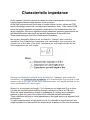
Barring any dissipative effects such as dielectric “leakage” and conductor
resistance, the characteristic impedance of a transmission line is equal to the
square root of the ratio of the line's inductance per unit length divided by the
line's capacitance per unit length:
Barring any dissipative effects such as dielectric “leakage” and conductor
resistance, the characteristic impedance of a transmission line is equal to the
square root of the ratio of the line's inductance per unit length divided by the
line's capacitance per unit length:
.
Where L is in henrys per unit length, C is in farads per unit length and Z o is in ohms.
Consider an electrical signal travelling through a conductor such as a PCB trace.
When the signal encounters a change of impedance (Zo) arising from a change in
material or geometry, part of the signal will be reflected and part transmitted.
These reflections are likely to cause aberrations on the signal which may degrade circuit
performance.
To optimize performance of high speed circuits it is desirable to match the input and
output impedances of devices with the characteristic impedance of the interconnections.