1
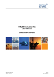
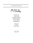
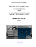
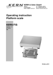
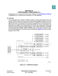
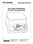
Piccolo Avionics External Interface Specification
Cloud Cap
Technology
8 Fourth Street
PO Box 1500
Hood River, OR 97031
(541) 387-2120 phone
(541) 387-2030 fax
[email protected]
www.uavautopilots.com
Bill Vaglienti
Ross Hoag
Updated April 20, 2005
Cloud Cap
Technology
PO Box 1500, No 8 Fourth Street
Hood River, OR 97031
(541) 387-2120 ph (541) 387-2030
fax
Table of Contents
1
2
Vehicle Interface Connections ............................................................................................. 4
1.1
External I/O – Piccolo/Piccolo Plus/Piccolo II............................................................ 4
1.2
External I/O – Piccolo II............................................................................................... 5
1.3
UHF and GPS Antenna ................................................................................................ 5
1.4
Pitot and Static Pressure Ports .................................................................................... 6
Vehicle Interface Configurations......................................................................................... 6
2.1
3
4
Typical Configuration .................................................................................................. 6
Functional Descriptions........................................................................................................ 7
3.1
DC Inputs....................................................................................................................... 7
3.2
DC Outputs.................................................................................................................... 8
3.3
Serial I/O........................................................................................................................ 9
3.4
PWM Outputs ............................................................................................................... 9
3.5
Controller Area Network Interface............................................................................. 9
3.6
No Connects................................................................................................................... 9
Signal Descriptions.............................................................................................................. 10
4.1
Piccolo and Piccolo Plus ............................................................................................. 10
4.2
Piccolo II ...................................................................................................................... 12
Cloud Cap
Technology
PO Box 1500, No 8 Fourth Street
Hood River, OR 97031
(541) 387-2120 ph (541) 387-2030
fax
Figures
Figure 1 – Piccolo/Piccolo Plus Front Panel................................................................................... 4
Figure 2. - Piccolo II Front Panel.................................................................................................... 5
Figure 3 - Typical Configuration .................................................................................................... 7
Figure 4 - Piccolo DC Inputs and Outputs...................................................................................... 8
Tables
Table 1 P1 - External Interface Connector Pin Assignments ...................................................... 10
Table 2 P2 - Piccolo II MicroDot Connector Pin-out .................................................................. 12
Cloud Cap
Technology
PO Box 1500, No 8 Fourth Street
Hood River, OR 97031
(541) 387-2120 ph (541) 387-2030
fax
Piccolo External Interface
1 Vehicle Interface Connections
1.1 External I/O – Piccolo/Piccolo Plus/Piccolo II
Piccolo, Piccolo Plus, and Piccolo II support a single 44-pin high-density filtered external
interface connector (see Figure 1). The connector chosen, while not the smallest or highest
density available, provides a cost-effective solution in a small footprint whose benefits includes:
•
•
•
•
•
Integral capacitive filtering for minimizing EMI;
A robust “gorilla proof “ electro-mechanical vehicle interface;
Readily available low-cost industry standard mating connectors;
No special tooling required for mating wire harness fabrication;
Provision for continuous shielding across the connector interface for enhanced EMI
protection.
Figure 1 – Piccolo/Piccolo Plus Front Panel
All I/O pins are ESD protected at point of entry and the Maxim RS232 transceiver used provides
enhanced on chip 15kV ESD protection for the two serial interfaces. The main DC input is
reverse polarity as well as ESD protected.
1.1.1 Mating 44-pin connector specification
Connector, D-Sub HD 44 HD-22
•
•
•
CCT part number
Digikey part number
Amp part number
Pins, 22-28 Awg HD-22
760-00330-00
A2078-ND
748366-1
Cloud Cap
Technology
•
•
•
PO Box 1500, No 8 Fourth Street
Hood River, OR 97031
(541) 387-2120 ph (541) 387-2030
fax
CCT part number
Digikey part number
Amp part number
760-00329-00
A2088-ND
748333-4
1.2 External I/O – Piccolo II
Piccolo II has a second external interface connector: a 25-pin Micro-D connector, that provides
additional I/O, serial ports and analog inputs – see Figure 2.
Figure 2. - Piccolo II Front Panel
1.2.1 Mating 25-pin connector specification (Piccolo II only)
The mating connector is supplied with the Piccolo II. It comes with a 18” long pigtail which the
user can mate to as needed. Note: It’s up to the user to properly terminate the unused as well as
the used connections.
Connector, 25 Position Socket Pigtail Harness
•
•
CCT part number
Glenair part number
760-00636-00
MWDM2L-25S-6K1-18B
1.3 UHF and GPS Antenna
Additionally the Piccolo front panel has two SMA coaxial connectors which are used for the
vehicle UHF and GPS antenna connections. It is recommended that low loss RG174 or RG316
cable be used for all external cabling. SMA connectors were chosen due to their availability, ease
of use and robustness.
1.3.1 GPS antenna power for active antennas
The default output voltage for active GPS antennas are outlined below.
•
Piccolo/Piccolo Plus – 3V
Cloud Cap
Technology
•
PO Box 1500, No 8 Fourth Street
Hood River, OR 97031
(541) 387-2120 ph (541) 387-2030
fax
Piccolo II – 5V
Note: Piccolo or Piccolo Plus units can be alternately configured for 5V antenna power. Piccolo
II is 5-volt output only.
1.4 Pitot and Static Pressure Ports
Two pressure port fittings provide the interface to the vehicle pitot/static system. The fittings
accept 3/32 ID tubing. We use Cole Parmer 3/32” ID, 5/32” OD, 1/16” wall lab grade Tygon
tubing (part number 06408-63 type R-3603).
2 Vehicle Interface Configurations
The mix of signals provided on the external interface connector support a multitude of different
vehicle configurations. The most common configuration is outlined below but custom
implementations that meet your specific interface requirements can also be accommodated.
2.1 Typical Configuration
A typical configuration (see Figure 3) would include: 10 PWM outputs for driving control
surfaces; two serial connections (four for Piccolo II); GPS and UHF antenna connections; Flight
termination and or ignition connection; power inputs; and optional payloads attached via the
CAN bus. The two serial links are used for payload and for long-range UHF data links (Piccolo
II includes a dedicated Iridium serial port and a second payload port). Seven unassigned TPU
lines are available (by retasking the control surface lines) for discrete timing, I/O, or PWM. A
switched Deadman’s output is available that can be used for flight termination in the event of
upstream hardware or software failure or as a general purpose On/Off switch for controlling
payloads or other aircraft systems.
Cloud Cap
Technology
PO Box 1500, No 8 Fourth Street
Hood River, OR 97031
(541) 387-2120 ph (541) 387-2030
fax
Up to 10 PWM
outputs for servo s
Over the Horizon Link
1
2
3
4
N
Available on Piccolo II Only
Serial 4
Dedicated Iridium
Communications
GPS
Serial 3
User Payload 2
External
Communications Program Port
Short Range Link
Data and Pilot Uplink
Commands
Serial 1
Piccolo
Avionics
Serial 2
User Payload
Ignition or
Flight
Termination
Hardware-in -Loop
Simulator Interface
Deadman's
8 - 20 VIN
Battery or Generator
Input
CAN bus
User
Payloads
User
Payloads
User
Payloads
Denotes Optional
Component
Figure 3 - Typical Configuration
3 Functional Descriptions
3.1 DC Inputs
3.1.1 Main VIN
Piccolo, Piccolo Plus and Piccolo II were designed for a nominal DC input (VIN) of 12 volts
with an operational input voltage range of 8-20 VDC (see Figure 4).
3.1.2 Servo Power
Piccolo, Piccolo Plus and Piccolo II were designed for a nominal servo power input
(SERVO_Vin_1) of 4.8 or 6.0 volts. This input was designed to accommodate typical RC hobby
servos. Servo load current is limited to a maximum of 2-amps (limited by the 44-pin connector).
If your servo load is expected to be greater than 2-amps and your Piccolo serial number is 555 or
above a second servo power input (SERVO_Vin_2) is available. You can parallel the two input
pins to double your servo load capacity (don’t forget to double the ground pins as well). If you
have questions regarding this configuration please give us a call for further details.
Note: Serial numbers prior to 555 do not support the second servo power input pin
(SERVO_Vin_2) that pin is a No Connect (NC1).
Cloud Cap
Technology
PO Box 1500, No 8 Fourth Street
Hood River, OR 97031
(541) 387-2120 ph (541) 387-2030
fax
x2
Servo Vin 1
Servo Vin 2
(4.8-6 Volts)
Voltage and
Current
Measuremet
Servo power pass
through, 5-volts
nominal
x7
Servo Vout
Deadman's
Output
x1
Deadman's
Switch
(44 Pin)
External
Interface
Keep Alive Signal
From MPC555
Schottky Diode
12VDC
Main DC Input
VIN (8-20)
Volts
Voltage and
Current
Measuremet
Piccolo On-Board
Regulators and
Sub-Systems
TVS Diode
x12
GND
All grounds are connected
Figure 4 - Piccolo DC Inputs and Outputs
3.2 DC Outputs
The interface connector provides seven unswitched (SERVO_Vout) and one switched
(Deadman’s Output) DC outputs.
3.2.1 Servo DC Outputs
These outputs are used to power the vehicle control surface actuators, typically RC model servos.
The voltage on these outputs will track whatever voltage is applied to the SERVO_Vin pin(s) –
the Piccolo acts as a pass through and in the process measures both the voltage and current of
this user supplied voltage rail.
3.2.2 Deadman’s Output
The Deadman’s switch consists of a power MOSFET driven by a watchdog timer circuit. The
deadman’s switch requires that software periodically service a hardware line to keep the switch
active. Hence if the system fails, either due to software or hardware failure, the Deadman’s
switch turns off. This switch can be connected to an ignition system, or other flight termination
system, and so provides a measure of safety in the event that the system fails. Please refer to the
“Piccolo User’s Manual” for further details on how to setup and use the Deadman’s output. The
MOSFET switch can drive up to a 3-amp load and is powered from SERVO_Vin. When
activated (turned on) it will provide a voltage level of SERVO_Vout (4.8-6.0 volts nominal),
when deactivated (turned off) it will float the output – disconnect the load.
Cloud Cap
Technology
PO Box 1500, No 8 Fourth Street
Hood River, OR 97031
(541) 387-2120 ph (541) 387-2030
fax
3.3 Serial I/O
The Piccolo Plus external interface connector supports two dedicated RS232 universal
asynchronous receiver transmitter (UART) serial ports; one for programming and/or general
serial I/O (115K baud max); and the other for general serial I/O or payload communications
(56K baud max). Note: any of the other TPU lines or PWM, if unused, can also be configured
for use as GPIO, timing I/O or as PWM outputs.
In addition Piccolo II, which has an additional external interface connector, provides a dedicated
4-wire RS232 port for connection to an Iridium satellite terminal as well as and a second payload
serial port.
3.4 PWM Outputs
The interface connector offers the option to directly drive up to 10 standard RC servos providing
PWM outputs, powers and grounds for each. The PWM outputs are divided into two banks:
•
•
Bank 1 - PWMSM[0-4] are nominally PWM outputs used for servos 1-5. The can also
be configured for GPIO or timing output
Bank 2 - TPU_A[0-4] are nominally PWM outputs sued for servos 6-10. They can also
be configured for GPIO, or timing input and output.
3.5 Controller Area Network Interface
A Controller Area Network (CAN) serial interface is also provided for bussed or multi-drop
applications. The CAN bus is a robust two wire differential serial bus designed for use in high
EMI environments. It has seen wide use in automotive and industrial control applications and
should prove to be well suited for UAV applications. The CAN bus is also used to provide the
link between the Piccolo avionics and the Piccolo hardware in the loop simulator1. Follow on
products will include a number of payload modules that will connect using this interface. We
envision a 5-wire interface CANH, CANL, V1, V2, GND plus an overall shield. Nominally V1
and V2 would be 5V and 12V respectively.
Piccolo II provides access to a second CAN bus on its additional interface connector.
Functionality is TBD – added for custom applications.
3.6 No Connects
If you have a Piccolo or Piccolo plus prior to serial number 555 you have access to two no
connects (NC1 and NC2) which if needed can be used for custom applications – call CCT for
further details if you need to use them.
If you have a Piccolo Plus or Piccolo II serial number 555 or above, these pins are configured as
secondary servo power inputs (SERVO_Vin_2 and GND). This was added to provide for
operating with larger servo loads (current loads above 2-amps) . See section 3.1.2 for further
details.
1
Hardware in loop simulation is arguably one of the most important features of any UAV development system.
Cloud Cap
Technology
PO Box 1500, No 8 Fourth Street
Hood River, OR 97031
(541) 387-2120 ph (541) 387-2030
fax
4 Signal Descriptions
4.1 Piccolo and Piccolo Plus
Table 1 P1 - External Interface Connector Pin Assignments
TYPE
O
O
O
O
PWR/GND
CAN
SERIAL COMMS
O
I
I
I
Program/User Mode Control Input - MPIO32B5
Hardware Reset - actve low
Ground
RS232 Ext Com/Program Port TX
RS232 Ext Com/Program Port RX
Before serial number 555, this is a no-connect
Main DC Input - 5.5-20 Vin
SPARE I/O
O
O
I/O
I/O
I/O
I/O
I/O
O
O
I
O
5
5V
5V
O
O
4
I
I
O
O
3
I/O
I/O
0
I
I/O
I/O
LEVEL FUNCTION
Gnd for servo 1
!
Power for servo 1
Servo 1 signal output - Left Aileron
5V
Gnd for servo 2
!
Power for servo 2
Servo 2 signal output - Left Elevator
5V
Gnd for servo 3
!
Power for servo 3
Servo 3 signal output - Left Throttle
5V
Gnd for servo 4
!
Power for servo 4
Servo 4 signal output - Left Rudder
5V
Gnd for servo 5
!
Power for servo 5
Servo 5 signal output - Left Flap
5V
5V
Servo 6 signal output - Right Aileron
5V
Servo 7 signal output - Right Elevator
5V
Servo 8 signal output - Right Throttle
5V
Servo 9 signal output - Right Rudder
Servo 10 signal output - Right Flap
5V
!
!
Servo power input 4.8-6V nominal
Servo power switched by deadman circuit
Ground
Ground
Ground
CAN Ground
CAN
CAN A Serial High
CAN
CAN A Serial Low
232
Payload 1 TX -User RS232 Output - TPU_B[0]
232
Payload 1 RX - User RS232 Input - TPU_B[1]
5V
User Configurable I/O
5V
User Configurable I/O
2
NAME
GND
SERVO_Vout
PWMSM[0]
GND
SERVO_Vout
PWMSM[1]
GND
SERVO_Vout
PWMSM[2]
GND
SERVO_Vout
PWMSM[3]
GND
SERVO_Vout
PWMSM[4]
TPU_A[0]
TPU_A[1]
TPU_A[2]
TPU_A[3]
TPU_A[4]
SERVO_Vout
SERVO_Vout
SERVO_Vin_1
Deadman's output
GND
GND
GND
CAN_GND
CAN_HI_A
CAN_L0_A
TXD_RS232
RXD_RS232
TPU_B[2]
TPU_B[3]
GND
*PROGRAM/USER
*HRESET
GND
SCI_2_TX_232
SCI_2_RX_232
SERVO_Vin_2 / NC1
VIN
GND
SERVO_GND / NC2
1
PIN
15
30
44
14
29
43
13
28
42
12
27
41
11
26
40
39
38
37
36
35
25
24
23
6
10
9
8
7
22
21
34
33
5
20
4
19
18
3
32
31
16
1
2
17
Before serial number 555, this is a no connect
PWMSM[0-4] (0-5 volt output) In the default mode these are configured as PWM outputs and
are used to control the actuators on left side of the airplane.
SERVO_Vin_1 (4.8-6.0 volt input) User supplied input voltage used to power the servos
Cloud Cap
Technology
PO Box 1500, No 8 Fourth Street
Hood River, OR 97031
(541) 387-2120 ph (541) 387-2030
fax
SERVO_Vout (output) DC output whose voltage matches the applied SERVO_Vin inputs.
Nominally these are used as servo power pins.
Deadman's output (output) Switched DC output whose output voltage matches the applied
SERVO_Vin_1 input DC voltage. ON/OFF controlled via software by an onboard Deadman’s
circuit. Typically used for ON/OFF control of an ignition or flight termination system.
TPU_A[0-4] (0-5 volt input/output) In the default mode these are configured as PWM outputs
and are used to control the right side of the airplane. They can be independently configured for
GPIO, TTL level serial communications, or timing if not needed for actuator control.
TPU_B[2-3] (0-5 volt input/output) In the default mode these are configured as RPM inputs for
a left and right engine respectively. They can also be independently configured for GPIO, TTL
level serial communications, or timing.
CAN_HI_A - (CAN level I/O)
CAN_LO_A - (CAN level I/O)
CAN_GND - Same as system ground (GND).
TXD_RS232 (RS232 output) Driven by TPU B CH0 on the MPC555 – Payload 1 transmitter.
RXD_RS232 (RS232 input) Received by TPU B CH1 on the MPC555 – Payload 1 receiver.
*PROGRAM/USER (0-3.3 volt input) When held low during a reset the MPC555 boots in
monitor mode from which application code can be loaded to flash; When left floating or driven
high during a reset causes the MPC555 to boot and run user application code. The pin has a 10k
pull-up to 3.3 volts.
*HRESET (0-3.3 volt input) When pulled low forces the MPC555 into a hard reset. The pin
has a 10k pull-up to 3.3 volts.
SCI_2_TX_232 (RS232 level output) Driven by SCI CH2 TX on the MPC555. Each SCI is a
full-duplex universal asynchronous receiver transmitter (UART) serial interface. External
communications/Programming serial transmitter.
SCI_2_RX_232 (RS232 level input) Received by SCI CH2 RX on the MPC555. Each SCI is a
full-duplex universal asynchronous receiver transmitter (UART) serial interface. External
communications/Programming serial receiver.
NC[1-2] (User defined) User defined no connect pins for future applications on Piccolo and
Piccolo Plus serial numbers below 555. On Piccolo Plus and Piccolo II’s serial numbers 555 and
above NC1 and NC2 are configured as secondary inputs for servo power, SERVO_Vin_2 and
SERVO_GND respectively.
VIN (8-20 volt input) DC input voltage used to power the onboard 5.5-volt and 3.3-volt
switching regulators.
Cloud Cap
Technology
PO Box 1500, No 8 Fourth Street
Hood River, OR 97031
(541) 387-2120 ph (541) 387-2030
fax
GND Common ground tied to the internal ground plane of the avionics and the shell of the
main interface connector.
4.2 Piccolo II
Table 2 P2 - Piccolo II MicroDot Connector Pin-out
PIN
24
13
12
11
10
9
22
23
21
19
17
15
8
18
20
7
6
16
5
4
14
3
2
1
25
NAME
CAN_LO_B
CAN_HI_B
AIN0
AIN1
AIN2
AIN3
AGND
AGND
TPU_B8
TPU_B9
TPU_B10
TPU_B11
GND
GND
GND
TXD1_232
RXD1_232
GND
TXD2_232
RXD2_232
GND
TXD3_232
RXD3_232
GND
No Connection
TYPE
I/O
I/O
I
I
I
I
LEVEL
CAN
CAN
5V
5V
5V
5V
I/O
I/O
I/O
I/O
5V
5V
5V
5V
O
I
RS232
RS232
O
I
RS232
RS232
O
I
RS232
RS232
FUNCTION
Serial TX/RX
Serial TX/RX
10 bit anlog input
10 bit anlog input
10 bit anlog input
10 bit analog input
Analog ground
Analog ground
GPIO3
GPIO4
GPIO5
GPIO6
Ground
Ground
Ground
Iridium TXD
Iridium RXD
Ground
Iridium DTR
Iridium CD
Ground
Payload 2 RS-232 Tx
Payload 2 RS-232 Rx
Ground
CAN_HI_B (CAN level I/O)
CAN_LO_B (CAN level I/O)
AIN[0-4] (0-5 volt inputs) User configurable 10-bit analog inputs. Each input has a 100pF
capacitor to ground and a 1k ohm series resistor. See the “Piccolo User’s Guide” for further
details on configuration and use.
AGND – Returns for the four analog inputs.
TPU B[8-11] (0-5 volt I/O) Can also be independently configured for GPIO, or timing.
GND – Returns for any of the digital I/O.
TXD1 (RS232 output) Iridium transmit data.
RXD1 (RS232 input) Iridium receive data.
TXD2 (RS232 output) Data Terminal Ready (DTR) output to Iridium unit.
RXD2 (RS232 input) Carrier Detect (CD) from Iridium unit.
TXD3 (RS232 output) Payload 2 transmit data.
RXD3 (RS232 input) Payload 2 receive data.