1
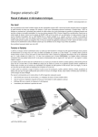
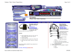
P7689 / P7789
Level 1 & 2 Service Manual
Rev 1.4
CONTENTS
Page Number
SECTION 1: GENERAL
1.1
1.2
1.3
Introduction
Motorola service policy for P7689 in warranty
General Safety Information
v
vi
vii
SECTION 2: P7689 DESCRIPTION
2.1
2.2
2.3
2.4
2.5
2.6
2.7
Specifications of P7689
P7689 Overview
Connector Pinout
Talk time, Weight and Volume Matrix
Battery Charging Times
Battery Technology
Physical Dimensions
2
3
7
7
8
8
8
SECTION 3: FEATURE LIST
3.1
List of Features available
10
3.2
3.3
3.4
3.5
3.6
3.7
3.8
3.9
3.10
3.11
3.9
Menu
Phone Book
Call Related Features
Messages
Phone Set Up (Ext Menu – Off)
Phone Set Up (Ext Menu – On)
Network selection
Call Meters
Date Book
Games
Accessory set-up
10
10
11
12
13
14
15
15
16
16
16
SECTION 4: DISASSEMBLY & PARTS
4.1
4.2
4.3
4.4
4.5
4.6
Dissasembly Introduction
Recommended Tools
Disassembly Procedure
Assembly procedure
Exploded Parts diagram (AAUG175AA)
Part Numbers
18
18
18
18
19
20
SECTION 5: SIM CARDS AND SECURITY
5.1
5.2
5.3
5.4
5.5
Manual test mode
Live Sim Card
Personality Transfer
GSM Test Command
Identity and Security
42
42
42
44
45
P7689 / P7789
SECTION 6: REPAIR & TEST PROCEDURES
6.1
6.2
6.3
6.4
6.5
6.6
6.7
Repair introduction
Mechanical repairs
Basic modular troubleshooting
Software Upgrade
Flexing
Testing on HP 8922
Testing IrDA Port
47
47
47
50
50
51
51
SECTION 7: ACCESSORIES
7.1
7.2
7.3
Accessory Statement
Mid Rate Charger Information
Accessory Listing
54
54
54
SECTION 8: SALES MODELS
8.1
Sales Models
56
SECTION 9: GLOSSARY OF TERMS
9.1
iii of 59
List of Abbreviations
60
GSM Field Service Support
P7689 / P7789
SECTION 1: GENERAL
iv of 59
GSM Field Service Support
P7689 / P7789
1.1
Introduction
This manual is intended for use by technicians familiar with similar types of equipment. It contains all
service information required for the equipment described and is current as of the printing date.
Although there is a P7689 Flat and a P7789 Flipped version of this unit we shall just refer to one
model from now on, the P7689.
The scope of this document is to provide the reader with basic information relating to the P7689, and
also to provide procedures and processes for repairing the units up to and including Level 2 repair.
Level 1 and 2 repairs involve the following activities to be carried out: •
•
•
•
•
•
•
Unit swap out
Repairing of mechanical faults
Basic modular troubleshooting
Testing and verification of unit functionality
Upgrading software
Flexing units
Initiate warranty claims and send faulty modules to Level 3 or 4 repair centres.
Computer Software Copyrights
The Motorola products described in this instruction manual may include copyrighted Motorola
computer programs stored in semi-conductor memories or other media. Laws in the United States and
other countries preserve for Motorola certain exclusive rights for copyrighted computer programs,
including the exclusive right to copy or reproduce in any form the copyrighted computer program.
Accordingly, any copyrighted Motorola computer programs contained in the Motorola products
described in this instruction manual may not be copied or reproduced in any manner without the
express written permission of Motorola. Furthermore, the purchase of Motorola products shall not be
deemed to grant either directly or by implication, estoppel, or otherwise, any license under the
copyrights, patents or patent applications of Motorola, except for the normal non-exclusive, royalty
free license to use that arises by operation of law in the sale of a product.
v of 59
GSM Field Service Support
P7689 / P7789
1.2
Motorola Service Policy for P7689 in warranty
1.2.1
Warranty:
Product will be sold with the standard 12 months warranty terms and conditions. Accidental damage
misuse, retailers extended warranties will not be supported under warranty. Non warranty repairs will
be available at agreed fixed repair prices.
Proof of purchase will be required to validate warranty claims.
1.2.2
Out of Box Failure Policy
The standard OOB failure criteria will apply. Customer units that fail very early on, after date of sale,
are to be returned to Manufacturing for root cause analysis, to guard against epidemic criteria.
Manufacturing to bear the costs of early life failure.
1.2.3
Product Support
Customers original units will be repaired but not refurbished as standard. Appointed Motorola Service
Hubs will perform warranty and non-warranty field service for level 2 (assemblies) and level 3 (limited
PCB component). The Motorola HTC centres will perform level 4 (full component) repairs.
1.2.4
Customer Support:
This will be available through dedicated Call Centres and In Country Help Desks.
Product Service training should be arranged through the local Motorola Support Centre.
1.2.5
Replacement Parts Ordering
Only centres authorized to carry out repairs will be able to purchase spare parts. Orders for spare parts
from Hub’s and Hi-Tech Centres should be placed with the regional Motorola Parts Distribution
Centre.
vi of 59
GSM Field Service Support
P7689 / P7789
1.3
General Safety Information
1.3.1 Portable Operation
• DO NOT hold the radio so that the antenna is very close to, or touching, exposed parts of the body,
especially the face or eyes whilst transmitting. The radio will perform best if it is held in the same
manner as you would hold a ‘land’ telephone handset, with the antenna angled up and over your
shoulder.
•
DO NOT operate the portable phone in an aircraft. Switch off your telephone. The use of a cellular
telephone in an aircraft may be dangerous to the operation of the aircraft, disruption of the Cellular
Network may occur, and is illegal. Failure to observe this instruction may lead to a suspension or
denial of Cellular Telephone Service to the offender, or legal action, or both.
1.3.2 Mobile/Portable Operation - Telephone use in Vehicles:
• All equipment must be properly grounded according to installation instructions for safe operation.
•
Users are advised to turn off their equipment when at a refueling point.
•
Safety is every driver’s responsibility. Cellular telephones should only be used in situations in
which the driver considers it safe to do so.
1.3.3 General
• DO NOT allow children to play with any radio equipment containing a transmitter.
•
DO NOT operate this equipment near electrical blasting caps or in an explosive atmosphere.
Mobile Telephones are, under certain conditions, capable of interfering with blasting operations.
When you are in the vicinity of such work, look out for and observe signs cautioning against
mobile radio transmission. If transmission is prohibited, you must turn off your mobile telephone
to prevent any transmission.
In standby mode the mobile telephone will automatically transmit to acknowledge a call if it is not
turned off.
•
Refer to the appropriate section of the product user manual for additional pertinent safety
information
•
All equipment should be serviced only by a Motorola qualified technician.
vii of 59
GSM Field Service Support
P7689 / P7789
SECTION 2:
P7689
DESCRIPTION
8 of 59
GSM Field Service Support
P7689 / P7789
2.1
Specifications of P7689
General
Function
Frequency Range GSM
Frequency Range DCS
Frequency Range PCS
Channel Spacing
Channels
Modulation
Transmitter Phase Accuracy
Duplex Spacing
Frequency Stability
Operating Voltage
Transmit Current
Stand-by Current
Dimensions
Size (Volume)
Weight
Temperature Range
Transmitter
Function
RF Power Output
Output Impedance
Spurious Emissions
Receiver
Function
RF Level
RX bit error rate (100 k bits)
Channel Hop Time
Time to Camp
Speech Coding
Function
Speech Coding Type
Bit Rate
Frame Duration
Block Length
Classes
Bit Rate with FEC Encoding
9 of 59
Specification
880-915 MHz TX (with EGSM)
925-960 MHz RX
1710-1785 MHz Tx
1805-1880 MHz Rx
1850.2 – 1909.8 MHz Tx
1930.2 – 1989.8 MHz Rx
200 kHz
174 GSM/374 DCS carriers with 8 channels per carrier
GMSK at BT = 0.3
5 Degrees RMS, 20 Degrees peak
45 MHz GSM 95MHz DCS 80MHz PCS
+ 0.10 ppm of the downlink frequency (Rx)
Full Rate PSU = 4.4V +/- 5%
(During Charging = VBatt +/-5% 6.63V
Mid Rate Charger = 5.9V +/- 0.3V
CLA Supply = 4.4V
Battery Operating Voltage = 2.85V(Radio Shut Down voltage)
To 4.2V Max
Typically 250 ma avg, 1.0A peak
Typically 7.0 ma (DRX2)
130mm x 46mm x 23 mm (max. Thk.)
97 cc with Dao 550 mAh LiO Battery
102.9g with Dao 550 mAh LiO Battery
-10C to +55C
Specification
33 dBm + 2dB GSM/ 30 dBm + 2 dB DCS
50 ohms (nominal)
-36 dBm from 0.1 to 1 Ghz
-30 dBm from 1 to 4 Ghz
Specification
-102 dBm
< 2%
500 microseconds
Approximately 5-10 seconds
Specification
Regular Pulse Excitation / Linear Predictive Coding with Long
Term Prediction. (RPE LPC with LTP).
13.0 k bps
20 ms
260 bits
Class 1 bits = 182 bits. Class 2 bits = 78 bits
22.8 k bps
GSM Field Service Support
P7689 / P7789
2.2
P7689 Overview
The P7689 is of the Tri Band technology range allowing roaming using the GSM 900 / 1800 / 1900
bands. (see below) The unit is a follow on but will not replace the L7389 / L7489. As will be seen, the
form factor for the P7689 is very different to P7389 or V2088. The unit will still be marketed within
the Timeport brand, aimed at the organised business users. The following are a few of the main selling
features that will be included with the unit.
• Using the Whitecap lower voltage technology this offers good standby and talk times(see below)
• Extended GSM channels
• Tri-Codec allowing Full Rate / Half Rate / Enhanced Full Rate modes of transmission.
• SIM Toolkit.(STK 2.4)
• Enhanced Infrared Data link (see below)
• 3 Pin RS232 connection.
• PIM _ Personal Information Manager – basic diary function
• 96 x 64 row full graphics TMF film (for enhanced contrast) with contrast control. (larger display
that P7389)
• Internal Headset
• Speaker Dependant Voice recognition (see below)
• VibracallTM
• VoicenotesTM Alarmed with selective erase – 2 minutes
• WAP 1.1. compliant
• Datebook
• Answering Machine
• Silent Answer
• Calling Name Presentation
• Display Animation
• Scheduled Call Divert
• Concatenated SMS
• Smart Card support – E- Commerce
• Blue Backlights
• Chromed Keypad for OK and C Keys, chrome rocker MENU key and all other keys, film type
with transparent numbering.
• New Ringer Tones
• Programmable Ringer Tones
• Enhanced Chinese Key entry
• New Games – (see below)
IrDA – Infra red Data Association, This feature will allow the user to link their mobile phone to their
computer terminal. This will allow the user to upload and download information, such as phonebok
information, SMS messages, FAX data etc… without the requirement for cables. The unit can also
communicate with other IrDA devices such as pagers and other mobile phones.
Perfect alignment of the beam is not required due to the spread of the beam.
IP SMS allows SMS messages to be constucted on a PC then downloaded to the P7689 to be
transmtted.
IP Phonebook allows very easy and extremely flexible download / upload of phonebook information,
enabling select phonebooks available to each user, which can be quickly changed for example when
travelling to different areas.
The last 10 calls made and received can also be downloaded allowing databases to be created.
The P7689 can be placed into IrDA mode via either the quick access menu or through the Phone Set up
menu structure ‘ Activated’ will appear on the screen once the feature has been selected followed by
‘Connection Made’ once transfer of data is available between the P7689 and the other device. The
P7689 software allows more devices to be synchronised with phone e.g.Win NT, Psion and Palm.
10 of 59
GSM Field Service Support
P7689 / P7789
Speaker Dependant Voice Recognition – This feature allows ‘Voice Tags’ to be allocated to upto 25
names within the users phone memory and also upto 15 Voice tags be allocated to the quick access
functions. The unit must be ‘trained’ for this function (ie the voice tags must first be read into the
phones memory twice before recognition can be made.)
Two main points whilst using this option.
*THERE WILL BE NO SERVICE DURING ‘TRAINING’ WHICH MEANS THE USER CANNOT
RECEIVE OR MAKE CALLS DURING THIS TIME.
*THE VOICE TAGS CAN ONLY BE ADDED TO THE PHONES MEMORY, AS GSM DOES NOT
ALLOW THE OPTION TO STORE VOICE TAGS ONTO THE SIM CARD.
Voice tags can be added to the phones memory using the usual name addition methods ie via the
phonebook menu structure, using the M+ key, or using the quick access keys.
To make a call to a person allocated with a voice tag, the smart button must first be pressed, then the
P7689 will ask for a name, if the name is recognised, then the name will be repeated and displayed on
the screen. A call can then be placed.
For access to one of the quick access functions the quick access key must first be pressed, a name will
then be asked for, if the name is recognised e.g. Battery Meter then the name will be repeated and the
corresponding feature e.g. the battery meter will be displayed on the screen.
If 2 names are too alike then the unit will request another name.
CUG (Closed User Group) This is a network application which allows a select group of users only to
use a particular group of mobile units e.g. In the circumstance where a manager of a field service team
only wants the team to be able to call other users within his team (or CUG).
Phase 2 USSD (Unstructured Supplementary Services Data) – This is an application whereby
pressing a certain key or combination of keys whilst in idle mode ie not in a call can access certain
network functions such as helplines etc...
•
WAP 1.1 Compliancy (Wireless Application Protocol) - WAP 1.1 Wireless Application
Protocol
Simplified WAP
Architecture
‘The Internet’
Content Servers
Phone with
browser
•
Wireless
connection
(GSM Data call
is preferred)
WAP
Gateway
ISP
account
In the WAP environment this is how the access is made.
1. The request for information is made in WML (Wireless Markup Language) derived from HTML.
2. Request is passed to WAP Gateway, which retrieves the information from the server in standard
HTML (which is then filtered to WML) or if available WML format.
3. The information is then passed the cellular user, via the cellular network provider.
•
There will be 5 Data parameters that the user will be able to edit:
-Baud rate - between 2400 and 14400
11 of 59
GSM Field Service Support
P7689 / P7789
-Idle time out
-Line type
-Phone Number
-Connection type
•
For image download, the bitmap image will be downloaded as text and if the image is larger than
the screen then only part of the image will be displayed
• Ways to access Browser - Quick access key and Feature Menu
During browser mode, if incoming call is received then the browser will be paused with the user having
the option to resume after the call.
Simplified Alpha Text Entry - This gives the allowance to use all forms of Roman and Chinese Key
entry on a 96 X 54 display.
At present only Latin based characters can be entered using the multi tap key entry.
There are 3 forms of CKE (Chinese Key Entry):
• Pin Yin - Simplified Chinese (Mainland China)
• Bo-po-mo-pho - Complex Chinese (Taiwan)
• Stroke based method for both Simple and Complex
• Can be used with phone book and SMS features
• European and Pan American models will be able to switch between Roman and Latin Key Entry
• Asian Models will be able to switch between all Key entries.
Calling Name Presentation - This is an improvement on the existing name presentation.
• At present name from phone book is displayed by comparing last 8 digits of Number
• New feature will show name as sent by the network. This is up to 80 characters, but will be
shortened to 12 for the phonebook.
• This functionality must be subscribed to with network.
• Caller can restrict this
• On call arrival phone Number is compared to phonebook if match is found but name is not
allocated then callers name will be stored.(However if there is any text against that number it will
not be overwritten)
Display Animation - Aimed at physically showing the customer is executing commands.
Existing animations are for Power up and Down sequences.
• New animations • Incoming / sending call
• Incoming / sending SMS
• IrDA Quick Access icon
Call Divert Interrogation - This function is just a more accurate way of ensuring that the caller is
diverted to the correct number, this is mainly achieved through the co-operation of the network
providers.
Concatenated SMS - Concatenated: A series of linked events
Increases the amount of characters that can be sent and received from the phone.
Currently can send 1 SMS of 160 characters and the SIM can store 10 of these.
New functionality will support 5 X 153 Character messages and the SIM will be able to hold between
30 and 75 slots dependant on type of card and memory already allocated, each slot will hold 160
characters.
Connectivity – The P7689 will support the Communicate soft Modem via the RS232 cable
56K global Modem and AT Command parsing via IrDA.
12 of 59
GSM Field Service Support
P7689 / P7789
Games – There will be 3 games supported, these being :
• Brick
• Baccarat
• Tower of Hanoi
13 of 59
GSM Field Service Support
P7689 / P7789
Fig 2.1 Mechanical
pictorial Overview
Rear latch
Belt Clip
Recess
Antenna
Voice notes TM
button
Screw
Locations
Battery
Contacts
SIM Contacts
Accessory
Connector
Chromed Keys
Mic Port
96 x 64 LCD
IrDA Port
Speaker Port
Service
Indicator
Internal Headset
Socket
Volume Keys
Smart Key
Rocker Key
There will be 4 colours of front housing – Metallic Silver / Metallic Titanium / Metallic Graphite /
Metallic Aluminium.
14 of 59
GSM Field Service Support
P7689 / P7789
2.3 Connector Pinouts
1
14
Charger Socket Pin Layout
1.GND
3.GND
5.MAN_TEST_AD
7.RS232_RX
9.ON_2*
11.DSC_IN*
13.DSC_EN
15.GND
2.4
2.SW_RF
4.BATT_FDBK
6.RS232_TX
8.CHG_EN
10.GND
12.DOWNLINK
EXT B+
Talk Times, Weight and Volume Matrix
Volume (cc)
Weight (g) Talk Time
(min)*
Standby Time
(hours)*
with Battery
97 cc
102.6 g
120-180
40-130
550 mAh LiIon
102 cc
106.2 g
120-210
45-150
Slim LSQ6 600mAh Li Ion
113 cc
129.5 g
210-330
70-240
LSQ8 900 mAh Li Ion
All battery performance times are approximate and will vary depending on network
configuration, band and status, and the functions selected. Times are quoted as a range
from DRX=2 to DRX=9. Support of DTX mode is dependent on network support and
may not be available in all areas.
15 of 59
GSM Field Service Support
P7689 / P7789
2.5
Battery Charging Times
Identical to Leap, maximum charge times shown.
Battery
Leap Mid Rate Travel Charger to
90% charge (LiIon only)
LSQ6 600 mAh LiIon
120 min
LSQ8 900 mAh LiIon
230 min
Dao 550 mAh LiIon
110 min
2.6
Battery Technology
Battery technology will use the 3.6 V platform and use label-wrapped batteries. Jade
will also employ battery safety that will not allow the phone to charge a non-Motorola
battery.
The P7689 will allow battery charging via mid rate charger or EP charger via the
Hirose connector.
2.7
Physical Dimensions
Dimensions
P7789
P7689
Length
130 mm
130 mm
Depth
46 mm
25 mm
46 mm
23 mm
Volume
Weight
Depth
Volume
108 cc
107 g
26 mm
112 cc
97 cc
102.9 g
24 mm
102 cc
Weight
Depth
110 g
27 mm
106.2 g
26 mm
Volume
124 cc
113 cc
Weight
130 g
129.5 g
Width
Extra slim battery door
With Slim LiIon battery
(550 mAH)
Slim battery door
With LSQ6 (600 mAH
LiIon)
Thick battery door With
LSQ8 (900 mAH LiIon)
16 of 59
GSM Field Service Support
P7689 / P7789
SECTION 3: FEATURE LIST
17 of 59
GSM Field Service Support
P7689 / P7789
3.1
List of Features Available
Below is the list of Menu functions available at present.
Menu
1st Generation Menu
Phone Book
Network
Selection
Date Book
Call Related
Features
Call Meters
Games
Messages
Phone Setup
nd
2 Generation Menu
3rd Generation Menu
4th Generation Menu
5th Generation Menu
6th Generation Menu
Access
Internet
Accessory
Setup
Only Available
with Headset
or Car Kit
connected
PHONE BOOK
Voice Dialing
Find Entry
by Name
Personal Numbers
Last 10 Calls
1.Call Number
2.Switch View
3.Add to Phone memory
4.Add to SIM Memory
Missed Calls
Answered Calls
Made Calls
Find Entry
By Location
Enter
Location
Add Entry
Add to phone memory
My phone number(s)
Show Services
One-Touch
Dial Setting
18 of 59
1.Call Number
2.Modify Name or number
3.Erase name or number
4. Add or Edit Voice Tag
5. Delete Voice Tag
6. Create Phone book Group*
7.Modify Phone Book group*
* Entry by name only
1.Call Number
2.Switch View
Erase all numbers
Fixed dialing
Enter Name
Add Voice Tag
Add to SIM Card Memory
View fixed dial list
Setup
fixed
Dialing
Check Capacity
Enter
Pin2
1.To Phone Memory
2.To SIM memory
3.To Fixed Dial list
1.On
2.Off
3.Edit Entry
4.Add Entry
5.Erase Entry
Check phone Capacity
Check SIM Capacity
Prevent access
1.No memory restrictions
2.To SIM card memory
3. To Phone Memory
4. To Phone and Sim Memory
SIM Copy
1.SIM Card to Phone Memory
2.Phone to SIM card memory
GSM Field Service Support
P7689 / P7789
CALL RELATED
FEATURES
Show battery meter
Restrict my
Phone number
1.Show ID on next call
2.Restrict ID on next call
Call Diverting
Talk and Fax
1.On
2.Off
Call waiting
1.On
2.Off
Call Barring
Bar outgoing calls
1.Int’l Calls
2.Int’l Calls Except home
3.All Calls
4.Off
Bar Incoming Calls
1.When Roaming
2.All Calls
3.Off
Change Bar password
Cancel all barring
Key Answer
Only
(Flip Only)
1.On
2.Off
Divert Voice calls
Divert Fax Calls
Divert Data Calls
1.On
2.Off
1.On
2.Off
Divert when unavailable
1.On
2.Off
Divert all Voice calls
1.On
2.Off
Detailed Diverting
Cancel all diverting
If Busy
1.On
2.Off
If not reachable
1.On
2.Off
If No Answer
1.On
2.Off
Scheduled Diverting
19 of 59
GSM Field Service Support
1.On
2.Off
P7689 / P7789
Messages
Call Voicemail
Answering
Machine
Received messages
Play New
Switch View
Play All
Delete Message
Play Announcement
Retrieve Number
Record Announcement
Reply to message
Answering
Machine –
On / Off
Return Call
Edit Message
1.Send Message
2.Store Message
Answer on X Rings
Mode – Audio/Silent
Go to Next message
Delete all messages
Outgoing Messages
Switch View
Send message
Edit message
1.Send message
2.Store message
Delete message
Go To Next Message
On
Cell broadcast
Message Settings
1.Voicemail Number
2.Service Centre
3.Expiry Period
4.Outgoing message type
Off
1.Channel Index
2.Delete all Channels
Channel List
Language List
Message Editor
Voice notes
Edit Message
Play Voice Notes
Show Time Available
Erase all Voice Notes
20 of 59
GSM Field Service Support
Send message
Enter Number
Store Message
Stored to Outgoing
Go To Next
P7689 / P7789
PHONE SETUP
Ext. Menu - Off
Select phone line
Adjust Ring volume
Ring or Vibrate
1.Ring only
2.Vibrate only
3.Vibrate then Ring
4.No Ring or vibrate
Standard Tone
.
.
Music Tone
Set Ringer Tone
Set Ringer Tone 2
Set Alarm Ringer Tone
Set Message Alert Tone
Silent Answer
1.Record Message
2.Review Message
3.Delay Period
Edit Music Tone
Quick Access set up
Phone Lock
Activate IR Port
1. Assign key to feature
2. Add or Edit Voice Tag
3. Delete Voice Tag
Automatic Lock
Lock Now
Change Unlock mode
Adjust Contrast
Require SIM card pin
1.On
2.Off
3.Change SIM pin Code
Change SIM PIN2 Code
New security code
Extended menus
21 of 59
1.Play Music
2.Save Music
3.Erase Music
4.Change Tempo
5.Send as SMS
1.On
2.Off
GSM Field Service Support
1.On
2.Off
P7689 / P7789
PHONE SETUP
Ext. Menu - On
Extended menus
1.On
2.Off
Show Time and Date
Set Time and Date
Set Time Format
Language Selection
English
.
.
Automatic
Entry Method Selection
Battery saving mode
1.On
2.Off
Set Animation
1.On
2.Off
Select Keypad tones
1.Normal Tones
2.Single Tones
3.No Tones
Phone Status
1.Status review
2.Master reset
3.Master Clear
22 of 59
GSM Field Service Support
P7689 / P7789
NETWORK
SELECTION
1.Change to 900 / 1800
2.Change to 900
3. Change to 1800
4. Change to 1900
Change Band
Select band
Available
Networks
1.Register Now
2.Make Preferred
Network Search
Registration
Preferences
1.Automatic Search
2.Manual Search
Frequency of
Search
1.Slow Search
2.Medium Search
3.Fast Search
4.Continuous Search
Add network
to List
1.Choose From Available
2.Choose From Known
3.Add new Network Code
Show List of
Networks
1.Move to New Location
2.Delete Selection
Preferred
Networks
Find New
Networks
CALL METERS
Show Call charges
1.Show last call
2.Total for all calls
3.Credit remaining
Show call timers
1.Show last call
2.Total for all calls
3.Reset all timers
Set audible Call Timers
Single Alert Timer
1.On
2.Off
Repetitive Timer
1.On
2.Off
Set in call Display
1.Show time per call
2.Show Charge per call
3.Show total Call charges
4.No in call display
Call charge settings
Reset Call charges
Set Total Charge Limit
1.On
2.Off
Set Charge Type
1.Units
2.Currency
Lifetime Timer
23 of 59
GSM Field Service Support
P7689 / P7789
DATE BOOK
View Today
View Another Day
Add Event
Set Reminder Period
GAMES
Tower of Hanoi
1.New Game
Baccarat
2.Saved Game
3.Best Score
Bricks
ACCESSORY
SETUP
NB. THIS MENU IS ONLY AVAILABLE WITH EITHER HEADSET PLUGGED IN OR
WHEN INSTALLED IN A CAR KIT.
24 of 59
Mute Car Radio
1.ON
2.Off
Automatic Answer
1.On
2.Off
Automatic Handsfree
1.On
2.Off
Safety Timer
1.On
2.Off
Auxillary alert
1.On
2.Off
GSM Field Service Support
P7689 / P7789
SECTION 4: DISASSEMBLY &
PARTS
25 of 59
GSM Field Service Support
P7689 / P7789
4.1 Disassembly Introduction
The P7689 is held together by 5 screws. 2 of these screws are placed under the escutcheon, at the top of
the phone.Unlike most products in the past there is no flex that holds the display module, this is held in
place with 4 clips. Also note that unlike the P7389 instead of a sixth screw on the edge of the middle of
the unit there is now a hinge see Page 6
Ensure that a properly grounded high impedance conductive wrist strap is used whilst performing any
tasks during the disassembly and assembly of the unit
Avoid stressing the plastics in any way to avoid damage to either the plastics or internal components.
!! CAUTION !!
Many of the intergrated devices used in this equipment are vulnerable to damage from
electro-static charges. Ensure that adequate static protection is in place when handling,
shipping and servicing the internal components of this equipment.
4.2
Recommended Tools
The following tools are recommended for use during the assembly / disassembly of the P7689.
•
Anti-static Mat Kit - 0180386A82, includes:
Antistatic mat 66-80387A95
Ground Cord 66-80334B36
Wrist Band 42-80385A59
•
•
Plastic Bladed Tool SLN7223A
T6 Torx Driver
4.3
Disassembly Procedure
The following set of diagrams will demonstrate the correct sequence and action required to disassemble
the P7689
The use of the exploded diagram on pages 24 & 25 may be of some assistance for part recognition.
4.4
Assembly Procedure
Once the unit is disassembled and the repair is carried out, the unit must then be reassembled, this is
carried out in the exact reverse order as the disassembly. Although the housings are put back together
parrallel to each other not ‘hinged’ apart as in disassembly.
26 of 59
GSM Field Service Support
P7689 / P7789
1. Remove battery door
by pressing down on clip
and sliding back.
2. Remove battery by
pushing and lifting at
the same time.
3. Press down on Panel at
top of SIM and then push
SIM from bottom upwards
4. Remove Escutcheon
from rear of unit.
27 of 59
GSM Field Service Support
P7689 / P7789
5. Unscrew antenna
(Anti – Clockwise)
7. Remove the rear
from the front housing,
opening from the VA
button side.
28 of 59
6. Unscrew all of the 6
screws.
8. Levering from the side
opposite the headset socket,
carefully prize PCB from Front
Housing.
GSM Field Service Support
P7689 / P7789
9. Remove Alert speaker
from rear housing
13. Remove keypad
from front housing
29 of 59
10. Remove vibrator
from rear housing
14.Remove volume switches
from front housing.
GSM Field Service Support
P7689 / P7789
15. Carefully press down on
Service Indicator, if it gets
damaged / scratched during
this process, replace.
17. Remove Infra- Red port
cover by lifting upwards
30 of 59
16. Unclip the 4 retaining
catches remove the display
module
18. Remove Microphone
from front housing
GSM Field Service Support
P7689 / P7789
19. Carefully prise
speaker from front
housing. Do not refit
31 of 59
20. Remove RTC Battery board
from main PCB. (Ensure this board
is kept parallel to the main board to
protect the connector)
GSM Field Service Support
P7689 / P7789
4.5
Exploded Parts Diagram
AAUG175AA
1
2
3
4
5
9
6
10
7
8
11
12
13
15
14
16
32 of 59
GSM Field Service Support
17
P7689 / P7789
1
2
3
4
5
6
7
8
Full Tranceiver
Front Housing and Lens
Rear housing
Service Indicator
Mic and Grommet
Speaker
Volume Switch
Screw
33 of 59
9
10
11
12
13
14
15
16
Keypad
Alert
Vibrator
Rocker Switch
IrDA Cover
LCD
Batt Cover
RTC Board
GSM Field Service Support
17
Antenna
P7689 / P7789
4.5.1
34 of 59
Alternative Exploded Diagram
GSM Field Service Support
P7689 / P7789
4.6
Part Numbers
Xcvr Item Number
AAUG1075AA
AAUG1077AA
AAUG1076AA
AAUG1078AA
Product
- JADE
JADE
JADE
JADE
Additional Info
Colour
- P7689
- Silver
P7689
Titanium
P7689
Graphite
P7689
Aluminium
Make
System
- Motorola
- GSM
Motorola
GSM
Motorola
GSM
Motorola
GSM
Board level Kit
PCB Number
- AALG4012AA
- 8486261P03
AALG4012AA
8486261P03
AALG4012AA
8486261P03
AALG4012AA
8486261P03
.. Frnt Hsng Kit
.. Frnt Hsng
..Speaker 20mm Sprng
..Display Module
..Button, Scroll (Integrated)
..Side Button (Vol Up/Down)
..Side Button (Vol/Note)
-
AAHN5304A
1586335P01
5070371A02
7202879Z67
3886346P01
3886348P01
3886349P01
AAHN5331A
1586335P03
5070371A02
7202879Z67
3886346P01
3886348P01
3886349P01
AAHN5305A
1586335P02
5070371A02
7202879Z67
3886346P01
3886348P01
3886349P01
AAHN5332A
1586335P04
5070371A02
7202879Z67
3886346P01
3886348P01
3886349P01
..Lens
- 6186338P01
6186338P01
6186338P01
6186338P01
..Rear Hsng Kit
..Rear Hsng
..Screw Torx Plus
- AAHN5308A
- 1586344P01
- 0309315B07
AAHN5308A
1586344P01
0309315B07
AAHN5308A
1586344P01
0309315B07
AAHN5308A
1586344P01
0309315B07
H&H Parts
..Jade Antenna
..Jade Antenna Insert
..Grommet
..Keypad
..Mic 6mm
..SW Array Domes
-
8586366P01
4385737J01
0585880J01
3886345P03
5085600J01
4086339P01
8586366P01
4385737J01
0585880J01
3886345P02
5085600J01
4086339P01
8586366P01
4385737J01
0585880J01
3886345P04
5085600J01
4086339P01
.. Eschuteon
- Not Set Up
Not Set Up
Not Set Up
Not Set Up
35 of 59
8586366P01
4385737J01
0585880J01
3886345P01
5085600J01
4086339P01
GSM Field Service Support
P7689 / P7789
SECTION 5: SIM CARDS AND
SECURITY
36 of 59
GSM Field Service Support
P7689 / P7789
5.1 Manual Test Mode
The GSM Motorola P7689 is equipped with a manual test mode capability. This capability allows
service personnel to take control of the unit, and by entering certain keypad commands, make the unit
performs desired functions.
To enter the manual test command mode, a GSM / DCS test sim (Part No 8102430Z04) must be used.
The test sim is inserted into the SIM slot beneath the battery (See figure 6.1), the battery should then
be re-inserted and the unit powered on. The # button should then be pressed for approximatly 3
second until ‘test’ appears on the display, and the correct commands must then be followed.
SIM CARD
Figure 6.1 SIM Card insertion
5.2 Live Sim Card
A SIM (Subscriber Identity module) card will be required to access the existing local GSM / DCS /
PCS cellular network, or remote networks when travelling. (If the roaming agreement has been made
with the provider.)
The SIM card contains all the data necessary to access GSM services, and also:
• The ability to store user information such as phone numbers etc…
• All information required by the network provider to provide use to the network
• For WAP Capability the SIM card must be Data enabled
5.3 Personality Transfer
5.3.1
Introduction
Personality Transfers are required when a phone is Express Exchanged or when the main board is
replaced. The reason for personality transfers are to reproduce the customer’s original personalized
details such as menu and stored memory such as phone books etc… or even just to program a unit with
basic user information such as language selection. There are two possible methods of transferring this
information from unit to unit, or with a master transfer, card to unit: • Normal Transfer is used when the customer’s original unit still powers up and as discussed above
the customers personalized menu selections etc… are required to be transferred to the replacement unit.
• Master Transfer is used when the faulty unit will not power up and the transfer is used to configure
the replacement board to a set standard.
Below is the procedure to set up a Master Transfer Card and to carry out each method of transfer
correctly.
5.3.2
1.
2.
3.
Normal Transfer
Insert transfer card into ‘Donor’ Unit. Turn unit on till ‘Clone’ appears.
Enter 021# to upload first block of data. ‘Please wait’ will be displayed.
Remove card.
37 of 59
GSM Field Service Support
P7689 / P7789
4.
5.
6.
7.
8.
Insert card into replacement unit, or unit with new main RF / Logic PCB.
Turn unit on wait till ‘Clone’ appears.
Enter 03# ‘Please wait’ will be displayed while data is transferred.
Repeat steps 1 – 6 but enter 022# at step 2 to transfer data on to Clone card.
Repeat steps 1 – 6 but enter 025# at step 2 to transfer data on to Clone card.
5.3.3
1.
2.
3.
Insert transfer card into a unit with the desired setup Pwr on and wait till unit displays ‘Clone’
Enter 024# to copy unit ‘personality’ onto card. ‘Please wait’ will be displayed
Master Transfer card is created.
5.3.4
1.
2.
3.
Master SIM Card Creation
Master Transfer
Insert Master Transfer Card (explained above) into replacement unit. Pwr on and wait till unit
displays ‘Clone’
Enter 03# to download data into replacement unit. Please wait will be displayed.
When ‘Clone’ reappears download is completed.
38 of 59
GSM Field Service Support
P7689 / P7789
5.4 GSM Test Commands
This is a list of Level 1 and 2 Test commands available to P7689
GSM Test Commands
Table 6.1 Test commands
Key Sequence
Test Function/Name
#(hold down for 2 seconds)
Enter manual test mode
01#
Exit manual test mode
07x#
Mute RX audio path
08#
Unmute RX audio path
09#
Mute TX audio path
10#
Unmute TX audio path
15x#
Generate tone
16#
Mute tone generator
19#
Display S/W version number of Call Processor
20#
Display S/W version number of Modem
36#
Initiate acoustic loopback
37#
Stop test
38#
Activate Mini SIM
39#
Deactivate Mini SIM
43x#
Change audio path
47x#
Set audio volume
51#
Enable sidetone
52#
Disable sidetone
57#
Initialize non-volatile memory
58#
Display security code
58xxxxxx#
Modify security code
59#
Display lock code
59xxx#
Modify lock code
60#
Display IMEI
99#
Display all display pixels
90#
91#
15XX#
Vibrator
Ringer
36XX#
0 or Omitted
1
2
Full Rate
Enhanced Full rate
Half Rate
98#
20#
21#
39 of 59
GSM 1800
GSM 900
GSM Field Service Support
P7689 / P7789
5.5
Identity and Security
Each Motorola GSM Cellular Cassette will be labelled with various number configurations. The
following information describes what these configurations mean.
MSN
The mechanical Serial Number (MSN) is an individual unit identity number and will remain with the
unit throughout the life of the unit.
The MSN can be used to log and track a unit on Motorola’s EPPRS system.
The MSN is divided into 4 sections.
MSN 10 Digits
3 digits
APC
Account Product Code
I.e. Startac 130
1 digit
DC
Distribution Center
I.e. Easter Inch
2 digits
DC
4 digits
SNR
Date Code: Year and
Month of Shipment
Units individual serial
number
Figure 5.2 MSN label breakdown
IMEI
The International Mobile station Equipment Identity (IMEI) number is an individual number unique to
the PCB and is stored within the unit’s memory. The following figure gives a description of the make
up of this number.
IMEI 16 Digits
Type Approval code
6 digits
2 digits
6 digits
2 digits
TAC
FAC
SNR
IU
Distribution Center
factory code
Individual PCB Serial
Number
Internal use – spare
digits
Figure 5.3 IMEI label breakdown
Some other label number configurations that will be present will be: XCVR NUMBER: Identifies type of product. i.e. P7689 (Usually SWF number)
PACKAGE NUMBER: Determines type of equipment, mode in which it was shipped and language
with which it was shipped.
40 of 59
GSM Field Service Support
P7689 / P7789
SECTION 6: REPAIR AND TEST
PROCEDURES
41 of 59
GSM Field Service Support
P7689 / P7789
6.1 Repair Introduction
The P7689 is divided into 3 main sections when it comes to part replacability: The housings which
contains the alert, speaker, mic, the main PCB which contains RF / Logic circuitry and the keypad
interface and finally the display module which connects to the main PCB via a elastomer connector. If
the RF / Logic board is required to be changed then a full service tranceiver should be ordered as there
is no replacement PCB available. Also a personality transfer would be necessary.
6.2
Mechanical repairs
Assembly replacement level troubleshooting and repair of the P7689 is limited to isolation and
replacement of the main mechanical parts only (See Exploded parts diagram and associated parts list
p19 & p20)
6.3
Basic Modular Troubleshooting
The troubleshooting information in Table 2 shows some typical malfunction symptoms, and for the
corresponding verification and repair procedures refer to the disassembly instructions located in the
disassembly section of this manual. (Section 4).
NOTE
42 of 59
Defective Logic/RF assemblies must be replaced
with pre-tested, pre-phased assemblies
GSM Field Service Support
P7689 / P7789
Repair Chart
Table 2. GSM P7689 Cellular Telephone: Troubleshooting and Repair Chart. (Assembly Replacement
Level).
SYMPTOM
Personal telephone will not turn on or
stay on
2. Personal telephone exhibits poor
reception and/or erratic operation
(such as calls frequently dropping,
Weak and/or distorted audio, etc.).
PROBABLE CAUSE
a) Battery pack either
discharged or defective
Measure battery. If the battery voltage is <4.00 V dc,
recharge the battery using the appropriate battery
charger. If the battery will not recharge, replace the
battery.
If battery is not at fault, proceed to b.
b) Battery connectors open
or misaligned.
Visually inspect the 4 battery connectors on both the
battery assembly and the portable telephone.
If necessary, replace the battery. If battery is not at
fault, proceed to c
c) Logic/RF Board
Assembly
Defective.
Remove the Logic/RF Assembly. Substitute a known
good assembly and temporarily reassemble the unit.
Depress the PWR button; if unit turns on and stays
on, disconnect the dc power source and reassemble
the telephone with the new Logic/RF Board
assembly (see personality transfer). Verify that the
fault has been cleared. If the fault has not been
cleared then proceed to d.
d) Display circuit failure
Disassemble unit and remove LCD module and
insert known good module. Insert Battery and
depress PWR button. Ensure unit stays on, if OK
reassemble unit in new housing assembly
a) Antenna is defective
Check to make sure that the antenna pin is properly
connected into the Logic/ RF assembly. If OK,
substitute a known good antenna and test in a call. If
the fault is still
present, proceed to b.
Replace Logic/RF Assembly (refer to symptom 1c).
Verify that the fault has been cleared and
Re-assemble the unit with the new PCB.
b) Logic/RF Board
Assembly
Defective.
3. Display is erratic, or provides
Partial or no display.
a) Mating connections to /
from LCD Module faulty.
b) LCD module is
Defective.
c) Logic/RF Board
Assembly
Defective.
SYMPTOM
4. Incoming call alert transducer
audio distorted or volume is too
low.
PROBABLE CAUSE
a) Faulty alert Transducer
b) Main RF / Logic PCB
defective
43 of 59
VERIFICATION AND
REMEDY
Dissasemble unit, check display module is correctly
seated on PCB display pads, if necessary refit or
realign. If OK proceed to b.
Substitute a known good LCD module onto the
suspect board and connect to DC Pwr supply.
Depress PWR and ensure display is now correct, if
Ok rebuild unit with new LCD module if LCD
module is not at fault proceed to c.
Replace Logic / RF Assembly (refer to symptom 1c).
Verify that the fault has been cleared and
Re-assemble the unit with the new PCB.
VERIFICATION AND REMEDY
Remove suspect alert transducer from rear housing
and replace with known good alert. If fault does not
clear proceed to b)
Replace Logic/RF Board Assembly (refer to
symptom 1c). Verify that the fault has been cleared
GSM Field Service Support
P7689 / P7789
5. Personal telephone transmit
audio is weak, (usually indicated by
called parties complaining of
difficulty in hearing voice from
personal phone).
and re-assemble the unit with the new PCB.
a) Microphone connections to
The main RF / Logic board are
defective.
Gain access to the Microphone as described in the
DISASSEMBLY instructions in this manual. . Check
connections. If connector is faulty proceed to c if the
connector is OK, proceed to b.
b) Microphone defective
Gain access to microphone. Disconnect and
substitute a known good Microphone. Place a call
and verify as heard by called party. If good, reassemble portable with new Microphone. If
Microphone is not at fault, re-install original
Microphone and proceed to c.
Replace Logic/RF Board Assembly (refer to
symptom 1c). Verify that the fault has been cleared
and re-assemble the unit with the new PCB.
Gain access to Logic/RF board as described in the
DISASSEMBLY instructions in this manual. Check
pads on the Logic/RF circuit board. Clean pads if
necessary. If pad is at fault proceed to d. If
connection is not at fault, Proceed to b.
Remove speaker from front housing and insert
known good speaker. Place a call and verify
improvement in earpiece audio. If better, reassemble
the phone with the good speaker. If it was no better
then proceed to c.
c) Logic/RF Board Assembly
defective.
6. Personal telephone receive audio
is weak and/or distorted. (From
speaker)
a) Connections to/from speaker
and Logic/RF Circuit board
defective.
b) Earpiece Speaker defective.
7. Personal telephone will not
recognize/accept SIM card
c) Antenna assembly is
defective.
Attempt a re-phasing of the unit and recheck the
symptom. If symptom is the same but unit re-phases
correctly, check to make sure the antenna
connector is correctly soldered to the main board and
that the antenna is fitted correctly. If ok, substitute a
known good antenna assembly. If this does not cure
the fault, re-install the original assembly then
proceed to d.
d) Logic/RF Board Assembly
Defective.
d) Replace Logic/RF Assembly (refer to symptom
1c). Verify that the fault has been cleared and
Re-assemble the unit with the new PCB.
a) SIM card defective
Initially check that the contacts on the card are not
dirty. Clean if necessary, and check if fault has been
eliminated. If the contacts are clean, insert a
Known good SIM card into the portable telephone.
Power up the unit and confirm whether or not the
card has been accepted. If the fault no longer
Exists, the defective SIM card should be replaced. If
the SIM card is not at fault, proceed to b.
Replace Logic/RF Board Assembly (refer to
symptom 1c). Verify that the fault has been cleared
and re-assemble the unit with the new PCB.
b) Logic/RF Board Assembly
Defective.
8. Phone does not sense when flip is
Opened or closed (L7789 Only)
(usually indicated by inability to
answer incoming calls by opening
the flip, or inability to make
outgoing calls).
a) Magnet in flip defective
Replace Front / flip assembly with known good one,
refer to the DISASSEMBLY instructions in this
manual. Place call to portable phone and verify
ability to answer by opening flip. If faulty rebuild
phone with new front / flip Assy. If fault is still
present, replace original front/flip assembly and
proceed to b.
SYMPTOM
PROBABLE CAUSE
b) Logic/RF Board Assembly
Defective.
VERIFICATION AND REMEDY
Replace Logic/RF Board Assembly
(refer to symptom 1c). Verify that the
fault has been cleared and re-assemble
the unit with the new PCB.
9. Internal Charger not working
a) Faulty charger circuit on main
Board.
Test a selection of batteries in the rear
pocket of the desktop charger.
Check LED display for the charging
indications. If these are charging ok,
then the internal charger is at fault.
Replace Logic/RF Board Assembly
44 of 59
GSM Field Service Support
P7689 / P7789
10. No / Weak audio when using headset
a) Headset not fully pushed home
b) Faulty Jack Socket / Defective PCB
11. No IrDA Connection
a) Alignment of handset / IrDA device
b) Remote Device faulty
c) Logic/RF Board Assembly
Defective.
6.4
(refer to symptom 1c). Verify that the
Fault has been cleared and re-assembles
the unit with the new PCB.
Fully ensure the ‘click’ is felt on the
jack socket. If still at fault proceed to b)
Replace Logic/RF Board Assembly
(refer to symptom 1c). Verify that the
fault has been cleared and re-assemble
the unit with the new PCB.
Ensure unit is no more than 25cm away
from the IrDA device that will be talked
to, also ensure as good as alignment as
possible. If still no connection proceed
to b)
Check unit against known good IrDA
device to see if connection is made. If
fault still present refer to c)
Replace Logic/RF Board Assembly
(refer to symptom 1c). Verify that the
fault has been cleared and re-assembles
the unit with the new PCB.
Software Upgrade
For information on setting up and equipment required for the flashing of software, contact should be
made with the local technical support engineer.
Flashing must take place using the Emmi2D box.
6.5
Flexing
For information on setting up and equipment for flexing, contact should be made with the local
technical support engineer.
*IrDA does not support flashing or flexing, only Data transfer
45 of 59
GSM Field Service Support
P7689 / P7789
6.6
Testing on HP8922
NB* To test the PCB on its own without a housing or SIM card the unit must first be put into test mode
and then into Tx or Rx mode using the applicable manual test commands. Ensure that a battery is
present during this, as the battery acts as a SIM card presence detet for the unit. The PCB can then be
taken out of the housing for any analysis.
Spectrum
Analyser
Oscilloscope
Power
Supplies
PC running Gate 22
System software
HP8922
Test set
RF Cable
Down
Unit
under
Converter
Test
6.7 Testing IrDA Port
To test the IrDA port the following set up should be followed, the distance between handset and IrDA
port should be less than 30cm and although accurate alignment is not neccesary the two should be lined
up as well as possible.
Note. Software is required for both the P7689 IrDA link and also the host IrDA port.
A CD Rom will be shipped with the unit to enable data transfer, the drivers for the host IrDA device
should be supplied with the device. For testing all we are looking for is the discovery frame between
PC and handset.
PC
Stand Alone IrDA
port
!
P7689
• Please note this set up can only be used for Data Transfer not
Flashing or Flexing. Also at present the truesynch software does not support Windows 2000.
46 of 59
GSM Field Service Support
!
P7689 / P7789
SECTION 7: ACCESSORIES
47 of 59
GSM Field Service Support
P7689 / P7789
7.1
•
Introduction: The following is a short description of accessories available for the P7689 /
L7089, that are currently available, a list of these with corresponding part numbers will follow
shortly.
Half Rate travel charger
–
–
•
•
Belt remains on belt
Compact and light weight
Included in every package
leather pouch stylish alternative to the plastic belt clip
Same as StarTAC (SYN4241)
Professional Install Digital Hands-free Car Kit
–
Includes new mini hang up cup
–
Easy one handed insertion
Data cable (with level translators):
–
•
No external adapter required
Cigarette Lighter Adapter
–
•
Same headset as Zap (SYN6962)
Leather carry cases
–
•
Sliding door concept reduces size and improves portability
Mini Pivoting Belt Clip
–
–
–
•
Can charge phone and second battery
Headset with Microphone and earpiece (PHFA)
–
–
•
Folding US blades built in
Mini Rapid Desktop Charger
–
–
•
Included in every package
Allows full data and fax functionality without PC Card
Range of Batteries
–
–
600 mAh LiIon
900 mAh LiIon
Additional battery options available in the future
7.2
Mid-rate Charger Information
This is a linear DC supply that plugs into the charger socket of the unit and allows the user to
simultaneously make and receive calls. A battery must be inserted for a call to take place. If a battery is
completely dead the battery will charge for 30 secs.
Whilst in call the display will show 1 flashing ‘Battery Level Bar’, this will be re-assessed once the call
has ended.
*AA Batteries will not be able to be used, as this will cause damage to the unit through
overcharging.
48 of 59
GSM Field Service Support
P7689 / P7789
7.3
Accessory Listing
Pno
Description
Responsible
Availability
Notes
PWR supplies
SPN4652 Mid rate switch mode charger
WW Accy
Mar-99
w/ US folding plug
Chargers & plugs
SPN4660 Mid rate switch mode charger (China)
WW Accy
Mar-99
w/ US folding plug
SPN4604 Mini Rae Charger
WW Accy
Done
w/ US folding plug
SYN7455 UK Plug
WW Accy
Done
SYN7456 Euro Plug
WW Accy
Done
SYN7457 Aus Plug
WW Accy
Done
SYN7458 Indian Plug
WW Accy
Done
SYN7460 Korea Plug
WW Accy
Done
SPN4608 DT charger (rapid 2-pocket)
Core LEAP
At Launch
SYN4241 CLA
Done
Done
SNN5517 Li Slim LSQ6 600mAh
Core LEAP
At Launch
SNN5435 Li Slim LSQ6 530mAh
Core Kramer
Done
Compatible w/ V3688
SNN5451 Li LSQ8
Core Kramer
Done
Compatible w/ V3688
SHN7094 Door Slim Blk
Core LEAP
At Launch
Li Poly & LSQ6
SHN7239 Door Slim Galaxy Grey
Core LEAP
At Launch
Li Poly & LSQ6
SHN7240 Door Slim Sea Blue
Core LEAP
At Launch
Li Poly & LSQ6
SHN7905 Door Large Blk
Core LEAP
At Launch
LSQ8 & AAA Std
SHN7241 Door Large Galaxy Grey
Core LEAP
At Launch
LSQ8 & AAA Std
SHN7242 Door Large Sea Blue
Core LEAP
At Launch
LSQ8 & AAA Std
SYN6962 HeadSet w/ mic & earpiece in pouch
Done
Done
Same as V3688
SYN5195 HATIS device
Done
Done
Same as 8700
SHN7175 Belt clip
Core LEAP
At Launch
SYN7915 Leather case (stays on phone)
Regional
At Launch
SYN7914 Leather case (stays on belt)
Regional
At Launch
SKN4973 Data cadle w/ adapter and level x-lators
Communicate Feb-99
TBD
Communicate At Launch
Batteries
Doors
HeadSet
Wearability Accy
Data Accy
Car Kits
49 of 59
Smart Cellect
SYN7916 New HUC Assy
Core LEAP
At Launch
S8543
DSP prof install
Core LEAP
At Launch
S8464
DSP easy install HF carkit
WW Accy
Q2-99
GSM Field Service Support
Compatible w/ ST
Same as V3688
HUC not Incl
P7689 / P7789
SECTION 8: SALES MODEL
NUMBERS
50 of 59
GSM Field Service Support
P7689 / P7789
8.1
Sales Model Numbers
Market(s)
The PRC
Transceiver
Flat
Model
SA1522AD3X2
Color
Silver
Lang.
Sim C
Australia (SIM Lock)
Flat
SA1529AD3B1
Silver
English
New Zealand
Flat
SA1530AD3B1
Silver
English
Euro 1
Flat
SA1527AD3B1
Silver
English
Euro 2
Flat
SA1528AD3B1
Silver
English
India
Flat
SA1531AD3B1
Silver
English
Singapore
Flat
SA1525AD3B1
Silver
English
Philippines (US Plug)
Flat
SA1526AD3B1
Silver
English
Hong Kong
Flat
SA1524AD3X1
Silver
Comp C
Taiwan
Flat
SA1523AD3X1
Silver
Comp C
The PRC
Flat
SA1522AN4X2
Titanium
Sim C
Australia (SIM Lock)
Flat
SA1529AN4B1
Titanium
English
New Zealand
Flat
SA1530AN4B1
Titanium
English
Euro 1
Flat
SA1527AN4B1
Titanium
English
Euro 2
Flat
SA1528AN4B1
Titanium
English
India
Flat
SA1531AN4B1
Titanium
English
Singapore
Flat
SA1525AN4B1
Titanium
English
Philippines (US Plug)
Flat
SA1526AN4B1
Titanium
English
Hong Kong
Flat
SA1524AN4X1
Titanium
Comp C
Taiwan
Flat
SA1523AN4X1
Titanium
Comp C
The PRC
Flat
SA1522AP4X2
Aluminium
Sim C
Australia (SIM Lock)
Flat
SA1529AP4B1
Aluminium
English
New Zealand
Flat
SA1530AP4B1
Aluminium
English
Euro 1
Flat
SA1527AP4B1
Aluminium
English
Euro 2
Flat
SA1528AP4B1
Aluminium
English
India
Flat
SA1531AP4B1
Aluminium
English
Singapore
Flat
SA1525AP4B1
Aluminium
English
Philippines (US Plug)
Flat
SA1526AP4B1
Aluminium
English
Hong Kong
Flat
SA1524AP4X1
Aluminium Comp C
Taiwan
Flat
SA1523AP4X1
Aluminium Comp C
51 of 59
GSM Field Service Support
P7689 / P7789
Market(s)
Transceiver
Model
Color
Lang.
The PRC
Flat
SA1522AQ4X2
Graphite
Sim C
Australia (SIM Lock)
Flat
SA1529AQ4B1
Graphite
English
New Zealand
Flat
SA1530AQ4B1
Graphite
English
Euro 1
Flat
SA1527AQ4B1
Graphite
English
Euro 2
Flat
SA1528AQ4B1
Graphite
English
India
Flat
SA1531AQ4B1
Graphite
English
Singapore
Flat
SA1525AQ4B1
Graphite
English
Philippines (US Plug)
Flat
SA1526AQ4B1
Graphite
English
Hong Kong
Flat
SA1524AQ4X1
Graphite
Comp C
Taiwan
Flat
SA1523AQ4X1
Graphite
Comp C
The PRC
Flip
SA1532AD3X2
Silver
Sim C
Australia (SIM Lock)
Flip
SA1539AD3B1
Silver
English
New Zealand
Flip
SA1540AD3B1
Silver
English
Euro 1
Flip
SA1537AD3B1
Silver
English
Euro 2
Flip
SA1538AD3B1
Silver
English
India
Flip
SA1531AD3B1
Silver
English
Singapore
Flip
SA1535AD3B1
Silver
English
Philippines (US Plug)
Flip
SA1536AD3B1
Silver
English
Hong Kong
Flip
SA1534AD3X1
Silver
Comp C
Taiwan
Flip
SA1533AD3X1
Silver
Comp C
The PRC
Flip
SA1532AN4X2
Titanium
Sim C
Australia (SIM Lock)
Flip
SA1539AN4B1
Titanium
English
New Zealand
Flip
SA1540AN4B1
Titanium
English
Euro 1
Flip
SA1537AN4B1
Titanium
English
Euro 2
Flip
SA1538AN4B1
Titanium
English
India
Flip
SA1541AN4B1
Titanium
English
Singapore
Flip
SA1535AN4B1
Titanium
English
Philippines (US Plug)
Flip
SA1536AN4B1
Titanium
English
Hong Kong
Flip
SA1534AN4X1
Titanium
Comp C
Taiwan
Flip
SA1533AN4X1
Titanium
Comp C
The PRC
Flip
SA1532AP4X2
Aluminium
Sim C
Australia (SIM Lock)
Flip
SA1539AP4B1
Aluminium
English
New Zealand
Flip
SA1540AP4B1
Aluminium
English
52 of 59
GSM Field Service Support
P7689 / P7789
Market(s)
Transceiver
Model
Color
Lang.
Euro 1
Flip
SA1537AP4B1
Aluminium
English
Euro 2
Flip
SA1538AP4B1
Aluminium
English
India
Flip
SA1541AP4B1
Aluminium
English
Singapore
Flip
SA1535AP4B1
Aluminium
English
Philippines (US Plug)
Flip
SA1536AP4B1
Aluminium
English
Hong Kong
Flip
SA1534AP4X1
Aluminium Comp C
Taiwan
Flip
SA1533AP4X1
Aluminium Comp C
The PRC
Flip
SA1532AQ4X2
Graphite
Sim C
Australia (SIM Lock)
Flip
SA1539AQ4B1
Graphite
English
New Zealand
Flip
SA1540AQ4B1
Graphite
English
Euro 1
Flip
SA1537AQ4B1
Graphite
English
Euro 2
Flip
SA1538AQ4B1
Graphite
English
India
Flip
SA1541AQ4B1
Graphite
English
Singapore
Flip
SA1535AQ4B1
Graphite
English
Philippines (US Plug)
Flip
SA1536AQ4B1
Graphite
English
Hong Kong
Flip
SA1534AQ4X1
Graphite
Comp C
Taiwan
Flip
SA1533AQ4X1
Graphite
Comp C
53 of 59
GSM Field Service Support
P7689 / P7789
SECTION 9: GLOSSARY OF
TERMS
54 of 59
GSM Field Service Support
P7689 / P7789
9.1 List of Abbreviations
Those marked ** are Motorola specific abbreviations.
µBGA
Micro Ball Grid Array
A Interface
A3
A5
A8
AB
A-bis
ACCH
ACSE
AGCH
AMPS
AOC
ARFCN
ARQ
ASIC
AUC
AUT (H)
Interface between MSC and BSS
Authentication algorithm
Stream cipher algorithm
ciphering key generating algorithm
Access Burst
Interface between BSC and BTS
Associated Control Channel
Association Control Service Element
Access Grant Channel
Advance Mobile Phone System
Advice of charge
Absolute Radio Frequency Channel Number
Automatic Request for retransmission
Application Specific Integrated Circuit
Authentication Center
Authentication
BA
BAIC
BAOC
BCC
BCCH
BCD
BGA
BCU
Bm
BN
BS
BSC
BSIC
BSS
BSSAP
BSSC
BSSMAP
BSSOMAP
BSU
BTS
BCCH Allocation
Barring of All Incoming Calls
barring of all Outgoing Calls
Base Transceiver Station (BTS) Color Code
Broadcast Control Channel
Binary Coded Decimal
Ball Grid Array
BTS Control Unit **
Full-rate traffic channel
Bit Number
Base Station
Base Station Controller
Base Transceiver Station Identity Code
Base Station System
BSS Application Part (DTAP and BSSMAP)
Base Station System Control Cabinet **
Base Station Systems Management Application Part
BSS Operation and Maintenance Application Part
Base Site Controller Unit **
Base Transceiver Station
CA
CBCH
cc
cc
CC
CCBS
CCH
CCCH
CDMA
CFS
CFU
CLIP
CLIR
CM
Call Allocation
Call Broadcast Channel
Call Control
Country Code
Cellular Cassette
Completion of Calls to Busy Subscribers
Control Channel
Common Control Channel
Code Division Multiple Access
Call Forwarding on mobile Subscriber busy
Call Forwarding Unconditional
Calling Line Identification Presentation
Calling Line Identification Restriction
Connection Management
55 of 59
GSM Field Service Support
P7689 / P7789
COLP
COLR
CONF
Connected Line identification Presentation
Connected Line identification Restriction
Conference Call add on
CSPDN
CUG
CW
Circuit Switched Public Data Network
Closed User Group
Call Waiting
DB
DBS
DCCH
DET
DFE
DISC
DL
Dm
Dm
Dp
DRCU
DRX
DTAP
DTE
DTMF
DTX
Dummy Burst
Distributed Base Station **
Dedicated Control Channel
Detach
Decision Feedback Equalizer
Disconnect
Data Link (layer)
Control Channel (ISDN terminology applied to mobile service)
Signaling channel
Dialed Pulse
Diversity Radio Channel Unit**
Discontinuous Reception
Direct Transfer Application Part
Data Terminal Equipment
Dual Tone Multi-Frequency (tone signaling type)
Discontinuous Transmission
E
Eb/No
EC
Ec/No
EGSM
EFR
EIR
EIRP
EMC
EMX
ETSI
erlang
Energy per Bit/Noise floor
Echo Canceller
Ratio of energy per modulating bit to the noise spectral density
Extended Group special Mobile
Enhanced Full Rate
Equipment Identity Register
Effective Isotropic Radiated Power
Electromagnetic Compatibility
Electronic Mobile Exchange **
European Telecommunications Standards Institute
FACCH
FACCH/F
FACCH/H
FB
FCCH
FEC
FN
FR
FTAM
GCC
GMSC
GMSK
GSM
GSM MS
GSM PLMN
Fast Associated Control channel
Full rate Fast Associated Control channel
Half rate fast Associated Control channel
Frequency correction burst
Frequency Correction Channel
Forward Error Correction
Frame Number
Full Rate
File Transfer Access Management
Global Call Center
Gateway Mobile Services Switching Center
Gaussian Minimum Shift Keying
Group Special Mobile
GSM Mobile Station
GSM Public Land Mobile Network
HANDO
HATIS
HDLC
HLR
HOLD
Handover
Hearing Aid Telephone Interconnection System
High Level Data Link Control
Home Location Register
Call Hold (Supplementary Service)
56 of 59
GSM Field Service Support
P7689 / P7789
HPLMN
HPU
HR
HSN
Home PLMN
Hand Portable Unit
Half Rate
Hopping Sequence Number
I
IA5
ID
IMEI
IMM
IMSI
IN
INDY
IrDA
ISC
ISU
ISDN
ISUP
IWF
Information (frames)
International Alphanumeric 5
Identification
International Mobile Equipment Identity
Immediate assignment message
International Mobile Subscriber Identity
Intelligent Network
Iridium 9500 handset
Infra Red Data Association
International Switching Center
Iridium Subscriber Unit
Integrated Services Digital Network
ISDN User Part
Interworking Function
Kc
Ki
ciphering Key
Individual subscriber authentication key
LAC
LAI
LAPB
LAPDm
Lm
LPC
LR
Location Area Code
Location Area Identification (Identity)
Link Access Procedure ‘B’ (balanced) channel
Link Access Procedure ‘DM’ (mobile ‘D’) channel
Traffic channel (with capacity lower than Bm)
Linear Predictive Code
Location Register
MA
MAH
MAI
MAIO
MAP
MCC
MCI
MD
ME
MF
MLSE
MM
MMI
MNC
MO
MO/PP
MoU
MRN
MS
MSC
MSCM
MSIN
MSISDN
MSRN
MT
MTP
MT/PP
Mobile Allocation
Mobile Access Hunting
Mobile Allocation Index
Mobile Allocation Index Offset
Mobile Application Part
Mobile Country Code
Malicious Call Identification
Mediation Device
Mobile Equipment
Multi-Frequency (tone signaling type)
Maximum Likelihood Sequence Estimator
Mobility Management
Man Machine Interface
Mobile Network Code
Mobile Originated
Mobile Originated Point to Point messages
Memorandum of Understanding
Mobile Roaming Number
Mobile Station
Mobile Services Switching Center
Mobile Station Class Mark
Mobile Station Identification Number
Mobile Station international ISDN number
Mobile Station Roaming Number
Mobile Termination
Message Transfer Part
Mobile Terminated Point to Point messages
57 of 59
GSM Field Service Support
P7689 / P7789
NAMPS
NB
NE
NET
NM
NHC
North American-Advance Mobile Phone System
Normal Burst
Network Elements
Norme European de Telecommunications
Network Management
Network Management Center
O&M
OACSU
OCB
OMAP
OMC
OMCR
OMCS
OSI
Operations and Maintenance
Off Air Call Set-Up
Outgoing Calls Barred
Operations and Maintenance Application Part (previously was OAMP)
Operations and Maintenance Center
Operations and Maintenance Center -Radio Part
Operations and Maintenance Center -Switch Part
Open System Interconnection
PAD
PCH
PDN
PIN
PLMN
POTS
PSPDN
PSTN
PTO
Packet Assembly Disassembly facility
Paging Channel
Public Data Networks
Personal Identification Number
Public Land Mobile Network
Plain Old Telephone Service (basic telephone services)
Public Switched Packet Data Network
Public Switched Telephone
Public Telecommunications Operator
QOS
RAB
RACH
RBDS
RBU
RCU
REC
REL
RELP-LTP
REQ
RFCH
RFN
RLP
ROSE
RXCDR
RXLEV
RXQUAL
Quality of Service
Random Access Burst
Random Access Channel
Remote BSS Diagnostic Subsystem **
Remote Base Station Unit (PCN) **
Radio Channel Unit **
Recommendation
Release
Regular Pulse Excitation - Long Term Prediction
Request
Radio Frequency Channel
Reduced TDMA Frame Number
Radio Link Protocol
Remote Operations Service Element (a CCITT specification for O&M)
Remote Transcoder Unit **
Received signal level
Received signal quality
SABM
SACCH
SAPI
SB
SC
SCCP
SCH
SCP
SDCCH
SDL
SFH
SIM
SMS
Set Asynchronous Balance Model
Slow Associated Control Channel
Service Access Point Indicator (Identifier)
Synchronization Burst
Service Center
Signaling Connection Control Part
Synchronization Channel
Service Control Point - an intelligent network entity
Stand-alone Dedicated Control Channel
Specification Description Language
Slow Frequency Hopping
Subscriber Identity Module
Short Message Service
58 of 59
GSM Field Service Support
P7689 / P7789
SMSCB
SND
SP
SRES
SS
SS
STP
Short Message Service Call Broadcast
SeND
Signaling Point
Signed RESponse (authentication)
Supplementary Service
System Simulator
Signaling Transfer Point
SYSGEN
SYStem GENeration
TA
TA
TCAP
TCH
TCH/F
TCH/FS
TCH/HS
TCP
TDMA
TE
TMN
TMSI
TN
TRX
TTY
TS
TUP
Terminal Adapter
Timing Advance
Transaction Capabilities Application Part
Traffic Channel
A full rate TCH
A full rate speech TCH
A half rate speech TCH
Transmission Control Protocol
Time Division Multiple Access
Terminal Equipment
Telecommunications Management Network
Temporary Mobile Subscriber Identity
Timeslot Number
Transceivers
TeleTYpe (refers to any terminal)
Time Slot
Telephone Users Part
UI
Um
USSD
Unnumbered Information frame
Air Interface
Unstructured Supplementary Services Data
VAD
VLR
VLSI
VPLMN
Voice Activity Detection
Visited Location Register
Very Large Scale Integration (IC)
Visited PLMN
XC
XCDR
Transcoder
Transcoder **
3PTY
Three party service
59 of 59
GSM Field Service Support