1
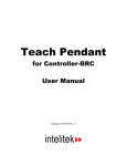
6'#%*"2'0 HQT"%QPVTQNNGT/#% 7UGTIU"/CPWCN Catalog #100121 Rev.02 Copyright © 1996, 1998 by Eshed Robotec (1982) Limited. October 1998 (PDF version) Catalog #100121 Rev.02 All rights reserved. No part of this publication may be reproduced, transmitted, transcribed, stored in a retrieval system or translated into any language in any form without the written permission of Eshed Robotec (1982) Ltd. Program listings may be entered, stored, and executed in a computer system, but they may not be reproduced for publication. Every effort has been made to make this book as complete and accurate as possible. However, no warranty of suitability, purpose, or fitness is made or implied. Eshed Robotec (1982) Ltd. is not liable or responsible to any person or entity for loss or damage in connection with or stemming from the use of the equipment and/or the information contained in this publication. Eshed Robotec (1982) Ltd. bears no responsibility for errors which may appear in this publication and retains the right to make changes to the hardware, software and manual without prior notice. Table of Contents Introduction . . . . . . . . . . . . Operation . . . . . . . . . . . . . Mounted TP . . . . . . . . . Hand-Held TP . . . . . . . . Auto/Teach Switch . . . . . . Mounted TP . . . . . . . Hand-Held TP . . . . . . TP Transition . . . . . . Manual Keyboard Control Dead Man Button . . . . . . Emergency Button . . . . . . Keypad Functions . . . . . . . . Display Panel . . . . . . . . . . Messages . . . . . . . . . . Commands . . . . . . . . . Status Report . . . . . . . . Examples . . . . . . . . TP Messages . . . . . . . . . . . . . . . . . . . . . . . . . . . . . . . . . . . . . . . . . . . . . . . . . . . . . . . . . . . . . . . . . . . . . . . . . . . . . . . . . . . . . . . . . . . . . . . . . . . . . . . . . . . . . . . . . . . . . . . . . . . . . . . . . . . . . . . . . . . . . . . . . . . . . . . . . . . . . . . . . . . . . . . . . . . . . . . . . . . . . . . . . . . . . . . . . . . . . . . . . . . . . . . . . . . . . . . . . . . . . . . . . . . . . . . . . . . . . . . . . . . . . . . . . . . . . . . . . . . . . . . . . . . . . . . . . . . . . . . . 1 1 1 1 2 2 2 3 3 3 3 4 10 10 10 10 11 12 Introduction The teach pendant for Controller-AC is a sophisticated portable terminal for operating and controlling the axes connected to the controller This teach pendant is equipped with an EMERGENCY STOP push button, an AUTO/TEACH selector switch, and a DEADMAN switch. The teach pendant can be either hand-held (thus disabling its ability to run programs) or mounted in a special fixture outside the robot’s working envelope (thus enabling access to running programs). To install the teach pendant, follow the installation instructions for the teach pendant in the Controller-AC User’s Manual. Operation Make sure the teach pendant is properly connected to the controller before you power on the system. The teach pendant can be either hand-held or mounted in a special fixture. The operation of the teach pendant will vary according to the manner in which it is held. The Auto/Teach switch on the teach pendant also affects the operation of the teach pendant, as indicated throughout this chapter. The Dead Man button and the Emergency button ensure operator safety. Mounted TP When the teach pendant is mounted in its special fixture, two magnetic switches are activated by means of magnetic strips on the fixture, thereby allowing programs to be run from the mounted TP. Mounting the TP ensures that the operator is safely out of the robot’s working envelope when program execution begins. The Auto/Teach switch must be in the Teach position to enable the mounted TP full control of the axes. Hand-Held TP When the teach pendant is hand-held, the Dead Man button must remain depressed at all times for TP operation. Programs cannot be executed from a hand-held TP. These restrictions are for safety reasons. The Auto/Teach switch must be in the Teach position to enable the hand-held TP full control of the axes. In addition, the Dead Man button must remain depressed; if this button is released, the TP is inoperative. User’s Manual 9810 -1- Teach Pendant for Controller-AC Auto/Teach Switch Mounted TP When the TP is mounted, the Auto/Teach switch affects control functions and system operation in the following ways: • When the switch is in the Teach position, the TP has full control of the axes, and programs can be run from the mounted TP. Commands which can cause axis movement (such as CON, MOVE, RUN) cannot be entered from the keyboard. All other ACL commands (such as COFF, DIR, STAT, and EDIT) remain available when the TP is in the Teach mode. • When the switch is in the Auto position, the TP is disabled, and the keyboard has full control of the axes. • When the switch is moved from Auto to Teach, running programs continue execution. Control is transferred to the TP. • When the switch is moved from Teach to Auto, running programs continue execution. Control is transfered to the keyboard, but only after the command AUTO is entered from the keyboard. Hand-Held TP When the TP is hand-held, the Auto/Teach switch affects control functions and system operation in the following ways: • When the switch is in the Teach position, the TP has full control of the axes, provided the Dead Man button is depressed. However, programs cannot be run from the hand-held TP. Commands which can cause axis movement (such as CON, MOVE, RUN) cannot be entered from the keyboard. All other commands (such as COFF, DIR, STAT, and EDIT) remain available when the TP is in the Teach mode. • When the switch is in the Auto position, the TP is disabled, and the keyboard has full control of the axes. • When the switch is moved from Auto to Teach, all running programs are aborted. • When the switch is moved from Teach to Auto, control is transfered to the keyboard, but only after the command AUTO is entered from the keyboard. TP Transition If the TP is put into or removed from the mount while the switch is in the Auto position, system operation is not affected. Teach Pendant for Controller-AC -2- User’s Manual 9810 If the TP is removed from the mount while the switch is in the Teach position, running programs are aborted. If the Dead Man button is released, or not properly depressed, during the removal of the TP from the mount, all axes will be stopped and the TP will be inoperative. If the TP is put into the mount while the switch is in the Teach position, system operation is not affected. Once the TP is in the mount, programs can be run from the TP. Manual Keyboard Control The <Alt>+M or ~ command for switching to Manual Keyboard control is available only when the TP is in the Auto mode. If the Auto/Teach switch is moved to the Teach position when Manual Keyboard mode is active, operation from the keyboard is aborted. If the switch is then moved back to the Auto position, and the command AUTO is entered in order to return control to the PC, the keyboard is reset to DIRECT mode, but not Manual mode. Dead Man Button The Dead Man button is an elongated switch on the left side of the TP, as shown in the diagram here. When the hand-held TP is in the Teach mode, this button must remain depressed at all times to enable control the axes from the TP. If the Dead Man button is released when the hand-held TP is in the Teach mode, all axes will be stopped and most of the keys on the TP will be inoperative. While the Dead Man button is released, the numerical, Record and Select Axis keys can be used for recording positions and changing the Direct Teach movement mode. Emergency Button The emergency button is the red mushroom button on the face of the TP, and functions the same as the emergency button on the controller. The emergency button can be activated regardless of the TP’s location (mounted or hand-held) or status (Teach or Auto mode). Press the button to activate; pull it out to release. When the button is pressed, the system goes into the Emergency state. To cancel the Emergency state from the TP, release the emergency botton (if it has been pressed), and press the CONTROL ON/OFF key. User’s Manual 9810 -3- Teach Pendant for Controller-AC Keypad Functions The various functions of the teach pendant are described in this section. Many of the command keys on the teach pendant are ACL commands; these commands are described fully in the ACL Reference Guide for Controller-AC. The teach pendant’s keypad has 25 color-coded keys. Most of the keys are multi-functional; for example, some keys include both an axis drive command and a numeric function. The controller recognizes the keys from the order in which they are pressed. Thus, the numeric function will be active only if a function such as SPEED, RUN, or MOVE has been keyed in first; otherwise, the axis drive command will be active. TP commands can be executed only when the TP is in the Teach mode and either the Dead Man button is depressed or the TP is mounted. The program execution command RUN is available only when the TP is mounted. Following are descriptions of the teach pendant’s keys and instructions for activating them. Bulleted items indicate the different functions of multi-functional keys. ENTER / EXECUTE • Accepts and/or executes the command which has been entered. • Starts execution of a program. JOINTS / XYZ / TOOL • Teach Pendant for Controller-AC Selects the coordinate system for command execution. Successively press for Joints, Cartesian (XYZ), Tool, and again for Joints, and so on. Depending on the active coordinate system: Manual movements of the axes are executed according to Joint, XYZ or Tool coordinates. The TP’s Record Position command records positions by executing HERE and HERER (in Joint mode), HEREC and HERERC (in XYZ mode) or HEREC and HERERT (in Tool mode). -4- User’s Manual 9810 CLR / GROUP SELECT • Clears a partially entered command. Note that this is not the same as the ACL command CLR. • Enables TP control of peripheral axes (group B), or an indenpendent axis (group C), or an electric servo gripper (group G). By default, the selected group is the robot (group A). Successively press for group A, group G (gripper), group B, group C, and again for group A, and so on. If a group is not configured, it will not be displayed. If the robot is equipped with a gripper which has an AC servo motor and resolver, the gripper will be treated as a distinct axis control group, G. If group C is displayed, enter the axis number on the numerical keys. Then press Enter. When alternating among control groups, group A will remain in the coordinate system (Joint, XYZ or Tool) in which it was last active. • In Joint mode, moves the selected axis in positive direction. • In XYZ and Tool modes, moves the TCP (tool center point) in positive direction. • If group G is selected, opens the gripper. In all of the above, movement will continue as long as the + key is depressed, or until the axis limit is reached. • This key is also used to confirm the DELETE command. • In Joint mode, moves the selected axis in negative direction. • In XYZ and Tool modes, moves the TCP (tool center point) in negative direction. • If group G is selected, closes the gripper. In all of the above, movement will continue as long as the – key is depressed, or until the axis limit is reached. + – 0 / SELECT AXIS User’s Manual 9810 • Numerical key 0. • Changes the Direct Teach movement mode. Press to change to Free Axes, Fixed Pitch or Fixed Pitch and Z mode. -5- Teach Pendant for Controller-AC 1 / AXIS 1 / X • Numerical key 1. • Axis 1 in Joint mode. • Axis X in XYZ and Tool modes. 2 / AXIS 2 / Y • Numerical key 2. • Axis 2 in Joint mode. • Axis Y in XYZ and Tool modes. 3 / AXIS 3 / Z • Numerical key 3. • Axis 3 in Joint mode. • Axis Z in XYZ and Tool modes. 4 / AXIS 4 • Numerical key 4. • Axis 4 in Joint mode. • Pitch Axis in XYZ and Tool modes. 5 / AXIS 5 • Numerical key 5. • Axis 5 in Joint mode. • Roll Axis in XYZ and Tool modes. 6 / AXIS 6 • Numerical key 6. • Axis 6 in Joint mode (only if axis installed and configured.) 7 / AXIS 7 • Numerical key 7. • Axis 7 in Joint mode (only if axis installed and configured.) 8 / AXIS 8 Teach Pendant for Controller-AC • Numerical key 8. • Axis 8 in Joint mode (only if axis installed and configured.) -6- User’s Manual 9810 9 / AXIS 9 • Numerical key 9. • Axis 9 cannot be installed or configured in Controller-AC. CONTROL ON/OFF Enables and disables control of the selected group, or all groups. • If pressed once, toggles between CON and COFF for the selected group. • If pressed twice, changes CON and COFF for all axis control groups. If at least one group is in CON mode, COFF is applied to all groups. If all groups are in COFF mode, CON is applied to all groups. The action to be performed (e.g., COFF GROUP B, CON ALL GROUPS) will be displayed. Press Enter to accept. Note that selecting an axis from the TP (axis number keys) automatically enables control of the group to which the axis belongs. If the gripper axis is selected, GRIPPER is displayed and the CON/COFF toggle applies to the gripper only. RECORD POSITION This command both defines and records a position. Only numerical position names, of up to five digits, can be entered from the TP. The position is defined for the currently active group, and receives the current values of the axes in that group. The position coordinates are recorded in the currently active coordinate system. Depending on the active coordinate system, Record Position records absolute and relative positions, as follows: • HERE and HERER in Joint mode. • HEREC and HEREC in XYZ mode. • HEREC and HERERT in Tool mode. Press Record Position. (Press once to record an absolute position; press twice to record a relative position.) Then press up to five digits for the position name, followed by Enter. If you move the axes and again press Enter, the TP will repeat the Record Position command and automatically increment the position name by one number. (Any key other than Enter will cancel the Record Position command and allow you to enter another command.) If you use a position name which has already been defined, the new coordinates will overwrite the existing ones. This command is also used to record positions in a vector. The vector must first be attached (ATTACH) to the TP. User’s Manual 9810 -7- Teach Pendant for Controller-AC INSERT / DELETE This command is used to add and remove positions in a vector. The vector must first be attached (ATTACH) to the TP. INSERT records a position in a vector, and shifts all previously recorded positions one place up in the vector. DELETE removes a position from a vector, and shifts all higher positions one place down. INSERT and DELETE are available only on position vectors which have been defined with the prefix &. • If pressed once, INSERT is displayed. Use the numerical keys to enter the number of the position (the vector index) to be inserted. Press Enter to execute the command. • If pressed twice, DELETE is displayed. Use the numerical keys to enter the number of the position (the vector index) to be deleted. Press Enter. The display shows “ ARE YOU SURE?” Press + for yes, and then press Enter again. SPEED(%) / SPEEDL (%) Sets the speed of manual axis movement, as a percentage of maximum speed. • If in Joint mode, sets the percentage of maximum joint speed. SPEED is displayed. • If in XYZ or Tool mode, sets the percentage of maximum linear speed. SPEEDL is displayed. Press SPEED(%)/SPEEDL(%). The current speed is displayed. Press Enter to accept the displayed default speed. Or use the numerical keys to enter a different speed, and press Enter. OPEN / CLOSE Opens and closes the gripper. This command functions on both electric and pneumatic grippers. MOVE / MOVEL Moves the axes to a target position. MOVEL applies only to robot (group A) axes. Teach Pendant for Controller-AC • If in Joint mode, movement is by joints (MOVE) • If in XYZ or Tool mode, robot movement is linear (MOVEL) Press MOVE/MOVEL. Then use the numerical keys to enter the position number. Press and hold the Execute key. Continue holding down the Execute key until the axes reach the target position. If the Execute key is released, the movement is stopped immediately, and the command is aborted. -8- User’s Manual 9810 • The command MOVE 0 moves the axes of the currently active group (A or B only) to their home position. The TP display panel will show MOVE 0 for group A, and MOVE 00 for group B. • When group G is active, pressing this key activates the JAW command for the gripper. Use the numerical keys to enter a value for the percentage of the gripper opening, and press Enter. SPLINE / MOVEC Moves the axes to a target position. MOVEC applies only to robot (group A) axes. SPLINE applies only to multi-axis devices in group A or group B axes. • If pressed once, a SPLINE movement will be executed. • If pressed twice, a MOVEC movement will be executed. Use the numerical keys to enter the first position number, and press Enter. Use the numerical keys to enter the second position number. Then press and hold Execute. Continue pressing the Execute key until the axes reach the target position. If the Execute key is released, the movement is stopped immediately, and the command is aborted. RUN Executes a program. Available only when the TP is mounted. Press Run. Then press the program’s identity number on the numerical keys. The program name will be displayed in brackets. Then press Enter. The controller automatically assigns an ID number to each user program. The ACL command DIR lists the programs and their assigned (IDENTITY) number. • The command RUN 0 homes the robot axes (ACL command HOME). • The command RUN 999 executes a system test (ACL command TEST). SINGLE STEP This command is not currently available. ABORT Aborts execution of all running programs. Stops the robot and all peripheral axes. User’s Manual 9810 -9- Teach Pendant for Controller-AC Display Panel The teach pendant has a four-line liquid crystal display panel. Each line displays a specific type of message or text. Messages When the TP is in either the Teach Mode or Auto mode, line 1 displays system and error messages. The current display is erased when a new message appears. When the TP is in the Auto mode, lines 2, 3 and 4 will display: TP IN AUTO MODE TEACH MODE WILL ABORT ALL PROGRAMS A list and brief descriptions of all TP messages appears at the end of this chapter. Commands When the TP is in the Teach mode, lines 2 and 3 display commands. Line 2 displays the last command entered. Subsequent commands are scrolled into Line 2. Line 3 displays the command currently being entered, and serves as a user interface. • The command SPEED/SPEEDL will display the current value, allowing you to accept or change. • The commands SPLINE/MOVEC, INSERT/DELETE, RECORD POSITION and MOVE/MOVEL will display the name of the currrently attached position vector, if it exists, and the active control group. Status Report When the TP is in the Teach mode, line 4 displays the current status of the axes, in the following format: group:g AX: xx cccccc When the group (or a specific group C axis) is enabled (CON), the text in the display is normal (black on white). When the group (or a specific group C axis) is disabled (COFF), the text in the display is inversed (white on black). g is the currently selected axis control group (if exists): A: control group A G: gripper B: control group B C: control group C Teach Pendant for Controller-AC -10- User’s Manual 9810 xx is the currently active joint or axis in the active group: 1-12: joint X : X axis Y : Y axis Z : Z axis P : Pitch axis R : Roll axis cccccc is the currently active coordinate system: Joint XYZ Examples GROUP:C AX:7 JOINTS Group C, Axis 7 is active, Joint mode, in COFF state. GROUP:A AX:P XYZ Group A, Pitch axis is active, XYZ mode, in CON state. User’s Manual 9810 -11- Teach Pendant for Controller-AC TP Messages The following is an alphabetical listing of the system messages which may appear on line 1 of the teach pendant during manual operation and program execution. The explanation of each message includes the system’s ID number for the message and the text of the comparable message which appears on the computer screen. Refer to the ACL Reference Guide for Controller-AC for complete descriptions of these messages and full instructions for correcting situations which cause the display of an error message. ALL PROGRAMS ABORTED (205) All programs aborted. The TP Abort key has been pressed or the mounted TP has been removed from the fixture when in the Teach mode. ARITHMETIC OVERFLOW (302) Arithmetic overflow (or division by zero) The result of a mathematical operation is out or range (or invalid). AXIS DISABLED (304) Axis disabled. Servo control of the arm has been disabled (COFF). BAD AXIS (310) Invalid axis. The axis is not in the group specified by the command, or the axis is not configured. BAD GROUP (321) MOVES/SPLINE not allowed for a single axis group. The command (MOVES) cannot be executed on a single axis group. BAD POS n (312) Invalid position coordinate values. You attempted to use an invalid position. BAD XYZ POSITION (317) Invalid Cartesian position pos. The position could not be recorded or reached because its XYZ coordinates are out of the XYZ envelope. CONTROL DISABLED (72) CONTROL DISABLED. Motors have been disconnected from servo control. Teach Pendant for Controller-AC -12- User’s Manual 9810 CONTROL ENABLED (73) CONTROL ENABLED. Motors are now under servo control. EMERGENCY (148) To perform action - release emergency button. The emergency switch has been pressed. HANDLE PUSHED! (167) Pressure was applied on handle before switch activation (168) or payload is too heavy for Direct Teach When using the Direct Teach handles, you must first grasp the handle with the Dead Man switch. Only then can you begin to apply pressure in order to move the robot. HOME FAIL n (51) *** HOME FAILURE AXIS n. The homing procedure failed for the specified axis. HOME NOT DONE (301) Group/axis has not been homed. You attempted to move the arm to a recorded positions, or to record a position, before homing was performed on the group or axis. HOMING (31) WAIT !! homing... Homing complete (32) Homing complete IMPACT AX n (53) *** IMPACT PROTECTION axis n The controller has detected a position error which is too large. The system aborted all movements of that axis group, and disabled all axes of that group. INCOMPATIBLE POS (315) Incompatible positions. The position or positions you attempted to manipulate are dedicated to different axis control groups. Index or data error (36) Invalid index or value. The command has an incorrect index value. INDEX RANGE (309) Index value - out of range. The value of the index is out of range. User’s Manual 9810 -13- Teach Pendant for Controller-AC INVALID PROGRAM (306) Invalid program. Faulty syntax or logic in the program. LIMIT AX n (33) *** UPPER LIMIT AXIS n (34) *** LOWER LIMIT AXIS n Axis encoder has reached either its maximum or minimum allowed value. MOTORS OFF (319) Motor power switch is off. The controller’s Motor is turned off. NO GRIPPER (316) No gripper configuration. The command cannot be executed because a gripper has not been configured. NO FREE SPACE (159) No free space to insert point All positions in the vector have been allocated; no memory available. No hard Homing (40) Cannot hard home axis n. The specified axis has not been configured for hard homing. NOT ABS POINT (322) Position must have Absolute Joint coordinates. The command (MOVES) can only be executed on positions with absolute JOINT values. NOT XYZ SPACE (320) Robot is not in XYZ space. The robot is at a position at which the XYZ coordinate system is not supported. POINT LOOP (311) Relative chain loops or exceeds 32 positions. An error in the linking or recording of the positions in a chain of relative positions. POS NOT DEF/ARRAY (145) Position is not defined or is not a vector. The position has not been defined, or this is not the name of a position vector. Teach Pendant for Controller-AC -14- User’s Manual 9810 POS NOT FOUND (110)Position undefined, not recorded, or for other group. The position you attempted to use has not been defined, or has not been recorded, or has been defined for another axis control group. POS NOT RECORDED (74) (303) No coordinate values for position. The position coordinates have not been recorded or set. POS TYPE n (313) Incompatible position type pos. You have attempted to use a position whose type is incompatible with the command. RANGE AX n (54) *** OUT OF RANGE axis n. An attempt was made to record a position (HERE, HEREC, etc. ) while the robot arm was out of its working envelope. SERVO ERROR (212) Error must be reset. The controller’s SERVO ON/OFF switch is in the OFF position; therefore, motors cannot be enabled. SERVO SWITCH IS OFF (201) (319) SERVO switch is off. The controller’s Servo is turned off. TOO DEEP NESTING (305) Nesting too deep. Too many GOSUB subroutines are nested within one another. TOO FAST AX n. (99) *** SPEED TOO FAST axis n. The controller has detected a movement which is too fast. use HERE or HEREC (160) INSERT position is empty, use HERE or HEREC You attempted to insert a position which does not have any coordinate values. User’s Manual 9810 -15- Teach Pendant for Controller-AC