1
PrecisionAire Software, Hardware
and Controller
USER’S MANUAL
TOL-O-MATIC, INC
Excellence in Motion®
3604-4104_03.0
© Copyright 2004
Tol-O-Matic Incorporated. All rights reserved.
PrecisionAire and Tol-O-Matic are registered trademarks of Tol-O-Matic Incorporated. All other products or brand names are trademarks of their
respective holders.
DMS 01/04
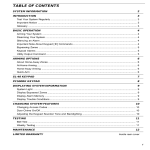
Table of Contents
Chapter 1
1.1
1.2
1.3
1.4
1.5
Chapter 2
2.1
2.2
2.3
2.4
Chapter 3
3.1
3.2
3.3
Chapter 4
4.1
4.2
Chapter 5
5.1
5.2
5.3
5.4
5.5
5.6
5.7
5.8
5.9
5.10
Chapter 6
6.1
6.2
6.3
6.4
6.5
Introduction
PrecisionAire Overview..........................................................
Features...................................................................................
Controller/Drive Specifications............................................
Actuator Specifications ..........................................................
Agency Approvals...................................................................
1-1
1-3
1-4
1-5
1-5
Safety
Potential Hazards ...................................................................
Voltage Potentials...................................................................
Installer Responsibilities .......................................................
Safety Guidelines....................................................................
2-1
2-1
2-1
2-2
Unpacking, Inspection, and Storage
Unpacking the Controller/Drive........................................... 3-1
Inspection Procedure ............................................................ 3-1
Storage .................................................................................... 3-1
Physical Mounting
Actuator .................................................................................. 4-1
Controller/Drive..................................................................... 4-1
Hardware Setup
Setting up the Air System ........................................................5-1
Valve Connections ...................................................................5-1
Horizontal Applications ..........................................................5-5
Vertical Applications................................................................5-5
Brake Wiring .............................................................................5-5
Encoder Wiring.........................................................................5-6
115/230 Vac Power Wiring .......................................................5-6
Input Wiring .............................................................................5-7
Output Wiring...........................................................................5-9
Cushions and Shock Absorbers ............................................5-10
Software Setup and Programming
General Considerations...........................................................6-1
PC Hardware Requirements....................................................6-2
PC Software Installation ..........................................................6-2
System Setup ............................................................................6-3
Set-up Parameter Definitions .................................................6-4
Actuator parameters.................................................................6-4
Default motion parameters .....................................................6-5
Positioning................................................................................6-5
Servo parameter gains..............................................................6-6
Encoder Monitoring .................................................................6-6
i
C O N T E N T S C O N T E N T S
Chapter 6
6.6
6.7
6.8
6.9
ii
Software Setup and Programming (continued)
Software limits..........................................................................6-7
Units ..........................................................................................6-7
Com Ports..................................................................................6-8
Password Protection .................................................................6-8
Set up and Programming from Windows-based ...................6-9
PC software
A. Toolbar descriptions .............................................................6-9
B. Programming.....................................................................6-10
Move Options.................................................................6-10
Move .......................................................................6-10
Move & output .......................................................6-11
Wait time ................................................................6-13
Seek home ..............................................................6-13
I/O Options ....................................................................6-14
Feed to sensor ........................................................6-14
Wait input...............................................................6-14
Pause on input .......................................................6-15
Set output...............................................................6-16
Looping Options............................................................6-17
Repeat.....................................................................6-17
End Repeat .............................................................6-17
Goto ........................................................................6-18
End subroutine ......................................................6-19
Setting Options ..............................................................6-19
Define position ......................................................6-19
Set variable.............................................................6-19
In-position band....................................................6-20
Operation mode ....................................................6-20
Servo settings .........................................................6-21
Software limits .......................................................6-22
Interface Option ............................................................6-22
Prompt....................................................................6-22
Comment Option ..........................................................6-23
C. View/edit variable ..............................................................6-24
D. Terminal Screen .................................................................6-24
Setup and Programming from Keypad & LCD.....................6-25
Programming Examples ........................................................6-29
Example Applications............................................................6-34
C O N T E N T S
Chapter 7
7.1
7.2
7.3
Chapter 8
8.1
8.2
8.3
8.4
8.5
8.6
8.6
Chapter 9
9.1
9.2
Appendix
Tuning
Data Acquisition.......................................................................7-1
Tuning .......................................................................................7-3
A. Proportional gain (KP).........................................................7-4
B. Integral gain (KI) ..................................................................7-4
C. Speed gain (KV) ....................................................................7-4
D. Deceleration current constant (KT) ....................................7-4
E. Tuning Tips ...........................................................................7-5
Tuning Examples......................................................................7-5
Trouble Shooting
Display and Diagnostics..........................................................8-1
Fault (Fault LED is ON)............................................................8-1
Power LED is OFF after Power ON..........................................8-3
No Communication with Controller ......................................8-4
No Motion Occurred................................................................8-5
No LCD Display........................................................................8-8
Carriage Runaway ....................................................................8-8
Technical Information
Control block diagram.............................................................9-1
LCD screens..............................................................................9-2
A.Warranty Information
Warranty Information .............................................................A-1
B. Binary Code .......................................................................B-1
C.Technical Reference — Communication Protocol
Introduction.............................................................................C-1
What is a programming command..................................C-1
What is a terminal command...........................................C-1
Programming commands.......................................................C-3
AD: After distance..............................................................C-3
AU: Auto Execution ...........................................................C-3
DP: Define encoder position ............................................C-3
EN: End of program ..........................................................C-4
FI: If input goto..................................................................C-4
FL: Feed to length/cut to length.......................................C-5
FP: Feed to position ..........................................................C-5
FS: Feed to sensor..............................................................C-5
GT: Goto .............................................................................C-6
HM: Carriage home...........................................................C-7
MG: Display message on LCD & read data......................C-7
iii
C O N T E N T S C O N T E N T S
Technical Reference
Communication Protocol (continued)
NO: Comment, no operation ...........................................C-7
OM: Set operation mode ..................................................C-8
PI: Pause program on input..............................................C-8
PR: Set position repeatability ...........................................C-8
RE: Repeat end/return ......................................................C-9
RP: Repeat loop .................................................................C-9
SC: Set constant to variable ..............................................C-9
SL: Configure software limits .........................................C-10
SP: Set speed ....................................................................C-10
SS: Set servo settings .......................................................C-10
SV: Store internal value to variable ................................C-11
TA: Set acceleration time ................................................C-11
TD: Set deceleration time ...............................................C-11
WI: Wait for input ............................................................C-12
WT: Wait time...................................................................C-12
Terminal Commands ............................................................C-13
a: Set reverse position limit ............................................C-13
A: Set forward position limit...........................................C-13
bV: Set backward valve ON .............................................C-13
B: Configure position compensation & program
auto execution .................................................................C-13
c: Display keypad password ...........................................C-13
CO: Set and overwrite keypad interface password .......C-14
Cc: Clear position compensation table .........................C-14
Cl: Load position compensation table to RAM.............C-14
Cs: Save position compensation table to EEPROM......C-14
db: Display actuator bore size ........................................C-14
dB: Display position compensation & auto
execution flag ..................................................................C-15
dc: Display current command........................................C-15
dD: Display in-position valve status..............................C-15
dE: Display encoder monitoring....................................C-15
de: Display position error ...............................................C-15
df: Display current feedback ..........................................C-15
dF: Display fault ..............................................................C-16
dh: Display in-position holding torque.........................C-16
di: Display input/output status......................................C-16
dI: Display integral gain KI .............................................C-16
dk: Display actuator stroke length .................................C-17
dl: Display load/weight...................................................C-17
dL: Display executing program & line number.............C-17
dm: Display software limits ............................................C-17
iv
C O N T E N T S
Technical Reference
Communication Protocol (continued)
dM: Display selected variable name & data ..................C-17
do: Display overshoot .....................................................C-18
dO: Display actuator orientation ...................................C-18
dP: Display proportional gain KP...................................C-18
dp: Display program running status..............................C-18
dq: Display data collection sampling rate.....................C-18
dQ: Display controller fault history ...............................C-18
dr: Display data collection type .....................................C-19
dR: Display program execution trace status .................C-19
ds: Display commanded speed ......................................C-19
dS: Display actual maximum speed...............................C-20
dt: Display deceleration torque constant KT ................C-20
dU: Display user unit ......................................................C-20
dv: Display actual speed .................................................C-20
dV: Display velocity gain KV ...........................................C-20
dw: Display position repeatability .................................C-21
dx: Display program pause by inputs status .................C-21
dz: Display firmware revision information ...................C-21
D: Set in-position valve output ......................................C-21
e: Jog carriage...................................................................C-22
eQ: Clear fault history .....................................................C-22
E: Define encoder position .............................................C-22
fV: Set forward valve ON .................................................C-22
FS: Feed to sensor............................................................C-22
g: Go, begin move ............................................................C-23
G: Set deceleration torque constant KT.........................C-23
h: Carriage home .............................................................C-23
H: Set in-position holding torque ..................................C-23
I: Set integral gain KI .......................................................C-24
i: Encoder monitoring.....................................................C-24
j: Load program from EEPROM to RAM ........................C-24
J: Save program to EEPROM ...........................................C-24
k: Set actuator stroke length ...........................................C-24
K: Set proportional gain KP ............................................C-24
l: List program..................................................................C-24
L: Download program / configure software limit .........C-25
m: Select variable ............................................................C-25
M: Set variable name or data..........................................C-25
n: Set output ....................................................................C-25
N: Set load/weight...........................................................C-25
o: Set actuator bore size..................................................C-26
O: Set actuator orientation .............................................C-26
v
C O N T E N T S C O N T E N T S
Technical Reference
Communication Protocol (continued)
p: Display position information.....................................C-26
P: Set commanded position ...........................................C-26
q: Quit motion program..................................................C-26
Q: Controller soft reset....................................................C-26
r: Run motion program...................................................C-27
R: Set data collection type ..............................................C-27
s: Activate servo loop ......................................................C-27
S: Set data collection sampling rate ...............................C-27
t: Display motion profile time ........................................C-27
TA: Set acceleration time ................................................C-28
TD: Set deceleration time ...............................................C-28
TO: Set profile timeout....................................................C-28
TR: Set program execution trace mode .........................C-28
u: Upload collected data .................................................C-28
uT: Upload tuning speed data ........................................C-28
U: Set user unit ................................................................C-29
v: Set maximum speed limit ...........................................C-29
V: Set commanded speed ...............................................C-29
w: Set speed following error limit ..................................C-29
W: Set position repeatability ..........................................C-29
x: Stop motion .................................................................C-29
X: Stop servo loop............................................................C-30
y: Save controller settings ...............................................C-30
yV: Save variables to EEPROM........................................C-30
Y: Set velocity gain KV .....................................................C-30
z: Halt program execution ..............................................C-30
zx: Halt program execution and stop motion ...............C-31
Z: Resume program execution .......................................C-31
^C: End program download ...........................................C-31
vi
C O N T E N T S
List of figures:
1.1
4.1
4.2
5.1
5.2
5.3
5.4
5.5
5.6
5.7
5.8
5.9
5.10
6.0
6.1
6.2
6.3
6.4
6.5
6.6
6.7
6.8
6.9
6.10
6.11
6.12
6.13
6.14
6.15
6.16
6.17
6.18
6.19
6.20
6.21
6.22
6.23
6.24
6.25
6.26
6.27
PrecisionAire actuator.................................................................. 1-2
Tube support requirements...........................................................4-1
Controller/drive dimensions.........................................................4-2
3-way normally open valve connections......................................5-2
3-way normally closed valve connections ...................................5-3
3-position 4-way, spring centered valve connections .................5-4
Encoder to PrecisionAire controller connections........................5-6
Connect ac power to PrecisionAire controller .............................5-6
Controller input connections........................................................5-8
Tol-O-Matic form A reed switch connections..............................5-8
Tol-O-Matic form C reed switch connections..............................5-8
Tol-O-Matic Hall-effect switch connections ................................5-9
Controller output connections .....................................................5-9
Repeatability Tolerances................................................................6-1
Software set-up screen...................................................................6-4
Forward and reverse position limits .............................................6-7
PrecisionAire software - Programming options.........................6-10
Move command............................................................................6-11
Teach command ...........................................................................6-11
Move and set output command (move) .....................................6-12
Move and set output command (set output) .............................6-12
Wait time command.....................................................................6-13
Seek home command ..................................................................6-13
Feed to sensor command ............................................................6-14
Wait for single input .....................................................................6-15
Wait for multiple inputs...............................................................6-15
Pause on input command ...........................................................6-16
Setting a single output .................................................................6-16
Setting multiple outputs ..............................................................6-17
Repeat loop command.................................................................6-17
Go to line number ........................................................................6-18
Go to program number................................................................6-18
Define encoder position command............................................6-19
Set variable command .................................................................6-20
In-position band command ........................................................6-20
Operation mode command: Servo Mode...................................6-21
Operation mode command: Thrust Mode .................................6-21
Servo setting command ...............................................................6-22
Software limits command............................................................6-22
Prompt command ........................................................................6-23
Comment command....................................................................6-23
vii
C O N T E N T S C O N T E N T S
List of figures (continued):
6.28
6.29
6.30
6.31
6.32
6.33
6.34
6.35
6.36
6.37
7.1
7.2
7.3
7.4
7.5a
7.5b
7.6a
7.6b
7.6c
7.6d
7.7a
7.7b
7.7c
8.1
8.2
8.3
8.4
8.5
8.6
8.7
8.8
9.1
viii
Display and diagnostics screen ...................................................6-24
Terminal window..........................................................................6-25
Binary code of decimal value 10 for multiple I/O......................6-27
PrecisionAire keypad interface....................................................6-28
Command map of PrecisionAire LCD/Keypad interface ..........6-29
Program example using keypad interface ..................................6-31
Program example using PC software ..........................................6-33
Parts transfer program example..................................................6-34
Clamping program example........................................................6-35
Lumber cutting program example ..............................................6.37
Start Move and Data Acquisition ..................................................7-1
Position Data ..................................................................................7-1
Brake Current Data.........................................................................7-1
Command and actual speed data .................................................7-2
Parameters ......................................................................................7-3
Adjustments within the program ..................................................7-3
......................................................................................................... 7-5
......................................................................................................... 7-6
......................................................................................................... 7-6
......................................................................................................... 7-7
......................................................................................................... 7-8
......................................................................................................... 7-8
......................................................................................................... 7-8
Display & diagnostics screen.........................................................8-1
List of controller fault message, description and action plan ....8-2
Flow chart for trouble shooting with power LED off fault ..........8-3
Flow chart for checking controller communications..................8-4
Flow chart for checking valve connection using keypad ............8-5
Flow chart for checking valve connection using PC....................8-6
Flow chart for checking encoder connection using keypad .......8-7
Flow chart for checking encoder connection using PC...............8-7
PrecisionAire control-block diagram............................................9-1
Chapter 1 Introduction
1.1 PrecisionAire Overview
PrecisionAire was developed to be a low cost position control system
relative to electric motion systems, without the setup and control challenges
of traditional proportional valve pneumatic servo systems. PrecisionAire is
intended for applications not requiring positional repeatability better than
+/-0.010 inches up to a 120" stroke. Longer strokes up to the maximum
stroke length are capable of repeatability better than +/-0.025 inches.
Motion profiles are user defined by programming the move distance, the
maximum speed, acceleration time, and deceleration time. System
variables, including supply pressure, valve Cv, the load, and how well the
system is tuned, do not effect the final repeatability of the system. However,
they will influence how well the actual motion follows the theoretical
profile.
PrecisionAire significantly reduces the concerns of changing loads,
system friction, vertical operation, setup, tuning, instabilities, and long
stroke lengths typically experienced with pneumatic servo systems. The TolO-Matic patent-pending approach used in PrecisionAire accomplishes this
using the muscle of air to provide thrust and an electric current-controlled
magnetic particle brake to provide proportional braking for position control.
This approach significantly reduces the effects of directly attempting to
control a compressible fluid through proportional valves, or trying to predict
when to activate an on/off brake to achieve a desired position.
The PrecisionAire system requires pressure regulators. To minimize
overshooting past the desired position it is recommended to operate at an
air pressure no greater then 10 psi above the pressure required to achieve
the desired speed or force. Limiting the air pressure will also reduce the
brake regulation at constant speeds, which can reduce system ‘hesitations’
caused by the brake trying to overcompensate for higher air pressures.
PrecisionAire software has an easy to use Data Acquisition that can insure
the proper air pressure is selected based upon the applications loads and
speeds. In a vertical application a dual pressure system must be used. Two
separate external pressure regulators (or valves with a sub-base mounted
pressure regulator) are required to provide a dual pressure system to the
actuator. The brake end of the PrecisionAire actuator must be mounted at
the top.
The thrust limitations experienced in a traditional end-of-stroke open
loop pneumatic system are also present in PrecisionAire. These limitations
are due to constraints including differential air pressure, bore size, system
Cv, and friction in the system. These constraints will limit the maximum
speed, thrust to overcome an external force, and acceleration of a load.
1-1
1 : I N T R O D U C T I O N
Tol-O-Matic provides Tol-O-Motion Sizing and Selection software to
provide guidance regarding these constraints as they apply to specific
applications.
Tol-O-Motion Sizing and Selection software also considers duty cycle
limitations due to heat dissipation requirements of the brake. Heat
generation takes place not only during deceleration of a load, but also
during regulation at a constant speed. It is desirable to operate at a
minimum supply pressure necessary for the application. This will minimize
the heat generated by the brake, therefore, maximizing the application’s
duty cycle. There may also be a minimum speed that can be achieved with a
given air pressure, determined by the duty cycle desired. Data Acquisition
within the PrecisionAire software can help determine the minimum supply
pressure required for your loads and speeds.
The PrecisionAire system is packaged to be a completely independent
system or part of a higher level system through communications with inputs
and outputs. A system consists of an actuator with integral brake and
encoder, and a programmable controller/drive. As shown below, the
PrecisionAire system utilizes a completely enclosed, internal timing belt to
provide the linkage between the cylinder carrier, the brake, and an optical
encoder. Recommended valves are discussed in Chapter 5, however, they
are not included as part of the PrecisionAire system.
Figure 1.1 PrecisionAire actuator
The controller operates from line voltage, and therefore, does not
require additional external power supplies. Setup is quick and easy using
the Windows-based Icon programming through the RS232 serial port or
with the optional onboard keypad and LCD screen. Teach modes are
available in either mode of programming. Default servo gains are supplied
with the PrecisionAire system. Depending on loads and the desired motion
profile, a manual adjustment of these gains may be required. Data
Acquisition can help determine proper servo gain adjustments by
1-2
I N T R O D U C T I O N : 1
comparing the actual versus the commanded move profile. The controller
has internal EEPROM capable of storing up to 10 programs (each 100 lines)
that can be activated directly, on power-up, or with an input.
1.2 Features
1.
2.
3.
4.
5.
6.
7.
8.
9.
10.
11.
12.
13.
14.
15.
16.
17.
18.
19.
20.
21.
Position control.
Programmable position repeatability of +/- 0.010 in up to 120" stroke.
For longer strokes repeatability can be expected better than
+/- 0.025 in.
Repeatability independent of supply pressure, valve Cv and load
changes
Programmable user units, motion profile and holding torque.
Jog and teach functions
One RS232 serial port for optional Windows-based programming
1024 line rotary encoder for position feedback
7 General purpose optically-isolated inputs and 4 optically-isolated
outputs
Dedicated enable input, fault/error and in-position outputs
Two 24Vdc valve outputs. (250mA max. for each output)
Power ON, Fault/Error, and In-Position LED indicators.
Optional 4x20 character LCD display and an embedded keypad for easy
set-up and programming also functions as embedded HMI
64K byte EEPROM for saving up to 10 motion programs (each up to 100
command lines).
Uses standard directional air valves (NO SERVO VALVES required)
Data collection for tuning (available with Windows-based software)
Pluggable screw terminals (no breakout terminals required)
Short-circuit protection, current fault, position fault, configurable
software limits protection.
Actuator available in 1" and 11⁄2" bore sizes.
Re-circulating ball-bearing load support system provides, high direct
load capacity, high moment load capacity, and wear resistance.
Wedge design guarantees that the raceways are parallel, which ensures
a pre-load that is consistent throughout the length of the cylinder.
Compact package size (compared to electric systems)
1-3
1 : I N T R O D U C T I O N
1.3 Controller/Drive Specifications
Power
Continuous current
Peak current (1 sec)
Input Voltage (single/3 phase)
Input frequency
1-in brake (PAS10)
1.5 in brake (PAS15)
1 Amp
2 Amp
2 Amp
4 Amp
95-130 Vac (190-250Vac)
(Voltage range is switch selectable)
47-63 Hz
Serial communication port
Type
Settings
Inputs and outputs
Dedicated optically isolated input
ENABLE
Dedicated optically isolated outputs
2 valve solenoid outputs
in-position & fault outputs
General-purpose optically isolated inputs
seven inputs
General-purpose optically isolated outputs
four outputs
Encoder Feedback
Connectors
Serial
All others
Environmental
Storage temperature
Operating temperature
Humidity
Mechanical
Dimensions
Weight
1-4
RS-232
19200 baud, 8 data bits, no parity, 1 stop bit, no flow control
5-24Vdc, 15mA max
Can be configured to source or sink current
24Vdc max, 250mA max
24Vdc max, 20mA max
5-24Vdc, 15mA max
Can be configured to source or sink current
5-24Vdc, 20mA max
Can be configured to source or sink current
1024 lines, Incremental, 5Vdc, differential, A/B channels
9 pin D-sub.
Pluggable screw terminal blocks
-4F to 158F (-20C to 70C)
32F to 104F (0 to 40C)
5% to 95% non-condensing
5.8" height x 10.1" wide x 3.3" deep
8 lbs (3.7 kgs)
I N T R O D U C T I O N : 1
1.4 Actuator Specifications
Specifications:
Base Weight (incl. carrier)
Weight per inch of stroke
Maximum Stroke Length
Dead Length (2 x “A”)
Maximum Load
at Maximum Speed
Positional Repeatability
Operating Temperature
Recommended Belt Tension
Maximum Air Pressure
Maximum Load Fz
Fy
Maximum Bending Moments
Mx
My
Mz
Pulley Pitch DIA.
Belt Width
Length of Air Cushion Spear
Brake Coil Resistance
PAS10 (1 inch bore)
14.82 lbs.
0.308 lbs.
18'
15.7"
75 lbs. @ max. speed
of 100 in./sec.
± 0.010" up to 120" strk
32°F to 104°F
60 lbs.
100 PSI
591 lbs.
341 lbs.
(6.72 kgs.)
(0.0055 kgs./mm)
(5.5 m)
(399 mm)
(34 kgs. @ max. speed)
(of 2.54 m/sec.)
(± 0.25 mm up to 2540mm strk)
(0° to 40°C)
(267 N)
(6.89 Bar)
(268 kgs.)
(155 kgs.)
PAS15 (1.5 inch bore)
23 lbs.
0.504 lbs.
16' 5"
22.64"
150 lbs. @ max. speed
of 100 in./sec.
± 0.010" up to 120"strk
32°F to 104°F
122 lbs.
100 PSI
1,454 lbs.
840 lbs.
(10.43 kgs.)
(0.01114 kgs./mm)
(5.0 m)
(575.1 mm)
(68 kgs. @ max. speed)
(of 2.54 m/sec.)
(± 0.25 mm up to 2540mm strk)
(0° to 40°C)
(543 N)
(6.89 Bar)
(660 kgs.)
(381 kgs.)
250 in.-lbs.
269 in.-lbs.
156 in.-lbs.
1.88”
0.75”
1.0"
8 ohms
(28.25 N-m)
(30.39 N-m)
(17.63 N-m)
(47.7 mm)
(19 mm)
(25.4 mm)
8 ohms
859 in.-lbs.
1033 in.-lbs.
596 in.-lbs.
2.506”
1.00”
1.7"
4 ohms
(97.06 N-m)
(116.72 N-m)
(67.34 N-m)
(63.7 mm)
(25 mm)
(43.1 mm)
4 ohms
metric equiv.
metric equiv.
1.5 Agency Approvals
Refer to approval agency marks on the controller/drive or
contact
Tol-O-Matic for latest information on agency approvals.
Before you begin…
To reduce risk of injury and equipment damage and eliminate
wasted time and effort, please read this manual in its entirety before
attempting to install or operate the controller.
1-5
1 : I N T R O D U C T I O N
NOTES:
1-6
Chapter 2 Safety
2.1 Potential Hazards
The equipment described in this manual is intended for use in
industrial control/drive systems. This equipment can endanger life
through moving machinery and high voltage, therefore it is essential
that guards for both electrical and mechanical parts be in place.
Hazards which can be encountered in the use of this equipment
include:
• Electrical shock
• Electrical fire
• Mechanical
• Stored energy
These hazards must be controlled by suitable machine design,
using the safety guidelines which follow.
2.2 Voltage Potentials
Voltage potentials for the internal drive circuitry vary from 325
volts above to 325 volts below earth ground for a 230 volt input.
Voltages can reach 88 Vdc within the controller. All circuits,
including the connections on the front panel, should be considered
“hot” when power is connected.
2.3 Installer Responsibilities
As the user or person installing the controller/drive, you are
responsible for determining the suitability of the product for the
intended application. Tol-O-Matic is neither responsible nor liable
for indirect or consequential damage resulting from the use of this
product.
A qualified person is someone who is familiar with all safety
codes and established safety practices pertaining to the installation,
operation and maintenance of this equipment and the hazards
involved. For more detailed definition, refer to IEC 364.
It is recommended that anyone who operates or maintains
electrical or mechanical equipment should have a basic knowledge
of First Aid as a minimum, they should know where the First Aid kit
is kept and the identity of the official First Aid personnel.
These safety notes do not represent a complete list of the steps
necessary to ensure safe operation of the equipment. For further
information, please contact the nearest Tol-O-Matic distributor.
2-1
2 : S A F E T Y
2.4 Safety Guidelines
Electrical shock and fire hazard can be avoided by using normal
installation procedures for electrical power equipment in an
industrial environment. Installation must be undertaken by suitably
qualified personnel.
Mechanical hazards are associated with potential uncontrolled
movement of the actuator. If this poses a risk in the machine,
appropriate precautions must be made to disconnect the air source
when personnel have access to moving parts of the machine. Note
also that the brake must be securely mounted at all times.
Storage energy hazards are both electrical and mechanical.
1. Electrical hazards can be avoided by disconnecting the
controller/drive from its power source and waiting for at least 1
minute prior to removing protective covers or touching any
connections.
2. Mechanical hazards require a risk analysis on the effects of
stored mechanical energy when the machine is running at speed, as
well as the potential for the disconnection of the brake while air
source is applied.
The following points should be observed for the safety of
personnel:
• Only qualified personnel familiar with the equipment are
permitted to install, operate and maintain the device.
• System document must be available and observed at all times.
• All non-qualified personnel should maintain a safe distance
from the equipment.
• The system must be installed in accordance with local
regulations.
• The equipment is intended for permanent connection to a main
power input. It is NOT intended for use with a portable power
input.
• DO NOT power up the unit without all guards and covers in
place.
• DO NOT operate the unit without connecting the brake
conductors to the appropriate terminals on the controller/drive.
• Always remove power before making or removing any
connection on the unit. Failure to observe this condition could
result in injury or damage to equipment.
• DO NOT remove cover from unit while in operation.
2-2
S A F E T Y : 2
•
•
•
DO NOT make any connections to the internal circuitry.
Connections on the side panels are the only points where users
should make connections.
Be careful of the line voltage input and brake output terminals.
High voltage is present when power is applied to the
controller/drive.
DO NOT use the enable input as a safety shutdown. Always
remove power to a controller/drive before maintaining or
repairing the unit.
2-3
2 : S A F E T Y
NOTES:
2-4
Chapter 3 Unpacking, Inspection and Storage
3.1 Unpacking the Controller/Drive
Remove the PrecisionAire™ controller from the shipping carton.
Retain the shipping materials for storage or in case the unit needs to
be returned. Check contents against the packing list. Model, part
number and related information appear on a label on the bottom of
the controller/drive.
3.2 Inspection Procedure
To protect your investment and ensure applicable warranty
rights, Tol-O-Matic recommends the unit be carefully inspected for
any signs of physical damage. If any damage is detected, contact the
purchasing agent to make a claim with the shipper.
If any improper performance is detected while testing the unit,
contact your Tol-O-Matic distributor to obtain a Return Material
Authorization (RMA). Do this as soon as possible after receipt of the
unit.
For specific warranty information, refer to Appendix A in this
manual.
3.3 Storage
Return the controller/drive to its original shipping carton using
the original packing materials. Store in a clean dry place with
humidity within 5% and 95%, non-condensing. Make sure the
temperature is between -20C and 70C (-4F and 158F).
3-1
3-1
3 : U N P A C K I N G ,
NOTES:
3-2
S T O R A G E
A N D
I N S P E C T I O N
Chapter 4 Physical Mounting
4.1 Actuator
For intermediate support, tube supports or mounting plates
can be mounted to the PrecisionAire actuator. The number of tube
support brackets or mounting plates required and their placement
depends on the overall length of the actuator and the total weight
being moved and supported. Refer to the tube support data chart
Fig. 4.1 below.
0
76.2
152.4
228.6
304.8
381.0
457.2
533.4
609.6
685.8
762.0
838.2
914.4
Max Distance Between Supports (mm) “L”
1600
725.8
Maximum Allowable Load
PAS15:
635.0
1200
544.3
1000
453.6
800
600
362.9
PAS10:
272.2
400
181.4
200
90.7
0
0 3 6 9 12 15 18 21 24 27 30 33 36
LOAD WEIGHT (kgs.)
LOAD WEIGHT (lbs.)
1400
0
Weight
L
Max Distance Between Supports (in.) “L”
Figure 4.1 Tube support requirements
Recommended belt pretension:
1" bore
11⁄2" bore
60 lbs.
122 lbs.
267N
543N
When optional shock absorber is ordered for heavier load homing, a
shock plate is mounted on top of the carrier that will change the
mounting pattern on the carriage. Please refer to the PrecisionAire
catalog for shock performance charts and plate mounting
dimensions. The shock absorber will be mounted on the non-brake
end at the factory.
4.2 Controller/Drive
1. The controller/drive unit must be mounted in a proper electrical
enclosure providing protection to IP54 (protected against dust and
splashing water), or IP65 (dust free and protected against water
jets) where the environment is poor. Many NEMA (National
Electrical Manufacturers Association) Type 4 cabinets provide this
level of protection.
4-1
4 : P H Y S I C A L
M O U N T I N G
2. Size the enclosure to provide the following spacing around the controller/drive:
Above and below: 7.6 cm (3 in)
Sides:
5.1 cm (2 in)
Front:
1.25 cm (0.5 in)
2. Caution! If the cabinet is ventilated, use filtered or conditioned
air to prevent accumulation of dust and dirt inside the
controller/drive. The air must be free of oil, corrosive or
electrically conductive contaminants.
3. Position the controller/drive on a flat, solid surface capable of
supporting the controller/drive’s weight
4. Bolt the unit to the cabinet using the mounting slots on the
controller/drive. Use M5 metric or #10 standard screw for mounting.
10.06"
[255.5mm]
9.31"
{236.5mm]
4.65"
[118.1mm]
0.50"
[12.7mm]
R 0.20" (2)
[5.1mm]
5.26"
[133.6mm]
0.22" REF. (2)
[5.6mm]
4-2
3.28"
[82.6mm]
R 0.11" (2)
[2.8mm]
Figure 4.2 Controller/Drive dimensions
5.79"
[147.1mm]
Chapter 5 Hardware Setup
5.1 Setting Up the Air System
Pressure regulation is necessary to achieve optimum
PrecisionAire system performance. An external pressure regulator or
a valve with a sub-base mounted pressure regulator can be used.
It is recommended to operate at the minimum supply pressure
necessary to achieve the applications speed or force. Operating at
the minimum air pressure will help to reduce overshoot/undershoot,
give more consistent operation, and ease the tuning of the system.
Typically this air pressure will be no more then 10 PSI above what is
required for the desired acceleration, velocity, or force. Limiting the
air pressure will reduce the brake regulation at constant speeds,
which can reduce system ‘hesitations’ caused by the brake trying to
overcompensate for higher air pressures. It will also reduce the
likelihood of overshooting/undershooting or servoing into position.
PrecisionAire software has an easy to use Data Acquisition that can
insure the proper air pressure is selected for the applications loads or
speeds.
See 5.4 for air pressure considerations for Vertical Applications.
See chapter 7 Tuning for selecting air pressure example.
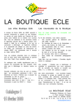
5.2 Valve Connections
Caution! Do NOT use relays or PLC outputs to control solenoid
valves. Use valve outputs directly from the PrecisionAire controller.Valves
operated by 24Vdc solenoids are required for PrecisionAire systems.
Cv is a number expressing the ability of a fluid to flow under
pressure difference or pressure drop. It is also referred to as flow
capacity or flow coefficient. The greater the Cv value, the better the
flow. Cv is analogous to electrical conductance.
The required Cv for valves used in PrecisionAire systems is based
on the motion profile. Cv may affect maximum speed achieved and
response time.
Note: Valve Cv can affect the performance of the PrecisionAire system. Recommended Cv ratings are: PAS10 = Cv 1.2 or
higher; PAS15 = Cv 1.8 or higher. Too much flow is never a
problem with PrecisionAire. Not enough flow can severely
hinder performance.
The following three types of valve configurations (Figures 5.1 to,
5.3) can be used to operate the PrecisionAire system. However, the
solenoid coil response time will affect the in-position settling time of
the system. A solenoid response time of less than 20 ms is required.
The use of two 2-position, 3-way valves directly plumbed to the
PrecisionAire cylinder ports is the preferred method of valving for
optimum performance and required for vertical or long-stroke
5-1
5 : H A R D W A R E
S E T U P
applications. Using a 3-position 4-way valve is an optional
method for short stroke horizontal installations.
When plumbing the air valves to the PrecisionAire actuator,
optimal system performance can be obtained by mounting the
valves in close proximity to the PrecisionAire actuator. By
maintaining short air-line lengths between valve(s) and
PrecisionAire actuator, the response time will be optimized. If valves
cannot be mounted in close proximity to the PrecisionAire actuator,
it is recommended to maintain the same length of air-line for each
valve.
A. Using two 2-position 3-way normally open valves with 24Vdc
solenoids: Connection is shown in Fig. 5.1. When using this
valve configuration Tol-O-Matic recommends "De-Energized"
for the "In Position Valves" selection in the Set-up portion of
the PAS controller software. (see Figure 6.1, pg. 6-4)
Valve A is connected to the actuator non-brake end and valve B
is connected to the brake end.
Black
White 115Vac 60 Hz /
˚230Vac 50 Hz
Green
SEE PAGE 5.6 FOR ENCODER WIRING
—
Encoder
Brake
+
Valve
A
P EA
Air Source
Exhaust
Valve
B
P EB
Air Source
Exhaust
Figure 5.1
3-Way Normally Open Valve Connections
5-2
H A R D W A R E
S E T U P : 5
B. Using two 2-position 3-way normally closed valves with 24Vdc
solenoids: Connection is shown in Fig. 5.2. When using this
valve configuration Tol-O-Matic recommends "Energized" for
the "In Position Valves" selection in the Set-up portion of the
PAS controller software. (see Figure 6.1, pg. 6-4)
Valve A is connected to the actuator non-brake end and valve B is
connected to the brake end.
Black
White
115Vac 60 Hz / 230Vac 50 Hz
Green
SEE PAGE 5.6 FOR ENCODER WIRING
—
Encoder
Brake
+
Valve
A
P EA
Air Source
Exhaust
Valve
B
P EB
Air Source
Exhaust
Figure 5.2
3-Way Normally Closed Valve Connections
5-3
5 : H A R D W A R E
S E T U P
C. Using a 3-position 4-way, spring centered valve with the center
configured with pressure (P) to cylinder ports A and B, with
dual 24Vdc solenoids: Connection is shown in Fig. 5.3. Select
valve "In Position Valve" (default is "De-Energized")(see Figure
6.1, pg. 6-4)
Port A is connected to the actuator non-brake end and port B is
connected to the brake end.
Black
White
115Vac 60 Hz / 230Vac 50 Hz
Green
SEE PAGE 5.6 FOR ENCODER WIRING
➛
+
➛
A
Encoder
Brake
B
A
B
EA
Exhaust
EB
Exhaust
P
Air Source
Fig. 5.3
3 Position 4-Way, Spring Centered Valve Connections
For short stroke, horizontal applications only.
5-4
H A R D W A R E
S E T U P : 5
5.3 Horizontal Applications
For horizontal applications, a two valve (See Figures 5.1and 5.2
system is preferred for optimal performance. However, a single valve
(See figure 5.3) can work for short stroke applications. When
plumbing the PrecisionAire actuator, keep the valve(s) as close to the
actuator as possible. If operating with a single valve or if the valves
cannot be mounted close to the actuator, use air lines of the same
length to optimize the system performance.
5.4 Vertical Applications
For vertical applications, a dual-pressure system (similar to figure
5.1 or 5.2) must be used. Using two separate external pressure
regulators or a valve with a sub-base mounted pressure regulator will
be required to achieve a dual pressure system. Vertical applications
should always be mounted with the brake end at the top. This will
minimize the chance of any belt slack at the brake. Typically the
downward motion will require less then half the pressure of the
upward motion.
Mounting the valve as close as possible to the port of the
PrecisionAire actuator and using equal length air lines will optimize
the PrecisionAire system performance.
5.5 Brake Wiring
Connect the two brake wires to the ‘BRAKE +’ and ‘BRAKE -’
terminals on the controller.
Brake Coil Resistance
PAS10
about 8 Ohms
PAS15
about 4 Ohms
NOTE:
Do NOT connect brake wires across ‘BRAKE +’ and ‘GND’, or ‘BRAKE -’
and ‘GND’ at brake terminal. Do not connect any wires to ‘GND’
Applying AC power to brake terminal will damage controller
permanently. Brake coil may be damaged or shorted when controller is
damaged. None of the brake wire leads are shorted to the brake
housing.
WARNING:
Prior to applying power to controller, test the brake coil resistance. A
shorted brake could permanently damage the controller. Operating at a
brake coil resistance below 7.2 ohms for a PAS10 or 3.6 ohms for a
PAS15 could permanently damage the controller.
5-5
5 : H A R D W A R E
S E T U P
5.6 Encoder Wiring
Encoder pin assignment and color codes are shown in Fig. 5.4.
Tol-O-Matic provides 15 feet of encoder cable.
NOTE:
Do NOT combine encoder wires and brake wires in a single cable. The
encoder may pick up line noise from the brake power signals.
Brake
Shielded
Encoder
RED
WHT
YEL
GRN
BLU
BLK
DRAIN
Figure 5.4 Encoder to PrecisionAire Controller Connections
5.7 115/230 ac Power Wiring
Be sure to set the ac power switch to the correct value (115 or 230
Vac) and connect the line, neutral and ground wires to the terminal
as labeled (Figure 5.5). The factory setting for the controller/drive is
230 Vac.
Do NOT connect ac power to brake terminal.
Figure 5.5 Connect ac power to PrecisionAire controller
5-6
H A R D W A R E
S E T U P : 5
5.8 Input Wiring
The PrecisionAire controller/drive has an ENABLE input that
enables the controller/drive for operation when active.
NOTE 1: If the current is flowing through an input, the logic state of
that input is LOW (i.e., circuit is CLOSED). I/O display on the LCD
should indicate '0' for that input. If no current is flowing the logic
state is HIGH (i.e., circuit is OPEN). I/O display on the LCD will
indicate '1' for the input.
Warning! The ENABLE input should never be used for an
emergency stop or to put the system into a “safe”
condition. Always remove air from the actuator and
power from the controller/drive before servicing
the system.
All the inputs are optically isolated. Each input channel can either
sink or source up to 15 mA. The input channels can be connected
in different ways as illustrated in Fig. 5.6. Tol-O-Matic can supply
both Hall-effect and Reed switches designed to work with
PrecisionAire actuators. Figures 5.7 to 5.9 are sample connection
diagrams for all types of Tol-O-Matic switches.
NOTE 2: In order to accommodate different switch types the INPUT
COM for INPUTS #1, 2, 3 is not internally connected to the INPUT
COM for INPUTS #4, 5, 6, & 7. If using both blocks of inputs, both
INPUT COMs must be hooked up.
NOTE 3: When an input is used for the program pause or feed to
sensor command, the input scanning rate is about 10 ms.
5-7
5 : H A R D W A R E
S E T U P
Figure 5.6 Controller Input Connections
Figure 5.7 Tol-O-Matic Form-A Reed Switch Connections
Figure 5.8 Tol-O-Matic Form-C Reed Switch Connections
5-8
H A R D W A R E
S E T U P : 5
Figure 5.9 Tol-O-Matic Hall-effect Switch Connections
5.9 Output Wiring
The PrecisionAire controller/drive provides two dedicated outputs
to allow the controlling PLC or motion controller to monitor the
controller’s status. They are IN_POSITION and FAULT connections.
All outputs are optically-isolated. Each output channel can either
sink or source up to 20 mA maximum. The output channels can be
connected in different ways as illustrated in Fig. 5.10. There is about
a 100 ms delay while the encoder physically moves into position
before the IN_POS output light turns ON. This delay is necessary to
avoid any false signal when an overshoot occurs.
Figure 5.10 Controller Output Connections
5-9
5 : H A R D W A R E
S E T U P
5.10 Cushions and Shock Absorbers
Unlike the cushions on a regular pneumatic cylinder, the cushions
on a PrecisionAire actuator are only utilized when homing .
Servo positioning within the cushion region is not recommended.
1.0" of stroke on each end should be added to a PAS10 • 1.7" on each
end for a PAS15. Positioning within the cushion region will typically
add more cycle time to a move.
NOTE: Programming speed for a home move is not allowed above 12
in./sec.. However, actual speed will be based upon air pressure,
System Cv, servo parameters, and the load. It is recommended to use
the Data Acquisition to properly set air pressure and servo
parameters prior to homing.
The maximum speed allowed for homing is 12 in/sec (305 mm/sec).
The cushions will handle a load of up to 60 lb (27 kg) for a 1-inch
bore and up to 150 lb (68 kg) for a 1.5-inch bore. If the load exceeds
this limit, a shock will need to be used. When using shock absorbers,
always home towards the shock end. This is especially important
with factory installed shock absorbers as the actuators internal
cushions are removed. Homing away from the shock absorber can
cause damage to the actuator.
5-10
Chapter 6 Software Setup and Programming
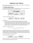
6.1 General Considerations
A. Positional repeatability
REPEATABILITY (inch)
Repeatability
Tolerances
0.03
0.025
0.02
0.015
0.01
0.005
0
0
5
10
15
20
STROKE (feet)
Figure 6.0 Repeatability vs. Stroke
The positional repeatability of the PrecisionAire system can be
programmed to +/- 0.010" (+/- 0.254 mm) with increments of 0.006"
(0.15 mm). Due to belt stretches, piston and bearing frictions,
repeatability at carriage will be greater than +/- 0.010" for stroke
lengths longer than 120 inches. Repeatability at maximum stroke of
18 feet could reach a maximum of +/- 0.025".
Note: Positioning time can be decreased if the In-Position Band is
increased. The lower the In-Position Band is set the greater
likelihood overshoot or servoing into position could occur affecting
the cycle time. It is recommended to operate at the highest InPosition Band possible, this will improve cycle time and reduce
hunting for position.
B. Holding Torque
The in-position holding torque can be set from 0 to 100% of the
maximum brake torque. During dwell time (especially in horizontal
applications), it is often possible to reduce the torque necessary to
hold a load. By reducing the holding torque (as in stepper systems),
the efficiency is improved and the holding device is not required to
dissipate as much heat. This improves the allowable duty cycle. The
factory default holding torque setting is 25%. The maximum holding
torque for a PAS10 is 94 lbs. For a PAS15 251 lbs.
C. Motion profile
Motion profiles are user defined by programming the move distance,
the maximum speed, acceleration time, and deceleration time. How
well the actual motion follows the theoretical profile is based on the
system supply pressure, system Cv, the load, and how well the
system is tuned. During acceleration the brake is released and the
ramp rate is limited by the traditional pneumatic cylinder limitations
mentioned above. During the constant velocity portion of the profile,
encoder information is evaluated to supply a brake current
necessary to maintain the programmed speed. Deceleration is the
most tuning critical portion of the profile. In order to reduce the high
speed thrust requirement of the belt and torque of the brake, both
valves are de-energized to allow air circulation through the valve(s)
during the initial part of the deceleration. The gain settings will
control how linear the deceleration is over the programmed
deceleration time. If the ratio of KT to KI is not appropriately set, a
rapid deceleration will be experienced with a short slow move into
6-1
6 : S O F T W A R E
S E T U P
A N D
P R O G R A M M I N G
final position. Users will experience positioning overshoot on PAS
systems. However, overshoot can be minimized by adjusting servo
settings or deceleration time in the motion profile. Decreasing the
air pressure can also help minimize overshoot as well as increasing
the in-position band. Increasing the in-position band will reduce inposition settling time, if a larger position window is acceptable. Refer
to the Chapter 7 (Tuning) for more detail.
D. Air Cushions
Positioning within the air cushion is not recommended. Doing so
may cause damage to the cylinder. Cushion spears are
approximately 1-inch long for the PAS10 and 1.7 inches for the PAS
15. Ordering an additional 1" of stroke is recommended on each end
of the actuator to avoid positioning within the air cushions.
Positioning within the cushion region will typically add more cycle
time to a move.
6.2 PC Hardware Requirements
•
•
•
An IBM compatible computer running Microsoft Windows® 95,
98, 2000 or NT.
A hard disk with 10 MB of free disk space.
32MB of RAM minimum
6.3 PC Software Installation
•
•
•
•
•
•
6-2
Close all Windows® programs.
Insert the Tol-O-Matic CD and open.
Under ‘Programming Software’ select PrecisionAire software.
Double click to open.
Follow the on-screen instructions that appear.
After installing, run the PrecisionAire software to start motion
control & programming.
S O F T W A R E
S E T U P
A N D
P R O G R A M M I N G : 6
6.4 System Setup
Following are the recommended steps to use once the PrecisionAire
system has been mounted and wired according to the previous
sections.
1. Install software (see 6.3) or if using the integral keypad and LCD,
see Section 6.6.
2. Program the following initial setup parameters (see 6.5 for setup
parameter descriptions)
• Bore size (1 or 1.5 in bore)
• Actuator orientation (horizontal or vertical)
• User unit (inches or mm)
• Stroke length (Specify available stroke length before tuning)
• In-position holding torque (25% as default)
• Select valve "In Position Valve" (default is "De-Energized")
• In-position time out (default to 60 seconds)
• In-position band (default to 0.010" as minimum)
• Software limits (default to OFF)
3. Enable Controller
4. Determine proper air pressure to achieve desired
acceleration/velocity using the Data Acquisitions actual versus
commanded speed. See air system considerations (5.1) for
velocity control. See 7.1 Data Acquisitions for selecting air
pressure example.
5. Determine proper servo gains to achieve desired motion. See
Servo Parameter Gains (6.5) for overshoot/undershoot
considerations. See chapter 7 Tuning for more details.
6. Create and run program (see 6.5)
7. Air pressure, servo gains, deceleration values, and in-position
band may still require adjustment in the setup window or within
the program to optimize performance.
NOTE: If using a replacement controller test the brake coil
resistance prior to applying power to the controller. See 5.5
brake wiring.
6-3
6 : S O F T W A R E
S E T U P
A N D
P R O G R A M M I N G
6.5 Set-up Parameter Definitions
Once the PrecisionAire system has been mounted and wired, setup parameters can be entered by installing the PrecisionAire
software on a PC or by using the Keypad and LCD display. For
procedures on using the keypad and LCD to set up and program,
refer to section 6.7 Setup and Programming from Keypad and LCD.
Figure 6.1 Software Set-up Screen
ACTUATOR PARAMETERS
Actuator stroke, orientation, bore size and valve configuration need
to be assigned before tuning and programming.
To change bore size, select Tools and Advanced Settings.
6-4
S O F T W A R E
S E T U P
A N D
P R O G R A M M I N G : 6
DEFAULT MOTION PARAMETERS
Default motion parameters for maximum speed, accel and decel
times will be used for each new move created in a program.
Parameters can be changed for specific moves in the programming
screen. Performance of the move profile is based on the system
supply of air pressure, valve CV , load and tuning. Data Acquisition
files can help determine achievable acceleration rates and speeds of
your system as well as necessary deceleration rates for desired
performance.
POSITIONING
In-Position Band
The in-position band refers to the repeatability of the system. The
system can be programmed to +/- 0.010" (for strokes of 120" or less)
in 0.006" increments. Repeatability at the carriage will be greater
than +/- 0.010" for strokes longer than 120" due to belt stretches,
piston and bearing frictions. Repeatability for stroke lengths over
120" will automatically be calculated by the controller and displayed
in the appropriate software window.
Note: Positioning time can be decreased if the In-Position Band is
increased. The lower the In-Position Band is set the greater
likelihood overshoot or servoing into position could occur affecting
the cycle time. It is recommended for applications where cycle time
is critical to operate at the highest In-Position Band possible.
In-Position Time Out
In-position time out is the time allocated for the executed move to
reach its desired position before a system error occurs. This is
adjustable from 1 sec to 60 sec.
In-Position Holding Torque
In-position holding torque is the amount of brake pressure applied to
maintain position. Torque can be set from 0 to 100% of maximum
brake torque. During dwell time (especially in horizontal
applications), the amount of brake torque required to hold a load can
often be reduced for improved efficiency. The maximum holding
torque for a PAS10 is 94 lbs. For a PAS15 251 lbs.
6-5
6 : S O F T W A R E
S E T U P
A N D
P R O G R A M M I N G
SERVO PARAMETER GAINS
Servo parameters are used for tuning.
KP Gain
The KP gain determines how sensitive the controller will respond to
a programmed move. Default is set at 40. For most applications, no
adjustment should be necessary.
KI Gain
The KI gain is the controller response to achieving a position.
Default is set at 1. Increase when making small moves of 0.5 inches
or less.
KV Gain
The KV gain is the controller's response to the commanded velocity.
Default is set at 3. Increase when the actual velocity needs to be as
close to the commanded velocity as possible.
Note: See air system considerations 5.1 for velocity control.
KT Gain
The KT gain is the brake response to acceleration. Default is set at
40. Increase if overshooting is present, which will increase the
torque applied to the brake.
Note: Decreasing air pressure, increasing in-position band, or
increasing deceleration time can all reduce overshoot.
ENCODER MONITORING
The encoder monitoring continually checks the encoder for
feedback while a move is taking place. If the programmed time
elapses with no feedback a position fault 03 will occur. Depending
on load, air pressure and tuning the minimum encoder monitoring
time can vary. It is generally recommended to have a time greater
than 300 msec.
6-6
S O F T W A R E
S E T U P
A N D
P R O G R A M M I N G : 6
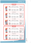
SOFTWARE LIMITS
The position software limits are system "checks".
Forward and Reverse Positions
The forward and reverse position limits of the system are relative to the defined
home position. In (Figure 6.2) the 26" stroke is utilizing 24" of actuator travel
with 1" of extra stroke (as recommended) on each end. The forward position
limit determines how far the carrier will move in a positive direction (toward the
brake) before the system will fault out. If the home position of "0" is determined
4" from the actuator end, the maximum forward position limit for this actuator
would be 21". The Reverse Position limit determines how far the carrier will
move in a negative direction (away from the brake) before a fault occurs. The
maximum negative direction in this case would be –3".
1" RECO
OVERTR MMENDED
AVEL
-3" MAX
26"
24" OF A STROKE
CTUATOR
TRAVEL
IMUM R
EVERSE
HOME
LIMIT
DEFINEPOSITION OF
"
D 4" FR
OM EN 0"
D
21" MA
FORWAXIMUM
RD LIM
IT
1" RECO
OVERTR MMENDED
AVEL
Figure 6.2 Forward and Reverse Position Limits
UNITS
Units can be specified in either a British or Metric unit display.
6-7
6 : S O F T W A R E
S E T U P
A N D
P R O G R A M M I N G
COM PORT
The software accommodates 8 different COM port settings. Clicking
the Auto Find button will automatically find the current COM port
setting.
PASSWORD PROTECTION
For use with the keypad interface, a 4-digit numerical password can
be entered (up to 9999) in order to access program functionality. The
keypad password can be uploaded when uploading the setup
parameters from the controller. A new password will be saved in the
controller EEPROM when setup parameter are downloaded and
saved. Specifying a password of "0" will disable keypad password
protection
6-8
S O F T W A R E
S E T U P
A N D
P R O G R A M M I N G : 6
6.6 Programming from Windows-based PC software
The software contains four main screens: setup, programming,
display & diagnostics and data acquisition.
A. Toolbar Descriptions
a.
b.
c.
d.
e.
f.
g.
h.
i.
j.
k.
l.
m.
n.
o.
p.
q.
New program
Open setup, program or data acquisition file
Save setup, program or data acquisition file
Print
View program source code
Program syntax check
Cut program line(s)
Copy program line(s)
Paste program line(s)
Insert program line
Delete program line(s)
Clear program line(s)
Download setup settings or motion program to controller
Upload controller settings or program to PC
Run program or start display screen update
Stop program or terminate display screen update
Press F1 for the Help menu
6-9
6 : S O F T W A R E
S E T U P
A N D
P R O G R A M M I N G
B. Programming
Click on the ‘PROGRAMMING’ (See Figure 6.3) button to switch
to the programming window. There are 20 commands for
PrecisionAire programming. Users can program or edit multiple
programs at a time. Click on ‘File’ then ‘New’ to start a new program.
Click on a blank program line to display command icons.
.
Figure 6.3 PrecisionAire software – Programming Options
MOVE OPTIONS
1. MOVE — Move the carrier
Users can specify an absolute or incremental move by using the
default move parameters or entering new values (Figure 6.4). Or,
click on the "Teach Position" (See Figure 6.5) button to jog or
manually move the carrier to a desired position for programming.
Enter the desired move distance or position in the distance text box
6-10
S O F T W A R E
S E T U P
A N D
P R O G R A M M I N G : 6
and edit the speed, accel time and decel time text boxes
appropriately for the move.
Note: The absolute direction is always positive toward the brake
end, regardless of which end is used for the home position. If the
brake end is defined as the zero position, negative absolute values
must be used.
Figure 6.9 Move Command
Figure 6.4 Move Command
Figure 6.5 Teach Command
2. MOVE & OUTPUT — Move carrier and set output
This is similar to the move command, but gives the option of setting
an output during or at the end of a move. (See figures 6.6-6.7)
Note: If setting an output at the end of a move profile, the distance
entered in ‘after distance traveled’ must be equal to the move
6-11
6 : S O F T W A R E
S E T U P
A N D
P R O G R A M M I N G
command distance entered. The output will be set when the
actuator servos into position and the in-position light comes on.
This accommodates for any possible overshoot. If the distance
entered in the ‘after distance traveled’ is not equal to the move
command distance the output will be set when the encoder sees
this position reached regardless of possible overshoot. This could
create a condition where the output is set while the actuator
overshoots and servos back to the position.
When programming with the LCD and keypad interface, combine
"AFTER DISTANCE" and "FEED TO POSITION" (or "FEED TO
DISTANCE") commands for Move & Output.
TO DISTANCE") commands for Move & Output.
Figure 6.6 Move and Set Output Command (move)
Figure 6.7 Move and Set Output Command (set output)
6-12
S O F T W A R E
S E T U P
A N D
P R O G R A M M I N G : 6
3. WAIT TIME — Delay for a period of time
Specify the desired delay time in the program. The time unit is
determined from the setup window. (Figure 6.8)
Note: Wait times using a variable are set in msec.
Figure 6.8 Wait Time Command
4. SEEK HOME – homing the carrier
Select the homing direction. (See Figure 6.9) The controller will use
the default speed of a maximum limit of 12 in./sec. Users can select a
lower speed if desired. Homing will move the carrier to the end of the
actuator you specified and then set the position to absolute zero.
Please refer to section 5.9: Cushions and shocks for load weight
requirements when homing.
Warning: Speeds greater than 12 in./sec. could occur on a homing
routine potentially damaging the actuator. Speeds are based upon
air pressure available, Cv of the valve, and servo gains set for the
move. A system must be properly tuned to insure 12 in./sec. speed
is achieved on a homing routine.
Figure 6.9 Seek Home Command
6-13
6 : S O F T W A R E
S E T U P
A N D
P R O G R A M M I N G
I/O OPTIONS
5. FEED TO SENSOR — Moves the carrier until the given
input condition is reached
Allows stopping at any point during a programmed move based on
controller input(s). (Figure 6.10) Single or multiple inputs can be
selected. Feed to Sensor can be positioned two ways, at the point of
deceleration or at the input signal. When positioning at point of
deceleration the controller decelerates to a stop after the input
condition is met and registers in position. When positioning at the
input signal the controller servos to the position where the input
condition was seen and registers in position.
Figure 6.10 Feed to Sensor Command
6. WAIT INPUT – Wait for one or multiple inputs
For a single input, choose the input channel and specify its status
(circuit open or circuit closed) (Figure 6.11). For multiple inputs,
(Figure 6.12) the controller will wait until the exact input status
matches the binary value specified by the user.
NOTE: For Binary value a checked box designates circuit closed.
6-14
S O F T W A R E
S E T U P
A N D
P R O G R A M M I N G : 6
Figure 6.11 Wait for Single Input
Figure 6.12 Wait for Multiple Inputs
7. PAUSE ON INPUT – Pauses a program at any time
The controller will scan the specified inputs and motion will stop,
pausing the motion when input is triggered. Move will resume once
input it cleared. (Figure 6.13) Stop time for pause on input is
proportional to the deceleration time setting in program. This needs
to be set only once at the beginning of the program or where needed.
It will stay in effect until turned off.
6-15
6 : S O F T W A R E
S E T U P
A N D
P R O G R A M M I N G
Figure 6.13 Pause on Input Command
8. SET OUTPUT – Set one or multiple outputs
For setting a single output, as shown in Fig. 6.14, select the desired
output channel and choose its status (high or low) and click ‘OK’ to
continue. For setting multiple outputs, as shown in Fig. 6.15, check
the output channels to set high or uncheck them to set low.
Figure 6.14 Setting a Single Output
6-16
S O F T W A R E
S E T U P
A N D
P R O G R A M M I N G : 6
Figure 6.15 Setting Multiple Outputs
LOOPING OPTIONS
9. REPEAT — Repeats a Loop
Specify the number of loops to repeat. Be sure to end the repeat
section by the end repeat command. (Figure 6.16) The PrecisionAire
controller can allow up to 16 levels deep of nested repeat loop
Figure 6.16 Repeat Loop Command
10. End Repeat – end of repeat loop
Controller will branch to the beginning of the repeat loop until
specified number of loops has been fulfilled.
6-17
6 : S O F T W A R E
S E T U P
A N D
P R O G R A M M I N G
11. Go To – branch program to different location
The line number specifies which line the program should branch. A
"GoTo line 1" would jump back to the beginning of the program. You
can also go to a program number and call a subroutine. When using
a subroutine call, the program it calls must end in an end of
subroutine command. The controller will allow up to 8-levels deep of
nested subroutine calls. For a single input, (Figure 6.17) choose the
input and its status Circuit Open or Circuit Closed. For multiple
inputs, (Figure 6.18) the controller will branch to the specified
location when the exact input status matches the binary value
specified by the user. A conditional jump may also be specified when
branching is dependent on an input or a variable.
It is not recommended that the GoTo command be used within a
repeat or used to jump into a repeat loop unless the user has
considerable programming experience. Doing so can cause
unexpected carrier motion and/or system faults if not programmed
properly.
Figure 6.17 Go To Line Number
Figure 6.18 Go To Program Number
6-18
S O F T W A R E
S E T U P
A N D
P R O G R A M M I N G : 6
12. END SUBROUTINE – Used after a subroutine call to end
the subroutine
SETTING OPTIONS
13. DEFINE POSITION — Define current encoder position
as specified by user.
Figure 6.19 Define encoder position command
14. SET VARIABLE
There are 64 variables available for more complex programming
needs. Numerical values, encoder position, commanded position,
commanded speed, maximum speed and move times can be
specified for any variable. (See Figure 6.20) Clicking on a red "Value"
button in any of the applicable command options will allow a
variable to be set for that function.
An 8 character alpha and/or numeric description can be applied to
any variable. To change the name of a variable, select "Tools" from
the menu and select "View Variable Names".
It is necessary, when selecting, to enter a numerical value to specify
if the value entered is a position or speed. This tells the program to
convert the value to encoder counts.
6-19
6 : S O F T W A R E
S E T U P
A N D
P R O G R A M M I N G
Figure 6.20 Set Variable Command
15. IN-POSITION BAND — Desired positional repeatability
The in-position band can be changed within a program if a different
repeatability is required for a specific move. (Figure 6.21)
Figure 6.21 In-Position Band Command
16. OPERATION MODE — Selection of servo or thrust
mode. In-position holding torque can be changed in thrust
mode.
Servo mode is used for positioning. By switching to thrust mode,
instead of looking for a fixed position, a direction is selected and the
holding torque placed on the brake becomes the amount of thrust
applied to the load. A wait time or wait for input is typically used in
conjunction with thrust mode, then it is switched back into servo
mode in order to complete the next move. (Figure 6.22 and 6.23)
6-20
S O F T W A R E
S E T U P
A N D
P R O G R A M M I N G : 6
Figure 6.22 Operation Mode Command: Servo Mode
Figure 6.23 Operation Mode Command: Thrust Mode
17. SERVO SETTINGS — Changes the default settings
Default settings made in the set up screen can be changed at any
time in the program for individual moves, resulting in optimal
carrier performance to minimize carrier over and undershoot.
(Figure 6.24)
NOTE: This may be necessary if programming moves of different
speeds and/or forces, or if load weight changes.
6-21
6 : S O F T W A R E
S E T U P
A N D
P R O G R A M M I N G
Figure 6.24 Servo Setting Command
18. SOFTWARE LIMITS — Enables or disables previously
set software limits
Figure 6.25 Software Limits Command
COMMENT OPTION
20. COMMENT — Insert text information into a program
Note: Blank comment lines will be stored as a blank line with no data.
Figure 6.27 Comment Command
6-22
S O F T W A R E
C.
S E T U P
A N D
P R O G R A M M I N G : 6
User interface option
The PrecisionAire controller has the option of a keypad and LCD
display panel. (See 6.7 for programming with keypad.) The keypad
and LCD panel can be used as an embedded operator interface by
using the prompt command in the programming options. This
command can be used to prompt a message or variable value at any
point in a program for other users to enter job values or operator
alerts. Move distances, speeds, acceleration and deceleration rates
can be entered or modified. As well as repeat count values, wait
times and operator messages.
PROMPT — Prompt a message or variable
If using a PrecisionAire controller with the LCD panel, this command
may be used to prompt a message or a variable value at any point in
a program for other users to enter job values or operator alert.
(Figure 6.26)
Figure 6.26 Prompt Command
6-23
6 : S O F T W A R E
D.
S E T U P
A N D
P R O G R A M M I N G
View/edit variable
Choose 'tools' from the file menu bar and select 'view variable
names' to open the variable screen as shown in Fig. 6.28. Users can
define variable values or change variable names (up to 8 characters
each) by clicking on the desired cell on the spread sheet. Variable
values are in encoder counts (if position or speed related), or
milliseconds (if time related). If position or speed related enter
distance or speed in inches then use 'Convert to Encoder Counts'
button to determine counts. To find position or speed enter the
counts and use 'Convert to Length' button to display the distance or
speed in inches. Variable names and values will automatically be
saved in EEPROM after clicking on 'done'. 'Reset variables' button
will zero all variable values.
Figure 6.28 Variable Screen
E.
Terminal Screen
Choose 'tools' from the file menu bar and select 'terminal windows'
to open a terminal as shown in Figure 6.29. Two-letter terminal
commands can be entered through the command line, and
corresponding reply will be shown in the response text box. This
screen is helpful for users who are familiar with 2-letter commands to
perform higher level system troubleshooting.
6-24
S O F T W A R E
S E T U P
A N D
P R O G R A M M I N G : 6
Figure 6.29 Terminal Window
6-25
6 : S O F T W A R E
S E T U P
A N D
P R O G R A M M I N G
6.7 Setup and Programming from Keypad & LCD
A 3x3 switch array and a 4x20 character LCD display are used for
system setup and programming. The left/right arrow key is used to
jog the carrier backward/forward, select a motion command, change
a decimal place or select the next data entry. The up/down arrow key
is used to scroll the menu, select the next data entry, or change a
value. Use the ‘ENTER’ key to confirm a selection and ‘ESC’ to go
back to last menu without saving changes. The command map for
the keypad and LCD interface is shown next to the keypad as in Fig.
6.31. Please refer to Chapter 9.2 for more information about the LCD
screens.
A. Screen header:
The LCD screen header includes the screen name and helpful
function key information that is shown at the first line of LCD
display. The screen name is helpful for users when referring to the
command map. Available left/right or up/down arrow keys are
prompted at the beginning and end of the header.
Screen Header ➙
âß PROGRAM #00 àá
000>HOME
001>SET SPEED
002>SET ACCEL. TIME
Screen #1
B. Data entry:
Use the up or down arrow key to change the value of data. Use the
left or right arrow keys to change a decimal place or the increment or
decrement by factors of 10.
For example:
1. To increase data value by 20 at initial increment of 1.
Press the left arrow key once, then the up arrow key twice to
increase the value by 20.
2. To decrease the data value by 0.020 at initial increment of 1.
Press the right arrow key twice (decrement 0.01) then the down
arrow key twice to decrease the value by 0.020.
6-26
S O F T W A R E
S E T U P
A N D
P R O G R A M M I N G : 6
C. Save:
The PrecisionAire controller/drive will NOT save any changes
automatically. After editing, select “SAVE PROGRAM” and “SAVE
SETUP PARA.” to save the motion program and system settings to
the EEPROM.
D. Program Single I/O:
Under the “SET OUTPUT”, “WAIT FOR INPUT”, or “IF INPUT
GOTO” command, select the desired I/O channel (using <, or >) and
use down arrow to select the I/O status (HIGH/LOW) for the
command. In screen #2, the program will wait until input channel
#6 goes low or closed. In screen #3, the program will set output #4
high.
âß PROG# 06 L003 âß
âßPROG# 06 L007âß
WAIT UNTIL INPUT 006
GOES LOW
SET OUTPUT 04
TO HIGH
Screen #2
Screen #3
E. Program Multiple I/O:
When programming multiple I/O for the “SET OUTPUT,” “WAIT
FOR INPUT”, or “IF INPUT GOTO” command, the I/O value is
considered as BINARY and the I/O status options are BYTE, &_HI,
or &_LO. The least-significant-bit (LSB) of the binary code
represents input channel #1 and the most-significant-bit (MSB)
represents input #7. For example, the binary code of value 10 is
0001010 (23+21=8+2=10), as shown in table 6.30. I/O channel 2 and 4
are selected. Please refer to Appendix B for a list of binary code up to
decimal value 127.
Output channel
N/A N/A N/A
4
3
2
1
Input channel
7
6
5
4
3
2
1
Binary bit number
6
5
4
3
2
1
0
Binary code (10)
0
0
0
1
0
1
0
Figure 6.30 Binary code of decimal value10 for multiple I/O programming
• BYTE status: In screen #4, the program will wait until input 2 and
4 are HIGH and the other inputs are LOW. The exact I/O status has
to be matched for each channel.
• &_HI status: In screen #5, the program will set output 2 & 4 HIGH
only. Status of output 1 & 3 is not affected.
• &_LO status: In screen #6, the program will jump to line #123 if
6-27
1 : I N T R O D U C T I O N
input 2 & 4 are LOW. Status of other inputs is NOT considered.
âß PROG# 06 L003 âß âß PROG# 06 L003 âß
âß PROG# 06 L003 âß
WAIT UNTIL INPUT 010
GOES BYTE
SET OUTPUT 10
TO &_HI
IF INPUT 010 &_LO
GO TO LINE 123
Screen #4
Screen #5
Screen #6
F. Select Variable Input:
Variable input is available for ‘feed to length’, ‘feed to position’, ‘wait
time’, ‘repeat’, ‘set speed’, ‘accel time’, and ‘set decel time’
commands. To toggle between numerical and variable data entries,
press the ‘CLEAR’ key to zero integer value and press ‘DOWN’ arrow
key.
G. LCD Message & Comment Command:
LCD message prompt and command text can NOT be edited in the
keypad interface. Please use PC software to edit message text.
Figure 6.31 PrecisionAire Keypad Interface
6-28
I N T R O D U C T I O N : 1
MAIN MENU
RUN
EDIT
PROGRAM
HOME
JOG
SETUP
PROGRAM
DISPLAY
ENCODER
POSITION
POSITION
I/O STATUS
ERROR
SAVE SETUP PARA.
SERVO PARAMETERS
JOG OR HOME SPEED
PROPORTIONAL GAIN
INTEGRAL GAIN
VELOCITY GAIN
DECEL. TORQUE GAIN
PROGRAM #
INSERT
DELETE
SAVE PROGRAM
STROKE
HOLDING TORQUE
USER UNIT
BORE SIZE
ORIENTATION
SOFTWARE LIMITS
IN-POS TIMEOUT
POS COMPENSATION
IN-POS VALVE
ERASE FAULT HISTORY
PASSWORD
AUTO EXECUTE PRG.0
FRWD POSITION LIMIT
BKWD POSITION LIMIT
MAX SPEED LIMIT
SPEED ERROR LIMIT
POSITION ACCURACY
Motion Commands
FEED TO LENGTH
FEED TO POSITION
TEACH
WAIT INPUT
WAIT TIME
GOTO
IF INPUT GOTO
SET OUTPUT
REPEAT
END REPEAT
SET SPEED
SET ACCEL TIME
SET DECEL TIME
SOFTWARE LIMIT
DEFINE POSITION
END
AUTO EXECUTION
HOME
AFTER DISTANCE
IN-POS BAND
SERVO SETTINGS
LCD MESSAGE
FEED TO SENSOR
OPERATION MODE
PROGRAM PAUSE
COMMENT
Figure 6.32 Command map of PrecisionAire LCD/keypad interface
6-29
6 : S O F T W A R E
S E T U P
A N D
P R O G R A M M I N G
6.8 Programming Examples
The following examples are based on an actuator with a stroke length
longer than 75 inches using English units with setup parameters
specified and entered beforehand. The controller will home backward
first and move forward to an absolute position of 70.050-in. Five 10inch incremental moves will then be made in the backward direction.
Set output 4 HIGH for 50 ms then LOW when motion completes.
A. Program an example from keypad
1. Go to ‘EDIT’ then ‘PROGRAM’ menu.
2. Press the right arrow key once to select program #01 and
press the ‘ENTER’ key.
3. Press the left arrow key 9 times to display the ‘HOME’
command at line #000 and press ‘ENTER’
4. The home menu is displayed. Leave the default setting
to home the carrier away from brake and press ‘ENTER’
to continue.
5. Press the down arrow key once to select line #001 and
press the right arrow key 11 times to display ‘SET
SPEED’ command and press the ’ENTER’ key.
6. Use the arrow keys to set the speed at 0071 in/s. Press
the ‘ENTER’ key. Press up arrow key to increase value &
left arrow key to change increment.
7. Press the down arrow key once to select line #002 and
press the right arrow key 12 times to display ‘SET
ACCEL. TIME’ command and press ‘ENTER’ key.
8. Use the arrow keys to set the acceleration time at 0250
ms and press the ’ENTER’ key.
9. Press the down the arrow key once to select line #003
and press the right arrow key 13 times to display the
‘SET DECEL. TIME’ command and press the ’ENTER’
key.
10. Use the arrow keys to set the speed at 0250 ms and press
the ‘ENTER’ key.
11. Press the down arrow key once to select line #004. Press
the right arrow key twice to display ‘FEED TO
POSITION’ command and press the ’ENTER’ key.
12. The feed to position screen is displayed. Use the arrow
keys to set the integer value to +70.
13. Press the right arrow key to switch to the decimal field.
Use the up or down arrow key to set the value to
+0070.050 and press ‘ENTER’ to confirm the setting.
14. Press the down arrow key once to select line #005 and
6-30
S O F T W A R E
S E T U P
15.
16.
17.
18.
19.
20.
21.
22.
23.
24.
25.
26.
27.
A N D
P R O G R A M M I N G : 6
press the right arrow key 9 times to display the ‘REPEAT’
command. Press the ‘ENTER’ key.
The repeat menu is displayed. Press the up key 5 times
to set the value to 00005 and press ‘ENTER’ to confirm
the setting.
Press the down arrow key once to scroll the program
menu down to line #006 and press right arrow key once
to display ‘FEED TO LENGTH’ command’ and press
‘ENTER’ key.
The feed to length screen is displayed and use the up
arrow key to set the integer value to +0010.000 and press
the ‘+/-’ key once to toggle the sign to show – 0010.00
and press ‘ENTER’ key.
Press the down arrow key once to select line #007 and
press the right arrow key 10 times to show ‘REPEAT
END’ command. Press ‘ENTER’.
The end of repeat screen is displayed. Press the ‘ENTER’
key to go back.
Press the down arrow key once to select line #008 and
press the right arrow key 8 times to display ‘SET
OUTPUT’ command. Press ‘ENTER’ command.
The set output screen is shown. Press the up arrow key 3
times to select output 4 HIGH and press ‘ENTER’ to
continue.
Press the down arrow key once to select line #009 and
press the right arrow key 5 times to display ‘WAIT TIME’
command and press the ‘ENTER’ command.
The wait time menu is displayed. Use the arrow keys to
set the time to 0050 ms and press ‘ENTER’.
Press the down arrow key once to select line #010 and
press the right arrow key 8 times to display ‘SET
OUTPUT’ command and press ‘ENTER’ command.
The set output will display last output selected, which is
output 4. Press the right arrow key once to select the
next data field and press the up arrow key once to set
output 4 LOW and ‘ENTER’ to continue.
Press the down arrow key once to select line #011 and
press the left arrow key 10 times to display ‘END’
command and press the ‘ENTER’ command. Press
‘ENTER’ again to confirm the selection.
Program completed. Be sure to save the program to
EEPROM. Press ‘ENTER’ and then down arrow key 3
times to select ‘SAVE’ program. Press ‘ENTER’ to save
6-31
6 : S O F T W A R E
S E T U P
A N D
P R O G R A M M I N G
program to EEPROM. The program is shown as follows.
(Figure 6.33)
|< PROGRAM # 01 >|
000 > HOME
002 SET SPEED
003 SET ACCEL. TIME
004 SET DECEL. TIME
005 REPEAT
006 FEED TO LENGTH
007 REPEAT END
008 SET OUTPUT
009 WAIT TIME
010 SET OUTPUT
011 END
Figure 6.33 Program example using keypad interface
B. Program an example from PC software
1. Click on the programming button to start programming.
2. Click line 1 in the program box to bring up the command
screen, click on the ‘Seek Home’ command icon from the
pop-up screen and choose backward (away from brake) in
the seek home window and click ‘OK’
3. Click line 2 in the program box, click on the ‘Move’ icon and
enter 70" in the distance text box and 70 in/s, 250 ms, 250 ms
in the speed, acceleration & deceleration time text boxes
respectively. Choose absolute move type and click ‘OK’
4. Click line 3 in the program box, click on the ‘Repeat’
command icon and set loop times by value to 5 and click ‘OK’
5. Click line 4 in the program box, click on the ‘Move’ icon and
set incremental backward move distance to 10 and click ‘OK’
6. Click line 5 in the program box, click on the ‘End Repeat’
command icon.
7. Click line 6 in the program box, click on the ‘Set Output’ icon
and select output #4 to HIGH and click ‘OK’
8. Click line 7 in the program box, click on the ‘Wait Time’ icon and
enter 50ms in the wait time by value text box and click ‘OK’
9. Click line 8 in the program box, click on the ‘Set Output’ icon
and select output #4 to LOW and click ‘OK’
10. Save the program and download it to controller, using the
toolbar buttons. The example program is shown as follows.
(Figure 6.34)
6-32
S O F T W A R E
S E T U P
A N D
P R O G R A M M I N G : 6
Figure 6.34 Program example using PC software
To run the program click on the run (execute) button on the toolbar.
6-33
6 : S O F T W A R E
S E T U P
A N D
P R O G R A M M I N G
6.9 Example Applications
APPLICATION 1: PART TRANSFER
Description: A machine builder requires a linear positioning system
to transport parts from one station to another using jog pendant.
•
•
•
•
•
Stroke Length: 10 feet
Guided load about 200 lb.
Desired speed: 5 in/s (LOW) and 20 in/s (HIGH), user selectable via an
input.
Customer would like to use a 3-position push button for jogging forward,
stop, and backward
Position repeatability < 0.1 in
Tol-O-Matic Solution:
• Use a PAS15SK120 unit with keypad option.
• Use input #7 for program pause as emergency stop.
• Use input #6 for HI/LO speed selection
• Use input #4 & #5 for jogging forward & backward
• Key programming commands: Feed to sensor, variable, goto
Figure 6.35 Parts transfer program example
6-34
S O F T W A R E
S E T U P
A N D
P R O G R A M M I N G : 6
APPLICATION 2: CLAMPING
Description: A packaging company requires a pneumatic positioning
vise to approach stacked parts and then provide at least 60 PSI of
thrust on stacked items.
• Number of stacked parts varies. Use a proximity sensor to detect presence
of stacked parts.
• Need an output signal when compressing process completes
• Vise is normally open at a pre-defined park position before parts are
loaded
• Part size ranges from 10-20 in
• Load <= 20 lb
• Position repeatability 0.1 in
Tol-O-Matic Solution:
• Use a PAS10SK24 unit with keypad option.
• Use input #4 to detect stacked parts
• Use thrust mode to contact parts slowly and provide 60 PSI of thrust
• Send output 1 high when done
• Key programming commands: Thrust Mode, feed to sensor, move
Figure 6.36 Clamping program example
6-35
6 : S O F T W A R E
S E T U P
A N D
P R O G R A M M I N G
APPLICATION 3: LUMBER CUTTING
Description: A Lumber manufacturer requires a linear positioning
system to cut lumbers in different sizes & quantities.
• Need to allow operator to specify lumber cut length and desired number
of cuts.
• Need to implement a switch to determine a different cut length or
continue current cut size.
• An emergency stop feature is required.
• Prefer control system to continue unfinished job after E-stop.
• Maximum lumber length: 12 feet
• Position repeatability < 0.1 in
Tol-O-Matic Solution:
• Use a PAS10SK144 unit with keypad option.
• Use input #4 to determine new cut size and different number of cuts
• Use input #5 for emergency stop
• Use LCD prompt for input to get cut size & number of cuts from operator’s
entry
• Key programming commands: LCD prompt for input, program pause,
repeat loop
Figure 6.37 Lumber cutting program example
6-36
Chapter 7 Tuning
7.1 Data Acquisition
PrecisionAire software has a data acquisition to help properly adjust
servo gains, supply air pressure, in-position band, and
deceleration/acceleration times for the applications desired speed or
positioning performance. It maybe necessary to change or adjust
these parameters within a program if loads and speeds change.
Note: Air pressure and load changes can affect tuning parameters.
See supply air pressure considerations 5.1 prior to tuning.
There are 3 data types that can be selected for data collection (Figure
7.1). The default data collection-sampling rate is set at 16 msec. Click
on the "start move & data acquisition" button after specifying
absolute move position and speed to start data collection.
Figure 7.1 Start Move and Data Acquisition
A. Position.
The position data type is used to view over or under shoot of the
system. The main factors that affect the positioning of the
PrecisionAire system are: supply air pressure, in-position band,
deceleration time, and servo gains (Kv and Kt the most critical).
Figure 7.2 Position Data
7-1
7 : T U N I N G
B. Brake Current.
The brake current is used to monitor the performance of the
brake. In high cycle, speed, or load applications were brake
temperature could be a factor, the brake current data can be
viewed to monitor brake usage.
Figure 7.3 Brake Current Data
C. Commanded & Actual Speed.
The command versus actual speed data type is used to monitor
the acceleration, velocity, and deceleration at a given air pressure,
load, commanded speed, and servo settings (Kv and Kt the most
critical). This can be used to determine appropriate supply air
pressure for desired speed, the appropriate servo gains for a
determined air pressure and load, and the cycle time of a move.
It is also helpful in adjustments of the servo settings or
deceleration rate for different loads or speeds within the same
program.
Figure 7.4 Command and Actual Speed Data
7-2
T U N I N G : 7
7.2 Tuning
To achieve the desired motion profile or positioning required for
a move profile, system tuning of the PrecisionAire might be
necessary. System tuning can involve changing the supply air
pressure, the deceleration/acceleration move rates, the in-position
bandwidth, and the servo gains. Tuning within a program could be
required for load or speed changes. Tuning may also be required for
positioning moves at different locations along the actuator based
upon the direction and the proximity of the ends due to the
compression characteristics of air.
To optimize tuning, supply air pressure should be set for the
desired acceleration or speed of the highest speed move within a
program. Typically this air pressure will be no more then 10 PSI
above what is required for the desired acceleration or velocity.
Operating at higher air pressures can increase the likelihood of
overshoot/undershoot or system hesitations. The in-position band
should also be set at the application maximum. The lower the inposition band is set the greater likelihood the system will experience
overshoot or excessive servoing into position. Once the air pressure
and in position band are set, the deceleration rates and servo gains
can be used to adjust the tuning to the desired motion profile or
system positioning.
There are four servo parameters in the PrecisionAire system that
users can manually adjust for better performance. Servo gains can
be adjusted in the Setup Parameters or within the program
Fig 7.5a Parameters
Fig 7.5b Adjustment within program
Servo gains will be used from the Setup Parameter unless
changed within a program prior to the move. It may be necessary to
use the data acquisition to properly adjust these parameters for the
desired system speed or positioning performance. Refer to Chapter
7-3
7 : T U N I N G
9.1 for a control algorithm block diagram.
NOTE: All servo settings are in integer format.
A. Proportional Gain (KP):
The KP gain is the position error gain that will determine how
sensitive the controller will respond to the position error. Only
change when making moves smaller than 0.5 inches. The controller
will respond to position error more effectively when increasing the
KP gain. However, setting the KP gain too high will lead the system
toward positioning instability. The default KP gain is set to 40 at the
factory. For most applications, no adjustment should be necessary.
B. Integral gain (KI):
The KI gain is the position error integral gain. The PrecisionAire
controller will accumulate position error while the carrier is
approaching the target position and multiply the error by the
integral gain. The result is used to determine the required brake
current for positioning. The default KI gain is set to 1 at the factory.
Increase when making small moves of 0.5 inches or less.
C. Speed gain (KV):
The KV gain is the speed error gain. The KV gain is the
controller's response to the commanded velocity. Increase when the
actual velocity needs to be as close to the commanded velocity as
possible. However, jerky motion will occur if setting the KV gain too
high. The default KV gain is set to 3 at the factory.
Note: See air system considerations 5.1 for velocity control.
D. Deceleration current constant (KT):
The KT gain is the brake response to acceleration. The KT gain is
used to set the minimum brake current while decelerating the load.
It is used to adjust position overshoot or undershoot of a system.
The KT gain is used in conjunction with the deceleration rate.
Increasing the KT gain or the deceleration rate will reduce overshoot.
Decreasing the KT gain or the deceleration rate will reduce
undershoot. Some applications will require adjustment in both the
KT gain and deceleration rate for individual move profiles. The
default KT constant is set to 40 at the factory.
Note: Decreasing air pressure, increasing in-position band, or
increasing deceleration time can all reduce overshoot.
7-4
T U N I N G : 7
E. Tuning Tips:
a. Overshoot –Decrease air pressure, increase in-position band,
increase KT, or increase decel time.
b. Undershoot – Decrease air pressure, decrease KT, or decrease
deceleration time.
c. Not reaching desired speed -Decrease KV
d. Moving faster than desired speed – Decrease air pressure or
increase KV
e. Does not move after issue move command – increase KP
f. Jerky motion – Decrease air pressure or decrease KV
g. Not reaching desired cycle time – Increase in-position band.
7.3 Tuning Examples
A. Setting proper air pressure.
This example uses a PAS15 1.5 inch bore unit, 62 inch stroke
actuator, a load weight of 60 lbs., and two 2 position 3 way valves.
The desired move is 40 inches at 20 inches/second with an
acceleration rate of 0.25 seconds.
• In the Setup window, Set the acceleration rate to 0.25 seconds
and the deceleration rate to 0.15 seconds. Also set the Servo
parameters to KP 40, KI 1, KV 1, KT 45. (This example uses a large
load weight of 60 lbs, for lighter loads the deceleration rate and
KT gain can be lowered. The large load weight also affects the
acceleration rate achievable.)
• Set the in-position band to a high value. This example uses 0.5 inches.
• Set the air pressure to a low pressure (15-25 PSI).
• Use the Commanded & Actual Speed in the Data Acquisition to
see the speed achievable with the current air pressure. See Fig
7.6a, this data file is with 15 PSI air pressure. Notice the speed
can be achieved but the acceleration rate is not met.
Figure 7.6a
7-5
7 : T U N I N G
•
Increase the air pressure if need be and take another Data
Acquisition file. See Fig 7.6b, this data file is with 40 PSI air
pressure. Notice the high acceleration rates and speeds, this
pressure is too high to optimize the performance of the system.
Figure 7.6b
•
See figure 7.6c for the proper air pressure (25 PSI) for this
example. Notice the speed is higher then desired, but the
acceleration rate is met.
Figure 7.6c
•
Air pressure alternate method: Remove all power. Manually shift
the valves back and forth, adjusting air pressure until speed or
force desired is reached. Warning: Do not slam carrier into the
ends. Damage to actuator will occur.
B. Velocity control
This example uses a PAS15 1.5 inch bore unit, 62 inch stroke
actuator, a load weight of 60 lbs., and two 2 position 3 way valves.
The desired move is 40 inches at 20 inches/second with an
acceleration rate of 0.25 seconds.
7-6
T U N I N G : 7
•
Once the proper air pressure is selected (See setting proper air
pressure example), increase the Kv gain and use the
Command & Actual Speed in the Data Acquisition to adjust
the velocity control. In this example the settings are the same
as figure 7.6c, 25 PSI, KP40, KI 1, KV 1, KT 45. See figure 7.6d,
KV is adjusted to 4.
Note: PrecisionAire systems are not intended for velocity control.
With proper valving, air pressure and tuning it is possible to
achieve ± 10% velocity control of a commanded speed.
However, due to the characteristics of air, a small change in
air flow or pressure can effect the consistency of velocity
control. If velocity control is needed a servo system should be
used.
Figure 7.6d
C. Positioning control.
This example uses a PAS15 1.5 inch bore unit, 62 inch stroke
actuator, a load weight of 60 lbs., and two 2 position 3 way valves.
The desired move is 40 inches at 40 inches/second with an
acceleration rate of 0.5 seconds. The positional accuracy is 0.01
inches.
•
Once the proper air pressure is selected (See setting proper air
pressure example), adjust the deceleration time, KT and KV gains
and use the Position data type in the Data Acquisition to adjust
the position for over or undershoot.
Note: It may be necessary to adjust these gains once the program is
running. Positioning moves at different locations along the
actuator based upon the direction of motion and the proximity
of the ends can have different servo parameters and deceleration
7-7
7 : T U N I N G
rates due to the compression characteristics of air.
•
In this example the air pressure is set at 35 PSI. See Figure 7.7a,
the servo gains are set at KP 40, KI 1, KV 2, KT 40. The
deceleration rate is set at 0.1 seconds. Notice the actuator
overshot 1.81 inches and came back into position.
Figure 7.7a
•
See figure 7.7b. The servo gains are now adjusted to KP 40, KI 1, KV
3, KT 42. The deceleration rate is also changed to 0.15 seconds.
Notice the actuator undershot and moved slowly into position.
Figure 7.7b
•
7-8
To decrease cycle time see figure 7.7c. The servo gains and
deceleration time are the same as figure 7.7b, however, the inposition band is increased to 0.1 inches.
T U N I N G : 7
C. Cycle time control.
Note: Achieving a high positional accuracy and the fastest cycle
time is the most difficult application to achieve with the
PrecisionAire system. A consistent fast cycle time may not be
possible to achieve without increasing the in-position band.
Achieving a high positional accuracy can require 1-2 added seconds
to servoing into position at the end of a move.
Figure 7.7c
7-9
7 : T U N I N G
7-10
Chapter 8 Troubleshooting
NOTE: A voltmeter is required for system troubleshooting.
8.1 Display & Diagnostics
PrecisionAire software has a display & diagnostics to help with
troubleshooting. It displays the I/O status of the controller and also
tests the valve(s) and brake. When testing the valves and brake, we
recommend users set jog speed slower for safety, and to prevent
damage to the system. Jog speeds use the default setup parameters.
Display & diagnostics also allows the user to view the fault history
and reset the controller.
Figure 8.1 Display & Diagnostics Screen
When a fault or error occurs, shut off the air supply, observe the
system status, and follow the corresponding troubleshooting path.
Do not push or pull on the carrier when the servo loop is activated.
Damage or injury may occur if a user does not follow the trouble
shooting procedure correctly.
8.2 Fault (Fault LED is ON):
When a fault or error occurs, shut off the air supply, observe the
system status, and follow the corresponding troubleshooting path.
Do not push or pull on the carrier when the servo loop is activated.
Damage or injury may occur if a user does not follow the trouble
shooting procedure correctly.
A. Use PC software through RS232:
Go to the ‘display & diagnostics’ window and click on the fault
history button to display the last 16 fault messages. The most
8-1
8 : T R O U B L E S H O O T I N G
recent fault is stack on top of the list and the oldest message is at
the bottom of the list.
B. Use keypad & LCD interface:
Go to ‘ERROR’ menu under ‘DISPLAY’ to display the fault history.
The controller EEPROM will hold up to 15 most recent fault
messages. A tabulated fault message and action are listed below.
Fault codes 01 and 02 are considered as system failures. Power
must be recycled to reset the controller. Fault codes 03 thru 0A
can be reset through the enable input.
Fault message (code)
Description
Action
ADC conversion fault (01)
DSP ADC voltage reference LOW.
Contact Tol-O-Matic
Brake current fault (02)
Exceed brake max current
1. Check brake connection
2. Measure brake resistance
1.0 in brake - 7.2 to 8 ohm
1.5 in brake - 3.6 to 4 ohm
3. A jumper should be installed on
controller board J5 for 1.5 in brake
Position fault (03)
Unable to position
1. Increase encoder monitoring
2. Decrease integral gain Ki
3. Increase brake torque decel gain
4. Increase position window
5. Check brake in-line fuse and coil
resistance
Reverse position limit (04)
Exceed reverse position limit
Modify reverse position limit setting
Forward position limit (05)
Exceed forward position limit
Modify forward position limit setting
Maximum speed fault (06)
Exceed maximum speed setting
1. Check commanded speed
2. Increase max speed setting
Speed following error (07)
Exceed speed following error setting
1. Increase speed gain Kv
2. Increase speed error setting
Enable fault (08)
Controller NOT enabled
1. Check enable input wiring
2. See Chapter 5.7 input wiring
Move profile timeout (09)
(Actual move time - commanded
move time) >= timeout setting
1. Check and adjust tuning para.
KV, KI, or KT
2. Increase profile timeout setting
Current following fault (0A)
Brake current following error
1. Check brake wire connection
2. Check brake coil resistance
Figure 8.2 List of controller fault message, description and action plan
8-2
T R O U B L E S H O O T I N G : 8
8.3 Power LED is OFF after Power ON:
Figure 8.3 Flow chart for trouble shooting with power LED off fault
8-3
8 : T R O U B L E S H O O T I N G
8.4 No Communication with Controller:
A.
B.
C.
D.
Refer to Section 8.1 if LED does not light.
Check RS232 connections.
Check to insure proper COMM port is selected.
Check ONLINE Status.
Is the controller power LED on?
Refer to Section 8.1
No
Yes
Is the RS232 cable connected?
Plug in RS232 cable
No
Yes
Is the proper COMM port selected?
Select COMM port from the
drop down field or Auto Find
No
Yes
Does the ONLINE Status occur?
Reset Controller.
Does the ONLINE status occur?
No
Yes
Proceed
No
Yes
Disconnect power
to Controller
Proceed
Yes
Select proper COMM port
Yes
Power up Controller.
Does ONLINE Status occur?
Yes
Proceed
Figure 8.4 Flow chart for checking Controller communications
8-4
No
Contact
Tol-O-Matic
T R O U B L E S H O O T I N G : 8
8.5 No Motion Occurred:
A.
Check ‘ENABLE’ input.
Controller needs to be enabled to perform any motion. Please
refer to Chapter 5.5, input connection under hardware setup in
this manual for input wiring.
B. Check air pressure and hose connection.
C. Check in-position band setting
D. Check valve solenoid connection.
D.1 Use keypad & LCD interface
Figure 8.5 Flow chart for checking valve connection using keypad interface
8-5
8 : T R O U B L E S H O O T I N G
D.2 Use PC software through RS232
Figure 8.6 Flow chart for checking valve connection using PC software
E. Check belt connection
E.1 Disconnect air to the cylinder
E.2 Disconnect brake
E.3 Manually move the carrier and watch the brake shaft turns. If
the brake shaft does not rotate then the timing belt or the belt
clamp inside the actuator may be broken, or belt may be
excessively loose.
8-6
T R O U B L E S H O O T I N G : 8
F Check encoder reading
F.1 Use keypad & LCD interface
Figure 8.7 Flow chart for checking encoder connection using keypad interface
F.2 Use PC software through RS232
Figure 8.8 Flow chart for checking encoder connection using PC software
8-7
8 : T R O U B L E S H O O T I N G
8.6 No LCD Display:
A. Check power switch — 230 Vac or 115 Vac
B. Turn contrast pot C.W. up to 25 turns
C. Bad LCD module or connection, contact Tol-O-Matic
8.7 Carriage Runaway:
User can jog carrier but it runs away when executing a program or
making a single move. It is very likely that the valve(s) connections
are backward. Swap valve forward and backward wires, or swap the
airline connections at the ends of the cylinder. The brake could be
damaged. Test the brake coil resistance. Resistance should be about
8 ohms for a PAS10 and about 4 ohms for a PAS15. Contact Tol-OMatic if the brake is damaged.
8-8
Chapter 9 Technical Information
9.1 Control-block Diagram
Figure 9.1 Precisionaire control-block diagram
9-1
9 : T E C H N I C A L
I N F O R M A T I O N
9.2 LCD Screens
PrecisionAire
Controller
Version 2.04
Copyright (c) 2002
|
MAIN MENU
>RUN
EDIT
DISPLAY
9-2
|
|
RUN MENU
>PROGRAM
HOME
|
|
RUN MENU
PROGRAM
>HOME
|
|
RUN MENU
PROGRAM
HOME
|
|
RUN MENU
>JOG
|
|
RUN PROG
PROG # 00
|
|< RUN HOME >|
PRESS |,| OR <,> TO
HOME
|< RUN JOG
>|
JOG ENABLED
PRESS <STOP> TO STOP
MOTION
* up to 10 motion programs
can be saved to EEPROM
* PrecisionAire *
PROGRAM RUNNING!!!
USE <STOP> TO STOP
EXECUTION.
T E C H N I C A L
I N F O R M A T I O N : 9
9-3
9 : T E C H N I C A L
9-4
I N F O R M A T I O N
T E C H N I C A L
I N F O R M A T I O N : 9
9-5
9 : T E C H N I C A L
9-6
I N F O R M A T I O N
A: Warranty Information
A: Warranty Information
The following product warranty and return goods information summarizes the product warranty and
return policy of Tol-O-Matic. A copy of the formal Return Goods and Field Service Policy is available upon
request.
Defective Equipment
If the user is unable to correct a problem, and the product is defective, the unit may be returned to
any distributor of Tol-O-Matic products for repair or replacement.
There are no field serviceable parts in the controller/drive. If the controller/drive fails, the unit should
be returned to the factory for repair or replacement. To save unnecessary work repair charges, please
verify that the controller/drive unit is defective before returning it for repair.
PrecisionAire controllers/drives are warranted against defects in material and assembly. Limitations
to warranty coverage are detailed in Return Goods and Field Service Policy. Products that have been
modified by the customer, physically mishandled, or otherwise abused through incorrect wiring,
inappropriate settings, and so on, are exempt from the warranty plan.
Return Procedure
To ensure accurate processing and prompt return of any Tol-O-Matic product, the following
procedure must be followed:
1. Call the nearest distributor of Tol-O-Matic product to obtain a Return Material Authorization
(RMA) number. Do not return the controller/drive or any other equipment without a valid RMA
number. Returns lacking a valid RMA number will not be accepted and will be returned to the
sender.
2. Pack the control/drive in the original shipping carton. Tol-O-Matic is not responsible or liable for
damage resulting from improper packing or shipment. Repaired units are shipped via UPS Ground
delivery. If another method of shipping is desired, please indicated this when requesting the RMA
number and include this information with the return unit.
Product Support
PrecisionAire product support is available over the phone. When you call, you should have the
hardware and software manuals at hand. Be prepared to give the following information.
A. The version number of the hardware and software products.
B. The type of hardware that you are using.
C. The fault message and the exact wording of any message that appears on your screen.
D. How you have tried to solve the problem.
Distributor & Representative Network
Tol-O-Matic has a wide network of distributors that are trained to support our products. If you
encounter problems, call the distributor or representative where you purchased the product before
contacting the factory.
A-1
B: Binary Code
B: Binary Code
B-1
C: Technical Reference – Communication Protocol
I N T R O D U C T I O N
What is a Programming Command?
What is a Terminal Command?
Programming commands are used to write a motion program. It is
different from a terminal command that the user can enter on a
terminal. A program is typically created in a plain text format and saved
in user’s PC. After being created in a text format, a program can then be
downloaded to controller and saved in controller EEPROM. After
downloaded to the RAM of PrecisionAire controller, program
commands can be sequentially executed line by line for an application.
Terminal commands are used to set parameters, request information,
execute or terminate a program. Parameters such as actuator stroke
length, servo settings, bore size, or holding torque can be configured in
terminal mode. Program created in text file can be downloaded and
saved in EEPROM in terminal mode. Please refer to the terminal
commands in this reference section for detail descriptions about all
available commands.
Example using Microsoft® Notepad:
Open the notepad application and create a program in text format by
including programming commands as follows. Please refer to the
programming commands in this reference section for details on all
available commands. A program needs to be loaded to RAM in order for
execution. Execution always starts from first line of program
Example using HyperTerminal in Windows:
Open a hyperterminal application with baud rate 19200, 8 data bits,
none parity, one stop bit and none flow control. Check "Echo typed
characters locally" under ASCII setup and select COM port for serial
connection to PAS controller. Command prompt (>) will respond after
hitting ENTER key when communication is established.
To download a program:
1. Type ‘L’ and hit ‘ENTER’ key to switch to download mode.
2. Click on the "Transfer" from file menu bar and choose "Send Text
File …".
3. Open the program file created in notepad.
4. Use ‘Ctrl+C’ to finish program download.
C-1
C: Communication Protocol:
I N T R O D U C T I O N
Example to make a move in hyperterminal
When controller is powered up initially. Please make sure that the servo
loop is activated by send terminal command ‘s’. Then you can use ‘P’
command to specify absolute position then use ‘g’ command to initiate
a move.
The example above shows to make an absolute move to 2000H encoder
counts at acceleration and deceleration time of 080H (128 ms) and
speed of 7000H counts/sec. When a go command ‘g’ is issued, controller
will move carrier to commanded position.
C-2
Technical Reference: Communication Protocol
P R O G R A M M I N G
AD: After Distance
FL1800
AD8000\1801
Syntax:
AD [Data 1] [\ Data 2]
AD8001\0801
Description:
The after distance command is used to trigger output after a distance
specified in Data 1. The after distance command has to be appended
after feed to position (FP) or feed to length (FL) command.
Arguments:
Data 1: 32-bit distance in encoder counts in hexadecimal format,
Or 16-bit address of a variable
Data 2: Output control, after constant distance
100x: Set single output x HIGH (x=1 to 4)
000x: Set single output x LOW (x=1 to 4)
800x: Set multiple output as BYTE (x=0 to Fh)
A00x: Set multiple output HIGH (x=0 to Fh)
C00x: Set multiple output LOW (x=0 to Fh)
Or,
Output control, after variable distance
180x: Set single output x HIGH (x=1 to 4)
080x: Set single output x LOW (x=1 to 4)
880x: Set multiple output as BYTE (x=0 to Fh)
A80x: Set multiple output HIGH (x=0 to Fh)
C80x: Set multiple output LOW (x=0 to Fh)
Type:
Program command
Related Command:
FP – Feed to Position
FL – Feed to Length
Example:
Instruction
AD1000\1001
AD2000\0002
AD1000\800A
AD1000\A00A
AD1000\C00A
SC0050\8000
SC1000\8001
Interpretation
; Turn output 1 HIGH after 4096
; displacement counts
; Turn output 2 LOW after 8192
; displacement counts
; Set output 2 & 4 HIGH and 1 & 3 LOW
; after 4096 displacement counts
; Set output 2 & 4 LOW with the other
; output remain unchanged after 4096
; displacement counts
; Set output 2 & 4 HIGH with the other
; output remain unchanged after 4096
; displacement counts
; Assign constant 0050h to variable #0
; Assign constant 1000h to variable #1
C O M M A N D S
; Feed forward 1800h(6144) encoder counts
; Turn output 1 HIGH after distance stored
; in variable #0
; Turn output 1 LOW after distance stored in
; variable #1
DP: Define Encoder Position
Syntax:
DP [Data 1]
Description:
The set define position command will redefine the current encoder
position to the value specified in Data1.
Arguments:
Data 1:
32-bit encoder in hexadecimal format.
Type:
Program command
Related Command:
FP – Feed to Position
FL – Feed to Length
HM – Carriage Home
Example:
Instruction
DP1000
DPFFFFF000
Interpretation
; Define current position as 4096 counts
; Define current position as –4096 counts
EN:End of Program
Syntax:
EN
Description:
The program end command specify the end of program.
Arguments:
None
Type:
Program command
Related Command:
AU – Auto Execution
Example:
Instruction
EN
Interpretation
; End of program
C-3
C: Communication Protocol:
P R O G R A M M I N G
FI: If Input Goto
Syntax:
FI [Data 1] [Data 2] [\Data3]
Description:
The if input goto command will jump to a command line or program
specified in Data3 if the input condition is TRUE.
Arguments:
Data 1:
Data 2:
Data 3:
16-bit control data to select one of the
following input or jump types.
Goto a line:
0 – Goto line when single input LOW
1 – Goto line when single input HIGH
8 – Goto line when all 7 inputs match status
specified in Data 2
A – Goto line when multiple inputs all LOW
C – Goto line when multiple inputs all HIGH
Goto a program:
1000 – Goto program when single input LOW
1001 – Goto program when single input HIGH
1008 – Goto program when all 7 inputs match status
specified in Data 2
100A – Goto program when multiple inputs all LOW
100C – Goto program when multiple inputs all HIGH
Call a program:
3000 – Call program when single input LOW
3001 – Call program when single input HIGH
3008 – Call program when all 7 inputs match status
specified in Data 2
300A – Call program when multiple inputs all LOW
300C – Call program when multiple inputs all HIGH
Specify one of 7 inputs or input binary
combination in hexadecimal format
Single input - Data 2 = 1 to 7
Multiple inputs – Data 2 = 00h to 7Fh
Specify line number or program number in
hexadecimal format
Line - Data 3 = 00h to FFh
Program – Data 3 = 0 to 9
Type:
Program command
Related Command:
WT – Wait Time
SO – Set Output
WI – Wait For Input
Example:
C-4
Instruction
FI0007\0032
FI00010007\0032
FI00080037\0032
FI000A0037\0032
FI000C0037\0032
FI10000007\0004
FI10010007\0004
FI10080037\0004
FI100A0037\0004
FI100C0037\0004
FI30000007\0004
FI30010007\0004
FI30080037\0004
FI300A0037\0004
FI300C0037\0004
C O M M A N D S
Interpretation
; If input 7 is LOW, goto LINE #50
; If input 7 goes HIGH, goto LINE #50
; If input 4 & 7 are LOW and input
; 1,2,3,5 & 6 are HIGH, goto LINE #50
; If input 1,2,3,5 & 6 are LOW,
; goto LINE #50
; If input 1,2,3,5 & 6 are HIGH,
; goto LINE #50
; If input 7 is LOW, goto PROG #4
; If input 7 goes HIGH, goto PROG #4
; If input 4 & 7 are LOW and input
; 1,2,3,5 & 6 are HIGH, goto PROG #4
; If input 1,2,3,5 & 6 are LOW,
; goto PROG #4
; If input 1,2,3,5 & 6 are HIGH,
; goto PROG #4
; If input 7 is LOW, call PROG #4
; If input 7 goes HIGH, call PROG #4
; If input 4 & 7 are LOW and input
; 1,2,3,5 & 6 are HIGH, call PROG #4
; If input 1,2,3,5 & 6 are LOW,
; call PROG #4
; If input 1,2,3,5 & 6 are HIGH,
; call PROG #4
FL: Feed to Length / Cut to Length
Syntax:
FL [Data 1] [\ Vari D]
Description:
The feed to length command moves carriage by a relative distance in
encoder quadrature counts. Incremental distance can be actually
specified (Data 1) or referred to a double word variable (Vari D). For
“Feed to Length” move, incremental distance is added to last
commanded position. For “Cut to Length” move, incremental distance is
added to current encoder position.
Arguments:
Data 1:
Vari D:
Note:
Type:
Program command
32-bit encoder increments in hexadecimal format
Double word variable address,
Vari D = 80xx, where xx = 00h to 3Fh
Bit 11 of Vari D is used for cut-to-length control flag
Vari D = 0800 or 88xx for incremental move (cut to
length) based on current encoder position.
P R O G R A M M I N G
C O M M A N D S
FL: Feed to Length / Cut to Length (cont.)
Related Command:
FP – Feed to Position
DP – Define Encoder Position
MG – Display Message on LCD & Read Data
FS – Feed to Sensor
OM – Operation Mode
Example:
Instruction
FL1000
FL02008000
FL\8001
FLFFFFF000
CP = 00004000
AP = 00004002
FL1000\0800
FL\883F
Interpretation
; Feed to length 1000h(4096) encoder counts
; Feed to length 2008000h encoder counts
; Make incremental move based on the value
; stored in double word variable #1
; Feed to length -4096 encoder counts
; Commanded position at 4000h
; Current encoder position at 4002h
; Cut to length 1000h to target pos 5002h
; Cut to length specified in variable #63
Communication Protocol : C
FP02008000
FP\800D
FPFFFFF000
FS: Feed to Sensor
Syntax:
FS [Data 1] [Data 2]
Description:
The feed to sensor command combines jog and wait for inputs
functions to move carrier forward or backward (specified in Data 1) until
a specified input status is reached. When an input is detected, PAS
controller will set brake current to 100%, supply pressurized air on both
sides of the cylinder and then drop brake current down to specified inposition holding torque.
Arguments:
Data 1:
FP: Feed to Position
Syntax:
FP [Data 1] [\ Vari D]
Data 2:
Description:
The feed to position command moves carriage to an absolute position
reference to home (0) position in encoder quadrature counts. Absolute
position can be actually specified (Data 1) or referred to a double word
variable (Vari D).
Arguments:
Data 1:
Vari D:
32-bit encoder position in hexadecimal format
Double word variable address,
Vari D = 80xx, where xx = 00h to 3Fh
Type:
Program command
Related Command:
FL – Feed to Length
DP – Define Encoder Position
MG – Display Message on LCD & Read Data
FS – Feed to Sensor
OM – Set Operation Mode
Interpretation
; Feed to position 1000h encoder counts
16-bit data to select one of the following input type
and move direction.
0000h – Move backward until specified input LOW
0001h – Move backward until specified input HIGH
1000h – Move forward until specified input LOW
1001h – Move forward until specified input HIGH
Specify one of 7 inputs or input binary
combination in hexadecimal format
Single input - Data 2 = 1 to 7
Multiple inputs – Data 2 = 00h to 7Fh
Type:
Program & terminal command
Related Command:
FL – Feed to Length
FP – Feed to Position
OM – Set Operation Mode
Example:
Instruction
FS0001
FS10010007
FS10080037
FS000A0037
Example:
Instruction
FP1000
; Feed to position 2008000h encoder counts
; Move to absolute position stored in double
; word variable #13
; Feed to position -4096 encoder counts
FS100C0037
Interpretation
; Keep moving carriage backward until
; input 1 goes LOW
; Move carriage forward until
; input 7 goes HIGH
; Feed forward until input 4 & 7 LOW
; and input 1,2,3,5 & 6 HIGH
; Feed backward until input 1,2,3,5 & 6
; LOW and ignore the other inputs
; Feed forward until input 1,2,3,5 & 6 HIGH
; and ignore the other inputs
C-5
C: Communication Protocol:
P R O G R A M M I N G
FS: Feed to Sensor (cont.)
Program command
Note:
1. Position repeatability of feed to sensor move is determined on move
speed, load, sensor and valve response time, valve Cv, supplied air
pressure and servo settings.
Related Command:
FI – If Input Go to
2. Maximum move speed is limited to activated input duration that can
be sensed by input. PAS requires a minimum input duration of 10
ms.
3. For higher speed application, higher in-position holding torque will
reduce carrier in-position settling time.
GT: Go To
Syntax:
GT [Data 1]
GT [Vari 1] [Data 2] [\ Vari 2]
C O M M A N D S
Example:
Instruction
Interpretation
GT0064
; Go to program line #100 (64h)
GT8000 0264\8001 ; Go to program line #100 if value stored in
; variable #0 is greater than or equal
; to that in variable #1
GT1005
; Go to program #5
GT8002 1606\8003 ; Go to program #6 if value stored in
; variable #2 is not equal to that in
; variable #3
GT3005
; Call program #5
GT8002 3106\8003 ; Call program #6 if value stored in
; variable #2 is greater than that in
; variable #3
HM: Carriage Home
Description:
The goto command will jump program execution to a different line or
different program specified in Data 1. It can also be used to initiate the
jump based on a logical comparison between Vari 1 & 2.
Arguments:
Data 1:
Data 2:
Vari #:
Type:
C-6
Line or program number to specify jump location
in hexadecimal format.
Line – Data 1 = 0h to 0FFh
Program – Data 1 = 1000h to 1009h
Logic control & line or program number to specify
jump location in hexadecimal format.
BIT # F E D C B A 9 8 7 6 5 4 3 2 1 0
Bit F~E: Reserved
Bit D: Goto (0) or program call (1) control bit
Bit C: Jump to line (0) or program (1) control bit
Bit B: Reserved
Bit A~8: Logic control bits.
000 – no logic expression
001 – greater than (>)
010 – greater than or equal (>=)
011 – equal (=)
100 – Less than (<)
101 – Less than or equal (<=)
110 – Not equal (<>)
Bit 7~0: Line number or program number.
Variable address, Vari # = 80xx, where xx = 00h to 3Fh
Syntax:
HM [Data 1]
Description:
The home command will move carriage toward the end of stroke and
define the position as zero position.
Arguments:
Data 1 = 0, home away from the brake
Data 1 = 1, home toward the brake
Type:
Program command
Related Command:
DP – Define Position
Example:
Instruction
HM0
HM1
Interpretation
; Home carriage away from brake
; Home carriage toward brake
P R O G R A M M I N G
C O M M A N D S
Communication Protocol : C
MG: Display Message on LCD & Read Data
NO: Comment, No Operation
Syntax:
MG [Str] [\ Vari]
Syntax: NO
Description:
The display message command will display text message specified in Str
and store data input from keypad to a variable Vari.
Description:
The comment command allow users to comment each program up to
1024 character.
Arguments:
Str:
Note: Maximum NO and MG string buffer is 1024 characters per
program. NO command shares same text memory with MG command.
Vari:
Text string up to 60 characters per command line.
Backlash ‘\’ is reserved for controller internal use.
Variable address
Vari = 80xx for float format variable with user’s unit
& sign conversion, where xx = 00h to 3Fh
Vari = A0xx for integer format variable without
user’s unit & sign conversion, where xx = 00h to 3Fh
Vari = 0 for no data entry, display string only.
Note: Maximum MG and NO string buffer is 1024 characters per
program. MG command shares same text buffer with NO (no operation,
comment) command.
Type:
Program command
MGPlease Enter Wait Time\A002
MGMachine door is open!\0
MG\0
MGPlease Enter Loops\A003
Type:
Program command
Related Command:
MG – Display Message on LCD & Read Data
Example:
Instruction
Interpretation
NOThis is a comment\0 ; Program comment,
; comment string has to be; ended with “\0”
OM: Set Operation Mode
Related Command:
FL – Feed to Length
FP – Feed to Position
WT – Wait For Time
RP – Repeat Loop
SP – Set Speed
TA – Set Acceleration Time
TD – Set Deceleration Time
NO – Comment, No Operation
Example:
Instruction
MGPlease Enter Speed (in/sec)\8001
Arguments:
None
Syntax:
OM [Data 1] [Data 2] \ [Data 3]
Description:
The set operation mode command allows user to configure PAS
controller in regular servo mode or in thrust mode. Data 1 specifies
servo or thrust mode, Data 2 specifies holding torque on brake, and
Data 3 specifies move direction if in thrust mode.
Interpretation
; Display string in LCD.
; Convert speed data entered
; by user from keypad & store; it
to double word vari. #1
; Display string in LCD and
; store wait time to
; variable #2 (integer format)
; Display string in LCD with
; no variable data entry
; Clear LCD screen
; Display string in LCD and
; store # of loops to
; variable #3
Arguments:
Data 1:
Data 2:
Data 3:
16-bit data to select servo or thrust mode.
0000h – Configure controller in regular servo mode
0001h – Configure controller in thrust mode
16-bit data to specify current applied to brake.
Data 2 = 00h to 06Ch
16-bit data to specify thrust mode move direction.
0 – Move carrier backward, away from brake.
1 – Move carrier forward, toward brake.
Type:
Program command
Related Command:
FL – Feed to Length
C-7
C: Communication Protocol:
P R O G R A M M I N G
OM: Set Operation Mode (cont.)
FP – Feed to Position
FS – Feed to Sensor
PI0
PI0001
PI00010007
PI00080037
PI000A0037
Example:
Instruction
OM00010010\0001
Interpretation
; Thrust mode, Move carrier forward
; with brake holding torque of 010h
; Set controller to servo mode with brake
; holding torque of 01Bh
OM001B
PI000C0037
C O M M A N D S
; Disable pause on inputs
; Pause when input 1 goes LOW
; Pause when input 7 goes HIGH
; Pause when input 4 & 7 are LOW
; and input 1,2,3,5 & 6 are HIGH
; Pause when input 1,2,3,5 & 6 are LOW
; and ignore the other inputs
; Pause when input 1,2,3,5 & 6 are HIGH
; and ignore the other inputs
PR: Set Position Repeatability
Note: Terminal command resume (Z) will not resume motion or
program in thrust mode. Program needs to be re-executed after stop (x)
or pause (z) in thrust mode.
PI: Pause Program on Input
Syntax:
PI [Data 1] [Data 2]
Description:
The pause program on inputs command will pause program execution
and stop motion immediately when single or multiple input status is
reached. Data 2 is selected for up to 7 inputs in binary combination.
Note: Program pause will automatically be disabled when jump to a
different program. Use PI0 to disable pause on inputs.
Arguments:
Data 1:
Data 2:
16-bit data to select one of the following input type.
0 - Pause when single input goes LOW
1 – Pause when single input goes HIGH
8 – Pause when all inputs match status specified in
Data 2
A – Pause when multiple inputs are LOW
C – Pause when multiple inputs are HIGH
Specify one of 7 inputs or input binary
combination in hexadecimal format
Single input - Data 2 = 1 to 7
Multiple inputs – Data 2 = 00h to 7Fh
Related Command:
WI – Wait For Input
C-8
Description:
The set position repeatability command will set the position
repeatability to the value specified in Data 1. Minimum of Data 1 is 5
encoder counts.
Arguments:
Data 1:
16-bit data to specify position repeatability in
encoder counts in hexadecimal format. Data 1 =
05h to FFFFh
Type:
Program command
Related Command:
SS – Set Servo Settings
Example:
Instruction
PR0010
PR0005
Interpretation
; Set position repeatability to 16 counts
; Set position repeatability to 5 counts
RE: Repeat End / Return
Syntax:
RE [Data 1]
Description:
The repeat end command specify the end of a repeat loop and will
branch program execution to the beginning of the loop (RP) if the
remaining loop number greater than zero.
Type:
Program command
Example:
Instruction
Syntax:
PR [Data 1]
Interpretation
Arguments:
Data 1 = 0, end of repeat loop
Data 1 = 0054, return of program call
P R O G R A M M I N G
C O M M A N D S
RE: Repeat End / Return (cont.)
Type:
Program command
Communication Protocol : C
The set constant to variable command will assign a constant value
(Data) to a variable (Vari).
Arguments:
Data:
Related Command:
RP – Repeat
Vari:
Example:
Instruction
RE
RE54
Type:
Program command
Interpretation
; End of repeat loop
; Return of program call
RP: Repeat Loop
Syntax:
RP [Data 1] [\ Vari S]
Description:
The repeat command specify number of repeat loops. Controller will
execute program between repeat (RP) and repeat end (RE) for number
of loops that specified in Data 1 or stored in a variable Vari S.
Arguments:
Data 1:
Vari S:
16-bit data to specify number of repeat loops in
hexadecimal format.
Variable address,
Vari S = 80xx, where xx = 00h to 3Fh
Type:
Program command
Related Command:
RE – Repeat End
MG – Display Message on LCD & Read Data
Example:
Instruction
RP0064
RP\8005
Interpretation
; Repeat 100 times
; Repeat number of loops specified in
; variable #5
SC: Set Constant to Variable
16-bit or 32-bit constant value in hexadecimal
format.
Variable address,
Vari = 80xx for variable, where xx = 00h to 3Fh
Related Command:
GT – Go To
MG – Display Message on LCD & Read Data
SV – Store Internal Value to Variable
Example:
Instruction
Interpretation
SC0100\8001
; Assign 0100h to variable #1
SC00402000\8000 ; Assign 00402000h to variable #0
SL: Configure Software Limits
Syntax:
SL [Flag]
Description:
The configure software limits command is use to enable or disable
position and speed limits in a program.
Arguments:
Flag = 0, Disable software limits check
Flag = 1, Enable software limits check.
Type:
Program command
Related Command:
None
Example:
Instruction
SL1
SL0
Interpretation
; Enable software limits
; Disable software limits
Syntax:
SC [Data] [\ Vari ]
Description:
C-9
C: Communication Protocol:
P R O G R A M M I N G
SP: Set Speed
Bit F~D: Reserved
Bit C: Mask bit for KP, 1-write KP in Data 1 to
controller, 0 – do not write KP to controller
Bit B~9: Reserved
Bit 8: Mask bit for KI, 1-write KI in Data 1 to
controller, 0 – do not write KI to controller
Bit 7~5: Reserved
Bit 4: Mask bit for KV, 1-write KV in Data 1 to
controller, 0 – do not write KV to controller
Bit 3~1: Reserved
Bit 0: Mask bit for KT, 1-write KT in Data 1 to
controller, 0 – do not write KT to controller
Syntax:
SP [Data 1] [\ Vari D]
Description:
The set speed command will set move speed in counts per second in
Data 1. It can also take speed data from a double word variable Vari D.
Arguments:
Data 1:
Vari D:
32-bit data to specify speed in counts/sec in
hexadecimal format.
Double word variable address,
Vari D = 80xx, where xx = 00h to 3Fh
Type:
Program command
Related Command:
TA – Set Acceleration time
TD – Set Deceleration Time
MG – Display Message on LCD & Read Data
Example:
Instruction
SP00004000
SP\8003
Interpretation
; Set speed 16384 counts/sec, or 4 encoder
; revolutions per second.
; Set speed using data stored in double word
; variable #3
C O M M A N D S
Type:
Program command
Related Command:
HT – Set In-Position Holding Torque
PR – Set Position Repeatability
Example:
Instruction
SS18030440\1111
SS18010544\0101
Interpretation
; Set KP=24, KI=3, KV=4, KT=64
; Set KI=1, KT=68, but dot write KP & KV
SV: Store Internal Value to Variable
Syntax:
SV [Data] [\ Vari ]
SS: Set Servo Settings
Syntax:
SS [Data 1] [Data 2] [\ Data 3]
Description:
The set servo settings command will set the four servo parameters (KP,
KI, KV, KT) in the program.
Description:
The store internal value to variable command will save value of a
internal data (e.g. position or speed) to a variable (Vari).
Arguments:
Data:
Vari:
Arguments:
Data 1:
Data 2:
Data 3:
C-10
16-bit servo settings in hexadecimal format
BIT # F E D C B A 9 8 7 6 5 4 3 2 1 0
Bit F~8: Setting for KP (0 to 80h)
Bit 7~0: Setting for KI (0 to 20h).
16-bit servo settings in hexadecimal format
BIT # F E D C B A 9 8 7 6 5 4 3 2 1 0
Bit F~8: Setting for KV (0 to 10h)
Bit 7~0: Setting for KT (0 to 6Ch).
Setting mask control
BIT # F E D C B A 9 8 7 6 5 4 3 2 1 0
16-bit or 32-bit data reference in hexadecimal
format.
Variable address,
Vari = 80xx for double word data,
Vari = 90xx for single word data,
Where xx = 00h to 3Fh
Type:
Program command
Related Command:
GT – Go To
MG – Display Message on LCD & Read Data
SC – Set Constant to Variable
P R O G R A M M I N G
Example:
Instruction
SV0000\8001
SV0006\803F
SV0007\901F
C O M M A N D S
TD: Set Deceleration Time
Interpretation
; Store encoder position, ref. address 00, to
; double word variable #1
; Store max. speed, ref. address 06, to
; double word variable #63
; Store move time, ref. address 080, to
; double word variable #31
Note:
INTERNAL DATA
Encoder Position
Commanded Position
Commanded Speed
Maximum Speed
Move Time
ADDRESS REFERENCE
0000
0002
0004
0006
0080
DATA TYPE
32-bit
32-bit
32-bit
32-bit
16-bit
Syntax:
TA [Data 1] [\ Vari S]
Description:
The set acceleration time command will set time in millisecond for
acceleration. It can also take the time specified in a variable Vari S.
Vari S:
16-bit data to specify acceleration time in
milliseconds in hexadecimal format.
Variable address,
Vari S = 80xx, where xx = 00h to 3Fh
Type:
Program & terminal command
Related Command:
SP – Set Speed
TD – Set Deceleration Time
MG – Display Message on LCD & Read Data
Example:
Instruction
TA0064
TA\800B
Syntax:
TD [Data 1] [\ Vari S]
Description:
The set deceleration time command will set time in millisecond for
acceleration. It can also take the time specified in a variable Vari S.
Arguments:
Data 1:
TA: Set Acceleration Time
Arguments:
Data 1:
Communication Protocol : C
Vari S:
16-bit data to specify acceleration time in
milliseconds in hexadecimal format.
Variable address,
Vari S = 80xx, where xx = 00h to 3Fh
Type:
Program & terminal command
Related Command:
SP – Set Speed
TA – Set Acceleration Time
MG – Display Message on LCD & Read Data
Example:
Instruction
TD0100
TD\800F
Interpretation
; Set decel time 256 ms
; Set decel time specified in
; variable #15
WI: Wait For Input
Syntax:
WI [Data 1] [Data 2]
Description:
The wait for input command will pause program execution until single
or multiple input status is reached. It can wait for up to 7 inputs in
binary combination.
Arguments:
Data 1:
Interpretation
; Set accel time 100 ms
; Set accel time specified in
; variable #11
Data 2:
16-bit data to select one of the following input type.
0 - Wait for single input LOW
1 – Wait for single input HIGH
8 – Wait for all 7 inputs match status specified in
Data 2A – Wait for multiple inputs all LOW
C – Wait for multiple inputs all HIGH
Specify one of 7 inputs or input binary
combination in hexadecimal format
Single input - Data 2 = 1 to 7
Multiple inputs – Data 2 = 00h to 7Fh
C-11
C: Communication Protocol:
P R O G R A M M I N G
WI: Wait For Input (cont.)
Type:
Program command
Related Command:
WT – Wait Time
SO – Set Output
FI – If Input Go to
PI – Program Pause on Input
Example:
Instruction
WI0001
WI00010007
WI00080037
WI000A0037
WI000C0037
Interpretation
; Wait for input 1 goes LOW
; Wait for input 7 goes HIGH
; Wait for input 4 & 7 LOW
; and input 1,2,3,5 & 6 HIGH
; Wait for input 1,2,3,5 & 6 LOW
; and ignore the other inputs
; Wait for input 1,2,3,5 & 6 HIGH
; and ignore the other inputs
WT: Wait Time
Syntax:
WI [Data 1] [\ Vari S]
Description:
The wait time command will halt program execution for a period of time
specified in Data 1. It can also wait for a time specified in variable Vari S.
Arguments:
Data 1:
Vari S:
16-bit data to specify wait time in milliseconds in
hexadecimal format.
Variable address,
Vari S = 80xx, where xx = 00h to 3Fh
Type:
Program command
Related Command:
WI – Wait For Input
FI – If Input Go to
MG – Display Message on LCD & Read Data
Example:
Instruction
WT0064
WI\800A
C-12
Interpretation
; Wait for 100 ms
; Wait for time specified in
; variable #10
C O M M A N D S
Technical Reference: Communication Protocol
T E R M I N A L
a: Set Reverse Position Limit
Syntax:
a [HEX_32]
Example:
Instruction
x
H0010
bV
Arguments:
HEX_32 is a 32-bit signed reverse position limit in hexadecimal format.
Related Command:
dm – Display software limits
A – Set forward position limit
Example:
Instruction
aFFFFF000
Interpretation
; Set reverse position limit to –4096 counts
A: Set Forward Position Limit
Interpretation
; Stop servo loop
; Set brake current to 010h
; Set backward valve ON, carrier moves
; away from brake
B: Configure position compensation & program auto
execution
Syntax:
B [Flag]
Arguments:
Flag = 0, set auto execution OFF, position compensation OFF
Flag = 1, set auto execution OFF, position compensation ON
Flag = 8, set auto execution ON, position compensation OFF
Flag = 9, set auto execution ON, position compensation ON
Related Command:
dB – Display position compensation & auto execution flag
Syntax:
A [HEX_32]
Arguments:
HEX_32 is a 32-bit signed forward position limit in hexadecimal format.
Related Command:
dm – Display software limits
a – Set reverse position limit
Example:
Instruction
A00002000
C O M M A N D S
Interpretation
; Set forward position limit to 8192 counts
Example:
Instruction
B1
B9
Interpretation
; Set pos compensation ON, auto exe. OFF
; Set pos compensation ON, auto exe. ON
c: Display keypad password
Syntax:
c
Arguments:
None
bV: Set backward valve ON
Syntax:
bV
Arguments:
None
Related Command:
CO – Set and overwrite keypad interface password
Example:
Instruction
c
CO=04D2
Interpretation
; Display keypad password in HEX
Controller return:
; Password is 04D2 hex or 1234 decimal
Related Command:
fV – Set forward valve ON
H – Set in-position holding torque
FS – Feed to sensor
C-13
C: Communication Protocol:
T E R M I N A L
CO: Set and Overwrite Keypad Interface Password
Syntax:
CO [HEX_16]
Arguments:
CO command will set and overwrite existing keypad password. HEX_16
is the password code from hexadecimal 0h to 270Fh (i.e. 0 to 9999
decimal) for keypad interface.
Related Command:
None
Example:
Instruction
CO04D2
Interpretation
; Set and overwrite keypad password to
; 1234 decimal
Syntax:
Cc
Arguments:
None
Related Command:
Cl – Load position compensation table to RAM
Cs– Save position compensation table to EEPROM
Interpretation
; Display program number
; Program number 1
; Load program #1 position compensation
; table to RAM
Cs: Save Position Compensation Table to EEPROM
Arguments:
None.
Cs will use current program pointer to save compensation table to
EEPROM.
Related Command:
Cc – Clear position compensation table
Cl – Load position compensation table to RAM
Example:
Instruction
dp
Controller return:
PN=0009
Cs
Interpretation
; Display program number
; Program number 9
; Save position compensation table to
; EEPROM program #9
db: Display actuator bore size
Interpretation
; Clear position compensation table in RAM
Cl: Load Position Compensation Table to RAM
Syntax:
Cl
Arguments:
None.
Cl will use current program pointer to load position compensation table
from EEPROM to RAM.
Related Command:
Cc – Clear position compensation table
Cs– Save position compensation table to EEPROM
C-14
Example:
Instruction
dp
Controller return:
PN=0001
Cl
Syntax:
Cs
Cc: Clear Position Compensation Table
Example:
Instruction
Cc
C O M M A N D S
Syntax:
db
Arguments:
None
Related Command:
o – Set actuator bore size
Example:
Instruction
db
Controller return:
BO=0000
Interpretation
; Display bore size
; Bore size 1-in (0)
T E R M I N A L
C O M M A N D S
dB: Display position compensation & auto
execution flag
Arguments:
None
Arguments:
None
Related Command:
B – Configure internal position compensation
Related Command:
i - Set encoder monitoring
Interpretation
; Display position compensation
Example:
Instruction
dE
Controller return:
; Position compensation flag ON (1)
; Program auto execution flag ON (1)
de: Display position error
dc: Display current command
Interpretation
; Display encoder monitoring
;
Syntax:
de
Arguments:
None
Syntax:
dc
Related Command:
dw – Set position repeatability
Arguments:
None
Related Command:
df – Display current feedback
Example:
Instruction
dc
Controller return:
CI=001B
dE: Display encoder monitoring
Syntax:
dE
Syntax:
dB
Example:
Instruction
dB
Controller return:
CF=000
CF=0008
Communication Protocol : C
Interpretation
; Display current command
Example:
Instruction
de
Controller return:
PE=00000002
Interpretation
; Display position error
; Position error = 2 encoder counts
; Current input (PWM command) = 1Bh
df: Display current feedback
dD: Display in-position valve status
Syntax:
df
Syntax:
dD
Arguments:
None
Arguments:
None
Related Command:
dc – Display current command
Related Command:
D – Set in-position valve output
Example:
Instruction
df
Controller return:
AF=00FC
Example:
Instruction
dD
Controller return:
VS=0000
Interpretation
; Display in-position valve status
Interpretation
; Display current feedback
; Analog feedback = FCh counts
; Valve status = both de-energized
dF: Display fault
C-15
C: Communication Protocol:
C O M M A N D S
OP=0000
DO=00C3
Syntax:
dF
; Output byte = 0h
; Internal dedicated output = C3h
Note:
IP – Input byte:
BIT #
7
6
BIT
EN IN7
Arguments:
None
Related Command:
dQ – Display controller fault history
Example:
Instruction
dF
Controller return:
No flt
T E R M I N A L
Interpretation
; Display fault
; No fault
dh: Display in-position holding torque
Syntax:
dh
Arguments:
None
Related Command:
H – Set in-position holding torque
OP – Output byte:
BIT #
7
6
BIT
—
—
5
IN6
4
IN5
3
IN4
5
4
3
2
FAULT IN_Pos OUT4 OUT3
DO – Internal dedicated output byte:
BIT #
7
6
5
4
3
BIT KEY Y KEY X VAL 2 VAL 1 —
BIT 7:
BIT 6:
BIT 5:
BIT 4:
BIT 3:
BIT 2:
BIT 1:
BIT 0:
Keypad row X enable
Keypad column Y enable
Valve 2 (backward) activated
Valve 1 (forward) activated
Reserved
LCD Enable
LCD Read/write
LCD register select
dI: Display integral gain KI
Example:
Instruction
dh
Controller return:
HT=0019
Interpretation
; Display in-position holding torque
Syntax:
dI
; Holding torque = 19h
Arguments:
None
di: Display input/output status
Syntax:
di
Arguments:
None
Related Command:
n – Set output
Example:
Instruction
di
Controller return:
IP=007F
C-16
Related Command:
I – Set integral gain
Example:
Instruction
dI
Controller return:
KI=0001
Interpretation
; Display I/O status
; Input byte = 7Fh
2
IN3
Interpretation
; Display integral gain
; Integral gain KI = 1
2
E
1
IN2
0
IN1
1
OUT2
0
OUT1
1
R/W
0
RS
T E R M I N A L
C O M M A N D S
dk: Display actuator stroke length
Communication Protocol : C
Controller return:
EL=4002
; Executing program 4, line #2
Syntax:
dk
dm: Display software limits
Arguments:
None
Syntax:
dm
Related Command:
k – Set actuator stroke length
Example:
Instruction
dk
Controller return:
SK=00003069
Interpretation
; Display actuator stroke length
; Stroke = 3096h counts
dl: Display load/weight
Syntax:
dl
Arguments:
None
Related Command:
N – Set load/weight
Example:
Instruction
dl
Controller return:
WT=0007
Interpretation
; Display load/weight
; Load/weight = 7
dL: Display executing program & line number
Syntax:
dL
Related Command:
a – Set reverse position limit
A – Set forward position limit
v – Set maximum speed limit
w – Set speed following error limit
L0 – Disable software limit check
L1 – Enable software limit check
Example:
Instruction
dm
Controller return:
RL=FFFFF000
FL=00004000
SL=00010000
SW=1C00
LE=0000
Interpretation
; Display software limits
; Reverse position limit = -4096 counts
; Forward position limit = 16384 counts
; Maximum speed limit = 65536 counts/sec
; Speed following error = 7168 counts/sec
;Software limits disabled
dM: Display selected variable name & data
Syntax:
dM
Arguments:
None
Related Command:
m – Select variable
M – Set variable name or data
Arguments:
None
Related Command:
dp – Display program number
Example:
Instruction
dL
Arguments:
None.
Interpretation
; Display program line number
Example:
Instruction
dM
Controller return:
V#=003F
Vname64=1234
Interpretation
; Display variable
; Variable #63 (3Fh)
; Variable value is 1234h
C-17
C: Communication Protocol:
T E R M I N A L
C O M M A N D S
do: Display overshoot
dp: Display program running status
Syntax:
do
Syntax:
dp
Arguments:
None
Arguments:
None
Example:
Instruction
do
Controller return:
OS=0001
Interpretation
; Display overshoot
; Overshoot = 1 count
dO: Display actuator orientation
Related Command:
dL – Display executing program & line number
Example:
Instruction
dp
Controller return:
PE=1111
Interpretation
; Display program running flag
; Program running
Or
; Program NOT running
Syntax:
dO
PE=0000
Arguments:
None
dq: Display data collection sampling rate
Related Command:
O – Set actuator orientation
Example:
Instruction
dO
Controller return:
OR=0000
Syntax:
dq
Arguments:
None
Interpretation
; Display actuator orientation
Syntax:
dP
Related Command:
S – Set data collection sampling rate
R – Set data collection type
dr –Display data collection type
Example:
Instruction
Interpretation
dq
; Display sampling rate
Controller return:
DQ=0010
; Data sampling rate = 16 ms
Arguments:
None
dQ: Display controller fault history
Related Command:
K – Set proportional gain KP
Syntax:
dQ
Example
Instruction
dP
Controller return:
KP=0018
Arguments:
None
; Orientation = 0 (Horizontal)
dP: Display proportional gain KP
C-18
Interpretation
; Display KP gain
; KP gain = 018h
Related Command:
dF – Display fault
eQ – Clear fault history
T E R M I N A L
C O M M A N D S
Example:
Instruction
Interpretation
dQ
; Display controller fault history
Controller return:
FH=0023333357322534; Fault history, least significant digit (4) is
; the most recent fault.
PH=FF02302654120001 ; Latest bwd pos fault (4) occurs in prog#1
Fault Message (Code)
ADC conversion fault (01)
Brake current fault (02)
Description
DSP ADC voltage reference LOW.
Exceed brake max current
Position fault (03)
Unable to position
Reverse position limit (04)
Forward position limit (05)
Maximum speed fault (06)
Exceed reverse position limit
Exceed forward position limit
Exceed maximum speed setting
Speed following error (07)
Exceed speed following error setting
Enable fault (08)
Controller NOT enabled
Move profile timeout (09)
(Actual move time - commanded
move time) >= timeout setting
Current following fault (0A)
Brake current following error
Communication Protocol : C
Controller return:
DT=0000
; Data type = 0 (position)
dR: Display program execution trace status
Syntax:
dR
Action
Contact Tol-O-Matic
1. Check brake connection
2. Measure brake resistance
1.0 in brake - 8 ohm
1.5 in brake - 4 ohm
3. A jumper should be installed on
controller board J5 for 1.5 in brake
1. Decrease integral gain Ki
2. Increase brake torque decel gain
3. Increase position window
4. Check brake in-line fuse and coil
resistance
Modify reverse position limit setting
Modify forward position limit setting
1. Check commanded speed
2. Increase max speed setting
1. Increase speed gain Kv
2. Increase speed error setting
1. Check enable input wiring
2. See Chapter 5.7 input wiring
1. Check and adjust tuning para.
KV, KI, or KT
2. Increase profile timeout setting
1. Check brake wire connection
2. Check brake coil resistance
Return Data:
BIT # F-B A
9
8
7
6
5
4
3
2
1
0
Desc Rsvd LCD Fault Trace Feed Home Jog Tune Prog In-Pos Move Servo
Sensor
Run
Bit 0: 1-Servo loop running
Bit 6: 1-Homing
Bit 1: 1-Move flag ON
Bit 7: 1-Feed to sensor/input
Bit 2: 1-Carrier in position
Bit 8: 1-Trace mode ON
Bit 3: 1-Program running
Bit 9: 1- Fault
Bit 4: 1-Tuning
Bit A: 1- LCD prompt message
Bit 5: 1-Jogging
Bit F~B: Reserved
Example:
Instruction
dR
Controller return:
CS=0101
Interpretation
; Display controller status
; Servo loop and program trace are ON
ds: Display commanded speed
Syntax:
ds
dr: Display data collection type
Arguments:
None
Syntax:
dr
Related Command:
V – Set commanded speed
Arguments:
None
Example:
Instruction
ds
Controller return:
CS=00004000
Related Command:
S – Set data collection sampling rate
R – Set data collection type
dq – Display data collection sampling rate
Example:
Instruction
dr
Interpretation
; Display commanded speed
; Commanded speed = 16384 counts/sec
Interpretation
; Display data collection type
C-19
C: Communication Protocol:
T E R M I N A L
dS: Display actual maximum speed
Syntax:
dS
C O M M A N D S
Example:
Instruction
dU
Controller return:
UU=0000
Interpretation
; Display user unit
; User unit = 0 (inch)
Arguments:
None
dv: Display actual speed
Related Command:
V – Set commanded speed
dv – Display actual speed
Example:
Instruction
dS
Controller return:
MS=00004800
Interpretation
; Display maximum carrier speed
; Actual max. speed = 18432 counts/sec
Syntax:
dv
Arguments:
None
Related Command:
V – Set commanded speed
dS – Display actual maximum speed
Syntax:
dt
Example:
Instruction
dv
Controller return:
SP=00004000
Arguments:
None
dV: Display velocity gain KV
Related Command:
G – Set deceleration torque constant KT
Syntax:
dV
Example:
Instruction
dt
Controller return:
BT=0033
Arguments:
None
dt: Display deceleration torque constant KT
Interpretation
; Display KT
; Brake torque = 033h
dU: Display user unit
Syntax:
dU
Arguments:
None
Related Command:
U – Set user unit
C-20
Interpretation
; Display actual speed
; Actual speed = 16384 counts/sec
Related Command:
Y – Set velocity gain KV
Example:
Instruction
dV
Controller return:
KV=0005
Interpretation
; Display velocity gain KV
; KV gain = 5
T E R M I N A L
C O M M A N D S
dw: Display position repeatability
Communication Protocol : C
Bit 31~28:
Syntax:
dw
Arguments:
None
Pause status, 0000b – not paused
0001b – pause by terminal
command, ‘z’ or ‘zx’
0010b – paused by inputs
0011b – paused by inputs &
terminal command
Related Command:
de – Display position error
dz: Display firmware revision information
Example:
Instruction
dw
Controller return:
SE=0006
Interpretation
; Display position repeatability
Syntax:
dz
; Position repeatability = 6 counts
Arguments:
None
dx: Display program pause by inputs status
Syntax:
dx
Related Command:
None
Example:
Instruction
dz
Controller return:
PrecisionAire Ver.1.26
Arguments:
None
Interpretation
; Display firmware revision message
Related Command:
z – Halt program execution
Z – Resume program execution
Example:
Instruction
dx
Controller return:
PI = 10000004
PI = 200A0003
Note:
Bit 6~0:
Bit 15~7:
Bit 19~16:
Bit 27~20:
D: Set in-position valve output
Interpretation
; Display program pause by inputs status
; Program pause by terminal command
; Program will pause when input 4 is LOW
or,
; Program pause by inputs 1 & 2
; Pause when both input 1 & 2 are LOW
Input assignment, 01h~07h for single input,
00h~07Fh for multiple inputs
Reserved
Input type,
0000b – single input LOW
0001b – single input HIGH
1000b – multiple inputs BYTE
1100b – multiple inputs &_HI
1010b – multiple inputs &_LO
Reserved
Syntax:
D [Flag]
Arguments:
Flag = 0, set both valve coils de-energized when in-position
Flag = 1, set both valve coils energized when in-position
Related Command:
dD – Display in-position valve status
Example:
Instruction
D1
Interpretation
; Set both valves energized when in-position
C-21
C: Communication Protocol:
T E R M I N A L
e: Jog carriage
Example:
Instruction
x
E00001000
Syntax:
e [Flag]
Arguments:
Flag = 0, jog backward (away from brake)
Flag = 1, jog forward (toward brake)
fV: Set forward valve ON
Arguments:
None
Interpretation
; Activate servo loop
; Jog carriage forward
; Stop jogging
eQ: Clear fault history
Syntax:
eQ
Related Command:
bV – Set backward valve ON
H – Set in-position holding torque
FS – Feed to sensor
Example:
Instruction
x
H0010
fV
Arguments:
None
Syntax:
FS [Data 1] [Data 2]
Interpretation
; Clear fault history
; Display fault history
; Fault code history
; Program # history
E: Define encoder position
Syntax:
E [HEX_32]
Arguments:
HEX_32 is a 32-bit signed encoder position data in hexadecimal format.
Related Command:
P – Display position information
C-22
Interpretation
; Stop servo loop
; Set brake current to 010h
; Set forward valve ON, carrier moves
; toward brake
FS: Feed to Sensor
Related Command:
dQ – Display fault history
Example:
Instruction
eQ
dQ
Controller return:
FH=0000000000000000
PH=FFFFFFFFFFFFFFFF
Interpretation
; Stop motion
; Define current position as 4096 counts
Syntax:
fV
Related Command:
x – Stop motion
Example:
Instruction
s
e1
x
C O M M A N D S
Description:
The feed to sensor command combines jog and wait for inputs
functions to move carrier forward or backward (specified in Data 1) until
a specified input status is reached. When an input is detected, PAS
controller will set brake current fully, supply pressurized air on both
sides of the cylinder and then drop brake current down to specified inposition holding torque.
Arguments:
Data 1:
16-bit data to select one of the following input
type and move direction.
0000h – Move backward until specified input
LOW
0001h – Move backward until specified input
HIGH
1000h – Move forward until specified input
LOW
1001h – Move forward until specified input
HIGH
T E R M I N A L
Data 2:
C O M M A N D S
Specify one of 7 inputs or input binary
combination in hexadecimal format
Single input - Data 2 = 1 to 7
Multiple inputs – Data 2 = 00h to 7Fh
Communication Protocol : C
G: Set deceleration torque constant KT
Syntax:
G [HEX_16]
Related Command:
fV – Set forward valve ON
bV – Set backward valve ON
Arguments:
HEX_16 is a 16-bit unsigned deceleration torque constant in
hexadecimal format.
Example:
Instruction
FS0001
Related Command:
dt – Display deceleration torque constant KT
FS10010007
FS10080037
FS000A0037
FS100C0037
Interpretation
; Keep moving carriage backward until
; input 1 goes LOW
; Move carriage forward until
; input 7 goes HIGH
; Feed forward until input 4 & 7 LOW
; and input 1,2,3,5 & 6 HIGH
; Feed backward until input 1,2,3,5 & 6
; LOW and ignore the other inputs
; Feed forward until input 1,2,3,5 & 6 HIGH
; and ignore the other inputs
Note:
Position repeatability for feed to sensor move may depend on move
speed, load, sensor and valve response time, supplied air pressure and
servo settings.
Maximum move speed is limited to activated input duration that can be
sensed by input. PAS requires a minimum input duration of 10 ms.
Example:
Instruction
G0040
h: Carriage home
Syntax:
h [Flag]
Arguments:
Flag = 0, home backward (away from brake)
Flag = 1, home forward (toward brake)
Related Command:
x – Stop motion
Example:
Instruction
s
h0
g: Go, begin move
Interpretation
; Set KT gain to 64 = 040h
Interpretation
; Activate servo loop
; Home backward
Syntax:
g
H: Set in-position holding torque
Arguments:
None
Syntax:
H [HEX_16]
Related Command:
x – Stop motion
Example:
Instruction
s
P00001000
g
Interpretation
; Activate servo loop
; Set commanded position 4096 counts
; Move to commanded position
Arguments:
HEX_16 is a 16-bit unsigned in-position holding torque in hexadecimal
format.
Related Command:
dh – Display in-position holding torque
Example:
Instruction
H001B
Interpretation
; Set in-position holding torque to 01Bh
C-23
C: Communication Protocol:
T E R M I N A L
C O M M A N D S
I: Set integral gain KI
Syntax:
I [HEX_16]
Example:
Instruction
J4
Arguments:
HEX_16 is a 16-bit unsigned integral gain in hexadecimal format.
k: Set actuator stroke length
Related Command:
dI – Display integral gain KI
Example:
Instruction
I0001
Syntax:
k [HEX_31]
Interpretation
; Set integral gain KI to 01h
Syntax:
i
Example:
Instruction
k00008000
Arguments:
None
Syntax:
K [HEX_16]
Interpretation
;
Arguments:
HEX_16 is a 16-bit unsigned proportional gain in hexadecimal format.
j: Load program from EEPROM to RAM
Syntax:
j [NUM]
Arguments:
NUM is a 4-bit unsigned program number in hexadecimal format. NUM
= 0 to 9.
Related Command:
J – Save program to EEPROM
l – List program
Interpretation
; Load program #4 to RAM
; List program
J:Save program to EEPROM
Syntax:
J [NUM]
Arguments:
NUM is a 4-bit unsigned program number in hexadecimal format. NUM
= 0 to 9.
Related Command:
j – Load program from EEPROM to RAM
C-24
Interpretation
; Set stroke length to 08000h
K: Set proportional gain KP
Related Command:
dE - Display encoder monitoring
Example:
Instruction
j4
l
Arguments:
HEX_31 is a 31-bit unsigned stroke data in encoder counts in
hexadecimal format.
Related Command:
dk – Display actuator stroke length
i: Set encoder monitoring
Example:
Instruction
Interpretation
; Save program to EEPROM program #4
Related Command:
dP – Display proportional gain KP
Example:
Instruction
K0018
Interpretation
; Set KP=018h
l: List program
Syntax:
l
Arguments:
None
Related Command:
j – load program from EEPROM to RAM
Example:
Instruction
l
Controller return:
HM0
FP2000
EN
Interpretation
; List program
; Home backward
; Feed to position 02000h
; End of program
T E R M I N A L
C O M M A N D S
Communication Protocol : C
L: Download program / Configure software limit
M: Set variable name or data
Syntax:
L [Flag]
Syntax:
M [HEX], M*, Mx [TEXT]
Arguments:
None – Download program to RAM
Flag = 0, disable software limits
Flag = 1, enable software limits
Arguments:
HEX is a 16 or 32-bit unsigned data in hexadecimal format.
TEXT is a maximum 8-character string for variable name.
Related Command:
Control+C (^C) – End program download
dm – Display software limits
Example:
Instruction
L
HM0
FP2000
EN
^C
L1
dm
Controller return:
RL=FFFFF000
FL=00004000
SL=00010000
SW=1C00
LE=0001
Interpretation
; Begin load program to RAM
; Home backward
; Feed to position 02000h
; End of program
; End program download
; Enable software limits
; Display software limits
; Reverse position limit = -4096 counts
; Forward position limit = 16384 counts
; Maximum speed limit = 65536 counts/sec
; Speed following error = 7168 counts/sec
; Software limits enabled
Related Command:
dM – Display selected variable name & data
m – Select variable
yV – Save variables to EEPROM
Example:
Instruction
m803F
M1000 1234
MxPOS64
M*
Interpretation
; Select variable #63
; Set 10001234h to selected variable
; Name double variable #63 as “POS64”
; Clear all variables to 0
n: Set output
Syntax:
n [HEX_16]
Arguments:
HEX_16 is the binary combination of 4 output channels as illustrated
below. HEX_16 = 00h to 0Fh
Related Command:
di – Display input/output status
m: Select variable
Example:
Instruction
n000A
Syntax:
m [HEX_16]
Interpretation
; Set output 1 & 3 LOW and 2 & 4 HIGH
; 0Ah = 01010b
N: Set load/weight
Arguments:
HEX_16 is a 16-bit unsigned variable number in hexadecimal format.
Use 8000-803F for variable #0 to #63.
Related Command:
dM – Display selected variable data
M – Set variable name or data
Example:
Instruction
m8000
Syntax:
N [HEX_16]
Arguments:
HEX_16 is a 16-bit unsigned load/weight in hexadecimal format.
Related Command:
dl – Display load/weight
Interpretation
; Select variable #0
Example:
Instruction
N7
Interpretation
; Set load/weight to 7
C-25
C: Communication Protocol:
T E R M I N A L
C O M M A N D S
o: Set actuator bore size
P: Set commanded position
Syntax:
o [Flag]
Syntax:
P [HEX_32]
Arguments:
Flag = 0, 1-in bore
Flag = 1, 1.5-in bore
Arguments:
HEX_32 is a 32-bit signed position data in encoder counts in
hexadecimal format.
Related Command:
db – Display actuator bore size
Related Command:
p – Display position information
Example:
Instruction
o0
Example:
Instruction
P00001000
Interpretation
; Set actuator bore 1-in
Interpretation
; Set commanded position 01000h
q: Quit motion program
O: Set actuator orientation
Syntax:
q
Syntax:
O [Flag]
Arguments:
None
Arguments:
Flag = 0, horizontal
Flag = 1, vertical
Related Command:
dO – Display actuator orientation
Example:
Instruction
O1
Interpretation
; Actuator mounted vertically
Related Command:
r – Run motion program
x – Stop motion
Example:
Instruction
q
Interpretation
; Quit motion program
Q: Controller soft reset
p: Display position information
Syntax:
Q
Syntax:
p
Arguments:
None
Arguments:
None
Related Command:
P – Set commanded position
Example:
Instruction
p
Controller return:
CP=00001000
AP=00001001
C-26
Interpretation
; Display position information
; Commanded position = 4096 counts
; Actual position = 4097 count
Related Command:
None
Example:
Instruction
Interpretation
Q
; Controller reset
Note: Please allow two seconds for internal controller reset. Sending
serial command during controller reset may cause serial port over-run
error. If serial communication is not established, please recycle power or
press reset button to reset controller.
T E R M I N A L
r: Run motion program
Syntax:
r
C O M M A N D S
Communication Protocol : C
Example:
Instruction
s
P1000
g
Interpretation
; Activate servo loop
; Set commanded position 01000h
; Move to commanded position
Arguments:
None
Related Command:
q – Quit motion program
x – Stop motion
Example:
Instruction
j1
s
r
S: Set data collection sampling rate
Syntax:
S [Rate_flag]
Interpretation
; Load program #1 to RAM
; Activate servo loop
; Run program #1
R: Set data collection type
Arguments:
Rate_flag = 3 to 9.
Sampling rate = 2^Rate - flag (ms)
Related Command:
dq – Display data collection sampling rate
Syntax:
R [Flag]
Example:
Instruction
R5
Arguments:
Flag = 0, no data collection
Flag = 1, position data
Flag = 2, actual speed data
Flag = 3, commanded speed
Flag = 4, current feedback data
Flag = F, command & actual speed data
t: Display motion profile time
Related Command:
dr – Display data collection type
Arguments:
None
Example:
Instruction
R1
Related Command:
TA – Set acceleration time
TD – Set deceleration time
TO – Set profile timeout
Interpretation
; Collect position information
s: Activate servo loop
Syntax:
s
Arguments:
None
Interpretation
; Set sampling rate 2^5=32 ms
Syntax:
t
Example:
Instruction
t
Controller return:
TA=0080
TC=0100
TD=0064
TO=0400
Interpretation
; Display motion profile time
; Acceleration time = 128 ms
; Constant speed time = 256 ms
; Deceleration time = 100 ms
; Profile time out = 1024 ms
Related Command:
X – Stop servo loop
C-27
C: Communication Protocol:
T E R M I N A L
C O M M A N D S
TA: Set acceleration time
TR: Set program execution trace mode
Syntax:
TA [HEX_16]
Syntax:
TR [Flag]
Arguments:
HEX_16 is a 16-bit unsigned acceleration time in millisecond in
hexadecimal format.
Arguments:
Flag = 0, program execution trace OFF
Flag = 1, program execution trace ON
Related Command:
dR – Display program execution trace status
Related Command:
t – Display motion profile time
Example:
Instruction
TA0080
Interpretation
; Set acceleration time 080h = 128 ms
Example:
Instruction
TR1
Interpretation
; Set trace mode ON
u: Upload collected data
TD: Set deceleration time
Syntax:
u [Flag]
Syntax:
TD [HEX_16]
Arguments:
HEX_16 is a 16-bit unsigned deceleration in millisecond in hexadecimal
format.
Related Command:
t – Display motion profile time
Example:
Instruction
TD0064
Interpretation
; Set acceleration time 064h = 100ms
Arguments:
Flag = 0, 32-bit data (position, speed, commanded speed)
Flag = 1, 16-bit data (current feedback)
Related Command:
R – Set data collection type
S – Set data collection sampling rate
UT – Upload tuning speed data
Example:
Instruction
u1
Interpretation
; upload 16-bit data
TO: Set profile timeout
uT: Upload tuning speed data
Syntax:
TO [HEX_16]
Syntax:
uT
Arguments:
HEX_16 is a 16-bit unsigned profile timeout in millisecond in
hexadecimal format.
Arguments:
None
Related Command:
t – Display motion profile time
Related Command:
u – Upload collected data
Example:
Instruction
TO0400
Example:
Instruction
uT
C-28
Interpretation
; Set profile timeout 400h = 1024 ms
Interpretation
; upload 32-bit tuning speed data
T E R M I N A L
C O M M A N D S
Communication Protocol : C
U: Set user unit
w: Set speed following error limit
Syntax:
U [Flag]
Syntax:
w [HEX_16]
Arguments:
Flag = 0, inch
Flag = 1, mm
Arguments:
HEX_16 is the speed following error in counts per second in
hexadecimal format.
Related Command:
du – Display user unit
Related Command:
dm – Display software limits
Example:
Instruction
U1
Interpretation
; Set user unit to mm
Example:
Instruction
w1c00
Interpretation
; Set speed following error limit to 1c00h
; counts/sec
v: Set maximum speed limit
W: Set position repeatability
Syntax:
v [HEX_32]
Syntax:
W [HEX_16]
Arguments:
HEX_32 is the maximum speed in counts per second in hexadecimal
format.
Arguments:
HEX_16 is the position repeatability in counts in hexadecimal format.
Related Command:
dm – Display software limits
Related Command:
dw – Display position repeatability
Example:
Instruction
v00010000
Example:
Instruction
W0005
Interpretation
; Set max. speed limit to 10000h counts/sec
V: Set commanded speed
x: Stop motion
Syntax:
V [HEX_32]
Syntax:
x
Arguments:
HEX_32 is the commanded speed in counts per second in hexadecimal
format.
Arguments:
None
Related Command:
e – Jog carriage
g – Go, begin move
h – Carriage home
r – Run motion program
Related Command:
ds – Display actual speed
Example:
Instruction
V00008000
Interpretation
; set position repeatability to +/- 5 counts
Interpretation
; Set commanded speed to 8000h counts/sec
C-29
C: Communication Protocol:
Example:
Instruction
x
Interpretation
; Stop motion
T E R M I N A L
Example:
Instruction
yV
C O M M A N D S
Interpretation
; Save variable data and names to EEPROM
X: Stop servo loop
Y: Set velocity gain KV
Syntax:
X
Syntax:
Y [HEX_16]
Arguments:
None
Arguments:
HEX_16 is the velocity gain in hexadecimal format.
Related Command:
s – Activate servo loop
Related Command:
dV – Display velocity gain KV
Example:
Instruction
X
Interpretation
; Stop servo loop
y: Save controller settings
Syntax:
y
z: Halt program execution after finishing current
command
Arguments:
None.
Related Command:
None.
Related Command:
Z – Resume program execution
Interpretation
; Save controller settings to EEPROM
yV: Save variables to EEPROM
Syntax:
yV
Arguments:
None.
Related Command:
dM – Display selected variable data
m – Select variable
M – Set variable name or data
C-30
Interpretation
; Set velocity gain KV to 5
Syntax:
z
Arguments:
None.
Example:
Instruction
y
Example:
Instruction
Y0005
Example:
Instruction
z
Interpretation
; Halt program execution after finishing
current command
T E R M I N A L
C O M M A N D S
zx: Halt program execution and stop motion
immediately
Arguments:
None.
Arguments:
None.
Related Command:
Z – Resume program execution
Z
^C: End Program Download
Syntax:
Control + C
Syntax:
zx
Example:
Instruction
zx
Communication Protocol : C
Interpretation
; Halt program execution and stop move
; right away
; Resume program and continue unfinished
; move
Related Command:
L– Download program to RAM
Example:
Instruction
L
^C
Interpretation
; Download program begins
; Send text motion program here
; End program downloadzzz
Z: Resume program execution
Syntax:
Z
Arguments:
None.
Related Command:
z – Halt program execution
Example:
Instruction
Z
Interpretation
; Resume program execution
C-31
TOL-O-MATIC, INC.
3800 County Road 116
Hamel, MN 55340
763.478.8000 Telephone
800.328.2174 Toll Free
763.478.8707 Fax
http://www.tolomatic.com