1
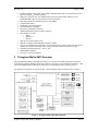
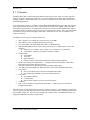
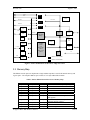
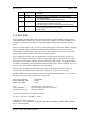
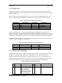
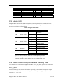
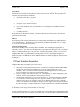
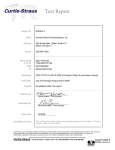
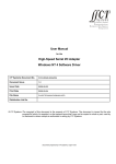
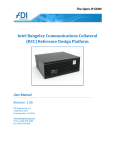
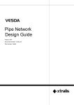
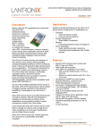
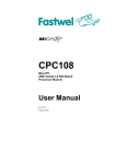
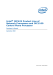
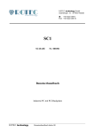
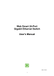
Pronghorn Metro SBC Hardware Manual Quad Radio Wireless Router Board ADI Engineering, Inc. 1769A Worth Park Charlottesville, VA 22911 http://www.adiengineering.com Phone: (434) 978-2888 Fax: (434) 978-1803 1 of 22 COPYRIGHT & TRADEMARKS Specifications are subject to change without notice. Copyright © 2006 ADI Engineering, All Rights Reserved. All other trademarks and brand names are the property of their respective proprietors. LIMITED WARRANTY ADI Engineering guarantees that every Pronghorn Metro unit will be free from physical defects in material and workmanship for one year from the date of purchase, when used within the limits set forth in the Specifications section of this User Guide. If the product proves defective during this warranty period, call ADI Engineering Technical Support in order to obtain a Return Authorization number. When returning a product, mark the Return Authorization number clearly on the outside of the package and include a copy of your original proof of purchase. All customers shall be held responsible for return shipping and handling charges. IN NO EVENT SHALL ADI ENGINEERING’S LIABILITY EXCEED THE PRICE PAID FOR THE PRODUCT FROM DIRECT, INDIRECT, SPECIAL, INCIDENTAL, OR CONSEQUENTIAL DAMAGES RESULTING FROM THE USE OF THE PRODUCT, ITS ACCOMPANYING SOFTWARE, OR ITS DOCUMENTATION. ADI ENGINEERING OFFERS NO REFUNDS FOR ITS PRODUCTS. ADI Engineering makes no warranty or representation, expressed, implied, or statutory, with respect to its products or the contents or use of this documentation and all accompanying software, and specifically disclaims its quality, performance, merchantability, or fitness for any particular purpose. ADI Engineering reserves the right to revise or update its products, software, or documentation without obligation to notify any individual or entity. Please direct all inquiries to: ADI Engineering, 1769A Worth Park, Charlottesville, VA 22911. SAFETY AND REGULATORY NOTICES FCC STATEMENT The Pronghorn Metro SBC Wireless Router Board has been tested and found to comply with the specifications for a Class B digital device, pursuant to Part 15 of the FCC Rules. Operation is subject to the following two conditions: (1) This device may not cause harmful interference, and (2) This device must accept any interference received, including interference that may cause undesired operation. These limits are designed to provide reasonable protection against harmful interference in a residential installation. This equipment generates, uses, and can radiate radio frequency energy and, if not installed and used according to the instructions, may cause harmful interference to radio communications. However, there is no guarantee that interference will not occur in a particular installation. If this equipment does cause harmful interference to radio or television reception, which is found by turning the equipment off and on, the user is encouraged to try to correct the interference by one or more of the following measures: • Reorient or relocate the receiving antenna • Increase the separation between the equipment or devices • Connect the equipment to an outlet other than the receiver's • Consult a dealer or an experienced radio/TV technician for assistance FCC Caution: Any change or modification to the product not expressly approved by ADI Engineering could void the user's authority to operate the device. 2 of 22 Revision 1.20 August 3, 2007 Revisions Date Revision Page-paragraph 1 Apr 06 12 May 06 19 Jun 06 0.01 1.0 1.1 All 3.16 All 31 Jul 07 1.2 All Pronghorn Metro SBC Hardware Manual Remarks New Document Changed text to match hardware watchdog operation Changed to reflect final production hardware, updated Linux and Redboot sections Changed to reflect Version 3.0 of the board 3 of 22 Revision 1.20 August 3, 2007 Table of Contents 1 INTRODUCTION ................................................................................................................................ 7 2 KEY FEATURES OF PRONGHORN METRO SBC....................................................................... 7 3 PRONGHORN METRO SBC OVERVIEW ..................................................................................... 8 3.1 3.2 3.3 3.4 3.5 3.6 3.7 3.8 3.9 3.10 3.11 3.12 3.13 3.14 3.15 3.16 3.17 3.18 PROCESSOR ................................................................................................................................... 10 MEMORY MAP............................................................................................................................... 11 SDRAM MEMORY ........................................................................................................................ 12 EXPANSION BUS ............................................................................................................................ 13 COMPACT FLASH ........................................................................................................................... 13 VOLTAGE AND TEMPERATURE MONITORING ................................................................................ 13 COVER OPEN DETECT ................................................................................................................... 13 DEVICES ON THE EXPANSION BUS ................................................................................................. 14 CONFIGURATION STRAPS .............................................................................................................. 14 BOOT ROM................................................................................................................................... 15 MINI PCI ....................................................................................................................................... 16 ETHERNET INTERFACES ................................................................................................................. 17 SERIAL PORTS ............................................................................................................................... 18 IXP425 JTAG INTERFACE............................................................................................................. 18 INDICATOR LED’S......................................................................................................................... 19 PLATFORM RESET CIRCUITRY AND HARDWARE WATCHDOG TIMER ............................................ 19 POWER SUPPLIES, REGULATORS.................................................................................................... 20 MECHANICAL ................................................................................................................................ 22 Pronghorn Metro SBC Hardware Manual 4 of 22 Revision 1.20 August 3, 2007 Table of Figures FIGURE 1. PRONGHORN METRO SBC BLOCK DIAGRAM ................................................................................. 8 FIGURE 2. INTEL ® IXP425 NETWORK PROCESSOR: HIGH-LEVEL VIEW ..................................................... 11 FIGURE 3. IMPLEMENTATION OF ETHERNET PORTS ...................................................................................... 17 Pronghorn Metro SBC Hardware Manual 5 of 22 Revision 1.20 August 3, 2007 Table of Tables TABLE 1. PRONGHORN METRO SBC SPECIFICATIONS ..................................................................................... 9 TABLE 2. INTEL ® IXP425 NETWORK PROCESSOR: MEMORY MAP .............................................................. 11 TABLE 3. CHIP SELECTS FOR DEVICES CONNECTED TO EXPANSION BUS ...................................................... 14 TABLE 4. PRONGHORN METRO CONFIGURATION STRAPPINGS ...................................................................... 14 TABLE 5. USER SERIAL PORT (UART1), 9-PIN CONNECTOR......................................................................... 18 TABLE 6. DEVELOPMENT SERIAL PORT (UART0), 6-PIN HEADER ................................................................ 18 TABLE 7. IXP425 JTAG CONNECTOR PINOUT .............................................................................................. 18 TABLE 8. PRONGHORN METRO LED’S .......................................................................................................... 19 TABLE 9. J10, J11 POWER INPUT PINOUTS .................................................................................................... 21 TABLE 10. J14 AUXILIARY POWER CONNECTOR PINOUT .............................................................................. 21 Pronghorn Metro SBC Hardware Manual 6 of 22 Revision 1.20 August 3, 2007 1 Introduction This user manual is a technical overview of the ADI Engineering Pronghorn Metro SBC Wireless Router Board based on the Intel IXP425 network processor. This document is intended primarily for software developers, system integrators or OEMs developing their own applications based on Pronghorn Metro SBC. Pronghorn Metro SBC is a quad-radio, high-power wireless hardware platform that serves as carrier-grade infrastructure for WISPs and muni network operators. Pronghorn Metro SBC offers a number of significant industry-leading features: • • • • • When used with the ADI RM1 MiniPCI radio, Pronghorn Metro SBC offers an easy path to system-level FCC compliance with real-world high-gain antennas used by WISPs and muni network operators. Pronghorn Metro is the only quad-radio open architecture platform with a complete system-level FCC approval. PoE with 1500VRMS electrical isolation for compliance with the EN60950 electrical safety standard, and greatly reduced susceptibility of the board to surges and noise emissions. 6.5W of continuous MiniPCI power availability at any combination of 3.3V and 5V allows use of even the highest power MiniPCI radios. Pronghorn Metro SBC has power to spare. Extremely quiet design uses spread spectrum clocking of the CPU, I/O and memory busses to reduce peak noise emissions by up to 10dB compared to competitive products. Pronghorn Metro SBC is so quiet it passes FCC Part 15 Class B noise emissions standards without an enclosure or shielding or filtering of I/O lines of any sort. Pronghorn Metro is built with 100% extended certified components, and is not an “overspecified” product built with 0 to 70C rated components as many competitive boards are The open, modular architecture of Pronghorn Metro combined with innovative wireless networking software from ADI’s partners provide a highly flexible yet very low cost mesh infrastructure solution, with a clear upgrade path to WiMAX and other next-generation radio technologies. Pronghorn Metro SBC is available from ADI both as a fully-assembled and tested node as well as a boardlevel product for customers who wish to integrate and test their own nodes. 2 Key Features of Pronghorn Metro SBC Pronghorn Metro SBC is designed specifically for metro-scale outdoor wireless infrastructure applications. Among its key features are: • • • • Intel® IXP425™ Network Processor at 533 MHz 64MB SDRAM standard (pad out for up to 128MB) 16MB Intel® StrataFlash™ standard (pad out for up to 32MB) Four MiniPCI slots o Total of 25W of power available to the four slots o The 25W can be delivered in any combination of 3.3V or 5V power to the MiniPCI slots (i.e., 3.3V @ 7.6A, 5V @ 5A, or any combination of 3.3V and 5V that constitutes 25W total load) o 25W of available power for the radios allows Pronghorn Metro to be configured with any combination of four high-power Wi-Fi or WiMAX MiniPCI radios. Modular upgrade to WiMAX readily achieved. o All four slots can accommodate 80mm long MiniPCI WiMAX cards or standard size WiFi cards o 33MHz Clock Pronghorn Metro SBC Hardware Manual 7 of 22 Revision 1.20 • • • • • • • • • • • • • • • August 3, 2007 48VDC (Pronghorn Metro SBC-48) or 24VDC (Pronghorn Metro SBC-24) nominal local power input with 1500VRMS electrical isolation High-power passive Power Over Ethernet input at 48V (Pronghorn Metro SBC-48) or 24V (Pronghorn Metro SBC-24) with 1500VRMS electrical isolation Dual surge protected 10/100 Ethernet ports, Auto-MDIX Compact Flash socket Temperature and voltage monitor On-board hardware watchdog RS-232 port (male DB-9 connector) ARM-standard 20-pin JTAG emulator connector LED indicators (7 total): o Status o WLAN 0-3 o ETH 0-1 Input for cover open tamper switch ADI die cast NEMA rated aluminum enclosure available For ease of installation and maintenance, all four MiniPCI slots and the Compact Flash socket are mounted on one side of the board, and are easily accessible with the enclosure cover open Extended operating temperature: -40C to +85C RoHS/WEEE compliant FCC Part 15 Class B compliance 3 Pronghorn Metro SBC Overview The Pronghorn Metro SBC is designed specifically as a router board for WISP infrastructure and mesh networking using Wi-Fi, WiMAX, public safety and other emerging or specialized radio technology. ADI offers its Pronghorn Metro technology for sale both as a router board as well as turnkey systems. The platform specifications are shown in Table 1. The board block diagram is shown below in Figure 1. Figure 1. Pronghorn Metro SBC Block Diagram Pronghorn Metro SBC Hardware Manual 8 of 22 Revision 1.20 August 3, 2007 Table 1. Pronghorn Metro SBC Specifications Hardware Specification Processor Memory SDRAM Flash Compact Flash IO Ethernet Intel ® IXP425, 533MHz 64Mbyte, PC-133 compatible (soldered on board) 16Mbyte, Intel J3D StrataFlash (soldered on board) Single header, Type II, True IDE mode, not hot pluggable Two 10/100Base-T ports using IXP425 NPE MACs Broadcom BCM5241 PHYs; Supports Auto-MDIX Passive, reverse polarity protected and electrically isolated Power over Ethernet on primary port; Accidental application of PoE to secondary Ethernet port will not damage Pronghorn Metro Serial PCI Built-in surge protection for TX and RX pairs on both ports: • 72V bidirectional clamping voltage • Repetitive surge rating 150A (2x10us or 8x20us pulses) UART1 (User port): 16550 compliant, 115.2kbps, DB-9 UART0 (Development port): 16550 compliant, 115.2kbps, six-pin header (not RS-232 level, special adapter cable required, not intended for user access – development support only) Four MiniPCI connectors: • Can accommodate standard Type III MiniPCI cards • All four slots can also accommodate non-standard MiniPCI cards at least 80mm long (such as WiMAX) • 25W total of continuous DC power is available for the MiniPCI slots at any combination of 3.3V and 5V • 33 MHz clock Power Power-over-Ethernet External power brick Auxiliary Power Connector Power Availability for MiniPCI slots Voltage and Temperature Monitoring Watchdog Timer Cover Open Detect Development Support LEDs Mechanical • Pronghorn Metro SBC-48: 48VDC @ 0.9A maximum, via primary RJ-45 connector • Pronghorn Metro SBC-24: 24VDC @ 1.8A maximum, via primary RJ-45 connector • Electrically isolated to 1500VRMS • Input range: o -48 version: 36V-60V o -24 version: 17V-30V • Reverse polarity protected • 2mm coxial power connector • Same voltage ranges and currents as with PoE input • Switched 5VDC input/output • Provides 5VDC tap for auxiliary equipment • Accepts 5V power inputs • Switch function allows external battery backup boards to be placed in 5V path 25W total continuous power at 5V or 3.3V or any combination Maxim MAX6652; Monitoring of 5V, 3.3V and 1.3V – software readable Analog Devices ADM706; 1.6s fixed timeout period Single input for cover open detect switch ARM standard 20-pin JTAG Header 7 LEDs – Power, ETH1-2, WLAN1-4 6.365" x 5.748”; Mounts directly into Fibox PC 2819 13 G or ADI’s cast aluminum NEMA enclosure Pronghorn Metro SBC Hardware Manual 9 of 22 Revision 1.20 August 3, 2007 3.1 Processor Pronghorn Metro SBC is based on the Intel® IXP425™ network processor, which is a widely supported ARM v5 based CPU offering high performance for wireless and wireline communications infrastructure and edge equipment. IXP425 also offers very low power consumption and is well suited for metro Wi-Fi and WiMAX applications. A spread spectrum external 33.333-MHz oscillator (MMD M13050H48M) acts as the input clock signal at OSC_IN of the IXP42x network processor. Spread spectrum clocking of the IXP425 is allowed by Intel, and results in approximately an 8-10 dB reduction of peak noise emissions from Pronghorn Metro SBC as compared to all other competitive quad-slot wireless router boards on the market. This is one factor behind the extremely quiet operation of Pronghorn Metro SBC, which achieves FCC Part 15 compliance even without an enclosure. The IXP425 network processor’s primary features are: • • • • • • • • • • • • Intel ® XScale™ Core running the system clock rate of 533 MHz Three NPEs for Layer-2 packet/frame network processing Two 10/100-Mbps, full-duplex IEEE-802.3 MAC’s with MII interface Dedicated SDRAM with 32-bit memory interface operating at 133 MHz (equal to system clock frequency) Supports up to two banks, each two chips, of two- and three-cycle CAS latency 13-bit address: Maximum, 256 Mbyte; minimum, 32 Mbyte Expansion Bus 24-bit address 16-bit data Eight chip selects Glueless interface to Intel flash and Motorola- and Intel-mode peripherals HPI bus (pins shared with expansion bus) — Compliant with Texas Instruments * HPI, HPI-8, HPI-16 bus host-peripheral-interface protocols UTOPIA-2 interface, 8-bit data path (Not used on Pronghorn Metro SBC) Two high-speed, serial TDM buses: HSS-0 and HSS-1 (Not used on Pronghorn Metro SBC) Two UARTS One fast (921-Kbaud) port (Not used on Pronghorn Metro SBC) One standard (230.4-Kbaud) used for OS console monitoring PCI 2.2 bus: 32-bit address/data bus 33 and 66 MHz Built-in arbiter supports up to four external bus masters 16 GPIOs USB 1.1 device controller supporting full-speed, USB v 1.1 data rate (port not available on Pronghorn Metro SBC) The high-level view of the IXP425 network processor is shown in Figure 2. The internal bus is partitioned into two segments and data transactions between the network processing elements and RAM, and CPU may be performed concurrently. The CPU bus is bridged to the system PCI bus. The SDRAM controller can support fast SDRAMs with different organizations. Pronghorn Metro SBC Hardware Manual 10 of 22 Revision 1.20 August 3, 2007 UTOPIA 2 WAN NPE HSS0 HSS1 North AHB Arbiter MII/RMII North AHB Ethernet NPE A MII/RMII Ethernet NPE B 921Kbaud UART Serial Channels 231KBaud UART AHB-AHB Bridge APB Bus 32-bi SDRAM Controller AHB-APB Bridge PMU Queue Manager 2Kx32 South AHB Arbiter Interrupt Controlle 16- GPIO Intel® XScale Core Data Cache 8Kx32 Instr. Cache 8Kx32 GPIO Timers 16-bit South AHB Expansion Interface PCI 32/66 PCI USB USB v1.1 Master on North AHB Master on South AHB Figure 2. Intel ® IXP425 Network Processor: High-Level View 3.2 Memory Map The IXP425 network processor implements a single address map that is used for all internal memory and register space. The complete address space consists of 2^32 byte addressable locations. Table 2. Intel ® IXP425 Network Processor: Memory Map Size Description 0000_0000 0000_0000 4000_0000 4800_0000 5000_0000 5200_0000 5300_0000 Start Address 0FFF_FFFF 3FFF_FFFF 47FF_FFFF 4FFF_FFFF 51FF_FFFF 52FF_FFFF 53FF_FFFF End Address 256 Mbyte 1 Gbyte 128 Mbyte 128 Mbyte 32 Mbyte 16 Mbyte 16 Mbyte 5400_0000 54FF_FFFF 16 Mbyte 5500_0000 5000_0000 6000_0000 5FFF_FFFF 5FFF_FFFF 63FF_FFFF 176 Mbyte 256 Mbyte 64 Mbyte Expansion-bus data (at power-up only) SDRAM data Reserved PCI data Expansion-bus data – Flash device(s) Expansion-bus data – not used Expansion-bus data – Compact Flash task file registers Expansion-bus data – Compact Flash alternate task file registers Expansion-bus data – not used Expansion-bus data Queue manager Pronghorn Metro SBC Hardware Manual 11 of 22 Revision 1.20 August 3, 2007 6400_0000 C000_0000 C000_0100 C400_0000 C400_0100 C800_0000 BFFF_FFFF C000_00FF C3FF_FFFF C400_00FF C7FF_FFFF C800_0FFF C800_1000 C800_2000 C800_1FFF C800_2FFF 1 Kbyte 1 Kbyte C800_3000 C800_4000 C800_5000 C800_6000 C800_3FFF C800_4FFF C800_5FFF C800_6FFF 1 Kbyte 1 Kbyte 1 Kbyte 1 Kbyte C800_7000 C800_7FFF 1 Kbyte C800_8000 C800_8FFF 1 Kbyte C800_9000 C800_A000 C800_B000 C800_9FFF C800_AFFF C800_BFFF 1 Kbyte 1 Kbyte 1 Kbyte C800_C000 C801_0000 CC00_0000 CC00_0100 D000_0000 C800_FFFF CBFF_FFFF CC00_00FF CEFF_FFFF FFFF_FFFF 256 byte 256 Mbyte 256 Mbyte 1 Kbyte Reserved PCI configuration registers Reserved Expansion-bus configuration registers Reserved Fast UART (not available on Pronghorn Metro) Console UART Internal Bus Performance Monitoring Unit (PMU) Interrupt controller GPIO controller Timers WAN/HSS NPE – Not user programmable Ethernet NPE A – Not user programmable Ethernet NPE B – Not user programmable Ethernet MAC A (ETH-0) Ethernet MAC B (ETH-1) USB controller (not available on Pronghorn Metro) Reserved Reserved SDRAM configuration registers Reserved Reserved The lowest 256 Mbyte of address space is configurable, based on the value of a configuration register located in the expansion-bus controller. When the configuration register is set to logic 1, the expansion bus occupies the lowest 256 Mbyte of address space. When the configuration register is set to logic 0, the SDRAM occupies the lowest 256 Mbyte of address. In both cases, the SDRAM occupies the 768 Mbyte immediately following the lowest 256 Mbyte. On reset, the configuration register in the expansion bus is set to logic 1. This setting is required because the dedicated boot memory is flash memory located in the expansion bus. 3.3 SDRAM Memory The IXP425 network processor supports PC-133-compatible SDRAM for 16-bit-wide devices only. The banks are accessed 32 bits at a time. Pronghorn Metro SBC supports 32-Mbyte, using two chips in 2 M x 16 x 4 banks configuration. The SDRAM controller is optimized for handling eight-word bursts from the SDRAM. The SDRAM controller throttles the data throughput by controlling the CKE pin of the SDRAM and Wait signal of internal bus. Byte-handling is performed only for write operations to the SDRAM by controlling the DQM pins of the SDRAM. All read operations are performed by reading the complete bus width of data. The SDRAM controller may keep up to eight pages open simultaneously. If a request is received for an open page, the row access (RAS) address cycle is not performed. If the requested page is not currently open, the SDRAM controller first closes the currently open page in that bank, then opens the new page. Pronghorn Metro SBC Hardware Manual 12 of 22 Revision 1.20 August 3, 2007 3.4 Expansion Bus The expansion bus in the IXP425 network processor has 16-bit data and 24-bit address for each of its eight, independent chip selects. This allows an addressing range of 512 bytes to 16 Mbyte and connection of up to eight independent external devices. On Pronghorn Metro SBC, the expansion bus is used to interface with the Intel StrataFlash boot device and the Compact Flash socket. 3.5 Compact Flash The Compact Flash socket, a Type II header, interfaces to the microprocessor via the Expansion Bus in “True-IDE” mode operated in Programmed Input/Output (PIO) mode. (Note: The expansion bus does not support DMA.) IXP425 expansion bus chip selects CS3 and CS4 are used control chip selects “CS0” and “CS1” of the Compact Flash interface. The interrupt from the Compact Flash is connected to GPIO0. The Compact Flash is reset along with the IXP425, and it is also reset under software control by the I/O Reset signal. GPIO2 is used to sense CD1* on the Compact Flash socket. GPIO2 is pulled high with a resistor on Pronghorn Metro SBC. When a Compact Flash card is installed, it connects GPIO2 to ground so that software can detect the presence of the card. 3.6 Voltage and Temperature Monitoring A MAX6652 monitors the voltages of the 5V, 3.3V and 1.3V rails, and its own temperature. It can be configured to generate alarms when the temperature exceeds a threshold, or when any of the monitored voltages deviates from its nominal value. The alarm trip points are programmable. (Refer to the MAX6652 datasheet for details regarding the operation the monitor.) The voltage monitoring inputs are connected to the power supply voltages as follows: Input Pin 12VIN VCC/5VIN 3_3VIN 2_5VIN Voltage at full-scale A/D reading 12V 5V 3.3V 2.5V Supply Voltage Monitored Not used (0V ) 5V 3.3V 1.3V The power-on default device address is (binary) 0010 100Y. (That value appears in the 48h register of the MAX6652.) The MAX6652 will issue an interrupt to the IXP425 with a low signal on GPIO8. The I2C SDA and SCL signals are GPIO9 and GPIO10 respectively. 3.7 Cover Open Detect A switch may be connected to header J6 to monitor the cover for tamper detection. The status of the switch may be observed using GPIO5. When the switch contacts are closed, GPIO5 is pulled high. Otherwise, GPIO5 is low. GPIO5 may be used as an interrupt. Pronghorn Metro SBC Hardware Manual 13 of 22 Revision 1.20 August 3, 2007 GPIO5 High Low Tamper Detection Switch State Closed Open (default) 3.8 Devices on the Expansion Bus The chip selects of Pronghorn Metro SBC devices that are connected to the expansion bus are listed in Table 3. Table 3. Chip Selects For Devices Connected to Expansion Bus Chip Select CS0 CS1 CS2 CS3 CS4 CS5-CS7 Assignment Flash 0 Flash 0 (Not Used) Compact Flash “CS0” Compact Flash “CS1” (Not used) Note: there is only one flash device partitioned onto two chip selects. This is useful when using a 256Mbit flash device. 3.9 Configuration Straps The expansion bus address lines (EX_ADDR[23:0]) are used for configuration strapping options during boot-up or whenever the reset is de-asserted. At the first cycle after the de-assertion of reset, the values on these lines are read (the expansion bus address outputs are switched to inputs) to determine the configuration of the Pronghorn Metro and its plug-in cards. These values are stored in Configuration Register 0, bit [23:0]. All defined configuration strappings are shown in Table 4. Note that these strapping resistors are directly soldered onto the board at the factory and are not user settable. More information about Configuration Register 0 can be found in the Intel ® IXP425 Network Processor Based on Intel ® XScale™ Microarchitecture Component Specification. Table 4. Pronghorn Metro Configuration Strappings Bit 23:21 Name Xscale Clock Set [2:0] 20:17 User Defined 16:6 5 4 Reserved PCI_CLK Description Processor Speed Select (111 = Default ) 23 22 21 = Processor Frequency Core Speed Selected 1 x x = 533 MHz 0 x 0 = 533 MHz 0 0 1 = 400 MHz 0 1 1 = 266 MHz Pull-down resistor locations are included in the schematics, allowing test and debug at different speeds, but the resistors are not assembled on the platform. General Flags (1111 = Default) Bits 20:17 Reserved for Pronghorn Metro No connection may be made. Internal only strap. Clock speed of the PCI interface Pronghorn Metro SBC Hardware Manual 14 of 22 Revision 1.20 August 3, 2007 3 2 PCI_ARB 1 PCI_HOST 0 8/16 Flash 0 = 33 MHz (Pronghorn Metro setting) 1 = 66 MHz No connection may be made. Internal only strap. Enables the PCI Arbiter (Not selectable on Pronghorn Metro) 0 = PCI arbiter disabled 1 = PCI arbiter enabled (Pronghorn Metro setting) PCI Bus Host (Not selectable on Pronghorn Metro) 0 = IXP425 network processor as non-host 1 = IXP425 network processor as host (Pronghorn Metro setting) Specifies the data bus width of the FLASH memory device 0 = 16-bit data bus (Pronghorn Metro setting) 1 = 8-bit data bus 3.10 Boot ROM The boot ROM of Pronghorn Metro SBC is the Intel StrataFlash ® PC28F128P30B85 16-Mbyte memory connected through the expansion bus. The flash is organized as 16 Mbyte or 8 Mwords (128-Mbit) or 128 128-Kbyte (131,072 Bytes) erase blocks. The PC28F128P30B85 supports the common flash interface (CFI). The size of the data transfer (8 bit or 16 bit) is set on the board using the expansion bus address 0 strapping jumper. The flash memory is configured as writeable, but by placing the zero-Ohm resistor R19 and removing R164, the flash memory can be write protected. These strappings are made at the factory with jumpers soldered directly onto the board and are not settable by the user. The boot ROM also provides a One Time Programmable (OTP) protection register that is used to store unique board configuration information, namely an Ethernet MAC address. The OTP protection register has a length of 64 bits which is enough to store the standard 48 bit MAC address. Once programmed on the factory floor, this register is then permanently locked from any future changes. To support this feature, two Redboot commands have been provided to read and write this register. See the commands “otp_read” and “otp_write” in the Redboot Commands section of this manual. NOTE: If there are additional needs for this type of storage, an additional 16 protection registers are available in the boot ROM device providing a total of 2048 bits, ie 16 registers of 64 bits each. The MAC addresses must later be read out of the OTP and provided to the Ethernet driver. An example of how this is done from a Linux user application is shown below: #define FLASH_BASE #define WINDOW_SIZE #define OTP_AREA int fd; void * VMemBase; unsigned byte first_byte; 0x50000000 0x1000 0x10A // file descriptor for /dev/mem device // virtual local base addr to physical memory // first byte of OTP area // Use the /dev/mem device to map physical memory fd = open ( "/dev/mem", O_RDWR | O_SYNC); // Map memory area to virtual space VMemBase = (void *)mmap(NULL, WINDOW_SIZE, PROT_READ|PROT_WRITE, MAP_SHARED, fd, (off_t)FLASH_BASE); Pronghorn Metro SBC Hardware Manual 15 of 22 Revision 1.20 August 3, 2007 // Put flash into query mode *((unsigned short *)(VMemBase)) = 0x9898; // Read the first byte of the OTP area first_byte = *((unsigned byte *)(VMemBase + OTP_AREA)); // Return flash to normal mode *((unsigned short *)(VMemBase)) = 0xFFFF; // Unmap all of the physical memory area munmap(VMemBase, WINDOW_SIZE); // Close the /dev/mem device close(fd); For more information about the PC28F128P30B85 Intel StrataFlash ® Memory, see the 3-Volt Intel StrataFlash ® Memory Datasheet. 3.11 Mini PCI Pronghorn Metro SBC supports four Mini PCI connectors with the PCI interface of the IXP425 configured as a PCI host. Only 33-MHz PCI bus operations are supported. Pronghorn Metro SBC provides a total of 25W to the four MiniPCI slots, allowing high-power Wi-Fi and WiMAX radios to be used. The details of the Mini PCI interface include: • Chip Select — PCI_REQ0 through PCI_REQ3 and PCI_GNT0 through PCI_GNT3 for slot 0 through 3 respectively. • Interrupts — Active low, connected as in the following table. PCI-IRQ Number PCI-IRQ0 PCI-IRQ1 PCI-IRQ2 PCI-IRQ3 • • GPIO Number GPIO1 GPIO11 GPIO6 GPIO4 Clock — GPIO 14 Programmed reset — GPIO 12, active low As the IXP425 network processor is the PCI host, reset will be driven to the PCI devices from the system reset circuit. The PCI_IDSEL pin on the processor is pulled up to 3.3 V. The IDSEL's on the Mini PCI slots are connected as in the following table, giving each a unique device number on the PCI bus. PCI slot 0 1 2 3 IDSEL Configuration AD16 AD17 AD18 AD19 Pronghorn Metro SBC Hardware Manual 16 of 22 Revision 1.20 August 3, 2007 GPIO3 is connected to the 66MHz PCI clock enable signal M66EN. It should be pulled low for 33MHz operation. 3.12 Ethernet Interfaces • • Interface: MDC/MDIO Programmed reset: GPIO 12, active low Interface: Ethernet 0 to primary Ethernet port (ETH 0 - with passive PoE) Clock: External, 25 MHz • Interface: Ethernet 1 to secondary Ethernet port (ETH 1 ) Clock: External, 25 MHz The IXP425 network processor has two Ethernet 10/100BaseT interfaces, implemented with Ethernet coprocessors built into the NPEs. Pronghorn Metro SBC uses the Broadcom BCM5241 Ethernet PHYs. Both ports support Auto-MDIX, automatically sensing and adjusting to work with whatever type of Ethernet device is at the other end of the Cat5 cable. Pronghorn Metro SBC automatically adapts to match the polarity of Ethernet signals on the cable and swapping of the receive and transmit pairs when connecting to Ethernet devices other than switch/hub ports – without the need for crossover cables. The coprocessors provide support for MII and RMII interfaces to the external PHY. They support both fullduplex and half-duplex mode of operation and also contain two 256-byte FIFO: one for transmit data and the other for receive data. The processor includes a single management data interface — Management Data Input Output (MDIO) — and Management Data Clock (MDC) to program the Ethernet PHYs. The two Ethernet ports are directly connected to the Ethernet controller via the MII interface as shown in Figure 3. IXP42x Processor Ethernet MAC 10/100 PHY MII Ethernet MAC 10/100 PHY Ethernet Ports Broadcom BCM5241 x2 Figure 3. Implementation of Ethernet Ports Pronghorn Metro SBC Hardware Manual 17 of 22 Revision 1.20 August 3, 2007 3.13 Serial Ports The IXP425 network processor provides two dedicated asynchronous, serial, I/O ports (UART0 and UART1). These UARTs are 16550-compliant with flow control and enhanced with larger 64-byte transmit and receive buffers. UART1 is connected to J7, the male DB-9 connector. The interface uses standard RS-232 levels. The interface is DTE and supports handshaking via RTS and CTS. The pinout appears in the table below: Table 5. User Serial Port (UART1), 9-Pin Connector Pin Number Signal Name Not Connected URT1_TXD GND URT1_RTS Not Connected 1 3 5 7 9 Pin Number 2 4 6 8 Signal Name URT1_RXD Not Connected Not Connected URT1_CTS UART0 is intended for use as a console port during development and debug of custom software for Pronghorn Metro SBC. UART0 is not intended for normal user access during system operation – this serial port uses 3.3V logic level signals (not RS-232 level) brought to 6-pin header J1 and is not surge protected or EMI filtered. The UART0 serial connector is not accessible when the board is installed in its enclosure. An adapter with RS-232 transceiver capability must be used, along with a straight serial cable to connect to a host PC. Hardware handshaking is not supported. Table 6. Development Serial Port (UART0), 6-Pin Header Pin Number 1 3 5 Signal Name GND URT0_RXD Not Connected Pin Number 2 4 6 Signal Name 3.3V URT0_TXD Not Connected 3.14 IXP425 JTAG Interface Pronghorn Metro SBC includes an ARM-standard 20-pin JTAG header for use with IXP42x emulators and debuggers. The Pronghorn SBC 200 and 210 are intended for very low-cost, high-volume CPE applications and they do not include the JTAG connector in order to save the cost of an unused feature. Pronghorn Metro SBC’s JTAG port is compatible with any of the available third-party XScale JTAG tools, from vendors including Macraigor Systems, Abatron, Embedded Performance, ARM, and others. Table 7. IXP425 JTAG Connector Pinout Pin # 1 3 Pin Name VTREF TRST_N Connect To +3.3V JTG_TRST 10-K Ω pulldown – TRST also generated from reset circuit whenever system reset asserted and from Corelis test equipment Pronghorn Metro SBC Hardware Manual Pin # 2 4 Pin Name VSUPPLY GND Connect To +3.3V GND 18 of 22 Revision 1.20 5 7 9 11 13 15 17 19 August 3, 2007 TDI TMS TCK RTCK TDO SRST_N DBGRQ DGBACK JTG_TDI JTG_TMS 10-K Ω pull-up JTG_TCK 10-K Ω pull-up GND JTG_TDO Reset circuitry Not Connected Not Connected 6 8 10 12 14 16 18 20 GND GND GND GND GND GND GND GND GND GND GND GND GND GND GND GND 3.15 Indicator LED’s Pronghorn Metro SBC has LEDs (light-emitting diodes) indicating the activities shown in table below. Please note that the Wireless, Ethernet, and Ethernet 2 LED’s can be configured under software control and the actions specified are merely guidelines. Table 8. Pronghorn Metro LED’s LED LD1 Function Power LD4 Wireless 0 Link* LD3 Wireless 1 Link* LD2 Wireless 2 Link* LD1 Wireless 3 Link* LD6 Ethernet 0** LD5 Ethernet 1** Color Green Off Green Blinking Off Green Blinking Off Green Blinking Off Green Blinking Off Green 10Hz Blinking Off Green 10Hz Blinking Description Pronghorn Metro is powered on Wireless disabled Wireless enabled Data transfer Wireless disabled Wireless enabled Data transfer Wireless disabled Wireless enabled Data transfer Wireless disabled Wireless enabled Data transfer No connection found 10/100-Mbps link Data transfer No connection found 10/100-Mbps link Data transfer *NOTE – Link signals for the Wireless devices are driven by pin 11 of the respective mini PCI connector, and are not controlled by Pronghorn Metro. **NOTE – Link signals for the Ethernet devices are driven by Broadcom BCM5241 PHYs. Refer to the datasheet for more details about the Link indicators. 3.16 Platform Reset Circuitry and Hardware Watchdog Timer There are three reset conditions on Pronghorn Metro SBC: Power_ON_Reset, System Reset and IO Reset. Power_On_Reset: Assertion of Power_On_Reset causes all the other reset conditions to be asserted. Power_On_Reset remains asserted (logic low) from the first moment of powering the unit until the internal power supplies establish the correct voltages. It is reasserted if any of the on-board power supply voltages fall out of tolerance: 1.3V, 3.3V, or 5V. Pronghorn Metro SBC Hardware Manual 19 of 22 Revision 1.20 August 3, 2007 System Reset: The System Reset directly resets the IXP425 and the on-board flash memory (as opposed to the Compact Flash memory). Assertion of the System Reset causes an IO Reset to be asserted. The System Reset is asserted by any of the following conditions: • An assertion of the Power_on_Reset • A low voltage on the 3.3V supply • A logic low on pin 15 of the JTAG port • A press of the pushbutton reset (not applicable to units configured for extended temperature operation.) • A watchdog timeout The System Reset is debounced by 200ms. Thus 200ms after removal of all the above conditions, the System Reset is deasserted. IO Reset: The IO Reset provides software-controlled reset of Compact Flash, the Ethernet Ports and the MiniPCI devices (simultaneously). The IO Reset is asserted either by the IXP425 when GPIO12 is set to a logic low, or by the assertion of the System Reset. Hardware Watchdog Timer: The hardware watchdog timer is an Analog Devices ADM706. The watchdog input signal, WDI, is connected to GPIO13. (To disable the watchdog function, do not drive the WDI signal. That is, configure GPIO13 as a high-impedance input.) The active-low watchdog output, WDO*, causes a system reset of Pronghorn Metro SBC. The timeout period for the watchdog is 1.6s (a fixed value). The hardware reset of Pronghorn Metro SBC is prevented and the watchdog timer is reset by a low-to-high or high-to-low transition of GPIO13 on WDI. (Refer to the ADM706 datasheet for details regarding the operation of the watchdog IC.) 3.17 Power Supplies, Regulators Pronghorn Metro SBC accepts three power input sources: • • • Passive PoE via the primary Ethernet port J10. This input is electrically isolated to 1500VRMS, and has protection circuits for inrush current, overcurrent, transient, and reverse polarity conditions. This is important in outdoor and remotely mounted applications to control ground loops, to minimize noise, and to assist with managing surges. DC power supply via the 2mm power jack, J11. J11 accepts the same input voltage range as the PoE input, and it is isolated and has the same protection circuits. 5VDC auxiliary input/output via 4-pin power connector J14. J14 is non-isolated and is intended for connection to a battery backup board, as a tap point to obtain a 5V power source for an incabinet accessory device (for example, a copper-to-fiber Ethernet media converter or Ethernet switch), or as an input for an in-cabinet 5V output AC power supply. It can also be used with offthe-shelf 12V input / 5V output vehicular power supply boards like those available from MiniBox. Pronghorn Metro SBC is available in two different input voltage range options for the PoE and J11 inputs: 48V nominal (36-60V range) and 24V nominal (17-30V range). Note that connecting multiple power sources to multiple inputs will not damage the Pronghorn Metro SBC. The 2mm power jack J11 takes precedence over the PoE input, so connecting a PoE injector simultaneously Pronghorn Metro SBC Hardware Manual 20 of 22 Revision 1.20 August 3, 2007 with J11 will result in the board being powered from J11. J14 takes precedence over both of the other two inputs. The 24V/48V supplies connected to J10 or J11 are reverse polarity protected on Pronghorn Metro SBC, but J14 is not. Pinout of the PoE input connector J10 and 2mm connector J11 is shown in Table 9. Pinout of the 5V auxiliary connector J14 is shown in Table 10. Table 9. J10, J11 Power Input Pinouts J11, Power Jack Pin 1 – Center 3 – Outer Signal Name 48V-DC-Power+ 48V-DC-Power- J10*, Ethernet Pin 4,5 7,8 1,2 3,6 Signal Name 48V-passive-PoE+ 48V-passive-PoEEthernet Tx pair** Ethernet Rx pair** *NOTE: If passive PoE power is inadvertently applied to the other Ethernet port, J9, there is no risk of damage. Nothing will happen. **NOTE: Do not energize pins 1,2,3,6 on any Pronghorn Metro SBC Ethernet port with PoE power! That could cause damage to Pronghorn Metro! (If an IEEE802.3af compliant PSE is inadvertently attached, there is no risk of damage. The PSE will not energize these pairs because it requires the PD to identify itself as IEEE802.3af compliant.) Table 10. J14 Auxiliary Power Connector Pinout J14 Pin 1 Signal Name 5V Out 2 Switch 3 4 5V In GND Description 5V output from Pronghorn Metro SBC. This is the 5V intermediate output of the 48/24V input regulator. 5V power can always be tapped off of this point. 5V switch control. When open circuit (or driven to GND), a FET switch on Pronghorn Metro SBC connects 5V Out to 5V In. When driven to 5V, the FET switch opens, disconnecting 5V In so that it can be driven by an external 5V power supply, battery backup unit, etc. This signal is wired OR’ed with GPIO3 to determine the state of the 5V power switch. When GPIO3 is driven high or J14 Pin 2 is high, the power switch will disconnect 5V Out and 5V In on the Pronghorn Metro SBC 5V input to Pronghorn SBC Input voltage ranges on the power inputs are as follows: • For the J10 PoE and J11 coaxial input connectors, Pronghorn Metro is available in two different SKUs: the Pronghorn Metro SBC-48 (48V nominal, 36-60V range) and the Pronghorn Metro SBC-24 (24V nominal, 17-30V range). 48V is normally recommended, as it is preferred for transporting high power over Ethernet cables. 24V is easier to battery backup or operate from standard solar power systems, however. • For the J14 auxiliary 5V input, the range is 4.5V–5.5V. Up to 25W can be supplied on a continuous basis to the four MiniPCI slots. The architecture of Pronghorn Metro’s power supply allows this 25W to be delivered all at 3.3V, all at 5V, or in any combination of 3.3V and 5V not exceeding 25W. Pronghorn Metro SBC Hardware Manual 21 of 22 Revision 1.20 August 3, 2007 Regardless of the port used to power Pronghorn Metro SBC, the supply must be able to provide enough current for the Pronghorn Metro SBC application including the radios. Note that it is commonplace in the industry for wireless router boards to operate off PoE inputs as low as 9V, and sometimes wide input ranging PoE circuits are seen as somehow advantageous. However, it is physically impossible to transport sufficient power for a fully loaded Pronghorn Metro SBC system with worst-case high-power radios at any voltage lower than 24V. The reason is that as voltage goes down, currents go up, to the point that the current levels violate RJ45 connector pin current limits and cause excessive voltage drops on the Cat5 cable. PoE at <24V makes absolutely no engineering sense. NOTE: In the event power supplies are connected to both the power jack and passive PoE inputs simultaneously, each external supply must offer electrical isolation. Since the conductors from each supply will be brought in proximity to one another spurious energy on the Ethernet lines could be conducted into the power supply connected to the power jack. Pronghorn Metro isolates its circuitry from the external supplies with 1500VRMS isolation, but it does not isolate two simultaneously connected external supplies from one another. 3.18 Mechanical The Pronghorn Metro board is designed to fit directly into the Fibox PC 2819 13 G NEMA 4X enclosure, as well as ADI’s custom cast aluminum enclosure. Overall Pronghorn Metro board size is 6.365" x 5.748" inches. Pronghorn Metro SBC Hardware Manual 22 of 22