1
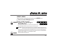
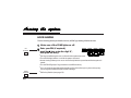
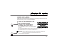
1
2
3
4
5
6
0
7
8
9
#
Panic
Part Number 5-051-264-01
Rev C
SYSTEMS, Inc.
Thank you for purchasing this C&K alarm system. Your system is one of the most powerful
and advanced alarm systems on the market today, designed to provide you with years of
reliable operation.
This manual explains how to operate your alarm system. Basic operating instructions are also
printed on the label inside your keypad(s) door.
If you have any questions or need help with
your alarm system, call:
___________________________________
(Alarm Company Name)
___________________________________
If you have monitoring questions or in cases
of accidental alarms, call:
___________________________________
(Monitoring Station Name)
______________________________________
When calling the monitoring company, know the following:
My Account Number is: ____________________
2
My Password is: __________________
Table of contents
Getting acquainted ............................................. 4-5
What the lights mean ......................................... 6-7
What the sounds mean ...................................... 8
Arming the system ............................................. 9-16
Bypassing zones .......................................... 14-15
Arming types ................................................ 16
Disarming the system ......................................... 17
After an alarm ..................................................... 18
Options ............................................................... 19-24
Changing a PIN ............................................ 20-21
Deleting a PIN .............................................. 21
Resetting smoke detectors .......................... 22
Door chime / Keypad tones.......................... 23-24
Testing your system ........................................... 25-27
Telephone trouble .............................................. 28
Smoke detector placement ................................. 29
Emergency evacuation ....................................... 30
Definitions........................................................... 31
Limitations of your alarm system ........................ 32
Keypad operations ............................................. 33-35
Test Procedure Index ......................................... 36
Zone description list ........................................... 38
FCC Notice......................................................... 39
Industry Canada ................................................. 40
3
What your alarm system is...
Your alarm system is made up of a control panel and several detection devices like motion sensors,
magnetic contacts, and so on. Specific areas of detection are called zones. Zones can be programmed to
have different characteristics. Some zones may be 24-hour zones, that is, they remain armed even when
the alarm system is off. Zones used for fire detection, for example, are always 24-hour zones. In addition,
some zones can be programmed to allow bypassing. When you bypass a zone, you temporarily remove
it from the alarm system. Always remember, however, that bypassed zones are not protected.
How your alarm system works...
When a detection device is triggered, the status of its zone goes from normal to FAULTED. If armed,
the control panel responds by reporting an alarm condition on site --- flashing keypad lights, sounding
bells --- and if programmed, by transmitting an alarm signal over the telephone wires to a central
monitoring station. The monitoring station then dispatches the appropriate authorities.
Some of your system's operations require you to enter your personal identification number (PIN) on the
keypad. These include ARMING and DISARMING.
Along with its many other features, your system can be programmed to ARM INSTANTLY or to ARM
WITH TIME DELAY (i.e., after giving you time to leave the premises).
4
Each alarm system in the 2300 family is designed to meet the specific needs of a variety of applications. The System
236 is designed for applications requiring protection of six zones.
Some of the available features of your alarm system are also optional, and will only be installed if appropriate for
your installation. In addition, some system features will require you to enter your personal identification number
(PIN).
As you read through this manual, watch for boxes like these:
OPTION
INSTALLED
PIN
REQUIRED
. If an optional feature has been installed in your system, its
OPTION INSTALLED box will be checked.
. If a feature of your system requires you to enter your personal
identification number, its PIN REQUIRED box will be checked.
5
ON
POWER
. AC power is being
ARM
. System is armed -
ZONES
. Zone is faulted while
supplied
protection is on
system is disarmed
OFF
. AC power failure system is using battery
. System is not armed protection is off
. Normal state; zone is not
faulted
FLASHING
. Battery is low; call your
service department
. System is armed with
delay zones converted to
instant zones
FLASHING SLOW -
. Zone is bypassed
. Zone is in trouble
FLASHING FAST -
. Zone is or was in alarm
6
ON
SERVICE
. Bell fuse failed
OFF
. Normal state
FLASHING
FLASHING SLOW -
. Watchdogreset
. Zone is in trouble (when
accompaniedbyslow
flashing zone light)
FLASHING FAST -
. Failedtocommunicate
POWER,
ARM, and
SERVICE
FLASHING SLOW -
. The POWER, ARM, and
SERVICE lights simultaneously flash (slowly) when
in the programming mode.
7
SOUND
2 beeps (confirmation tones)
5 beeps (error tones)
continuous tone, beeping fast for last ten seconds
continuous beeping, speeding up for last ten seconds
2secondbeep
chirping (1 second on, 4 seconds off)
continuoustone
pulsed tone (2 seconds on, 2 seconds off)
8
MEANING
. system armed or disarmed
. successful central station test or battery test
. wrongPINnumberentered
. invalidfunction
. unauthorizedcommandattempted
. error changing PIN number
. entrydelaytime
. exit delay time
. doorchime
. zone faulted during walk-test
. zone programmed for chirping bell or siren is in alarm
. zone programmed for steady bell or siren is in alarm
. circuit malfunction (trouble on supervised loops only)
. zone programmed for pulsed bell or siren is in alarm
TO ARM THE SYSTEM / AUTO HOME ARMING:
Make sure all the ZONE lights are off.
. Faulted zones must be cleared or bypassed before the system can be armed. For more
OPTION
INSTALLED
information, refer to the sectionsBypassing Zones andAfter An Alarm Occurs.
. If programmed, the red ZONE lights will automatically turn off after five minutes (as a
security measure). Pressing any key on the keypad will turn the ZONE lights back on.
PIN
REQUIRED
Enter your PIN and push the
# key.
. Your PIN number is four digits long.
. Don't pause for more than 5 seconds while entering the digits or the control panel will
reject your PIN number.
. If you make a mistake while entering your PIN number, the keypad will beep five times.
After the fifth beep, enter your PIN number again.
Make sure the red ARM light comes on.
. The keypad will beep twice to confirm that the system is armed.
9
Exit through any TIME DELAY DOOR within
OPTION
INSTALLED
seconds.
. The exit delay time can be programmed from 10 seconds to 150 seconds.
. If the EXIT PRE-ALARM option is installed, the keypad will beep slowly until 10 seconds
before the delay time expires, then rapidly for the last 10 seconds.
. Once the exit delay time has expired, the keypad will beep twice to confirm that the
system is armed.
OPTION
INSTALLED
TheAUTO HOME ARMINGoption enables the system to automatically
bypass interior zones if you arm the system but do not leave the premises.
The perimeter zones will be armed and the entry delay will remain intact.
With this option installed, arm the system (enter your PIN and push the # key).
. If you do not exit before the exit delay time expires, the system will automatically arm
perimeter zones and bypass interior zones.
. If you exit through an exit delay door, the system will automatically arm interior and
perimeter zones.
The rest of the ARMING THE SYSTEM section explains how to bypass zones before arming the system, as well as
certain arming options our installer can install. However, it's important for you to remember that no matter how your
system is programmed, you will always disarm it in the same way: enter your PIN, then push the # key.
10
INSTANT ARMING
Instant arming converts all time delayed zones toINSTANT zones.
Make sure all the ZONE lights are off.
PIN
REQUIRED
Enter your PIN (if required),
push the
key, enter the digit "7",
then push the # key.
7
. The keypad will beep twice to confirm that the system is armed.
. The red ARM light will flash while the system is instant armed.
CAUTION: When the system is instant armed, you will not be able to enter through any
perimeter door or walk through any protected area without setting off an alarm.
. Home Arming or bypassing interior zones will allow you to move about freely inside the
premises while the system is armed. Refer to the next three sections: HOME ARMING,
INSTANT HOME ARMING, and BYPASSING ZONES.
OPTION
INSTALLED
. Exit Delay Disable (see page 16).
11
HOME ARMING
Home arming arms perimeter zones, while bypassing interior zones.
Make sure all the ZONE lights are off.
PIN
REQUIRED
Enter your PIN (if required),
push the
key, enter the digit "4",
then push the # key.
4
. The keypad will beep twice to confirm that the system is armed.
. The red ARM light will be on while the system is armed.
. Home Arming allows you to move about freely inside the premises while the system is
armed.
. The red ZONE light(s) of bypassed zones will flash slowly.
. You can enter the premises without setting off an alarm through any time delay entry.
(Don't forget to disarm the system after entering!)
OPTION
INSTALLED
12
. Exit Delay Disable (see page 16).
INSTANT HOME ARMING
Instant home arming arms the perimeter zones and bypasses interior zones.
Entry time delays are converted to INSTANT.
Make sure all the ZONE lights are off.
PIN
REQUIRED
Enter your PIN (if required),
push the
key, enter the digit "7",
the digit "4", then push the # key.
. The keypad will beep twice to confirm that the system
7
4
OR
4
7
is armed.
. The red ARM light will flash while the perimeter zones are instant armed.
. The red ZONE light(s) of bypassed zones will flash slowly.
CAUTION: When the system is instant home armed, you will not be able to enter
through any perimeter door without setting off an alarm.
OPTION
INSTALLED
. Exit Delay Disable (see page 16).
13
BYPASSING ZONES
This procedure allows you to bypass one or more zones while your system is
DISARMED*.
NOTE:System programming determines which zones can be bypassed. To learn if a
zone can be bypassed, see the ZONE DESCRIPTION LIST on page 39.
PIN
REQUIRED
Enter your PIN (if required).
Push the
key, enter the digit "2", enter
the zone to be bypassed, then push the
# key.
2
ZONE #
. The ZONE light for the bypassed zone(s) will flash slowly.
*NOTE: Zones can be also be bypassed by remote programming. When remote
programming is used, the system can either be armed or disarmed.
14
. The procedures for adding a bypass and removing a bypass are identical.
To
remove a bypass: enter your PIN, push the key, enter the digit "2", enter the zone
from which the bypass is to be removed, then push the # key.
. When you have finished bypassing zones, arm the system by entering your PIN and
pushing the # key.
NOTE: Disarming your alarm system REMOVES all bypasses.
15
Your alarm system has been programmed for one of the following two arming types:
OPTION
INSTALLED
OPTION
INSTALLED
GOOF-PROOF ARMING
If any zone other than a 24-hour zone is faulted (open window, malfunctioning sensor, etc.), your system will not arm. You will not be able to arm the
system until the faulted zone is cleared or manually bypassed.
FORCE ARMING
Any zone (except for 24-hour zones) that is violated during the EXIT DELAY
time will automatically be bypassed until the system is disarmed.
Warning: bypassed zones are not protected.
OPTION
INSTALLED
16
EXIT DELAY DISABLE
If this option is installed, the exit delay will be eliminated when arming your
system using Instant Arming (page 11), Home Arming (page 12), or Instant
Home Arming (page 13).
TO DISARM THE SYSTEM:
Enter only through a TIME DELAY door.
OPTION
INSTALLED
PIN
REQUIRED
. If the ENTRY PRE-ALARM option is installed, the keypad will sound constantly until 10
seconds before the delay time expires (or the panel is disarmed), then beep rapidly for
the last 10 seconds.
Enter your PIN within
seconds and push the # key.
Make sure the red ARM light on the keypad goes off.
. If the ARM light does not go off, wait for the keypad to beep five times, then enter your
PIN again.
. The keypad will beep twice to confirm that the system has been disarmed.
. All bypasses are removed.
17
AFTER AN ALARM OCCURS:
PIN
REQUIRED
Enter your PIN and push the
# key.
. This will silence the bell/siren and disarm the system.
. The red ZONE lights on the keypad will flash fast to help you remember where the
violations occurred.
If this is a false alarm and no emergency response is needed, call
our central station IMMEDIATELY at
to
cancel the alarm.
. Write down the number of the faulted zones to help us service you.
Clear the alarm memory and red ZONE lights
by pushing the
key, entering the digit "1",
then pushing the # key.
18
1
OPTION
INSTALLED
24-HOUR MONITORING
With this option installed, your alarm system will transmit alarm signals to
our central station.
OPTION
INSTALLED
POLICE/PANIC KEY
When this option is installed, holding down the "7" and "9"
(PANIC) keys at the same time will trigger an alarm. The
keypad will beep twice to confirm the alarm condition.
9
7
PANIC
19
CHANGING A SYSTEM 236 USER PIN
User 1 can use his Master PIN to change the PINs of Users 1 - 6.
MASTER PIN
REQUIRED
Enter your master PIN, push
the key, enter the digit "0", then
push the # key.
0
. The POWER, SERVICE, and ARM lights will slowly flash.
Enter the User number (1 - 6), and push
the # key.
Enter that User's new PIN and push
the # key.
. The new PIN must be four digits long.
20
USER #
Enter the new PIN again and push
the # key.
. If the new PIN is accepted, the keypad will beep twice. If you make a mistake while
programming, or if the system rejects the new PIN, the keypad will beep five times. Try
again.
. If no key is pressed for 5 minutes, the system will automatically exit the programming
mode.
Exit the programming mode by pushing the
key, then the # key.
Make sure the new PIN works.
DELETING A SYSTEM 236 USER PIN
User 1 can use his Master PIN to delete the PINs of Users 2 - 6. Follow
steps 1 through 4 for Changing a User PIN. In steps 3 and 4 enter four zeros
in place of a new PIN.
21
OPTION
INSTALLED
RESETTING SMOKE DETECTORS
When a smoke detector is triggered, the red ZONE light of the zone where it's
located will come on, and the bell/siren will sound.
Before you do anything else, evacuate the building. Don't go back
inside until your sure it's safe. When it's safe to do so, you can reset the
smoke detectors by doing the following:
Push the
key, enter the digit "6",
the digit "2", and push the # key.
OPTION
INSTALLED
6
2
STANDBY BATTERY
Should there be a loss of AC power, the green POWER light on the keypad
will go out, and your alarm system will switch to its standby battery. If an AC
power failure lasts for more than 15 minutes, the system will send a signal to
the central station (if programmed to do so).
. The standby battery should be replaced every three to five years with a rechargeable 12 V 6.5 Ah sealed lead-acid battery (such as C&K Model 1265).
22
OPTION
INSTALLED
DOOR CHIME
When this option is installed, the keypad will beep for two seconds each time
a designated zone is faulted.
To turn the door chime on and off (for all keypads installed):
Push the
key, enter the digit "5",
then push the # key.
5
KEYPAD TONE DISABLE
You can disable the sounds the keypad makes for a variety of functions. These
functions include: keypad feedback (the keypad beeps everytime you press a key),
EXIT PRE-ALARM tone (exit delay countdown), ENTRY PRE-ALARM tone (entry time
delay countdown), and CONFIRMATION/ERROR tones (see page 6).
To turn the keypad feedback on and off:
Push the
key, enter the digit "5",
the digit "1", and push the # key.
5
1
23
KEYPAD TONE DISABLE (Continued)
To turn the ENTRY/EXIT PRE-ALARM tones (entry/exit delay countdown) on
and off:
Push the
key, enter the digit "5",
5
2
the digit "2", and push the # key.
To turn the CONFIRMATION/ERROR tones on
and off:
Push the
key, enter the digit "5",
the digit "4", and push the # key.
24
5
4
LOCAL SYSTEM TEST
This option allows on-site testing of each zone in your system.
To initiate the SYSTEM TEST:
Enter your PIN (if required),
push the
key, enter the digit "6",
the digit "0", then push the # key.
PIN
REQUIRED
. Once the keypad lights go out, the system will be
.
6
0
ready for testing. Walk through the areas protected
by motion sensors; open and close protected doors and windows. Each time a zone is
faulted, its corresponding red ZONE light on the keypad will begin flashing, and the
keypad will chime.
To exit the system test, push any key.
WARNING: Your alarm system will not report alarms during the LOCAL SYSTEM TEST.
25
OPTION
INSTALLED
STANDBY BATTERY TEST
Your alarm system can be programmed to automatically test its standby
battery every 24 hours. During the test, AC power is turned off in order to
monitor the battery under load.
. To manually test the standby battery, push the
key, enter the digit "6", the digit "4", then push the
# key.
6
4
. The standby battery test takes 2 minutes. During the test, the POWER light will be off.
. If the battery is okay, the keypad will beep twice.
If the battery is low or dead, the POWER light will flash, and the keypad will beep five
times.
OPTION
INSTALLED
PIN
REQUIRED
BELL/SIREN TEST
3
To test the bells/sirens in your security system:
Enter your PIN (if required), push the key, enter the digit "6", the digit "3",
then push the # key.
. The bell/siren and keypads will sound for 3 seconds.
26
6
OPTION
INSTALLED
CENTRAL STATION TEST
This option tests the reporting capability of your system by sending a test
message to the central station. Weekends are the best time for the CENTRAL
STATION TEST. To schedule one, call our central station at:
CENTRAL STATION
PIN
REQUIRED
To initiate the CENTRAL STATION TEST:
Enter your PIN (if required),
push the
key, enter the digit "6",
the digit "1", then push the # key.
. If the test message was successfully transmitted to
6
1
the central station, the keypad will beep twice.
. If the test message was not successfully transmitted to the central station, the
keypad will beep five times, and the SERVICE light will flash fast. Call our Service
Department for assistance.
27
IF YOU HAVE TELEPHONE TROUBLE:
First, unplug the control panel from its telephone jack to determine if the
alarm system is causing the trouble.
The phone jack is located
.
If the trouble goes away when you unplug the control, callus for service.
If you still have telephone trouble after unplugging the alarm system, plug the
system back in, then call yourtelephone company.
NOTE: If your telephone system is serviced, make sure to test your alarm system to
insure that it has not been disconnected from the telephone network.
28
We subscribe to the recommendations for the number and placement of smoke and/or heat detectors found in the
National Fire Protection Association'sStandard #72, Chapter 2(N.F.P.A. Batterymarch Park, Quincy, MA 02269).
For the best early warning, fire detection devices should be installed in all rooms and areas of the premises. A smoke
detector should be installed in each separate sleeping area, in the vicinity of bedrooms. (In new construction, a smoke
detector shall be installed in each separate sleeping room.) Heat or smoke detectors should be installed in living rooms,
closets, utility and storage rooms, basements, and attached garages.
Place detector near all sleeping areas
DINING
ROOM
Best residential detector placement between
bedrooms and the rest of the house
KITCHEN
FAMILY
ROOM
LIVING ROOM
BEDROOM
BEDROOM
KITCHEN
DINING
ROOM
BEDROOM
BEDROOM
Place detectors near
top of stairwells
BEDROOM
BEDROOM
= SMOKE DETECTOR
BEDROOM
LIVING ROOM
C
= CONTROL
S
= SOUNDER
K
= KEYPAD
BEDROOM
BEDROOM
BASEMENT
29
Every household should establish and regularly practice an escape plan in the event of a fire. The following steps,
recommended by the National Fire Protection Association, can be used as a guide in developing your own emergency
plan.
. Plan on your detector or alarm system sounders waking all
occupants.
. Determinetwomeansofescapefromeachroom,especially
. Establish a meeting place outdoors, away from the house, where
everyone can gather and account for those missing. Choose
someone to notify the authorities. Choose someone to ensure that
nobody returns to the house. Many die going back inside.
the bedrooms, since most fires occur at night when everyone is
asleep. One escape path should lead to a door that permits normal
exit from the house. The other may be an easily opened window
(used if the primary escape path is blocked).
. Escape quickly. But don't panic.
. Before you open a door, check to see if it's hot. If it is hot, don't
that can be used for escape. Indicate escape routes for each room
(see examples below). Post copies of the sketch in each room.
Remember to keep all escape routes free from obstruction.
. When moving through a smoky area, stay as close to the floor as
. Sketch a floor plan, showing doors, windows, stairs, and rooftops
. Keep all bedroom doors shut while the occupants are asleep.
open it. Use an alternate escape route. Even if the door is cool,
use your shoulder to open it cautiously. Be ready to slam it closed if
heat or smoke rushes in.
possible. Crawl and hold your breath.
This will prevent deadly smoke from entering the rooms while you
escape.
KITCHEN
DINING
FAMILY
ROOM
BEDROOM
SAMPLE
SECOND FLOOR
SAMPLE
FIRST FLOOR
BEDROOM
LAUNDRY
30
BATH
LIVING ROOM
BATH
BEDROOM
ALARM
A condition that occurs when the detection devices in a zone are
triggered after the system is armed.
ALARM MEMORY
Alarm conditions are stored in memory until cleared.
BYPASS
To take a zone out of the circuit. Bypassing malfunctioning zones
allows the rest of the system to be armed. Bypassing interior zones
allows freedom of movement inside the premises, while leaving outer
zones armed. Bypassed zones are not protected.
CENTRAL STATION
The office that the alarm system calls when there is an alarm. Signals
sent to the central station contain information about the nature of the
alarm condition, allowing the dispatcher on duty to appropriately
respond.
ENTRY DELAY
The time you have to enter the premises through a designated DELAY
DOOR and disarm the panel (before an alarm occurs). The delay
time is programmable from 10 seconds to 150 seconds. [Note: if this
option is programmed forLong Delay, the delay time will be doubled
(from 20 to 300 seconds).]
EXIT DELAY
Once the system is armed, the time you have to exit the premises
through a DELAY DOOR (before an alarm occurs). The delay time is
programmable from 10 seconds to 150 seconds.
FAULT
A trouble condition that occurs when the detection devices in a zone
are violated or mafunctioning while the system is disarmed.
GRADE "A"
System that provides supervision of the transmitter or initiating
devices (i.e., detection devices and wiring).
PERSONAL IDENTIFICATION NUMBER (PIN)
The combination used to arm and disarm the control panel, and to
access any of the special functions that require a combination. PIN
numbers must be four digits long.
ZONE
One of the protected areas in your premises.
24-HOUR ZONE
A zone that is always active, whether the system itself is armed or
disarmed. FIRE, POLICE, and EMERGENCY zones are usually
24-hour zones. Alarm conditions on these zones are cleared by
entering a valid PIN number.
31
THE LIMITATIONS OF YOUR ALARM SYSTEM
While your alarm system is reliable and sophisticated, it does not offer guaranteed protection against burglary or fire. Any alarm system, whether
commercial or residential, is subject to compromise or failure-to-warn for a variety of reasons. These include:
Intruders may gain access through unprotected openings or have the technical sophistication to bypass an alarm sensor or disconnect an alarm
warningdevice.
Intrusion detectors, smoke detectors, and many other detection devices will not operate without power. Devices powered by AC will not work if
their AC power supply is off for any reason and their back-up batteries are missing, dead, or improperly installed.
Alarm warning devices such as sirens, bells, and horns may not alert people or wake up sleepers if they are located on the other side of closed
or partly closed doors. If warning devices are on a different level of the residence from the bedrooms, they are less likely to waken or alert
people inside the bedrooms.
Telephone lines needed to transmit alarm signals from a premises to a central monitoring station may be out of service, and are subject to
compromise by sophisticated means of attack.
Smoke detectors used in conjunction with the alarm system may not sense fires that start where smoke cannot reach the detectors, such as in
chimneys, walls or roofs, or on the other side of closed doors. Smoke detectors also may not sense a fire on another level of the residence or
building. A second floor detector, for example, may not sense a first floor or basement fire. Finally, smoke detectors have sensing limitations.
No smoke detector can sense every kind of fire every time. In general, detectors may not always warn you about fires caused by carelessness
and safety hazards, like smoking in bed, violent explosions, escaping gas, improper storage of flammable materials, overloaded electrical
circuits, children playing with matches, arson, etc.
The most common cause of an alarm system not functioning properly when an intrusion or fire occurs isinadequate maintenance. Your alarm
system should be tested weekly to make sure all detection devices are operating properly. Your control panel and keypads should be tested as
well.
Installing an alarm system may make you eligible for lower insurance rates, but an alarm system is not a substitute for insurance.
Homeowners, property owners, and renters should continue to insure their lives and property.
.
.
.
.
.
.
.
32
For your convenience, the following is a list of the keypad operations discussed in these instructions.
KEYS
FUNCTIONS
Arms and Disarms the system
PERSONAL IDENDIFICATION
NUMBER (PIN)
0
Programs new user PINs (master PIN required).
1
Clears the alarm memory
Bypasses individual zones (PIN may be required).
2
ZONE #
Arms the system with interior zones bypassed (PIN may be required).
4
4
5
7
Converts Entry time delay zones to INSTANT (if programmed to do
so), and arms perimeter zones, while bypassing interior zones (PIN
may be required). Refer to Instant Home Arming on page 13.
Turns the door chime on/off (on all keypads).
33
KEYS
34
FUNCTIONS
5
1
Turns the audible keypad feedback on/off.
5
2
Turns the Entry/Exit Pre-Alarm tones on/off.
5
4
Turns the Error tones on/off.
6
0
Initiates the Local System Test (PIN may be required).
6
1
Initiates the Central Station Test (PIN may be required).
6
2
Resets Smoke Detectors.
6
3
Initiates the Bell/Siren Test (PIN may be required).
KEYS
6
FUNCTIONS
4
Converts all time delay zones to INSTANT and arms the system (PIN
may be required).
7
7
7
9
Initiates the Standby Battery Test.
4
Converts Entry time delay zones to INSTANT (if programmed to do
so), and arms perimeter zones, while bypassing interior zones (PIN
may be required). Refer to Instant Home Arming on page 13.
Press both keys simultaneously to activate an alarm.
35
As required by UL Standard 1023, your alarm system is a Grade "A" system
(see definition on page 31).
Alarm system malfunctions and failures are caused most often by
INADEQUATE MAINTENANCE.
Your alarm system should be tested weekly to make sure that all detection
devices are working properly. In addition, if your system is being monitored,
you should periodically test its ability to transmit signals to our central station.
These tests should be performed weekly:
. LOCAL SYSTEM TEST: Enter PIN (if required), then
. CENTRAL STATION TEST: Enter PIN (if required), then
. BELL/SIREN TEST: Enter PIN (if required), then
. STANDBY BATTERY TEST:
Refer to pages 25 - 27 for further information on test procedures.
36
6
0
6
1
6
3
6
4
Notes
37
ZONE
LOCATION
B Y PA S S
YES
1
2
3
4
5
6
38
NO
FCC NOTICE
WARNING: This device is intended to be installed by a professional alarm installer.
The user shall be cautioned that changes or modifications not expressly approved by C&K SYSTEMS could void the user’s authority to operate the equipment.
FCC Rules PART 15
This equipment has been tested and found to comply with the limits for Class B digital devices, pursuant to Part 15 of the FCC Rules. These limits are designed to provide
reasonable protection against harmful interference in a residential installation.
This equipment generates, uses, and can radiate radio frequency energy, and if not installed and used in accordance with the instructions, may cause harmful interference
to radio communications. However, there is no guarantee that interference will not occur in a particular installation.
If this equipment does cause harmful interference to radio or television reception, which can be determined by turning the
equipment off and on, the user is encouraged to try to correct the interference by one or more of the following measures:
Reorient the radio/television antenna.
Connect the AC transformer to a different outlet so that the control panel and radio/television are on different branch circuits.
Relocate the control panel with respect to the radio/television.
Consult the dealer or an experienced radio/television technician for help.
FCC Rules PART 68
This equipment has been tested and found to comply with Part 68 of the FCC Rules. On the left outside panel of the can is a label that contains the FCC registration number
and the Ringer Equivalence Number (REN) for this equipment. This information must be provided to your telephone company, if requested. The REN may be used to
determine the maximum number of devices which may be connected to your telephone line and still have all devices ring properly when your number is called. The
maximum sum of all devices should not exceed 5. This number may be different in your area. Contact your local telephone company to determine the maximum REN
for your calling area.
Should you experience trouble with the telephone lines, disconnect the panel from the line to determine the source of the trouble. If it is determined that the control panel
is malfunctioning, discontinue its use until the malfunction has been corrected. Any repairs or alterations made by the user to this equipment, or equipment malfunctions,
may give the telephone company cause to request the user to disconnect the equipment. Repairs to this equipment should be made by an authorized agent of C&K
SYSTEMS, Inc. Contact your local alarm installation company for service.
Should this equipment cause harm to the telephone system, the telephone company may temporarily discontinue your service. If possible, they will provide you with
advance notice. Otherwise they will notify you as soon as possible. The telephone company will also advise you of changes in its facilities, equipment, operations or
procedures which could affect the operation of your equipment, allowing you the opportunity to maintain uninterrupted service. You will also be advised of your right to
file a complaint with the FCC.
This device must not be used on party lines or coin operated phone lines.
39
Industry Canada
NOTICE: The Canadian Department of Communications label identifies certified equipment. This certification means that the equipment meets certain telecommunications network protective, operational and safety requirements. Industry Canada does not guarantee the equipment will operate to the user’s satisfaction.
Before installing this equipment, users should ensure that it is permissible to be connected to the facilities of the local telecommunications company. The equipment must
also be installed using an acceptable method of connection. In some cases, the company’s inside wiring associated with a single line individual service may be extended
by means of a certified connector assembly (telephone extension cord). The customer should be aware that compliance with the above conditions may not prevent
degradation of service in some situations.
Should you experience trouble with the telephone lines, disconnect the panel from the line to determine the source of the trouble. If it is determined that the control panel
is malfunctioning, discontinue its use until the malfunction has been corrected. Any repairs or alterations made by the user to this equipment, or equipment malfunctions,
may give the telephone company cause to request the user to disconnect the equipment. Repairs to this equipment should be made by an authorized agent of C&K
SYSTEMS, Inc. Contact your local alarm installation company for service.
Users should ensure for their own protection that the electrical ground connections of the power utility, telephone lines and internal metallic water pipe system, if present,
are connected together. This precaution may be particularly important in rural areas.
Caution: Users should not attempt to make such connections themselves, but should contact the appropriate electric inspection authority, or electrician, as appropriate.
The Load Number (LN) assigned to each terminal device denotes the percentage of the total load to be connected to a telephone loop which is used by the device, to
prevent overloading. The termination on a loop may consist of any combination of devices subject only to the requirement that the total of the Load Numbers of all devices
does not exceed 100.
This digital apparatus does not exceed the Class B limits for radio noise emissions from digital apparatus set out in the Radio Interference Regulations of the Industry
Canada.
Le présent appariel numérique n’émet pas de bruits radioélectriques dépassant les limites applicables aux appareils numériques de la Class B prescrites dans le
Règlement sur le brouillage radioélectriques édicté par Industrie Canada.
Printed in Hong Kong
5-051-264-01 Rev C
40
C&K is a registered trademark of C&K
Components, Inc.
Copyright 1995 C&K SYSTEMS, Inc.
All Rights Reserved
SYSTEMS, Inc.