1
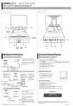
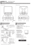
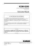
KD-2306
Non-contact Displacement Measuring
System User’s Manual
This apparatus, when installed and operated per the manufacturer’s recommendations,
conforms with the protection requirements of EC Council Directive 89/336/EEC on the
approximation of the laws of the member states relating to Electromagnetic Compatibility. Refer
to the KD-2306 Declaration of Conformity or contact Kaman Precision Products for details.
Copyright © 2014
PART NO: 860512-001
Last Revised: 11/26/2014
Kaman Precision Products
A Division of Kaman Aerospace Corporation
217 Smith Street
Middletown, CT 06457
www.kamansensors.com
Table of Contents
Part 1 – KD-2306 Description.................................................................. 3
Part 2 - Connecting the KD-2306 ............................................................ 4
Part 3 – KD-2306 Outputs ....................................................................... 5
3.1 Single Ended Voltage Output: ....................................................... 5
3.2 Differential Voltage Output:............................................................ 6
3.3 4-20 mA Current Output: ............................................................... 7
Part 4 - Calibrating the KD-2306 ............................................................. 7
4.1 Calibration Controls ....................................................................... 7
4.1.1 MIN (Zero) Controls ................................................................... 8
4.1.2 MID (Gain) Controls .................................................................... 8
4.1.3 MAX (Linearity) Controls............................................................. 9
4.2 Calibration Methods ....................................................................... 9
4.3 Calibration Procedures ................................................................ 10
4.3.1 Full Scale Calibration Procedure (Voltage)............................... 10
4.3.2 Full Scale Calibration Procedure (Current) ............................... 11
4.3.3 Bipolar Voltage Output Calibration Procedure .......................... 12
4.3.4 Alternate Bipolar Voltage Output Calibration ............................ 13
4.3.5 High Accuracy Band Voltage Calibration .................................. 14
Part 5 - Synchronizing Multiple KD-2306 Systems................................ 16
Part 6 - System Modifications................................................................ 17
6.1 Temperature Compensation ........................................................ 17
6.2 Bridge Card.................................................................................. 17
6.3 Target Material............................................................................. 18
6.4 Sensor Cable Length ................................................................... 18
Appendix A – Standard Sensor Ranges & Offsets ................................ 19
www.kamansensors.com
PART NO: 860512-001
Last Revised: 11/26/2014
2
Part 1 – KD-2306 Description
Kaman Precision Products’ Model KD-2306 is a non-contact, linear, analog displacement measuring
system. The system operates on a traditional inductive bridge circuit. This easy-to-use, versatile
system can be utilized for precision static and dynamic measurements of conductive targets.
The sensor coil makes up one or two legs (depending on single or dual coil sensor) of a balanced
bridge network. As the target changes position within the sensor field, the bridge network senses
impedance changes in the sensor coil. These changes are converted to an analog voltage or
current signal directly proportional to target displacement.
The KD-2306 system consists of two subassemblies: sensor with either integral or removable
cable, and signal conditioning electronics module in a DIN mounting enclosure.
The system is preconfigured at the factory for a particular sensor, cable length, target material,
and calibrated measuring range.
The KD-2306 is a lead-free, RoHS compliant, CE Marked design. To maintain the CE Mark, the
following precautions are necessary:
1) I/O cable length is limited to a maximum of 30 m (100 ft).
2) The electronics are supplied with a cover over the calibration potentiometers on the front
panel to protect the circuit from damage due to Electrostatic Discharge (ESD). Removal
of the cover makes the unit susceptible to ESD damage and it must be handled
accordingly.
3) The electronics power and I/O must be isolated from the AC Mains and not subject to
transient over-voltages. That is, it must be powered by a D.C. secondary circuit that is
reliably grounded, capacitively- filtered, with peak-to-peak ripple less than 10% of the
D.C. component.
www.kamansensors.com
PART NO: 860512-001
Last Revised: 11/26/2014
3
Part 2 - Connecting the KD-2306
CAUTION:
Maximum terminal screw torque is 0.8 N-m (7.0 inch-pounds).
The sensor is always connected to the twin BNC connector on the front panel. All other input,
output, and synchronization connections to the KD-2306 are at the terminals as noted in the table
below. More details on these connections are contained in subsequent sections of this manual.
1
2
3
4
5
6
7
8
COARSE
1
2
3
4
5
6
7
8
9
10
11
12
13
14
15
16
FINE
MAX
MID
MIN
SENSOR
KAMAN
9 10 11 12
13 14 15 16
Voltage Output +
4-20 mA Output High
Ground
Synchronization In
Voltage Output 4-20 mA Output Low
Ground
Earth Ground
NC
Ground
Voltage Input +15 to 30 VDC
Ground
Ground
Ground
Synchronization Out
Ground
Ground
+V in
Input power is connected to terminals 11 and 12 as shown. A good quality linear or switching supply
with an output of +15 to 30 VDC and 150 mA is recommended for best (lowest noise) performance.
Consult the Accessories Data Sheet for recommended power supply options.
www.kamansensors.com
PART NO: 860512-001
Last Revised: 11/26/2014
4
Part 3 – KD-2306 Outputs
The KD-2306 system has three different analog outputs. All three outputs are always present,
but only one is calibrated. Adjustment of the calibration controls for one of these outputs will drive
the other outputs out of calibration.
Voltage outputs have a maximum single ended span of 10 VDC. Unless otherwise specified, the
system will be factory calibrated for 0-10 VDC over the full measuring range of the sensor. Other
typical outputs are 0-5 and ±5 VDC. The KD-2306 output may also be adjusted to provide a
specific sensitivity, such as 1 V/mm.
3.1 Single Ended Voltage Output:
Unless otherwise specified, this output will be calibrated for 0-10 VDC output at the factory. For
single ended voltage output, connect V+ to terminal 1 and signal return to terminal 3 as shown.
1
2
3
4
5
6
7
8
COARSE
Ground
FINE
MAX
+ V out
MID
MIN
SENSOR
KAMAN
9 10 11 12
13 14 15 16
www.kamansensors.com
PART NO: 860512-001
Last Revised: 11/26/2014
5
3.2 Differential Voltage Output:
This is a true differential output. – V out is not Ground, but a voltage. This output is used to provide a
balanced signal for reduction of common-mode interference (noise picked up equally by both leads).
It can also eliminate a common ground between the KD-2306 and remote equipment in order to
reduce ground loops. It has a maximum span of 10 VDC. For differential voltage output, connect V+
to terminal 1 and V- to terminal 5 as shown.
1
2
3
4
5
6
7
8
COARSE
FINE
MAX
+ V out
MID
MIN
Gnd
- V out
SENSOR
KAMAN
9 10 11 12
13 14 15 16
www.kamansensors.com
PART NO: 860512-001
Last Revised: 11/26/2014
6
3.3 4-20 mA Current Output:
For industrial applications or long output cable lengths, a 4–20 mA current output may be used. For
current output, connect the – lead to terminal 2 and + lead to terminal 6 as shown. The loop is
powered by the KD-2306.
1
2
3
4
5
6
7
8
COARSE
FINE
MAX
MID
MIN
SENSOR
+
4-20mA Receiver
(250 ohm typical)
KAMAN
9 10 11 12
13 14 15 16
NOTE ABOUT CURRENT OUTPUT: Early versions of the KD-2306 (i.e. serial numbers beginning
with “S08”) require a separate loop supply. The loop supply must have adequate voltage to deliver
20 mA to the load. If the voltage is too low for the load resistance, 20 mA will not be achieved.
Part 4 - Calibrating the KD-2306
4.1 Calibration Controls
There are 6 controls to calibrate the KD-2306, all located on the front panel and accessible by the
narrow end of an adjustment tool. The controls are: Coarse & Fine Linearity, Coarse & Fine Gain,
Coarse & Fine Zero. Coarse controls will give you a large change in adjustment; Fine controls will
give you a smaller change in output and are used in final adjustments.
The calibration controls have been relabeled in newer versions of the KD-2306. Instead of Offset,
Gain and Linearity, the terms MIN, MID, and MAX are used to be more descriptive of their functions
(i.e. effect on calibration curve)
www.kamansensors.com
PART NO: 860512-001
Last Revised: 11/26/2014
7
4.1.1 MIN (Zero) Controls
+OUTPUT
The Min Controls (Coarse & Fine) set the electrical zero point. This control is also referred to as the
“electrical offset. As illustrated in the diagram below, the Min controls adjust the point at which output
intercepts the x-axis.
ZERO
INI TIAL CALIBRATI ON
ZERO
AFTER CONTROL
ADJUSTMENT
-OUTPUT
TARGET
DISPLACEMENT
After calibration, the Zero controls can be used to shift system output anywhere from 40-60% below
the x-axis, depending on sensor, sensor mounting and gain. This feature is useful in applications
where you need a ± deviation from a standard, or when a bipolar output is required.
The Zero controls can be utilized for final positioning of the output after installing the sensor in it a
mechanical fixture. In general, limit the amount of adjustment to tens of milli-volts of output
adjustment to avoid altering the factory calibration.
4.1.2 MID (Gain) Controls
INCREASED GAIN
INITIAL CALIBRATION
DECREASED GAIN
-OUTPUT
+OUTPUT
The Mid controls (Coarse & Fine) affect the change in output of a system in volts due to a given
change in displacement. The Gain control sets the sensitivity or scale factor or Volts/mil (or mm).
The diagram shows how the slope of the output curve changes as gain is increased and decreased.
www.kamansensors.com
PART NO: 860512-001
Last Revised: 11/26/2014
8
4.1.3 MAX (Linearity) Controls
The Coarse and Fine Max controls affect the shape of the system output curve. The closer the output
is to a straight line, the more accurate your measurement readings. When calibrating, adjustment of
the Max controls interacts with the Gain and Zero controls. The Max controls are primarily used to
swing the full-scale endpoint. Due to the effect of the log amp, it will have some effect on the mid and
less effect on the min.
4.2 Calibration Methods
The KD-2306 has three possible calibration methods. The current output can only be calibrated for 4
to 20 mA, so there is no possible bipolar calibration.
Full Scale:
(Voltage Out) Output from 0 VDC to some maximum value.
(Current Out) Output from 4 mA to 20 mA
Bipolar:
Negative output for first half of range; positive output for second half.
High Accuracy Band: Increased linearity by using only part of the full-scale Measuring range
(Voltage or Current).
Depending on the application, select one of three procedures outlined above to calibrate a system.
Before calibration, we recommend that you become familiar with the following information to ensure
that you have made the necessary considerations regarding your particular application.
Full Scale Calibration
VDC
With a thorough knowledge of calibration variables and accurate application of the calibration
procedures described in the following pages, you can achieve optimum results. Deviations or
shortcuts can result in operator-induced errors and may complicate rather than solve measurement
problems.
offset
Bipolar Output Calibration
VDC
DISPLACEMENT
offset
High Accuracy Band
Calibration
VDC
DISPLACEMENT
offset
CALIBRATED
RANGE
DISPLACEMENT
www.kamansensors.com
PART NO: 860512-001
Last Revised: 11/26/2014
9
4.3 Calibration Procedures
Here are some general comments that are applicable to all calibration produces:
1. Mechanical positioning of the sensor must be performed accurately using a calibrated
micrometer fixture, precision spacers, or other dimensional standard.
2. A sample of the actual material to be measured by the system must be used as a calibration
target. Conductivity of the measured material affects system performance.
3. An inductive sensor always has an offset between the sensor face and start of its measuring
range. The offset serves two purposes a) It prevents mechanical damage caused by the
target striking the sensor face. b) It removes a very non-linear part of sensor output from the
measuring range making calibration easier, and performance much more linear. In general,
the offset is approximately 10 – 20% of the specified range.
4. Select the calibration procedure that is best for the application. Select the proper offset
distance, full-scale range, and desired voltage output. Calculate the midscale range and
output.
4.3.1 Full Scale Calibration Procedure (Voltage)
Full-scale calibration produces an output voltage that varies from 0 Vdc when the target is closest to
the sensor (plus offset) to some maximum positive voltage when the target is farthest from the
sensor.
For Single-Ended Output, monitor the voltage between terminals 1 & 3. Note that for the SingleEnded Output, terminal 3 is GND
VDC
For Differential Output, monitor the voltage between terminals 1 & 5. Both terminals 1 & 5 contain
voltage and cannot be grounded without causing erroneous readings and possible system failure.
Full Scale Calibration
offset
0
DISPLACEMENT
1. Install the sensor in the calibration or application fixture at the offset distance from the target.
2. Position the target using the micrometer fixture or spacers so that the total distance between
the sensor and target is equal to the specified full-scale displacement for that sensor, plus
offset.
www.kamansensors.com
PART NO: 860512-001
Last Revised: 11/26/2014
10
3. Adjust the MID (Gain) controls so that system output equals the desired full-scale output
voltage.
4. Reposition the target to minimum displacement (i.e. offset). Adjust the MIN (Zero) controls
until the output voltage reads 0 VDC.
5. Reposition the target to mid-scale plus offset and adjust the MID (Gain) controls until the
output voltage reads exactly half of the full-scale value.
6. Reposition the target to full-scale displacement, plus offset. Read the output voltage and
note the difference between the actual reading and the desired reading. Adjust the MAX
(Linearity) controls until the output reads the desired voltage level, then continue past the
desired reading by an amount equal to the first difference you noted. This technique is called
100% oversetting and is used to reduce the number of iterations needed to calibrate the
system. For example, if the output reads 9.5 volts and the desired reading is 10.0, adjust the
MAX (Linearity) controls until the output reads 10.5.
7.
Repeat Steps 4 through 6 as many times as necessary until the desired output voltage at
each point is obtained without additional adjustment.
4.3.2 Full Scale Calibration Procedure (Current)
Full Scale Calibration for the Current (4-20mA) output is similar to voltage calibration. This procedure
requires a current meter or multimeter with a current range. Typical connections for current
calibration are shown below:
1
2
3
4
5
6
7
8
COARSE
FINE
MAX
Load
250 ohm
(Typical)
MID
MIN
SENSOR
KAMAN
-
+
Current Meter
9 10 11 12
13 14 15 16
www.kamansensors.com
PART NO: 860512-001
Last Revised: 11/26/2014
11
1
Install the sensor in the calibration or application fixture at the offset distance
2
Position the target using the micrometer fixture or spacers so that the total distance between
the sensor and target is equal to the specified full-scale displacement for that sensor, plus
offset.
3
Adjust the MID (Gain) controls so that system output equals 20 mA
4
Reposition the target to minimum displacement (i.e. offset). Adjust the MIN (Zero) controls
until the output is 4 mA.
5
Reposition the target to mid-scale plus offset and adjust the MID (Gain) controls until the
output voltage reads 12 mA.
6
Reposition the target to full-scale displacement, plus offset. Read the current output and note
the difference between the actual reading and the desired reading. Adjust the MAX
(Linearity) controls until the output reads the desired 20 mA.
NOTE: The oversetting technique described in previous sections may not work with the 4-20
mA output due to lack of “headroom” above 20 mA.
7
Repeat Steps 4 through 6 as many times as necessary until the desired output at each point
is obtained without additional adjustment.
4.3.3 Bipolar Voltage Output Calibration Procedure
Bipolar Output Calibration
VDC
When you use this calibration procedure, output voltage will range from a negative voltage for the first
half of your measuring range to a positive output for the second half of the range.
offset
DISPLACEMENT
Use this method when your application requires a positive and negative output deviation from some
nominal value, in this case, 0 VDC. Bipolar calibration also provides maximum output sensitivity. (An
alternate technique is listed in the next section that will provide bipolar output, but not maximum
sensitivity).
In a bipolar calibration, clockwise rotation of the MIN (Zero) controls cause output to go more positive;
whereas, clockwise rotation of the MID (Gain) controls increases gain more negatively in the lower
half of the range and more positively in the upper half. Because of this, you will adjust the MID (Gain)
controls when the target is closest to the sensor and adjust the MIN (Zero) controls at the mid-scale
position.
www.kamansensors.com
PART NO: 860512-001
Last Revised: 11/26/2014
12
1.
Install the sensor in the calibration or application fixture at the offset distance.
2.
Position the target using the micrometer fixture or spacers so that the total distance between
the sensor and target is equal to the specified full-scale displacement for that sensor, plus
offset.
3.
Adjust the MAX (Linearity) controls until the output is equal to the desired full-scale reading.
4.
Reposition the target so that it is at mid-scale (plus offset) and adjust the MIN (Zero) controls
until the output reads zero.
5.
Reposition the target to minimum displacement (i.e. offset) and adjust the MID (Gain)
controls until output reads the desired negative output voltage.
6.
Reposition the target to full-scale displacement, plus offset. Read the output voltage and
note the difference between the actual reading and the desired reading. Adjust the MAX
(Linearity) controls until the output reads the desired voltage level, then continue past the
desired reading by an amount equal to the first difference you noted. This technique is
called 100% oversetting and is used to reduce the number of iterations needed to calibrate
the system.
7.
Repeat Steps 4 through 6 as many times as necessary until the desired output voltage at
each point obtained without additional adjustment.
4.3.4 Alternate Bipolar Voltage Output Calibration
You may not be able to achieve maximum sensitivity using this technique. This method may be
preferred if the maximum voltage does not exceed +10 VDC.
1. Use the Full-Scale procedure in section 4.3.1 to calibrate the system initially from 0 VDC to
the desired maximum.
2. Position the target at mid-scale and adjust the MIN (Zero) control counterclockwise until
output reads 0 VDC.
3. Check the two ends, the points closest and farthest from the sensor, to verify they equal
minus and plus one half of the original full-scale output voltage. For example, if your original
full-scale voltage was 0-4 VDC, it should now be -2 to +2.
In theory, adjusting the (MID) Zero controls in this technique should not affect sensitivity or linearity.
In practice, however, you may see a very slight change indicated by voltage readings other than
minus and plus one-half full scale. You may then choose to use the primary bipolar technique to finetune the calibration.
www.kamansensors.com
PART NO: 860512-001
Last Revised: 11/26/2014
13
VDC
4.3.5 High Accuracy Band Voltage Calibration
High Accuracy Band
Calibration
offset
CALIBRATED
RANGE
0
DISPLACEMENT
This procedure is used to monitor changes in position that are less than the specified linear
measuring range of your sensor, or when you are interested in increased accuracy over a smaller
range and not concerned about high accuracy outside of that range.
The high accuracy band procedure maximizes the linearity of output within a calibrated span. The
sensor installed in your system has a specified linear measuring range that defines system
performance characteristics, such as linearity, resolution and long-term stability.
Maximum linearity is centered on the mid-point of the sensor’s specified maximum linearity measuring
range anywhere between 25-75% of full-scale. For example, if you have a system with a 40 mil
specified range, its most linear region will be between 10 and 30 mils.
While decreasing the linear measuring range of your system, it will improve system performance;
conversely, increasing measuring range will degrade performance. Depending upon your
measurement objectives, either can be used.
As you perform a high accuracy band calibration, keep in mind that the smaller the calibrated span
the more interactive the controls will become. More interaction means more iteration before your
system is fully calibrated.
When the desired span is below 20% of specified linear measuring range, the additional improvement
in linearity is generally not worth the trouble caused by control interaction.
1. Install the sensor in the calibration or application fixture at the offset distance.
2. Define the reduced measurement span you will use.
3. Position the target so that it is at the maximum displacement of your defined span, plus
offset. Adjust the MAX (Linearity) controls until the output reads the desired maximum
voltage.
4. Reposition the target at the minimum displacement of your defined span (plus offset) and
adjust the MIN (Zero) controls to read the desired voltage at that point. The desired
voltage does not have to be zero.
www.kamansensors.com
PART NO: 860512-001
Last Revised: 11/26/2014
14
5. Reposition the target at the mid-point between the end points of the desired span. Adjust
the MID (Gain) controls until the output reads half the value between minimum and
maximum output.
6. Reposition the target so that it is at the maximum displacement of the span relative to the
sensor. Note the difference between the actual reading and the desired reading. Adjust
the (MAX) Linearity controls until the output reads the desired voltage level, then continue
past the desired reading by an amount equal to the first difference you noted.
7. Repeat Steps 3 through 6 as many times as necessary until you reach the desired output
voltage at each point without additional adjustment.
www.kamansensors.com
PART NO: 860512-001
Last Revised: 11/26/2014
15
Part 5 - Synchronizing Multiple KD-2306 Systems
When sensors are used in close proximity to one another, performance will be compromised unless
the control units are synchronized. Performance degradation is due to interaction of the sensor fields
and is likely to appear as a low frequency oscillation on the output signal. In general, sensors located
adjacent to each other with less than 2-sensor diameter spacing will require synchronization.
To synchronize two or more systems, it is only necessary to connect the synchronization terminals of
the control units together using a good quality twisted pair cable with approximately 28 AWG
conductors. The first control unit in the sequence assumes the role of master. Subsequent control
units become slaves.
Connect terminal 15 of the master to terminal 4 of the first slave. Connect any ground terminal of the
master to any ground terminal of the first slave, terminals 16 and 3 respectively are suggested for
convenience.
To continue the sequence, connect terminal 15 of the first slave to terminal 4 of the next slave.
Connect any ground terminal of the first slave to any ground terminal of the next slave.
Additional slaves can be added as shown in the figure below. For best performance, no more than 5
slave control units should be connected in series to a master.
If the connection between slave units is disconnected or one of the control units fails to operate, the
next control unit assumes the role of master with any control units connected to its synchronization
out terminals as its slaves.
It is advisable to verify calibration of synchronized KD-2306 systems as synchronization of multiple
systems may cause shifts in the output.
www.kamansensors.com
PART NO: 860512-001
Last Revised: 11/26/2014
16
Part 6 - System Modifications
6.1 Temperature Compensation
While inductive sensors offer advantages over competing technologies, one of the limitations of this
technology is output drift due to varying temperature at the sensor location. The effect of temperature
changes can be minimized, but not totally eliminated.
Note that the temperature changes referenced apply to the sensor only. The control module must be
maintained in a temperature stable environment within the temperature band specified.
Thermal sensitivity shift for a standard KD-2306 system is 0.1% of full-scale output per deg F (0.18%
per deg C). A system can be temperature compensated to reduce thermal sensitivity shift to 0.02%
of full scale per deg F (0.036% per deg C).
This procedure must be performed at the factory as it involves component changes to the circuit
board. Temperature compensation is not recommended for temperature variations less than 18 deg
F (10 deg C).
6.2 Bridge Card
The KD-2306 control module is stocked in only two basic versions, with a 500 KHz oscillator, and with
a 1 MHz oscillator. Unique circuitry to accommodate different sensors, cable lengths, and target
material (as necessary), is added to the control module in the form of a plug in circuit card. This small
circuit card is called a “bridge card”. Some generalizations concerning the bridge card are:
1. Different bridge cards are required for ferrous and non-ferrous target materials for small
sensors (.5SU, .5SUM, 2U, 1U1, 1S/1SM, 1SU/1SUM, and 1UEP).
2. For sensors 2S and larger, a different bridge card is generally not required if target material is
changed. Changing target materials requires only system recalibration to the new material.
3. The bridge card must be matched to the operating frequency of the control module, sensor
type, and sensor cable length.
The bridge card may be replaced as follows. Normal Electrostatic Discharge (ESD) procedures must
be followed.
1. Remove the base of the DIN enclosure with a small screwdriver.
2. Remove the Twin BNC (TBNC) connector retaining nut.
3. Slide the circuit cards out of the DIN enclosure by applying constant pressure on the TBNC
connector.
4. Separate the circuit cards and remove the bridge card from its socket. Insert the replacement
bridge card making certain to align the ground pin to the top of the circuit card.
www.kamansensors.com
PART NO: 860512-001
Last Revised: 11/26/2014
17
5. Re-attach the circuit cards together, reinsert them into the DIN enclosure. Replace the
enclosure base and TBNC connector retaining nut.
The system (sensor and control module) must be recalibrated prior to use to ensure accurate
measurements.
6.3 Target Material
Each system is individually set up and calibrated at the factory for a specific material. Changing the
target material from the material used for calibration will affect system performance. This is due to
different electrical conductivities and ferro-magnetic properties of conductive materials. When target
material is changed, a calibration adjustment at a minimum is recommended. Reference guidelines
in section 6.2 for additional system changes that may be required.
6.4 Sensor Cable Length
The sensor cable is part of the inductive bridge circuit. As such, any changes to the cable can affect
system calibration and performance. Some guidelines about modifications to the cable are:
1. Addition of feed through connectors generally does not affect system performance.
2. Small changes to cable length usually require only system recalibration.
3. Changes of cable length of 5 feet or more usually require replacement of the bridge module.
www.kamansensors.com
PART NO: 860512-001
Last Revised: 11/26/2014
18
Appendix A – Standard KD-2306 Sensor Ranges & Offsets
SINGLE COIL SENSORS
Type
2U/2UM
2UB/2UBM
1U1
2SI
2UB1
3U1
4S1
4SB
6U1
6UB1
9U
12U
15U1
16U
26U
30U1
38U
51U
60U1
Calibration
Offset
Range
mils
2
20
mm
0.05
0.5
mils
2
20
mm
0.05
0.5
mils
6
40
mm
0.15
1
mils
15
80
mm
0.4
2
mils
15
80
mm
0.4
2
mils
20
120
mm
0.5
3
mils
20
160
mm
0.5
4
mils
20
160
mm
0.5
4
mils
35
240
mm
0.9
6
mils
35
240
mm
0.9
6
mils
40
160
mm
1
4
mils
60
200
mm
1.5
5
mils
150
600
mm
4
15
mils
80
320
mm
2
8
mils
120
480
mm
3
12
mils
300
1200
mm
7.5
30
mils
200
800
mm
5
20
mils
240
1000
mm
6
25
mils
600
2400
mm
15
60
www.kamansensors.com
Cable
2 m Integral
2 m Integral
10 ft Integral
10 ft Removable
10 ft Removable
10 ft removable
10 ft Removable
10 ft Removable
10 ft Removable
10 ft Integral
2 m Integral
2 m Integral
15 ft Removable
2 m Integral
2 m Integral
15 ft Removable
2 m Integral
2 m Integral
10 ft Removable
PART NO: 860512-001
Last Revised: 11/26/2014
19
DUAL COIL SENSORS
Type
Calibration
Offset
Range
mils
2
40
mm
0.05
1
1S/1SM
1SU/1SUM
1UEP/1UEPM
1UEPM
2S
2SMT
6C
6CMT
8C
8CMT
10CU
12CU
mils
2
50
mm
0.05
1.25
mils
6
40
mm
0.13
1
mils
6
40
mm
0.13
1
mils
10
100
mm
0.25
2.5
mils
10
100
mm
0.25
2.5
mils
30
250
mm
0.75
6
mils
30
250
mm
0.75
6
mils
50
500
mm
1.25
12.7
mils
50
500
mm
1.25
12
mils
100
1000
mm
2.5
25
mils
200
2000
mm
5
50
Cable
2 ft Integral, 8 ft removable
2 ft Integral, 8 ft removable
10 ft Integral
10 ft Integral
10 ft Integral
10 ft Integral
15 ft Removable
15 ft Integral
15 ft Removable
15 ft Integral
15 ft Removable
15 ft Removable
Note: 1 mil = 0.001 inch
www.kamansensors.com
PART NO: 860512-001
Last Revised: 11/26/2014
20