1
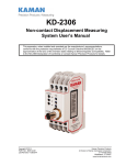
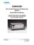
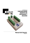
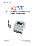
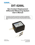
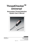
KDM-8206
Non-Contact Displacement Measuring
System User’s Manual
This apparatus, when installed and operated per the manufacturer’s recommendations,
conforms with the protection requirements of EC Council Directive 89/336/EEC on the
approximation of the laws of the member states relating to Electromagnetic Compatibility. Refer
to the KDM-8206 Declaration of Conformity or contact Kaman Precision Products for details.
Copyright © 2014
PART NO: 860516-001
Last Revised: 12/05/2014
Kaman Precision Products
A Division of Kaman Aerospace Corporation
217 Smith Street
Middletown, CT 06457
www.kamansensors.com
Table of Contents
PART 1 – KDM-8206 DESCRIPTION ................................................................................................... 3
PART 2 – CONNECTING THE KDM-8206............................................................................................ 5
PART 3 – KDM-8206 OUTPUTS ........................................................................................................... 7
3.1 ANALOG VOLTAGE OUTPUT: ........................................................................................................... 7
3.2 4-20 MA CURRENT OUTPUT: .......................................................................................................... 7
3.3 DEMODULATOR OUTPUT: ............................................................................................................... 7
3.4 DIFFERENTIAL (BALANCED) OUTPUT: .............................................................................................. 8
PART 4 – CALIBRATING THE KDM-8206 ........................................................................................... 9
4.1 CALIBRATION CONTROLS ............................................................................................................... 9
4.1.1 MIN CONTROLS ......................................................................................................................... 9
4.1.2 MID CONTROLS ....................................................................................................................... 10
4.1.3 MAX CONTROLS ...................................................................................................................... 10
4.2 CALIBRATION METHODS ............................................................................................................... 11
4.3 CALIBRATION PROCEDURES ......................................................................................................... 12
4.3.1 FULL SCALE CALIBRATION PROCEDURE (VOLTAGE).................................................................... 12
4.3.2 FULL SCALE CALIBRATION PROCEDURE (CURRENT) ................................................................... 13
4.3.3 BIPOLAR VOLTAGE OUTPUT CALIBRATION PROCEDURE .............................................................. 14
4.3.4 ALTERNATE BIPOLAR VOLTAGE OUTPUT CALIBRATION ............................................................... 15
4.3.5 HIGH ACCURACY BAND VOLTAGE CALIBRATION ......................................................................... 16
PART 5 – SYNCHRONIZING MULTIPLE MEASURING CHANNELS ............................................... 17
PART 6 – SYSTEM MODIFICATIONS ................................................................................................ 18
6.1 TEMPERATURE COMPENSATION ................................................................................................... 18
6.2 TARGET MATERIAL ...................................................................................................................... 18
6.3 SENSOR CABLE LENGTH .............................................................................................................. 18
6.4 BRIDGE CARD ............................................................................................................................. 19
6.5 INTERCHANGEABILITY OF KDM-8200 & KDM-8206 MEASURING MODULES ................................... 20
List of Figures
Figure 1
Figure 2
Figure 3
Figure 4
Figure 5
Figure 6
KDM-8206 Circuit .................................................................................................................. 3
Rear View of KDM-8206 Measuring Module ......................................................................... 5
J7 Location ............................................................................................................................ 8
Front View of KDM-8206 Measuring Module ......................................................................... 9
4-20mA Output Connections ............................................................................................... 13
Bridge Card Location ........................................................................................................... 19
www.kamansensors.com
PART NO: 860516-001
Last Revised: 12/05/14
2
PART 1 – KDM-8206 DESCRIPTION
Kaman Precision Products’ Model KDM-8206 is a non-contact, linear, analog displacement
measuring system. The system operates on a traditional inductive bridge circuit. This easy-to-use,
versatile system can be utilized for precision static and dynamic measurements of conductive targets.
The sensor coil makes up one or two legs (depending on single or dual coil sensor) of a balanced
bridge network. As the target changes position within the sensor field, the bridge network senses
impedance changes in the sensor coil. These changes are converted to an analog voltage or
current signal directly proportional to target displacement.
Figure 1 KDM-8206 Circuit
KDM-8206 product is a replacement for the KDM-8200 series product and has many improved
features, but uses the same type enclosure and Euro connector. The MIN, MID, and MAX
adjustments were labeled Zero, Gain, and Linearity adjustment controls respectively in the KDM8200 systems.
A KDM-8206 Measuring Module is the signal conditioning electronics unit. It is packaged in a
Eurocard 3U by 7T enclosure.
A KDM-8206 Measuring Channel consists of two subassemblies: a sensor with either an integral
or a removable cable, and a Measuring Module. The Measuring Channel is preconfigured at the
factory for a particular sensor, cable length, target material, and measuring range. The KDM8206 Measuring Channel is a RoHS compliant, CE Marked design. To maintain the CE Mark, the
following precautions are necessary:
www.kamansensors.com
PART NO: 860516-001
Last Revised: 12/05/14
3
1. I/O cable length is limited to a maximum of 30 m (100 ft).
2. The Eurocard electronics are supplied with a cover over to protect the circuit from damage
due to Electrostatic Discharge (ESD). Removal of the cover makes the unit susceptible to
ESD damage and it must be handled accordingly.
3. The electronics power and I/O must be isolated from the AC Mains and not subject to
transient over-voltages. That is, it must be powered by a D.C. secondary circuit that is
reliably grounded, capacitively- filtered, with peak-to-peak ripple less than 10% of the D.C.
component.
A KDM-8206 Measuring System consists of multiple Measuring Channels installed in a rack
enclosure. The rack typically includes a 110/220 VAC, 50/60 Hz power supply and may also
contain a digital display.
www.kamansensors.com
PART NO: 860516-001
Last Revised: 12/05/14
4
PART 2 – CONNECTING THE KDM-8206
All input, output, and synchronization connections to the KDM-8206 Measuring Module are at the
terminals of the Euro connector on the rear of the enclosure.
The Measuring Module is designed for insertion in a 3U/84HP rack enclosure. The rack provides
a mating Euro connector and input power supply. The sensor input is via a TBNC connector on
the rear panel of the rack. The output signal is a BNC coaxial connector also on the real panel.
Refer to the separate manual for rack details and operation. A Measuring Channel can be
operated independently of a rack or installed in a user provided rack if connected as detailed in
the table below.
Figure 2 Rear View of KDM-8206 Measuring Module
KDM-8206 Measuring Module Connections
Function
Pin C
Pin A
Function
+15 VDC in
NC
- 15 VDC in
NC
Ground
NC
V+ Out
V - Out
NC
NC
NC
NC
Ground
Synch Out
Sensor Return
2
4
6
8
10
12
14
16
18
20
22
24
26
28
30
2
4
6
8
10
12
14
16
18
20
22
24
26
28
30
+15 VDC in
NC
- 15 VDC in
NC
Ground
NC
V+ Out
V - Out
NC
I Out High
I Out Low
Demodulator Out
Ground
Synch In
Sensor Return
Sensor Inactive Coil
32
32
Sensor Active Coil
www.kamansensors.com
PART NO: 860516-001
Last Revised: 12/05/14
5
All connections in the table are present in a Kaman supplied rack enclosure; no additional wiring must
be specified. Some comments on the connections in this table are as follows:
1. NC = Not Connected
2. Single channel voltage output is between pins A/C 14 and Ground. This is connected to the
upper BNC connector on rear panel of the rack.
3. Differential voltage output is between pins A/C 14 (V+Out) and A/C 16 (V-Out). Output at pins
A/C 16 is not present unless enabled on the Measuring Channel PCB. Refer to section 3.4 of
this manual. V-Out is connected to the lower BNC connector on the rear panel of the rack.
The lower BNC connector is not installed unless differential output is requested.
4. Demodulator output on pin A 24 can be connected to the BNC connector on the rear panel of
the rack in place of V+Out on request. Modification to the channel backplane in the rack is
required.
A good quality linear or switching supply with an output of +15 and -15 VDC is recommended for best
(lowest noise) performance.
Sensor installation recommendations and guidelines are given in Kaman Measuring System’s
Inductive Technology Handbook. A copy of this handbook is available from the website.
www.kamansensors.com
PART NO: 860516-001
Last Revised: 12/05/14
6
PART 3 – KDM-8206 OUTPUTS
The KDM-8206 Measuring Channel has a variety of analog outputs. Standard outputs are:
•
Vout (single ended voltage)
•
Iout (4-20 mA current).
Optional outputs are:
•
Low voltage (0-1, 0-2)
•
Differential (balanced) voltage
•
Demodulator output
•
Reverse current (20-4 mA)
Modifications to the Measuring Module and/or Rack may be required for the optional outputs.
Single ended voltage calibration is provided unless otherwise specified.
Voltage outputs are accessed:
Between pins A/C 14 and A/C 16 on the Euro connector
On the rear panel BNC coaxial connector, if installed in a rack
Current output is accessed:
Between pins A20 and A22 on the Euro connector
On the rear panel two position terminal block, if installed in a rack
3.1 Analog Voltage Output:
Unless otherwise specified, the Measuring Channel will be factory calibrated for 0-10 VDC over
the full measuring range of the sensor. Other typical outputs are 0-5, ±5 VDC, and ±10 VDC.
The KDM-8206 output may also be adjusted to provide a specific sensitivity, such as 1 V/mm.
The Measuring Channel in a standard configuration can be adjusted for output ranges of 0-3 VDC
and greater. Lower ranges are available on request and require modification of the Measuring
Channel PCB.
3.2 4-20 mA Current Output:
For industrial applications or long output cable lengths, a 4–20 mA current output may be used. The
loop is powered by the KDM-8206. The current output is designed for a typical 250 ohm load.
However, the current output can provide a precise output into a load from 0 (zero) to 1,000 (1K)
ohms.
3.3 Demodulator Output:
Demodulator output is available between pin A24 and ground (pins A/C10 and A/C26) on the Euro
connector. It is also available at the test points on the front panel. This is the output from the
Synchronous Demodulator before any signal conditioning or linearization. It operates inversely to the
normal output voltage with highest output at the shortest distance.
www.kamansensors.com
PART NO: 860516-001
Last Revised: 12/05/14
7
Demodulator output is typically used for trouble-shooting purposes. It can also be used for special
applications when linearized output may be saturated under certain operating conditions.
A special calibration record of this output can be provided upon request. No attempt is made to
linearize or otherwise adjust demodulator output for the calibration record; it is a record of the output
only.
3.4 Differential (Balanced) Output:
For industrial applications, high noise environments or long output cable lengths, an optional
differential output is available. This provides two opposite polarity voltage signals that can be
combined (summed) at a differential input to cancel noise and provide a higher signal. Output as high
as ±20 VDC is available differentially.
NOTE: Since this is true differential, grounding either side can cause failure.
To change the voltage output from single ended to differential (the difference between V+ and VOutputs); change the J7 jumper on the KDM-8206 Measuring Channel from positions 1 and 2 to
positions 2 and 3.
When installed in a Sub-Rack or Instrument Enclosure, the rack back panel PCB with a V- BNC
connector is required. The back panel PCBs does not include this connector unless requested.
Figure 3 J7 Location
www.kamansensors.com
PART NO: 860516-001
Last Revised: 12/05/14
8
PART 4 – CALIBRATING THE KDM-8206
Figure 4 Front View of KDM-8206 Measuring Module
4.1 Calibration Controls
There are 6 controls to calibrate the KDM-8206, all located on the front panel and accessible by the
narrow end of an adjustment tool. The controls are: Coarse & Fine MIN, Coarse & Fine MID, Coarse
& Fine MAX. The terms MIN, MID, and MAX refer to which part of the measuring range that the
control is intended to adjust.
Coarse controls give a large change in output and are always adjusted first. Fine controls give a
smaller change in output and are used in final adjustments when the difference between actual and
desired voltage is 100 mV (0.1 mA for current calibration) or less. Actual sensitivity of the fine
controls will vary with sensor type.
The calibration controls have been relabeled from previous versions of Kaman products. Instead of
Offset, Gain and Linearity, the terms MIN, MID, and MAX are used to be more descriptive of where in
the normal displacement range they are adjusted.
4.1.1 MIN Controls
The Min Controls (Coarse & Fine) set the electrical zero point. This control is also referred to as the
“electrical offset”. As illustrated in the diagram below, the Min controls adjust the point at which
output intercepts the x-axis.
www.kamansensors.com
PART NO: 860516-001
Last Revised: 12/05/14
9
+OUTPUT
ZERO
INI TIAL CALIBRATI ON
ZERO
AFTER CONTROL
ADJUSTMENT
-OUTPUT
TARGET
DISPLACEMENT
After calibration, the MIN controls can be used to shift system output anywhere from 40-60% below
the x-axis, depending on sensor, sensor mounting and gain. This feature is useful in applications
where a ± deviation from a standard or a bipolar output is required.
The MIN controls can be utilized for final positioning of the output after installing the sensor in it a
mechanical fixture. In general, limit the amount of adjustment to tens of mili-volts of output
adjustment to avoid altering the factory calibration.
4.1.2 MID Controls
INCREASED GAIN
INITIAL CALIBRATION
DECREASED GAIN
-OUTPUT
+OUTPUT
The MID controls (Coarse & Fine) affect the change in output of a system in volts due to a given
change in displacement. The MID control sets the sensitivity or scale factor (Volts/mil or mm). The
diagram shows how the slope of the output curve changes as gain is increased and decreased.
4.1.3 MAX Controls
The Coarse and Fine MAX controls affect the shape of the system output curve. The closer the
output is to a straight line, the more accurate the measurement readings. When calibrating,
adjustment of the Max controls interacts with the MIN and MID controls. The MAX controls are
primarily used to swing the full-scale endpoint. Due to the effect of the log amp, it will have some
effect on the MID and less effect on the MIN.
www.kamansensors.com
PART NO: 860516-001
Last Revised: 12/05/14
10
4.2 Calibration Methods
The KDM-8206 has three possible calibration methods. The current output can only be calibrated for
4 to 20 mA, so there is no possible bipolar calibration.
Full Scale:
(Voltage Out) Output from 0 VDC to some maximum value.
(Current Out) Output from 4 mA to 20 mA
Bipolar:
Negative output for first half of range; positive output for second half.
High Accuracy Band: Increased linearity by using only part of the full-scale Measuring range
(Voltage or Current).
Depending on the application, select one of three procedures outlined above to calibrate a system.
Before calibration, we recommend that you become familiar with the following information to ensure
that you have made the necessary considerations regarding your particular application.
Full Scale Calibration
VDC
With a thorough knowledge of calibration variables and accurate application of the calibration
procedures described in the following pages, you can achieve optimum results. Deviations or
shortcuts can result in operator-induced errors and may complicate rather than solve measurement
problems.
offset
Bipolar Output Calibration
VDC
DISPLACEMENT
offset
High Accuracy Band
Calibration
VDC
DISPLACEMENT
offset
CALIBRATED
RANGE
DISPLACEMENT
www.kamansensors.com
PART NO: 860516-001
Last Revised: 12/05/14
11
4.3 Calibration Procedures
Here are some general comments that are applicable to all calibration procedures:
1. Mechanical positioning of the sensor must be performed accurately using a calibrated
micrometer fixture, precision spacers, or other dimensional standard.
2. A sample of the actual material to be measured by the system must be used as a calibration
target. Conductivity of the measured material affects system performance.
3. An inductive sensor always has an offset between the sensor face and start of its measuring
range. The offset serves two purposes a) it prevents mechanical damage caused by the
target striking the sensor face. b) It removes a very non-linear part of sensor output from the
measuring range making calibration easier, and performance much more linear. In general,
the offset is approximately 10 – 20% of the specified range.
4. Select the calibration procedure that is best for the application.
5. Select the proper offset distance, full-scale range, and desired voltage output. Calculate the
midscale range and output.
4.3.1 Full Scale Calibration Procedure (Voltage)
Full-scale calibration produces an output voltage that varies from 0 Vdc when the target is closest to
the sensor to some maximum positive voltage when the target is farthest from the sensor.
VDC
Monitor the voltage at the output BNC connector on the rack, or between pins C14 and Ground on the
Euro connector, or between connections OUT and GND on the front panel.
Full Scale Calibration
offset
0
DISPLACEMENT
1. Install the sensor in the calibration or application fixture at the offset distance from the target.
2. Position the target using the micrometer fixture or spacers so that the total distance between
the sensor and target is equal to the specified full-scale displacement for that sensor, plus
offset.
3. Adjust the MID controls so that system output equals the desired full-scale output voltage.
4. Reposition the target to minimum displacement (i.e. offset). Adjust the MIN controls until the
output voltage reads 0 VDC.
5. Reposition the target to mid-scale plus offset and adjust the MID controls until the output
voltage reads exactly half of the full-scale value.
www.kamansensors.com
PART NO: 860516-001
Last Revised: 12/05/14
12
6. Reposition the target to full-scale displacement, plus offset. Read the output voltage and
note the difference between the actual reading and the desired reading. Adjust the MAX
controls until the output reads the desired voltage level, then continue past the desired
reading by an amount equal to the first difference you noted. This technique is called 100%
oversetting and is used to reduce the number of iterations needed to calibrate the system.
For example, if the output reads 9.5 volts and the desired reading is 10.0, adjust the MAX
controls until the output reads 10.5.
7. Repeat Steps 4 through 6 as many times as necessary until the desired output voltage at
each point is obtained without additional adjustment.
4.3.2 Full Scale Calibration Procedure (Current)
Full Scale Calibration for the Current (4-20mA) output is similar to voltage calibration. The procedure
to calibrate for current output is performed in two steps.
STEP 1:
Perform a full scale calibration procedure for 0-10 VDC output per section 3.2.1. The 4-20 mA output
has been pre-set at the factory to correspond to a voltage output of 0-10 VDC. It is designed to give
full range only for a 0-10 VDC output.
Leave the sensor in the calibration fixture as it is required for step 2.
STEP 2:
This procedure requires a current meter or multimeter with a current range. Connect the current
meter in series with a 250 ohm load. Monitor the current at the output Terminal Block on the rear
panel of the rack or between pins A20 and A22 on the Euro connector.
Terminal Block IOr Euro connector pin A22
Load
250 ohm
(Typical)
Terminal Block I+
Or Euro connector pin A20
-
+
Current Meter
Figure 5 4-20mA Output Connections
Note the I+/I- output is a true current source. Shorting the two pins together will not cause damage.
Calibration uses a 250 ohm resistor to simulate a current receiver for the highest accuracy.
www.kamansensors.com
PART NO: 860516-001
Last Revised: 12/05/14
13
With the 250 ohm load and current meter connected as in FIGURE 4, verify the calibration. Some
adjustment of the front panel controls may be necessary to “fine tune” the current output.
1. Position the target to minimum displacement (i.e. offset). Adjust the MIN controls until the
output is 4 mA.
2. Reposition the target to mid-scale. Adjust the MID controls until the output voltage reads 12
mA.
3. Reposition the target to full-scale displacement. Adjust the MAX controls until the output
reads 20 mA.
4. Repeat steps 1 through 3 as many times as necessary until the desired output at each point
is obtained without further adjustment.
4.3.3 Bipolar Voltage Output Calibration Procedure
Bipolar Output Calibration
VDC
When you use this calibration procedure, output voltage will range from a negative voltage for the first
half of your measuring range to a positive output for the second half of the range.
offset
DISPLACEMENT
Use this method when your application requires a positive and negative output deviation from some
nominal value, in this case, 0 VDC
In a bipolar calibration, clockwise rotation of the MIN controls cause output to go more positive;
whereas, clockwise rotation of the MID controls increases gain more negatively in the lower half of
the range and more positively in the upper half. Because of this, you will adjust the MID controls
when the target is closest to the sensor and adjust the MIN controls at the mid-scale position.
1.
Install the sensor in the calibration or application fixture at the offset distance.
2.
Position the target using the micrometer fixture or spacers so that the total distance between
the sensor and target is equal to the specified full-scale displacement for that sensor, plus
offset.
3.
Adjust the MAX controls until the output is equal to the desired full-scale reading.
4.
Reposition the target so that it is at mid-scale and adjust the MIN controls until the output
reads zero.
www.kamansensors.com
PART NO: 860516-001
Last Revised: 12/05/14
14
5.
Reposition the target to minimum displacement (i.e. offset) and adjust the MID controls until
output reads the desired negative output voltage.
6.
Reposition the target to full-scale displacement, plus offset. Read the output voltage and
note the difference between the actual reading and the desired reading. Adjust the MAX
controls until the output reads the desired voltage level, then continue past the desired
reading by an amount equal to the first difference you noted. This technique is called 100%
oversetting and is used to reduce the number of iterations needed to calibrate the system.
7.
Repeat Steps 4 through 6 as many times as necessary until the desired output voltage at
each point obtained without additional adjustment.
4.3.4 Alternate Bipolar Voltage Output Calibration
You may not be able to achieve maximum sensitivity using this technique. This method may be
preferred if the maximum voltage does not exceed +10 VDC.
1. Use the Full-Scale procedure in section 4.3.1 to calibrate the system initially from 0 VDC to
the desired maximum.
2. Position the target at mid-scale and adjust the MIN control counterclockwise until output
reads 0 VDC.
3. Check the two ends, the points closest and farthest from the sensor, to verify they equal
minus and plus one half of the original full-scale output voltage. For example, if your original
full-scale voltage was 0-4 VDC, it should now be -2 to +2.
In theory, adjusting the MIN controls in this technique should not affect sensitivity or linearity. In
practice, however, you may see a very slight change indicated by voltage readings other than minus
and plus one-half full scale. The primary bipolar technique can now be used to fine-tune the
calibration.
www.kamansensors.com
PART NO: 860516-001
Last Revised: 12/05/14
15
VDC
4.3.5 High Accuracy Band Voltage Calibration
High Accuracy Band
Calibration
offset
CALIBRATED
RANGE
0
DISPLACEMENT
This procedure is used to monitor changes in position that are less than the specified linear
measuring range of the sensor, or for increased accuracy over a smaller range when not concerned
about high accuracy outside of that range.
The high accuracy band procedure maximizes the linearity of output within a calibrated span. The
sensor installed in your system has a specified linear measuring range that defines system
performance characteristics, such as linearity, resolution and long-term stability.
Maximum linearity is centered on the mid-point of the sensor’s specified maximum linearity measuring
range anywhere between 25-75% of full-scale. For example, if you have a system with a 40 mil
specified range; its most linear region will be between 10 and 30 mils.
While decreasing the linear measuring range of your system, it will improve system performance;
conversely, increasing measuring range will degrade performance. Depending upon measurement
objectives, either can be used.
As you perform a high accuracy band calibration, keep in mind that the smaller the calibrated span
the more interactive the controls will become. More interaction means more iteration before the
system is fully calibrated.
When the desired span is below 20% of specified linear measuring range, the additional improvement
in linearity is generally not worth the trouble caused by control interaction.
1. Install the sensor in the calibration or application fixture at the offset distance.
2. Define the reduced measurement span you will use.
3. Position the target so that it is at the maximum displacement of your defined span, plus
offset. Adjust the MAX controls until the output reads the desired maximum voltage.
4. Reposition the target at the minimum displacement of your defined span (plus offset) and
adjust the MIN controls to read the desired voltage at that point. The desired voltage
does not have to be zero.
5. Reposition the target at the mid-point between the end points of the desired span. Adjust
the MID controls until the output reads half the value between minimum and maximum
output.
6. Reposition the target so that it is at the maximum displacement of the span relative to the
sensor. Note the difference between the actual reading and the desired reading. Adjust
the MAX controls until the output reads the desired voltage level, then continue past the
desired reading by an amount equal to the first difference you noted.
7. Repeat Steps 3 through 6 as many times as necessary until you reach the desired output
voltage at each point without additional adjustment.
www.kamansensors.com
PART NO: 860516-001
Last Revised: 12/05/14
16
PART 5 – SYNCHRONIZING MULTIPLE MEASURING
CHANNELS
When sensors are used in close proximity to one another, performance will be compromised unless
the Measuring Channels are synchronized. Performance degradation is due to interaction of the
sensor fields and is likely to appear as a low frequency oscillation on the output signal. In general,
sensors located adjacent to each other with less than 3x sensor diameter spacing will require
synchronization.
When inserted into a Kaman supplied rack enclosure, the KDM-8206 Eurocard systems are
automatically synchronized together. The Eurocard on the left side of the rack (when viewed from the
front) is the master. All Measuring Channels to the right of the master become slaves. No
modification to the Measuring Module is required. Measuring Modules sense the presence of an
input oscillator signal on pin A28 of the Euro connector. A slave channel will then use the input
oscillator signal rather than the signal from its own oscillator to excite the sensor connected to that
channel.
If the signal from a master channel is lost, the next measuring channel in the sequence assumes the
function of a master.
When supplied as part of a rack assembly, measuring channels are calibrated in the rack. To
maximize performance accuracy, measuring channels should be used in the same rack slot where
they were calibrated.
www.kamansensors.com
PART NO: 860516-001
Last Revised: 12/05/14
17
PART 6 – SYSTEM MODIFICATIONS
6.1 Temperature Compensation
While inductive sensors offer advantages over competing technologies, one of the limitations of this
technology is thermal error due to varying temperature at the sensor location. The effect of
temperature changes can be minimized, but not totally eliminated. These thermal errors appear in
two forms:
1. Thermal Zero Shift – a change in where the output voltage intersects zero on the output
curve. In the KDM-8206 this effect cannot be compensated (reduced), only characterized.
2. Thermal Sensitivity Shift – a change in slope of the output voltage curve. This effect can
be reduced by the temperature compensation process.
Note that the temperature changes referenced apply to the sensor only. The Measuring Module must
be maintained in a temperature stable environment within the temperature band specified.
o
Thermal sensitivity shift for a standard KDM-8206 system is 0.1% of full-scale output per F (0.18%
o
per C). A system can be temperature compensated to reduce thermal sensitivity shift to 0.02% of full
o
o
scale per F (0.036% per C).
This procedure must be performed at the factory as it involves component changes to the circuit
o
o
board. The standard temperature compensation is performed over a 100 F (55 C) temperature
band.
6.2 Target Material
Each system is individually set up and calibrated at the factory for a specific material. Changing the
target material from the material used for calibration will affect system performance. This is due to
different electrical conductivities and ferro-magnetic properties of conductive materials. When target
material is changed, a calibration adjustment at a minimum is recommended. Reference the
guidelines in section 6.4 for additional system changes that may be required.
6.3 Sensor Cable Length
The sensor cable is part of the inductive bridge circuit. As such, any changes to the cable can affect
system calibration and performance. Some guidelines about modifications to the cable are:
1. Addition of feed through connectors generally does not affect system performance.
2. Small changes to cable length usually require only system recalibration.
3. Contact a Kaman applications engineer for guidance when making changes to the sensor
cable.
www.kamansensors.com
PART NO: 860516-001
Last Revised: 12/05/14
18
6.4 Bridge Card
The KDM-8206 Measuring Module is stocked in two basic versions, with a 500 KHz oscillator, and
with a 1 MHz oscillator. Unique circuitry to accommodate different sensors, cable lengths, and target
material (as necessary), is added to the Measuring Module in the form of a plug in circuit card. This
small circuit card is called a “bridge card”. Some generalizations concerning the bridge card are:
1. Different bridge cards are required for ferrous and non-ferrous target materials for small
sensors (.5U1, .5U2, 1U1, 1S/1SM, 1SU/1SUM, and 1UEP).
2. For sensors 2S and larger, a different bridge card is generally not required if target material is
changed. Changing target materials requires only system recalibration to the new material.
3. The bridge card must be matched to the operating frequency of the Measuring Channel,
sensor type, and sensor cable length.
The bridge card may be replaced as follows. Refer to FIGURE 5.
NOTE: Electrostatic Discharge (ESD) procedures must be followed.
1. Remove the six screws securing the Eurocard cover with a small screwdriver. Remove the
cover from the control module.
2. The bridge card is installed in a socket at the lower center of the circuit board. Remove the
bridge card from the socket.
3. Insert the replacement bridge card into the socket. Make certain to align the ground pin on
the bridge card to the socket closes to the Euro connector.
4. Replace the Eurocard cover and attach with screws removed in step 1.
5. The Measuring Channel (sensor and Measuring Module) must be recalibrated prior to use to
ensure accurate measurements.
Figure 6 Bridge Card Location
www.kamansensors.com
PART NO: 860516-001
Last Revised: 12/05/14
19
6.5
Interchangeability of KDM-8200 & KDM-8206 Measuring
Modules
KDM-8206 and KDM-8200 Measuring Modules are physically interchangeable in a 3U/84HP rack
enclosure. In general, a KDM-8206 Measuring Module can be used in a KDM-8200 rack and a KDM8200 Measuring Module can be used in a KDM-8206 rack enclosure. However, note the following
comments and precautions:
1. The Euro connector pin outs for main connections (input power, ground, voltage output,
sensor input) are identical on both systems.
2. Both systems require +15 and –15 VDC input. However, the KDM-8200 system requires a
linear power supply, as provided in a KDM-8200 rack enclosure. The KDM-8206
incorporates more input voltage filtering and can use a switching power supply, as provided
in a KDM-8206 rack enclosure. Installing a KDM-8200 measuring channel in a KDM-8206
rack will increase noise on the output signal.
3. KDM-8200 and KDM-8206 Measuring Channels cannot be mixed in the same rack. Their
oscillator and synchronization signals are incompatible.
4. A KDM-8206 Measuring Channel configured for differential output cannot be used in a KDM8200 rack. Damage to the measuring channel PCB will result.
5. Some KDM-8200 racks were configured for function modules. A KDM-8206 Measuring
Channel cannot be used in these racks.
6. Sensor connectors are different between the two systems. The KDM-8200 sensors have
single or dual SMA connectors depending on sensor construction. All KDM-8206 sensors
have TBNC connectors.
www.kamansensors.com
PART NO: 860516-001
Last Revised: 12/05/14
20