1
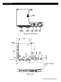
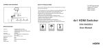
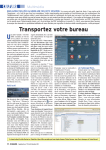
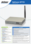
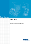
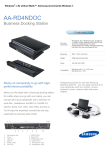
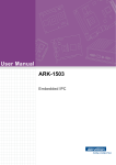
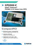
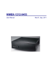
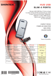
Introduction
MIO-6260 MIO/160 Module with 1xLAN, 4xUSB, 2xCOM
MIO-6260 MIO/160 Module with 1xLAN,
4xUSB, 2xCOM
Startup Manual
Features
The most flexible interface for Embedded
Applications
• 1 Fast Ethernet port (Optional)
Today is an embedded world, but many standard embedded single board computers cannot meet 100% of application specifications because they are not flexible enough to
expand and develop the system.
• 2 RS-232/422/485 interfaces
A system design short cut
• 4 USB 2.0 ports
• Cableless
Specifications
MIO/160 (Module I/O 160) is an open pin definition interface from Advantech. The MIO/160 interface integrates the
most popular bus signals together into a high-density 160pin connector. These popular interfaces include PCI, USB,
DVO, SMBus, LPC, and AC97. With MIO/160, board engineers can speed up system project design and expand the
system easily.
• Ethernet (Optional)
Chipset: Intel 82551ER
Speed: 10/100 Mbps
Interface: one RJ-45 connector
Standard: IEEE802.3u 100 Base-T Fast Ethernet
Compatible
• USB
Chipset: NEC uD720101 PCI USB 2.0 controller
2 ports by USB connector, 2 ports by box header
Packing list
Before you begin installing your card, please make sure
that the following materials have been shipped:
• 1 MIO-6260
• 1 Startup manual
• COM
Chipset: SMSC SCH3114 Serial Ports Controller
2 RS-232/422/485 in one D-Sub connector
Auto Flow control
Jumperless, select RS-232/422/485 by BIOS
Mechanical and Environmental
• 1 CD ROM for MIO-6260 Driver/Utility
• 1 screw kit
p/n: 9660250000
• Dimensions (L x W): 102mm x 146mm
copper stud x 6 pcs
p/n: 1930000058
• Operating Temperature: 0 ~ 60°C
screw x 6 pcs
p/n: 1935030500
• Operating Humidity: 10% ~ 90% relative humidity, noncondensing
If any of these items are missing or damaged, contact
your distributor or sales representative immediately.
• Power Supply Voltage: 5V
• Power Requirements: 5V @ 100 mA
Note 1: Acrobat Reader is required to view any PDF
file. Acrobat Reader can be downloaded at:
http://www.adobe.com/products/acrobat/
readstep2.html (Acrobat is a trademark of
Adobe.)
For more information on this and other Advantech
products, please visit our website at:
http://www.advantech.com
http://www.advantech.com/eplatform
For technical support and service, please visit our
support website at:
http://www.advantech.com/support
This manual is for the MIO-6260 series Rev. A1.
Part No. 2006626000
1st Edition
May. 2006
MIO-6260 Startup Manual
1
CN5
RJ45+1G Transformer
Part Number 1652000102
Jumpers & Connectors
Description
Connectors on the board link it to external devices, such
as hard disk drives, and keyboard or expansion bus connectors. In addition, the board has a number of jumpers
that allow you to configure your system to suit your application.
RJ-45 phone jack 14P 90D(F) W/Xfam
P26-107-1AX9
Pin
Pin name
Pin
Pin name
1
TX+
2
TX-
3
RX+
4
GND
5
GND
6
RX-
The table below lists the function of each of the jumpers
and connectors.
7
GND
8
GND
9
GND
10
GND
Connectors
Label
CN1
CN2
CN3
CN4
CN5
COM1
COM2
11
VCC_LAN
12
ACTLED
13
VCC_LAN
14
LILED
COM1
COM Port1
CN1
Function
MIO/160 Connector
USB1 Connector
USB2 Connector
USB3-4 Connector
RJ45+1G Transformer
COM Port1
COM Port2
Part Number 1654000056
Description
MIO/160 Connector
Part Number 1654000073
Description
CN2
B/B CONN. 80P SMD 0.8mm 180D QSE080-01-F-D-A
D-SUB CON. 9P 90D(M) DIP
Pin
Pin name
Pin
Pin name
1
DCD
2
RXD
3
TXD
4
DTR
5
GND
6
DSR
7
RTS
8
CTS
9
RI
COM2
COM Port2
USB1 Connector
Part Number 1654904100
Description
USB Connector. Single port with rear Cover
90D(M)
Part Number 1654000056
Pin
Pin name
Pin
Pin name
Pin
Pin name
Pin
Pin name
1
VCC
2
P-
1
DCD
2
RXD
3
P+
4-6
GND
3
TXD
4
DTR
5
GND
6
DSR
7
RTS
8
CTS
9
RI
CN3
USB2 Connector
Part Number 1654904100
Description
USB Con. SINGLE Port Typewith REAR
Cover 90D(M)
Pin
Pin name
Pin
Pin name
1
VCC
2
P-
3
P+
4-6
GND
CN4
USB3-4 Connector
Part Number 1653000066
Description
Pin Header, 5x2P 180D(M) 2.54 mm W/O
PIN10 USB
Pin
Pin name
Pin
Pin name
1
VCC
2
VCC
3
P0-
4
P1-
5
P0+
6
P1+
7
GND
8
GND
9
GND
10
NC
2
MIO-6260 Startup Manual
Description
D-SUB Connector 9P 90D(M) DIP
Board Layout
Component Placement
Dimensions
MIO-6260 Startup Manual
3
FCC
This device complies with the requirements in part 15 of the FCC rules: Operation is subject to the following two conditions:
1.This device may not cause harmful interference, and
2.This device must accept any interference received, including interference that may cause undesired
operation.
This equipment has been tested and found to comply with the limits for a Class A digital device, pursuant to Part 15 of the FCC Rules. These limits are designed to provide reasonable protection against
harmful interference when the equipment is operated in a commercial environment. This equipment
generates, uses, and can radiate radio frequency energy and, if not installed and used in accordance
with the instruction manual, may cause harmful interference to radio communications. Operation of
this device in a residential area is likely to cause harmful interference in which case the user will be
required to correct the interference at his/her own expense. The user is advised that any equipment
changes or modifications not expressly approved by the party responsible for compliance would void
the compliance to FCC regulations and therefore, the user's authority to operate the equipment.
Caution!
There is a danger of a new battery exploding if it is incorrectly installed. Do not attempt to recharge,
force open, or heat the battery. Replace the battery only with the same or equivalent type recommended by the manufacturer. Discard used batteries according to the manufacturer’s instructions.
Achtung!
4
MIO-6260 Startup Manual