1
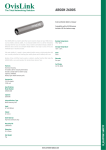
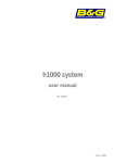
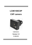
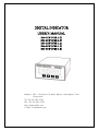
DIGITAL INDICATOR
USER’S MANUAL
DN-10W
DN-20W
DN-25W
DN-30W
DN-50W
(VER
(VER
(VER
(VER
(VER
5.0)
5.0)
1.0)
1.0)
1.5)
Address : 681-1 Cheoksan-Ri, Nami-Myeon, Cheongweon-Gun,
Chung-buk
TEL :82-43-260-2242
FAX : 82-43-260-2245
http://www.dacell.com
E-Mail : [email protected]
Contents
1. Features ⋅⋅⋅⋅⋅⋅⋅⋅⋅⋅⋅⋅⋅⋅⋅⋅⋅⋅⋅⋅⋅⋅⋅⋅⋅⋅⋅⋅⋅⋅⋅⋅⋅⋅⋅⋅⋅⋅⋅⋅⋅⋅⋅⋅⋅⋅⋅⋅⋅⋅⋅⋅⋅⋅⋅⋅⋅⋅⋅⋅⋅⋅⋅⋅⋅⋅⋅⋅⋅⋅⋅⋅⋅⋅⋅⋅⋅⋅⋅⋅⋅⋅⋅⋅⋅⋅⋅⋅⋅⋅⋅⋅⋅⋅⋅⋅⋅⋅⋅⋅⋅⋅⋅⋅⋅⋅⋅⋅⋅⋅⋅⋅⋅⋅⋅⋅⋅ 2
1-1. Calibration method ⋅⋅⋅⋅⋅⋅⋅⋅⋅⋅⋅⋅⋅⋅⋅⋅⋅⋅⋅⋅⋅⋅⋅⋅⋅⋅⋅⋅⋅⋅⋅⋅⋅⋅⋅⋅⋅⋅⋅⋅⋅⋅⋅⋅⋅⋅⋅⋅⋅⋅⋅⋅⋅⋅⋅⋅⋅⋅⋅⋅⋅⋅⋅⋅⋅⋅⋅⋅⋅⋅⋅⋅⋅⋅⋅⋅⋅⋅⋅⋅⋅⋅⋅⋅ 2
HOLD & PEAK HOLD ⋅⋅⋅⋅⋅⋅⋅⋅⋅⋅⋅⋅⋅⋅⋅⋅⋅⋅⋅⋅⋅⋅⋅⋅⋅⋅⋅⋅⋅⋅⋅⋅⋅⋅⋅⋅⋅⋅⋅⋅⋅⋅⋅⋅⋅⋅⋅⋅⋅⋅⋅⋅⋅⋅⋅⋅⋅⋅⋅⋅⋅⋅⋅⋅⋅⋅⋅⋅⋅⋅⋅⋅⋅⋅⋅⋅⋅⋅⋅⋅⋅⋅⋅⋅⋅⋅
Comparison Output ⋅⋅⋅⋅⋅⋅⋅⋅⋅⋅⋅⋅⋅⋅⋅⋅⋅⋅⋅⋅⋅⋅⋅⋅⋅⋅⋅⋅⋅⋅⋅⋅⋅⋅⋅⋅⋅⋅⋅⋅⋅⋅⋅⋅⋅⋅⋅⋅⋅⋅⋅⋅⋅⋅⋅⋅⋅⋅⋅⋅⋅⋅⋅⋅⋅⋅⋅⋅⋅⋅⋅⋅⋅⋅⋅⋅⋅⋅⋅⋅⋅⋅⋅⋅⋅⋅⋅
Data Back-up ⋅⋅⋅⋅⋅⋅⋅⋅⋅⋅⋅⋅⋅⋅⋅⋅⋅⋅⋅⋅⋅⋅⋅⋅⋅⋅⋅⋅⋅⋅⋅⋅⋅⋅⋅⋅⋅⋅⋅⋅⋅⋅⋅⋅⋅⋅⋅⋅⋅⋅⋅⋅⋅⋅⋅⋅⋅⋅⋅⋅⋅⋅⋅⋅⋅⋅⋅⋅⋅⋅⋅⋅⋅⋅⋅⋅⋅⋅⋅⋅⋅⋅⋅⋅⋅⋅⋅⋅⋅⋅⋅
Watch dog ⋅⋅⋅⋅⋅⋅⋅⋅⋅⋅⋅⋅⋅⋅⋅⋅⋅⋅⋅⋅⋅⋅⋅⋅⋅⋅⋅⋅⋅⋅⋅⋅⋅⋅⋅⋅⋅⋅⋅⋅⋅⋅⋅⋅⋅⋅⋅⋅⋅⋅⋅⋅⋅⋅⋅⋅⋅⋅⋅⋅⋅⋅⋅⋅⋅⋅⋅⋅⋅⋅⋅⋅⋅⋅⋅⋅⋅⋅⋅⋅⋅⋅⋅⋅⋅⋅⋅⋅⋅⋅⋅⋅⋅⋅⋅⋅⋅⋅⋅⋅⋅⋅⋅⋅⋅⋅⋅⋅⋅⋅⋅⋅⋅⋅⋅⋅⋅
2
2
2
2
2. Attention ⋅⋅⋅⋅⋅⋅⋅⋅⋅⋅⋅⋅⋅⋅⋅⋅⋅⋅⋅⋅⋅⋅⋅⋅⋅⋅⋅⋅⋅⋅⋅⋅⋅⋅⋅⋅⋅⋅⋅⋅⋅⋅⋅⋅⋅⋅⋅⋅⋅⋅⋅⋅⋅⋅⋅⋅⋅⋅⋅⋅⋅⋅⋅⋅⋅⋅⋅⋅⋅⋅⋅⋅⋅⋅⋅⋅⋅⋅⋅⋅⋅⋅⋅⋅⋅⋅⋅⋅⋅⋅⋅⋅⋅⋅⋅⋅⋅⋅⋅⋅⋅⋅⋅⋅⋅⋅⋅⋅⋅⋅
2-1. Attention for installation ⋅⋅⋅⋅⋅⋅⋅⋅⋅⋅⋅⋅⋅⋅⋅⋅⋅⋅⋅⋅⋅⋅⋅⋅⋅⋅⋅⋅⋅⋅⋅⋅⋅⋅⋅⋅⋅⋅⋅⋅⋅⋅⋅⋅⋅⋅⋅⋅⋅⋅⋅⋅⋅⋅⋅⋅⋅⋅⋅⋅⋅⋅⋅⋅⋅⋅⋅⋅⋅⋅⋅⋅⋅⋅⋅⋅⋅⋅⋅⋅⋅⋅⋅⋅⋅⋅⋅⋅⋅⋅⋅⋅
2-2. Attention for use ⋅⋅⋅⋅⋅⋅⋅⋅⋅⋅⋅⋅⋅⋅⋅⋅⋅⋅⋅⋅⋅⋅⋅⋅⋅⋅⋅⋅⋅⋅⋅⋅⋅⋅⋅⋅⋅⋅⋅⋅⋅⋅⋅⋅⋅⋅⋅⋅⋅⋅⋅⋅⋅⋅⋅⋅⋅⋅⋅⋅⋅⋅⋅⋅⋅⋅⋅⋅⋅⋅⋅⋅⋅⋅⋅⋅⋅⋅⋅⋅⋅⋅⋅⋅⋅⋅⋅⋅⋅⋅⋅
3. Specif ication ⋅⋅⋅⋅⋅⋅⋅⋅⋅⋅⋅⋅⋅⋅⋅⋅⋅⋅⋅⋅⋅⋅⋅⋅⋅⋅⋅⋅⋅⋅⋅⋅⋅⋅⋅⋅⋅⋅⋅⋅⋅⋅⋅⋅⋅⋅⋅⋅⋅⋅⋅⋅⋅⋅⋅⋅⋅⋅⋅⋅⋅⋅⋅⋅⋅⋅⋅⋅⋅⋅⋅⋅⋅⋅⋅⋅⋅⋅⋅⋅⋅⋅⋅⋅⋅⋅⋅⋅⋅⋅⋅⋅⋅⋅⋅⋅⋅⋅⋅⋅
3
3
3
4
4. Front Panel ⋅⋅⋅⋅⋅⋅⋅⋅⋅⋅⋅⋅⋅⋅⋅⋅⋅⋅⋅⋅⋅⋅⋅⋅⋅⋅⋅⋅⋅⋅⋅⋅⋅⋅⋅⋅⋅⋅⋅⋅⋅⋅⋅⋅⋅⋅⋅⋅⋅⋅⋅⋅⋅⋅⋅⋅⋅⋅⋅⋅⋅⋅⋅⋅⋅⋅⋅⋅⋅⋅⋅⋅⋅⋅⋅⋅⋅⋅⋅⋅⋅⋅⋅⋅⋅⋅⋅⋅⋅⋅⋅⋅⋅⋅⋅⋅⋅⋅⋅⋅⋅⋅⋅⋅⋅⋅⋅⋅⋅
5. Rear Panel ⋅⋅⋅⋅⋅⋅⋅⋅⋅⋅⋅⋅⋅⋅⋅⋅⋅⋅⋅⋅⋅⋅⋅⋅⋅⋅⋅⋅⋅⋅⋅⋅⋅⋅⋅⋅⋅⋅⋅⋅⋅⋅⋅⋅⋅⋅⋅⋅⋅⋅⋅⋅⋅⋅⋅⋅⋅⋅⋅⋅⋅⋅⋅⋅⋅⋅⋅⋅⋅⋅⋅⋅⋅⋅⋅⋅⋅⋅⋅⋅⋅⋅⋅⋅⋅⋅⋅⋅⋅⋅⋅⋅⋅⋅⋅⋅⋅⋅⋅⋅⋅⋅⋅⋅⋅⋅⋅⋅⋅⋅⋅⋅
6 . W i r i n g D i a g r a m ⋅ ⋅ ⋅ ⋅ ⋅⋅ ⋅ ⋅ ⋅ ⋅⋅ ⋅ ⋅ ⋅⋅ ⋅ ⋅ ⋅ ⋅ ⋅ ⋅⋅ ⋅ ⋅ ⋅⋅ ⋅ ⋅ ⋅⋅ ⋅ ⋅ ⋅ ⋅ ⋅⋅ ⋅ ⋅ ⋅ ⋅⋅ ⋅ ⋅ ⋅⋅ ⋅ ⋅ ⋅ ⋅ ⋅⋅ ⋅ ⋅ ⋅ ⋅⋅ ⋅ ⋅ ⋅⋅ ⋅ ⋅ ⋅ ⋅ ⋅⋅ ⋅ ⋅ ⋅ ⋅⋅ ⋅ ⋅ ⋅⋅ ⋅ ⋅ ⋅ ⋅ ⋅⋅ ⋅ ⋅ ⋅ ⋅⋅ ⋅ ⋅ ⋅⋅ ⋅ ⋅ ⋅
1) DN-10W, DN-50W ⋅⋅⋅⋅⋅⋅⋅⋅⋅⋅⋅⋅⋅⋅⋅⋅⋅⋅⋅⋅⋅⋅⋅⋅⋅⋅⋅⋅⋅⋅⋅⋅⋅⋅⋅⋅⋅⋅⋅⋅⋅⋅⋅⋅⋅⋅⋅⋅⋅⋅⋅⋅⋅⋅⋅⋅⋅⋅⋅⋅⋅⋅⋅⋅⋅⋅⋅⋅⋅⋅⋅⋅⋅⋅⋅⋅⋅⋅⋅⋅⋅⋅⋅⋅⋅⋅⋅⋅⋅⋅⋅⋅
5
6
8
8
DN-20W ⋅⋅⋅⋅⋅⋅⋅⋅⋅⋅⋅⋅⋅⋅⋅⋅⋅⋅⋅⋅⋅⋅⋅⋅⋅⋅⋅⋅⋅⋅⋅⋅⋅⋅⋅⋅⋅⋅⋅⋅⋅⋅⋅⋅⋅⋅⋅⋅⋅⋅⋅⋅⋅⋅⋅⋅⋅⋅⋅⋅⋅⋅⋅⋅⋅⋅⋅⋅⋅⋅⋅⋅⋅⋅⋅⋅⋅⋅⋅⋅⋅⋅⋅⋅⋅⋅⋅⋅⋅⋅⋅⋅
DN-25W ⋅⋅⋅⋅⋅⋅⋅⋅⋅⋅⋅⋅⋅⋅⋅⋅⋅⋅⋅⋅⋅⋅⋅⋅⋅⋅⋅⋅⋅⋅⋅⋅⋅⋅⋅⋅⋅⋅⋅⋅⋅⋅⋅⋅⋅⋅⋅⋅⋅⋅⋅⋅⋅⋅⋅⋅⋅⋅⋅⋅⋅⋅⋅⋅⋅⋅⋅⋅⋅⋅⋅⋅⋅⋅⋅⋅⋅⋅⋅⋅⋅⋅⋅⋅⋅⋅⋅⋅⋅⋅⋅⋅
DN-30W ⋅⋅⋅⋅⋅⋅⋅⋅⋅⋅⋅⋅⋅⋅⋅⋅⋅⋅⋅⋅⋅⋅⋅⋅⋅⋅⋅⋅⋅⋅⋅⋅⋅⋅⋅⋅⋅⋅⋅⋅⋅⋅⋅⋅⋅⋅⋅⋅⋅⋅⋅⋅⋅⋅⋅⋅⋅⋅⋅⋅⋅⋅⋅⋅⋅⋅⋅⋅⋅⋅⋅⋅⋅⋅⋅⋅⋅⋅⋅⋅⋅⋅⋅⋅⋅⋅⋅⋅⋅⋅⋅⋅
External Input ⋅⋅⋅⋅⋅⋅⋅⋅⋅⋅⋅⋅⋅⋅⋅⋅⋅⋅⋅⋅⋅⋅⋅⋅⋅⋅⋅⋅⋅⋅⋅⋅⋅⋅⋅⋅⋅⋅⋅⋅⋅⋅⋅⋅⋅⋅⋅⋅⋅⋅⋅⋅⋅⋅⋅⋅⋅⋅⋅⋅⋅⋅⋅⋅⋅⋅⋅⋅⋅⋅⋅⋅⋅⋅⋅⋅⋅⋅⋅⋅⋅⋅⋅⋅⋅⋅⋅⋅⋅⋅⋅⋅
8
9
9
9
1-2.
1-3.
1-4.
1-5.
2)
3)
4)
5)
7. How to use Hold mode ⋅⋅⋅⋅⋅⋅⋅⋅⋅⋅⋅⋅⋅⋅⋅⋅⋅⋅⋅⋅⋅⋅⋅⋅⋅⋅⋅⋅⋅⋅⋅⋅⋅⋅⋅⋅⋅⋅⋅⋅⋅⋅⋅⋅⋅⋅⋅⋅⋅⋅⋅⋅⋅⋅⋅⋅⋅⋅⋅⋅⋅⋅⋅⋅⋅⋅⋅⋅⋅⋅⋅⋅⋅⋅⋅⋅⋅⋅⋅⋅⋅⋅⋅⋅⋅⋅
7-1. How to use comparison output function ⋅⋅⋅⋅⋅⋅⋅⋅⋅⋅⋅⋅⋅⋅⋅⋅⋅⋅⋅⋅⋅⋅⋅⋅⋅⋅⋅⋅⋅⋅⋅⋅⋅⋅⋅⋅⋅⋅⋅⋅⋅⋅⋅⋅⋅⋅⋅⋅⋅⋅⋅⋅⋅⋅⋅⋅⋅⋅⋅⋅⋅⋅⋅⋅⋅⋅⋅⋅
8. S e t ti n g m od e ⋅ ⋅⋅⋅⋅ ⋅⋅⋅ ⋅⋅⋅ ⋅⋅⋅⋅ ⋅ ⋅⋅⋅⋅ ⋅⋅⋅ ⋅⋅⋅ ⋅⋅⋅⋅ ⋅ ⋅⋅⋅⋅ ⋅⋅⋅ ⋅⋅⋅ ⋅⋅⋅⋅ ⋅ ⋅⋅⋅⋅ ⋅⋅⋅ ⋅⋅⋅⋅ ⋅⋅⋅ ⋅ ⋅⋅ ⋅⋅ ⋅⋅⋅ ⋅⋅⋅⋅ ⋅⋅⋅ ⋅ ⋅⋅⋅⋅ ⋅⋅⋅ ⋅⋅⋅⋅ ⋅⋅⋅ ⋅ ⋅⋅⋅⋅
1) DN-10W, DN-50W ⋅⋅⋅⋅⋅⋅⋅⋅⋅⋅⋅⋅⋅⋅⋅⋅⋅⋅⋅⋅⋅⋅⋅⋅⋅⋅⋅⋅⋅⋅⋅⋅⋅⋅⋅⋅⋅⋅⋅⋅⋅⋅⋅⋅⋅⋅⋅⋅⋅⋅⋅⋅⋅⋅⋅⋅⋅⋅⋅⋅⋅⋅⋅⋅⋅⋅⋅⋅⋅⋅⋅⋅⋅⋅⋅⋅⋅⋅⋅⋅⋅⋅⋅⋅⋅⋅⋅⋅⋅⋅⋅⋅
10
12
14
14
2) DN-20W ⋅⋅⋅⋅⋅⋅⋅⋅⋅⋅⋅⋅⋅⋅⋅⋅⋅⋅⋅⋅⋅⋅⋅⋅⋅⋅⋅⋅⋅⋅⋅⋅⋅⋅⋅⋅⋅⋅⋅⋅⋅⋅⋅⋅⋅⋅⋅⋅⋅⋅⋅⋅⋅⋅⋅⋅⋅⋅⋅⋅⋅⋅⋅⋅⋅⋅⋅⋅⋅⋅⋅⋅⋅⋅⋅⋅⋅⋅⋅⋅⋅⋅⋅⋅⋅⋅⋅⋅⋅⋅⋅⋅
3) DN-25W ⋅⋅⋅⋅⋅⋅⋅⋅⋅⋅⋅⋅⋅⋅⋅⋅⋅⋅⋅⋅⋅⋅⋅⋅⋅⋅⋅⋅⋅⋅⋅⋅⋅⋅⋅⋅⋅⋅⋅⋅⋅⋅⋅⋅⋅⋅⋅⋅⋅⋅⋅⋅⋅⋅⋅⋅⋅⋅⋅⋅⋅⋅⋅⋅⋅⋅⋅⋅⋅⋅⋅⋅⋅⋅⋅⋅⋅⋅⋅⋅⋅⋅⋅⋅⋅⋅⋅⋅⋅⋅⋅⋅
8-1. Function mode (Function Set-up) ⋅⋅⋅⋅⋅⋅⋅⋅⋅⋅⋅⋅⋅⋅⋅⋅⋅⋅⋅⋅⋅⋅⋅⋅⋅⋅⋅⋅⋅⋅⋅⋅⋅⋅⋅⋅⋅⋅⋅⋅⋅⋅⋅⋅⋅⋅⋅⋅⋅⋅⋅⋅⋅⋅⋅⋅⋅⋅⋅⋅⋅⋅⋅⋅⋅⋅⋅⋅
1) How to set up Function ⋅⋅⋅⋅⋅⋅⋅⋅⋅⋅⋅⋅⋅⋅⋅⋅⋅⋅⋅⋅⋅⋅⋅⋅⋅⋅⋅⋅⋅⋅⋅⋅⋅⋅⋅⋅⋅⋅⋅⋅⋅⋅⋅⋅⋅⋅⋅⋅⋅⋅⋅⋅⋅⋅⋅⋅⋅⋅⋅⋅⋅⋅⋅⋅⋅⋅⋅⋅⋅⋅⋅⋅⋅⋅⋅⋅⋅⋅⋅⋅⋅⋅⋅⋅⋅⋅⋅⋅⋅⋅⋅⋅
15
16
17
17
2)
3)
8-2.
1)
How to set up Relay out data ⋅⋅⋅⋅⋅⋅⋅⋅⋅⋅⋅⋅⋅⋅⋅⋅⋅⋅⋅⋅⋅⋅⋅⋅⋅⋅⋅⋅⋅⋅⋅⋅⋅⋅⋅⋅⋅⋅⋅⋅⋅⋅⋅⋅⋅⋅⋅⋅⋅⋅⋅⋅⋅⋅⋅⋅⋅⋅⋅⋅⋅⋅⋅⋅⋅⋅⋅⋅⋅⋅⋅⋅⋅⋅⋅⋅⋅⋅⋅⋅⋅⋅⋅⋅⋅⋅⋅⋅⋅
Function mode table ⋅⋅⋅⋅⋅⋅⋅⋅⋅⋅⋅⋅⋅⋅⋅⋅⋅⋅⋅⋅⋅⋅⋅⋅⋅⋅⋅⋅⋅⋅⋅⋅⋅⋅⋅⋅⋅⋅⋅⋅⋅⋅⋅⋅⋅⋅⋅⋅⋅⋅⋅⋅⋅⋅⋅⋅⋅⋅⋅⋅⋅⋅⋅⋅⋅⋅⋅⋅⋅⋅⋅⋅⋅⋅⋅⋅⋅⋅⋅⋅⋅⋅⋅⋅⋅⋅⋅⋅⋅
Digital calibration (Calibration by sensor output value) ⋅⋅⋅⋅⋅⋅⋅⋅⋅⋅⋅⋅⋅⋅⋅⋅⋅⋅⋅⋅⋅⋅⋅⋅⋅⋅⋅⋅⋅⋅⋅⋅⋅⋅⋅⋅⋅⋅⋅⋅⋅⋅⋅⋅⋅⋅⋅⋅⋅⋅⋅
DN-10W, DN-50W ⋅⋅⋅⋅⋅⋅⋅⋅⋅⋅⋅⋅⋅⋅⋅⋅⋅⋅⋅⋅⋅⋅⋅⋅⋅⋅⋅⋅⋅⋅⋅⋅⋅⋅⋅⋅⋅⋅⋅⋅⋅⋅⋅⋅⋅⋅⋅⋅⋅⋅⋅⋅⋅⋅⋅⋅⋅⋅⋅⋅⋅⋅⋅⋅⋅⋅⋅⋅⋅⋅⋅⋅⋅⋅⋅⋅⋅⋅⋅⋅⋅⋅⋅⋅⋅⋅⋅⋅⋅⋅⋅⋅
18
19
26
26
2)
8-3.
1)
2)
DN-20W ⋅⋅⋅⋅⋅⋅⋅⋅⋅⋅⋅⋅⋅⋅⋅⋅⋅⋅⋅⋅⋅⋅⋅⋅⋅⋅⋅⋅⋅⋅⋅⋅⋅⋅⋅⋅⋅⋅⋅⋅⋅⋅⋅⋅⋅⋅⋅⋅⋅⋅⋅⋅⋅⋅⋅⋅⋅⋅⋅⋅⋅⋅⋅⋅⋅⋅⋅⋅⋅⋅⋅⋅⋅⋅⋅⋅⋅⋅⋅⋅⋅⋅⋅⋅⋅⋅⋅⋅⋅⋅⋅⋅
Actual load calibration (Calibration by standard weight) ⋅⋅⋅⋅⋅⋅⋅⋅⋅⋅⋅⋅⋅⋅⋅⋅⋅⋅⋅⋅⋅⋅⋅⋅⋅⋅⋅⋅⋅⋅⋅⋅⋅⋅⋅⋅⋅⋅⋅⋅⋅⋅⋅⋅⋅⋅⋅⋅⋅⋅⋅
DN-10W, DN-50W ⋅⋅⋅⋅⋅⋅⋅⋅⋅⋅⋅⋅⋅⋅⋅⋅⋅⋅⋅⋅⋅⋅⋅⋅⋅⋅⋅⋅⋅⋅⋅⋅⋅⋅⋅⋅⋅⋅⋅⋅⋅⋅⋅⋅⋅⋅⋅⋅⋅⋅⋅⋅⋅⋅⋅⋅⋅⋅⋅⋅⋅⋅⋅⋅⋅⋅⋅⋅⋅⋅⋅⋅⋅⋅⋅⋅⋅⋅⋅⋅⋅⋅⋅⋅⋅⋅⋅⋅⋅⋅⋅⋅
DN-20W ⋅⋅⋅⋅⋅⋅⋅⋅⋅⋅⋅⋅⋅⋅⋅⋅⋅⋅⋅⋅⋅⋅⋅⋅⋅⋅⋅⋅⋅⋅⋅⋅⋅⋅⋅⋅⋅⋅⋅⋅⋅⋅⋅⋅⋅⋅⋅⋅⋅⋅⋅⋅⋅⋅⋅⋅⋅⋅⋅⋅⋅⋅⋅⋅⋅⋅⋅⋅⋅⋅⋅⋅⋅⋅⋅⋅⋅⋅⋅⋅⋅⋅⋅⋅⋅⋅⋅⋅⋅⋅⋅⋅
27
28
28
29
3) DN-25W ⋅⋅⋅⋅⋅⋅⋅⋅⋅⋅⋅⋅⋅⋅⋅⋅⋅⋅⋅⋅⋅⋅⋅⋅⋅⋅⋅⋅⋅⋅⋅⋅⋅⋅⋅⋅⋅⋅⋅⋅⋅⋅⋅⋅⋅⋅⋅⋅⋅⋅⋅⋅⋅⋅⋅⋅⋅⋅⋅⋅⋅⋅⋅⋅⋅⋅⋅⋅⋅⋅⋅⋅⋅⋅⋅⋅⋅⋅⋅⋅⋅⋅⋅⋅⋅⋅⋅⋅⋅⋅⋅⋅
8-4. SPAN constant calibration
⋅⋅⋅⋅⋅⋅⋅⋅⋅⋅⋅⋅⋅⋅⋅⋅⋅⋅⋅⋅⋅⋅⋅⋅⋅⋅⋅⋅⋅⋅⋅⋅⋅⋅⋅⋅⋅⋅⋅
1) DN-10W, DN-50W ⋅⋅⋅⋅⋅⋅⋅⋅⋅⋅⋅⋅⋅⋅⋅⋅⋅⋅⋅⋅⋅⋅⋅⋅⋅⋅⋅⋅⋅⋅⋅⋅⋅⋅⋅⋅⋅⋅⋅⋅⋅⋅⋅⋅⋅⋅⋅⋅⋅⋅⋅⋅⋅⋅⋅⋅⋅⋅⋅⋅⋅⋅⋅⋅⋅⋅⋅⋅⋅⋅⋅⋅⋅⋅⋅⋅⋅⋅⋅⋅⋅⋅⋅⋅⋅⋅⋅⋅⋅⋅⋅⋅
8-5. Lock Set up⋅⋅⋅⋅⋅⋅⋅⋅⋅⋅⋅⋅⋅⋅⋅⋅⋅⋅⋅⋅⋅⋅⋅⋅⋅⋅⋅⋅⋅⋅⋅⋅⋅⋅⋅⋅⋅⋅⋅⋅⋅⋅⋅⋅⋅⋅⋅⋅⋅⋅⋅⋅⋅⋅⋅⋅⋅⋅⋅⋅⋅⋅⋅⋅⋅⋅⋅⋅⋅⋅⋅⋅⋅⋅⋅⋅⋅⋅⋅⋅⋅⋅⋅⋅⋅⋅⋅⋅⋅⋅
30
31
31
32
9. Product Inspection ⋅⋅⋅⋅⋅⋅⋅⋅⋅⋅⋅⋅⋅⋅⋅⋅⋅⋅⋅⋅⋅⋅⋅⋅⋅⋅⋅⋅⋅⋅⋅⋅⋅⋅⋅⋅⋅⋅⋅⋅⋅⋅⋅⋅⋅⋅⋅⋅⋅⋅⋅⋅⋅⋅⋅⋅⋅⋅⋅⋅⋅⋅⋅⋅⋅⋅⋅⋅⋅⋅⋅⋅⋅⋅⋅⋅⋅⋅⋅⋅⋅⋅⋅⋅⋅⋅⋅⋅⋅⋅⋅⋅⋅⋅⋅⋅⋅⋅⋅⋅⋅⋅⋅ 33
10. OPTION (OP-02, OP-03)
Option 02 (RS232C) ⋅⋅⋅⋅⋅⋅⋅⋅⋅⋅⋅⋅⋅⋅⋅⋅⋅⋅⋅⋅⋅⋅⋅⋅⋅⋅⋅⋅⋅⋅⋅⋅⋅⋅⋅⋅⋅⋅⋅⋅⋅⋅⋅⋅⋅⋅⋅⋅⋅⋅⋅⋅⋅⋅⋅⋅⋅⋅⋅⋅⋅⋅⋅⋅⋅⋅⋅⋅⋅⋅⋅⋅⋅⋅⋅⋅⋅⋅⋅⋅⋅⋅⋅⋅⋅⋅⋅⋅⋅⋅⋅⋅⋅⋅⋅⋅⋅⋅⋅⋅⋅⋅⋅ 34
Option 03 (RS485) ⋅⋅⋅⋅⋅⋅⋅⋅⋅⋅⋅⋅⋅⋅⋅⋅⋅⋅⋅⋅⋅⋅⋅⋅⋅⋅⋅⋅⋅⋅⋅⋅⋅⋅⋅⋅⋅⋅⋅⋅⋅⋅⋅⋅⋅⋅⋅⋅⋅⋅⋅⋅⋅⋅⋅⋅⋅⋅⋅⋅⋅⋅⋅⋅⋅⋅⋅⋅⋅⋅⋅⋅⋅⋅⋅⋅⋅⋅⋅⋅⋅⋅⋅⋅⋅⋅⋅⋅⋅⋅⋅⋅⋅⋅⋅⋅⋅⋅⋅⋅⋅⋅⋅ 36
1
1. Features
We thank you for using our product. Please refer to this manual or contact our office if
you find any problems during using our product.
This product is an indicator that emplifies the micro voltage signals from each sensor
and display in digital. It is mainly used to measure physical quantities of the items using
strain guage such as loadcell, pressure sensor, displacement sensor and torque sensor.
This product has the following special features.
1-1. Calibration Method
2 types of calibration systems are adopted. Calibration by actual load (standard
weight) and calibration by rated output of sensor .
1-2. Hold & Peak Hold
You can choose peak hold or sample hold .
1-3. Comparison Output
You can do set-up the maxium and lower limit value by the keys on the front panel
and output contact point signal of the rear panel.
1-4. Data Back-up
All the set-up values will be memorized on the flash memory so the inputted data can
be saved and no need to do the re-setting even in case of the interruption of the
electric power or power disconnection.
1-5. Watch dog
This function is for automatic reset in case the system is stopped due to the external
factors such as noise.
2
2. Attention
For the efficient and safe use, please carefully read and be fully aware of the
following details before using this product.
It is strictly forbidden to use this product for any other purpose of use or to attempt to
make any alteration on this product.
2-1. Attention for installation
• Please keep it out of wet places.
• Do not set it up near vibration & impulse, high temperature and humidity.
Keep it out of the direct rays of the sun. Set it up where there is less dust, and Keep
it out of direct air including salt and ion.
• Do not use when there is inflammable gas or heavy machinery, and smog.
• Ground earth-terminal ( ).
• Make wire separately from power system wiring and noise wiring.
• Make sure the use of 4 line sealed cable as a sensor cable. Too long cable leads to
measurement error due to wiring resistance (around 10meters).
2-2. Attention for use
During calibration, Do not input free-load state and real-weight load until it becomes
stable. Pressing Enter Key in unstable condition leads to calibration error.
Do not press any Key in use at one's discretion. Please refer to 7. Setting-up mode for
the function and method of Key.
3
3. Specification
Specification model
SIGNAL
ANALOG OUT
DN-50W
DN-10W
1 ~ 3mv/V
5V
Strain Gauge sensor
0~10V,
4~20mA
0~2Vrms
pulse
2Vrms/5kHz
Pressure sensor,
Differential
resistance
trans
displacement
displacement
(Bridge 120Ω, 350Ω,
MAX. Display
D/A Converter
DN-30W
10V, 24V
700Ω)
A/D Converter
DN-25W
0 ~ 10V, 4 ~ 20mA (according to customer request)
EXCITATION
Available sensor
DN-20W
1000times/sec
Temperature
ZERO
0.5㎶/℃
Characteristic
SPAN
50pm/℃
7segment
display
981),
(MP-
ROTARY
-
12bit
1000times/sec
Measured value
SENSOR
0~60000
16bit 100times/sec
16bit
PROXIMITY
sensor (LVDT) ENCODER
meter,
-19999 ~ +99999
24bit
12V
LED 14mm
Status display LED
Red LED 3PCS
Key Switch
4 PCS
Comparison output
Hi, Lo, OK OUTPUT (4 relay)
Contact Capacity
AC250V 5A
Temperature
range for use
-10℃~ 60, >80% RH (No dewing)
Weight
450g
800g
Power supplay
AC 90~240V
50/60Hz
AC 220V 50/60Hz(AC110V,DC24V: customer request)
OPTION
OP-01 : BCD OUTPUT, OP-02 : RS232C, OP-03 : RS485
OP-05 : 8 step open collector output
External dimension
96×48×128 mm (W×H×D)
Panel cutting size
91.5×44.5 mm
4
4. Pront Panel (common feature)
① HI, LO Indication LED
: Hi or LO LED will be lighted when measured value exceeds the setting value.
② HOLD indication LED
: This LED will be lighted when the measured value is on Hold.
③ Measured value Indication
: It indicates the measured value and each setting value.
④ ZERO/SPAN setting up VR
: It is used when ZERO and SPAN calibration of Analog output (DC 0 ~ 10V or 4 ~
20mA) is carried out.
⑤
Measruing Mode : Once this Key is pressed for more than 1 second, the current
measuring value will be Zero (0) and the Analog output will be 0V (4mA) as well.
SET-UP Mode
: Once this is pressed on the Function Set-up Mode, you will
return to the measuring mode.
⑥
Measuring Mode : Once this Key is pressed, the lower limit setting value will be
displayed and this value also can be changed.
SET-UP Mode
: The location of row for the number flickering can be moved.
⑦
Measuring Mode : Once this Key is pressed, the upper limit setting value will be
displayed and the value can be changed.
SET-UP Mode
: The flickering number will be increased by 1 and 1.
⑧
Measuring Mode : Once this Key is pressed, HOLD will be selected and once this
key is pressed again, HOLD will be cancelled.
SET-UP Mode
: Save each set-up value.
5
5. Rear Panel (common feature)
Please check the location of terminal and its use. While the projected button is being
pressed, please insert the cable into the lower hole completely. As soon as you release
the button, the connection will be completed. At the point, please slightly pull the calbe
and check whether the cable is come off or not.
(The most suitable calbe is Φ 0.5~1. Linking cable must be brazing or used with I
terminal)
① AC IN
: Main Power Supply Wiring Terminal
②
: Ground Terminal (as an independent ground connection.)
③ OUT
: Analog (DC 0 ~10V/DC 4 ~ 20mA) Output Terminal
④ EXC+
: Sensor Supply Voltage + Connection Terminal
⑤ EXC: Sensor Supply Voltage + Connection Terminal
⑥ SIG+
: Sensor Ouput Signal + Connection Terminal
⑦ SIG: Sensor Output Signal – Connection Terminal
⑧ GND
: SHIELD connection terminal of sensor
⑨ GND, TXD, RXD : RS232C SERIAL INTERFACE (RS485 : TXD → TX+, RXD → TX-)
⑩ GND
: External Input Common Terminal
⑪ IN1
: External HOLD Input Terminal
⑪ IN1
: External HOLD Input Terminal
⑫ IN2
: External ZERO Input Terminal
⑬ IN3
: External printer signal Input Terminal (when PT-100 use)
⑭ IN4
: No use
⑮ COM
: RELAY Output Common Terminal
6
⑯ RY1
: RELAY 1(Lower Limit) Output Terminal
17 RY2
○
: RELAY2 (Upper Limit) Output Terminal
18 RY3
○
: RELAY3( Normal) Output Terminal (OK )
19 RY4
○
: RELAY 4 Output Terminal
20 ANALOG OUT LOW PASS FILTER Selet Switch
○
(DN-10W,DN-25W,DN-30W,DN-50W)
SW1
: 10Hz
SW2
: 100Hz
SW3
: 1kHz
20 DN-20W Sensor supply voltage & sensor output select switch
○
Sensor supply voltage setting
Sensor output signal setting
10V
24V
Voltage type
Current type
SW1
ON
OFF
-
-
SW2
OFF
ON
-
-
SW3
-
-
OFF
ON
7
6. Wiring Diagram
1) DN-10W, DN-50W
2) DN-20W
8
3) DN-25W
4) DN-30W
5) External input PLC connection
9
7. How to use Hold mode
Hold mode is largely divided into Peak Hold and Sample Hold. Please select Analog,
Digital or Display Hold as per your purpose of use (Hi or Low Speed)
To input Hold, you can use Hold key on the front panel or external input. For the
operation method, please refer to the drawing below.
DN-10W, DN-20W, DN-25W
1) Peak Hold
: To Hold the maxium value among the measured values.
Peak hold mode : It is to hold and display the maximum value of (+) direction.
Absolute peak hold mode : It is to hold and display the maximum value of the
absolute value (+/-).
2) Sample hold
: It is to hold and display the value at the time of Hold signal input
among the measured values.
DN-30W
1) Peak hold : To Hold the maxium value among the measured values.
· Peak hold mode : It is to hold and display the maximum value of (+) direction.
2) Sample hold : It is to hold and display the value at the time of Hold signal input
among the measured values.
DN-50W
1) Peak Hold : To Hold the maxium value among the measured values.
Analog peak hold mode : It is a high-speed Peak hold. It is to hold and display the
maximum value of (+) direction.
Display peak hold mode : It is a low-sped Peak hold. It is to hold and display the
maximum value of (+) direction.
Absolute peak hold mode : It is a low-speed Peak hold. It is to hold and display the
maximum value of the absolute value (+/-).
2) Sample hold : It is to hold and display the value at the time of Hold signal input
among the measured values.
Digital sample hold mode : It is operated by high-speed sample hold.
· Display sample hold mode : It is operated by low-speed sample hold.
10
e
u
l
a
v
d
e
r
u
s
a
e
M
② − : Display value &
Analog ouput value
e
u
l
a
v
d
e
r
u
s
a
e
M
① − : Sensor input value
②
①
Time
Front Panel HOLD LED
External HOLD Input
Terminal
①
②
Time
On
Off
On
Off
On
Front Panel HOLD Key
off
<Peak HOLD>
11
<Sample HOLD>
7-3. How to use comparison ouput function
For comparison output function, there are 3 different modes such as Decision, High
limit, Low limit. It displays through the relay of rear panel comparing each setup value.
On High limit and Low limit mode, Hysteresis can be used.
To set up upper limit (High) and lower limit(Low), please use the key on the front panel.
1) Decision mode :
Measured Value ≤ Lower limit setup value ⇒ RY1 ON (HI)
Measured Value ≥ Upper limit setup value ⇒ RY2 ON (LO)
Lower limit setup value < Measured value < Upper limit setup
value ⇒ RY3 ON (OK)
2) High limit mode : Measured Value ≥ RY1 setup value ⇒ RY1 ON
Measured Value ≥ RY2 setup value ⇒ RY2 ON
Measured Value ≥ RY3 setup value ⇒ RY3 ON
Measured Value ≥ RY4 setup value ⇒ RY4 ON
Measured Value < RY1 setup value – Hysteresis value⇒ RY1 OFF
Measured Value< RY2 setup value - Hysteresis value⇒ RY2 OFF
Measured Value < RY3 setup value – Hysteresis value⇒ RY3 OFF
Measured Value< RY4 setup value - Hysteresis value⇒ RY4OFF
3) Low limit mode : Measured Value ≤ RY1 setup value ⇒ RY1 ON
Measured Value ≤ RY2 setup value ⇒ RY2 ON
Measured Value ≤ RY3 setup value ⇒ RY3 ON
Measured Value ≤ RY4 setup value ⇒ RY4 ON
Measured Value > RY1 setup value + Hysteresis value⇒ RY1 OFF
Measured Value > RY2 setup value + Hysteresis value⇒ RY2 OFF
Measured Value > RY3 setup value + Hysteresis value⇒ RY3 OFF
Measured Value > RY4 setup value + Hysteresis value⇒ RY4 OFF
4) Low & High limit mode
Measured Value ≤ RY1 setup value ⇒ RY1 ON
Measured Value ≤ RY2 setup value ⇒ RY2 ON
Measured Value ≥ RY3 setup value ⇒ RY3 ON
Measured Value ≥ RY4 setup value ⇒ RY4 ON
Measured Value > RY1 setup value + Hysteresis value ⇒ RY1 OFF
Measured Value > RY2 setup value + Hysteresis value ⇒ RY2 OFF
Measured Value < RY3 setup value - Hysteresis value ⇒ RY3 OFF
Measured Value < RY4 setup value - Hysteresis value ⇒ RY4 OFF
12
13
8. Setting Modes
1) DN-10W, DN-50W
For Setting mode, there are 4 different types of mode such as Function mode, Digital
calibration mode, Actual load calibration mode and SPAN constant calibration mode
Measuring Mode
While
key
pressed, press
is
being
key.
Function mode
①
END
Digital calibration
mode
②
END
Actual load
calibration mode
③
END
SPAN constant
calibration mode
④
END
① Function mode:
Access to each function setup mode. Please refer 8-2 Function
Mode.
② Digital calibration mode:
It is to calibrate into the sensor’s output value. No need
to prepare for the actual load (standard weight).
③ Actual load calibration mode:
Please refer 8-3 How to calibrate.
It is to calibrate by adding the actual load (Standard
weight or the load you know). Please refer 8-4 How to calibrate.
④ SPAN constant calibration mode: It is to calibrate with the S.CAL value written
down for load calibration. Please refer 8-5 How to calibrate.
14
2) DN-20W
For setting mode, there are 3 different types of mode such as Function mode, Digital
calibration mode, Actual load calibration mode.
Mesuring mode
While
key is being
Press, press
key
Function mode
①
END
Digital calibration
mode
②
END
Actual load
calibration mode
③
END
① Function mode
Acess to each function setup mode. Please refer 8-2 function mode.
② Digital calibration mode
It is to calibrate into the sensor’s output value. No need to prepare for the actual
load (stand weight). Please refer 8-3 how to calibrate.
③ Actual load calibration mode
It is to calibrate by adding the actual load (standard weight or the load you know).
Please refer 8-4 how to calibrate.
15
3) DN-25W
For setting mode, there are 2 different types of mode such as Function mode, Actual
load calibration mode.
Measuring mode
While
key is being
Press, press
key
Function mode
①
END
Actual load
calibration mode
②
END
① Function mode
Acess to each function setup mode. Please refer 8-2 function mode.
② Actual load calibration mode
It is to calibrate by adding the actual load (standard weight or the load you
know). Please refer 8-3 how to calibrate.
16
8-1. Function mode
1) How to set function.
Measuring Mode State
While
key is being
pressed, press
key.
END
17
2) How to set
RELAY data
① Decision mode (Decision mode : mode 0)
② Limit mode (Low & High limit mode: mode 1 ~ 3)
Measuring Mode
press
key
Input
END
18
3)
Function mode table
DN-10W
DN-20W
DN-25W
DN-30W
DN-50W
F-01
Ο
Ο
Ο
Ο(Pulse)
Ο
F-02
Ο
Ο
Ο
Ο
Ο
F-03
Ο
Ο
Ο
Ο
Ο
F-04
Ο
Ο
Ο
Ο
Ο
F-05
Ο
Ο
Ο
Ο
Ο
F-06
Ο
Ο
Ο
Ο
Ο
F-07
Ο
Ο
Ο
Ο
Ο
F-08
Ο
Ο
Ο
Ο
Ο
F-09
Ο
Ο
Ο
Ο
Ο
F-10
Ο
Ο
Ο
Ο
Ο
F-11
Ο
-
Ο
-
Ο
F-12
Ο
-
Ο
-
Ο
F-13
Ο
-
-
-
Ο
F-14
Ο
Ο
Ο
Ο
Ο
Function
Model
19
# Function mode list #
Name
F-01
Function
Setting
출고시 기준설정값
Decimal point
0, 1, 2, 3
1
Pulse/circle
0 ~ 360
60
F-02
Division
1, 2, 5, 10, 20, 50
1
F-03
Display filter
0, 4, 8, 16, 32
16
F-04
Hold mode
Sample hold, Peak hold, Absolute peak hold
F-05
Comparison mode
F-06
Hysteresis
0 ~ 99
0
F-07
DAC zero
-19999 ~ +99999
0
DAC mode
Display DAC, High speed DAC
F-08
DAC capacity
-19999 ~ +99999
F-09
ID Number
0 ~ 32
F-10
Baud rate & PRINT
2400, 4800, 9600, 19200, print
F-11
Auto zero tracking
0 ~ 99
F-01
(DN30W)
Decision, High limit, Low limit,
Low&High limit
Peak hold
Decision
F-07
(DN-
Display DAC
50W)
F-12
Auto zero tracking
time
10000
0
9600
0
0.0 ~ 5.0 sec
0.0
Kg
F-13
Force unit
Kg(kg/㎠), N, ℓb, bar, MPa
F-14
Key Disabling
Zero key, Lo key, Hi key, Hold key
20
0000
F-01
1) Decimal point (Decimal point Set-up): DN-10W, DN-20W, DN-25W, DN-50W
(Standard setup value : 1)
Display data
0
00000
: No decimal point
1
0000.0
: One decimal place
2
000.00
: Two decimal places
3
00.000
: Three decimal places
2) Pulse/circle (Set up Purse per circle) : DN-30W
(Standard setup value : 60)
Display data
0 ~ 360
Setting
It sets Pulse/1 circle of Rotary body detection sensor
DN30W can set up Pulse number from 1 to 360.
F-02. Division (Minimum display unit setup)
(Standard setup value : 1)
Display data
Setting
1
Displayed In 1
(0, 1, 2, 3, 4 …….)
2
Displayed in 2
(0, 2, 4, 6, 8 …….)
5
Displayed in 5
(0, 5, 10, 15 …….)
10
Displayed in 10
(0, 10, 20, 30 …….)
20
Displayed in 20
(0, 20, 40, 60 …….)
50
Displayed in 50
(0, 50, 100, 150 …….)
F-03. Display filter (Display speed setup)
(Standard setup value : 8)
Display data
Setting
0
No filter
4
Average time 1/8 sec
8
Average time 1/4 sec
16
Average time 1/2 sec
32
Average time 1 sec
21
F-04. Hold mode
1) DN-10W, DN-20W, DN-25W
(Standard setup value: 1)
Display data Setting
: To hold the display value at the time of Hold
0
Sample Hold
1
Peak Hold (+)
2
Absolute Peak Hold(+/-)
signal input.
: To hold the maximum value of display values
during Hold signal input.
: To hold the maximum absolute value of display
values during Hold signal input.
2) DN-30W
(Standard setup value: 1)
Display data
0
Setting
Sample Hold
: To hold the display value at the time of Hold
signal input.
1
Peak Hold (+)
: To hold the maximum value of display values
during Hold signal input.
3) DN-50W
Display data
Setting
0
Display sample Hold : To hold the display value at the time of Hold signal input.
1
Digital sample Hold
: To hold the A/D convertion value at the time of Hold
signal input.
2
Diplay Peak Hold
: To hold the maximum value of display values during Hold signal
input.
3
Absolute Peak Hold
: To hold the maximum absolute value of display values during
Hold signal input.
4
Analog Peak Hold
: To hold the maximum value of sensor input during Hold signal
input.
F-05. Comparision mode (Comparision output mode setup
(Standard setup value : 0)
Display data
Setting
0
Decision mode
: Relay RY1(Lo), RY2(Hi), RY3(Ok) Output
1
High limit mode
: Relay RY1, RY2, RY3, RY4 output
2
Low limit mode
: Relay RY1, RY2, RY3, RY4 output
3
Low & High limit mode
: Relay RY1, RY2, RY3, RY4 output
22
F-06. Hysteresis
(Standard setup value : 00)
Display data
Setting
00~99
00
01 ~99
: Hysteresis – not used
: Hysteresis – used (Decision mode is not applied)
F-07. DAC mode
1) DAC zero (Analog output zero set up) : DN-10W, DN-20W, DN-25W
(Standard setup value: 0)
Display data
Setting
-19999~+99999
Analog output zero value set-up
2) DAC mode (Analog Output mode setup ) : DN-50W
(Standard setup value : 0)
Display data
Setting
0
Display DAC mode
Slow,
0
1
High speed DAC mode
Fast,
1
F-08. DAC capacity (Analog Outupt value setup)
(Standard setup value : 10000)
Display data
-19999
Setting
To setup the rated capacity of analog output
<Example of Setup value and output>
~
+99999
Setup Value
ZERO
0
0
CAPACITY
+10000
-10000
Voltage Outupt
(0~10V)
Display
Value
Output
Current Output (4
~20mA)
Display
Value
Output
-10000
0V
-10000
4mA
0
0V
0
4mA
+10000
+10V
+10000
20mA
-10000
+10V
-10000
20mA
0
0V
0
4mA
+10000
0V
+10000
4mA
1
F-09. ID Number (Communication Device Number setup)
(Standard setup value : 00)
Display data
Setting
00
: Device number is not set-up (Stream mode : always transmit data )
23
00~32
01 ~32
: Device number is set-up (Command mode : Transmit data by
command)
24
F-10. Baud rate & Print (Communication Speed and print Setup)
1) DN-10W, DN-20W, DN-25W, DN-30W
(Standard setup value: 9.60)
Display data
Setting
Stream mode
Command mode
2.40
2400 bps
O
O
4.80
4800 bps
O
O
9.60
9600 bps
O
O
19.20
19200 bps
O
X
PRINT
PRINT DATA OUT (PT-100)
-
-
2) DN-50W
(Standard setup value : 9.60)
Display data
Setting
Stream mode
Command mode
2.40
2400 bps
O
O
4.80
4800 bps
O
O
9.60
9600 bps
O
O
19.20
19200 bps
O
X
38.40
38400 bps
O
X
57.60
57600 bps
O
X
PRINT
PRINT DATA OUT (PT-100)
-
-
F-11. Auto zero tracking (Auto zero operation range setup)
(Standard setup value : 00)
Display data
00
~
99
Setting
00
: Auto Zero is not used.
01 ~99
: Set up the operation range of auto zero
F-12. Auto zero tracking time (Auto Zero tracking time setup)
(Standard setup value : 0.0)
Display data
00
~
5.0
Setting
0.0
: Auto Zero is not used.
0.1 ~5.0
: Set up the auto zero operation time (0.1 ~ 5.0 sec)
25
F-13. Force unit (Conversion Unit setup)
(Standard setup value : 0)
Display data
Setting
0
kg.f
kg/㎠
1
N
kgf × 9.8
-
-
2
ℓb
kgf × 2.2
-
-
3
-
-
Bar
kg/㎠ × 0.98
4
-
-
MPa
kg/㎠ × 0.098
Note) During calibration, set up the unit you want after calibrating it into Kg.
F-14. Key disabling (Front key Locking setup)
(Standard setup value : 0000)
Display data
0
0
0
0
Setting
Hold key Lock (1), Release (0)
Hi key Lock (1), Release (0)
Lo key Lock (1), Release (0)
Zero key Lock (1), Release (0)
<Set-up example>
1001 : Zero & Hold key Lock, Hi and Lo key Release
26
8-2. Digital calibration (Calibration by sensor output value)
1) DN-10W, DN-50W
At the time of purchasing sensor, the rated capacity (R.C) and rated output (R.O)
declared on the calibration sheet can be used for the calibration for easier calibration.
Measuring Mode State
While
key is being
pressed, press
key.
Displays Function Mode State
Displays Sensor Output Calibration State
Displays Rated Output value Input State
Input the rated output value by using
key. And then, press
and
key.
Displays the rated capacity value Input State
Input the rated capacity value by using
key. And then press
key.
Calibration Completed.
27
and
2) DN-20W
It will be able to calibration with output type and rated capacity setting.
Measuring mode
While
key is being
Press, press
key
Display Function mode
Display Sensor output value calibration mode
Display output type select mode
Select the sensor output type by using
key. And then. Press
key
: 0 ~ 5V
: 0 ~ 10V
: 4 ~ 20mA
Display R.C. value input mode
Input the rated output value by using
key. And then. Press
key
Calibration end
28
and
and
8-3. Actual load calibration
1) DN-10W, DN-50W
This is a calibration method by adding actual load on the sensor. Standard weight is Needed.
Measuring Mode State
While
key is being pressed, press
key.
Displays Function Mode State
Displays Sensor Ouput Value Calibration State
Displays Actual Load Calibration State
Displays the Rated output value input state
Input the rated output value by using
and
key. And then, press
key. (Input 3.0000 if donot know the rated output of sensor)
Displays Zero State
Press
key without adding any load on the sensor (Zero Emission)
About 1 second later,
Displays the acual load State
Input the actual load (standard weight) by using
And then press
and
key.
key.
After adding the actual load (standard weight) on the sensor, press
After about 1 sec for display,
Displays Shunt CAL Value (Please write to S.CAL)
DATE
Calibration Completed.
29
Rated output
S.CAL
key.
2) DN-20W
This is a calibration method by adding actual load on the sensor. Standard weight is needed.
And this can calibrate 1~7 stages, and improve linearity of sensor.
Measuring mode
While
key is being Press, press
key
Display Function mode
Display Sensor output value calibration mode
Display Actual load calibration mode
Display zero mode. press
sensor
key without any load on the
About 1 sec later
Display actual load mode first phase
Input the rated output value by using
then. Press
and
key. And
key
After adding the actual load on the sensor, press
About 1 sec later
Calibration end
30
key.
3) DN-25W
This is a calibration method by adding actual load on the sensor. Standard weight is needed.
And this can calibrate 1~7 stages, and improve linearity of sensor.
Measuring mode
While
key is being Press, press
key
Display Function mode
Display Sensor output value calibration mode
Display zero mode. press
sensor
key without any load on the
About 1 sec later
Display actual load mode first phase
Input the rated output value by using
then. Press
and
key. And
key
After adding the actual load on the sensor, press
About 1 sec later
Calibration end
31
key.
8-4. SPAN constant claibration (Calibratuib by Shunt CAL Value)
1) DN-10W, DN-50W
It is to calibrate with the S.CAL value written down for load calibration. You can
calibrate without any standard weight.
Measuring Mode State
While
key is being
pressed, press
key.
Displays Function Mode State
Displays Sensor Ouput Value Calibration State
Displays Actual Load Calibration State
Displays Shunt cal value Calibration state
Displays the Rated output value input state
Input the rated output value by using
and
key. And then, press
key. (Input 3.0000 if donot know the rated output of sensor)
Displays Shunt cal value input State
Input S.CAL value by using
Calibration Completed.
32
and
key. And then press
key.
8-5 Lock Set-up
You can prevent any accidental operation due to the unnecessary key control by Lock
set-up. After finishing calibration, it is recommended to set the Lock.
At the first stage, please start while the power is OFF.
Related Function when Lock is set : Function related to calibration.
Power is OFF
key is being pressed,
please turn the power ON.
While
Please keep pressing
or
key while this is being displayed.
display
Please select lock or release by pressing
key.
ON : Lock is selected, Off : Lock release is selected.
Set-up is completed.
33
9. Product Inspection
Symptom
When Display
trembles.
When weight
goes up at a
regular ratio or
zero returns are
not made.
Cause
Action
Remark
• Load cell is damaged.
• Load cell input, output.
• Load cell insulation
• Check resistance
• Insulation
resistance
resistance.
• Check load cell’s
(Cable & Case >
• Indirect occurrence
insulation resistance.
1000 Mohm)
• Check load cell’s
• Loadcell faulty
insulation resistance.
• Check the wiring
between load cell and the
• Loadcell connection is
main device.
insufficient.
• Check the load cell’s
calbe’s disconnection.
When weight
changes into (-).
• Loadcell wiring is
• Check load cell’s ouput
reversed.
cable connection.
Displayed as
“OVER” or
“UNDER”
• Load cell is damaged.
• Check the load cell’s
• Load cell connection is
condition and calbe
connection.
bad.
34
• Output : (+SIG)
(-SIG)
10. OPTION
#Option-02 (RS232C)
Since RS232C Interface is very sensitive of electric noise. So please do the wiring
from AC Power and electric wires separately. Also you must use the shield calbe
always.
Indicator
Host PC
TX(Transmission Data)
RXD(Receive Datea), No.2 Pin
RX(Receive Datea)
TXD(Transmission Data), No.3 Pin
GN(Ground)
GND(Ground), 5 Pin
1. TYPE
Method
2. Baud-rate
3. Parity
4. Data bit
5. Stop bit
6. Stream mode
: EIA-232C
: Half-duplex, asynchronous method.
: Select one of 2400, 4800, 9600, 19200, 38400, 57600bps
: No Parity
: 8 bit
: 1bit
(Ex. Data +1234.5 transmission )
CODE
BYTE1
BYTE2
BYTE3
BYTE4
BYTE5
BYTE6
BYTE7
BYTE8
ASCII
S
T
,
N
T
,
+
0
HEX
53H
54H
2CH
4EH
54H
2CH
2BH
30H
CODE
BYTE9
ASCII
1
2
3
4
.
5
CR
LF
HEX
31H
32H
33H
34H
2EH
35H
0DH
0AH
BYTE10 BYTE11 BYTE12 BYTE13 BYTE14 BYTE15 BYTE16
1) BYTE1, BYTE2
. DATA Stable
. DATA OVERFLOW
:ST
:OL
. DATA Unstable
. DATA UNDERFLOW
35
:US
:UL
2)
3)
4)
5)
BYTE3 ~ BYTE6
: fixed character (, N T ,)
BYTE7 ~ BYTE14
: DATA 8 BYTE (including +/- )
BYTE15
: CARRIAGE RETURN
BYTE16
: LINE FEED
7. Command mode : Please setup as RS485 mode and use.( Refer to OP03:RS485 )
36
#Option-03 (RS485)
Since RS485 Interface is very sensitive of electric noise. So please do the wiring from
AC Power and electric wires separately. Also you must use the shield calbe always.
1.
2.
3.
4.
5.
6.
TYPE
Method
Baud-rate
Parity
Data bit
Stop bit
:
:
:
:
:
:
RS485
Half-duplex, asynchronous method
Select one of 2400, 4800, 9600bps
No Parity
8 bit
1bit
Please set up the device No. referring to INDICATOR Manual.
(Can setup from 1 to 32 channel.)
7. Command Form (PC -> INDICATOR)
CODE
BYTE1
BYTE2
BYTE3
BYTE4
BYTE5
ASCII
I
D
0
1
P
HEX
49H
44H
30H
31H
50H
1) BYTE1, BYTE2
2) BYTE3, BYTE4
3) BYTE5
: Fixed Charactor (ID)
: Device Number (1 ~ 32)
: Command Order (P, H, R, Z)
8. Command Chart
Command
Description
ASCII
HEX
P
50H
H
48H
Hold for order equipment.
R
52H
Release hold for order equipment.
Z
5AH
Transmit the
equipment.
current
Operate the current
equipment as ZERO.
37
value
value
of
of
order
order
9. Transmission Data Form (INDICATOR -> PC)
CODE
BYTE1
BYTE2
BYTE3
BYTE4
BYTE5
BYTE6
BYTE7
BYTE8
ASCII
I
D
0
0
1
,
+
0
HEX
53H
54H
30H
30H
31H
2CH
2BH
30H
CODE
BYTE9 BYTE10 BYTE11 BYTE12 BYTE13 BYTE14 BYTE15 BYTE16
ASCII
1
2
3
4
.
5
CR
LF
HEX
31H
32H
33H
34H
2EH
35H
0DH
0AH
1)
2)
3)
4)
5)
6)
BYTE1, BYTE2 : Fixed Charactor (ID)
BYTE3 ~ BYTE5 : Device number (1 ~ 32)
BYTE6
: Fixed Charactor (,)
BYTE7~BYTE14 : DATA 8byte (Including +/- )
BYTE15
: CARRIAGE RETURN
BYTE16
: LINE FEED
38