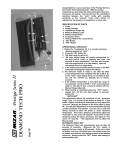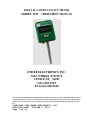
1
DIGITAL CONDUCTIVITY METER
MODEL 1152
OPERATION MANUAL
EMCEE ELECTRONICS, INC.
520 CYPRESS AVENUE
VENICE, FL 34285
(941) 485-1515
FAX 941-488-4648
The information contained in the accompanying document is proprietary and confidential, and may not be
copied in any manner whatsoever without prior written consent of Emcee Electronics, Inc. The document
and the material therein may not be used for any purpose other than that intended by Emcee Electronics,
Inc.
COPYRIGHT 1984 EMCEE ELECTRONICS, INC.
REVISION DATE: OCTOBER 3, 2001
Page 1 of 19
DIGITAL CONDUCTIVITY METER
TABLE OF CONTENTS
Page No.
1.0 Scope . . . . . . . . . . . . . . . . . . . . . . . . . . . . . . .
4
2.0 Significance . . . . . . . . . . . . . . . . . . . . . . . . . . 5
3.0 Definition . . . . . . . . . . . . . . . . . . . . . . . . . . . . 5
4.0 Summary of Method . . . . . . . . . . . . . . . . . . . . 5
5.0 Apparatus . . . . . . . . . . . . . . . . . . . . . . . . . . . . . 6
6.0 Preparation of Sample . . . . . . . . . . . . . . . . . . . 7
7.0 Test Procedure . . . . . . . . . . . . . . . . . . . . . . . .
8
8.0 Precision . . . . . . . . . . . . . . . . . . . . . . . . . . . . . 10
9.0 Battery Replacement . . . . . . . . . . . . . . . . . . .
11
10.0 Calibration . . . . . . . . . . . . . . . . . . . . . . . . . . . 12
The information contained in the accompanying document is proprietary and confidential, and may not be
copied in any manner whatsoever without prior written consent of Emcee Electronics, Inc. The document
and the material therein may not be used for any purpose other than that intended by Emcee Electronics,
Inc.
COPYRIGHT 1984 EMCEE ELECTRONICS, INC.
REVISION DATE: OCTOBER 3, 2001
Page 2 of 19
DIGITAL CONDUCTIVITY METER
TABLE OF CONTENTS
Page No.
11.0 Photographs
Figure 1 1152 with Probe attached . . . . . . .
13
Figure 2 Probe Calibration Number . . . . . .
14
Figure 3 Zero Check . . . . . . . . . . . . . . . . . .
15
Figure 4 Calibration Check . . . .. . . . . . . . . 16
Figure 5 Fuel Evaluation . . . . .. . . . . . . . . . 17
Figure 6 Conductivity Meter with Cable
Reel attached . . . . . . . . . . . . . . . . . 18
Figure 7 Battery Replacement . . . . . . . . . . . 19
Service & Warranty Policy
See Emcee Electronics, Inc Service and Warranty Manual
The information contained in the accompanying document is proprietary and confidential, and may not be
copied in any manner whatsoever without prior written consent of Emcee Electronics, Inc. The document
and the material therein may not be used for any purpose other than that intended by Emcee Electronics,
Inc.
COPYRIGHT 1984 EMCEE ELECTRONICS, INC.
REVISION DATE: OCTOBER 3, 2001
Page 3 of 19
DIGITAL CONDUCTIVITY METER
1.0 SCOPE
The Emcee Conductivity Meter is a
reliable, convenient and inexpensive
instrument for measuring the electrical
conductivity of fuels. The monitor
incorporates all solid-state components
and is completely self-contained. Several
instruments are available for various ranges.
Model
152-00-0000
152-00-0001
152-00-0003
152-00-0007
152-00-0008
Multiplier
X
X
X
X
X
1
10
100
1,000
10,000
Range
0
0
0
0
0
–
–
–
–
–
2,000 pS/m
20,000 pS/m
200,000 pS/m
2,000,000 pS/m
20,000,000 pS/m
The instrument will display units between 0
and 1999. The conductivity is equal to the
reading times the instrument multiplier and
is reported in picosiemens/meter (pS/m). The
instrument has a simple calibration and zero
check; and indicates when the conductivity
level exceeds the upper range of the meter by
displaying 1--- on the LCD display.
The information contained in the accompanying document is proprietary and confidential, and may not be
copied in any manner whatsoever without prior written consent of Emcee Electronics, Inc. The document
and the material therein may not be used for any purpose other than that intended by Emcee Electronics,
Inc.
COPYRIGHT 1984 EMCEE ELECTRONICS, INC.
REVISION DATE: OCTOBER 3, 2001
Page 4 of 19
DIGITAL CONDUCTIVITY METER
2.0 SIGNIFICANCE
Fuel products such as jet and diesel fuels
which are loaded at high pumping rates,
develop a static charge. The Emcee
Conductivity Meter measures the ability of
the fuel to dissipate that charge.
3.0 DEFINITION
The Emcee Conductivity Meter reads
conductivity in picosiemens/meter which
are equivalent to CU or Conductivity
Units.
4.0 SUMMARY OF METHOD
The Emcee Conductivity Meter uses a probe
consisting of two concentric stainless steel
electrodes. When the probe is immersed in
fuel, a constant voltage is applied to the
electrodes. This results in an electrical
current which is amplified and indicated on
the meter.
The information contained in the accompanying document is proprietary and confidential, and may not be
copied in any manner whatsoever without prior written consent of Emcee Electronics, Inc. The document
and the material therein may not be used for any purpose other than that intended by Emcee Electronics,
Inc.
COPYRIGHT 1984 EMCEE ELECTRONICS, INC.
REVISION DATE: OCTOBER 3, 2001
Page 5 of 19
DIGITAL CONDUCTIVITY METER
5.0 APPARATUS
5.1 The Emcee Conductivity Meter with Fuel
Probe is shown in Figure 1. The meter is a
hand held, battery operated portable
instrument.
5.2 The controls shown in Figure 1 consist
of a measure switch and a calibrate switch.
5.3 Figure 2 shows the location of the
probe calibration number.
5.4 Figure 3 shows the instrument zero
check.
5.5 Figure 4 shows the instrument
calibration check.
5.6
Figure 5 shows a typical fuel test.
The information contained in the accompanying document is proprietary and confidential, and may not be
copied in any manner whatsoever without prior written consent of Emcee Electronics, Inc. The document
and the material therein may not be used for any purpose other than that intended by Emcee Electronics,
Inc.
COPYRIGHT 1984 EMCEE ELECTRONICS, INC.
REVISION DATE: OCTOBER 3, 2001
Page 6 of 19
DIGITAL CONDUCTIVITY METER
5.7 The Accessory Cable Kit shown in
Figure 6 includes a portable reel with
a 50' cable . This kit enables the
operator to connect the probe to the
50' cable for use in a large tank. The
kit also is supplied with a grounding
cable for attachment between the
conductivity meter and tank ground.
6.0 PREPARATION OF SAMPLE
The sample container (preferably a one liter
metal container) should be cleaned with a
solvent and rinsed with the fuel to be
tested. After the sample for test has been
withdrawn, wait approximately two minutes for
charges in the fuel to dissipate.
The information contained in the accompanying document is proprietary and confidential, and may not be
copied in any manner whatsoever without prior written consent of Emcee Electronics, Inc. The document
and the material therein may not be used for any purpose other than that intended by Emcee Electronics,
Inc.
COPYRIGHT 1984 EMCEE ELECTRONICS, INC.
REVISION DATE: OCTOBER 3, 2001
Page 7 of 19
DIGITAL CONDUCTIVITY METER
7.0 TEST PROCEDURE
7.1 Attach probe to bottom connector on
conductivity meter.
7.2 Depress MEASURE switch (M) with probe
OUT of fuel sample. Reading should be 000
+/- 001 in approximately 3 seconds (Figure
4). If reading is outside limits, remove
probe and recheck zero by depressing MEASURE
switch.
7.2.1 If zero adjustment is okay without
probe but not when probe is attached, the
probe should be thoroughly rinsed with
isopropyl alcohol followed by reagent grade
toluene and allowed to air dry before
retesting for zero.
7.2.2 If the reading is outside of limits
with the probe removed, perform calibration
procedure outline in Section 10.0.
7.3 Depress CALIBRATE switch (C) with
probe OUT of fuel sample. After 3 seconds,
reading should be 10 times the probe
calibration number +/- 005 (Figure 4).
The information contained in the accompanying document is proprietary and confidential, and may not be
copied in any manner whatsoever without prior written consent of Emcee Electronics, Inc. The document
and the material therein may not be used for any purpose other than that intended by Emcee Electronics,
Inc.
COPYRIGHT 1984 EMCEE ELECTRONICS, INC.
REVISION DATE: OCTOBER 3, 2001
Page 8 of 19
DIGITAL CONDUCTIVITY METER
SAMPLE
Probe No. = 40
Meter Reading = 400 +/-
5 or 395 to 405
7.4 Insert probe in fuel to upper holes
and depress MEASURE switch. Report displayed
reading times multiplier after 3 seconds for
stabilization. (Due to the polarization of
the fuel sample the apparent reading will
continue to change. Only the reading 3
seconds after depressing the MEASURE switch
is correct).
Note: If a “1” is displayed on the left side
of the display, the conductivity level
exceeds the upper range of the meter.
The information contained in the accompanying document is proprietary and confidential, and may not be
copied in any manner whatsoever without prior written consent of Emcee Electronics, Inc. The document
and the material therein may not be used for any purpose other than that intended by Emcee Electronics,
Inc.
COPYRIGHT 1984 EMCEE ELECTRONICS, INC.
REVISION DATE: OCTOBER 3, 2001
Page 9 of 19
DIGITAL CONDUCTIVITY METER
8.0 PRECISION
The electrical parameters are factory
calibrated to 1% of reading. However, due to
fuel measurement characteristics, the
repeatability and reproducibility limits are
as follows:
PS/M
50
100
150
200
250
300
400
REPEATABILITY
REPRODUCIBILITY
4
6
8
9
10
11
5%
12
18
23
27
30
34
10%
Limits Applicable at Room Temperature only.
Precision based on ASTM Round Robin test of
standard 0 - 2,000 pS/m meter.
The information contained in the accompanying document is proprietary and confidential, and may not be
copied in any manner whatsoever without prior written consent of Emcee Electronics, Inc. The document
and the material therein may not be used for any purpose other than that intended by Emcee Electronics,
Inc.
COPYRIGHT 1984 EMCEE ELECTRONICS, INC.
REVISION DATE: OCTOBER 3, 2001
Page 10 of 19
DIGITAL CONDUCTIVITY METER
9.0 BATTERY REPLACEMENT
9.1 The Model 1152 Conductivity has an
internal battery checking circuit. If
batteries are weak the meter will read for a
short time and shut itself off. If batteries
are too low the unit will not turn on.
9.2 When battery replacement is indicated
remove the 4 screws holding the back plate
exposing the battery housing at the top of
the meter.
9.3 Remove the 2 screws on the battery
housing and set the housing cover to one
side (Figure 7).
9.4 Observe the polarity markings and insert
three new batteries as shown in Fig. 7.
Battery replacement must be (3) 6 volt
Alkaline Neda 1414A (A-544). Any other
battery replacement will invalidate the
Intrinsically Safe Rating.
9.5 Replace back panel and check zero and
calibration.
The information contained in the accompanying document is proprietary and confidential, and may not be
copied in any manner whatsoever without prior written consent of Emcee Electronics, Inc. The document
and the material therein may not be used for any purpose other than that intended by Emcee Electronics,
Inc.
COPYRIGHT 1984 EMCEE ELECTRONICS, INC.
REVISION DATE: OCTOBER 3, 2001
Page 11 of 19
DIGITAL CONDUCTIVITY METER
10.0 CALIBRATION
10.1 If either ZERO or CALIBRATE is outside
the limits listed in 7.2 or 7.3 the following
steps should be completed.
10.2
Remove the probe.
10.3 Insert a small screwdriver into the
hole marked ZERO while depressing the MEASURE
switch. Adjust the control until the display
reads 000 +/- 001.
10.4 While depressing the CALIBRATE switch,
insert a small screwdriver into the CALIBRATE
hole and adjust for 10 times the probe
calibration number +/- 002.
10.5 Attach the probe and depress the
MEASURE switch. The reading should be
000 +/- 001. If zero adjustment is okay
without probe but not when probe is
attached the probe should be thoroughly
rinsed with isopropyl alcohol followed by
reagent grade toluene and allowed to air dry
before retesting for zero.
The information contained in the accompanying document is proprietary and confidential, and may not be
copied in any manner whatsoever without prior written consent of Emcee Electronics, Inc. The document
and the material therein may not be used for any purpose other than that intended by Emcee Electronics,
Inc.
COPYRIGHT 1984 EMCEE ELECTRONICS, INC.
REVISION DATE: OCTOBER 3, 2001
Page 12 of 19
DIGITAL CONDUCTIVITY METER
Figure 1
The information contained in the accompanying document is proprietary and confidential, and may not be
copied in any manner whatsoever without prior written consent of Emcee Electronics, Inc. The document
and the material therein may not be used for any purpose other than that intended by Emcee Electronics,
Inc.
COPYRIGHT 1984 EMCEE ELECTRONICS, INC.
REVISION DATE: OCTOBER 3, 2001
Page 13 of 19
DIGITAL CONDUCTIVITY METER
Figure 2
The information contained in the accompanying document is proprietary and confidential, and may not be
copied in any manner whatsoever without prior written consent of Emcee Electronics, Inc. The document
and the material therein may not be used for any purpose other than that intended by Emcee Electronics,
Inc.
COPYRIGHT 1984 EMCEE ELECTRONICS, INC.
REVISION DATE: OCTOBER 3, 2001
Page 14 of 19
DIGITAL CONDUCTIVITY METER
Figure 3
The information contained in the accompanying document is proprietary and confidential, and may not be
copied in any manner whatsoever without prior written consent of Emcee Electronics, Inc. The document
and the material therein may not be used for any purpose other than that intended by Emcee Electronics,
Inc.
COPYRIGHT 1984 EMCEE ELECTRONICS, INC.
REVISION DATE: OCTOBER 3, 2001
Page 15 of 19
DIGITAL CONDUCTIVITY METER
Figure 4
The information contained in the accompanying document is proprietary and confidential, and may not be
copied in any manner whatsoever without prior written consent of Emcee Electronics, Inc. The document
and the material therein may not be used for any purpose other than that intended by Emcee Electronics,
Inc.
COPYRIGHT 1984 EMCEE ELECTRONICS, INC.
REVISION DATE: OCTOBER 3, 2001
Page 16 of 19
DIGITAL CONDUCTIVITY METER
Figure 5
The information contained in the accompanying document is proprietary and confidential, and may not be
copied in any manner whatsoever without prior written consent of Emcee Electronics, Inc. The document
and the material therein may not be used for any purpose other than that intended by Emcee Electronics,
Inc.
COPYRIGHT 1984 EMCEE ELECTRONICS, INC.
REVISION DATE: OCTOBER 3, 2001
Page 17 of 19
DIGITAL CONDUCTIVITY METER
Figure 6
The information contained in the accompanying document is proprietary and confidential, and may not be
copied in any manner whatsoever without prior written consent of Emcee Electronics, Inc. The document
and the material therein may not be used for any purpose other than that intended by Emcee Electronics,
Inc.
COPYRIGHT 1984 EMCEE ELECTRONICS, INC.
REVISION DATE: OCTOBER 3, 2001
Page 18 of 19
DIGITAL CONDUCTIVITY METER
Figure 7
The information contained in the accompanying document is proprietary and confidential, and may not be
copied in any manner whatsoever without prior written consent of Emcee Electronics, Inc. The document
and the material therein may not be used for any purpose other than that intended by Emcee Electronics,
Inc.
COPYRIGHT 1984 EMCEE ELECTRONICS, INC.
REVISION DATE: OCTOBER 3, 2001
Page 19 of 19