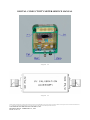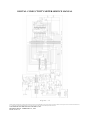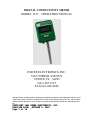
1
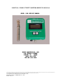
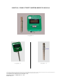
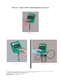
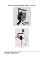
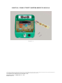
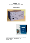
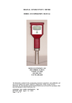
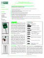
Emcee Electronics, Inc.
520 Cypress Avenue * Venice, Florida 34285
EMCEE
EMCEE Model 1152 DIGITAL CONDUCTIVITY METER
DIGITAL
(ASTM Standard Test Method D 2624)
CONDUCTIVITY
METER
convenient
reliable
accurate
measurement
of
electrical
conductivity
Model 1152 Meter
Cable Reel Kit
Detachable Probe
l Continuous standard electrical conductivity range from 0 to 1999 in increments of 1
picosiemen per meter (pS/m)
l Available in other standard and non-standard conductivity ranges
l Large digital, liquid crystal display
l Reliable advanced integrated circuit design technology
l Self check calibration with field adjustment capability
l Automatic over range and low battery indication
l Capable of storage tank and tanker truck measurement with the use of a short cable or cable reel kit
l Powered by 3 readily available alkaline batteries
l Electronics housed in a rugged cast aluminum case coated with solvent resistant paint equipped
with a detachable stainless steel probe
l Approved intrinsically safe design for use in hazardous environments by Underwriters Laboratories
(UL) U.S, (UL) Canada and LCIE (Europe)
APPLICATIONS
The Model 1152 Digital Conductivity meter
provides a measurement of electrical
conductivity of fluids in conductivity units (CU),
which are defined as picosiemens per meter in
ASTM D 2624. The rugged Electro/mechanical
design of the Model 1152 meter facilitates ease
of use for both laboratory and field applications.
Initially the meter was designed and developed
for safety reasons to measure the electrical
conductivity of hydrocarbon fuels, particularly
jet fuels. Subsequently, The meter was modified
with other conductivity ranges to accommodate
measurement of a variety of fluids for use
in many different applications.
Specifications:
Safety – Hydrocarbon fuels typically have low
electrical conductivity and consequently, are
susceptible to retaining a static charge. Static
charges are induced, especially, when the fuel is
pumped at high rates through filters. Due to the
relatively low conductivity, the static charge
does not readily dissipate and is retained for a
considerable period of time. This condition can
result in an explosion and/or fire. Since
conductivity is a function of temperature, it is
very important to record the fuel temperature at
which the measurement was performed.
Safety
Ground:
Banana jack on electronics assy.
Power:
Battery, 3 each, 6 volt alkaline
Process Controls – In addition to safety reasons,
electrical conductivity of fluids can be monitored
for process control. Proper addition and mixing of
various ingredients can be monitored at different
stages of production. These applications are not
limited to hydrocarbons, but have been expanded
to other products; such as paints, solvents, inks,
and other non-organic items. The stainless steel
probe is relatively unaffected by most acidic and
caustic solutions.
Range:
0 – 1999 pS/m
Resolution: 1 pS/m
Accuracy: 2% of reading ± 1 pS/m
Over-Range
Indicator: “1” on left side of display
Calibration: Internal source, field adj.
Controls:
Display:
2 Pushbuttons, “M” (measure)
& “C” (calibration)
Liquid crystal, 3 ½ digits,
½ inch (.27 cm) high
Op Temp
Range:
Carrying
Case:
32° to 165° F (0° to 75° C)
Hard, solvent resistant,
molded plastic
Theory of Operation – The EMCEE Model 1152
meter consists of an electronics assembly and a
detachable stainless steel probe. The probe, which is
similar to a capacitor having concentric electrodes, is
immersed into the fluid, up to the set of holes closet to
the electronics assembly. Depressing the “M”
pushbutton causes a relatively small direct current to
flow through the fluid between the electrodes. The
current is amplified in the electronics assembly and is
displayed on the liquid crystal display in picosiemens
per meter (pS/m).
Phone: (941) 485-1515 * Fax: (941) 488-4648 * E-Mail: [email protected]
DIGITAL CONDUCTIVITY METER SERVICE MANUAL
MODEL 1152 SERV I CE MANUAL
EMCEE ELECTRON I CS , I NC .
520 CYPRESS AVENUE
VEN I CE , FL
34285
( 941 ) 485 - 1515
FAX 941 - 488 - 4648
The information contained in the accompanying document is proprietary and confidential, and may not be copied in any manner whatsoever without prior written consent of Emcee Electronics,
Inc. The document and the material therein may not be used for any purpose other than that intended by Emcee Electronics, Inc.
COPYRIGHT 2002 EMCEE ELECTRONICS, INC.
REVISION DATE: FEBRUARY 23, 1996
PAGE 1 OF 14
DIGITAL CONDUCTIVITY METER SERVICE MANUAL
TABLE OF CONTENTS
PAGE
1.0
GENERAL DESCRIPTION . . . . . . . . . . . . . . . . . 3
2.0
TEST EQUIPMENT REQUIREMENTS . . . . . . . . . . . . . 3
3.0
PRELIMINARY CALIBRATION CHECK . . . . . . . . . . . . 3
4.0
BATTERY REPLACEMENT . . . . . . . . . . . . . . . . . 4
5.0
CIRCUIT DESCRIPTION . . . . . . . . . . . . . . . . . 4
6.0
TROUBLE SHOOTING CHART
7.0
CALIBRATION . . . . . . . . . . . . . . . . . . . . . 6
8.0
TEST PROCEDURE
9.0
PARTS LIST
10.0
. . . . . . . . . . . . . . . 6
. . . . . . . . . . . . . . . . . . . 7
. . . . . . . . . . . . . . . . . . . . . 8
ILLUSTRATIONS
FIGURE
FIGURE
FIGURE
FIGURE
FIGURE
FIGURE
FIGURE
FIGURE
FIGURE
FIGURE
FIGURE
FIGURE
1
2
3
4
5
6
7
8
9
10
11
12
METER AND PROBE . . . .
PROBE ATTACHMENT . . . .
PROBE CALIBRATION NO. .
OPERATING POSITION . . .
CALIBRATION MODE . . . .
MEASURE MODE . . . . . .
ACCESSORY CABLE REEL . .
REEL - METER ATTACHMENT
METER INTERNAL VIEW . .
PC BOARD ASSEMBLY . . .
CALIBRATION ACCESSORY .
SCHEMATIC DIAGRAM . . .
.
.
.
.
.
.
.
.
.
.
.
.
.
.
.
.
.
.
.
.
.
.
.
.
.
.
.
.
.
.
.
.
.
.
.
.
.
.
.
.
.
.
.
.
.
.
.
.
.
.
.
.
.
.
.
.
.
.
.
.
.
.
.
.
.
.
.
.
.
.
.
.
.
.
.
.
.
.
.
.
.
.
.
.
.
.
.
.
.
.
.
.
.
.
.
.
. 9
. 9
. 9
.10
.10
.10
.11
.11
.12
.13
.13
.13
SERVICE AND WARRANTY POLICY
See Service & Warranty Manual
The information contained in the accompanying document is proprietary and confidential, and may not be copied in any manner whatsoever without prior written consent of Emcee Electronics,
Inc. The document and the material therein may not be used for any purpose other than that intended by Emcee Electronics, Inc.
COPYRIGHT 2002 EMCEE ELECTRONICS, INC.
REVISION DATE: FEBRUARY 23, 1996
PAGE 2 OF 14
DIGITAL CONDUCTIVITY METER SERVICE MANUAL
1.0
GENERAL DESCR I PTI ON
1.1 The Emcee Digital Conductivity Meter model 1152 as shown in Figure 1 is
a hand held, battery operated, instrument for determining the conductivity of
fuel samples. Technically, the instrument is a high range ohmmeter capable
of reading between 500 megohms (2000 CU) and infinity (0 CU).
1.2 The controls as shown in Figure 1 consist of a pushbutton switch marked
M (measure) and a pushbutton switch marked C (calibrate).
1.3 Figure 2 shows the instrument with the probe attached and ready for fuel
test.
1.4 Figure 6 shows the instrument in operation with the probe in a fuel
sample.
1.5 The Accessory Cable Kit is shown in Figure 7 and 8. With this reel the
instrument can be used to test fuel in a large storage tank.
1.6 Figure 10 shows the instrument with the back removed, and the plug in
pre-amp and analog to digital PC boards removed.
1.7
2.0
2.1
Figure 11 shows the CU Substitution Box for complete calibration.
TEST EQU I PMENT REQU I REMENTS
CU Substitution Box
2.2
Digital Voltmeter, 10 megohm impedance 0-1 volt +/- .001 0-20 volt
+/- .01.
3.0
3.1
PREL I M I NARY CAL I BRATI ON CHECK
Attach probe to bottom connector on the conductivity meter.
3.2 Depress measure switch (marked M). The display should indicate 000 +/001 after 3 seconds. If the display does not indicate 000 +/- 001 remove the
probe and recheck for zero. If the meter will zero without the probe but not
with the probe, the probe should be rinsed with isopropyl alcohol and allowed
to air dry before retesting. If the meter will not zero without probe,
proceed to calibration procedure.
3.3 Depress calibration switch (marked C). The display should
indicate the number on the probe (Figure 3) times 10 +/- 005.
Example:
Probe No. = 42
Display
= 415 – 425
The information contained in the accompanying document is proprietary and confidential, and may not be copied in any manner whatsoever without prior written consent of Emcee Electronics,
Inc. The document and the material therein may not be used for any purpose other than that intended by Emcee Electronics, Inc.
COPYRIGHT 2002 EMCEE ELECTRONICS, INC.
REVISION DATE: FEBRUARY 23, 1996
PAGE 3 OF 14
DIGITAL CONDUCTIVITY METER SERVICE MANUAL
4.0
BATTERY REPLACEMENT
4.1 The model 1152 Conductivity Meter has an internal battery checking
circuit. If batteries are weak the meter will read for a short time and shut
itself off. If batteries are very low the unit will not turn on.
4.2 When battery replacement is indicated remove the 4 screws holding the
back plate exposing the battery housing at the top of the meter.
4.3 Remove the 2 screws on the battery housing and set housing cover to one
side (Figure 10).
4.4 Observe the polarity markings and insert three new batteries as shown in
Figure 10. Battery replacement must be (3) 6 volt Alkaline Nema 1414A Emcee
P/N 152-90-5341. Any other battery replacement will invalidate the CSA and
UL Intrinsically Safe Rating.
4.5
5.0
Replace back panel, check zero and calibration.
C I RCU I T DESCR I PTI ON
5.1 Power Supply The model 1152 Digital Conductivity Meter uses (3) A-554 6
volt batteries as a single 18 volt power source. Depressing either the
measure or calibrate switches provides power to op amp 1 via D(1) or D(2).
Op amp 1A compares the battery voltage to a positive output at 6 volt zener
reference (ZD-1) and provides a positive output at pin 1 if the battery
voltage is above 13 volts. This insures adequate voltage for good regulation
via VR-1. VR-1 provides a +10 volt (pin 1) and a +5 volt (pin 2) output in
reference to pin 4. The +5 volt (pin 2) output in reference to pin 4. The
+5 volt output is buffered with op amp 1B. The 0 level reference voltage is
developed using the output on op amp 1B pin 7. From this reference point we
now have a +5 volt source and a -5 volt source.
The 0 reference voltage is not attached to the case. Resistors R-15 and R-16
make up a voltage divider to provide a -1 volt source which is tied to the
case. The -1 volt becomes the bias voltage for the fuel probe.
5.2 CALIBRATE REFERENCE - The calibrate voltage is supplied by Q-1 and is
adjustable from 0 to -1 volt. Q-1 is biased on in a saturation mode via R-14
when the calibrate switch is depressed. The collector output is divided by
R-21 and R-20 and the adjustable voltage is passed on to the pre-amp. When
the measure switch is depressed R-13 reverse biases Q-1 and turns Q-1 off.
This action guarantees a 0 volt potential to the pre-amp calibrate input.
The information contained in the accompanying document is proprietary and confidential, and may not be copied in any manner whatsoever without prior written consent of Emcee Electronics,
Inc. The document and the material therein may not be used for any purpose other than that intended by Emcee Electronics, Inc.
COPYRIGHT 2002 EMCEE ELECTRONICS, INC.
REVISION DATE: FEBRUARY 23, 1996
PAGE 4 OF 14
DIGITAL CONDUCTIVITY METER SERVICE MANUAL
5.3 Pre-Amp PC Board - P/N 152-04-0000 The pre-amp board is a separate plugin PC board. Due to the extreme high impedance of the circuit, this board is
very sensitive to humidity. After manufacture, this board is coated with a
conformal coating to reduce outside humidity effects. Since this coating
cannot be removed, the components on this board should not be replaced. Any
failure of the pre-amp board requires a new board assembly. The operation of
this board, however, is to develop a current from the -1 volt bias through
the fuel sample to the op amp pin 2. Pin 2 is maintained at 0 volts via the
positive feedback through R3. With no fuel between the probe electrodes the
pre-amp output should be zero. This is adjusted with zero adjust
potentiometer R-19. During the calibrate period the negative voltage from R20 provides the bias source to the pre-amp and a calibrate reference can be
set.
5.4 A-D Converter PC Board - P/N 152-05-0000 The A-D converter assembly is
a plug-in PC board. The converter is basically a 0 - 1.999 volt., 3 digit
voltmeter. The reference voltage for setting the A-D gain is adjusted by
setting R-18 for approximately 1.0 volts. The final adjustment for this
potentiometer, however, is dependent on R-3 tolerance and variations in the
probe constant. The pre-amp output is fed to the A-D converter which has an
automatic zero adjustment, therefore, any output from the amp can be directly
monitored. The A-D converter directly drives the liquid crystal display
located on the display PC board. The A-D board can be factory repaired.
5.5 Display PC Board P/N 152-03-0000 The display board includes the power
regulator, reference voltage supply, calibration adjustment controls, liquid
crystal display, measure and calibrate switches, and the interconnects for
the A-D and the pre-amp boards. The display board can be factory repaired.
The information contained in the accompanying document is proprietary and confidential, and may not be copied in any manner whatsoever without prior written consent of Emcee Electronics,
Inc. The document and the material therein may not be used for any purpose other than that intended by Emcee Electronics, Inc.
COPYRIGHT 2002 EMCEE ELECTRONICS, INC.
REVISION DATE: FEBRUARY 23, 1996
PAGE 5 OF 14
DIGITAL CONDUCTIVITY METER SERVICE MANUAL
6.0
TROUBLE SHOOTI NG CHART
MALFUNCTION
Meter does not zero
PROBABLE CAUSE
CORRECTIVE ACTION
Contaminated Probe
Clean thoroughly
with isopropyl
alcohol and air dry
Needs zero adjustment
Adjust zero as per 7.2.
Meter reads above or
below calibration
number during CAL
check
Needs CAL adjustment
Check Pre-amp output
as per 7.0
CU reading erroneous
when CAL check is okay
Contaminated or
damaged probe.
Clean probe with
isopropyl alcohol
and air dry
Inspect probe for
physical damage.
Check electrical
characteristics as
per 7.0
No Display Indication
Lack of supply
voltage
Check connection and/or
replace batteries
MEASURE/CAL switch
defective
Replace Display PC Bd.
P/N 152-03-0000
A-D Converter
defective
Replace A-D PC Bd.
P/N 152-05-0000
+/- 5 Supply In-op
Replace Display PC Bd.
P/N 152-03-0000
7 . 0 CAL I BRATI ON
7.1 With the back panel removed set R-18 (case hole marked CAL) to
approximately mid scale. The exact setting is not important at this time,
however, the voltage at A-15 should be approximately 1.0 volts above the zero
reference (A-14).
7.2 Remove the probe if attached and depress the measure switch (M).
R-19 (case hole marked ZERO) for a display of 000 +/- 1.
Adjust
The information contained in the accompanying document is proprietary and confidential, and may not be copied in any manner whatsoever without prior written consent of Emcee Electronics,
Inc. The document and the material therein may not be used for any purpose other than that intended by Emcee Electronics, Inc.
COPYRIGHT 2002 EMCEE ELECTRONICS, INC.
REVISION DATE: FEBRUARY 23, 1996
PAGE 6 OF 14
DIGITAL CONDUCTIVITY METER SERVICE MANUAL
7.3 Attach the CU substitution box directly to the conductivity meter using
the 500 CU position.
7.4 Depress the measure switch (M) and adjust R-18 (CAL) for a display
reading of 500 +/- 1.
7.5 Remove the substitution box and repeat the zero adjustment (7.2) if
necessary. If zero adjustment is necessary repeat 7.3 and 7.4 after
readjusting zero.
7.6 Attach the CU substitution box to the conductivity meter using the 100
CU position.
7.7 Depress the measure switch (M) and read the display for linearity.
display should read 100 +/- 1. If the display is outside of tolerance
recheck zero and 500 CU positions.
The
7.8 Remove the plug from the unmarked hole in the case (between the ZERO and
CAL holes) to access R-20 (CAL reference).
7.9 Depress the calibrate switch (C) and adjust R-20 (Cal reference voltage)
for a display or 400 +/- 1.
7.10 Replace the plug removed in step 7.8 (no additional adjustment of R-20
is necessary).
7.11 The instrument is now electrically standardized and should read ZERO =
000 +/- 001, CAL = 400 +/- 001, 500 CU BOX = 500 +/- 001 and 100 CU BOX = 100
+/- 001.
7.12 The meter is then adjusted to the probe for proper fuel measurements.
Identify the probe constant by locating the number stamped on the probe (Fig.
3). Multiply that number by 10 and adjust R-18 (CAL) for that number.
Example:
Probe No. = 42 x 10 = 420
CAL adjust to 420 +/- 001
7.13 The meter is now properly calibrated for fuel measurements.
section 8.0 for operating procedure.
8.0
8.1
Refer to
TEST PROCEDURE
Attach probe to bottom connector on the conductivity meter.
8.2 Depress measure switch (M) with probe OUT of fuel sample. Reading
should be 000 +/- 001 in approximately 3 seconds (Figure 4). If reading is
outside limits remove probe and recheck zero by depressing measure switch.
8.2.2 If zero reading is outside of limits with probe removed, perform
calibration procedure outline in section 7.0.
The information contained in the accompanying document is proprietary and confidential, and may not be copied in any manner whatsoever without prior written consent of Emcee Electronics,
Inc. The document and the material therein may not be used for any purpose other than that intended by Emcee Electronics, Inc.
COPYRIGHT 2002 EMCEE ELECTRONICS, INC.
REVISION DATE: FEBRUARY 23, 1996
PAGE 7 OF 14
DIGITAL CONDUCTIVITY METER SERVICE MANUAL
8.3 Depress Calibrate switch (C) with probe OUT of fuel sample. After 3
seconds reading should be 10 times the probe calibration number +/- 005
(Figure 5).
Example:
Probe No. = 40
Meter Reading = 400 +/- 5 or 395 to 405
8.4 Insert probe in fuel to upper holes and depress measure switch. Report
reading after 3 seconds for stabilization. Due to the polarization of the
fuel sample the apparent reading will continue to change. Only the reading 3
seconds after depressing the measure switch is correct.
9.0
PARTS L I ST
Batteries
(3 required)
152-90-5341
Display PC Board
152-03-0000
Pre-Amp PC Board
152-04-0000
A-D Converter PC Board
152-05-0000
Probe
152-09-0000
The information contained in the accompanying document is proprietary and confidential, and may not be copied in any manner whatsoever without prior written consent of Emcee Electronics,
Inc. The document and the material therein may not be used for any purpose other than that intended by Emcee Electronics, Inc.
COPYRIGHT 2002 EMCEE ELECTRONICS, INC.
REVISION DATE: FEBRUARY 23, 1996
PAGE 8 OF 14
DIGITAL CONDUCTIVITY METER SERVICE MANUAL
Figure 1
Figure 2
Figure 3
The information contained in the accompanying document is proprietary and confidential, and may not be copied in any manner whatsoever without prior written consent of Emcee Electronics,
Inc. The document and the material therein may not be used for any purpose other than that intended by Emcee Electronics, Inc.
COPYRIGHT 2002 EMCEE ELECTRONICS, INC.
REVISION DATE: FEBRUARY 23, 1996
PAGE 9 OF 14
DIGITAL CONDUCTIVITY METER SERVICE MANUAL
Figure 4
Figure 5
Figure 6
The information contained in the accompanying document is proprietary and confidential, and may not be copied in any manner whatsoever without prior written consent of Emcee Electronics,
Inc. The document and the material therein may not be used for any purpose other than that intended by Emcee Electronics, Inc.
COPYRIGHT 2002 EMCEE ELECTRONICS, INC.
REVISION DATE: FEBRUARY 23, 1996
PAGE 10 OF 14
DIGITAL CONDUCTIVITY METER SERVICE MANUAL
Figure 7
Figure 8
The information contained in the accompanying document is proprietary and confidential, and may not be copied in any manner whatsoever without prior written consent of Emcee Electronics,
Inc. The document and the material therein may not be used for any purpose other than that intended by Emcee Electronics, Inc.
COPYRIGHT 2002 EMCEE ELECTRONICS, INC.
REVISION DATE: FEBRUARY 23, 1996
PAGE 11 OF 14
DIGITAL CONDUCTIVITY METER SERVICE MANUAL
Figure 9
The information contained in the accompanying document is proprietary and confidential, and may not be copied in any manner whatsoever without prior written consent of Emcee Electronics,
Inc. The document and the material therein may not be used for any purpose other than that intended by Emcee Electronics, Inc.
COPYRIGHT 2002 EMCEE ELECTRONICS, INC.
REVISION DATE: FEBRUARY 23, 1996
PAGE 12 OF 14
DIGITAL CONDUCTIVITY METER SERVICE MANUAL
Figure 10
Figure 11
The information contained in the accompanying document is proprietary and confidential, and may not be copied in any manner whatsoever without prior written consent of Emcee Electronics,
Inc. The document and the material therein may not be used for any purpose other than that intended by Emcee Electronics, Inc.
COPYRIGHT 2002 EMCEE ELECTRONICS, INC.
REVISION DATE: FEBRUARY 23, 1996
PAGE 13 OF 14
DIGITAL CONDUCTIVITY METER SERVICE MANUAL
Figure 12
The information contained in the accompanying document is proprietary and confidential, and may not be copied in any manner whatsoever without prior written consent of Emcee Electronics,
Inc. The document and the material therein may not be used for any purpose other than that intended by Emcee Electronics, Inc.
COPYRIGHT 2002 EMCEE ELECTRONICS, INC.
REVISION DATE: FEBRUARY 23, 1996
PAGE 14 OF 14
DIGITAL CONDUCTIVITY METER
MODEL 1152
OPERATION MANUAL
EMCEE ELECTRONICS, INC.
520 CYPRESS AVENUE
VENICE, FL 34285
(941) 485-1515
FAX 941-488-4648
The information contained in the accompanying document is proprietary and confidential, and may not be
copied in any manner whatsoever without prior written consent of Emcee Electronics, Inc. The document
and the material therein may not be used for any purpose other than that intended by Emcee Electronics,
Inc.
COPYR I GHT 1984 EMCEE ELECTRON I CS , I NC .
REV I S I ON DATE : OCTOBER 3 , 2001
Page 1 o f 19
DIGITAL CONDUCTIVITY METER
TABLE OF CONTENTS
Page No.
1.0 Scope . . . . . . . . . . . . . . . . . . . . . . . . . . . . . . .
4
2.0 Significance . . . . . . . . . . . . . . . . . . . . . . . . . . 5
3.0 Definition . . . . . . . . . . . . . . . . . . . . . . . . . . . . 5
4.0 Summary of Method . . . . . . . . . . . . . . . . . . . . 5
5.0 Apparatus . . . . . . . . . . . . . . . . . . . . . . . . . . . . . 6
6.0 Preparation of Sample . . . . . . . . . . . . . . . . . . . 7
7.0 Test Procedure . . . . . . . . . . . . . . . . . . . . . . . .
8
8.0 Precision . . . . . . . . . . . . . . . . . . . . . . . . . . . . . 10
9.0 Battery Replacement . . . . . . . . . . . . . . . . . . .
11
10.0 Calibration . . . . . . . . . . . . . . . . . . . . . . . . . . . 12
The information contained in the accompanying document is proprietary and confidential, and may not be
copied in any manner whatsoever without prior written consent of Emcee Electronics, Inc. The document
and the material therein may not be used for any purpose other than that intended by Emcee Electronics,
Inc.
COPYR I GHT 1984 EMCEE ELECTRON I CS , I NC .
REV I S I ON DATE : OCTOBER 3 , 2001
Page 2 o f 19
DIGITAL CONDUCTIVITY METER
TABLE OF CONTENTS
Page No.
11.0 Photographs
Figure 1 1152 with Probe attached . . . . . . .
13
Figure 2 Probe Calibration Number . . . . . .
14
Figure 3 Zero Check . . . . . . . . . . . . . . . . . .
15
Figure 4 Calibration Check . . . .. . . . . . . . . 16
Figure 5 Fuel Evaluation . . . . .. . . . . . . . . . 17
Figure 6 Conductivity Meter with Cable
Reel attached . . . . . . . . . . . . . . . . . 18
Figure 7 Battery Replacement . . . . . . . . . . . 19
Service & Warranty Policy
See Emcee Electronics, Inc Service and Warranty Manual
The information contained in the accompanying document is proprietary and confidential, and may not be
copied in any manner whatsoever without prior written consent of Emcee Electronics, Inc. The document
and the material therein may not be used for any purpose other than that intended by Emcee Electronics,
Inc.
COPYR I GHT 1984 EMCEE ELECTRON I CS , I NC .
REV I S I ON DATE : OCTOBER 3 , 2001
Page 3 o f 19
DIGITAL CONDUCTIVITY METER
1.0 SCOPE
The Emcee Conductivity Meter is a
reliable, convenient and inexpensive
instrument for measuring the electrical
conductivity of fuels. The monitor
incorporates all solid-state components
and is completely self-contained. Several
instruments are available for various ranges.
Model
152-00-0000
152-00-0001
152-00-0003
152-00-0007
152-00-0008
Multiplier
X
X
X
X
X
1
10
100
1,000
10,000
Range
0
0
0
0
0
–
–
–
–
–
2,000 pS/m
20,000 pS/m
200,000 pS/m
2,000,000 pS/m
20,000,000 pS/m
The instrument will display units between 0
and 1999. The conductivity is equal to the
reading times the instrument multiplier and
is reported in picosiemens/meter (pS/m). The
instrument has a simple calibration and zero
check; and indicates when the conductivity
level exceeds the upper range of the meter by
displaying 1--- on the LCD display.
The information contained in the accompanying document is proprietary and confidential, and may not be
copied in any manner whatsoever without prior written consent of Emcee Electronics, Inc. The document
and the material therein may not be used for any purpose other than that intended by Emcee Electronics,
Inc.
COPYR I GHT 1984 EMCEE ELECTRON I CS , I NC .
REV I S I ON DATE : OCTOBER 3 , 2001
Page 4 o f 19
DIGITAL CONDUCTIVITY METER
2.0 SIGNIFICANCE
Fuel products such as jet and diesel fuels
which are loaded at high pumping rates,
develop a static charge. The Emcee
Conductivity Meter measures the ability of
the fuel to dissipate that charge.
3.0 DEFINITION
The Emcee Conductivity Meter reads
conductivity in picosiemens/meter which
are equivalent to CU or Conductivity
Units.
4.0 SUMMARY OF METHOD
The Emcee Conductivity Meter uses a probe
consisting of two concentric stainless steel
electrodes. When the probe is immersed in
fuel, a constant voltage is applied to the
electrodes. This results in an electrical
current which is amplified and indicated on
the meter.
The information contained in the accompanying document is proprietary and confidential, and may not be
copied in any manner whatsoever without prior written consent of Emcee Electronics, Inc. The document
and the material therein may not be used for any purpose other than that intended by Emcee Electronics,
Inc.
COPYR I GHT 1984 EMCEE ELECTRON I CS , I NC .
REV I S I ON DATE : OCTOBER 3 , 2001
Page 5 o f 19
DIGITAL CONDUCTIVITY METER
5.0 APPARATUS
5.1 The Emcee Conductivity Meter with Fuel
Probe is shown in Figure 1. The meter is a
hand held, battery operated portable
instrument.
5.2 The controls shown in Figure 1 consist
of a measure switch and a calibrate switch.
5.3 Figure 2 shows the location of the
probe calibration number.
5.4 Figure 3 shows the instrument zero
check.
5.5 Figure 4 shows the instrument
calibration check.
5.6
Figure 5 shows a typical fuel test.
The information contained in the accompanying document is proprietary and confidential, and may not be
copied in any manner whatsoever without prior written consent of Emcee Electronics, Inc. The document
and the material therein may not be used for any purpose other than that intended by Emcee Electronics,
Inc.
COPYR I GHT 1984 EMCEE ELECTRON I CS , I NC .
REV I S I ON DATE : OCTOBER 3 , 2001
Page 6 o f 19
DIGITAL CONDUCTIVITY METER
5.7 The Accessory Cable Kit shown in
Figure 6 includes a portable reel with
a 50' cable . This kit enables the
operator to connect the probe to the
50' cable for use in a large tank. The
kit also is supplied with a grounding
cable for attachment between the
conductivity meter and tank ground.
6.0 PREPARATION OF SAMPLE
The sample container (preferably a one liter
metal container) should be cleaned with a
solvent and rinsed with the fuel to be
tested. After the sample for test has been
withdrawn, wait approximately two minutes for
charges in the fuel to dissipate.
The information contained in the accompanying document is proprietary and confidential, and may not be
copied in any manner whatsoever without prior written consent of Emcee Electronics, Inc. The document
and the material therein may not be used for any purpose other than that intended by Emcee Electronics,
Inc.
COPYR I GHT 1984 EMCEE ELECTRON I CS , I NC .
REV I S I ON DATE : OCTOBER 3 , 2001
Page 7 o f 19
DIGITAL CONDUCTIVITY METER
7.0 TEST PROCEDURE
7.1 Attach probe to bottom connector on
conductivity meter.
7.2 Depress MEASURE switch (M) with probe
OUT of fuel sample. Reading should be 000
+/- 001 in approximately 3 seconds (Figure
4). If reading is outside limits, remove
probe and recheck zero by depressing MEASURE
switch.
7.2.1 If zero adjustment is okay without
probe but not when probe is attached, the
probe should be thoroughly rinsed with
isopropyl alcohol followed by reagent grade
toluene and allowed to air dry before
retesting for zero.
7.2.2 If the reading is outside of limits
with the probe removed, perform calibration
procedure outline in Section 10.0.
7.3 Depress CALIBRATE switch (C) with
probe OUT of fuel sample. After 3 seconds,
reading should be 10 times the probe
calibration number +/- 005 (Figure 4).
The information contained in the accompanying document is proprietary and confidential, and may not be
copied in any manner whatsoever without prior written consent of Emcee Electronics, Inc. The document
and the material therein may not be used for any purpose other than that intended by Emcee Electronics,
Inc.
COPYR I GHT 1984 EMCEE ELECTRON I CS , I NC .
REV I S I ON DATE : OCTOBER 3 , 2001
Page 8 o f 19
DIGITAL CONDUCTIVITY METER
SAMPLE
Probe No. = 40
Meter Reading = 400 +/-
5 or 395 to 405
7.4 Insert probe in fuel to upper holes
and depress MEASURE switch. Report displayed
reading times multiplier after 3 seconds for
stabilization. (Due to the polarization of
the fuel sample the apparent reading will
continue to change. Only the reading 3
seconds after depressing the MEASURE switch
is correct).
Note: If a “1” is displayed on the left side
of the display, the conductivity level
exceeds the upper range of the meter.
The information contained in the accompanying document is proprietary and confidential, and may not be
copied in any manner whatsoever without prior written consent of Emcee Electronics, Inc. The document
and the material therein may not be used for any purpose other than that intended by Emcee Electronics,
Inc.
COPYR I GHT 1984 EMCEE ELECTRON I CS , I NC .
REV I S I ON DATE : OCTOBER 3 , 2001
Page 9 o f 19
DIGITAL CONDUCTIVITY METER
8.0 PRECISION
The electrical parameters are factory
calibrated to 1% of reading. However, due to
fuel measurement characteristics, the
repeatability and reproducibility limits are
as follows:
PS / M
50
100
150
200
250
300
400
REPEATAB I L I TY
REPRODUC I B I L I TY
4
6
8
9
10
11
5%
12
18
23
27
30
34
10%
Limits Applicable at Room Temperature only.
Precision based on ASTM Round Robin test of
standard 0 - 2,000 pS/m meter.
The information contained in the accompanying document is proprietary and confidential, and may not be
copied in any manner whatsoever without prior written consent of Emcee Electronics, Inc. The document
and the material therein may not be used for any purpose other than that intended by Emcee Electronics,
Inc.
COPYR I GHT 1984 EMCEE ELECTRON I CS , I NC .
REV I S I ON DATE : OCTOBER 3 , 2001
Page 10 o f 19
DIGITAL CONDUCTIVITY METER
9.0 BATTERY REPLACEMENT
9.1 The Model 1152 Conductivity has an
internal battery checking circuit. If
batteries are weak the meter will read for a
short time and shut itself off. If batteries
are too low the unit will not turn on.
9.2 When battery replacement is indicated
remove the 4 screws holding the back plate
exposing the battery housing at the top of
the meter.
9.3 Remove the 2 screws on the battery
housing and set the housing cover to one
side (Figure 7).
9.4 Observe the polarity markings and insert
three new batteries as shown in Fig. 7.
Battery replacement must be (3) 6 volt
Alkaline Neda 1414A (A-544). Any other
battery replacement will invalidate the
Intrinsically Safe Rating.
9.5 Replace back panel and check zero and
calibration.
The information contained in the accompanying document is proprietary and confidential, and may not be
copied in any manner whatsoever without prior written consent of Emcee Electronics, Inc. The document
and the material therein may not be used for any purpose other than that intended by Emcee Electronics,
Inc.
COPYR I GHT 1984 EMCEE ELECTRON I CS , I NC .
REV I S I ON DATE : OCTOBER 3 , 2001
Page 11 o f 19
DIGITAL CONDUCTIVITY METER
10.0 CALIBRATION
10.1 If either ZERO or CALIBRATE is outside
the limits listed in 7.2 or 7.3 the following
steps should be completed.
10.2
Remove the probe.
10.3 Insert a small screwdriver into the
hole marked ZERO while depressing the MEASURE
switch. Adjust the control until the display
reads 000 +/- 001.
10.4 While depressing the CALIBRATE switch,
insert a small screwdriver into the CALIBRATE
hole and adjust for 10 times the probe
calibration number +/- 002.
10.5 Attach the probe and depress the
MEASURE switch. The reading should be
000 +/- 001. If zero adjustment is okay
without probe but not when probe is
attached the probe should be thoroughly
rinsed with isopropyl alcohol followed by
reagent grade toluene and allowed to air dry
before retesting for zero.
The information contained in the accompanying document is proprietary and confidential, and may not be
copied in any manner whatsoever without prior written consent of Emcee Electronics, Inc. The document
and the material therein may not be used for any purpose other than that intended by Emcee Electronics,
Inc.
COPYR I GHT 1984 EMCEE ELECTRON I CS , I NC .
REV I S I ON DATE : OCTOBER 3 , 2001
Page 12 o f 19
DIGITAL CONDUCTIVITY METER
F i gure 1
The information contained in the accompanying document is proprietary and confidential, and may not be
copied in any manner whatsoever without prior written consent of Emcee Electronics, Inc. The document
and the material therein may not be used for any purpose other than that intended by Emcee Electronics,
Inc.
COPYR I GHT 1984 EMCEE ELECTRON I CS , I NC .
REV I S I ON DATE : OCTOBER 3 , 2001
Page 13 o f 19
DIGITAL CONDUCTIVITY METER
F i gure 2
The information contained in the accompanying document is proprietary and confidential, and may not be
copied in any manner whatsoever without prior written consent of Emcee Electronics, Inc. The document
and the material therein may not be used for any purpose other than that intended by Emcee Electronics,
Inc.
COPYR I GHT 1984 EMCEE ELECTRON I CS , I NC .
REV I S I ON DATE : OCTOBER 3 , 2001
Page 14 o f 19
DIGITAL CONDUCTIVITY METER
F i gure 3
The information contained in the accompanying document is proprietary and confidential, and may not be
copied in any manner whatsoever without prior written consent of Emcee Electronics, Inc. The document
and the material therein may not be used for any purpose other than that intended by Emcee Electronics,
Inc.
COPYR I GHT 1984 EMCEE ELECTRON I CS , I NC .
REV I S I ON DATE : OCTOBER 3 , 2001
Page 15 o f 19
DIGITAL CONDUCTIVITY METER
F i gure 4
The information contained in the accompanying document is proprietary and confidential, and may not be
copied in any manner whatsoever without prior written consent of Emcee Electronics, Inc. The document
and the material therein may not be used for any purpose other than that intended by Emcee Electronics,
Inc.
COPYR I GHT 1984 EMCEE ELECTRON I CS , I NC .
REV I S I ON DATE : OCTOBER 3 , 2001
Page 16 o f 19
DIGITAL CONDUCTIVITY METER
F i gure 5
The information contained in the accompanying document is proprietary and confidential, and may not be
copied in any manner whatsoever without prior written consent of Emcee Electronics, Inc. The document
and the material therein may not be used for any purpose other than that intended by Emcee Electronics,
Inc.
COPYR I GHT 1984 EMCEE ELECTRON I CS , I NC .
REV I S I ON DATE : OCTOBER 3 , 2001
Page 17 o f 19
DIGITAL CONDUCTIVITY METER
F i gure 6
The information contained in the accompanying document is proprietary and confidential, and may not be
copied in any manner whatsoever without prior written consent of Emcee Electronics, Inc. The document
and the material therein may not be used for any purpose other than that intended by Emcee Electronics,
Inc.
COPYR I GHT 1984 EMCEE ELECTRON I CS , I NC .
REV I S I ON DATE : OCTOBER 3 , 2001
Page 18 o f 19
DIGITAL CONDUCTIVITY METER
F i gure 7
The information contained in the accompanying document is proprietary and confidential, and may not be
copied in any manner whatsoever without prior written consent of Emcee Electronics, Inc. The document
and the material therein may not be used for any purpose other than that intended by Emcee Electronics,
Inc.
COPYR I GHT 1984 EMCEE ELECTRON I CS , I NC .
REV I S I ON DATE : OCTOBER 3 , 2001
Page 19 o f 19