1
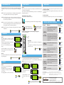
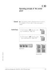
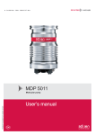
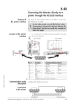
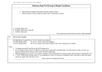
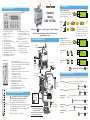
TEST CYCLES
OPERATOR INTERFACE
References
1
2
3
4
5
6
7
8
9
10
11
12
Spectro pressure status indicator
13 MAINTENANCE menu selection key
Alphanumeric display (4 lines x 20
14 OTHER menus selection key (test
characters)
mode selection, inlet VENT selection,
date / time )
Parameter function keys (1 key per
15 NEXT: next display/parameter
display line)
circular function
Modification keys (4 keys)
16 &17 Plus or minus value adjustment,
Menu selection access keys (4 keys)
parameter selection, audio volume
Control keys (4 keys)
adjustment keys
Cycle Start/Stop control key
18 RESET of previously displayed values
Sniffing mode ON/OFF control key
(cancels temporary inputs)
Autocalibration Start/Abort control key
19 Control and menu selection
Mute: Audio signal ON/OFF control key
indicators (ON when activated)
SET POINT menu selection key
SPECTRO calibration and analyzer cell
configuration menu selection key
Hard vacuum test mode
CONDENSED
MANUAL
ASM 192 T2D+
Control panel
Leak detector in stand-by mode ;
connect the part or assembly to
STDBY
STDBYTEST
be test to the detector.
8
9
10
11
12
13
14
15
16
10 -2
10 -3
1
2
3
4
5
6
7
Helium Signal digital display
Correction factor COR indicator (applied to digital display)
Zero function indicator (applied to analog + digital display)
Inlet port pressure analog display
Test cycle ON indicator (ON when activated)
Cycle Start/stop control key
Calibration in progress indicator: steady = internal autocal.,
blinking = external autocal.
Autocalibration start control key
Helium signal analogic display
Test ON indicator (Gross leak, Normal, High Sensitivity)
High Sensitivity test ON indicator
Sniffing test mode ON indicator
Inlet VENT ON indicator
Helium signal standard scale ON indicator
Helium signal Zero/Zoom scale ON indicator
Zero/Zoom ON/OFF control key
HELIUM SIGNAL ANALOG DISPLAY
10 -4
Leak detector in hard vacuum or sniffing test
mode and zero function not activated.
10 -5
10 -6
10 -7
10 -8
10 -9
10 -10
10 -11
10 -12
mbar.l/s
blinking led
= reject point
How to read the He signal analog scale?
➡ Reject point is visualized by a blinking led.
➡ If the leak value exceeds the reject point, the leds will
turned red (the blinking led will turn orange).
➡ If the leak value remains under the reject point, the
leds will remain geen.
Example: reject point = 1.10-7 mbar.l/s
F1
READY FOR CYCLE
F3
INLET ...
refer to a specific chapter of the User’s Manual.
➜
STDBY
TEST
➜
STDBY
TEST
STDBY
EndingSTDBY
a
CYCLE
cycle
➜
TEST
➜
STDBY
STDBY
For further information, please refer to the User’s Manual
supplied with your unit.
F2
TEST
F4
TEST
STDBY
Starting
a cycle STDBY CYCLE
TEST
➜
TEST
TEST
STDBY
Red leak
➜
TEST
(1)➜ value
(1)
As soon asTESTthe inlet pressure
STDBYTEST
TEST
reaches 1 mbar, the unit goes in gross
leak test mode or when the pressure
has TEST
reached 2.10-2 mbar, the unit
goes in high sensitivity test mode.
STDBY
Sniffing test mode
DETECTOR CONNECTIONS
Leak detector in stand-by mode ;
connect the long distance sniffer
probe to the quick connector.
Inlet port
DN 50
F1
READY FOR CYCLE
F3
INLET ...
STDBY
TEST
Starting sniffing test
mode
SNIFFER
F2
F4
STDBY
TEST
F1
SNIFFER
➜
F3
SNIFFING MODE
PLEASE WAIT ...
F2
F4
SNIFFER
SNIFFER
Remote control
STDBY
Ending sniffing test
mode
LDS Probe
READY FOR CYCLE
F3
INLET ...
F2
F4
A 70
Basic operation of the leak detector
C 60
ASSISTANCE TO THE TEST
Exhaust
The ASM 192 T2D+ leak detector offers to the user 5 interesting functions in order to improve test.
Air inlet
N2
Fuse of the 3
back plugs
Nitrogen
purge
ACP 28
Main
power
cord
External control
system
(I/O interface)
Memo function
Cycle end
PC
C 110
Display a greater resolution of the He signal around the reject
point.
Bargraph zoom on the reject point
B 40
C 130
Automatic control of the roughing and measure timers.
Cycle end
Printer
See the configuration ticket example
Memorization of the latest He signal measured after depressing the CYCLE key at the end of the cycle.
Memo function
Bargraph zoom on
the reject point
B 20
Controlling the detector
with a PC computer through
the RS 232 interface:
Refer to the RS 232 User’s Manual
delivered with your detector.
F1
(accessory)
Main power
switch
Remote
control
➜
C 90
Helium pollution
prevention
Device that prevents the unit from getting polluted with Helium.
Helium background
suppression
Automatic zero function.
Helium pollution prevention
Zero function
C 140
C 120
USER INTERFACE LEVEL
ZERO FUNCTION
The ASM 192 T2D+ offers 4 levels of user interface to accommodate any application
requirements. All 4 levels of user interface are acessible by means of a four-digit password.
Level 1 This level has very limited information on the alphanumeric display (LCD). This
level is generally selected for production types of applications.
Level 2 This level allows the operator to visualize some parameters without the possibility of making any changes. Some as level 1, this level is usually selected
for production types of applications.
Level 3 Some as level 2 but with the possibility to set some parameters such as test
mode, vacuum and sniffing corrections status, audio alarm and air inlet. This
level is generally selected for maintenance applications.
Purpose
The zero function offers the operator the possibility to detect small leaks that are smallers than the helium background.
The zero function could be activated manually by the operator or automatically (He
background suppression).
C 30
CALIBRATION
Internal auto-calibration on request: it can be started by the operator whenever needed (the unit has
to be off-cycle).
F1
F3
CALIBRATION VALUES
TEMPERATURE: 29°C F2
TARGET VAL:1.27E-07
PLEASE WAIT...
F4
On the digital display, the ASM 192 T2D+ He background displays.
ZERO
F3
10 -4
10 -5
READING FOR CYCLE
10 -6
10 -7
F2
10 -8
INLET ...
F4
Manual deactivation
of the zero function
1x10⁻⁸
10 -9
Analog display
- When the zero function is activated, use the He signal zero
scale.
- The He signal zero scale displays 2 leds signal centrered
around the zero value.
10 -10
AUTO CAL
Zero function
1x10⁻⁷
Calibration of the leak detector
C 70
AIR INLET
F1
F3
INLET ...
F2
F4
Air inlet
C 80
16 000 H(1)
or 2 years(2)
1 - Connect the main cable from the detector to the proper power outlet.
2 - Depress the main switch to position “I”. On the control panel, the indicators lights
flash.
3 - The following screens are shown on the LCD.
F3
READY FOR CYCLE
12 000 H(1)
10 -12
mbar.l/s
START-UP
F1
8 000 H(1)
or 1 year(2)
C 120
10 -11
PLEASE WAIT ...
ALCATEL ASM192T2D+ F2
UNIT:
mbar.l/s
SOFT: L116v1.0 r00 F4
F1
F3
PLEASE WAIT ...
HIGH.VAC PUMP:75%
ROUGHING PUMP:80%
5 - When calibration is completed, the unit is ready to start a
cycle.
F1
AUTOCAL IN PROGRESS
ELECTR.ZERO ADJUST.
F2
80
F4
F3
F1
READING FOR CYCLE
F3
INLET: vent off
22 000 H(1)
or 1 year(3)
SEE
Partial maintenance of the analyzer cell:
Replace analyzer cell filaments and collector.
Clean the analyzer cell with alcohol (this
cleaning may be necessary in case of general internal contamination creating insulating deposits).
Sniffer probe filter replacement if used.
500 000
cycles
Regrease the molecular pump MDP 5006 HDS.
Regrease the turbomolecular pump
TMP 5154.
Regrease ATP 100 pump.
Recalibration/exchange of the internal
calibrated leak.
Replace the ball bearings and the seals of
the molecular pump and turbomolecular pump.
Replace the ball bearings and the seals of
the ATP 100 pump.
Clean the valves.
CHAPTER
E 30
E 85
E 60
E 80
Contact customer
service
Pirani gauge adjustment.
Complete maintenance Dry pump (ACP 20/28).
F2
F4
4 - When the TMP pump reaches
its nominal speed, the unit autocalibrates itself.
OPERATION
Clean the vacuum lines, the valves and the
gauges with alcohol - Dust the electronic
boards and the fans - Clean filters
(inlet filters,air inlet filter)
4 000 H(1)
or
6 months(2)
2 leds
flash
C 100
INTERVAL MAINTENANCE OPERATIONS
FREQUENCY*
ZERO
10 -2
10 -3
9x10⁻⁸
External
The external auto-calibration allows direct readout in cases of operation with an auxiliary pumping system.
Purpose
The operator can connect the leak detector to
the vent air function.
The indicator “inlet: vent off” indicates that the
venting valve is not activated (= closed) at the
end of the cycle.
The setting by default is “vent off” (= valve closed).
The digital display becomes
0.0E-00. On and after this time,
it will display only He variation.
Automatic activation/deactivation of the Helium background suppression
Refer to the User’s Manual.
1.1x10⁻⁷
F1
Audio alarm
CYCLE
2x10⁻⁷
Internal
The internal calibration is automatically activated
during the start-up process. It doesn’t require any
operator action.
Thanks to the initial auto-calibration, the leak detector can be immediately operationnal.
The result of the auto-calibration process is displayed.
The audio alarm offers 2 modes of operation. They are both linked to the zero function.
Zero function not activated
The audio alarm start when the He signal exceeds a fixed set point: this set point is
programmable.
Zero function activated
The audio alarm is modulated with respect to the position of the helium background.
Manual activation of the zero function
Connect the part or installation to be tested.
Level 4 This level allows access to all parameters and is generally used for settings all
the parameters.
User interface level presentation
AUDIO ALARM
E 30
E 40
E 45
E 70
E 30
E 40
E 45
Contact customer
service
E 85
*Service intervals: The service intervals given are for
(1) running time
(2) running time or storage applications and work rates which conform to the normal
operating conditions. If the machine is operating under more
(3) storage
difficult conditions they can be shortened.
F2
STDBY
TEST
F4
Starting up/Switching off the leak detector
STDBY
C 50
TEST
Alcatel Vacuum Technology France
98, avenue de Brogny BP 2069
74009 Annecy cedex France
Tel. (33) 4 50 65 77 77 Fax. (33) 4 50 65 77 89
GB 01516 - Ed.01 February 02