1
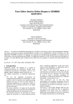
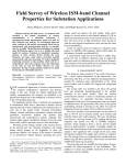
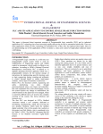
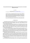
ANALELE UNIVERSITĂŢII “EFTIMIE MURGU” REŞIŢA ANUL XXI, NR. 3, 2014, ISSN 1453 - 7397 Gheorghe Hazi, Aneta Hazi Considerations on Numerical Protections for Induction Motors Connected in MV Industrial Power Systems The paper presents some considerations on the calculation and adjustment of numerical protections used for induction motors connected in MV (6-10 kV) power systems. It examines the setting for the next protections: overcurrent, earth fault and thermal overload. An example for a 6 kV motor, 200 kW is presented. Keywords: induction motors, motor protection, overcurrent protection, software protection 1. Introduction Large scale production of the numerical protection relays for the induction motors offer a wide range of protection functions such as (ANSI codes are listed in parentheses): Directional phase overcurrent (67) and phase overcurrent (50/51) Directional earth fault (67N) and earth fault (50N/51N) Directional active overpower (32P) Phase undercurrent (37) Negative sequence / unbalance (46) Excessive starting time, locked rotor (48/51 LR) Thermal overload (49RMS) Setting this protection requires a detailed analysis of the characteristics of the motor. Also, the correct setting of the motor protection must take into account the characteristics of the supply power system, particularly, by the treatment of the neutral for power system. Several papers deal with this issue. The paper [2] presents a combined protection approach for induction motors. To achieve this, the current, voltage, speed and temperature values of the induction motor were measured with sensors and processed automatically with the developed software in C. The processes were then inserted into a microcontroller. The paper [3] presents a 189 combined protection approach for induction motors. To achieve this, the electrical values of the induction motor were measured with sensitivity ±1% through a data acquisition card and processed with software developed in Visual C++. An on line protection system for induction motors was achieved easily and effectively. The paper [4] presents a new method to discriminate over currents caused by fault from transformer energizing and induction motors starting. In this method, a criterion function is introduced in terms of variation of fundamental component amplitude of current signal over consecutive segments. The criterion function is then used in over-current protection, and faults are precisely discriminated from non-fault switching. The paper [8] presents the MM200 motor protection and control system designed specifically for low-voltage motor applications. The paper [9] discusses updates in the existing 49 thermal model implementation. Also discussed are resistive temperature detector biasing, resistive temperature detector voting and the role of transducers in the modern motor relay. This paper analyzes how to configure protection for a medium power motor. 2. The Influence of Power System Power system characteristics influence the following sizes: Value of the phase to phase fault current given by its short circuit power. Value and circulation of earth fault currents. Earth fault network behavior depends crucially on the treatment of neutral. If the neutral is isolated or treated by arc suppression coil (BS), when an earth fault occurs, will circulate only capacitive current and, possibly, inductive current gave by Petersen coil. These currents are low, usually under the value of maximum load currents. If the neutral is treated by low resistor (R), when an earth fault occurs, including in the motor stator, will circulate high fault currents of the order of 300600 A, depending on the value of the resistor. In case of neutral treated by Petersen coil, operation selective of the earth fault protection depends on the existence of a high value resistors which to be connected in parallel with coil after fault earth. To analyze specifically those mentioned above we consider a squirrel cage induction motor connected as in the diagram in figure 1. Sequence impedances to the fault K1: Y Y Y Z 1 Z ds Z T || L 6 La Z L 6 || L 6 Z L 6 m 2 2 2 Y Y Y Z 01 Z BPN 3 Z BS || R || 0 L 6 0 La Z 0 L 6 || 0 L 6 Z 0 L 6 m 2 2 2 190 (1) 2 185 mm , 10 km 25 MVA ~ 6 kV CONSUMER 2 185 mm , 1,85 km 110/6 kV 6 kV BS 110 kV K2 BPN K1 R 3M ~ 2 70 mm , 30 m 6 kV SEPAM M40 Figure 1. Single line diagram for supply of the motor Figures 2 and 3 shows the positive and zero sequence the diagrams for a fault to the motor terminals. YLa Z +s Substation E ZT Other cables YL6 2 YL6 2 E - phase voltage substation 110 kV Z +s- system impedance Z T - transformer 110/22, 25 MVA Induction motor Z L6m I + terminal Z L6 U+ Z L6 ,YL6 YLa - other cables kV, 185 mmp, 10 km Figure 2. Positive sequence diagram for anθ fault at the motor terminals, 200 kW, 6 kV 191 Y0La Z 0s ZT Substation 110 kV Z 0L6 Z BPN 3R Y0L6 2 Z 0L6m I0 Y0L6 2 U0 3ZBS Z 0s - system impedance R - high value resistance 346 Z 0L6 , Y0L6 - cable 6 kV, 185 mmp, 1.85 km Z 0T - transformer 110/22 kV, 25 MVA Y0La - other cables 6 kV, 185 mmp, 10 km Z BPN - nul coil Z BS - arc suppression coil Z 0L6m - cable 6 kV, 70 mmp, 300 m Figure 3. Zero sequence diagram for an fault at the motor terminals, 200 kW, 6 kV Sequence impedances to the fault K2: Y Y Y Z 2 Z ds Z T || L 6 La Z L 6 || L 6 2 2 2 (2) Y 0 L6 Y 0 L 6 Y 0 La Z 02 Z BPN 3 Z BS || R || Z 0 L 6 || 2 2 2 Table 1 presents the fault current given by the supply network of the motor, for the defects to its terminals. Table 1. Calculation of fault currents in the supply network of the motor 6 kV No. Parameter Calculation UM Value Observarelation tions 1. Minimum threeA 7581.96 c=1.0 c U n phase short circuit I k 31min 3 Z 1 current, K1 2. Maximum threephase short circuit current, K1 I k 31max c U n 3 Z 1 192 A 8340.16 c=1.1 3. 4. 5. 6. 7. Minimum twophase short circuit current, K1 Maximum twophase short circuit current, K1 Earth fault current in the motor without resistor R connected in parallel with BS Earth fault current in the motor with resistor R connected in parallel with BS Earth fault current in the motor, isolated neutral I k 21min c U n 2 Z 1 A 6566.17 c=1.0 I k 21 max c U n 2 Z 1 A 7222.79 c=1.1 I k1 3 U n 2 Z 1 Z 01 A angle 2.47 -81.32 º Z01 does not contain R I k1 3 U n 2 Z 1 Z 01 A angle 10.48 -12.76º Z01 contain R I k1 3 U n 2 Z 1 Z 01 A angle 16.77 89.89º Z01 contains only capacitive admittance From Table 1 it is seen that the values of the multi-phase short circuit currents are high. In reality, in case of the fault in the motor windings, the currents are smaller, but it can be provide adequate sensitivity of the overcurrent protections through appropriate choice of starting values. Instead, fault earth protection is significantly influenced by the how the neutral is treated, as follows: In case of the neutral treated by Petersen coil, without coupling resistor R in parallel (by the residual overvoltage protection of the substation 110/6 kV), the current is phase shifted by 81 ° behind the phase voltage of phase with fault and is phase shifted by about 99 ° before the zero sequence voltage. Selectivity of protection can be ensured by zero sequence voltage and by phase angle of current. It has a very small value. If the resistor R is connected in parallel with the Petersen coil, it ensures selectivity by directional earth fault, the angle between voltage and zero sequence current being about 167 °. If the neutral network is isolated, earth fault current value depends on the length of galvanically connected cables. The selectivity is ensured in this case by the value of the zero sequence voltage and by the phase current, about 90 ° behind the zero sequence voltage. If neutral is treated by low value resistor (fault current limited to 600A), an earth fault is detected by earth fault protection, ANSI code 50N/51N. 193 3. Phase overcurrent Setting adjustments takes account of characteristic the starting current. Figure 4 shows the induction motor protection characteristics. The figure shows that the current protections not need to operate to motor start. Figure 4. Protection characteristics of the asynchronous motor The adjustments of current protections are shown in Table 2. The time overcurrent protection is active for the currents greater than start current, but insensitive to the inrush current at starting (by time delay or blocking at the presence of harmonic 2 of the current). The instantaneous overcurrent protection is active for the currents higher than the surge current at starting. No Current protection 1. Delayed overcurrent protection with blocking for the harmonic 2 during starting ANSI code 51-1 I> Table 2. Setting current protections Calculation Value Delay Sensitivity relation, [A] t [s] coefficient starting current Ipp I k sens k 21 min I pp 207.04 194 0.5 k sens 31.04 1 .5 2. 3. Instantaneous overcurrent protection 51-2 I>> Negative sequence / unbalance protection 46 I2> ksig=2 ip=6.9 ur I pp ksig I n i p k sens 390.42 0.0 5.66 4 I k 2 min I pp k sens 16.46 1.5 I pp 0.2 I n 4. Earth Fault Protection Operation of this protection is based on the appearance of a zero sequence voltages of higher value (3Uf for neutral isolated or treated by Petersen coil) and the relative position of zero sequence voltage and zero sequence current. There is also the advantage that the capacitive current value generated by the cable between the location of the protection and motor is negligible. In Figure 5 are shown operating characteristics of the protection for the network with the neutral treated by arc suppression coil (with parallel resistance, 5a) and for one with the isolated neutral (5b). 5. 6. 7. 8. 9. 10. 11. 12. In the Table 3 are shown setting earth fault protection (67N) depending on how neutral treated for a SEPAM relay M41 [5], with the zero sequence current transformer type CSH, 2A. Figure 5. Configuring of the earth fault protection: a) neutral treated by arc suppression coil and resistor b) isolated neutral 195 Table 3. Setting earth fault protection (67N) depending treated No. How neutral Poz. from U0 I0s Delay treated table 1 [A] t [s] 1. Neutral treated 5 0.5·Unph 1 3 by arc suppression coil, without resistor high value, Note 1 2. Neutral treated 6 0.5·Unph 3 3 by Petersen coil, with resistor high value 3. Isolated neutral 7 0.5·Unph 3 3 on how neutral θ [°] -45 Figure 0 5a 90 5b - Unph – rating phase voltage Note 1: In the case of Petersen coils with no additional resistance, fault detection in steady state operating conditions is not possible due to the absence of active zero sequence current. The protection function uses the transient current at the beginning of the fault to ensure tripping. For the neutral treated by the resistor with low value (less applicable in our country) a fault earth leads to fault currents up to 600 A, which are detected by the earth fault protection (50N/51N). 5. Thermal Overload Most protections of type thermal image use a relationship for the dwell time of the form [1]: I 2 I 2p max p T ln (3) t T ln I 2 k I 2 max ad b where t – operating time T – time constant θ – temperature rise above ambient θad – admissible temperature rise above ambient for the load current, k·I θp – temperature rise for the specified load current, I p, before the overload occurs θmax – temperature rise for the load current, I Ib – basic load current k – constant, k > 1 196 For SEPAM M41 relay [5] equation (3) is used as: 2 I ech Es 0 I b t T ln (4) 2 I ech Es Ib where Iech equivalent current , in the case of motors with coiled rotors, which the presence of a negative sequence component, I i, increases the heat rise in the motor I ech I 2 K iI i2 (5) Ki is an adjustable factor that may have the following values: 0 - 2.25 - 4.5 – 9 (4.5 usual value) [5] Es0 - initial heat rise, used to reduce the cold tripping time Es – set point for heat rise that the protection must operate. Two set points may be set for heat rise: Es1: alarm (usually setpoint Es1=90%), Es2: tripping (usually setpoint Es2=110%). I I b max , Imax is the maximum load current in steady state (for example 1.05 Imax=In) The time constant, T, has two values: heat rise time constant, T1 and cooling time constant, T2 (figure 6). Common values are T1=15 min and T2=30 min [6]. Figure 6. Heat rise and cooling time constants Figure 7 shows the setup of this protection with SFT2841 software [7]. For example, for an overload current I=1.2, will result alarm time t alarm = 3.76 min and the trip time ttrip = 9.97 min. Tripping time at starting current 197 Ip=ip·In = 195 A is 19 s for the cold starting and 8 s at hot starting. This should be correlated with the actual starting time of machine working. Figure 7. Setting protection with SFT2841 software 6. Other Protections The relay has other protections: Excessive starting time, locked rotor, ANSI code 48/51LR. This allows for a starting current set, to limit the time allowed to operate in this mode. Undervoltage, ANSI code 27/27S. It picks up if one of the 3 phase-to-neutral or phase-to-phase voltages drops below the Us (or Vs) set point. It includes a definite time delay. Directional active overpower, ANSI code 32P. This function may be used as "reverse active power" protection against motors running like generators (for example, a outside short circuit) It picks up if the active power flowing in other direction (supplied) is greater than the P s set point. It includes a definite time delay. Phase undercurrent, ANSI code 37. It picks up when phase current drops below the Is set point. It is inactive when the current is less than 10 % of I b. It includes a definite time delay. Temperature monitoring, ANSI code 38/49T. This protection is associated with an RTD of the Pt100 platinum (100 Ω at 0 °C) or Ni 100 or Ni 120 nickel type in accordance with the IEC 60751 and DIN 43760 standards. It picks up when the monitored temperature is greater than the θ s set point. It has two independent set points: alarm set point and tripping set point. When the protection is activated, it detects whether the RTD is shorted or disconnected. 198 7. Conclusions From the above data results the following conclusions: Use of the numerical protection relays for the induction motors offer a wide range of protections that allow configuration for specific conditions of their operating. The overcurrent protection is required only for defects that generate higher currents than the starting current. Their setting must be correlated with existing starting time (direct on line starting, star-delta starting, resistance stator starting, autotransformer starting, slip ring motor starting, soft starter starting, frequency converter starting). The negative sequence protection is useful for disconnecting the motor in case of the unequal phases or two-phase operation. Earth fault protection depends on how the neutral is treated. Numerical relays provides configuration options for all variants (neutral isolated, treated with arc suppression coil with or without resistor high value, treated with resistor low value). Overload protection type of thermal image is based on the temperature given by full load current at the steady state. Experimental determination (by the manufacturer or at place of assembly) of the time constants for heating and cooling is required. There are options that can use time-current characteristic given by the manufacturer. References [1] IEC 60255-8, Thermal electrical relay, International Electrotechnical Commission, 1988. [2] Bayindir R., Sefa I., Novel approach based on microcontroller to online protection of induction motors, Energy Conversion and Management, Volume 48, Issue 3, March 2007, Pages 850–856. [3] Çolak I., Çelik H., Sefa I., Demirbaş S., On line protection systems for induction motors, Energy Conversion and Management, Volume 46, Issue 17, October 2005, Pages 2773–2786. [4] Lotfifard S., Faiz J., Kezunovic M., Over-current relay implementation assuring fast and secure operation in transient conditions, Electric Power Systems Research, Volume 91, October 2012, Pages 1–8. [5] Schneider Electric, Sepam series 40, User’s manual, 03/2011, http://www.schneider-electric.com [6] Wester C., Applying Motor Data to Setup Motor Protective Relay, GE Multilin, 2010. [7] Schneider Electric, SFT 2841 SEPAM Setting Software, V13.1, 18 MAR 2013, 38050 Grenoble Cedex 9. 199 [8] GE Multilin, MM200 - Motor Management System. Instruction manual, 215 Anderson Avenue, Markham, Ontario, Canada, http://www.GEmultilin.com. [9] Ransom D.L., Hamilton R., Extending Motor Life with Updated Thermal Model Overload Protection, IEEE Protective Relay 2011. Addresses: Prof. Dr. Eng. Gheorghe Hazi, “Vasile Alecsandri” University of Bacău, Calea Mărăşeşti, nr. 157, 600115, Bacău, [email protected] Prof. Dr. Eng. Aneta Hazi, “Vasile Alecsandri” University of Bacău, Calea Mărăşeşti, nr. 157, 600115, Bacău, [email protected] 200