1
V Series Controller
Installation Instructions
Use these installation instructions to install a V Series Controller. The
controller allows the V Series electronics to be separate from a door’s
locking mechanism and to be located up to 500 feet away from the locking mechanism. The controller provides V Series electronic features for
use with electrically-controlled locking devices.
The controller is well-suited to provide access control for:
■ exit devices
■ glass doors
■ non-standard doors
■ turnstiles
■ doors controlled by electric strikes or magnetic locks
■ electrically-operated mortise or cylindrical locks.
The controller is suitable for use with interior or exterior doors. The controller has an adaptable power supply input that accepts 12 to 24 volts
AC or DC. A backup battery supports the controller’s programming in
the event of a power failure. All controller functions are shut down while
under backup power.
The main role of the controller is to control the operation of the locking
device connected to the controller. A reader can be connected to the
controller to provide a means for users to access the door controlled by
the controller.
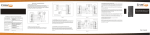
Figure 2 shows the relationship between the controller and the other
possible components in the access control system for the door.
The controller can accept a request-to-exit signal from a lock or a separate request-to-exit device, such as a button, can be connected to the
controller. When someone turns a door knob with a request-to-exit feature, or presses a request-to-exit button, the controller does not trigger
an alarm when the door is opened. If the controller is programmed for
the RQE unlock feature, the controller also unlocks the door.
A remote unlock device, such as a button, can be connected to a controller. This device can be located away from the door. When someone, such
as a receptionist, presses the remote unlock button, the controller
unlocks the door if programmed for the remote unlock feature.
The controller can monitor the door’s status. If the door is opened without use of a valid access method, the controller can trigger a door forced
alarm. The controller can monitor whether the door has been open too
long. The controller also can supervise a tamper switch, which can be
used to protect the controller enclosure or another device. The controller’s alarm output can trigger an external alerting device, such as a siren
or strobe light, or a security system.
Installation overview
Caution: To prevent damage, always wear a properly
grounded electrostatic discharge (ESD) wrist strap when
installing the controller.
1
Prepare to mount the enclosure
a Unpackage the controller.
b Check that you have the following components, in addition to these
instructions:
▲ enclosure with circuit boards and battery pack installed
▲ magnetic stripe reader (optional)
▲ keypad reader with V Series Keypad Security Device Programming
Guide (optional)
▲ proximity reader (optional)
T61920/Rev A 1768984 ER-7991-1
remote RS-232 connector (optional)
temporary access cards (for magnetic stripe and proximity readers only)
▲ V Series Controller Enclosure Drilling Template (V05).
Read these instructions carefully before you begin installation.
Note: Wire gauge and length requirements for each device to be connected to the controller are included in Figure 1.
Reference the V05 template to select a location for the controller
enclosure. Get four mounting screws suitable for the selected
mounting surface.
If you are running cables to the enclosure through the wall or ceiling,
drill any necessary cable entry holes for the cables.
Run all necessary cables to the selected mounting location.
▲
▲
c
d
e
f
2
Mount the enclosure
a Referencing the V05 template, install the four mounting screws for
the enclosure. Do not tighten the screws completely.
b If you ran cables through the wall or ceiling to the enclosure, hold
the enclosure near the selected mounting location and feed the
cables through the appropriate cable entry holes into the enclosure.
Note: In addition to the cable entry hole in the back of the enclosure
above the controller board, there are cable entry holes in the sides, top,
and bottom of the enclosure.
c With the enclosure door removed, hang the enclosure on the four
mounting screws and slide it into position so that the screws are in
the narrow part of the keyhole-shaped mounting holes. Then,
tighten the mounting screws.
3
Connect devices to the controller board
You can connect the devices listed below to the controller board. Refer
to Table 1 and to Figure 1.
■ Locking device. Use the locking device output. Set the locking
device jumper (J1).
■ Magnetic stripe or proximity card reader or keypad reader
(optional). Use the reader output, reader communications input, and
reader power output. Set DIP switches 1, 2, 3, 4, and 5. Also, set the
power jumper (J3).
Note: Standard readers are the Mercury Security, MR–5 (magnetic
stripe card reader), the Essex KTP–71212XX (keypad reader), the Motorola ASR603, and the HID MB–5398 (proximity readers). To determine
whether another reader is compatible with the controller, refer to the
specifications provided in Table 1 for the reader output, reader communications input, and reader power output.
■ Door status switch and/or door latch monitor (optional). Use the
door status/latch monitor input.
■ Request-to-exit device (optional). Use the request-to-exit input.
■ Remote unlock device (optional). Use the remote unlock input.
■ Tamper switch (optional). Use the tamper switch input.
■ Security system or alerting device (optional). Use the alarm output.
■ Remote RS-232 connector (optional). Use the controller board’s
RS-232 connector.
■ Shielding & grounding. Connect all cable shielding to the grounding screw located to the right of the circuit board. Then connect the
grounding screw connection to earth ground.
BEST ACCESS SYSTEMS
Indianapolis, Indiana
(continued on page 4)
Table 1—Controller inputs and outputs
Input/output
Description
Related DIP switches, jumpers, and
programming tasks
Backup battery input
Input for the 4.8 volt nicad battery pack. In the event of a
power failure, the battery pack temporarily powers the microprocessor until it can properly shut down.
Before you install the controller, we recommend you charge the backup battery pack in
the controller for at least 48 hours.
Note: When changing batteries, dispose of old batteries in accordance with all federal, state, and local regulations.
Caution: After a power interruption, the backup battery pack may require 48 hours to recharge. If
another power interruption occurs within 48 hours, the controller might lose its programming.
Power input
two (2) terminals
(Polarity does not matter.)
Input for a 12 to 24 volts AC or DC at 0.75 amp power supply.
Caution: To prevent damage and injury, connect the
power supply after all other connections have been
made.
None
Alarm output
NC terminal
NO terminal
COM terminal
Relay output that can be used to signal a security system or
activate an alarm input for an alerting device such as a siren,
bell, or strobe light. This output can switch up to 1 amp at
24 volts AC or DC. This output is triggered by door open too
long (DOTL), tamper, or door forced conditions.
Program the alarm output duration. For
instructions, see the V Series Intelligent Programmer Software User Manual.
Locking device output
NC terminal
NO terminal
COM terminal
Relay output used to unlock or lock an external locking device.
This output can switch up to 5 amps at 24 volts AC or DC.
To determine which terminals to use, consider how the locking
device should operate when power fails at the controller. Refer
to the appropriate table below based on whether the controller and locking device share one power supply or have two separate power supplies.
Set the locking device jumper (J1). To determine which jumper setting to use, consider
how the locking device should operate when
power fails at the controller. Refer to the
appropriate table below based on whether the
controller and locking device share one power
supply or have two separate power supplies.
Table A—Controller and locking device share one power supply
Terminals to use
Jumper setting to use
During power failure at the central controller
Locking device is fail-safe Locking device is fail-secure
NC & COM
NO & COM
de-energized
de-energized
Table B—Controller and locking device have two separate power supplies
Terminals to use
Jumper setting to use
Reader output
RLED terminal
GLED terminal
SOUND terminal
During power failure at the central controller
Fail-safe locking device should be
Fail-secure locking device should be
locked
unlocked
locked
unlocked
NC & COM
NO & COM
NO & COM
NC & COM
de-energized
energized
de-energized
energized
Note: A fail-safe locking device locks when power is applied, and unlocks when power is removed. A fail-secure
device unlocks when power is applied, and locks when power is removed.
Output that supplies 10 mA at 5 volts, and provides signals cor- Set controller DIP switch 1.
responding to the V Series Electronic Lock’s green LED, red LED,
Note: For readers with a single two-color
and sounder. This output can be connected to the reader and
LED, set DIP switch 1 ON. For readers with two
used to provide visual and/or audio user feedback similar to
separate LEDs, set DIP switch 1 OFF.
the feedback provided by the electronic lock. For a description,
The table below shows the recommended consee the V Series Service Manual.
The table below shows the recommended color wiring connec- troller DIP switch settings for the standard
readers—the Mercury Security, MR–5, the
tions for the standard readers—the Mercury Security, MR–5
(magnetic stripe card reader), the Essex KTP–71212XX (keypad Essex KTP–71212XX, the Motorola ASR603, and
the HID MB–5398.
reader), and the Motorola ASR603, and the HID MB–5398
Reader
S1
(proximity readers).
Mercury Security ON
Term
Mercury
Essex
Motorola HID
Essex
OFF
RLED
None
Blue
None
Brown
Motorola
ON
GLED
Brown
Brown
Brown
Orange
HID
ON
SOUND Orange
None (sounder Blue
Yellow
For the Mercury Security, MR–5 (magnetic
gives keypad
stripe card reader), set DIP switch 2 on the
feedback only)
reader itself to OFF.
BEST ACCESS SYSTEMS
Indianapolis, Indiana
2
Table 1—Controller inputs and outputs
Related DIP switches, jumpers, and
programming tasks
Input/output
Description
Reader communications
input
DATA terminal
STRB terminal
CARDPR terminal
Input for an ABA signal consisting of a data signal and a strobe
signal (and sometimes a card present signal).
Note: The strobe signal sometimes is called “clock.”
The table below shows the wiring connections for the standard
readers—the Mercury Security, MR–5, the Essex
KTP–71212XX, the Motorola ASR603, and the HID MB–5398.
Term
Mercury
Essex
Motorola HID
DATA
Green
Green
Green
Green
STRB
White
Red
White
White
CARDPR None
None
None
None
PWR
Red
Orange
Red
Red
GND
Black
Yellow
Black
Black
Set controller DIP switches 2, 3, 4, and 5.
See Table C for the switch settings for various
reader types.
Reader power output
PWR terminal
GND terminal
Output that provides 5 volts DC at up to 100 mA, or 12 or
24 volts DC at up to 200 mA, to the reader. The table above
shows the wiring connections for the standard readers.
Note: The standard readers — the Mercury Security, MR–5,
the Essex KTP–71212XX, the Motorola ASR603, and the
HID MB–5398 — operate at the optimal voltage — 12 volts.
Set the power jumper (J3).
Caution: To prevent damage to the
reader, set the power jumper (J3)
before supplying power to the controller.
For the standard readers, set the jumper to the
12 V position.
RS-232 connector
Connector for use when programming the controller using a
PC. To program the controller, connect a remote RS-232 connector to this connector. Then, connect the PC to the remote
connector using either the laptop cable or the palmtop cable.
Alternately, connect a PC directly to this connector using either
the laptop cable or the palmtop cable. See Figure 3.
When programming using the RS-232 connector, DIP switch 6 must be set to the OFF position.
Door status/latch monitor
input
DOOR terminal
GND terminal
Input that signals the status (open or closed) of the door. To
monitor door status, you can use a door contact and/or a latch
switch. Use the door contact to monitor whether the door is
closed. Use the latch switch to monitor whether the lock’s latch
is out (secure) or in (not secure). Thus one or both of these sensors can be used to determine whether the door has been
secured.
When used in combination, the door contact and latch switch
must be either both normally closed contacts or both normally
open contacts. If both contacts are normally closed, wire the
devices in series. If both contacts are normally open, wire the
devices in parallel.
Program the controller to generate door forced
alarms and/or door open too long alarms. For
instructions, see the V Series Intelligent Programmer Software User Manual.
Request-to-exit input
RQE terminal
GND terminal
Input for a switch contact that signals the controller to unlock
the door and/or to not trigger an alarm while the door is
unlocked or exited. If the lock has a built-in request-to-exit output, connect that output here. Or you can connect a separate
request-to-exit device, such as a button.
Program the controller for request-to-exit
operation. For instructions, see the V Series
Intelligent Programmer Software User Manual.
Remote unlock input
REMOTE terminal
GND terminal
Input for a switch contact that signals the controller to unlock
the door. A remote unlock device, such as a button, can be connected to this input. This device can be located away from the
door. When someone, such as a receptionist, presses the button, the input signals the controller to unlock the door.
Program the controller for remote unlock operation. For instructions, see the V Series Intelligent Programmer Software User Manual.
Tamper switch input
TMPR terminal
GND terminal
Input for a switch contact that signals the controller when a
tamper switch has been triggered. You can use a tamper
switch to protect the controller enclosure or another device.
None
Handheld connector
Connector for programming the controller using a handheld
terminal. Connect the handheld cable to this connector.
Note: This connector also can be used when programming
using a PC. Connect the PC-to-lockset adapter cable to this
connector.
When programming using the handheld connector, DIP switch 6 must be set to the ON position. After programming, set switch 6 back to
the OFF position.
T61920/Rev A 1768984 ER-7991-1
BEST ACCESS SYSTEMS
Indianapolis, Indiana
3
4
Connect the power supply to the controller board
Caution: To prevent damage and injury, connect the power
supply after all other connections have been made.
Connect the 12 to 24 volts AC or DC at 0.75 amp power supply to the
controller board’s power input. Refer to Table 1 and to Figure 1.
5
Specifications
Enclosure size: 12″ x 12″ x 3″
Normal operating temperature: –40°F to +158°F (–40°C to +70°C)
Storage temperature: –58°F to +176°F (–50°C to +80°C)
Relative humidity: 10% to 90% non-condensing for indoor
installations
Finish the Installation
a When you’ve finished making connections to the controller board,
dress all cables so they do not interfere with installation of the enclosure door.
b Install the enclosure door.
Programming the controller
You can use either a V Series Handheld Terminal or an IBM-compatible
PC running the V Series Intelligent Programmer Software (IPS) to program the controller.
To program the controller using a handheld terminal:
a Connect the handheld cable to the controller’s handheld connector,
shown in Figure 1.
b Place controller DIP switch 6 in the ON position.
c Follow the instructions in the V Series Handheld Terminal User Manual.
d When you’ve finished programming the controller, place DIP
switch 6 back in the OFF position.
To program the controller using a PC running the IPS:
a Connect the palmtop cable or laptop cable to the controller’s remote
RS-232 connector or to the RS-232 connector on the controller
board, shown in Figure 1.
b Follow the instructions in the V Series Intelligent Programmer Software User Manual.
BEST ACCESS SYSTEMS
Indianapolis, Indiana
4
{
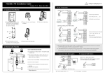
Figure 1—Controller board wiring diagram
BEST ACCESS SYSTEMS
Indianapolis, Indiana
Locking device Reader
output
output
See Note A
Table A and
Table B.
See Note A.
{
Alarm
output
{
NC & COM
de-energized
NO & COM
de-energized
NC & COM
de-energized
Note A: To determine the appropriate wire
gauge and length, refer to Minimum
Gauge Wire Chart for Lock Circuits.
Terminals to use
Jumper setting to use
See Note B.
NO & COM
de-energized
NC & COM
energized
Note B: We recommend you use 22 AWG
shielded cable no more than 500' long.
NO & COM
energized
©
OFF
ON
OFF
Note C
Note C
Motorola Weigand
HID ABA reader with HID ABA card
HID ABA reader with HID 26 bit Weigand card Note C
HID ABA reader with HID 37 bit Weigand card Note C
OFF
ON
OFF
OFF
OFF
OFF
OFF
OFF
OFF
S5
S6
ON
Note D
Note D
Note D
Note D
Note D
Note D
Note D
Note C: Use switch 1 to set the LED and sounder output for various readers. See Reader Output
on page 2.
Note D: Use switch 6 for handheld terminal communications only. Leave the switch in the off
position normally.
ON
OFF
OFF
OFF
OFF
ON
OFF
ON
ON
OFF
Do not move switches 1–5
ON
Note C
Handheld Terminal communications
OFF
Note C
Essex, KTP-71212XX
Motorola ABA
ON
ON
Mercury Security, MR-5
ON
S3
ON
S2
S1
Note C
Reader
S4
Connect to remote RS-232 connector. Or, to communicate
with a PC, connect to palmtop cable or laptop cable.
RS-232
connector
Connect all cable shields to the grounding
screw. Then connect the grounding screw
to earth ground.
Grounding
screw
Request-to-exit
unlock input
Door status/
latch monitor
input
Tamper switch
input
Remote unlock
input
Spare input
See Note B.
To communicate with a
handheld, connect to
handheld cable.
DIP switches See Table C.
Handheld
connector
Table C—Standard reader DIP switch settings
Reader power
jumper
Caution: To avoid injury, do not
touch the heat sink. It may be hot.
Reader Reader
communi power
cations output
input
During power failure at the central controller
Fail-safe locking device should be
Fail-secure locking device should be
locked
unlocked
locked
unlocked
Table B—Controller and locking device have two separate power supplies
Terminals to use
Jumper setting to use
During power failure at the central controller
Locking device is fail-safe Locking device is fail-secure
Table A—Controller and locking device share one power supply
Caution: To prevent damage and
injury, connect the power supply
after all other connections have
been made.
Connect to 12 to 24 V AC/DC
power supply. See Note A.
Power input
Locking device jumper
See Table A and B
{
{
{
{
Caution: To prevent damage,
always wear a properly grounded
electrostatic discharge (ESD)
wrist strap when installing the
controller.
Backup battery
input
{
{
{
{
{
{
T61920/Rev A 1768984 ER-7991-1
Figure 2—Block diagram
Figure 3—RS–232 wiring diagram
BEST ACCESS SYSTEMS
Indianapolis, Indiana