1
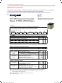
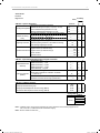
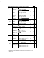
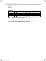
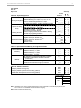
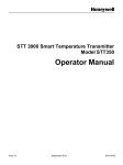
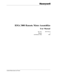
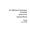
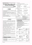
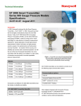
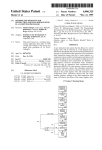
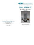
Smart Temperature Transmitter Series STT 3000, Model STT350 Specifications EN0I-5222 September 2010 Introduction Honeywell’s microprocessor based STT350 Smart Temperature Transmitter converts a primary sensor input into an output signal for a conventional 4 to 20mA, two wire loop. This universal temperature input model readily accepts signals from a wide variety of industry standard thermocouples or resistance temperature detectors (RTDs) as well as a straight millivolt or Ohms sensor. Its output signal is either proportional to the measured variable or linearized to temperature, and is transmitted in either an analog 4-20mA format or a digital DE protocol format for direct digital integration to the TPS® control system. You easily select the analog or digital format for the output Figure 1 – STT350 Transmitter in Field Mount Housing. signal transmission through the Smart Field Communicator® (SFC) which is the common hand-held operator interface for Smart transmitter personality with local or remote interfacing means significant manpower efficiency improvements in commissioning, start-up, and ongoing maintenance functions. Automatically provides true differential temperature measurement of thermocouple or RTD inputs by individual linearization of each sensor reading and then computing the difference. Suitable for true 4-wire Pt100 measurement (or 3- or 2wire). Standard digital cold-junction compensation function FISCO approved. provides accurate and reliable temperature Write protect link included to safeguard configuration settings. Designed to be in compliance with EMC requirements and is CE-Marked. adding typical A/D and D/A converter inaccuracies Includes sensor break detection on all input wires. Added Smart features include reading of the highest Post read validation of the measured signal before providing fresh output. Supports dual thermocouple sensor inputs for redundant sensor operation. and Ohms. Integral analog or digital indicating meter option Suitable for DIN rail mounting or remote field mounting Surge/lightning protection options can be installed internally in housing or externally in conduit. our SmartLine™ Transmitters. All configuration, operation and communication functions are under the control of the STT350’s microprocessors and are implemented through the SFC. Features Single model accepts input signals from a choice of primary sensors to satisfy varying applications requirements with minimum transmitter inventory. measurement over a wide ambient operating range. Direct digital integration with TPS system provides local measurement accuracy to the system level without and lowest inputs, external cold junction compensation temperature at an isothermal block and engineering units displayed in degrees C, F, K, or R plus millivolt in a flameproof housing. HFS Catalog_Without Tab_HighRes.pdf 1635 6/8/2011 12:42:14 PM STT 3000 Smart Temperature Transmitter 2 Description This lets you initiate configuration and maintenance The STT350 transmitter is suitable as a direct replacement functions at locations remote from the transmitter itself. The for any conventional temperature transmitter in use today. SFC is also fully compatible with all other Honeywell Its memory contains the characteristics of most commonly SmartLine Transmitters. The transmitter module can also used temperature sensors. This means that you can use be installed on a standard DIN rail (to EN50022) or remotely the SFC to configure the transmitter for any of these mounted in a flameproof housing designed for either sensors and it will automatically correct for their associated surface or two-inch pipe-stand mounting. Transmitters can non-linearities. You make all transmitter adjustments and be pre-configured at the factory to your exact specifications diagnostic checks through an SFC connected anywhere or they will be shipped with factory default configuration — across the 4-20mA wire route. ready to accept your own configuration. Figure 2—Block Diagram HFS Catalog_Without Tab_HighRes.pdf 1636 6/8/2011 12:42:14 PM STT 3000 Smart Temperature Transmitter 3 Performance Under Rated Conditions Input Type Digital Accuracy for Maximum Range Limits % of Max. Span Maximum Range Limits °C °F Digital Accuracy for Normal Range Limits °C °F Normal Range Limits °C Standards °F RTD Pt 100 0,01 -200 to 850 -328 to 1562 0,1 0,18 -200 to 450 -328 to 842 IEC 751:1986 (a=0.00385) Pt 200 0,01 -200 to 850 -328 to 1562 0,1 0,18 -200 to 450 -328 to 842 IEC 751:1986 (a=0.00385) Pt 500 0,02 -200 to 850 -328 to 1562 0,1 0,18 -200 to 450 -328 to 842 IEC 751:1986 (a=0.00385) Pt 100J 0,01 -200 to 640 -328 to 1184 0,1 0,18 -200 to 450 -328 to 842 JISC 1604-81 (a=0.00392) Ni 50 0,04 -80 to 150 -112 to 302 0,1 0,18 -50 to 150 -58 to 302 Honeywell Type A Cu 10 0,37 -20 to 250 -4 to 482 1,0 1,8 -20 to 250 -4 to 482 General Electric Cu 25 0,19 -20 to 250 -4 to 482 0,5 0,9 -20 to 250 -4 to 482 General Electric B 0,14 200 to 1820 392 to 3308 1,0 1,8 550 to 1820 1022 to 3308 IEC 584-1 (ITS-90) C 0,03 0 to 2300 32 to 4172 0,6 1,08 0 to 1650 32 to 3002 IPTS 68 D 0,03 0 to 2300 32 to 4172 0,6 1,08 330 to 1370 626 to 2498 IPTS 68 E 0,04 -200 to 1000 -328 to 1832 0,2 0,36 0 to 1000 32 to 1832 IEC 584-1 (ITS-90) J 0,04 -200 to 1200 -328 to 2192 0,2 0,36 0 – 800 32 to 1472 IEC 584-1 (ITS-90) K 0,04 -200 to 1370 -328 to 2498 0,3 0,54 -120 to -191 to 2498 IEC 584-1 (ITS-90) T/C: 1370 N 0,06 -200 to 1300 -328 to 2372 0,3 0,54 0 to 1300 32 to 2372 IEC 584-1 (ITS-90) R 0,09 -50 to 1760 -58 to 3200 0,5 0,9 500 to 1760 932 to 3200 IEC 584-1 (ITS-90) S 0,08 -50 to 1760 -58 to 3200 0,5 0,9 500 to 1760 932 to 3200 IEC 584-1 (ITS-90) T 0,14 -250 to 400 -418 to 752 0,2 0,36 -100 to 400 -148 to 752 IEC 584-1 (ITS-90) NiNiMoly 0,03 0 to 1300 32 to 2372 0,3 0,54 780 to 1300 1436 to 2372 G.E. (IPTS – 68) Radiamatic 0,6 420 to 1800 788 to 3272 0,7 1,26 780 to 1800 1436 to 2372 Honeywell (RH) Millivolts 0,01 -20 to 120 mV 8µV -10 to 45 mV Ohms 0,01 0 to 2000 0,15 0 to 2000 Note that the Accuracy values are available merely by selecting the sensor type and range (i.e. without user calibration). Improvements of up to 2 times can be obtained for the accuracy by calibrating to the required LRV/URV values. All STT350 units pass through 20 hours of Environmental Stress Screening (ESS) by fast cycling between -40 and +85°C to ensure maximum product reliability. During this ESS process, the ambient temperature compensation coefficients are determined for individual units and burned in transmitter memory to provide maximum performance over a wide range of operating conditions. HFS Catalog_Without Tab_HighRes.pdf 1637 6/8/2011 12:42:14 PM STT 3000 Smart Temperature Transmitter 4 Specifications Operating Conditions Parameter Reference conditions Rated Condition Operative Limits Transportation and Storage Ambient Temperature 23°C ± 2 -40 to 85 -40 to 85 * -50 to 100 73°F ± 4 -40 to 185 -40 to 185 -58 to 212 Rack Mounting %RH 10 to 55 5 to 95 5 to 100 5 to 100 Mounted in EP %RH 10 to 55 5 to 100 5 to 100 5 to 100 Humidity Housing Supply Voltage, Current and Load Resistance Voltage Range : 10.8 to 42.4 Vdc at the transmitter terminals Vibration Maximum of 4g over 15 to 200Hz. (restricted to 3g with indication meter) Shock Maximum of 40g Current Range : 3.6 to 21.8 mA Load Resistance : 0 to 1450 Ohms (as shown in Fig 3) Output D/A Accuracy ±0.025% of span Cold Junction Accuracy ± 0.25°C Total Reference Accuracy In Analog Mode = Digital Accuracy of input + Output D/A Accuracy + CJ Accuracy (T/Cs only) In Digital Mode = Digital Accuracy of input + CJ Accuracy (T/Cs only) (example: transmitter operating in Analog Mode with Pt100 sensor and 0 to 200°C Total Reference Accuracy = 0.1 + ((200/100) x 0.025) = 0.15°C Digital Ambient Temperature Effect RTDs or Ohms : 0.029% of reading (per 10°C change from 20°C reference) T/Cs or mV : 0.042% of reading Cold Junction Rejection Effect 60:1 for changes from 23°C ambient Output D/A Ambient Temperature Effect 0.045% of span per 10°C change Total Output Ambient Temperature Effect (ATE) Digital ATE + Output D/A ATE + CJ ATE (T/Cs only) In Analog Mode = In Digital Mode Digital ATE + CJ ATE (T/Cs only) = Power Supply Voltage Effect 0.005% of span per Volt Parameter Description Adjustment Range No limits to adjustments within the Maximum range except minimum span limit of 1 engineering unit e.g. 1°C Output (2 Wire) 4-20mA or Honeywell DE digital protocol Extended range: 3.8-20.8mA. Fail safe modes <3.8mA or 21.8mA Damping Time Constant Thermocouple Burnout Adjustable from 0 to 102 seconds digital damping Burnout detection is user selectable Upscale or downscale with critical status message Input to Output Galvanic Isolation Meets dielectric strength test of 1400Vac rms (50/60Hz) 2000Vdc for 1 minute Series Mode Rejection 40dB (100 to 1) for 50 or 60Hz ±0.5Hz (with internal software filter set to local power line frequency) HFS Catalog_Without Tab_HighRes.pdf 1638 6/8/2011 12:42:14 PM STT 3000 Smart Temperature Transmitter 5 Parameter Description EMC Compliance In compliance with 89/336/EEC, Electromagnetic Compatibility (EMC) Directive RFI Rejection ±0.1% of span at 30V/m over 20 to 1,000MHz in explosion-proof housing with shielded cables Update Rate 2 to 5 measurements per second depending on input variation Response Time 1.5 seconds to 90% of final step value Stability/Time Drift 0.05% of maximum span per year. Auto calibration against internal reference every second. Short term Operative Limit of –50°C (-58°F) Physical Mounting, Construction and Approvals Parameter Description Mounting DIN rail (top hat or G rail) Field Mount Housing with surface mounting or 2-inch pipe mounting (IP 66/NEMA 4X Rating) Field Mount Housing meets the applicable requirements of NEMA 7 and 9 Wiring Screw Terminals - M3.5x6.7mm nickel coated brass Accepts up to 12AWG, 16AWG recommended Net Weight Transmitter for DIN rail mount - 0.5kg (1.1 pounds) Transmitter in EP or XC housing - 1.6kg (3.6 pounds) Transmitter + indicator in housing - 2.4kg (5.2 pounds) Materials of construction Transmitter module - Aluminum housing with baked on Polyester paint cover - Noryl terminal block. EP housing - Aluminum housing with baked on epoxy-polyester hybrid paint cover (beige) XC housing - Aluminum housing with baked on 2 coats epoxy resin cover (beige) ST02 housing - Aluminum housing with baked on 2 coats epoxy resin cover (red) Dimensions See Fig 4 Sensor/Cable Entry (EP, XC or ST02 Housing) 1/2 inch NPT electrical connection with optional adapters for M20x1.5, or 3/4 inch NPT Safety Approvals STT350 Module CENELEC Intrinsically Safe Ex ia IIC T4/T5/T6 with 30V/100mA/1.2W barrier (T4/T5/T6 = -20 to +80/+50/+40 °C ambient) CSA Intrinsically Safe Class I, Div.1, Groups A to D FM Intrinsically Safe Class I, II, III, Div. 1, Groups A to G Non-incendive Class I, Div. 2, Groups A to D Suitable for Class II, III, Div. 2, Groups F and G Russian Certificate of pattern Approval No 332 of 18/10/94 IEC 68 and IEC 801 Additional Approvals with EP, XC or ST02 Housings HFS Catalog_Without Tab_HighRes.pdf 1639 With or Without Integral Meter Zone 2: T6, 28V/22mA Cenelec Flame Proof Ex d IIC T6 CSA Explosion Proof Class I, II, III, Div. 1, Groups B to G FM Explosion Proof Class I, II, III, Div. 1, Groups B to G Without Integral Meter FM Explosion Proof Class I, II, III, Div. 1, Groups A to G 6/8/2011 12:42:14 PM STT 3000 Smart Temperature Transmitter 6 Physical Mounting, Construction and Approvals Parameter Description Surge/Lightning Internal SP Selection 10 kA peak current (8/ 20 µs waveform), 10kV peak Voltage (10/50 µs waveform) Protection Options External LP Selection 10 kA peak current (10/ 20 µs waveform), 500A peak Current (10/1000 µs waveform) Thermowell & Probe Availability STT350 can be supplied integrally mounted with any of the previously listed standard resistance temperature devices (RTDs) and thermocouple (T/Cs) elements. Probe Types: 1/4" Rigid or spring loaded RTDs or T/Cs in Inconel or Stainless Steel sheaths in standard lengths from 3" to 24" (other lengths by request) Standard or heavy duty service Locally mounted to the STT350 housing or remotely mounted into explosion-proof mounting heads. With (or without) probe lag hardware : Hex nipple, Straight nipple or Double lag and Union connections Single or dual element availability; grounded or ungrounded T/Cs Additionally, the following types of Thermowells can also be provided as an integral thermal solution : Thermowell Materials: Carbon Steel, 304SS, 316SS, 316L SS, 446SS, Hastelloy B, Hastelloy C, Monel, Inconel 600 (other materials by request) Thermowell Types: Threaded well, Flanged well, or Socket well, (with or without thermowell lag extensions) Flange Types: Raised Face, Flat Faced and Ring Type Joint flange availability in 1", 1.5", 2" or 3" sizes Flange Ratings: ANSI 150#, 300#, 600# and 1500# ratings NOTE: A minimum of 250 Ohms of loop resistance is required to support communications. Loop resistance is the total of loop wiring resistance, safety barrier and receiving device input developing resistor. The triangle outlined by the heavy lines alongside shows the operating area for field wiring and barrier resistance beyond the 250 Ohms necessary for communications. If a Smart Meter is included in the loop, allow an additional 2.25 Volts for meter power. If surge lightning protection is included this adds 44 Ohms to the loop resistance; i.e., allow 1 Volt additional supply or reduced loop wiring power. HFS Catalog_Without Tab_HighRes.pdf 1640 Figure 3 — Supply Voltage versus Load Resistance 6/8/2011 12:42:15 PM STT 3000 Smart Temperature Transmitter 7 Figure 4 — STT350 Transmitter and Optional Flameproof Housing Dimensions –reference only – mm (inches) HFS Catalog_Without Tab_HighRes.pdf 1641 6/8/2011 12:42:15 PM STT 3000 Smart Temperature Transmitter 8 Model Selection Guide (34-44-16-02) Model Selection Guides are subject to change and are inserted into the specifications as guidance only. Prior to specifying or ordering a model check for the latest revision Model Selection Guides which are published at: http://hpsweb.honeywell.com/Cultures/en-US/Products/Instrumentation/ProductModelSelectionGuides/default.htm 34-44-16U-02 Issue 33 Page 1 of 4 STT 3000 Temperature Transmitter Models STT350 & STT35F Fieldbus Model Selection Guide Instructions ● Select the desired Key Number. The arrow to the right marks the selection available. ● Make one selection from each table using the column below the proper arrow. ● A dot (●) denotes unrestricted availability. A letter denotes restricted availability. ● Restrictions follow Table VII. Key Number STT35_ - I II III _ - ____ - ____ IV - _______ - V VI VII ___ - ____ - ____ KEY NUMBER Description STT350 Smart Temperature Transmitter Module (4-20mA/DE) * STT35F Fieldbus Temperature Transmitter Module * Selection Availability STT350 STT35F All modules carry the following approvals: (See Approvals Table VII for more information) All modules carry CE Mark and are in compliance with CE Mark: EN 50081-2 and 50082-2. Russian Certificate of Pattern Approval No. 2064 of Jan. 1988. * Use of STT350/35F within Class II or III, Division 1 or 2, Groups E, F and G requires the use of explosion-proof field mount housing option. TABLE I - Sensor Probe and Thermowell Accessories No Integral Sensor Probe or Thermowell Supplied 0 TABLE II - Transmitter Housing and Integral Meters (Select approval body certification in Table VII) No Housing Supplied 00 _ _ Explosion-Proof Field Aluminum with beige epoxy coating EP _ _ Mount Housing (Note 2) Integral Meter (Note 3) ● ● ● ● ● ● ● j j ● For Stainless Steel or Red Epoxy Painted Housing, select Table II EP _ _ and appropriate Table VI code. No Meter Supplied Analog Meter for Field Mount Housing Digital Meter for Field Mount Housing Fieldbus Digital Meter for Field Mount Housing TABLE III - Configuration & Tagging None - Factory Default Configuration Supplied Transmitter Configuration (see 13:STT-OE-5 for choices) Configuration Transmitter Configuration - (Fieldbus) No Tagging Requested 316 SS Wired-on Customer I.D. Tag - (4 lines, Customer Tagging 28 characters per line, customer specified information) (Note 4) 316 SS Wired-on Customer I.D. Tag (blank) _ _ 00 _ _ ME _ _ SM j _ _ FM ● 00 _ _ TC _ _ FC _ _ _ _ 00 _ _ TG ● ● ● j ● ● j _ _ TB j j Note 1: Specify 8 digit customer I.D. when probe/well selected. See Price Pages 13:TP-1 to 16 for sensor/well pricing. Note 2: With a housing, 20 characters max. of customer information is available on the nameplate at no charge. (See 13:STT-OE-5 for ordering instructions.) Note 3: Remote Meter available as Model RMA300 (See Price Page 13:RM-1.) Note 4: Replaces Selection _ _ _ _ _US HFS Catalog_Without Tab_HighRes.pdf 1642 6/8/2011 12:42:15 PM STT 3000 Smart Temperature Transmitter 34-44-16U-02 Issue 33 Page 2 of 4 Availability STT35 _ TABLE IV - Optional Equipment No Mounting Arrangement Supplied DIN Rail Mounting via 2 Clips (to Top Hat or "G" Rail) Mounting Arrangement Carbon Steel Mounting Bracket for 2" Pipe Stainless Steel Mounting Bracket for 2" Pipe No Adaptor(s) Supplied - 1/2" NPT Conduit Connection 316 SS Conduit 1/2" NPT to M20 x 1.5 1 Adaptor Adaptor for Wiring 2 Adaptors (EEx d IIC Approved) Entry 1 Adaptor 1/2" NPT to 3/4" NPT No Lightning Protection Supplied Lightning Protection External Lightning Protection - Mountable to Housing Internal Surge/Lightning Protection None English Version (for STT35F Only) Operator/User Manual English Version (for STT350 Only) (4) French Version Spanish Version TABLE V - Optional Extended Warranty Coverage & Certificates Standard Warranty Additional Warranty - 1 year Optional Extended Additional Warranty - 2 years Warranty Additional Warranty - 3 years Lifetime Warranty - 15 years No Transmitter Configuration/ Calibration Certificate Transmitter Configuration/ Calibration Certificate Optional Certificate (Note 5) 9 (D-0097-RD.A) No Certificate of Conformance/ Origin Certificate of Conformance/ Origin (D-0098-RD.A) TABLE VI - Additional Features No Selection Red Epoxy Painted Housing Cap Red Epoxy Painted Explosion-Proof Housing (Note 6) 316 Stainless Steel Explosion-Proof Housing (Note 6) 0 ● k j j ● ● ● ● ● j F ● k j j ● ● ● ● ● j _ _ _ SP _ _ _ _ _ _ _ 00 _ _ _ _ _ EF _ _ _ _ _ EN _ _ _ _ _ FR _ _ _ _ _ SP j ● j ● ● 0__ 1__ 2__ 3__ L__ _0_ ● ● ● ● ● ● ● ● ● ● ● ● _D_ ● ● __0 __C ● ● ● ● 0000 ST01 ST02 ST07 ● j g g ● j g g Selection 00 _ _ _ _ _ DR _ _ _ _ _ MB _ _ _ _ _ SB _ _ _ _ _ __0____ __1____ __2____ __3____ _ _ _ 00 _ _ _ _ _ LP _ _ ● ● ● Pricing Table A Table II Table VI EP00 EPME ST07 EPSM EPFM Note 5: Installation Guide, chosen Operator's Manuals and chosen Certificates are automatically shipped with unit. See 13:STT-OE-7 for additional manuals and alternate shipping. Note 6: Must be ordered with Table II EP _ _. HFS Catalog_Without Tab_HighRes.pdf 1643 6/8/2011 12:42:15 PM STT 3000 Smart Temperature Transmitter 10 Availability STT35 _ TABLE VII - Safety Approval Body Selection Appearing on Housing Nameplate e Approval Body Approval Type Location or Classification None No approval body certifications included Explosion-proof Class I, Div. 1, Groups A,B,C,D Dust-Ignition-proof Class II, III Div. 1, Groups E,F,G Intrinsically Safe Class I, II, III, Div. 1, Groups A,B,C,D,E,F,G Nonincendive Class I, Div. 2, Groups A,B,C,D Suitable for Class II, III, Div. 2, Groups F, G Outdoor Location Enclosure Type 4X Explosion-proof Class I, Div. 1, Groups B,C,D (with Indicato FM Approvals Dust-Ignition-proof Class II, III, Div. 1 Groups E,F,G Intrinsically Safe Class I, II, III, Div. 1, Groups A,B,C,D,E,F,G Nonincendive Class I, Div. 2, Groups A,B,C,D Suitable for Class II, III, Div. 2, Groups F, G Enclosure Type 4X Outdoor Location Intrinsically Safe Class I, II, III, Div. 1, Groups A,B,C,D,E,F,G Class I, Div. 2, Groups A,B,C,D Nonincendive Explosion-Proof Class I, Div. 1, Groups B,C,D Class II, III, Div. 1, Groups E,F,G Dust Ignition-Proof Intrinsically Safe Class I, II, III, Div. 1, Groups A,B,C,D,E,F,G Suitable for CSA Class II, III, Div. 2, Groups F, G Outdoor Location Enclosure Type 4X Intrinsically Safe Class I, II, III, Div. 1, Groups A,B,C,D,E,F,G Suitable for Class I, Div. 2, Groups A,B,C,D Intrinsically Safe, EEx ia IIC T4, T5, T6 Zone 0/1 (Module) EEx d IIC T5, T6 Enclosure Flameproof, Zone 1 rated IP 66/67 EEx nA, T5, T6, Zone 2 Non-Sparking, (Honeywell) Module to be installed in enclosure rated IP 54 ATEX* Zone 2 Selection 0 F 00 ● ● 1C f f 1J j j 1G m m 2J j j 2G m m 3S ● ● 3D j j 3N ● ● 3H j j minimum Multiple Marking**, Int. Safe, Zone 0/1, or Flameproof, Zone 1, or Non-Sparking, Zone 2 SA INMETRO (Brazil) EEx ia IIC T4, T5, T6 EEx d IIC T5, T6 EEx nA, IIC T5, T6 (Honeywell) Enclosure IP 54 minimum Instrinsically Safe, Zone 0/1 Ex ia IIC T4 (Ta = 70°C) 4S ● Flameproof BR-Ex d IIC T6, (Ta -50 to 80°C), T5, (Ta 50 to 85°C) 6D j Intrinsically Safe BR-Ex ia IIC T6, (Ta -50 to 40°C), T5, (Ta 50 to 55°C), T5, (Ta -50 to 85°C) BR-Ex ia IIC T6, (Ta -50 to 40°C), T5, (Ta 50 to 50°C), T5, (Ta -50 to 85°C) j ● 6S ● Intrinsically Safe, Zone 0/1 Ex ia llB or llC T6 (Ta = -50°C to +40°C) Ex ia llB or llC T5 (Ta = -50°C to +50°C) Ex ia llB or llC T4 (Ta = -50°C to +85°C) (Module only, IP 20) CS ● ● Flameproof, Zone 1, Intrinsically Safe, Zone 0/1 Ex d IIC T6 (Ta = -50°C to +80°C) Ex d IIC T5 (Ta = -50°C to +85°C) Ex ia llB or llC T6 (Ta = -50°C to +40°C) Ex ia llB or llC T5 (Ta = -50°C to +50°C) Ex ia llB or llC T4 (Ta = -50°C to +85°C) Enclosure IP 66/67 CA j j IECEx * See ATEX installation requirements in Operator's Manuals EN1l-6162 & EN1I-6196 ** The user must determine the type of protection required for installation of the equipment. The user shall then check the box [√] adjacent to the type of protection used on the equipment certification nameplate. Once a type of protection has been checked on the nameplate, the equipment shall not be reinstalled using any of the other certification types. HFS Catalog_Without Tab_HighRes.pdf 1644 6/8/2011 12:42:15 PM STT 3000 Smart Temperature Transmitter 11 34-44-16U-02 Issue 33 Page 4 of 4 RESTRICTIONS Restriction Letter f g j k m Notes: Table II II II II Available Only With Selection EP _ _ EP _ _ EP _ _ 0000 Table II II Not Available With Selection _ _ SM, _ _ FM EP _ _ See 13:STT-9 and User's Manual for part numbers. See 13:STT-OE-5 for OMS Order Entry Information including tagging, transmitter configuration, manuals, certificates, drawings and SPINS. To request a quotation for a non-published "special", fax RFQ to Marketing Applications at 602 313-6155. Ordering Example: STT350-0-EPME-0000-0000000-000-0000-0000 HFS Catalog_Without Tab_HighRes.pdf 1645 6/8/2011 12:42:15 PM STT 3000 Smart Temperature Transmitter 12 Warranty/Remedy Honeywell warrants goods of its manufacture as being free of defective materials and faulty workmanship. Contact your local sales office for warranty information. If warranted goods are returned to Honeywell during the period of coverage, Honeywell will repair or replace without charge those items it finds defective. The foregoing is Buyer's sole remedy and is in lieu of all other warranties, expressed or implied, including those of merchantability and fitness for a particular purpose. Specifications may change without notice. The information we supply is believed to be accurate and reliable as of this printing. However, we assume no responsibility for its use. While we provide application assistance personally, through our literature and the Honeywell web site, it is up to the customer to determine the suitability of the product in the application. SmartLine™ and Smart Field Communicator® are registered trademarks of Honeywell. For More Information Learn more about how STT 3000 Smart Temperature Transmitter can provide true differential temperature measurement, visit our website www.honeywell.com/ps/hfs or contact your Honeywell account manager. Honeywell Process Solutions 1860 West Rose Garden Lane Phoenix, Arizona 85027 EN0I-5222 September 2010 © 2010 Honeywell International Inc. Tel: 1-800-423-9883 or 1-800-343-0228 www.honeywell.com/ps HFS Catalog_Without Tab_HighRes.pdf 1646 6/8/2011 12:42:15 PM STT 3000 Smart Temperature Transmitter Specifications Foundation™ Fieldbus Model STT35F EN0I-6083 September 2011 Introduction Honeywell’s microprocessor based STT35F Smart Temperature Transmitters convert a primary temperature sensor input into a standard FOUNDATION™ Fieldbus output signal on a 2 wire signal plus power multidrop connection. These universal temperature input models readily accept signals from a wide variety of industry standard thermocouples (T/Cs) or resistance temperature detectors (RTDs) as well as basic milliVolt or Ohms sensors. The output signal is either proportional to the measured variable or linerarized to temperature. The STT35F output conforms to the low speed (H1) of the Figure 1 – STT35F module and Transmitter in Field Mount Housing with display indicator. Includes Flash Memory for ease of software upgrade Fieldbus Physical Layer specification IEC 61158-2 (1993). over the Fieldbus for changes or improvements in this The other protocol layers conform to the FOUNDATION emerging technology. Fieldbus section of the 8 part IEC 61158 standard. This is supported by all the worldwide instrumentation suppliers and enables multidrop field instruments to be powered via a single wire pair and communicate measurement, control, configuration and diagnostic data at 31.25kbps. Includes sensor break detection on all input wires. Configuration of the STT35F Function Blocks and the Fieldbus Application Parameters can be done with the National Instruments Configuration Toolkit or any other STT Features Single model accepts input signals from a choice of (AI), Control Bloc (PID), Resource Block (RB) and primary sensors to satisfy varying applications Transducer Block (XB). requirements with minimum transmitter inventory. Includes Link Master capability to assume Link Active Added Smart features include reading of the highest Scheduler (LAS) role of controlling the deterministic and lowest inputs, external cold junction compensation message communications in the event of primary LAS temperature at an isothermal block and engineering loss. units displayed in degrees C, F, K, or R plus milliVolt Integral Digital Meter available without the need for an and Ohms. additional bus connection or power. Fieldbus Foundation registered configurator. Includes Fieldbus Foundation standard Function blocks to ensure full interoperable operation - Analog Input Post read validation of the measured signal before providing fresh output. Fieldbus Simulate link available for loop commissioning/ troubleshooting. STT 3000 Smart Temperature Transmitter STT Features (continued) Smart transmitter personality with local or remote The STT35F transmitters are suitable as a direct replacement for any conventional or Smart temperature improvements in commissioning, start-up, and ongoing transmitter in use today. Their memory contains the maintenance functions. Write protect link included to characteristics of most commonly used temperature safeguard configuration settings. sensors. Suitable for DIN rail mounting or remote field mounting Unique, patented thermocouple tip resistance measurement gives predictive warning of imminent sensor failure for preventative maintenance. Description interfacing means significant manpower efficiency in a flameproof housing. 2 This means that you can use the Fieldbus configuration tool to configure the transmitter for any of these sensors and it will automatically correct for their associated non-linearity. The transmitter module can also be installed on a standard Provides true differential temperature measurement of DIN rail (to EN50022) or remotely mounted in a flameproof thermocouple or RTD inputs by individual linearization housing designed for either surface or two-inch pipe of each sensor reading and then computing the stand mounting. difference. Suitable for true 4-wire Pt100 measurement (or 3- or 2- Transmitters can be preconfigured at the factory to your wire). exact specifications or they will be shipped with factory Write protect link included to safeguard configuration settings. Supports dual thermocouple sensor inputs for redundant sensor operation. configuration. The H1 low speed FOUNDATION Fieldbus protocol is aimed at the replacement of 4-20mA conventional or Smart transmitters by multidrop digital field devices with signal and power carried over a single wire Surge/ lightning protection options can be installed pair and also meeting intrinsic safety requirements. internally in housing or externally in conduit. Transmitters can be preconfigured at the factory to your Standard digital cold -junction compensation function exact specifications or they will be shipped with factory provides accurate and reliable temperature measurement over a wide ambient operating range. default configuration - ready to accept your own The STT35F FOUNDATION Fieldbus Temperature Transmitter is approved for use in systems powered by FISCO and FNICO power supplies. FISCO, Intrinsically Safe, and FNICO, Nonincendive, parameters in addition to Entity parameters are included on the Control Drawing and in the User’s Manual. default configuration - ready to accept your own configuration. Configuration of the field devices and the bus operating parameters can be performed from the system console or from Windows 95 or NT PC based configuration tools such as the National Instruments Configurator. The driving force behind Fieldbus is increased field intelligence and capabilities and these results in a wide range of available configuration selections such as the gain, integral, derivative settings in the PID control block, or its mode of operation - Manual, Automatic or cascade, or built in alarm settings etc. STT 3000 Smart Temperature Transmitter 3 Performance under Rated Conditions Input Digital Type Accuracy for Maximum Range Limits Accuracy Digital Maximum for Normal Range Limits Range Normal Range Limits Standards Limits °C °F °C 0.01 -200 to 850 -328 to 562 0.1 -200 to 450 -328 to 842 IEC751:1986(=0.00385) Pt200 0.01 -200 to 850 -328 to 562 0.1 -200 to 450 -328 to 842 IEC751:1986(=0.00385) Pt500 0.02 -200 to 850 -328 to 562 0.1 -200 to 450 -328 to 842 IEC751:1986(=0.00385) Pt100J 0.01 -200 to 640 -328 to 184 0.1 -200 to 450 -328 to 842 RTD: % of Max Span Pt100 ° C° ºF JISC 160481(=0.00392) Ni500 0.04 -80 to 150 -112 to 302 0.1 -50 to 150 -58 to 302 Honeywell Type A Cu 10 0.37 -20 to 250 -4 to 482 1.0 -20 to 250 -4 to 482 General Electric Cu 25 T/C: 0.19 -20 to 250 -4 to 482 0.5 -20 to 250 -4 to 482 General Electric B 0.14 200 to 1820 392 to 3308 1.0 550 to 1820 1022 to 3308 IEC 584-1 (ITS-90) C 0.03 0 to 2300 32 to 4172 0.6 0 to 1650 32 to 3002 IPTS 68 D 0.03 0 to 2300 32 to 4172 0.6 330 to 1370 626 to 2498 IPTS 68 E 0.04 -200 to 1000 -328 to 1832 0.2 0 to 1000 32 to 1832 IEC 584-1 (ITS-90) J 0.04 -200 to 1200 -328 to 2192 0.2 0 to 800 32 to 1472 IEC 584-1 (ITS-90) K 0.04 -200 to 1370 -328 to 2498 0.3 -120 to 1370 -191 to 2498 IEC 584-1 (ITS-90) N 0.06 -200 to 1300 -328 to 2372 0.3 0 to 1300 32 to 2372 IEC 584-1 (ITS-90) R 0.09 -50 to 1760 -58 to 3200 0.5 500 to 1760 932 to 3200 IEC 584-1 (ITS-90) S 0.08 -50 to 1760 -58 to 3200 0.5 500 to 1760 932 to 3200 IEC 584-1 (ITS-90) T 0.14 -250 to 400 -418 to 752 0.2 -100 to 400 -148 to 752 IEC 584-1 (ITS-90) NiNiMoly 0.03 0 to 1300 32 to 2372 0.3 780 to 1300 1436 to G.E. (IPTS - 68) Radiamatic 0.6 420 to 1800 788 to 3272 0.7 780 to1800 1436 to Honeywell (RH) milliVolts 0.01 -20 to 120mV 8V -10 to 45 mV Ohms 0.01 0 to 2000 0.15 to 2000 Note that the above Accuracy values are available merely by selecting the sensor type and range (i.e. without user calibration). Improvements of up to 2 times can be obtained for the accuracy by calibrating to the required LRV/URV values with simulated inputs from a calibrator box. All STT35F units pass through 20 hours of Environmental Stress Screening (ESS) by fast cycling between -40 and +85°C to ensure maximum product reliability. During this ESS process, the ambient temperature compensation coefficients are determined for individual units and burned in transmitter memory to provide maximum performance over a wide range of operating conditions. STT 3000 Smart Temperature Transmitter 4 Specifications Operating Conditions Parameter Reference Rated Condition Operative limits Transportation and conditions Ambient temperature storage 23°C ± 2 -40 to 85°C -40 to 85°C * -50 to 100°C 73°F ± 4 -40 to 185°F -40 to 185°F -58 to 212°F Rack Mounting %RH 10 to 55 5 to 95 5 to 100 5 to 100 Mounted in EP %RH 10 to 55 5 to 100 5 to 100 5 to 100 Humidity housing Power supply Current draw 18mA constant current draw. Supply Voltage and 9.0 to 35Vdc at the transmitter terminals load Resistance Dependent on number/ type of bus devices. Vibration Maximum of 4g over 15 to 200Hz. (restricted to 3g with indication meter) Shock Maximum of 40g * = Short term operative limit of -50°C (-58°F) Additional Specifications Cold Junction Accuracy ± 0.25°C Total Reference Accuracy Digital Accuracy of input + CJ Accuracy (T/Cs only) (example: transmitter with thermocouple Type J sensor and 0 to 200°C range Total Reference Accuracy = 0.2 + 0.25 = 0.45oC Digital Ambient Temperature Effect RTDs or Ohms : 0.029% of reading (per 10°C change from 20°C reference) T/Cs or mV : 0.042% of reading Cold Junction Rejection Effect 60:1 for changes from 23°C ambient Total Output Ambient Temperature Effect (ATE) Digital ATE + CJ rejection effect (T/Cs only) Power Supply Voltage Effect 0.005% of span per Volt Parameter Description Adjustment Range No limits to adjustments between the Maximum range and 1 eng. unit e.g. 1°C Damping time constant Adjustable from 0 to 102 seconds digital damping Input to output galvanic isolation Input & output common mode Meets dielectric strength test of 1400Vac rms (50/60Hz) 2,000Vdc for 1 minute. isolation Withstands dielectric test of 700Vac rms or 1,000 Vdc for 1 minute. Common Mode Rejection 120dB (1 million to 1) from 50Hz to 50kHz Series Mode Rejection 40dB (100 to 1) for 50 or 60Hz ±0.5Hz (with internal software filter set to local power line frequency) EMC compliance In compliance with 89/336/EEC, Electro Magnetic - Compatibility (EMC) Directive STT 3000 Smart Temperature Transmitter 5 Parameter RFI Rejection Stability/Time Drift ±0.1% of span at 30V/m over 20 to 1,000MHz in explosion proof housing with shielded cables 0.05% of maximum span per year. Autocalibration against internal reference every second Physical Mounting and Construction Parameter Mounting Description DIN rail (top hat or G rail) Explosion Proof/Flameproof housing with surface mounting or 2- inch pipe mounting (IP 66/NEMA 4X Rating) The FM/CSA explosion proof housing meets the applicable requirements of NEMA 7 and 9 Wiring Screw Terminals - M3.5x6.7mm nickel coated brass. Accepts up to 12AWG, 16AWG recommended Net Weight Transmitter for DIN rail mount - 0.5kg (1.1 pounds) Transmitter in EP or XC housing - 1.6kg (3.6 pounds) Transmitter + indicator in housing - 2.4kg (5.2 pounds) Materials of construction Transmitter module - Aluminum housing with baked on polyester paint cover. Noryl terminal block. EP housing – Aluminum housing with baked on epoxy-polyester hybrid paint cover (beige) XC housing - Aluminum housing with baked on 2 coats epoxy resin cover (beige) ST02 housing - Aluminum housing with baked on 2 coats epoxy resin cover (red) 316 Stainless Steel housing available as a special. Dimensions See Fig 3 Sensor/ cable entry 1/2 NPT electrical connection with optional (EP, XC or ST02 housing) adapters for M20x1.5, or 3/4 inch NPT STT 3000 Smart Temperature Transmitter 6 Physical Mounting and Construction Thermowell & Probe Availability STT35F can be supplied integrally mounted with any of the previously listed standard resistance temperature devices (RTDs) and thermocouple (TCs) elements. Probe Types: 1/4" Rigid or spring loaded RTDs or T/Cs in Inconel or Stainless Steel sheaths in standard lengths from 3" to 24" (other lengths by request). Standard or heavy duty service. Locally mounted to the STT350 housing or remotely mounted into explosion-proof mounting heads. With (or without) probe lag hardware : Hex nipple, Straight nipple or Double lag and Union connections. Single or dual element availability; grounded or ungrounded Additionally, the following types of Thermowells can also be provided as an integral thermal solution : Thermowell Materials: Carbon Steel, 304SS, 316SS, 316L SS, 446SS, Hastelloy B, Hastelloy C, Monel, Inconel 600 (other materials by request). Thermowell Types: Threaded well, Flanged well, or Socket well, (with or without thermowell lag extensions). Flange Types: Raised Face, Flat Faced and Ring Type Joint flange availability in 1", 1.5", 2" or 3" sizes. Flange ratings: ANSI 150, 300, 600, 900 and 1500 ratings. STT 3000 Smart Temperature Transmitter Module – front view 7 Module +DIN clip Figure 3 — STT350 Transmitter and Optional Flameproof Housing Dimensions –reference only – mm (inches) STT 3000 Smart Temperature Transmitter 8 Model Selection Guides are subject to change and are inserted into the specifications as guidance only. Prior to specifying or ordering a model check for the latest revision Model Selection Guides which are published at: http://hpsweb.honeywell.com/Cultures/en-US/Products/Instrumentation/ProductModelSelectionGuides/default.htm Model Selection Guide 34-44-16U-02 Issue 33 Page 1 of 4 STT 3000 Temperature Transmitter Models STT350 & STT35F Fieldbus Model Selection Guide Instructions ● Select the desired Key Number. The arrow to the right marks the selection available. ● Make one selection from each table using the column below the proper arrow. ● A dot (●) denotes unrestricted availability. A letter denotes restricted availability. ● Restrictions follow Table VII. Key Number STT35_ - I II III _ - ____ - ____ IV - _______ - V VI VII ___ - ____ - ____ KEY NUMBER Description STT350 Smart Temperature Transmitter Module (4-20mA/DE) * STT35F Fieldbus Temperature Transmitter Module * Selection Availability STT350 STT35F All modules carry the following approvals: (See Approvals Table VII for more information) All modules carry CE Mark and are in compliance with CE Mark: EN 50081-2 and 50082-2. Russian Certificate of Pattern Approval No. 2064 of Jan. 1988. * Use of STT350/35F within Class II or III, Division 1 or 2, Groups E, F and G requires the use of explosion-proof field mount housing option. TABLE I - Sensor Probe and Thermowell Accessories No Integral Sensor Probe or Thermowell Supplied 0 TABLE II - Transmitter Housing and Integral Meters (Select approval body certification in Table VII) No Housing Supplied 00 _ _ Explosion-Proof Field Aluminum with beige epoxy coating EP _ _ Mount Housing (Note 2) Integral Meter (Note 3) ● ● ● ● ● ● ● j j ● For Stainless Steel or Red Epoxy Painted Housing, select Table II EP _ _ and appropriate Table VI code. No Meter Supplied Analog Meter for Field Mount Housing Digital Meter for Field Mount Housing Fieldbus Digital Meter for Field Mount Housing TABLE III - Configuration & Tagging None - Factory Default Configuration Supplied Transmitter Configuration (see 13:STT-OE-5 for choices) Configuration Transmitter Configuration - (Fieldbus) No Tagging Requested 316 SS Wired-on Customer I.D. Tag - (4 lines, Customer Tagging 28 characters per line, customer specified information) (Note 4) 316 SS Wired-on Customer I.D. Tag (blank) _ _ 00 _ _ ME _ _ SM j _ _ FM ● ● ● j ● ● j _ _ TB j j Note 1: Specify 8 digit customer I.D. when probe/well selected. See Price Pages 13:TP-1 to 16 for sensor/well pricing. Note 2: With a housing, 20 characters max. of customer information is available on the nameplate at no charge. (See 13:STT-OE-5 for ordering instructions.) Note 3: Remote Meter available as Model RMA300 (See Price Page 13:RM-1.) Note 4: Replaces Selection _ _ _ _ _US ● 00 _ _ TC _ _ FC _ _ _ _ 00 _ _ TG STT 3000 Smart Temperature Transmitter 34-44-16U-02 Issue 33 Page 2 of 4 Availability STT35 _ TABLE IV - Optional Equipment No Mounting Arrangement Supplied DIN Rail Mounting via 2 Clips (to Top Hat or "G" Rail) Mounting Arrangement Carbon Steel Mounting Bracket for 2" Pipe Stainless Steel Mounting Bracket for 2" Pipe No Adaptor(s) Supplied - 1/2" NPT Conduit Connection 316 SS Conduit 1/2" NPT to M20 x 1.5 1 Adaptor Adaptor for Wiring 2 Adaptors (EEx d IIC Approved) Entry 1 Adaptor 1/2" NPT to 3/4" NPT No Lightning Protection Supplied Lightning Protection External Lightning Protection - Mountable to Housing Internal Surge/Lightning Protection None English Version (for STT35F Only) Operator/User Manual English Version (for STT350 Only) (4) French Version Spanish Version TABLE V - Optional Extended Warranty Coverage & Certificates Standard Warranty Additional Warranty - 1 year Optional Extended Additional Warranty - 2 years Warranty Additional Warranty - 3 years Lifetime Warranty - 15 years No Transmitter Configuration/ Calibration Certificate Transmitter Configuration/ Calibration Certificate Optional Certificate (Note 5) 9 (D-0097-RD.A) No Certificate of Conformance/ Origin Certificate of Conformance/ Origin (D-0098-RD.A) TABLE VI - Additional Features No Selection Red Epoxy Painted Housing Cap Red Epoxy Painted Explosion-Proof Housing (Note 6) 316 Stainless Steel Explosion-Proof Housing (Note 6) 0 ● k j j ● ● ● ● ● j F ● k j j ● ● ● ● ● j _ _ _ SP _ _ _ _ _ _ _ 00 _ _ _ _ _ EF _ _ _ _ _ EN _ _ _ _ _ FR _ _ _ _ _ SP j ● j ● ● 0__ 1__ 2__ 3__ L__ _0_ ● ● ● ● ● ● ● ● ● ● ● ● _D_ ● ● __0 __C ● ● ● ● 0000 ST01 ST02 ST07 ● j g g ● j g g Selection 00 _ _ _ _ _ DR _ _ _ _ _ MB _ _ _ _ _ SB _ _ _ _ _ __0____ __1____ __2____ __3____ _ _ _ 00 _ _ _ _ _ LP _ _ ● ● ● Pricing Table A Table II Table VI EP00 EPME ST07 EPSM EPFM Note 5: Installation Guide, chosen Operator's Manuals and chosen Certificates are automatically shipped with unit. See 13:STT-OE-7 for additional manuals and alternate shipping. Note 6: Must be ordered with Table II EP _ _. STT 3000 Smart Temperature Transmitter 10 Availability STT35 _ TABLE VII - Safety Approval Body Selection Appearing on Housing Nameplate e Approval Body Approval Type Location or Classification None No approval body certifications included Explosion-proof Class I, Div. 1, Groups A,B,C,D Dust-Ignition-proof Class II, III Div. 1, Groups E,F,G Intrinsically Safe Class I, II, III, Div. 1, Groups A,B,C,D,E,F,G Nonincendive Class I, Div. 2, Groups A,B,C,D Suitable for Class II, III, Div. 2, Groups F, G Outdoor Location Enclosure Type 4X Explosion-proof Class I, Div. 1, Groups B,C,D (with Indicato FM Approvals Class II, III, Div. 1 Groups E,F,G Dust-Ignition-proof Intrinsically Safe Class I, II, III, Div. 1, Groups A,B,C,D,E,F,G Class I, Div. 2, Groups A,B,C,D Nonincendive Class II, III, Div. 2, Groups F, G Suitable for Enclosure Type 4X Outdoor Location Intrinsically Safe Class I, II, III, Div. 1, Groups A,B,C,D,E,F,G Class I, Div. 2, Groups A,B,C,D Nonincendive Explosion-Proof Class I, Div. 1, Groups B,C,D Class II, III, Div. 1, Groups E,F,G Dust Ignition-Proof Intrinsically Safe Class I, II, III, Div. 1, Groups A,B,C,D,E,F,G Suitable for Class II, III, Div. 2, Groups F, G CSA Outdoor Location Enclosure Type 4X Intrinsically Safe Class I, II, III, Div. 1, Groups A,B,C,D,E,F,G Suitable for Class I, Div. 2, Groups A,B,C,D Intrinsically Safe, EEx ia IIC T4, T5, T6 Zone 0/1 (Module) EEx d IIC T5, T6 Enclosure Flameproof, Zone 1 rated IP 66/67 EEx nA, T5, T6, Zone 2 Non-Sparking, (Honeywell) Module to be installed in enclosure rated IP 54 ATEX* Zone 2 Selection 0 F 00 ● ● 1C f f 1J j j 1G m m 2J j j 2G m m 3S ● ● 3D j j 3N ● ● 3H j j minimum Multiple Marking**, Int. Safe, Zone 0/1, or Flameproof, Zone 1, or Non-Sparking, Zone 2 SA INMETRO (Brazil) EEx ia IIC T4, T5, T6 EEx d IIC T5, T6 EEx nA, IIC T5, T6 (Honeywell) Enclosure IP 54 minimum Instrinsically Safe, Zone 0/1 Ex ia IIC T4 (Ta = 70°C) 4S ● Flameproof BR-Ex d IIC T6, (Ta -50 to 80°C), T5, (Ta 50 to 85°C) 6D j Intrinsically Safe BR-Ex ia IIC T6, (Ta -50 to 40°C), T5, (Ta 50 to 55°C), T5, (Ta -50 to 85°C) BR-Ex ia IIC T6, (Ta -50 to 40°C), T5, (Ta 50 to 50°C), T5, (Ta -50 to 85°C) ● 6S ● Intrinsically Safe, Zone 0/1 Ex ia llB or llC T6 (Ta = -50°C to +40°C) Ex ia llB or llC T5 (Ta = -50°C to +50°C) Ex ia llB or llC T4 (Ta = -50°C to +85°C) (Module only, IP 20) CS ● ● Flameproof, Zone 1, Intrinsically Safe, Zone 0/1 Ex d IIC T6 (Ta = -50°C to +80°C) Ex d IIC T5 (Ta = -50°C to +85°C) Ex ia llB or llC T6 (Ta = -50°C to +40°C) Ex ia llB or llC T5 (Ta = -50°C to +50°C) Ex ia llB or llC T4 (Ta = -50°C to +85°C) Enclosure IP 66/67 CA j j IECEx * See ATEX installation requirements in Operator's Manuals EN1l-6162 & EN1I-6196 ** j The user must determine the type of protection required for installation of the equipment. The user shall then check the box [√] adjacent to the type of protection used on the equipment certification nameplate. Once a type of protection has been checked on the nameplate, the equipment shall not be reinstalled using any of the other certification types. . STT 3000 Smart Temperature Transmitter 11 34-44-16U-02 Issue 33 Page 4 of 4 RESTRICTIONS Restriction Letter f g j k m Notes: Table II II II II Available Only With Selection EP _ _ EP _ _ EP _ _ 0000 Table II II Not Available With Selection _ _ SM, _ _ FM EP _ _ See 13:STT-9 and User's Manual for part numbers. See 13:STT-OE-5 for OMS Order Entry Information including tagging, transmitter configuration, manuals, certificates, drawings and SPINS. To request a quotation for a non-published "special", fax RFQ to Marketing Applications at 602 313-6155. Ordering Example: STT350-0-EPME-0000-0000000-000-0000-0000 STT 3000 Smart Temperature Transmitter 12 Warranty/Remedy Honeywell warrants goods of its manufacture as being free of defective materials and faulty workmanship. Contact your local sales office for warranty information. If warranted goods are returned to Honeywell during the period of coverage, Honeywell will repair or replace without charge those items it finds defective. The foregoing is Buyer's sole remedy and is in lieu of all other warranties, expressed or implied, including those of merchantability and fitness for a particular purpose. Specifications may change without notice. The information we supply is believed to be accurate and reliable as of this printing. However, we assume no responsibility for its use. While we provide application assistance personally, through our literature and the Honeywell web site, it is up to the customer to determine the suitability of the product in the application. Fieldbus is a trademark from Foundation Fieldbus For More Information Learn more about how STT 3000 Smart Temperature Transmitter can provide true differential temperature measurement, visit our website www.honeywell.com/ps/hfs or contact your Honeywell account manager. Honeywell Process Solutions 1860 West Rose Garden Lane Phoenix, Arizona 85027 Tel: 1-800-423-9883 or 1-800-343-0228 www.honeywell.com/ps EN0I-6083 September 2011 © 2011 Honeywell International Inc.