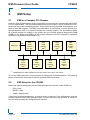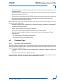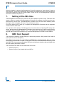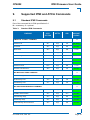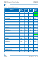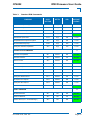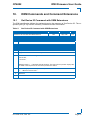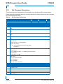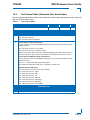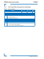
1
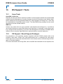
» User Guide «
IPMI Firmware User Guide
for the
CP6002
CPU Board
Doc.ID: 1039-1613, Rev. 2.0
October 26, 2012
If it’s embedded, it’s Kontron.
IPMI Firmware User Guide
CP6002
Revision History
Publication Title: IPMI Firmware User Guide for the CP6002 CPU Module
Doc. ID: 1039-1613
Rev.
Brief Description of Changes
Date of Issue
1.0
Initial issue
21-Oct-2010
2.0
Various minor changes incorporated
26-Oct-2012
Imprint
Kontron Europe GmbH may be contacted via the following:
MAILING ADDRESS
TELEPHONE AND E-MAIL
Kontron Europe GmbH
+49(0)800-SALESKONTRON
Sudetenstraße 7
[email protected]
D-87600 Kaufbeuren Germany
For information about other
Kontron products, please
visit our Internet website:
www.kontron.com
Disclaimer
Copyright ©2010-2012 Kontron AG. All rights reserved. All data is for information purposes only
and not guaranteed for legal purposes. Information has been carefully checked and is believed
to be accurate; however, no responsibility is assumed for inaccuracies. Kontron and the Kontron logo and all other trademarks or registered trade marks are the property of their respective
owners and are recognized. Specifications are subject to change without notice.
Page 2
ID: 1039-1613, Rev. 2.0
CP6002
IPMI Firmware User Guide
Table of Contents
Revision History ........................................................................................................ 2
Imprint ....................................................................................................................... 2
Disclaimer ................................................................................................................. 2
Table of Contents ...................................................................................................... 3
List of Tables ............................................................................................................. 5
1.
Introduction .................................................................................................... 7
1.1 Terminology and Acronym Definitions ......................................................... 7
1.2 Related Publications ................................................................................... 9
1.3 IPMI Overview ............................................................................................. 9
2.
IPMI Setup .................................................................................................... 10
2.1 IPMI in a Compact PCI Chassis ................................................................ 10
2.2 IPMI Setup for the CP6002 ....................................................................... 10
2.3 IPMI Setup for the Rack ............................................................................. 11
3.
Board Management Controller Hardware .................................................. 12
4.
BMC Firmware ............................................................................................. 12
4.1 Key Features ............................................................................................. 12
4.2 Firmware Code .......................................................................................... 13
4.2.1
Structure and Functionality ............................................................... 13
4.2.2
Firmware Upgrade ............................................................................ 14
4.2.3
Firmware / Module Identification ....................................................... 14
4.3 The Payload Boot Process ........................................................................ 14
4.3.1
Boot Flash Selection by Writing to a Board Register ........................ 15
4.3.2
Boot Flash Selection by OEM IPMI Command ................................. 15
4.3.3
Automatic Boot Flash Selection During the Boot Process ................ 15
4.4 OS Boot Order Selection by OEM IPMI .................................................... 15
5.
Communication Between the Management Controller and EFI .............. 16
ID: 1039-1613, Rev. 2.0
Page 3
IPMI Firmware User Guide
6.
CP6002
Hot Swap and Shut Down ........................................................................... 16
6.1 Hot Swap Handle and Hot Swap (Blue) LED ............................................. 16
6.2 The Hot Swap and Shut Down Processes ................................................. 17
7.
Setting of the SEL time ................................................................................ 18
8.
XMC Card Support ....................................................................................... 18
9.
Supported IPMI and ATCA Commands ...................................................... 19
9.1 Standard IPMI Commands ......................................................................... 19
9.2 AdvancedTCA and AMC Commands ........................................................ 25
10. OEM Commands and Command Extensions ............................................ 27
10.1 Get Device ID Command with OEM Extensions ........................................ 27
10.2 Set Firmware Parameters .......................................................................... 28
10.3 Set Control State (Firmware Hub, Boot Order) .......................................... 29
10.4 Get Control State (Firmware Hub, Boot Order) .......................................... 30
11. Sensors Implemented on the CP6002 ........................................................ 31
11.1 Sensor List ................................................................................................. 31
11.2 Sensor Thresholds ..................................................................................... 34
11.3 OEM Event/Reading Types ....................................................................... 35
12. FRU Data ....................................................................................................... 36
12.1 Structure and Functionality ........................................................................ 36
12.2 Board Specific FRU Data ........................................................................... 37
12.3 Downloading the FRU Data ....................................................................... 37
13. OS Support / Tools ....................................................................................... 38
13.1 Linux Tools ................................................................................................. 38
13.2 OS Support - Board Support Packages ..................................................... 38
14. IPMI Module Management LEDs ................................................................. 39
Page 4
ID: 1039-1613, Rev. 2.0
CP6002
IPMI Firmware User Guide
List of Tables
1
Terminology and Acronym Definitions ........................................................... 7
2
Related Publications ..................................................................................... 9
3
Standard IPMI Commands .......................................................................... 19
4
AdvancedTCA and AMC Commands ......................................................... 25
5
Get Device ID Command with OEM Extensions ......................................... 27
6
Set Firmware Parameters ........................................................................... 28
7
Set Control State ......................................................................................... 29
8
Get Control State ........................................................................................ 30
9
Sensor List .................................................................................................. 31
10
Thresholds - Standard and E2 Temperature Range ................................... 34
11
Voltage Sensor Thresholds ......................................................................... 34
12
OEM Event/Reading Types ......................................................................... 35
13
Module Management LEDs Function .......................................................... 40
ID: 1039-1613, Rev. 2.0
Page 5
IPMI Firmware User Guide
CP6002
This page has been intentionally left blank.
Page 6
ID: 1039-1613, Rev. 2.0
CP6002
IPMI Firmware User Guide
1.
Introduction
1.1
Terminology and Acronym Definitions
The following table provides descriptions for terms and acronyms used in this guide. The descriptions are derived primarily from the IPMI specifications.
Table 1:
Terminology and Acronym Definitions
TERM or ACRONYM
BMC
DESCRIPTION
Baseboard Management Controller
In a compact CPCI chassis, there can be only one BMC present. The BMC
administrates the SEL and the SDRR for the complete system. The BMC is connected
to the other boards in the shelf via a dedicated bus (IPMB-0). The CP6002
management controller can be set in SMC mode and in BMC mode by an IPMI OEM
command. The factory setting is SMC.
BSP
Board Support Package
FRU
Field Replaceable Unit
Every board is a FRU. The FRU data contains information about the board such as
the part number and the serial number. See PICMG Specification 2.9 for complete
details on the FRU data structure. The free Linux tool ‘ipmitool’ can be used to update
or to display the FRU data
FWH
Firmware Hub Memory location where a complete EFI BIOS code is stored.
I 2C
Inter-Integrated Circuit
IPMB
Intelligent Platform Management Bus
The dedicated I2C management bus where the BMC and the SMCs communicate.
IPMB-0
Intelligent Platform Management Bus which connects all SMCs with the BMC or a
Shelf Manager.
IPMI
Intelligent Platform Management Interface
KCS
Keyboard Controller Style (Interface)
This is the IPMI mandatory interface on the host system (payload) to communicate
with the BMC.
MP
Management Power.
This powers the BMC or SMC controller.
PICMG
PCI Industrial Computer Manufacturer Group
PWR
Payload Power.
This powers the host side of the board where the application software runs. It is
granted by the BMC or SMC after all prerequisites are met. prerequisites are a closed
handle switch, power on the backplane etc.
ID: 1039-1613, Rev. 2.0
Page 7
IPMI Firmware User Guide
Table 1:
Terminology and Acronym Definitions
TERM or ACRONYM
SDR
CP6002
DESCRIPTION
Sensor Data Record
This is the IPMI data structure that defines a sensor.
SDRR
Sensor Data Record Repository
Is the device in the BMC where all SDRs of the chassis’ boards are administrated. A
free Linux utility named ‘ipmitool’ makes a full chassis discovery and fills the SDRR
with the SDRs being found. The factory default repository contains only the local
board’s SDRs.
SEL
System Event Log
Is the device in the BMC where all the events in the chassis which are reported are
administrated. If an event occurs on any board, the sensor event is sent through the
IPMB bus to the BMC which additionally stores its own events as well.
SMBIOS
System Management BIOS
SMC
Satellite Management Controller
In a compact PCI chassis, there can be many SMCs. Each SMC is connected to the
BMC via a dedicated bus (IPMB-0). The CP6002 management controller can be set in
SMC mode and in BMC mode by an IPMI OEM command. The factory setting is SMC.
SMS
Page 8
System Management Software (designed to run under the OS)
ID: 1039-1613, Rev. 2.0
CP6002
1.2
IPMI Firmware User Guide
Related Publications
The following publications contain information relating to this product.
Table 2:
Related Publications
PRODUCT
PUBLICATION
IPMI
IPMI Specification V2.0 (without LAN support)
IPMI
IPMI- Platform Management FRU Information Storage Definition v1.0,
Document Revision 1.1
IPMI
Addenda, Errata, and Clarifications document revision 4 for IPMI v2.0 rev 1.0
specification
IPMI
Intelligent Platform Management Bus Communications Protocol Specification v1.0
Document Revision 1.0, November 1999
IPMI
IPMB v1.0 Address Allocation Document Revision 1.0, September 1998
PICMG
CompactPCI System Management Specification PICMG 2.9 Rev. 1.0
CP6002
CP6002 User Guide, ID: 1036-6431, Rev. 3.0
CP6002 uEFI BIOS User Guide, ID: 1039-1612, Rev. 2.0
CP6002
CP6002 Linux Board Support Package
IPMI Tools
‘ipmitool’ documentation: http://ipmitool.sourceforge.net
IPMI Tools
OpenIPMI documentation: http://www.openipmi.sourceforge.net
1.3
IPMI Overview
This product fully supports the Intelligent Platform Management Interface (IPMI v2.0, without
LAN support) and PICMG 2.9 R1.0 specifications. All of its IPMI functionality operates under
an autonomous management controller even if the board is held in reset or power down by a
management card within a system designed for High Availability such as XL-VHDS or
XL-LP42.
While the CP6002 IPMI implementation is fully compliant to IPMI v2.0 and should work with any
System Management Software that respects this specification, it has been designed to be easily integrated with the Service Availability Forum-Hardware Platform Interface (SAF-HPI) specification.
More information about Service Availability can be found on the following Web site:
http://www.saforum.org/home
IPMI is an extensible and open standard that defines autonomous system monitoring. It is autonomous because every management controller within a compact PCI chassis monitors its
own sensors and sends critical events through a dedicated bus to a Baseboard Management
Controller (BMC) that logs it into a non-volatile System Event Log (SEL). The CP6002 IPMI implementation includes a device SDR repository module that allows the user's System Management Software (SMS) to detect all system components and to build a database of all
management controller sensors.
For further information concerning IPMI refer to the following Web site:
http://www.intel.com/design/servers/ipmi/
ID: 1039-1613, Rev. 2.0
Page 9
IPMI Firmware User Guide
CP6002
2.
IPMI Setup
2.1
IPMI in a Compact PCI Chassis
Kontron's IPMI implementation in the CompactPCI environment is compliant with the PICMG
2.9 R1.0 specification. This specification defines the pinout of the J1 and J2 CompactPCI connectors as well as the addressing scheme. There should be only one BMC in the chassis, or at
least on the IPMB segment. The BMC may reside either on an CP6002, or on an external system management card, or in a shelf management controller (ShMC). The specification allows
all of these variants. As a BMC in the system slot, the CP6002 supports dual-ported IPMB
(IPMB-0 to the SMCs and IPMB-1 to the external segments via the CompactPCI backplane
connector in accordance with PICMG 2.9).
Backplane
IPMB 1
BMC
SMC
SMC
SMC
IPMB
Address
Fix: 20h
IPMB
Address:
B0h(1)
IPMB
Address:
B2h(1)
IPMB
Address:
B4h(1)
IPMB 0
IPMB 0
(1)
SMC
SMC
SMC
SMC
IPMB
Address:
B6h(1)
IPMB
Address:
B8h (1)
IPMB
Address:
BAh (1)
IPMB
Address:
BCh(1)
IPMB address for SMC is determined via the location of the slot in the chassis
To use the IPMI resources in a rack requires an initial setup for IPMI operation. The following
actions must first be performed to achieve operable IPMI functionality.
2.2
IPMI Setup for the CP6002
Initially the default configuration for the IPMI Management Controller of the CP6002 is:
• IRQ = none
• MODE = SMC
• IPMB = single-ported.
If this is the required configuration, no further action is required. If the configuration must be
modified, either the uEFI shell command “kipmi” or one of the open tools “ipmitool” or “ipmicmd”
may be used to modify the configuration as required.
Page 10
ID: 1039-1613, Rev. 2.0
CP6002
IPMI Firmware User Guide
To use the “kipmi” command, refer to the CP6002 uEFI BIOS User Guide. When EFI stores the
configuration, it creates an ‘IPMI Device Information Record’ entry in the SMBIOS table. This
record contains information about (among others):
• Type of the supported interface (KCS style)
• Selected interrupt (10, 11 or none).
This information is required by the CP6002 payload’s IPMI OS kernel drivers for Linux during
their loading time. After the loading, most available IPMI communications tools which access
the IPMI controller via IPMI OS drivers should work (e.g. ‘ipmicmd’, ‘ipmitool’, etc.).
Now it is possible to use such a tool to issue the “Set Firmware Parameters” OEM IPMI command to modify the configuration again. Changing the interrupt number always requires an EFI
restart for a correct set up of the SMBIOS table.
2.3
IPMI Setup for the Rack
For a working IPMI configuration the SDRR of the BMC must be filled with all sensor data records of all IPMI controllers in the rack. After every system start the BMC uses the SDRR to
initialize all sensors of all boards. The SDRR setup must be done by a management tool e.g.
the open Linux tool ‘ipmitool’. The command then is:
ipmitool sdr fill sensors
This will only work if the IPMI controller of the BMC is addressed. This addressing is the default
if the ‘ipmitool’ is running on the payload side of the board where the BMC is residing.
ID: 1039-1613, Rev. 2.0
Page 11
IPMI Firmware User Guide
3.
CP6002
Board Management Controller Hardware
On the CP6002 CPU board, the BMC is implemented using the NXP ARM7 microcontroller with
512 kB of internal flash and 56 kB of RAM.
An external 64 kB serial EEPROM chip is used for firmware private data and for FRU Inventory
storage. An additional external 4 MB serial SPI-Flash is used for redundant firmware image
storage.
The Board Management Controller implements a local Keyboard Controller Style (KCS)
Interface with interrupt support for communication with system side management software and
the uEFI BIOS. The IPMB bus is used for interconnection with the BMC or Shelf Manager.
The Board Management Controller provides access to various board sensors which permit the
monitoring of:
• System power voltages: 5V (PWR), 3.3V, IPMI 5V, 12V, MMC supply 4.7V
• Temperatures: CPU die, graphic die, PCH, and one board temperature
• Power Good, IPMB-0 link, board reset, post code, boot error, CPU States (processor hot,
thermal trip, …), IPMB-L state, Health error, IPMI watchdog etc.
4.
BMC Firmware
4.1
Key Features
The following are key features of the CP6002 BMC Firmware:
• Compliant with IPMI specification 2.0 (without LAN support)
• Compliant with PICMG 2.9 specification
• Firmware designed and specially made for compact PCI implementation and easy
integration with SAF-HPI
• KCS SMS interface with interrupt support
• Dual-port IPMB support
• Out-of-band management and monitoring using IPMB interface permits access to
sensors regardless of the board's CPU state
• Sensor thresholds fully configurable
• Sensor names prefixed with identification of owner (BMC without slot number or SMC
with slot number)
• Complete IPMI watchdog functionality
• Complete SEL, SDR repository and FRU functionality on BMC
• Complete FRU functionality
• Master Write-Read I2C support for external I2C devices communications (FRU,
EEPROM, FAN)
• Two IPMI controller firmware banks allow an automatic backup. This allows manual and
automatic firmware image roll-back (in case of upgrade failure).
Page 12
ID: 1039-1613, Rev. 2.0
CP6002
IPMI Firmware User Guide
• The downloading of a new firmware image does not break currently running firmware or
payload activities
• Firmware bank management is done by the open tool ‘ipmitool’ function ‘fwum’ which can
update the firmware in the field
• Firmware fully customizable via OEM IPMI commands to satisfy customer requirements
• FRU data can be updated in the field by the open tool ‘ipmitool’ function ‘fru write’
• Interoperable with other IPMI solutions
OEM board supervision and control extensions such as boot device flash selection and firmware boot order configuration.
• Automatic switching to an alternative EFI image after having detected an inoperable EFI
• “Graceful Shut Down” support
• Handle switch and blue Hot Swap LED operation
• The I0 and I1 LEDs indicate operational status of the IPMI Firmware
• The board's write protection feature for non-volatile memories is supported. These
memories are:
• I2C EEPROM for FRU data and parameters
• SPI FLASH memory for firmware banks
4.2
Firmware Code
4.2.1
Structure and Functionality
The IPMI controller firmware code is organized into boot code and operational code, both of
which are stored in a flash module. Upon an IPMI controller reset, the IPMI controller first executes the boot code which does:
• A self test to verify the status of the Management Controller's hardware including its
memory
• Performs a checksum of the operational code
After successful verification of the operational code checksum, the firmware will execute the
operational code. Only the operational code is upgradable in-the-field.
ID: 1039-1613, Rev. 2.0
Page 13
IPMI Firmware User Guide
4.2.2
CP6002
Firmware Upgrade
Firmware upgrading is only possible when write protection is not set.
The standard way to upgrade the IPMI controller's operational code is to use the open tool
‘ipmitool’ together with an image file.
‘ipmitool’ allows the downloading (‘ipmitool fwum download …’) and activation (‘ipmitool fwum
upgrade’) of the new operational code and saves an existing one. The rollback to the formerly
running operational code is possible as well (‘ipmitool fwum rollback’). The status command
(‘ipmitool fwum status’) displays what firmware is stored and in what state it is (‘last known
good’ = running, ‘previous good’ = running before upgrade).
All IPMI interfaces which are offered by ‘ipmitool’ except LAN are usable for the upgrade. This
allows local upgrade and remote upgrade. Please note that the KCS interface is only usable
with a powered payload.
Files which contain an image of operational code have the firmware ID "B340" and the string
"FWUM" in its name.
During the download process the currently running operational code is still operating in a normal way until the upgrade command is issued. During the upgrade start, the IPMI controller is
off line for about 20 seconds while the boot code re-organizes the firmware storage. Afterwards
the new operational code is started. If the new operational code doesn't operate properly (e.g.
hangs up) the boot code will perform an automatic rollback to the last working operational code
and start this again.
4.2.3
Firmware / Module Identification
There are two ways to verify by means of IPMI that a Management Controller resides on a
CP6002.
Invoking the IPMI command “Get Device ID” returns among other information the following
data:
• Manufacturer ID = 3A98h (Kontron IANA ID)
• Product ID = B340 for the firmware
• Firmware Revision in bytes 4:5 - depends on the core version of the running firmware.
• The SDR revision in byte 13 (OEM part of the response) is a sub-revision of the firmware
revision. It is unique for all versions of the board's firmware.
• The Device ID String which can be found by reading the Management Controller Device
Locator Record (SDR Type 12h) contains the string "BMC:x ... x". For example, invoking
the ipmitool command 'ipmitool sdr list mcloc' will return the Device ID Strings of all
available boards. If the CP6002 is a BMC, this string will be displayed without change. If
the CP6002 is an SMC, then the string will be changed into "Sxx: x ... x" where xx is the
slot number where the board is residing, e.g. "S09: x ... x".
4.3
The Payload Boot Process
When the CP6002's payload starts, the first code to be executed is the EFI. There are two Flash
devices, numbered 0 and 1, which may contain different EFI code. Which one of them will be
utilized from the next boot process on is defined by one of two ways:
Page 14
ID: 1039-1613, Rev. 2.0
CP6002
IPMI Firmware User Guide
• The contents of a user (payload) writeable register (refer to the CP6002 User Guide)
defines which Boot Flash to use. This is the primary selection.
• The firmware's parameter EEPROM contains a parameter whose value is used to
determine whether or not to invert the primary selection register's contents when the
Management Controller's firmware selects the Boot Flash. For this the Management
Controller sets or resets a control signal which does or does not invert the Boot Flash
selection.
4.3.1
Boot Flash Selection by Writing to a Board Register
Refer to the CP6002 User Guide for further information concerning Boot Flash selection using
a board register setting.
4.3.2
Boot Flash Selection by OEM IPMI Command
The OEM IPMI command “Set Control State” specifies whether or not the Management
Controller is to invert the register based Flash selection from the next boot process on. The
Management Controller stores this requirement in a parameter in the EEPROM.
4.3.3
Automatic Boot Flash Selection During the Boot Process
After each payload reset the Management Controller selects the Boot Flash by applying the
related EEPROM parameter.
Physically the Management Controller sets or resets a signal line. Afterwards it waits for a
special message from the EFI. This message contains the checksum report, i.e. it indicates the
validity of the Boot Flash's checksum.
If the checksum is wrong or the message is not received within 60 seconds, then the currently
used EFI Flash is assumed to contain an invalid or a corrupted image. In this case, the
Management Controller toggles the parameter value in the EEPROM and issues a “Boot Error
(Invalid boot sector) event” by setting the appropriate sensor value (sensor 'FWHx Boot Err'. x
= 0..1). x is simply the value of the parameter in EEPROM and not the absolute number of the
used Boot Flash. Afterwards it causes a payload off-on cycle and continues as described at the
beginning of this chapter.
When a timeout error is recognized and the count of boot errors exceeds 2, or when a
checksum error is recognized and the count of boot errors exceeds 4 the Management
Controller makes no further attempt to reset/restart the payload. Only at the next power off/on
of the CP6002, will the Management Controller again attempt to start the payload.
4.4
OS Boot Order Selection by OEM IPMI
Normally the EFI will apply the OS boot order which was selected in the EFI menu “Boot/Boot
Option Priorities”. But there is another alternative boot order which is stored in the Management
Controller's non-volatile memory. This boot order can be set and read by IPMI OEM
commands. At payload start the Management Controller writes it into a register where the EFI
can read it. If this Management Controller's boot order has a non-zero value the EFI will use it
instead of its own boot order.
ID: 1039-1613, Rev. 2.0
Page 15
IPMI Firmware User Guide
5.
CP6002
Communication Between the Management
Controller and EFI
For communication between EFI and the Management Controller there is a “private” KCS interface. During the boot process the EFI sends the following IPMI commands to the Management Controller:
• An OEM command which reports a good or a bad checksum.
• A Standard IPMI command “Set Watchdog Timer” to stop a possibly running IPMI
watchdog timer.
• A Standard IPMI command “Set SEL Time” to set the event log time to the time which is
kept by the RTC.
• The OEM IPMI command “Set Firmware Parameters” with some parameters which for
example sets the Management Controller to a BMC or a SMC as selected in the EFI shell.
• A Standard IPMI command “Set ACPI Power State” to set the state “ACPI legacy on”
• Etc.
6.
Hot Swap and Shut Down
6.1
Hot Swap Handle and Hot Swap (Blue) LED
The blue Hot Swap LED (HS LED) of an inserted board in a powered rack is normally used to
indicate the board's operational status so as to facilitate hot-swapping of the board:
• ON
The payload is inactive and may be:
• Activated by closing the Hot Swap Handle, or
• The board may be extracted. The “M-state” is 1.
An exception is the case when payload power is off e.g. after a shut down via an
IPMI chassis command and the handle is still closed. Here the M-state is 4. To
show the operator that the payload power is off, the blue LED will be on in spite of
the closed handle.
• BLINKING
Changing from active state to inactive state or vice versa.
Don't extract the board now. The “M-state” is 2, 5 or 6.
• OFF
The payload is active.
Don't extract the board now. Normally the extraction is impossible because the handle is
closed and locked. The “M-state” is 3 or 4.
Page 16
ID: 1039-1613, Rev. 2.0
CP6002
IPMI Firmware User Guide
Normally the logical states “active” and “inactive” of a payload are identical to the physical
states “handle open” and “handle closed” or “payload power off” and “payload power on”.
If, however, power is switched on or off using IPMI chassis commands or the payload is shut
down by the OS, then the position of the Hot Swap Handle and the power state may become
asynchronous. In this case the blue LED is switched on indicating that the payload power is
switched off although the handle is closed. Such actions are not part of the Hot Swap process
and are governed by their own functionality which is not within the scope of this document.
6.2
The Hot Swap and Shut Down Processes
Hot Swap as defined here, is the purposely initiated process to remove and replace an active
board in a powered system. To accomplish this requires that the hot swap process provide for
an orderly transition of the payload from the active to inactive state and vice versa. This is necessary to preclude improper system operation and possible loss of data. The CP6002 has all
the necessary features including hardware and IPMI software to support hot swapping. On the
software side, however, not all available OS’s support hot swapping, not even partially. Three
possible cases for hot swapping based on OS capabilities are described as follows.
Case 1: Involves an OS which does not support ACPI
After payload power on, the starting EFI will inform the Management Controller by sending the
IPMI command “Set ACPI Power State / Set Legacy on”. This means that a Hot Swap (opening
of the closed handle) shall immediately lead to payload power off by the Management
controller.
In this event, the application/operator is responsible for the termination of all payload processes
prior to initiating removal/replacement of the board to avoid improper operation or loss of data.
Case 2: Involves an OS which emulates ACPI support
An OS which does not really support ACPI, such as VxWorks, is able to obtain “Graceful Shut
Down” support from the Management Controller by performing in the following way.
After start up, such an OS must manipulate the chip set in a way that prevents an immediate
power off when the “power button” is logically activated.
Then it must send the IPMI command “Set ACPI Power State / S0/G0 working” to the Management Controller to enable this to process later on an “S3/G2 soft off” command.
During application operation the system must cyclically read the “Hot Swap Sensor” (sensor
#0) using the IPMI command “Get Sensor Reading”. This allows the tracking of the board's
state. After the board has once reached “M-state” 4 (sensor reading is 10h) the leaving of this
announces that the handle was opened. Now the time has come to terminate all processes.
After all critical processes have been terminated, the OS must send the IPMI command “Set
ACPI Power State / S3/G2 soft off” to the Management Controller which will set the power off
immediately.
Case 3: Involves an OS which supports ACPI
When an OS is started which supports ACPI, the IPMI command “Set ACPI Power State /
S0/G0 working” is sent to the Management Controller. This indicates that the OS has reprogrammed the chip set in such a manner that a “power button” signal does not lead to an immediate power off but only causes an event that can be detected by the OS.
ID: 1039-1613, Rev. 2.0
Page 17
IPMI Firmware User Guide
CP6002
When the handle is opened, the Management Controller asserts the “power button” signal to
notify the OS. The OS then shuts down all processes and afterwards causes the transmission
of the IPMI command “Set ACPI Power State / S3/G2 soft off” to the Management Controller
which then switches the power off.
7.
Setting of the SEL time
The Management Controller does not have its own hardware real time clock. Therefore after
startup, restart or upgrade of the Management Controller, its software clock first must be supplied with the current time. The Management Controller uses the time when handling event
messages which otherwise will have an out-of-date time stamp.
Every time when the EFI starts up, it supplies the Management Controller with the payload's
current real time clock time.
It is a problem with restarts of the Management Controller without a following EFI startup. Because, during restart the Management Controller's time gets lost and it must be set again by
issuing the IPMI command “Set SEL Time”. This may be done by application software on the
payload side via the KCS interface or by a remote Management Controller via the IPMB-0.
8.
XMC Card Support
The presence or absence of XMC card(s) is reported by sensors “XMC present” and “XMC-2
pres” (refer to sensor description).
If an XMC card is present the card's FRU data EEPROM is readable/writable. The size of the
EEPROM must be smaller or equal to 256 bytes, because of 8-bit EEPROM addressing. Note
that XMC FRU size is always reported as 256 bytes and writing to locations that are higher than
the real capacity should be avoided.
The FRU data of the XMC can be read under Linux with:
• ipmitool fru print 1
• ipmitool fru print 2 (on boards with two XMCs)
Page 18
ID: 1039-1613, Rev. 2.0
CP6002
IPMI Firmware User Guide
9.
Supported IPMI and ATCA Commands
9.1
Standard IPMI Commands
Part of the command list in IPMI specification 2.0
M = mandatory, O = optional
Table 3:
Standard IPMI Commands
COMMAND
IPMI 2.0
SPEC.
SECTION
NETFN
CMD
IPM DEVICE “GLOBAL” COMMANDS
KONTRON
SUPPORT
ON BMC
M
Get Device ID
20.1
App
01h
M / Yes [1]
Cold Reset
20.2
App
02h
O / Yes
Warm Reset
20.3
App
03h
O / No
Get Self Test Results
20.4
App
04h
O / Yes
Manufacturing Test On
20.5
App
05h
O / No
Set ACPI Power State
20.6
App
06h
O / Yes
Get ACPI Power State
20.7
App
07h
O / Yes
Get Device GUID
20.8
App
08h
O / No
Broadcast “Get Device ID”
20.9
App
01h
M / Yes
BMC WATCHDOG TIMER COMMANDS
O
Reset Watchdog Timer
27.5
App
22h
O / Yes
Set Watchdog Timer
27.6
App
24h
O / Yes
Get Watchdog Timer
27.7
App
25h
O / Yes
BMC DEVICE AND MESSAGING COMMANDS
O
Set BMC Global Enables
22.1
App
2Eh
O / Yes
Get BMC Global Enables
22.2
App
2Fh
O / Yes
Clear Message Flags
22.3
App
30h
O / Yes
Get Message Flags
22.4
App
31h
O / Yes
Enable Message Channel Receive
22.5
App
32h
O / Yes
ID: 1039-1613, Rev. 2.0
Page 19
IPMI Firmware User Guide
Table 3:
CP6002
Standard IPMI Commands
IPMI 2.0
SPEC.
SECTION
NETFN
CMD
KONTRON
SUPPORT
ON BMC
Get Message
22.6
App
33h
O / Yes
Send Message
22.7
App
34h
O / Yes
Read Event Message Buffer
22.8
App
35h
O / Yes
Get BT Interface Capabilities
22.9
App
36h
O / No
Get System GUID
22.14
App
37h
O / No
Get Channel Authentication Capabilities
22.13
App
38h
O / No
Get Session Challenge
22.15
App
39h
O / No
Activate Session
22.17
App
3Ah
O / No
Set Session Privilege Level
22.18
App
3Bh
O / No
Close Session
22.19
App
3Ch
O / No
Get Session Info
22.20
App
3Dh
O / No
Get AuthCode
22.21
App
3Fh
O / No
Set Channel Access
22.22
App
40h
O / No
Get Channel Access
22.23
App
41h
O / No
Get Channel Info
22.24
App
42h
O / Yes
Set User Access
22.26
App
43h
O / No
Get User Access
22.27
App
44h
O / No
Set User Name
22.28
App
45h
O / No
Get User Name
22.29
App
46h
O / No
Set User Password
22.30
App
47h
O / No
Activate Payload
24.1
App
48h
O / No
Deactivate Payload
24.2
App
49h
O / No
Get Payload Activation Status
24.4
App
4Ah
O / No
Get Payload Instance Info
24.5
App
4Bh
O / No
Set User Payload Access
24.6
App
4Ch
O / No
Get User Payload Access
24.7
App
4Dh
O / No
COMMAND
Page 20
ID: 1039-1613, Rev. 2.0
CP6002
Table 3:
IPMI Firmware User Guide
Standard IPMI Commands
IPMI 2.0
SPEC.
SECTION
NETFN
CMD
KONTRON
SUPPORT
ON BMC
Get Channel Payload Support
24.8
App
4Eh
O / No
Get Channel Payload Version
24.9
App
4Fh
O / No
Get Channel OEM Payload Info
24.10
App
50h
O / No
Master Write-Read
22.11
App
52h
O / Yes
Get Channel Cipher Suits
22.15
App
54h
O / No
Suspend/Resume Payload Encryption
24.3
App
55h
O / No
Set Channel Security Keys
22.25
App
56h
O / No
Get System Interface Capabilities
22.9
App
57h
O / No
COMMAND
CHASSIS DEVICE COMMANDS
O
Get Chassis Capabilities
28.1
Chassis
00h
O / Yes
Get Chassis Status
28.2
Chassis
01h
O / Yes
Chassis Control
28.3
Chassis
02h
O / Yes
Chassis Reset
28.4
Chassis
03h
O / No
Chassis Identify
28.5
Chassis
04h
O / No
Set Chassis Capabilities
28.7
Chassis
05h
O / No
Set Power Restore Policy
28.8
Chassis
06h
O / No
Get System Restart Cause
28.11
Chassis
07h
O / No
Set System Boot Options
28.12
Chassis
08h
O / No
Get System Boot Options
28.13
Chassis
09h
O / No
Get POH Counter
28.14
Chassis
0Fh
O / Yes [2]
EVENT COMMANDS
M
Set Event Receiver
29.1
S/E
00h
M / Yes
Get Event Receiver
29.2
S/E
01h
M / Yes
Platform Event (a.k.a. “Event Message”)
29.3
S/E
02h
M / Yes
ID: 1039-1613, Rev. 2.0
Page 21
IPMI Firmware User Guide
Table 3:
CP6002
Standard IPMI Commands
COMMAND
IPMI 2.0
SPEC.
SECTION
NETFN
CMD
PEF AND ALERTING COMMANDS
KONTRON
SUPPORT
ON BMC
O
Get PEF Capabilities
30.1
S/E
10h
O / No
Arm PEF Postpone Timer
30.2
S/E
11h
O / No
Set PEF Configuration Parameters
30.3
S/E
12h
O / No
Get PEF Configuration Parameters
30.4
S/E
13h
O / No
Set Last Processed Event ID
30.5
S/E
14h
O / No
Get Last Processed Event ID
30.6
S/E
15h
O / No
Alert Immediate
30.7
S/E
16h
O / No
PET Acknowledge
30.8
S/E
17h
O / No
SENSOR DEVICE COMMANDS
M
Get Device SDR Info
35.2
S/E
20h
M / Yes
Get Device SDR
35.3
S/E
21h
M / Yes
Reserve Device SDR Repository
35.4
S/E
22h
M / Yes
Get Sensor Reading Factors
35.5
S/E
23h
O / No
Set Sensor Hysteresis
35.6
S/E
24h
O / Yes
Get Sensor Hysteresis
35.7
S/E
25h
O / Yes
Set Sensor Threshold
35.8
S/E
26h
O / Yes
Get Sensor Threshold
35.9
S/E
27h
O / Yes
Set Sensor Event Enable
35.10
S/E
28h
O / Yes
Get Sensor Event Enable
35.11
S/E
29h
O / Yes
Re-arm Sensor Events
35.12
S/E
2Ah
O / No
Get Sensor Event Status
35.13
S/E
2Bh
O / No
Get Sensor Reading
35.14
S/E
2Dh
M / Yes
Set Sensor Type
35.15
S/E
2Eh
O / No
Get Sensor Type
35.16
S/E
2Fh
O / No
Page 22
ID: 1039-1613, Rev. 2.0
CP6002
Table 3:
IPMI Firmware User Guide
Standard IPMI Commands
COMMAND
IPMI 2.0
SPEC.
SECTION
NETFN
CMD
FRU DEVICE COMMANDS
KONTRON
SUPPORT
ON BMC
M
Get FRU Inventory Area Info
34.1
Storage
10h
M / Yes
Read FRU Data
34.2
Storage
11h
M / Yes
Write FRU Data
34.3
Storage
12h
M / Yes
SDR DEVICE COMMANDS
O
Get SDR Repository Info
33.9
Storage
20h
O / Yes
Get SDR Repository Allocation Info
33.10
Storage
21h
O / Yes
Reserve SDR Repository
33.11
Storage
22h
O / Yes
Get SDR
33.12
Storage
23h
O / Yes
Add SDR
33.13
Storage
24h
O / Yes
Partial Add SDR
33.14
Storage
25h
O / Yes
Delete SDR
33.15
Storage
26h
O / Yes
Clear SDR Repository
33.16
Storage
27h
O / Yes
Get SDR Repository Time
33.17
Storage
28h
O / No
Set SDR Repository Time
33.18
Storage
29h
O / No
Enter SDR Repository Update Mode
33.19
Storage
2Ah
O / No
Exit SDR Repository Update Mode
33.20
Storage
2Bh
O / No
Run Initialization Agent
33.21
Storage
2Ch
O / Yes
SEL DEVICE COMMANDS
O
Get SEL Info
40.2
Storage
40h
O / Yes
Get SEL Allocation Info
40.3
Storage
41h
O / Yes
Reserve SEL
40.4
Storage
42h
O / Yes
Get SEL Entry
40.5
Storage
43h
O / Yes
Add SEL Entry
40.6
Storage
44h
O / Yes
Partial Add SEL Entry
40.7
Storage
45h
O / No
ID: 1039-1613, Rev. 2.0
Page 23
IPMI Firmware User Guide
Table 3:
CP6002
Standard IPMI Commands
IPMI 2.0
SPEC.
SECTION
NETFN
CMD
KONTRON
SUPPORT
ON BMC
Delete SEL Entry
40.8
Storage
46h
O / Yes
Clear SEL
40.9
Storage
47h
O / Yes
Get SEL Time
40.10
Storage
48h
O / Yes
Set SEL Time
40.11
Storage
49h
O / Yes
Get Auxiliary Log Status
40.12
Storage
5Ah
O / No
Set Auxiliary Log Status
40.13
Storage
5Bh
O / No
COMMAND
SERIAL/MODEM DEVICE COMMANDS
O
Set Serial/Modem Configuration
25.1
Transport
10h
O / No
Get Serial/Modem Configuration
25.2
Transport
11h
O / No
Set Serial/Modem Mux
25.3
Transport
12h
O / No
Get TAP Response Codes
25.4
Transport
13h
O / No
Set PPP UDP Proxy Transmit Data
25.5
Transport
14h
O / No
Get PPP UDP Proxy Transmit Data
25.6
Transport
15h
O / No
Send PPP UDP Proxy Packet
25.7
Transport
16h
O / No
Get PPP UDP Proxy Receive Data
25.8
Transport
17h
O / No
Serial/Modem Connection Active
25.9
Transport
18h
O / No
Callback
25.10
Transport
19h
O / No
Set User Callback Options
25.11
Transport
1Ah
O / No
Get User Callback Options
25.12
Transport
1Bh
O / No
SOL Activating
26.1
Transport
20h
O / No
Set SOL Configuration Parameters
26.2
Transport
21h
O / No
Get SOL Configuration Parameters
26.3
Transport
22h
O / No
[1] Has OEM extensions. Please refer to 10.1, Get Device ID Command with OEM Extensions
[2] Response byte 2: hours, byte 3: minutes after module start. Bytes 4..6: void
Page 24
ID: 1039-1613, Rev. 2.0
CP6002
9.2
IPMI Firmware User Guide
AdvancedTCA and AMC Commands
Part of the command list in PICMG 3.0 R 2.0 AdvancedTCA Base Specification and the PICMG
AMC.0 Advanced Mezzanine Card Specification, R 1.0,
M = mandatory, O = optional
Table 4:
AdvancedTCA and AMC Commands
COMMAND
PICMG 3.0
SPEC.
TABLE
NETFN
CMD
AdvancedTCA
KONTRON
SUPPORT
ON MMC
M
Get PICMG Properties
3-9
PICMG
00h
M / Yes
Get Address Info
3-8
PICMG
01h
N/A
Get Shelf Address Info
3-13
PICMG
02h
N/A
Set Shelf Address Info
3-14
PICMG
03h
N/A
FRU Control
3-22
PICMG
04h
N/A
Get FRU LED Properties
3-24
PICMG
05h
M / Yes
Get LED Color Capabilities
3-25
PICMG
06h
M / Yes
Set FRU LED State
3-26
PICMG
07h
M / Yes
Get FRU LED State
3-27
PICMG
08h
M / Yes
Set IPMB State
3-51
PICMG
09h
N/A
Set FRU Activation Policy
3-17
PICMG
0Ah
N/A
Get FRU Activation Policy
3-18
PICMG
0Bh
N/A
Set FRU Activation
3-16
PICMG
0Ch
N/A
Get Device Locator Record ID
3-29
PICMG
0Dh
M / Yes
Set Port State
3-41
PICMG
0Eh
N/A
Get Port State
3-42
PICMG
0Fh
N/A
Compute Power Properties
3-60
PICMG
10h
N/A
Set Power Level
3-62
PICMG
11h
N/A
Get Power Level
3-61
PICMG
12h
N/A
Renegotiate Power
3-66
PICMG
13h
N/A
Get Fan Speed Properties
3-63
PICMG
14h
N/A
ID: 1039-1613, Rev. 2.0
Page 25
IPMI Firmware User Guide
Table 4:
CP6002
AdvancedTCA and AMC Commands
PICMG 3.0
SPEC.
TABLE
NETFN
CMD
KONTRON
SUPPORT
ON MMC
Set Fan Level
3-65
PICMG
15h
N/A
Get Fan Level
3-64
PICMG
16h
N/A
Bused Resource
3-44
PICMG
17h
N/A
Get IPMB Link Info
3-49
PICMG
18h
N/A
COMMAND
Page 26
ID: 1039-1613, Rev. 2.0
CP6002
IPMI Firmware User Guide
10.
OEM Commands and Command Extensions
10.1
Get Device ID Command with OEM Extensions
The IPMI specification defines four optional bytes in the response to 'Get Device ID'. The response bytes [13:16] hold the 'Auxiliary Firmware Revision Information'.
Table 5:
Get Device ID Command with OEM Extensions
COMMAND
LUN
NetFn
CMD
00h
App = 06h
01h
Get Device ID command with OEM extensions
REQUEST DATA
Byte
-
Data Field
-
RESPONSE DATA
Byte
1
2:12
13
Data Field
Completion Code
Regular Get Device ID Command response fields
Release number of the management controller firmware:
10h for R10,
11h for R11,
…
Release number 1… of the IPMI controller firmware. The open ipmi tool ‘ipmitool’ displays this
as ‘SDR’ in the response to the command ‘ipmitool fwum status’.
14
Module Geographical Address (slot number):
1 … = Module in chassis slot 1…
15
Reserved
16
Reserved
ID: 1039-1613, Rev. 2.0
Page 27
IPMI Firmware User Guide
10.2
CP6002
Set Firmware Parameters
This command permits the selection of interrupts to be used during KCS communication.
Please note that parameters which are set while the board is write protected are only valid until
the next IPMI firmware reset.
Table 6:
Set Firmware Parameters
COMMAND
Set Firmware Parameters
LUN
NetFn
CMD
03h
OEM = 3Eh
05h
REQUEST DATA
Byte
Data Field
1
Reserved
B4h
2
Reserved
90h
3
Reserved
91h
4
Reserved
8Bh
5
Cmd Flags
[6:2] Reserved
[1] 0b = get only, 1b = set parameters
[0] 0b = do not reset,
1b = reset Management Controller after setting
parameters
6
Operating Modes
[7:5] Reserved
[4] 0b = IPMB dual-ported, 1b = IPMB single-ported (default)
[3:1] Reserved
[0] 0b = BMC, 1b = SMC
7
IRQ number
FFh = do not use interrupts
0Ah = use IRQ10
0Bh = use IRQ11
Any other values = Reserved
RESPONSE DATA
Byte
Data Field
1
Completion code
2
Cmd flags
3
Operating modes
4
IRQ number
Page 28
ID: 1039-1613, Rev. 2.0
CP6002
10.3
IPMI Firmware User Guide
Set Control State (Firmware Hub, Boot Order)
Please note that parameters which are set while the board is write protected are only valid until
the next IPMI firmware reset.
Table 7:
Set Control State
COMMAND
LUN
NetFn
CMD
Set Control State (Firmware Hub/EFI Flash, Boot Order)
00h
OEM = 3Eh
20h
REQUEST DATA
Byte
Data Field
1
Control ID:
00h: EFI Flash selection
9Dh: EFI Boot Order Configuration
2
Control State for EFI Flash selection:
(These settings are stored in EEPROM and applied (to logic) each time the IPMI controller
detects power-on)
00h = EFI Flash selection is not inverted
01h = EFI Flash selection is logically inverted
Please note that this selection will be automatically toggled by the IPMI controller during a
failing boot process. Other payload sided settings may additionally modify this selection.
Control State for BIOS Boot Order Configuration:
(These settings are stored in EEPROM and applied (to logic) each time the IPMI controller
detects power-on)
00h .. 07h = Selected EFI Boot Order Configuration.
00h selects the default Boot Order which is selected in the EFI menu.
EFI Boot Order Configuration:
00h = Boot order is according to EFI setup (default)
01h = Next boot device is: Floppy
02h = Next boot device is: HDD
03h = Next boot device is: CD
04h = Next boot device is: Network
05h = Next boot device is: USB Floppy
06h = Next boot device is: USB HDD
07h = Next boot device is: USB CDROM
RESPONSE DATA
Byte
1
Data Field
Completion Code
ID: 1039-1613, Rev. 2.0
Page 29
IPMI Firmware User Guide
CP6002
10.4
Get Control State (Firmware Hub, Boot Order)
Table 8:
Get Control State
COMMAND
LUN
NetFn
CMD
Get Control State (Firmware Hub/EFI Flash, Boot Order)
00h
OEM = 3Eh
21h
REQUEST DATA
Byte
Data Field
1
Control ID:
00h = EFI Flash selection
9Dh = EFI Boot Order Configuration
RESPONSE DATA
Byte
Data Field
1
Completion Code
4
Current Control State (see 10.3, Set Control State)
00h .. 01h for control ID = EFI Flash Select
00h .. FFh for control ID = EFI Boot Order Configuration
Page 30
ID: 1039-1613, Rev. 2.0
CP6002
11.
IPMI Firmware User Guide
Sensors Implemented on the CP6002
The sensor name (ID string) has a name prefix which is ‘NNN:’ in the lists below. When reading
the sensor name after module insertion this prefix becomes automatically adapted to the role
(BMC or SMC) and the physical position (slot number) of the module in a rack. If the module's
Management Controller is set up as a BMC the prefix will be ‘BMC:’ independent of the slot
where it resides. If the module's Management Controller is set up as a SMC the prefix will be
‘Sxx:’ where xx is the slot number (e.g. 09).
The sensor number is the number which identifies the sensor e.g. when using the IPMI command ‘Get Sensor Reading’. Please note that ‘ipmitool’ accepts sensor numbers in decimal
(e.g. ‘10’) or hexadecimal (e.g. ‘0xa’) notation.
The IPMI tool ‘ipmitool’ displays for the command ‘ipmitool sdr list’ the contents of the sensor
data record repository (SDRR) of the whole rack if the SDRR has been generated. The generation of the SDRR has always to be redone after adding or removing a board from the rack.
Refer to chapter 2.3, IPMI Setup for the Rack for further information.
11.1
Sensor List
For OEM (Kontron) specific sensor types and codes in the following table please refer to chapter 11.3.
Table 9:
Sensor List
LED I1on
error /
Reading
Mask
SENSOR Number
/
ID string
SENSOR TYPE (CODE) /
EVENT/READING TYPE
(CODE)
Ass. Mask /
Deass. Mask /
Reading Mask
0h /
NNN:Hot Swap
ATCA/CTCA Hot Swap (F0h) /
Sensor-specific (6Fh)
001Fh / 0000h /
001Fh
Hot swap sensor
1h /
NNN:Temp CPU
Temperature (01h) /
Threshold (01h)
1A81h / 7A81h /
3939h
CPU die temperature
Y
/ 0F3Ch
2h /
NNN:Temp PCH
Temperature (01h) /
Threshold (01h)
0A80h / 7A80h /
3838h
Temp Chipset
Y
/ 0F3Ch
3h /
NNN:Temp Graphic
Temperature (01h) /
Threshold (01h)
1A81h / 7A81h /
3939h
Temp Graphic
Y
/ 0F3Ch
4h /
NNN:Temp Board 1
Temperature (01h) /
Threshold (01h)
7A95h / 7A95h /
3F3Fh
Temp Board 1
Y
/ 0F3Ch
5h /
NNN:Pwr Good
Power supply (08h) /
OEM (73h)
0000h / 0000h /
400Fh
Status of all power lines
N
6h /
NNN:Pwr Good Evt
Power supply (08h) /
OEM (73h)
0180h / 7180h /
3838h
Power fail events for all
power lines
Y
/ 402Fh
7h /
NNN:Board 3.3V
Voltage (02h) /
Threshold ( 01h)
2204h / 2204h /
1212h
Board 3.3V supply
Y
/ 0F3Ch
8h /
NNN:Board 5VIPMI
Voltage (02h) /
Threshold ( 01h)
2204h / 2204h /
1212h
Management Power (MP)
5V
Y
/ 0F3Ch
9h /
NNN:Board 5.0V
Voltage (02h) /
Threshold (01h)
2204h / 2204h /
1212h
Board 5V supply
Y
/ 0F3Ch
Ah /
NNN:Board 12V
Voltage (02h) /
Threshold (01h)
2204h / 2204h /
1212h
Board 12V supply
Y
/ 0F3Ch
ID: 1039-1613, Rev. 2.0
DESCRIPTION
N
Page 31
IPMI Firmware User Guide
Table 9:
CP6002
Sensor List
LED I1on
error /
Reading
Mask
SENSOR Number
/
ID string
SENSOR TYPE (CODE) /
EVENT/READING TYPE
(CODE)
Ass. Mask /
Deass. Mask /
Reading Mask
Bh /
NNN:IPMB 5V
Voltage (02h) /
Threshold ( 01h)
2204h / 2204h /
1212h
IPMB 5V supply
N
Ch /
NNN:Fan1 Speed
Fan (04h) /
Threshold (01h)
0000h / 0000h /
1B1Bh
Speed [rpm] Fan 1
N
Dh /
NNN:Fan2 Speed
Fan (04h) /
Threshold (01h)
0000h / 0000h /
1B1Bh
Speed [rpm] Fan 2
N
Eh /
NNN:Last Reset
OEM (CFh) /
‘digital’ Discrete (03h)
0002h / 0000h /
0003h
Board reset event
N
Fh /
NNN:Slot System
Entity presence (25h) /
Sensor-specific (6Fh)
0000h / 0000h /
0003h
Board is in System Slot
(SYSEN)
N
10h /
NNN:PCI Present
Entity presence (25h) /
Sensor-specific (6Fh)
0000h / 0000h /
0003h
Board is selected (BDSEL)
and in system slot (SYSEN)
N
11h /
NNN:CTCA chassis
Entity presence (25h) /
Sensor-specific (6Fh)
0000h / 0000h /
0003h
Value is always 1
N
12h /
NNN:Board PwrOff
Power supply (08h) /
‘digital’ Discrete (03h)
0000h / 0000h /
0003h
13h /
NNN:IPMI WD
Watchdog2 (23h) /
Sensor-specific (6Fh)
010Fh / 0000h /
010Fh
IPMI Watchdog
14h /
NNN:IPMB State
IPMB status change (F1h) /
Sensor-specific (6Fh)
000Fh / 0000h /
000Fh
IPMB-0 state (refer to
PICMG 3.0 Rev 2.0, 3.8.4.1)
N
15h /
NNN:ACPI State
System ACPI Power State
(022h) / Sensor-specific (6Fh)
7FFFh / 0000h /
7FFFh
System ACPI Power State
N
16h /
NNN:Health Error
Platform Alert (24h) /
‘digital’ Discrete (03h)
0000h / 0000h /
0003h
Aggregates states (power,
temperatures etc.).
Visualization by the Health
LED.
N
17h /
NNN:CPU 0 Status
Processor (07h) /
Sensor-specific (6Fh)
0463h / 0400h /
04E3h
CPU status.
Offset 0ah: “Processor
Automatically Throttled”
18h /
NNN:POST Value
POST value OEM (C6h) /
Sensor-specific (6Fh)
4000h / 0000h /
40FFh
POST code value (port 80h)
N
19h /
NNN:FWH0 BootErr
Boot error (1Eh) /
Sensor-specific (6Fh)
0008h / 0008h /
0008h
Firmware Hub 0 (Boot Flash
0) boot error
Y
/ 0008h
1Ah /
NNN:FWH1 BootErr
Boot error (1Eh) /
Sensor-specific (6Fh)
0008h / 0008h /
0008h
Firmware Hub 1 (Boot Flash
1) boot error
Y
/ 0008h
1Bh /
NNN:XMC present
Entity Presence (25h) /
Sensor-specific (6Fh)
0000h / 0000h /
0003h
Presence of XMC-A board
N
1Ch /
NNN:XMC-2 pres
Entity Presence (25h) /
Sensor-specific (6Fh)
0000h / 0000h /
0003h
Presence of XMC-B board
N
1Dh /
NNN:Pwr Denied
Platform Alert (24h) /
‘digital’ Discrete (03h)
0002h / 0002h /
0003h
1 = o.k., no alert, power not
denied
N
1Eh /
NNN:FRU Agent
OEM FRU Agent (C5h) /
Discrete (0Ah)
0140h / 0000h /
0147h
FRU Initialization Agent
state
Page 32
DESCRIPTION
N
Y
/ 010Fh
Y
/ 0402h
Y
/ 0140h
ID: 1039-1613, Rev. 2.0
CP6002
Table 9:
IPMI Firmware User Guide
Sensor List
LED I1on
error /
Reading
Mask
SENSOR Number
/
ID string
SENSOR TYPE (CODE) /
EVENT/READING TYPE
(CODE)
Ass. Mask /
Deass. Mask /
Reading Mask
1Fh /
NNN:IPMC Storage
Management Subsystem
Health (28h) /
Sensor-specific (6Fh)
0002h / 0000h /
0003h
IPMI controller storage
access error
20h /
NNN:IpmC Reboot
Platform Alert (24h) /
‘digital’ Discrete (03h)
0002h / 0000h /
0003h
2 = Management controller
is (re-)booting
N
21h /
NNN:SEL State
Event Logging Disabled (10h) 003Ch / 0000h /
/
003Ch
Sensor-specific (6Fh)
State of event logging
N
22h /
NNN:IPMI Info-1
OEM Firmware Info 1 (C0h) /
OEM (70h)
0003h / 0000h /
7FFFh
For internal use only
N
23h /
NNN:IPMI Info-2
OEM Firmware Info 2 (C0h) /
OEM (71h)
0003h / 0000h /
7FFFh
For internal use only
N
24h /
NNN:IniAgent Err
Initialization Agent (C2h) /
‘digital’ Discrete (03h)
0002h / 0000h /
0003h
Initialization Agent error
status. Used on BMC only.
1 = error free
N
25h /
NNN:Board Rev
OEM Board Revision (CEh)/
Sensor-specific (6Fh)
0000h / 0000h /
7FFFh
Board revision information
N
ID: 1039-1613, Rev. 2.0
DESCRIPTION
Y
/ 0002h
Page 33
IPMI Firmware User Guide
11.2
CP6002
Sensor Thresholds
The CP6002 CPU module is available for two different operating temperature ranges. For each
operating temperature range, standard and extended (E2), a set of temperature thresholds for
the sensors is defined. The thresholds defined in Table 10 are the same for both temperature
ranges except for sensor 04h. The far right column indicates the thresholds for the E2 range
for the sensor 04h.
Table 11 provides voltage sensor thresholds.
Table 10: Thresholds - Standard and E2 Temperature Range
04h /
NNN:Temp
Board
(E2 RANGE)
04h /
NNN:Temp
Board
Sensor Number /
ID string
01h /
NNN:Temp
CPU
02h /
NNN:Temp
PCH
03h /
NNN:Temp
Graphic
Upper non-recoverable
115 °C
116 °C
110 °C
95 °C
95 °C
Upper critical
105 °C
111 °C
100 °C
90 °C
90 °C
Upper non critical
95 °C
101 °C
90 °C
85 °C
85 °C
Normal max
90 °C
96 °C
85 °C
75 °C
75 °C
Nominal
80 °C
86 °C
75 °C
65 °C
65 °C
Normal min
3 °C
3 °C
3 °C
0 °C
- 40 °C
Lower non-critical
1 °C
n.a.
1 °C
- 1 °C
- 41 °C
Lower critical
n.a.
n.a.
n.a.
- 3 °C
- 43 °C
Lower non-recoverable
n.a.
n.a.
n.a.
- 5 °C
- 45 °C
Table 11: Voltage Sensor Thresholds
Sensor Number /
ID string
Upper non-recoverable
07h /
NNN:Board
3.3V
08h /
NNN:Board
5VIPMI
09h /
NNN:Board
5.0V
0Ah /
NNN:Board
12V
0Bh /
NNN:IPMB
5V
n.a.
n.a.
n.a.
n.a.
n.a.
3.503 V
5.004 V
5.310 V
12.715 V
5.310 V
n.a.
n.a.
n.a.
n.a.
n.a.
Normal max
3.460 V
4.938 V
5.245 V
12.598 V
5.245 V
Nominal
3.302 V
4.697 V
5.007 V
12.012 V
5.007 V
Normal min
3.202 V
4.455 V
4.769 V
11.426 V
4.769 V
n.a.
n.a.
n.a.
n.a.
n.a.
3.173 V
4.389 V
4.704 V
11.309 V
4.704 V
n.a.
n.a.
n.a.
n.a.
n.a.
Upper critical
Upper non critical
Lower non-critical
Lower critical
Lower non-recoverable
Page 34
ID: 1039-1613, Rev. 2.0
CP6002
11.3
IPMI Firmware User Guide
OEM Event/Reading Types
OEM (Kontron) specific sensor types and codes are presented in the following table.
Table 12: OEM Event/Reading Types
OEM
SENSOR
TYPE (CODE)
OEM
EVENT/READING
TYPE (CODE)
DESCRIPTION
Firmware Info 1 (C0h)
70h
Internal Diagnostic Data
Firmware Info 2 (C0h)
71h
Internal Diagnostic Data
Initialization Agent (C2h)
03h
('digital' Discrete)
Offsets / events:
FRU Agent (C5h)
0Ah
(Discrete)
FRU initialization agent, using a standard reading type.
Post Value (C6h)
6Fh
(sensor type specific)
Error is detected if the POST code is != 0 and doesn't
change for a defined amount of time.
0: Initialization O.K.
1: Initialization Error
In case of no error:
Bits [7:0] = POST code (payload Port 80h)
In case of error:
Bits [15:0] = 4000h
Data2 = POST code, low nibble
Data3 = POST code, high nibble
Firmware Upgrade Manager
(C7h)
6Fh
(sensor type specific)
Offsets / events:
Board Reset (CFh)
03h
('digital' Discrete)
Data 2 contains the reset type:
0 : First Boot after upgrade
1 : First Boot after rollback (error)
2 : First Boot after errors (watchdog)
3 : First Boot after manual rollback
4..7 : Reserved
8 : Firmware Watchdog Bite, reset occurred
…WARM = 0
…COLD = 1
…FORCED_COLD = 2
…SOFT_RESET = 3
…MAX = 4
Data 3 contains the reset source:
…IPMI_WATCHDOG = 0
…IPMI_COMMAND = 1
…PROC_INT_CHECKSTOP = 2
…PROC_INT_RST = 3
…RESET_BUTTON = 4
…POWER_UP = 5
…LEG_INITIAL_WATCHDOG = 6
…LEG_PROG_WATCHDOG = 7
…SOFTWARE_INITIATED = 8
…SETUP_RESET = 9
…UNKNOWN = 0xFF
ID: 1039-1613, Rev. 2.0
Page 35
IPMI Firmware User Guide
CP6002
Table 12: OEM Event/Reading Types
OEM
SENSOR
TYPE (CODE)
OEM
EVENT/READING
TYPE (CODE)
73h
DESCRIPTION
Sensor-specific
Offset
Event
Power Good /
Power Good Event
0h
HS fault#
1h
HS early fault#
2h
DEG#
3h
FAL#
4h
n.a.
5h
n.a.
6h
n.a.
7h
n.a.
8h
n.a.
9h
n.a.
Ah
n.a.
Bh
n.a.
Ch
n.a.
Dh
n.a.
Eh
vccMainGood
e.g. for
Board revision (CEh)
6Fh
Bits [7:0] = Board Revision number
(sensor type specific)
This corresponds to Board and PLD Revision register
described in CP6002 board manual.
12.
FRU Data
12.1
Structure and Functionality
The Management Controller provides 4 kB non-volatile storage space for FRU information.
Please refer to Related Publications: IPMI- Platform Management FRU Information Storage
Definition v1.0, Document Revision 1.1 which defines the structure of FRU data.
Full low-level access to read or write a module's FRU Information is provided by regular IPMI
FRU Device commands. Care must be taken when writing FRU information directly using standard IPMI commands because there is no write protection. Invalid FRU information may disturb
a shelf management software which uses the FRU data.
To avoid this situation there is a Kontron Linux tool 'frum', which permits displaying and partial
modification of FRU data. For example, the 'frum' tool makes it easy to modify Product Info
Area fields like Product Version or Product Serial Number.
Page 36
ID: 1039-1613, Rev. 2.0
CP6002
12.2
IPMI Firmware User Guide
Board Specific FRU Data
Supported are the following FRU data areas and data fields:
FRU Board Info Area
• Manufacturing date / time
• Board manufacturer
(C7): “Kontron”
• Board Product Name
(C6): “CP6002”
• Board Serial Number
(CF): “123456789012345” 1)
• Board Part Number
(C9): “123456789” 1)
• FRU File ID
(C7): “STD_R10”
FRU Product Info Area
1)
2)
• Product manufacturer
(C7): “Kontron”
• Product Name
(C6): “CP6002”
• Product Part Number
(C2): “00” 1)
• Product Version
(D9): “0000000000000000000000000” 2)
• Product Serial Number
(D9): “0000000000000000000000000” 2)
• Asset Tag
(D9): “_________________________” 2)
• FRU File ID
(C7): “STD_R10”
• CustomData
(D5): “MAC=CC:CC:CC:CC:CC:CC” 1)
Field will be modified during the manufacturing process
Field is free for user. Please note that changes need special care (checksums).
12.3
Downloading the FRU Data
Normally a download of the FRU data is not required because the module is supplied with it
before shipping.
But if needed the standard way to download FRU information to the module is to use the open
tool ‘ipmitool’ for the download of an image file (e.g. ‘ipmitool fru write 0 <file name>’).
All IPMI interfaces which are offered by ‘ipmitool’ are usable. This allows local upgrade or remote upgrade. Please note that the KCS interface is only usable on a powered payload.
Please note that the writing of FRU data while the board is write protected will have no effect.
ID: 1039-1613, Rev. 2.0
Page 37
IPMI Firmware User Guide
13.
OS Support / Tools
13.1
Linux Tools
CP6002
OpenIPMI - KCS driver
Normally all drivers and kernel modules needed for communication between the payload sided
software and the Management Controller firmware via the KCS interface come with the distribution. Newest sources can be downloaded from: ‘http://openipmi.sourceforge.net’. There may
be downloaded the OpenIPMI project as well. The OpenIPMI library package includes some
applications and the needed libraries.
IPMI Tool
Another very useful all-in-one tool is ‘ipmitool’ (http://ipmitool.sourceforge.net ). It provides a
user friendly interface to many IPMI features and extensions, for example, to get sensor readings, change sensor thresholds or to access other Management Controllers via IPMB. Before
‘ipmitool’ can be used the OpenIPMI driver, mentioned above, must be loaded too.
13.2
OS Support - Board Support Packages
For information on the operating systems supported with the CP6002, please refer to the
CP6002’s data sheet. Please visit “http://www.kontron.com” to download the data sheet.
Please also have a look at the download section for the latest versions of Board Support Packages or Firmware Updates.
For further information concerning IPMI, refer to the BSP documentation for the respective OS.
Page 38
ID: 1039-1613, Rev. 2.0
CP6002
14.
IPMI Firmware User Guide
IPMI Module Management LEDs
There are three IPMI Module Management LEDs on the front panel of the CP6002. The following figure illustrates the location of the LEDs.
IPMI LEDS
I0 and I1
HOT SWAP
LED
CP6002-R1
CP6002-R1-MC CP6002-R2-MC
ID: 1039-1613, Rev. 2.0
Page 39
IPMI Firmware User Guide
CP6002
The following table describes the functioning of the Module Management LEDs.
Table 13: Module Management LEDs Function
OVERRIDE MODE
LED
LED I0
LED I1
HS LED
(Hot Swap
LED)
COLOR
green
green
blue
STATE
NORMAL MODE
selectable by user or
SMS/SMM
off
IPMI Controller operating
By user:
slow blinking
IPMI Controller request attention of the
SMS/SMM
fast blinking
Send/receive data through the IPMB bus
on steady
IPMI Controller not operating
off
IPMI Controller not operating
slow blinking
IPMI Controller heart beat
fast blinking
Send/receive data through the KCS interface
on steady
Health error detected
off
Module is in normal operation
(do not extract the module)
blinking
Module hot swap in progress;
module not ready for extraction
on
a) Module ready for hot swap extraction, or
• Only lamp test
By user:
• Only lamp test
By SMS/SMM:
• On
• Off
• Slow/Fast Blinking
b) Module has just been inserted in a powered
system
Page 40
By user:
• Only lamp test
ID: 1039-1613, Rev. 2.0